

Page 1
ORDER No.AED02100465
AUTOMOTIVE ELECTRONICS
GM
CY-BG8013ZC
6-channels Power Amplifier
GM PART No. : 15762536
VEHICLE : Yukon, Tahoe, Suburban
DESTINATION : US /Mexico
PRODUCED AFTER: Jul., 1999
I0
Specifications*
General
Power Supply DC 12V (11V - 16V)
Test Voltage 13.2V
Negative ground
Current Consumption Less than 2A
Maximum Output Power 20W × 5ch (FL, FR, RL, RR, AMB) (at 4Ω)
26W × 1ch (SUB) (at 4Ω)
Output Impedance 4Ω (FL, FR, RL, RR, AMB)
2Ω (SUB)
Source Impedance 600Ω or less
Input Level 0dBV (1Vrms)
THD 0.5% max. (FL, FR, RL, RR, AMB)
1.5% max. (SUB)
Output Noise -67dBV max. (each channel)
Channel Separation 55dB min. (at 500Hz)
Dimensions** (W×H×D) 167.4 × 140 × 39.1 (mm)
(not including connector protrusion)
Weight** 1.0kg
* Specifications and the design are subject to possible modification
without notice due to improvements.
** Dimensions and Weight shown are approximate.
•
• Above specifications comply with EIA standards.
• •
© 2002 Matsushita Communication Industrial Co.,
Ltd. All rights reserved. Unauthorized copying and
distribution is a violation of law.
Page 2
GM / CY-BG8013ZC
CONTENTS
Page Page
1 FEATURES 2
2 REAR VIEW AND CONNECTORS
3 BLOCK DIAGRAM
4 PACKAGE AND IC BLOCK DIAGRAM
5 REPLACEMENT PARTS LIST
2
6 EXPLODED VIEW (UNIT)
3
7 WIRING DIAGRAM
8 SCHEMATIC DIAGRAM
4
1 FEATURES
•
•
6 channels of amplification: LF, RF, LR, RR, AMB (Ambience) and SUB (Subwoofer).
• •
•
•
3 bands of fixed equalization for each front channel.
• •
2 bands of fixed equalization for each rear channel.
LPF for Subwoofer.
•
•
The amplifier shall untilize AMP CONTROL to invoke amplifier function as follows:
• •
For AMP CONTROL signal from 0 Vdc to 1.0 Vdc, amplifier shall be off.
For AMP CONTROL signal from 2.5 Vdc to voltage BATT12V terminal, amplifier shall be on.
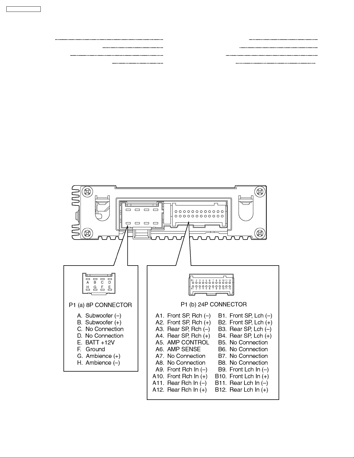
2 REAR VIEW AND CONNECTORS
5
8
9
11
2
Page 3
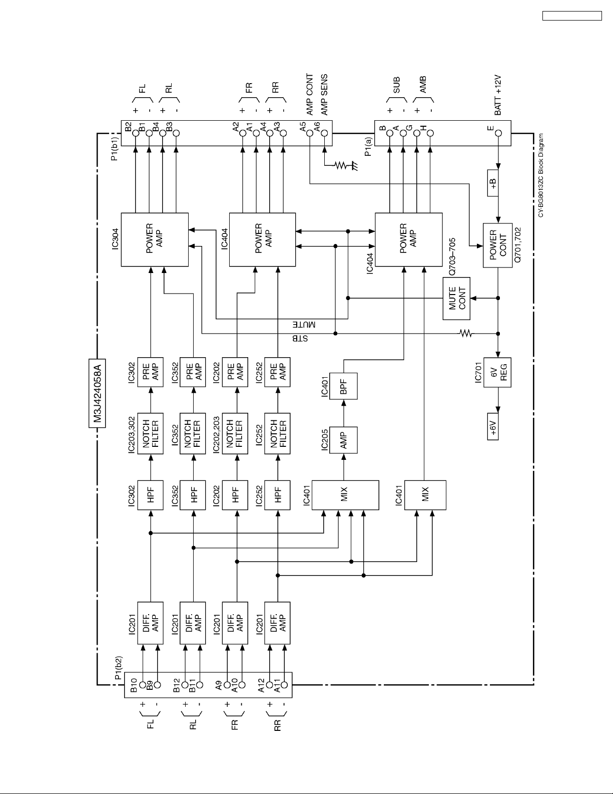
3 BLOCK DIAGRAM
3.1. Main Block
GM / CY-BG8013ZC
3
Page 4
GM / CY-BG8013ZC
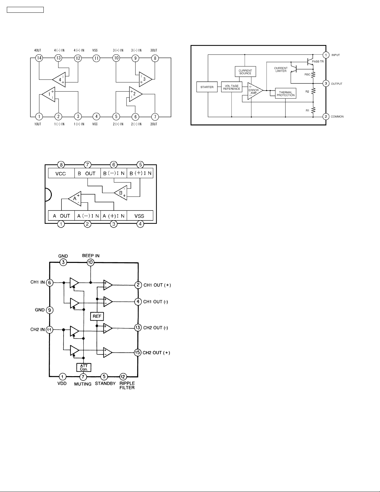
4 PACKAGE AND IC BLOCK DIAGRAM
4.1. MAIN BLOCK
IC201, 202, 252 : YEAMPC4574E1
IC302, 352, 401 : YEAMPC4574E1
IC203, 205 : YEAMPC4570E1
IC701 : MC7806BT
IC204, 304, 404 : AN7190NK
4
Page 5

5 REPLACEMENT PARTS
LIST
Notes :
1. Be sure to make your orders of replacement parts
according to this list.
2. Important safety notice: Components, identified by
have special characteristics important for safety. When
replacing any of these components, use only
manufacturer´s specified parts.
3. Location keys in the remarks column indicates the general
location of the parts shown in the exploded drawing, as in a
road map.
4. The marking (RTL) indicates that Retention Time is limited
for this item. After the discontinuation of assembly in
production, the item will continue to be available for a
specific period of time. The retention period of availability is
dependent on the type of assembly, and in accordance with
the laws governing part and product retention. After the end
of this period, the assembly will no longer be available.
5. "MCC" marks in remarkscolumn are indicated supply parts
of Matsushita Communication Industrial Corp. of America
(MCC).
Ref.
No.
[M3J424058A]
IC´s and TRANSISTORs
IC201 YEAMPC4574E1 IC MCC
IC202 YEAMPC4574E1 IC MCC
IC203 YEAMPC4570E1 IC MCC
IC204 AN7190NK IC
IC205 YEAMPC4570E1 IC MCC
IC252 YEAMPC4574E1 IC MCC
IC302 YEAMPC4574E1 IC MCC
IC304 AN7190NK IC
IC352 YEAMPC4574E1 IC MCC
IC401 YEAMPC4574E1 IC MCC
IC404 AN7190NK IC
IC701 MC7806BT IC MCC
Q701 2SB1073TX Transistor
Q702 YEANC3661TA Transistor
Q703 B1ABCF000042 Transistor
Q704 YEANC3661TA Transistor
Q705 YEANC3661TA Transistor
DIODEs
D201 MA3X15300L Diode MCC
D202 MA3X15300L Diode MCC
D251 MA3X15300L Diode MCC
D252 MA3X15300L Diode MCC
D301 MA3X15300L Diode MCC
D302 MA3X15300L Diode MCC
D351 MA3X15300L Diode MCC
D352 MA3X15300L Diode MCC
D701 YEAD30D2FC6 Diode
D702 MA3X15300L Diode MCC
D703 YEAD30D2FC6 Diode
D704 MA3X15300L Diode MCC
D705 MA3X15300L Diode MCC
CAPACITORs
C200 YECUS1H221JM Ceramic, 220PF 50WV
C201 ECEA1CSN100I Electrolytic, 10µF 16WV
C202 ECEA1CSN100I Electrolytic, 10µF 16WV
C203 YECUS1H221JM Ceramic, 220PF 50WV
C204 YECUS1H221JM Ceramic, 220PF 50WV
Part No. Part Name & Description Remarks
mark
Ref.
No.
C205 YECUS1E473KX Ceramic, 0.047µF 25WV
C206 YECUS1E473KX Ceramic, 0.047µF 25WV
C207 F1J1C274A006 Ceramic, 0.27µF 16WV
C208 YECUS1H273KX Ceramic, 0.027µF 50WV
C209 YECUS1H183KX Ceramic, 0.018µF 50WV
C210 YECUS1H273KX Ceramic, 0.027µF 50WV
C211 F1J1H223A035 Ceramic, 0.022µF 50WV
C212 YECUS1H122KX Ceramic, 1200PF 50WV
C221 ECEA1CKA100I Electrolytic, 10µF 16WV
C222 YECUS1H152KX Ceramic, 1500PF 50WV
C223 YECUS1C224KX Ceramic, 0.22µF 16WV
C224 YECUS1C224KX Ceramic, 0.22µF 16WV
C225 YECUS1H471JM Ceramic, 470PF 50WV
C226 YECUS1H471JM Ceramic, 470PF 50WV
C227 YECUS1H471JM Ceramic, 470PF 50WV
C228 YECUS1H471JM Ceramic, 470PF 50WV
C231 YECUS1H103KX Ceramic, 0.01µF 50WV
C232 ECEA1CKA100I Electrolytic, 10µF 16WV
C233 ECA1CM222B Electrolytic, 2200µF 16WV
C241 YECUS1H104KX Ceramic, 0.1µF 50WV
C242 YECUS1H104KX Ceramic, 0.1µF 50WV
C243 YECUS1H104KX Ceramic, 0.1µF 50WV
C244 YECUS1H104KX Ceramic, 0.1µF 50WV
C245 YECUS1H104KX Ceramic, 0.1µF 50WV
C246 YECUS1C224KX Ceramic, 0.22µF 16WV
C247 YECUS1H102KX Ceramic, 1000PF 50WV
C248 YECUS1C224KX Ceramic, 0.22µF 16WV
C249 YECUS1H102KX Ceramic, 1000PF 50WV
C250 YECUS1H221JM Ceramic, 220PF 50WV
C251 ECEA1CSN100I Electrolytic, 10µF 16WV
C252 ECEA1CSN100I Electrolytic, 10µF 16WV
C253 YECUS1H221JM Ceramic, 220PF 50WV
C254 YECUS1H221JM Ceramic, 220PF 50WV
C255 YECUS1E473KX Ceramic, 0.047µF 25WV
C256 YECUS1E473KX Ceramic, 0.047µF 25WV
C257 F1J1C394A006 Ceramic, 0.39µF 16WV
C258 F1J1H223A035 Ceramic, 0.022µF 50WV
C259 YECUS1C563KX Ceramic, 0.056µF 16WV
C260 F1J1H182A509 Ceramic, 1800PF 50WV
C271 ECEA1CKA100I Electrolytic, 10µF 16WV
C272 YECUS1H152KX Ceramic, 1500PF 50WV
C273 YECUS1C224KX Ceramic, 0.22µF 16WV
C274 YECUS1C224KX Ceramic, 0.22µF 16WV
C275 YECUS1H471JM Ceramic, 470PF 50WV
C276 YECUS1H471JM Ceramic, 470PF 50WV
C277 YECUS1H471JM Ceramic, 470PF 50WV
C278 YECUS1H471JM Ceramic, 470PF 50WV
C300 YECUS1H221JM Ceramic, 220PF 50WV
C301 ECEA1CSN100I Electrolytic, 10µF 16WV
C302 ECEA1CSN100I Electrolytic, 10µF 16WV
C303 YECUS1H221JM Ceramic, 220PF 50WV
C304 YECUS1H221JM Ceramic, 220PF 50WV
C305 YECUS1E473KX Ceramic, 0.047µF 25WV
C306 YECUS1E473KX Ceramic, 0.047µF 25WV
C307 YECUS1C563KX Ceramic, 0.056µF 16WV
C308 YECUS1C154KX Ceramic, 0.15µF 16WV
C309 YECUS1E393KX Ceramic, 0.039µF 25WV
C310 YECUS1C683KX Ceramic, 0.068µF 16WV
C311 F1J1H223A035 Ceramic, 0.022µF 50WV
C312 YECUS1H122KX Ceramic, 1200PF 50WV
C321 ECEA1CKA100I Electrolytic, 10µF 16WV
C322 YECUS1H152KX Ceramic, 1500PF 50WV
C323 YECUS1C224KX Ceramic, 0.22µF 16WV
C324 YECUS1C224KX Ceramic, 0.22µF 16WV
C325 YECUS1H471JM Ceramic, 470PF 50WV
C326 YECUS1H471JM Ceramic, 470PF 50WV
C327 YECUS1H471JM Ceramic, 470PF 50WV
C328 YECUS1H471JM Ceramic, 470PF 50WV
C331 YECUS1H103KX Ceramic, 0.01µF 50WV
C332 ECEA1CKA100I Electrolytic, 10µF 16WV
C333 ECA1CM222B Electrolytic, 2200µF 16WV
C341 YECUS1H104KX Ceramic, 0.1µF 50WV
C342 YECUS1H104KX Ceramic, 0.1µF 50WV
Part No. Part Name & Description Remarks
GM / CY-BG8013ZC
5
Page 6

GM / CY-BG8013ZC
Ref.
No.
C350 YECUS1H221JM Ceramic, 220PF 50WV
C351 ECEA1CSN100I Electrolytic, 10µF 16WV
C352 ECEA1CSN100I Electrolytic, 10µF 16WV
C353 YECUS1H221JM Ceramic, 220PF 50WV
C354 YECUS1H221JM Ceramic, 220PF 50WV
C355 YECUS1E473KX Ceramic, 0.047µF 25WV
C356 YECUS1E473KX Ceramic, 0.047µF 25WV
C357 F1J1C394A006 Ceramic, 0.39µF 16WV
C358 F1J1H223A035 Ceramic, 0.022µF 50WV
C359 YECUS1C563KX Ceramic, 0.056µF 16WV
C360 F1J1H182A509 Ceramic, 1800PF 50WV
C371 ECEA1CKA100I Electrolytic, 10µF 16WV
C372 YECUS1H152KX Ceramic, 1500PF 50WV
C373 YECUS1C224KX Ceramic, 0.22µF 16WV
C374 YECUS1C224KX Ceramic, 0.22µF 16WV
C375 YECUS1H471JM Ceramic, 470PF 50WV
C376 YECUS1H471JM Ceramic, 470PF 50WV
C377 YECUS1H471JM Ceramic, 470PF 50WV
C378 YECUS1H471JM Ceramic, 470PF 50WV
C401 YECUS1C224KX Ceramic, 0.22µF 16WV
C402 YECUS1C224KX Ceramic, 0.22µF 16WV
C403 YECUS1C224KX Ceramic, 0.22µF 16WV
C404 YECUS1H273KX Ceramic, 0.027µF 50WV
C405 YECUS1C224KX Ceramic, 0.22µF 16WV
C406 YECUS1C224KX Ceramic, 0.22µF 16WV
C421 ECEA1CKA100I Electrolytic, 10µF 16WV
C422 YECUS1H152KX Ceramic, 1500PF 50WV
C423 YECUS1C224KX Ceramic, 0.22µF 16WV
C424 YECUS1C224KX Ceramic, 0.22µF 16WV
C427 YECUS1H471JM Ceramic, 470PF 50WV
C428 YECUS1H471JM Ceramic, 470PF 50WV
C431 YECUS1H103KX Ceramic, 0.01µF 50WV
C432 ECEA1CKA100I Electrolytic, 10µF 16WV
C433 ECA1CM222B Electrolytic, 2200µF 16WV
C441 YECUS1H104KX Ceramic, 0.1µF 50WV
C450 YECUS1H472KX Ceramic, 4700PF 50WV
C451 YECUS1H822KX Ceramic, 8200PF 50WV
C452 YECUS1H822KX Ceramic, 8200PF 50WV
C471 ECEA1CKA100I Electrolytic, 10µF 16WV
C472 YECUS1H152KX Ceramic, 1500PF 50WV
C473 YECUS1C224KX Ceramic, 0.22µF 16WV
C474 YECUS1C224KX Ceramic, 0.22µF 16WV
C475 ECA1CM331 Electrolytic, 330µF 16WV
C477 YECUS1H471JM Ceramic, 470PF 50WV
C478 YECUS1H471JM Ceramic, 470PF 50WV
C701 YECUS1H104KX Ceramic, 0.1µF 50WV
C702 ECA1CM222B Electrolytic, 2200µF 16WV
C703 YECUS1H104KX Ceramic, 0.1µF 50WV
C704 YECUS1H104KX Ceramic, 0.1µF 50WV
C705 YECUS1H104KX Ceramic, 0.1µF 50WV
C706 ECA1CM222B Electrolytic, 2200µF 16WV
C707 YECUS1H104KX Ceramic, 0.1µF 50WV
C708 ECEA1HKS2R2I Electrolytic, 2.2µF 50WV
C709 ECA1CM331 Electrolytic, 330µF 16WV
C710 ECA1CM331 Electrolytic, 330µF 16WV
C712 YECUS1H471JM Ceramic, 470PF 50WV
C721 YECUS1H471JM Ceramic, 470PF 50WV
RESISTORs
R201 ERJ6ENF4752V Chip, 47.5k
R202 ERJ6ENF4752V Chip, 47.5k
R203 ERJ6ENF4751V Chip, 4.75k
R204 ERJ6ENF4751V Chip, 4.75k
R205 ERJ6GEYJ273 Chip, 27k
R206 ERJ6GEYJ563 Chip, 56k
R207 ERJ6GEYJ152 Chip, 1.5k
R208 ERJ6GEYJ154 Chip, 150k
R209 ERJ6GEYJ562 Chip, 5.6k
R210 ERJ6GEYJ154 Chip, 150k
R211 ERJ6GEYJ822 Chip, 8.2k
R212 ERJ6GEYJ184 Chip, 180k
R213 ERJ6GEY0R00 Chip, 0
Part No. Part Name & Description Remarks
ΩΩΩΩ
ΩΩΩΩ
ΩΩΩΩ
ΩΩΩΩ
ΩΩΩΩ
ΩΩΩΩ
ΩΩΩΩ
ΩΩΩΩ
ΩΩΩΩ
1/10W
ΩΩΩΩ
1/10W
ΩΩΩΩ
1/10W
ΩΩΩΩ
1/10W MCC
ΩΩΩΩ
1/10W MCC
1/10W
1/10W
1/10W
1/10W
1/10W
1/10W
1/10W
1/10W
Ref.
No.
R216 ERJ6GEYJ103 Chip, 10k
R217 ERJ6GEYJ333 Chip, 33k
R221 ERJ6GEYJ682 Chip, 6.8k
R222 ERJ6GEYJ272 Chip, 2.7k
R223 ERJ6GEYJ2R2 Chip, 2.2
R224 ERJ6GEYJ2R2 Chip, 2.2
R225 ERJ6GEYJ471 Chip, 470
R226 ERJ6GEYJ471 Chip, 470
R251 ERJ6ENF4752V Chip, 47.5k
R252 ERJ6ENF4752V Chip, 47.5k
R253 ERJ6ENF4751V Chip, 4.75k
R254 ERJ6ENF4751V Chip, 4.75k
R255 ERJ6GEYJ273 Chip, 27k
R256 ERJ6GEYJ563 Chip, 56k
R257 ERJ6GEYJ102 Chip, 1k
R258 ERJ6GEYJ154 Chip, 150k
R259 ERJ6GEYJ332 Chip, 3.3k
R260 ERJ6GEYJ154 Chip, 150k
R261 ERJ6GEYJ333 Chip, 33k
R262 ERJ6GEYJ333 Chip, 33k
R263 ERJ6GEY0R00 Chip, 0
R266 ERJ6GEYJ332 Chip, 3.3k
R267 ERJ6GEYJ333 Chip, 33k
R268 ERJ6GEYJ222 Chip, 2.2k
R271 ERJ6GEYJ822 Chip, 8.2k
R272 ERJ6GEYJ272 Chip, 2.7k
R273 ERJ6GEYJ2R2 Chip, 2.2
R274 ERJ6GEYJ2R2 Chip, 2.2
R275 ERJ6GEYJ471 Chip, 470
R276 ERJ6GEYJ471 Chip, 470
R301 ERJ6ENF4752V Chip, 47.5k
R302 ERJ6ENF4752V Chip, 47.5k
R303 ERJ6ENF4751V Chip, 4.75k
R304 ERJ6ENF4751V Chip, 4.75k
R305 ERJ6GEYJ273 Chip, 27k
R306 ERJ6GEYJ563 Chip, 56k
R307 ERJ6GEYJ182 Chip, 1.8k
R308 ERJ6GEYJ154 Chip, 150k
R309 ERJ6GEYJ102 Chip, 1k
R310 ERJ6GEYJ124 Chip, 120k
R311 ERJ6GEYJ822 Chip, 8.2k
R312 ERJ6GEYJ184 Chip, 180k
R313 ERJ6GEY0R00 Chip, 0
R316 ERJ6GEYJ103 Chip, 10k
R317 ERJ6GEYJ333 Chip, 33k
R321 ERJ6GEYJ682 Chip, 6.8k
R322 ERJ6GEYJ272 Chip, 2.7k
R323 ERJ6GEYJ2R2 Chip, 2.2
R324 ERJ6GEYJ2R2 Chip, 2.2
R325 ERJ6GEYJ471 Chip, 470
R326 ERJ6GEYJ471 Chip, 470
R351 ERJ6ENF4752V Chip, 47.5k
R352 ERJ6ENF4752V Chip, 47.5k
R353 ERJ6ENF4751V Chip, 4.75k
R354 ERJ6ENF4751V Chip, 4.75k
R355 ERJ6GEYJ273 Chip, 27k
R356 ERJ6GEYJ563 Chip, 56k
R357 ERJ6GEYJ102 Chip, 1k
R358 ERJ6GEYJ154 Chip, 150k
R359 ERJ6GEYJ332 Chip, 3.3k
R360 ERJ6GEYJ154 Chip, 150k
R363 ERJ6GEY0R00 Chip, 0
R366 ERJ6GEYJ332 Chip, 3.3k
R367 ERJ6GEYJ333 Chip, 33k
R368 ERJ6GEYJ222 Chip, 2.2k
R371 ERJ6GEYJ822 Chip, 8.2k
R372 ERJ6GEYJ272 Chip, 2.7k
R373 ERJ6GEYJ2R2 Chip, 2.2
R374 ERJ6GEYJ2R2 Chip, 2.2
R375 ERJ6GEYJ471 Chip, 470
R376 ERJ6GEYJ471 Chip, 470
R402 ERJ6GEYJ822 Chip, 8.2k
R403 ERJ6GEYJ223 Chip, 22k
Part No. Part Name & Description Remarks
ΩΩΩΩ
ΩΩΩΩ
ΩΩΩΩ
ΩΩΩΩ
ΩΩΩΩ
ΩΩΩΩ
ΩΩΩΩ
ΩΩΩΩ
ΩΩΩΩ
ΩΩΩΩ
ΩΩΩΩ
ΩΩΩΩ
ΩΩΩΩ
ΩΩΩΩ
ΩΩΩΩ
ΩΩΩΩ
ΩΩΩΩ
ΩΩΩΩ
ΩΩΩΩ
ΩΩΩΩ
ΩΩΩΩ
ΩΩΩΩ
ΩΩΩΩ
ΩΩΩΩ
ΩΩΩΩ
ΩΩΩΩ
ΩΩΩΩ
ΩΩΩΩ
ΩΩΩΩ
ΩΩΩΩ
ΩΩΩΩ
ΩΩΩΩ
ΩΩΩΩ
ΩΩΩΩ
ΩΩΩΩ
ΩΩΩΩ
ΩΩΩΩ
1/10W
1/10W
ΩΩΩΩ
1/10W
ΩΩΩΩ
1/10W
1/10W
1/10W
1/10W
1/10W
ΩΩΩΩ
1/10W
ΩΩΩΩ
1/10W
ΩΩΩΩ
1/10W MCC
ΩΩΩΩ
1/10W MCC
1/10W
1/10W
1/10W
ΩΩΩΩ
1/10W
ΩΩΩΩ
1/10W
ΩΩΩΩ
1/10W
1/10W
1/10W
1/10W
ΩΩΩΩ
1/10W
1/10W
ΩΩΩΩ
1/10W
ΩΩΩΩ
1/10W
ΩΩΩΩ
1/10W
1/10W
1/10W
1/10W
1/10W
ΩΩΩΩ
1/10W
ΩΩΩΩ
1/10W
ΩΩΩΩ
1/10W MCC
ΩΩΩΩ
1/10W MCC
1/10W
1/10W
ΩΩΩΩ
1/10W
ΩΩΩΩ
1/10W
1/10W
ΩΩΩΩ
1/10W
ΩΩΩΩ
1/10W
ΩΩΩΩ
1/10W
1/10W
1/10W
1/10W
ΩΩΩΩ
1/10W
ΩΩΩΩ
1/10W
1/10W
1/10W
1/10W
1/10W
ΩΩΩΩ
1/10W
ΩΩΩΩ
1/10W
ΩΩΩΩ
1/10W MCC
ΩΩΩΩ
1/10W MCC
1/10W
1/10W
1/10W
ΩΩΩΩ
1/10W
ΩΩΩΩ
1/10W
ΩΩΩΩ
1/10W
1/10W
ΩΩΩΩ
1/10W
1/10W
ΩΩΩΩ
1/10W
ΩΩΩΩ
1/10W
ΩΩΩΩ
1/10W
1/10W
1/10W
1/10W
1/10W
ΩΩΩΩ
1/10W
1/10W
6
Page 7

Ref.
No.
R404 ERJ6GEYJ273 Chip, 27k
R405 ERJ6GEYJ223 Chip, 22k
R406 ERJ6ENF4752V Chip, 47.5k
R407 ERJ6GEYJ822 Chip, 8.2k
R408 ERJ6GEYJ682 Chip, 6.8k
R421 ERJ6GEYJ392 Chip, 3.9k
R422 ERJ6GEYJ272 Chip, 2.7k
R423 ERJ6GEYJ2R2 Chip, 2.2
R424 ERJ6GEYJ2R2 Chip, 2.2
R451 ERJ6GEYJ223 Chip, 22k
R452 ERJ6ENF4752V Chip, 47.5k
R471 ERJ6GEYJ822 Chip, 8.2k
R472 ERJ6GEYJ272 Chip, 2.7k
R473 ERJ6GEYJ2R2 Chip, 2.2
R474 ERJ6GEYJ2R2 Chip, 2.2
R475 ERJ6GEYJ101 Chip, 100
R701 ERJ6GEYJ222 Chip, 2.2k
R702 ERJ6GEYJ222 Chip, 2.2k
R703 ERJ6GEYJ223 Chip, 22k
R704 ERJ6GEYJ123 Chip, 12k
R705 ERJ6GEYJ564 Chip, 560k
R706 ERJ6GEYJ104 Chip, 100k
R707 ERJ6GEYJ103 Chip, 10k
R709 ERJ6GEYJ223 Chip, 22k
R710 ERJ6GEYJ393 Chip, 39k
R711 ERJ6GEYJ103 Chip, 10k
R712 ERJ6GEYJ822 Chip, 8.2k
R713 ERJ6GEYJ822 Chip, 8.2k
R714 ERJ6GEYJ272 Chip, 2.7k
R717 ERJ6GEY0R00 Chip, 0
R721 ERJ6GEYJ471 Chip, 470
R8013 ERJ6GEYJ103 Chip, 10k
Part No. Part Name & Description Remarks
ΩΩΩΩ
ΩΩΩΩ
ΩΩΩΩ
ΩΩΩΩ
ΩΩΩΩ
ΩΩΩΩ
ΩΩΩΩ
ΩΩΩΩ
ΩΩΩΩ
ΩΩΩΩ
ΩΩΩΩ
ΩΩΩΩ
ΩΩΩΩ
ΩΩΩΩ
ΩΩΩΩ
ΩΩΩΩ
ΩΩΩΩ
1/10W
1/10W
ΩΩΩΩ
ΩΩΩΩ
1/10W
ΩΩΩΩ
1/10W
ΩΩΩΩ
1/10W
ΩΩΩΩ
1/10W
1/10W
1/10W
1/10W
ΩΩΩΩ
ΩΩΩΩ
1/10W
ΩΩΩΩ
1/10W
1/10W
1/10W
1/10W
ΩΩΩΩ
1/10W
ΩΩΩΩ
1/10W
1/10W
1/10W
ΩΩΩΩ
1/10W
ΩΩΩΩ
1/10W
1/10W
1/10W
1/10W
1/10W
ΩΩΩΩ
1/10W
ΩΩΩΩ
1/10W
ΩΩΩΩ
1/10W
1/10W
1/10W
1/10W
GM / CY-BG8013ZC
1/10W
1/10W
COILs
L701 YETQ026F048A Coil
Mechanical Parts
MISCELLANEOUS
P1 M4Z424088 Connector MCC
1 M2G424004A Fixture, IC MCC
2 M2G424005 Fixture, PCB MCC
3 M3F424022 Chassis, Amplifier MCC
4 M3G424020 End Cap, (L) MCC
5 M3G424019 End Cap, (R) MCC
11 XTB4+12BFX Screw, M4 x 12
12 XTB3+6FFX Screw, M3 x 16
13 YEJT03038 Screw, M3 x 16
14 YEJT03015 Screw, M3 x 6
7
Page 8

GM / CY-BG8013ZC
6 EXPLODED VIEW
8
Page 9

7 WIRING DIAGRAM
7.1. Main Block-1 (Top View)
7
8
8
GM / CY-BG8013ZC
1
4
5
1
8
7
7
8
2
1
1
14
7
8
1
14
14
7
8
1
14
1
14
7
8
1
14
15
16
1
2
584
1
3
E
C
B
E
C
B
E
C
B
2
1
E
C
B
E
C
B
15
16
1
2
[M3J424058A] [Top View]
15
16
CY-BG8013ZC MAIN P.C.B
9
Page 10

GM / CY-BG8013ZC
7.2. Main Block-2 (Bottom View)
10
[M3J424058A] [Bottom View]
CY-BG8013ZC MAIN P.C.B
Page 11

8 SCHEMATIC DIAGRAM
8.1. Main Block
DIFF AMP
6V
C203
220P
A
D202
D252
D302
D352
R202
47.5K
R252
47.5K
R302
47.5K
R352
47.5K
D201
D251
47.5K
D301
47.5K
D351
R351
47.5K
FR
FL
R201
47.5K
2
A
R251
2
A
R301
2
A
2
A
3
3
3
3
R368
2.2K
C200
220P
C250
220P
C300
220P
C350
220P
R268
112
112
112
112
R217
33K
R317
33K
R267
33K
R367
33K
2.2K
R203
4.75K
3
3.0
IC201
9
–
10
+
3.0
R204
4.75K
C204
220P
6V
C253
220P
A
R253
4.75K
3
3.0
IC201
13
–
12
+
3.0
R254
4.75K
C254
220P
6V
C303
220P
R303
4.75K
3
3
RL
RR
R304
6V
R354
6V
C401
3.0
3.0
0.22
4.75K
4.75K
6
5
3.0
C304
220P
2
3
3.0
C354
220P
C451
8200P
C450
4700P
–
+
C203
220P
R353
4.75K
–
+
R402
8.2K
C402
0.22
R451
IC201
IC201
3.0
22K
C452
8200P
FR
RR
FL
RL
IN
IN
IN
IN
P1(a1)
(–)
(+)
(–)
(+)
(–)
(+)
(–)
(+)
NC
NC
NC
NC
NC
NC
A9
A10
A11
A12
B9
B10
B11
B12
A7
A8
B5
B6
B7
B8
C201
16V10
R225
FR
470
R226
470
FR
RR
R276
470
RR
FL
R326
470
FL
RL
R376
470
RL
C226
C276
C326
C376
470P
R275
470
470P
R325
470
470P
R375
470
470P
B
B
B
B
C225
C275
C325
C375
470P
470P
470P
470P
B
B
B
B
C202
16V10
16V10
C252
16V10
16V10
C302
16V10
16V10
C352
16V10
C251
C301
C351
6V
6.0
4
IC201 IC202 IC203
11
0
C241
6.0
4
11
0
0.1
HPF NOTCH FILTER PRE AMP
C206
27K
R205
RR
R407
8.2K
3.0
C205
0.047
C255
0.047
1
MIX
C305
0.047
FL
3.0
C355
0.047
3.0
7
0.047
56K
R206
HPF
C256
27K
R255
0.047
56K
R256
HPF NOTCH FILTER PRE AMP
C306
27K
R305
0.047
56K
R306
HPF
C356
27K
R355
0.047
RL
3.0
Vref
R408
6.8K
IC205(a)
2
–
3
+
R409
(OPEN)
IC205(a)
AMP
56K
R356
1
3.0
3.0
14
3.0
3.0
3.0
3.0
8
7
1
Vref
2
3
3.0
R452
FR
IC401(a)
–
+
IC401(a)
MIX
IC401(b)
6
–
5
+
3.0
IC401(b)
47.5K
6.0
8
4
0
0.1
C242
R216
10K
–
+
IC202
FR
14
3.0
3.0
13
12
3.0
C243
0.1
C207
0.27
8
IC205
4
R207
6.0
0
15K
C208
0.027
R208
3.0
6
5
150K
C244
–
+
3.0
0.1
IC202
4
IC252
11
7
3.0
6.0
0
0.1
C245
R209
C209
0.018
NOTCH FILTER
R266
10K
–
+
–
+
IC252
IC302
RR
14
3.0
14
3.0
FL
R316
10K
C257
0.39
C307
0.056
R257
R307
1K
1.8K
C258
0.022
C308
0.15
R258
R308
3.0
6
5
150K
3.0
6
5
150K
IC252
–
7
+
3.0
3.0
IC302
–
7
+
3.0
3.0
C259
0.056
C309
0.039
R259
R209
3.0
13
12
3.0
3.0
13
12
3.0
NOTCH FILTER PRE AMP
R366
3.3K
–
+
IC352
RL
14
3.0
C357
0.39
R357
3.0
IC352
1K
6
C358
0.022
R358
5
150K
–
7
+
3.0
3.0
C359
0.056
R359
3.0
13
12
3.0
BPF
SUB
IC401
13
3.0
14
R404
27K
C404
0.027
–
12
+
3.0
3.0
R403
22K
AMB AMB
C405
0.22
R405
22K
C406
0.22
3.0
R406
+
C471
16V10
9
10
3.0
47.5K
IC401
–
+
Vref
–
8
3.0
R471
3.9K
+
C421
16V10
R421
–
3.9K
27K
R422
AB
IC302
11
C210
5.6K
0.027
C260
3.3K
1800P
C310
5.6K
0.068
C360
3.3K
1800P
4
6.0
0
3.0
2
3
R210
150K
3.0
2
3
R260
150K
3.0
2
3
R310
120K
3.0
2
3
R360
150K
27K
R422
AB
C472
1500P
GM / CY-BG8013ZC
M3J424058A
IC205(b)
33K
R261
R212
180K
A
R221
6.8K
R222
AB
R271
6.8K
R272
AB
R321
6.8K
R322
AB
R371
6.8K
R372
AB
SUB
SUB
C478 470P
REF
GEN
IC205(b)
6
3.0
5
3.0
R475
–
7
100
+
3.0
+
16V330
–
A
IC204
FR
Vref
C475
123 54679810
6.706.8
2.9
13.2
000
0
11 13
12 141516
0
2.0
13.0
6.806.7
+
–
C233
16V2200
2.7K
2.7K
C222
C272
1500P
RR
1500P
+B
22
R223
0.22
C223
IC304
123 54679810
6.706.8
13.2
0.01
C231
STB
22
R224
0.22
C224
B
000
2.9
MUTE
0
C273
11 13
12 141516
0
2.0
R273
0.22
13.0
22
6.806.7
+
–
C333
16V2200
+B
STB
22
22
R323
R324
0.22
C323
IC701
REG
C706
16V2200
MUTE
C324
B
IC701
6V
+
–
8.2K
R713
RL
6V
0.22
D702
6.0
C705
R712
0
0
R717
MUTE
1
2
0.1
8.2K
0
0.01
C331
22
R373
0.22
C373
3
1
23
0
13.2
0.1
C704
B
D704
3
+
–
C710
16V330
0.6
10K
R711
2.7K
2.7K
C322
C372
AMB
FL
1500P
1500P
AMB
R2911
(OPEN)
R2912
0.1
MUTE
0
FR
C214
R214
RR
C264
R264
C314
R314
C364
R364
2.0
11 13
0
C473
(OPEN)
R8011
(OPEN)
R8012
(OPEN)
R8013
3.0
9
3.0
10
(OPEN)
(OPEN)
PRE AMP
3.0
9
10
3.0
(OPEN)
(OPEN)
3.0
9
10
3.0
(OPEN)
(OPEN)
3.0
9
10
3.0
(OPEN)
(OPEN)
12 141516
6.806.7
13.0
0.01
C431
22
R473
0.22
10K
C213
(OPEN)
R213
–
+
C215
R215
C263
(OPEN)
R263
–
+
C265
R265
C313
(OPEN)
R313
–
+
C315
R315
C363
(OPEN)
R363
–
+
C365
R365
22
B
0
IC202
(OPEN)
(OPEN)
0
IC252
(OPEN)
(OPEN)
0
IC302
(OPEN)
(OPEN)
0
IC352
(OPEN)
(OPEN)
B
R474
C474
6.0
4
IC351
11
0
0.1
C341
IC202
–
1
+
3.0
3.0
IC252
–
+
3.0
IC302
–
+
3.0
IC352
–
+
3.0
C211
0.022
A
C247
1000P
C248
1
0.22
3.0
C249
1000P
1
3.0
C311
0.022
1
3.0
SUB
4
IC401
11
0.1
C342
3.0
6
C212
8.2K
R211
1200P
5
R212
180K
C246
0.22
Vref
A
Vref
FL
3.0
2
C312
8.2K
R311
1200P
3
R312
180K
Vref
RL
Vref
IC404
123 54679810
13.2
6.0
0
A
–
+
3.0
–
+
3.0
6.706.8
IC203
IC203
C216
C266
C316
C366
2.9
7
3.0
(OPEN)
(OPEN)
1
3.0
(OPEN)
(OPEN)
000
C441
+
–
C433
16V2200
C422
1500P
+B
C423
0.22
R423
STB
22
22
R424
0.22
C424
B
8
3.0
8
3.0
8
3.0
8
3.0
IC404
POWER
AMP
+
C432
–
16V10
0.22
B
C427 470P
B
+
C221
16V10
+
C271
16V10
+
C321
16V10
+
C371
16V10
C428 470P
6V
–
–
–
–
C477 470P
The following symbols are
shown on the schematic diagram.
+B
+B
6V
6V
OUDIO
IC204
POWER
AMP
+
B
C232
–
16V10
B
22
R274
0.22
C274
C227 470P
C228 470P
C277 470P
C278 470P
B
B
IC304
POWER
AMP
+
B
C332
–
16V10
B
22
R374
0.22
C374
C327 470P
C328 470P
C377 470P
C378 470P
B
B
+B
B
1
2
+
–
C703 0.1
C702
16V2200
12K
R704
R707
10K
STB
R703
22K
3
D705
SUB
L701
C707
0.1
+
–
Q701
13.2 13.2
12.5
2.2K
R702
0
Q702
0
B
6V
2
Q703
1
39K
R710
0.6
0
0
Q704
C709
16V330
B
R701
0.7
0
R709
R705
560K
6.0
22K
2.2K
6.6
R706
+
–
SUB
C701
0.1
D703
100K
C708
50V2.2
FR
FR
RR
RR
FL
FL
D701
R721
470
470P
C721
G1
AB
G2
ABB
AMB
AMB
RL
RL
C712
470P
27K
R714
BB
B
CY-BG8013ZC
A1
A2
A3
A4
B1
B2
B3
B4
A5
A6
A
B
C
D
E
F
G
H
P1(a2)
P1(b)
(–)
FR
OUT
(+)
(–)
RR
OUT
(+)
(–)
FL
OUT
(+)
(–)
RL
OUT
(+)
AMP
CONTROL
AMP
SENSE
(–)
SUB
OUT
(+)
NC
NC
BAT 12V
GND
(–)
AMB
OUT
(+)
Printed in Japan (K) 2002.10 (Recycled Paper)
11
 Loading...