

Panasonic CY-BG2911ZC Service Manual
ORDER No.AED02100466
AUTOMOTIVE ELECTRONICS
GM
CY-BG2911ZC
4-channels Power Amplifier
GM PART No. :10309548
VEHICLE : Impala
DESTINATION : US /Canada
PRODUCED AFTER: Nov., 2000
I0
Specifications*
General
Power Supply DC 12V (11V - 16V)
Test Voltage 13.2V
Negative ground
Current Consumption Less than 3A
Maximum Output Power 20W × 4ch (at 4Ω)
Output Impedance 4Ω
Source Impedance 600Ω or less
Input Level 0dBV (1Vrms)
THD 0.5% max.
Output Noise -67dBV max. (each channel)
Channel Separation 55dB min. (at 500Hz)
Dimensions** (W×H×D) 167.4 × 140 × 39.1 (mm)
(not including connector protrusion or
brackets)
Weight** 1.1kg (including brackets)
* Specifications and the design are subject to possible modification
without notice due to improvements.
** Dimensions and Weight shown are approximate.
•
• Above specifications comply with EIA standards.
• •
© 2002 Matsushita Communication Industrial Co.,
Ltd. All rights reserved. Unauthorized copying and
distribution is a violation of law.
GM / CY-BG2911ZC
CONTENTS
Page Page
1 FEATURES 2
2 REAR VIEW AND CONNECTORS
3 BLOCK DIAGRAM
4 PACKAGE AND IC BLOCK DIAGRAM
5 REPLACEMENT PARTS LIST
2
6 EXPLODED VIEW
3
7 WIRING DIAGRAM
8 SCHEMATIC DIAGRAM
4
1 FEATURES
•
•
4 channels of amplification: LF, RF, LR and RR.
• •
•
•
3 bands of fixed equalization for each front channel.
• •
2 bands of fixed equalization for each rear channel.
•
•
The amplifier shall untilize AMP CONTROL to invoke amplifier function as follows:
• •
For AMP CONTROL signal from 0 Vdc to 1.0 Vdc, amplifier shall be off.
For AMP CONTROL signal from 2.5 Vdc to voltage BATT12V terminal, amplifier shall be on.
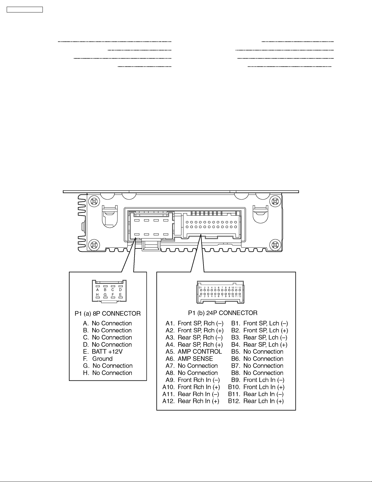
2 REAR VIEW AND CONNECTORS
5
8
9
11
2
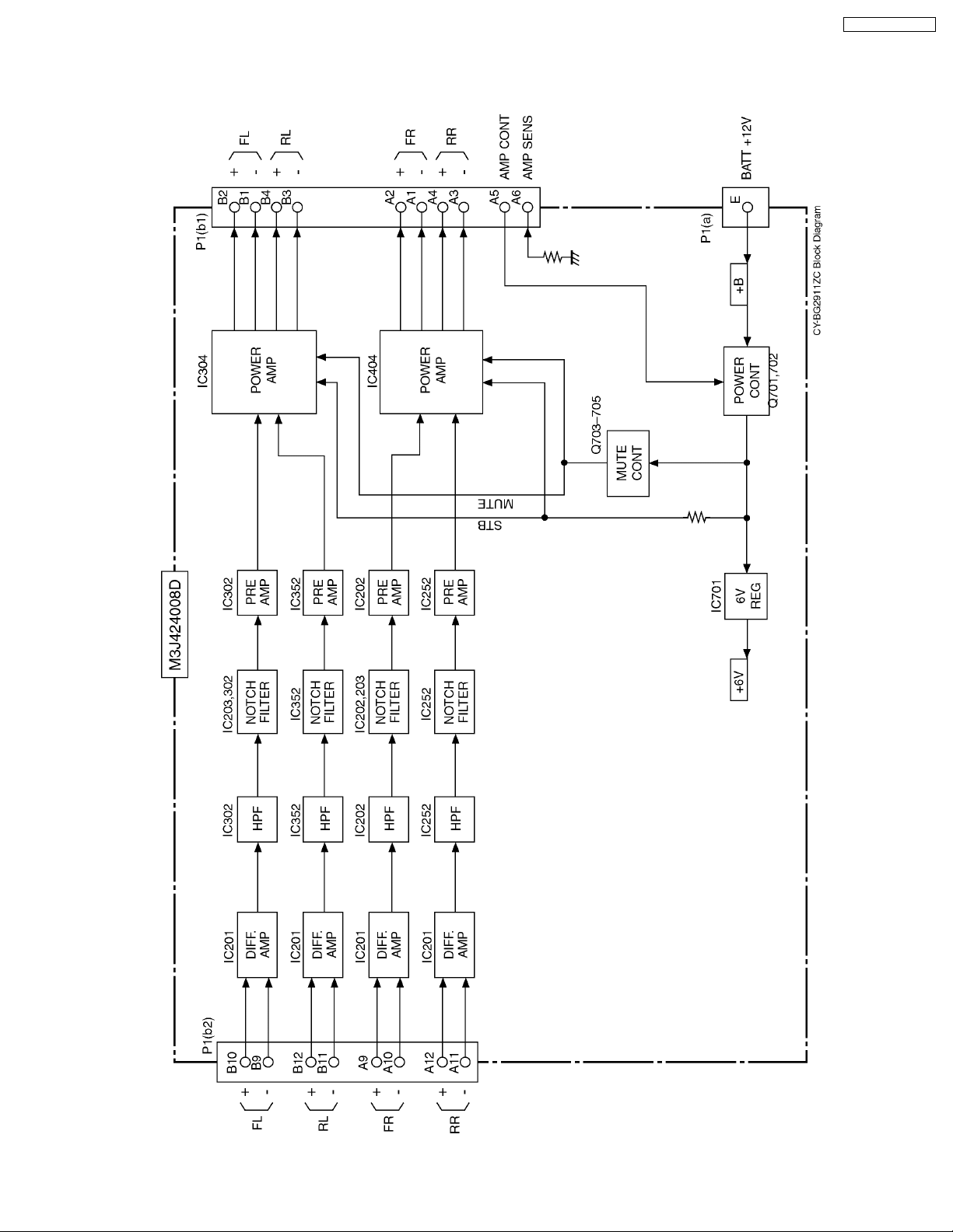
3 BLOCK DIAGRAM
3.1. Main Block
GM / CY-BG2911ZC
3
GM / CY-BG2911ZC
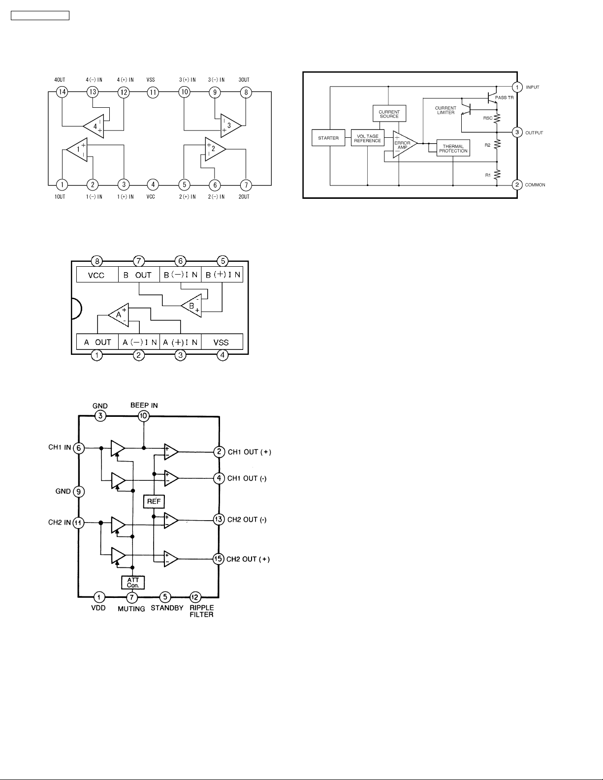
4 PACKAGE AND IC BLOCK DIAGRAM
4.1. MAIN BLOCK
IC201, 202, 252 : YEAMPC4574E1
IC302, 352 : YEAMPC4574E1
IC203, 205 : YEAMPC4570E1
IC701 : MC7806BT
IC204, 304 : AN7190NK
4
 Loading...