

Panasonic CU-E9LKE-3, CS-E7LKEW, CU-E12LKE, CU-E12LKE-3, CS-E15LKEW Service Manual
...
© Panasonic HA Air-Conditioning (M) Sdn. Bhd. 2010.
Unauthorized copying and distribution is a violation of law.
Order No. PHAAM1001023C2
Air Conditioner
Indoor Unit Outdoor Unit
CS-E7LKEW CU-E7LKE
CS-E7LKEW CU-E7LKE-3
CS-E9LKEW CU-E9LKE
CS-E9LKEW CU-E9LKE-3
CS-E12LKEW CU-E12LKE
CS-E12LKEW CU-E12LKE-3
CS-E15LKEW CU-E15LKE
CS-E18LKEW CU-E18LKE
CS-E21LKEW CU-E21LKE
CS-XE7LKEW CU-E7LKE
CS-XE7LKEW CU-E7LKE-3
CS-XE9LKEW CU-E9LKE
CS-XE9LKEW CU-E9LKE-3
CS-XE12LKEW CU-E12LKE
CS-XE12LKEW CU-E12LKE-3
CS-XE15LKEW CU-E15LKE
CS-XE18LKEW CU-E18LKE
CS-XE21LKEW CU-E21LKE
Please file and use this manual together with the service manual for Model No. CU-2E18CBPG, CU-3E23CBPG, CU4E27CBPG, Order No. RAC0209005C2, Model No. CU-3E18EBE, Order No. RAC0602011C2 and Model No. CU-2E15GBE,
Order No. MAC0704001A2.

2
TABLE OF CONTENTS
PAG E PAG E
1 Safety Precautions -----------------------------------------------3
2 Specifications ------------------------------------------------------5
3Features------------------------------------------------------------ 27
4 Location of Controls and Components------------------ 28
4.1. Indoor Unit ------------------------------------------------- 28
4.2. Outdoor Unit ----------------------------------------------- 28
4.3. Remote Control ------------------------------------------- 29
5 Dimensions ------------------------------------------------------- 30
5.1. Indoor Unit ------------------------------------------------- 30
5.2. Outdoor Unit ----------------------------------------------- 32
6 Refrigeration Cycle Diagram -------------------------------- 33
6.1. CU-E7LKE CU-E9LKE CU-E12LKE CUE15LKE----------------------------------------------------- 33
6.2. CU-E7LKE-3 CU-E9LKE-3 CU-E12LKE-3 ------- 34
6.3. CU-E18LKE CU-E21LKE ----------------------------- 35
7 Block Diagram --------------------------------------------------- 36
7.1. CU-E7LKE CU-E9LKE CU-E15LKE --------------- 36
7.2. CU-E12LKE------------------------------------------------ 37
7.3. CU-E7LKE-3 CU-E9LKE-3 CU-E12LKE-3 ------- 38
7.4. CU-E18LKE CU-E21LKE ----------------------------- 39
8 Wiring Connection Diagram --------------------------------- 40
8.1. Indoor Unit ------------------------------------------------- 40
8.2. Outdoor Unit ----------------------------------------------- 42
9 Electronic Circuit Diagram----------------------------------- 46
9.1. Indoor Unit ------------------------------------------------- 46
9.2. Outdoor Unit ----------------------------------------------- 48
10 Printed Circuit Board ------------------------------------------52
10.1. Indoor Unit ------------------------------------------------- 52
10.2. Outdoor Unit ----------------------------------------------- 55
11 Installation Instruction ----------------------------------------58
11.1. Select the Best Location ------------------------------- 58
11.2. Indoor Unit ------------------------------------------------- 59
11.3. Outdoor Unit ----------------------------------------------- 62
12 Operation and Control----------------------------------------- 65
12.1. Basic Function --------------------------------------------65
12.2. Indoor Fan Motor Operation --------------------------- 66
12.3. Outdoor Fan Motor Operation------------------------- 67
12.4. Airflow Direction ------------------------------------------ 67
12.5. Quiet operation (Cooling Mode/Cooling area
of Dry Mode)----------------------------------------------- 69
12.6. Quiet operation (Heating) ------------------------------ 69
12.7. Powerful Mode Operation ------------------------------ 70
12.8. Timer Control---------------------------------------------- 70
12.9. Auto Restart Control------------------------------------- 70
12.10. Indication Panel------------------------------------------- 70
12.11. Patrol Operation ------------------------------------------ 71
12.12. e-ion Operation -------------------------------------------73
12.13. Mild Dry Cooling Operation ---------------------------- 75
12.14. ECO Patrol Operation----------------------------------- 76
13 Operation Control (For Multi Split Connection)------- 80
13.1. Cooling operation ---------------------------------------- 80
13.2. Soft Dry Operation --------------------------------------- 80
13.3. Heating Operation---------------------------------------- 80
13.4. Automatic Operation------------------------------------- 80
13.5. Indoor Fan Motor Operation --------------------------- 81
13.6. Powerful Mode Operation ------------------------------ 81
13.7. Auto restart control--------------------------------------- 81
13.8. Indication Panel------------------------------------------- 81
13.9. Mild Dry Cooling Operation --------------------------- 81
14 Protection Control---------------------------------------------- 82
14.1. Protection Control For All Operations -------------- 82
14.2. Protection Control For Cooling & Soft Dry
Operation -------------------------------------------------- 84
14.3. Protection Control For Heating Operation --------- 85
15 Servicing Mode-------------------------------------------------- 87
15.1. Auto OFF/ON Button ----------------------------------- 87
15.2. Remote Control Button --------------------------------- 88
16 Troubleshooting Guide --------------------------------------- 89
16.1. Refrigeration Cycle System --------------------------- 89
16.2. Breakdown Self Diagnosis Function ---------------- 91
16.3. Error Codes Table --------------------------------------- 92
16.4. Self-diagnosis Method---------------------------------- 94
17 Disassembly and Assembly Instructions ------------- 124
17.1. CS-E7LK CS-E9LK CS-E12LK CS-E15LK ----124
17.2. CS-E18LK CS-E21LK -------------------------------- 128
17.3. Outdoor Electronic Controller Removal
Procedure-------------------------------------------------133
18 Technical Data --------------------------------------------------135
18.1. Operation Characteristics ---------------------------- 135
18.2. Sensible Capacity Chart ------------------------------171
19 Exploded View and Replacement Parts List---------- 173
19.1. Indoor Unit------------------------------------------------173
19.2. Outdoor Unit ---------------------------------------------181
3
1 Safety Precautions
• Read the following “SAFETY PRECAUTIONS” carefully before perform any servicing.
• Electrical work must be installed or serviced by a licensed electrician. Be sure to use the correct rating of the power plug and
main circuit for the model installed.
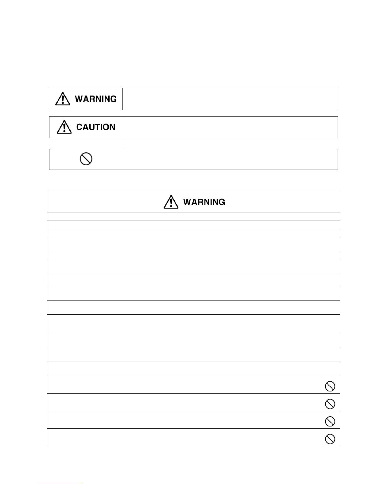
• The caution items stated here must be followed because these important contents are related to safety. The meaning of each
indication used is as below. Incorrect installation or servicing due to ignoring of the instruction will cause harm or damage, and
the seriousness is classified by the following indications.
• The items to be followed are classified by the symbols:
• Carry out test run to confirm that no abnormality occurs after the servicing. Then, explain to user the operation, care and
maintenance as stated in instructions. Please remind the customer to keep the operating instructions for future reference.
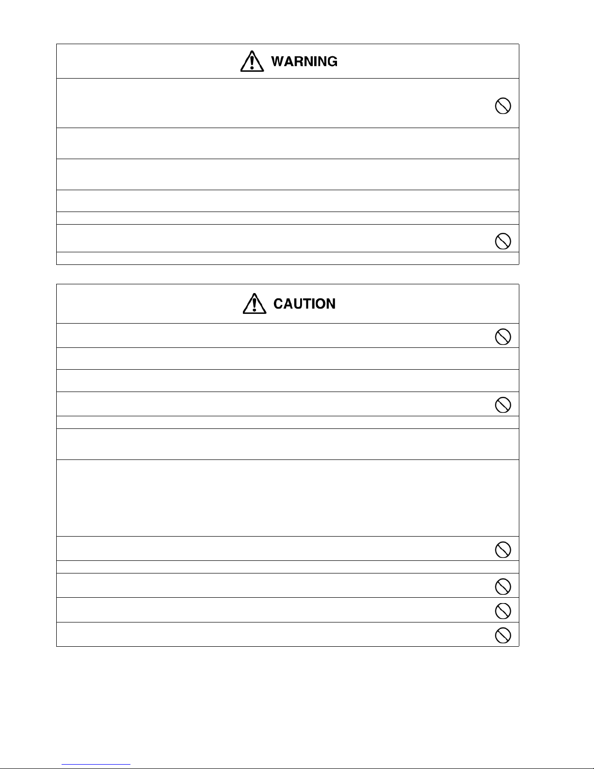
This indication shows the possibility of causing death or serious injury.
This indication shows the possibility of causing injury or damage to properties.
This symbol denotes item that is PROHIBITTED from doing.
1. Do not modify the machine, part, material during repairing service.
2. If wiring unit is supplied as repairing part, do not repair or connect the wire even only partial wire break. Exchange the whole wiring unit.
3. Do not wrench the fasten terminal. Pull it out or insert it straightly.
4. Engage authorized dealer or specialist for installation and servicing. If installation or servicing done by the user is defective, it will cause
water leakage, electrical shock or fire.
5. Install according to this installation instructions strictly. If installation is defective, it will cause water leakage, electrical shock or fire.
6. Use the attached accessories parts and specified parts for installation and servicing. Otherwise, it will cause the set to fall, water leakage,
fire or electrical shock.
7. Install at a strong and firm location which is able to withstand the set's weight. If the strength is not enough or installation is not properly
done, the set will drop and cause injury.
8. For electrical work, follow the local national wiring standard, regulation and the installation instruction. An independent circuit and single
outlet must be used. If electrical circuit capacity is not enough or defect found in electrical work, it will cause electrical shock or fire.
9. This equipment is strongly recommended to be installed with Earth Leakage Circuit Breaker (ELCB) or Residual Current Device (RCD).
Otherwise, it may cause electrical shock and fire in case equipment breakdown or insulation breakdown.
10. Do not use joint cable for indoor/outdoor connection cable. Use the specified indoor/outdoor connection cable, refer to installation
instruction CONNECT THE CABLE TO THE INDOOR UNIT and connect tightly for indoor/outdoor connection. Clamp the cable so that no
external force will be acted on the terminal. If connection or fixing is not perfect, it will cause heat up or fire at the connection.
11. Wire routing must be properly arranged so that control board cover is fixed properly. If control board cover is not fixed perfectly, it will cause
heat-up or fire at connection point of terminal, fire or electrical shock.
12. When install or relocate air conditioner, do not let any substance other than the specified refrigerant, eg. air etc. mix into refrigeration cycle
(piping). (Mixing of air etc. will cause abnormal high pressure in refrigeration cycle and result in explosion, injury etc.).
13. Do not install outdoor unit near handrail of veranda. When installing air-conditioner unit at veranda of high rise building, child may climb up
to outdoor unit and cross over the handrail and causing accident.
14. This equipment must be properly earthed. Earth line must not be connected to gas pipe, water pipe, earth of lightning rod and
telephone. Otherwise, it may cause electrical shock in case equipment breakdown or insulation breakdown.
15. Keep away from small children, the thin film may cling to nose and mouth and prevent breathing.
16. Do not use unspecified cord, modified cord, joint cord or extension cord for power supply cord. Do not share the single outlet
with other electrical appliances. Poor contact, poor insulation or over current will cause electrical shock or fire.
17. Tighten the flare nut with torque wrench according to specified method. If the flare nut is over-tightened, after a long period, the
flare may break and cause refrigerant gas leakage.
4
18. For R410A models, when connecting the piping, do not use any existing (R22) pipes and flare nuts. Using such same may
cause abnormally high pressure in the refrigeration cycle (piping), and possibly result in explosion and injury. Use only R410A
materials.
Thickness of copper pipes used with R410A must be more than 0.8mm. Never use copper pipes thinner than 0.8mm.
It is desirable that the amount of residual oil is less than 40 mg/10m.
19. During installation, install the refrigerant piping properly before run the compressor. (Operation of compressor without fixing refrigeration
piping and valves at opened condition will cause suck-in of air, abnormal high pressure in refrigeration cycle and result in explosion, injury
etc.).
20. During pump down operation, stop the compressor before remove the refrigeration piping. (Removal of refrigeration piping while
compressor is operating and valves are opened condition will cause suck-in of air, abnormal high pressure in refrigeration cycle and result
in explosion, injury etc.).
21. After completion of installation or service, confirm there is no leakage of refrigerant gas. It may generate toxic gas when the refrigerant
contacts with fire.
22. Ventilate if there is refrigerant gas leakage during operation. It may cause toxic gas when the refrigerant contacts with fire.
23. Do not insert your fingers or other objects into the unit, high speed rotating fan may cause injury.
24. Must not use other parts except original parts describe in catalog and manual.
1. Do not install the unit at place where leakage of flammable gas may occur. In case gas leaks and accumulates at surrounding of
the unit, it may cause fire.
2. Carry out drainage piping as mentioned in installation instructions. If drainage is not perfect, water may enter the room and damage the
furniture.
3. Tighten the flare nut with torque wrench according to specified method. If the flare nut is over-tightened, after a long period, the flare may
break and cause refrigerant gas leakage.
4. Do not touch outdoor unit air inlet and aluminium fin. It may cause injury.
5. Select an installation location which is easy for maintenance.
6. Pb free solder has a higher melting point than standard solder; typically the melting point is 50°F - 70°F (30°C - 40°C) higher. Please use a
high temperature solder iron. In case of the soldering iron with temperature control, please set it to 700 ± 20°F (370 ± 10°C). Pb free solder
will tend to splash when heated too high (about 1100°F / 600°C).
7. Power supply connection to the air conditioner. Connect the power supply cord of the air conditioner to the mains using one of the following
methods.
Power supply point shall be the place where there is ease for access for the power disconnection in case of emergency. In some countries,
permanent connection of this room air conditioner to the power supply is prohibited.
i. Power supply connection to the receptacle using a power plug. Use an approved 15/16A (3/4~1.75HP), 16A (2.0HP), 20A (2.5HP) or
25A (3.0HP) power plug with earth pin for the connection to the socket.
ii. Power supply connection to a circuit breaker for the permanent connection. Use an approved 16A (3/4~2.0HP), 20A (2.5HP) or 25A
(3.0HP) circuit breaker for the permanent connection. It must be a double pole switch with a minimum 3.0 mm contact gap.
8. Do not release refrigerant during piping work for installation, servicing, reinstallation and during repairing a refrigerant parts.
Take care of the liquid refrigerant, it may cause frostbite.
9. Installation or servicing work: It may need two people to carry out the installation or servicing work.
10. Do not install this appliance in a laundry room or other location where water may drip from the ceiling, etc.
11. Do not sit or step on the unit, you may fall down accidentally.
12. Do not touch the sharp aluminium fin, sharp parts may cause injury.
5
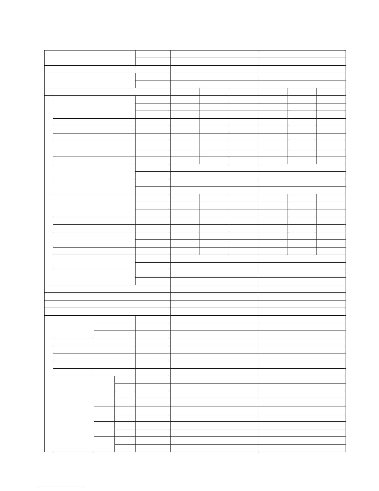
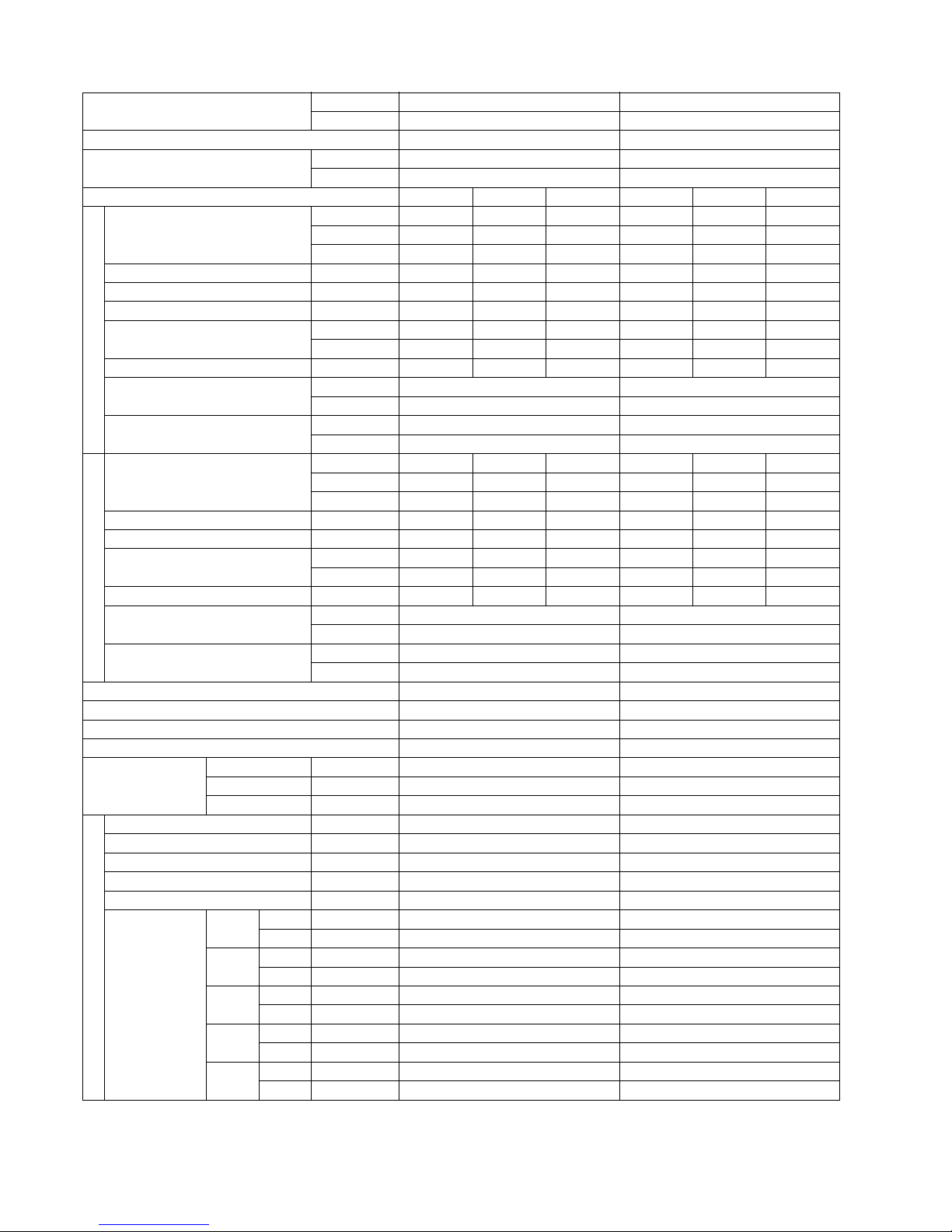
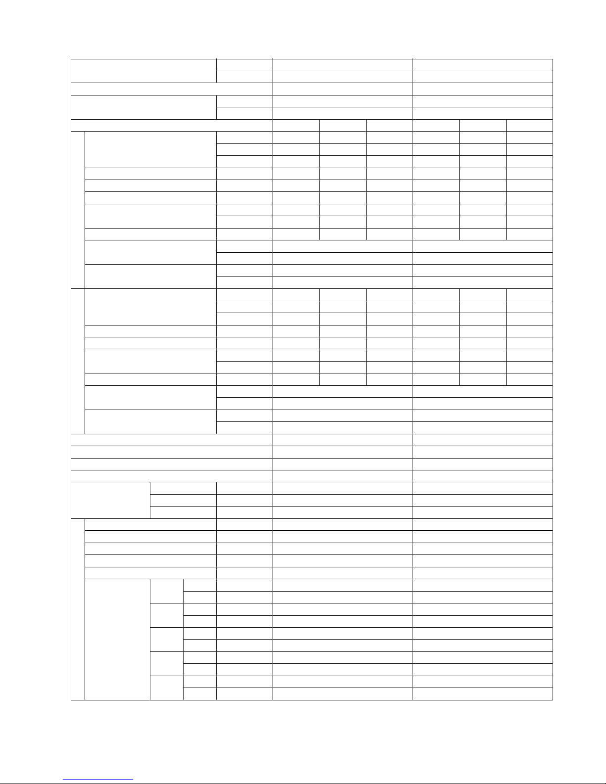
2 Specifications
MODEL INDOOR CS-E7LKEW, CS-XE7LKEW CS-E9LKEW, CS-XE9LKEW
OUTDOOR CU-E7LKE CU-E9LKE
Performance Test Condition EUROVENT EUROVENT
Power Supply
Phase, Hz Single, 50 Single, 50
V 230 230
Min. Mid. Max. Min. Mid. Max.
Cooling
Capacity
kW 0.70 2.05 2.40 0.80 2.50 3.00
BTU/h 2390 6990 8180 2730 8530 10200
Kcal/h 600 1760 2060 690 2150 2580
Running Current A — 2.2 — — 2.5 —
Input Power W 170 470 580 175 535 730
Annual Consumption kWh — 235 — — 268 —
EER
W/W 4.12 4.36 4.14 4.57 4.67 4.11
Kcal/hW 3.53 3.74 3.55 3.94 4.02 3.53
Power Factor % — 93 — — 93 —
Indoor Noise (H / L / QLo)
dB-A 37 / 24 / 20 39 / 25 / 20
Power Level dB 53 / 40 / 36 55 / 41 / 36
Outdoor Noise (H / L)
dB-A 45 / - 46 / -
Power Level dB 60 / - 61 / -
Heating
Capacity
kW 0.70 2.80 4.00 0.80 3.40 5.00
BTU/h 2390 9550 13600 2730 11600 17100
Kcal/h 600 2410 3440 690 2920 4300
Running Current A — 3.0 — — 3.4 —
Input Power W 160 635 1.02k 165 735 1.30k
COP
W/W 4.38 4.41 3.92 4.85 4.63 3.85
Kcal/hW 3.75 3.80 3.37 4.18 3.97 3.31
Power Factor % — 92 — — 94 —
Indoor Noise (H / L / QLo)
dB-A 38 / 25 / 20 40 / 27 / 20
Power Level dB 54 / 41 / 36 56 / 43 / 36
Outdoor Noise (H / L)
dB-A 46 / - 47 / -
Power Level dB 61 / - 62 / -
Low Temp. : Capacity (kW) / I.Power (W) / COP 2.90 / 900 / 3.22 3.62 / 1.15k / 3.15
Extr Low Temp. : Capacity (kW) / I.Power (W) / COP 2.35 / 930 / 2.53 2.88 / 1.18k / 2.44
Max Current (A) / Max Input Power (W) 4.7 / 1.02k 5.8 / 1.30k
Starting Current (A) 3.0 3.4
Compressor
Type Hermetic Motor Hermetic Motor
Motor Type Brushless (6-poles) Brushless (6-poles)
Output Power W 650 700
Indoor Fan
Type Cross-flow Fan Cross-flow Fan
Material ASG20K1 ASG20K1
Motor Type Transistor (8-poles) Transistor (8-poles)
Input Power W — —
Output Power W 40 40
Speed
QLo
Cool rpm 590 630
Heat rpm 630 670
Lo
Cool rpm 670 730
Heat rpm 730 820
Me
Cool rpm 860 950
Heat rpm 910 1030
Hi
Cool rpm 1050 1180
Heat rpm 1090 1240
SHi
Cool rpm 1110 1240
Heat rpm 1150 1280
6
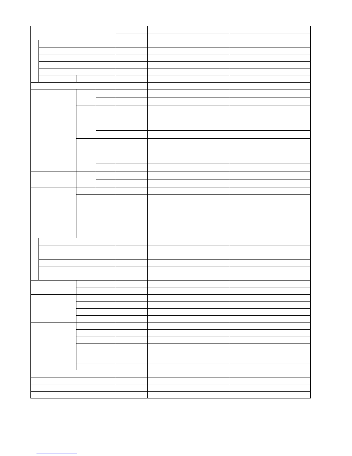
Outdoor Fan
Type Propeller Fan Propeller Fan
Material PP PP
Motor Type Induction (6-poles) Induction (6-poles)
Input Power W 62 65
Output Power W 25 25
Speed Hi rpm 770 770
Moisture Removal L/h (Pt/h) 1.3 (2.7) 1.5 (3.2)
Indoor Airflow
QLo
Cool
m
3
/min (ft3/min)
5.6 (198) 4.9 (173)
Heat
m
3
/min (ft3/min)
6.0 (212) 5.3 (187)
Lo
Cool
m
3
/min (ft3/min)
6.5 (230) 6.0 (212)
Heat
m
3
/min (ft3/min)
7.2 (254) 7.1 (251)
Me
Cool
m
3
/min (ft3/min)
8.7 (307) 8.7 (307)
Heat
m
3
/min (ft3/min)
9.3 (328) 9.6 (339)
Hi
Cool
m
3
/min (ft3/min)
10.9 (385) 11.3 (400)
Heat
m
3
/min (ft3/min)
11.4 (400) 11.7 (410)
SHi
Cool
m
3
/min (ft3/min)
11.6 (410) 11.7 (410)
Heat
m
3
/min (ft3/min)
12.0 (424) 12.1 (427)
Outdoor Airflow Hi
Cool
m
3
/min (ft3/min)
33.9 (1200) 29.8 (1050)
Heat
m
3
/min (ft3/min)
33.9 (1200) 29.8 (1050)
Refrigeration Cycle
Control Device Check Valve & Capillary Tube Check Valve & Capillary Tube
Refrigerant Oil
cm
3
RB68A or Freol Alpha 68M (320) RB68A or Freol Alpha 68M (320)
Refrigerant Type g (oz) R410A, 830 (29.3) R410A, 950 (33.5)
Dimension Height (I/D / O/D) mm (inch) 290 (11-7/16) / 540 (21-9/32) 290 (11-7/16) / 540 (21-9/32)
Width (I/D / O/D) mm (inch) 870 (34-9/32) / 780 (30-23/32) 870 (34-9/32) / 780 (30-23/32)
Depth (I/D / O/D) mm (inch) 204 (8-1/16) / 289 (11-13/32) 204 (8-1/16) / 289 (11-13/32)
Weight Net (I/D / O/D) kg (lb) 9 (20) / 33 (73) 9 (20) / 34 (75)
Piping
Pipe Diameter (Liquid / Gas) mm (inch) 6.35 (1/4) / 9.52 (3/8) 6.35 (1/4) / 9.52 (3/8)
Standard Length m (ft) 5 (16.4) 5 (16.4)
Length Range (min - max) m (ft) 3 (9.8) ~ 15 (49.2) 3 (9.8) ~ 15 (49.2)
I/D & O/D Height Different m (ft) 15.0 (49.2) 15.0 (49.2)
Additional Gas Amount g/m (oz/ft) 20 (0.2) 20 (0.2)
Length for Additional Gas m (ft) 7.5 (24.6) 7.5 (24.6)
Drain Hose
Inner Diameter mm 16 16
Length mm 650 650
Indoor Heat
Exchanger
Fin Material Aluminium (Pre Coat) Aluminium (Pre Coat)
Fin Type Slit Fin Slit Fin
Row x Stage x FPI 2 x 15 x 17 2 x 15 x 21
Size (W x H x L) mm 610 x 315 x 25.4 610 x 315 x 25.4
Outdoor Heat
Exchanger
Fin Material Aluminium Aluminium
Fin Type Corrugated Fin Corrugated Fin
Row x Stage x FPI 1 x 20 x 19 2 x 24 x 17
Size (W x H x L) mm
22 x 508 x 708.4
36.4 x 504 x 713
684
Air Filter
Material Polypropelene Polypropelene
Type One-touch One-touch
Power Supply Outdoor Power Supply Outdoor Power Supply
Power Supply Cord A Nil Nil
Thermostat Electronic Control Electronic Control
Protection Device Electronic Control Electronic Control
MODEL INDOOR CS-E7LKEW, CS-XE7LKEW CS-E9LKEW, CS-XE9LKEW
OUTDOOR CU-E7LKE CU-E9LKE
7
1. Cooling capacities are based on indoor temperature of 27°C Dry Bulb (80.6°F Dry Bulb), 19.0°C Wet Bulb (66.2°F Wet Bulb)
and outdoor air temperature of 35°C Dry Bulb (95°F Dry Bulb), 24°C Wet Bulb (75.2°F Wet Bulb)
2. Heating capacities are based on indoor temperature of 20°C Dry Bulb (68°F Dry Bulb) and outdoor air temperature of 7°C Dry
Bulb (44.6°F Dry Bulb), 6°C Wet Bulb (42.8°F Wet Bulb)
3. Heating low temperature capacity, Input Power and COP measured at 230 V, indoor temperature 20°C, outdoor 2/1°C
4. Heating extreme low temperature capacity, Input Power and COP measured at 230 V, indoor temperature 20°C, outdoor
-7/-8°C
5. Specifications are subjected to change without prior notice for further improvement.
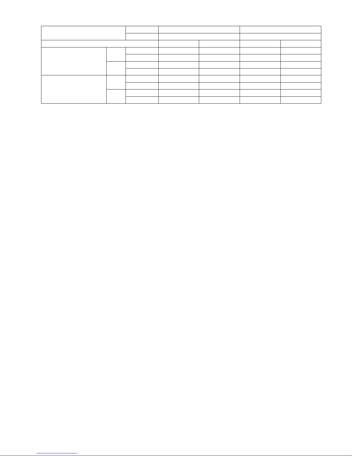
Dry Bulb Wet Bulb Dry Bulb Wet Bulb
Indoor Operation Range
Cooling Maximum 32 23 32 23
Minimum 16 11 16 11
Heating Maximum 30 — 30 —
Minimum 16 — 16 —
Outdoor Operation Range
Cooling Maximum 43 26 43 26
Minimum 5 4 5 4
Heating Maximum 24 18 24 18
Minimum -5 -6 -5 -6
MODEL INDOOR CS-E7LKEW, CS-XE7LKEW CS-E9LKEW, CS-XE9LKEW
OUTDOOR CU-E7LKE CU-E9LKE
8
MODEL INDOOR CS-E12LKEW, CS-XE12LKEW CS-E15LKEW, CS-XE15LKEW
OUTDOOR CU-E12LKE CU-E15LKE
Performance Test Condition EUROVENT EUROVENT
Power Supply
Phase, Hz Single, 50 Single, 50
V 230 230
Min. Mid. Max. Min. Mid. Max.
Cooling
Capacity
kW 0.80 3.50 4.00 0.80 4.20 5.00
BTU/h 2730 11900 13600 2730 14300 17100
Kcal/h 690 3010 3440 690 3610 4300
Running Current A — 3.9 — — 5.7 —
Input Power W 185 860 1.13k 195 1.26k 1.57k
Annual Consumption kWh — 430 — — 630 —
EER
W/W 4.32 4.07 3.54 4.10 3.33 3.18
Kcal/hW 3.73 3.50 3.04 3.54 2.87 2.74
Power Factor % — 96 — — 96 —
Indoor Noise (H / L / QLo)
dB-A 42 / 28 / 20 43 / 31 / 25
Power Level dB 58 / 44 / 36 59 / 47 / 41
Outdoor Noise (H / L)
dB-A 48 / - 49 / -
Power Level dB 63 / - 64 / -
Heating
Capacity
kW 0.80 4.00 6.00 0.80 5.30 6.80
BTU/h 2730 13600 20500 2730 18100 23200
Kcal/h 690 3440 5160 690 4560 5850
Running Current A — 4.4 — — 6.6 —
Input Power W 175 950 1.71k 185 1.44k 1.94k
COP
W/W 4.57 4.21 3.51 4.32 3.68 3.51
Kcal/hW 3.94 3.62 3.02 3.73 3.17 3.02
Power Factor % — 94 — — 95 —
Indoor Noise (H / L / QLo)
dB-A 42 / 33 / 20 43 / 35 / 29
Power Level dB 58 / 49 / 36 59 / 51 / 45
Outdoor Noise (H / L)
dB-A 50 / - 51 / -
Power Level dB 65 / - 66 / -
Low Temp. : Capacity (kW) / I.Power (W) / COP 4.47 / 1.48k / 3.02 4.92 / 1.72k / 2.86
Extr Low Temp. : Capacity (kW) / I.Power (W) / COP 3.46 / 1.49k / 2.32 3.94 / 1.83k / 2.15
Max Current (A) / Max Input Power (W) 7.8 / 1.71k 9.0 / 1.94k
Starting Current (A) 4.4 6.6
Compressor
Type Hermetic Motor Hermetic Motor
Motor Type Brushless (4-poles) Brushless (6-poles)
Output Power W 700 700
Indoor Fan
Type Cross-flow Fan Cross-flow Fan
Material ASG20K1 ASG20K1
Motor Type Transistor (8-poles) Transistor (8-poles)
Input Power W — —
Output Power W 40 40
Speed
QLo
Cool rpm 630 730
Heat rpm 670 900
Lo
Cool rpm 830 870
Heat rpm 1010 1080
Me
Cool rpm 1040 1070
Heat rpm 1150 1210
Hi
Cool rpm 1260 1270
Heat rpm 1300 1350
SHi
Cool rpm 1320 1340
Heat rpm 1340 1370
9
Outdoor Fan
Type Propeller Fan Propeller Fan
Material PP PP
Motor Type DC Motor (8-poles) Induction (6-poles)
Input Power W — 70
Output Power W 40 30
Speed Hi rpm 830 850
Moisture Removal L/h (Pt/h) 2.0 (4.2) 2.4 (5.1)
Indoor Airflow
QLo
Cool
m
3
/min (ft3/min)
4.9 (173) 6.0 (212)
Heat
m
3
/min (ft3/min)
5.3 (187) 8.1 (286)
Lo
Cool
m
3
/min (ft3/min)
7.2 (254) 7.7 (272)
Heat
m
3
/min (ft3/min)
9.4 (332) 10.2 (360)
Me
Cool
m
3
/min (ft3/min)
9.7 (343) 10.1 (357)
Heat
m
3
/min (ft3/min)
11.0 (389) 11.7 (413)
Hi
Cool
m
3
/min (ft3/min)
12.5 (440) 12.5 (440)
Heat
m
3
/min (ft3/min)
12.8 (450) 13.4 (475)
SHi
Cool
m
3
/min (ft3/min)
13.1 (463) 13.3 (470)
Heat
m
3
/min (ft3/min)
13.3 (470) 13.6 (480)
Outdoor Airflow Hi
Cool
m
3
/min (ft3/min)
31.0 (1090) 31.4 (1110)
Heat
m
3
/min (ft3/min)
31.0 (1090) 31.4 (1110)
Refrigeration Cycle
Control Device Check Valve & Capillary Tube Check Valve & Capillary Tube
Refrigerant Oil
cm
3
RB68A or Freol Alpha 68M (320) RB68A or Freol Alpha 68M (400)
Refrigerant Type g (oz) R410A, 980 (34.6) R410A, 1.01k (35.7)
Dimension Height (I/D / O/D) mm (inch) 290 (11-7/16) / 540 (21-9/32) 290 (11-7/16) / 540 (21-9/32)
Width (I/D / O/D) mm (inch) 870 (34-9/32) / 780 (30-23/32) 870 (34-9/32) / 780 (30-23/32)
Depth (I/D / O/D) mm (inch) 204 (8-1/16) / 289 (11-13/32) 204 (8-1/16) / 289 (11-13/32)
Weight Net (I/D / O/D) kg (lb) 9 (20) / 34 (75) 9 (20) / 34 (75)
Piping
Pipe Diameter (Liquid / Gas) mm (inch) 6.35 (1/4) / 9.52 (3/8) 6.35 (1/4) / 12.70 (1/2)
Standard Length m (ft) 5 (16.4) 5 (16.4)
Length Range (min - max) m (ft) 3 (9.8) ~ 15 (49.2) 3 (9.8) ~ 15 (49.2)
I/D & O/D Height Different m (ft) 15.0 (49.2) 15.0 (49.2)
Additional Gas Amount g/m (oz/ft) 20 (0.2) 20 (0.2)
Length for Additional Gas m (ft) 7.5 (24.6) 7.5 (24.6)
Drain Hose
Inner Diameter mm 16 16
Length mm 650 650
Indoor Heat
Exchanger
Fin Material Aluminium (Pre Coat) Aluminium (Pre Coat)
Fin Type Slit Fin Slit Fin
Row x Stage x FPI 2 x 15 x 21 2 x 15 x 21
Size (W x H x L) mm 610 x 315 x 25.4 610 x 315 x 25.4
Outdoor Heat
Exchanger
Fin Material Aluminium Aluminium
Fin Type Corrugated Fin Corrugated Fin
Row x Stage x FPI 2 x 24 x 17 2 x 24 x 17
Size (W x H x L) mm
36.4 x 504 x 713
684
36.4 x 504 x 713
684
Air Filter
Material Polypropelene Polypropelene
Type One-touch One-touch
Power Supply Outdoor Power Supply Outdoor Power Supply
Power Supply Cord A Nil Nil
Thermostat Electronic Control Electronic Control
Protection Device Electronic Control Electronic Control
MODEL INDOOR CS-E12LKEW, CS-XE12LKEW CS-E15LKEW, CS-XE15LKEW
OUTDOOR CU-E12LKE CU-E15LKE
10
1. Cooling capacities are based on indoor temperature of 27°C Dry Bulb (80.6°F Dry Bulb), 19.0°C Wet Bulb (66.2°F Wet Bulb)
and outdoor air temperature of 35°C Dry Bulb (95°F Dry Bulb), 24°C Wet Bulb (75.2°F Wet Bulb)
2. Heating capacities are based on indoor temperature of 20°C Dry Bulb (68°F Dry Bulb) and outdoor air temperature of 7°C Dry
Bulb (44.6°F Dry Bulb), 6°C Wet Bulb (42.8°F Wet Bulb)
3. Heating low temperature capacity, Input Power and COP measured at 230 V, indoor temperature 20°C, outdoor 2/1°C
4. Heating extreme low temperature capacity, Input Power and COP measured at 230 V, indoor temperature 20°C, outdoor
-7/-8°C
5. Specifications are subjected to change without prior notice for further improvement.
Dry Bulb Wet Bulb Dry Bulb Wet Bulb
Indoor Operation Range
Cooling Maximum 32 23 32 23
Minimum 16 11 16 11
Heating Maximum 30 — 30 —
Minimum 16 — 16 —
Outdoor Operation Range
Cooling Maximum 43 26 43 26
Minimum 5 4 5 4
Heating Maximum 24 18 24 18
Minimum -5 -6 -5 -6
MODEL INDOOR CS-E12LKEW, CS-XE12LKEW CS-E15LKEW, CS-XE15LKEW
OUTDOOR CU-E12LKE CU-E15LKE
11
MODEL INDOOR CS-E7LKEW, CS-XE7LKEW CS-E9LKEW, CS-XE9LKEW
OUTDOOR CU-E7LKE-3 CU-E9LKE-3
Performance Test Condition EUROVENT EUROVENT
Power Supply
Phase, Hz Single, 50 Single, 50
V 230 230
Min. Mid. Max. Min. Mid. Max.
Cooling
Capacity
kW 0.70 2.05 2.40 0.80 2.50 3.00
BTU/h 2390 6990 8180 2730 8530 10200
Kcal/h 600 1760 2060 690 2150 2580
Running Current A — 2.2 — — 2.5 —
Input Power W 170 470 580 175 535 730
Annual Consumption kWh — 235 — — 268 —
EER
W/W 4.12 4.36 4.14 4.57 4.67 4.11
Kcal/hW 3.53 3.74 3.55 3.94 4.02 3.53
Power Factor % — 93 — — 93 —
Indoor Noise (H / L / QLo)
dB-A 37 / 24 / 20 39 / 25 / 20
Power Level dB 53 / 40 / 36 55 / 41 / 36
Outdoor Noise (H / L)
dB-A 45 / - 46 / -
Power Level dB 60 / - 61 / -
Heating
Capacity
kW 0.70 2.80 4.00 0.80 3.40 5.00
BTU/h 2390 9550 13600 2730 11600 17100
Kcal/h 600 2410 3440 690 2920 4300
Running Current A — 3.0 — — 3.4 —
Input Power W 160 635 1.02k 165 735 1.30k
COP
W/W 4.38 4.41 3.92 4.85 4.63 3.85
Kcal/hW 3.75 3.80 3.37 4.18 3.97 3.31
Power Factor % — 92 — — 94 —
Indoor Noise (H / L / QLo)
dB-A 38 / 25 / 20 40 / 27 / 20
Power Level dB 54 / 41 / 36 56 / 43 / 36
Outdoor Noise (H / L)
dB-A 46 / - 47 / -
Power Level dB 61 / - 62 / -
Low Temp. : Capacity (kW) / I.Power (W) / COP 2.90 / 900 / 3.22 3.62 / 1.15k / 3.15
Extr Low Temp. : Capacity (kW) / I.Power (W) / COP 2.35 / 930 / 2.53 2.88 / 1.18k / 2.44
Max Current (A) / Max Input Power (W) 4.7 / 1.02k 5.8 / 1.30k
Starting Current (A) 3.0 3.4
Compressor
Type Hermetic Motor Hermetic Motor
Motor Type Brushless (6-poles) Brushless (6-poles)
Output Power W 650 700
Indoor Fan
Type Cross-flow Fan Cross-flow Fan
Material ASG20K1 ASG20K1
Motor Type Transistor (8-poles) Transistor (8-poles)
Input Power W — —
Output Power W 40 40
Speed
QLo
Cool rpm 590 630
Heat rpm 630 670
Lo
Cool rpm 670 730
Heat rpm 730 820
Me
Cool rpm 860 950
Heat rpm 910 1030
Hi
Cool rpm 1050 1180
Heat rpm 1090 1240
SHi
Cool rpm 1110 1240
Heat rpm 1150 1280

12
Outdoor Fan
Type Propeller Fan Propeller Fan
Material PP PP
Motor Type Induction (6-poles) Induction (6-poles)
Input Power W 62 65
Output Power W 25 25
Speed Hi rpm 770 770
Moisture Removal L/h (Pt/h) 1.3 (2.7) 1.5 (3.2)
Indoor Airflow
QLo
Cool
m
3
/min (ft3/min)
5.6 (198) 4.9 (173)
Heat
m
3
/min (ft3/min)
6.0 (212) 5.3 (187)
Lo
Cool
m
3
/min (ft3/min)
6.5 (230) 6.0 (212)
Heat
m
3
/min (ft3/min)
7.2 (254) 7.1 (251)
Me
Cool
m
3
/min (ft3/min)
8.7 (307) 8.7 (307)
Heat
m
3
/min (ft3/min)
9.3 (328) 9.6 (339)
Hi
Cool
m
3
/min (ft3/min)
10.9 (385) 11.3 (400)
Heat
m
3
/min (ft3/min)
11.4 (400) 11.7 (410)
SHi
Cool
m
3
/min (ft3/min)
11.6 (410) 11.7 (410)
Heat
m
3
/min (ft3/min)
12.0 (424) 12.1 (427)
Outdoor Airflow Hi
Cool
m
3
/min (ft3/min)
33.9 (1200) 29.8 (1050)
Heat
m
3
/min (ft3/min)
33.9 (1200) 29.8 (1050)
Refrigeration Cycle
Control Device Check Valve & Capillary Tube Check Valve & Capillary Tube
Refrigerant Oil
cm
3
RB68A or Freol Alpha 68M (320) RB68A or Freol Alpha 68M (320)
Refrigerant Type g (oz) R410A, 830 (29.3) R410A, 950 (33.5)
Dimension Height (I/D / O/D) mm (inch) 290 (11-7/16) / 540 (21-9/32) 290 (11-7/16) / 540 (21-9/32)
Width (I/D / O/D) mm (inch) 870 (34-9/32) / 780 (30-23/32) 870 (34-9/32) / 780 (30-23/32)
Depth (I/D / O/D) mm (inch) 204 (8-1/16) / 289 (11-13/32) 204 (8-1/16) / 289 (11-13/32)
Weight Net (I/D / O/D) kg (lb) 9 (20) / 33 (73) 9 (20) / 34 (75)
Piping
Pipe Diameter (Liquid / Gas) mm (inch) 6.35 (1/4) / 9.52 (3/8) 6.35 (1/4) / 9.52 (3/8)
Standard Length m (ft) 5 (16.4) 5 (16.4)
Length Range (min - max) m (ft) 3 (9.8) ~ 15 (49.2) 3 (9.8) ~ 15 (49.2)
I/D & O/D Height Different m (ft) 15.0 (49.2) 15.0 (49.2)
Additional Gas Amount g/m (oz/ft) 20 (0.2) 20 (0.2)
Length for Additional Gas m (ft) 7.5 (24.6) 7.5 (24.6)
Drain Hose
Inner Diameter mm 16 16
Length mm 650 650
Indoor Heat
Exchanger
Fin Material Aluminium (Pre Coat) Aluminium (Pre Coat)
Fin Type Slit Fin Slit Fin
Row x Stage x FPI 2 x 15 x 17 2 x 15 x 21
Size (W x H x L) mm 610 x 315 x 25.4 610 x 315 x 25.4
Outdoor Heat
Exchanger
Fin Material Aluminium Aluminium
Fin Type Corrugated Fin Corrugated Fin
Row x Stage x FPI 1 x 20 x 19 2 x 24 x 17
Size (W x H x L) mm
32 x 508 x 708 36.4 x 504 x 713
684
Air Filter
Material Polypropelene Polypropelene
Type One-touch One-touch
Power Supply Outdoor Power Supply Outdoor Power Supply
Power Supply Cord A Nil Nil
Thermostat Electronic Control Electronic Control
Protection Device Electronic Control Electronic Control
MODEL INDOOR CS-E7LKEW, CS-XE7LKEW CS-E9LKEW, CS-XE9LKEW
OUTDOOR CU-E7LKE-3 CU-E9LKE-3

13
1. Cooling capacities are based on indoor temperature of 27°C Dry Bulb (80.6°F Dry Bulb), 19.0°C Wet Bulb (66.2°F Wet Bulb)
and outdoor air temperature of 35°C Dry Bulb (95°F Dry Bulb), 24°C Wet Bulb (75.2°F Wet Bulb)
2. Heating capacities are based on indoor temperature of 20°C Dry Bulb (68°F Dry Bulb) and outdoor air temperature of 7°C Dry
Bulb (44.6°F Dry Bulb), 6°C Wet Bulb (42.8°F Wet Bulb)
3. Heating low temperature capacity, Input Power and COP measured at 230 V, indoor temperature 20°C, outdoor 2/1°C
4. Heating extreme low temperature capacity, Input Power and COP measured at 230 V, indoor temperature 20°C, outdoor
-7/-8°C
5. Specifications are subjected to change without prior notice for further improvement.
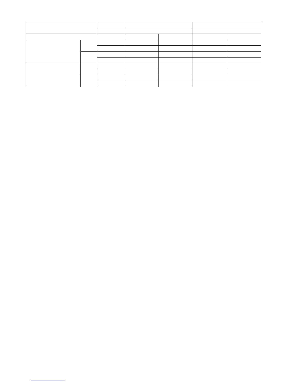
Dry Bulb Wet Bulb Dry Bulb Wet Bulb
Indoor Operation Range
Cooling Maximum 32 23 32 23
Minimum 16 11 16 11
Heating Maximum 30 — 30 —
Minimum 16 — 16 —
Outdoor Operation Range
Cooling Maximum 43 26 43 26
Minimum 5 4 5 4
Heating Maximum 24 18 24 18
Minimum -15 -16 -15 -16
MODEL INDOOR CS-E7LKEW, CS-XE7LKEW CS-E9LKEW, CS-XE9LKEW
OUTDOOR CU-E7LKE-3 CU-E9LKE-3
14
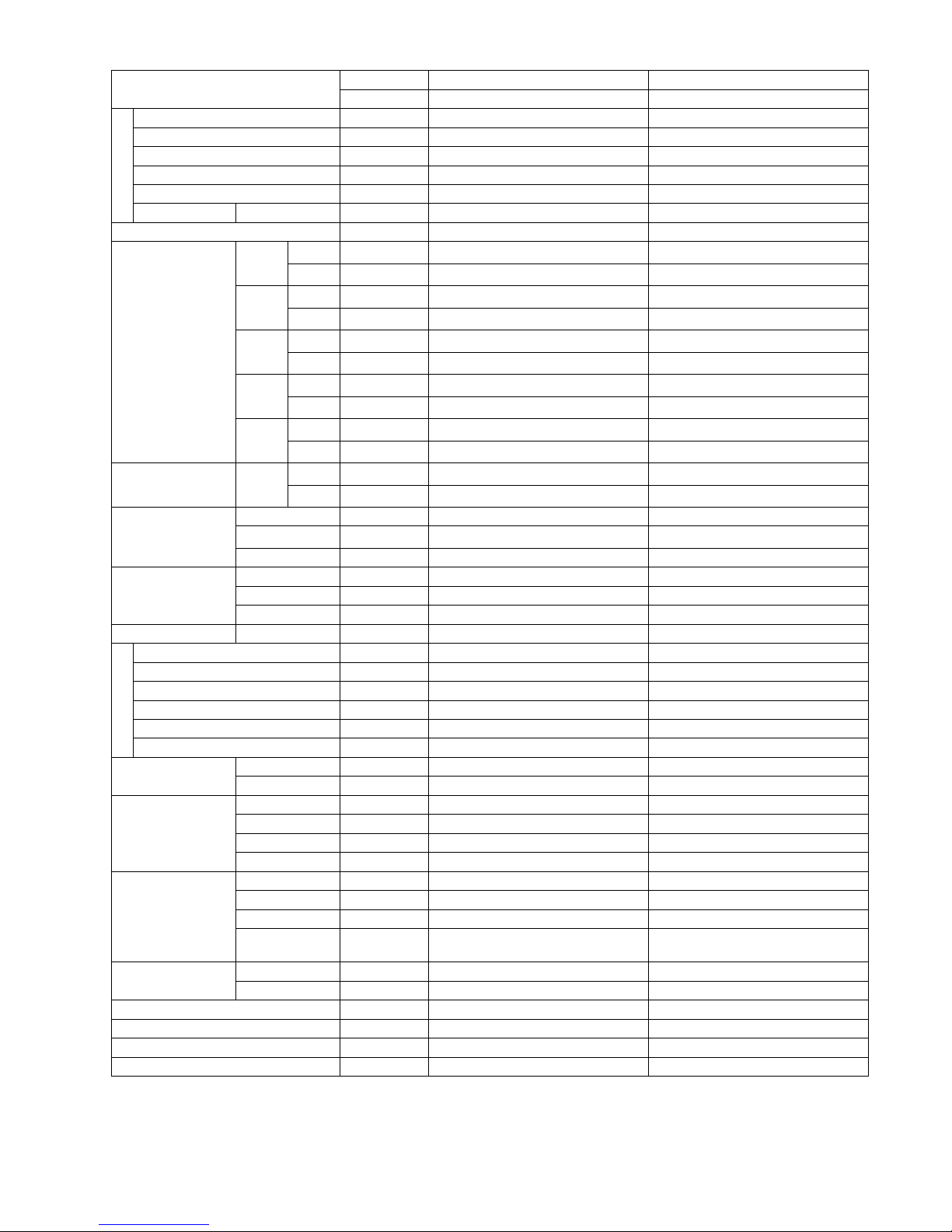
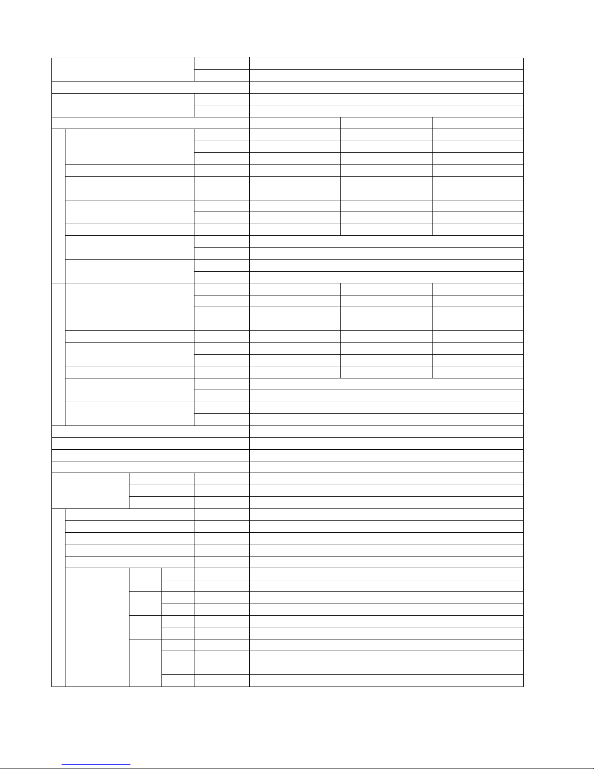
MODEL INDOOR CS-E12LKEW, CS-XE12LKEW
OUTDOOR CU-E12LKE-3
Performance Test Condition EUROVENT
Power Supply
Phase, Hz Single, 50
V 230
Min. Mid. Max.
Cooling
Capacity
kW 0.80 3.50 4.00
BTU/h 2730 11900 13600
Kcal/h 690 3010 3440
Running Current A — 4.1 —
Input Power W 185 905 1.18k
Annual Consumption kWh — 453 —
EER
W/W 4.32 3.87 3.39
Kcal/hW 3.73 3.33 2.92
Power Factor % — 96 —
Indoor Noise (H / L / QLo)
dB-A 42 / 28 / 20
Power Level dB 58 / 44 / 36
Outdoor Noise (H / L)
dB-A 48 / -
Power Level dB 63 / -
Heating
Capacity
kW 0.80 4.40 6.70
BTU/h 2730 15000 22800
Kcal/h 690 3780 5760
Running Current A — 5.1 —
Input Power W 175 1.09k 1.93k
COP
W/W 4.57 4.04 3.47
Kcal/hW 3.94 3.47 2.98
Power Factor % — 93 —
Indoor Noise (H / L / QLo)
dB-A 42 / 33 / 20
Power Level dB 58 / 49 / 36
Outdoor Noise (H / L)
dB-A 50 / -
Power Level dB 65 / -
Low Temp. : Capacity (kW) / I.Power (W) / COP 4.85 / 1.67k / 2.90
Extr Low Temp. : Capacity (kW) / I.Power (W) / COP 3.75 / 1.68k / 2.23
Max Current (A) / Max Input Power (W) 8.9 / 1.93k
Starting Current (A) 5.1
Compressor
Type Hermetic Motor
Motor Type Brushless (6-poles)
Output Power W 700
Indoor Fan
Type Cross-flow Fan
Material ASG20K1
Motor Type Transistor (8-poles)
Input Power W —
Output Power W 40
Speed
QLo
Cool rpm 630
Heat rpm 670
Lo
Cool rpm 830
Heat rpm 1010
Me
Cool rpm 1040
Heat rpm 1150
Hi
Cool rpm 1260
Heat rpm 1300
SHi
Cool rpm 1320
Heat rpm 1340
15
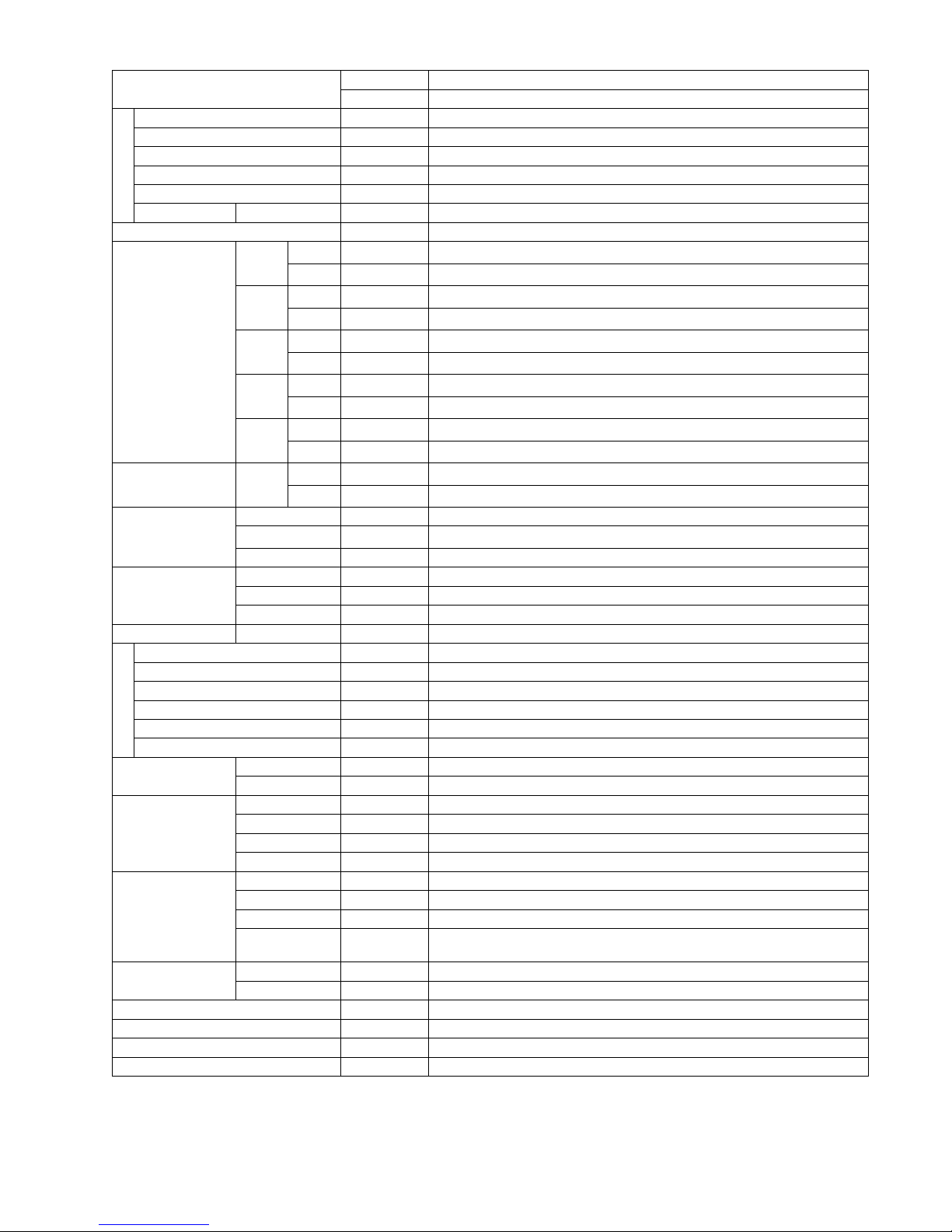
Outdoor Fan
Type Propeller Fan
Material PP
Motor Type Induction (6-poles)
Input Power W 70
Output Power W 30
Speed Hi rpm 830
Moisture Removal L/h (Pt/h) 2.0 (4.2)
Indoor Airflow
QLo
Cool
m
3
/min (ft3/min)
4.9 (173)
Heat
m
3
/min (ft3/min)
5.3 (187)
Lo
Cool
m
3
/min (ft3/min)
7.2 (254)
Heat
m
3
/min (ft3/min)
9.4 (332)
Me
Cool
m
3
/min (ft3/min)
9.7 (343)
Heat
m
3
/min (ft3/min)
11.0 (389)
Hi
Cool
m
3
/min (ft3/min)
12.5 (440)
Heat
m
3
/min (ft3/min)
12.8 (450)
SHi
Cool
m
3
/min (ft3/min)
13.1 (463)
Heat
m
3
/min (ft3/min)
13.3 (470)
Outdoor Airflow Hi
Cool
m
3
/min (ft3/min)
31.0 (1090)
Heat
m
3
/min (ft3/min)
31.0 (1090)
Refrigeration Cycle
Control Device Check Valve & Capillary Tube
Refrigerant Oil
cm
3
RB68A or Freol Alpha 68M (320)
Refrigerant Type g (oz) R410A, 970 (34.2)
Dimension Height (I/D / O/D) mm (inch) 290 (11-7/16) / 540 (21-9/32)
Width (I/D / O/D) mm (inch) 870 (34-9/32) / 780 (30-23/32)
Depth (I/D / O/D) mm (inch) 204 (8-1/16) / 289 (11-13/32)
Weight Net (I/D / O/D) kg (lb) 9 (20) / 34 (75)
Piping
Pipe Diameter (Liquid / Gas) mm (inch) 6.35 (1/4) / 9.52 (3/8)
Standard Length m (ft) 5 (16.4)
Length Range (min - max) m (ft) 3 (9.8) ~ 15 (49.2)
I/D & O/D Height Different m (ft) 15.0 (49.2)
Additional Gas Amount g/m (oz/ft) 20 (0.2)
Length for Additional Gas m (ft) 7.5 (24.6)
Drain Hose
Inner Diameter mm 16
Length mm 650
Indoor Heat
Exchanger
Fin Material Aluminium (Pre Coat)
Fin Type Slit Fin
Row x Stage x FPI 2 x 15 x 21
Size (W x H x L) mm 610 x 315 x 25.4
Outdoor Heat
Exchanger
Fin Material Aluminium
Fin Type Corrugated Fin
Row x Stage x FPI 2 x 24 x 17
Size (W x H x L) mm
36.4 x 504 x 713
684
Air Filter
Material Polypropelene
Type One-touch
Power Supply Outdoor Power Supply
Power Supply Cord A Nil
Thermostat Electronic Control
Protection Device Electronic Control
MODEL INDOOR CS-E12LKEW, CS-XE12LKEW
OUTDOOR CU-E12LKE-3
 Loading...