

Panasonic cu-3e19, cu-4e24rbu service manual
Order No: PAPAMY1505100CE
Air Conditioner
Outdoor Unit
CU-3E19RBU
CU-4E24RBU
Destination
U.S.A.
Canada
Please file and use this manual together with the service manual for Model No. CS-E9RKUAW CS-E12RKUAW CS-E18RKUAW,
CS-E24RKUAW, CS-ME7RKUA, CS-E12RB4UW, CS-E18RB4UW, CS-ME5RKUA, Order No. PAPAMY1501049CE,
PAPAMY1503094CE, PAPAMY1503095CE, PAPAMY1505112CE.
This service information is designed for experienced repair technicians only and is not designed for use by the general public.
It does not contain warnings or cautions to advise non-technical individuals of potential dangers in attempting to service a product.
Products powered by electricity should be serviced or repaired only by experienced professional technicians. Any attempt to
service or repair the product or products dealt with in this service information by anyone else could result in serious injury or death.
WARNING
IMPORTANT SAFETYNOTICE
There are special components used in this equipment which are important for safety. These parts are marked by in the Schematic
Diagrams, Circuit Board Diagrams, Exploded Views and Replacement Parts List. It is essential that these critical parts should be replaced
with manufacturer’s specified parts to prevent shock, fire or other hazards. Do not modify the original design without permission of
manufacturer.
In order to avoid frostbite, be assured of no refrigerant leakage during the installation or repairing of refrigerant circuit.
PRECAUTION OF LOW TEMPERATURE
© Panasonic Corporation 2015
!

TABLE OF CONTENTS
PAGE PAGE
1. Safety Precautions ............................................. 3
2. Specifications ..................................................... 5
2.1 CU-3E19RBU ............................................... 5
2.2 CU-4E24RBU ............................................... 7
3. Dimensions ....................................................... 16
3.1 CU-3E19RBU ............................................. 16
3.2 CU-4E24RBU ............................................. 16
4. Refrigeration Cycle Diagram ........................... 17
4.1 CU-3E19RBU ............................................. 17
4.2 CU-4E24RBU ............................................. 18
5. Block Diagram .................................................. 19
5.1 CU-3E19RBU ............................................. 19
5.2 CU-4E24RBU ............................................. 20
6. Wiring Connection Diagram ............................ 21
6.1 CU-3E19RBU ............................................. 21
6.2 CU-4E24RBU ............................................. 22
7. Electronic Circuit Diagram .............................. 23
7.1 CU-3E19RBU ............................................. 23
7.2 CU-4E24RBU ............................................. 24
8. Printed Circuit Board ....................................... 25
8.1 Main Printed Circuit Board ......................... 25
8.2 Noise Filter Printed Circuit Board ............... 27
8.3 Display Printed Circuit Board ..................... 28
9. Installation Information .................................... 29
9.1 CU-3E19RBU ............................................. 29
9.2 CU-4E24RBU ............................................. 30
13.12 IPM (power transistor) Protection
Control ........................................................47
13.13 Compressor Protection Control
(Gas leak detection control 1) ....................47
13.14 Compressor Protection Control
(Gas leak detection control 2) ....................47
13.15 Valve close detection control ......................48
13.16 Compressor discharge high pressure
protection control ........................................48
14. Servicing Mode .................................................49
14.1 CU-3E19RBU .............................................49
14.2 CU-4E24RBU .............................................51
15. Troubleshooting Guide ....................................53
15.1 Self Diagnosis Function ..............................53
15.2 Self-diagnosis Method ................................55
16. Disassembly and Assembly Instructions ......79
16.1 Outdoor Unit Removal Procedure
(CU-3E19RBU) ...........................................79
16.2 Outdoor Unit Removal Procedure
(CU-4E24RBU) ...........................................81
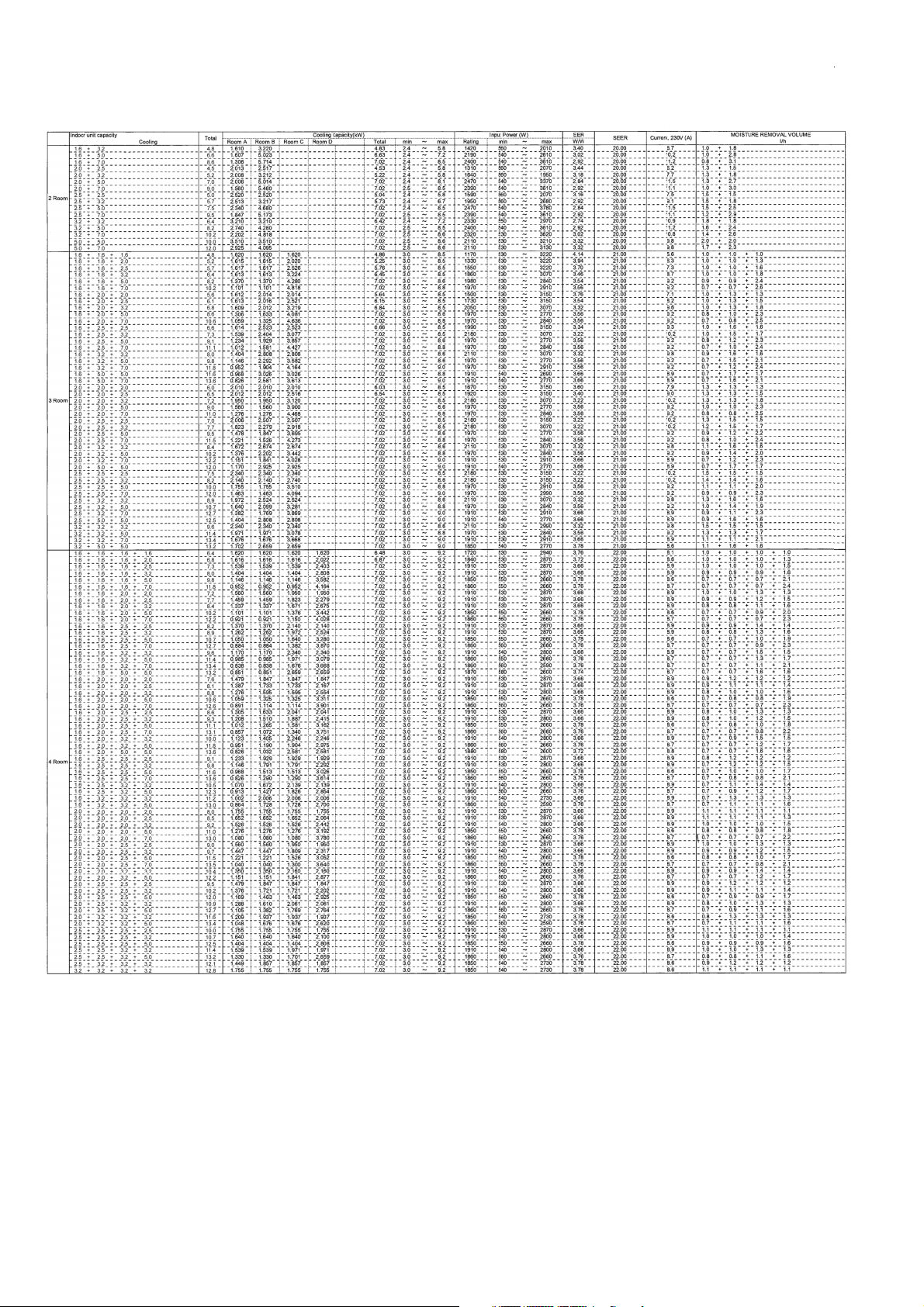
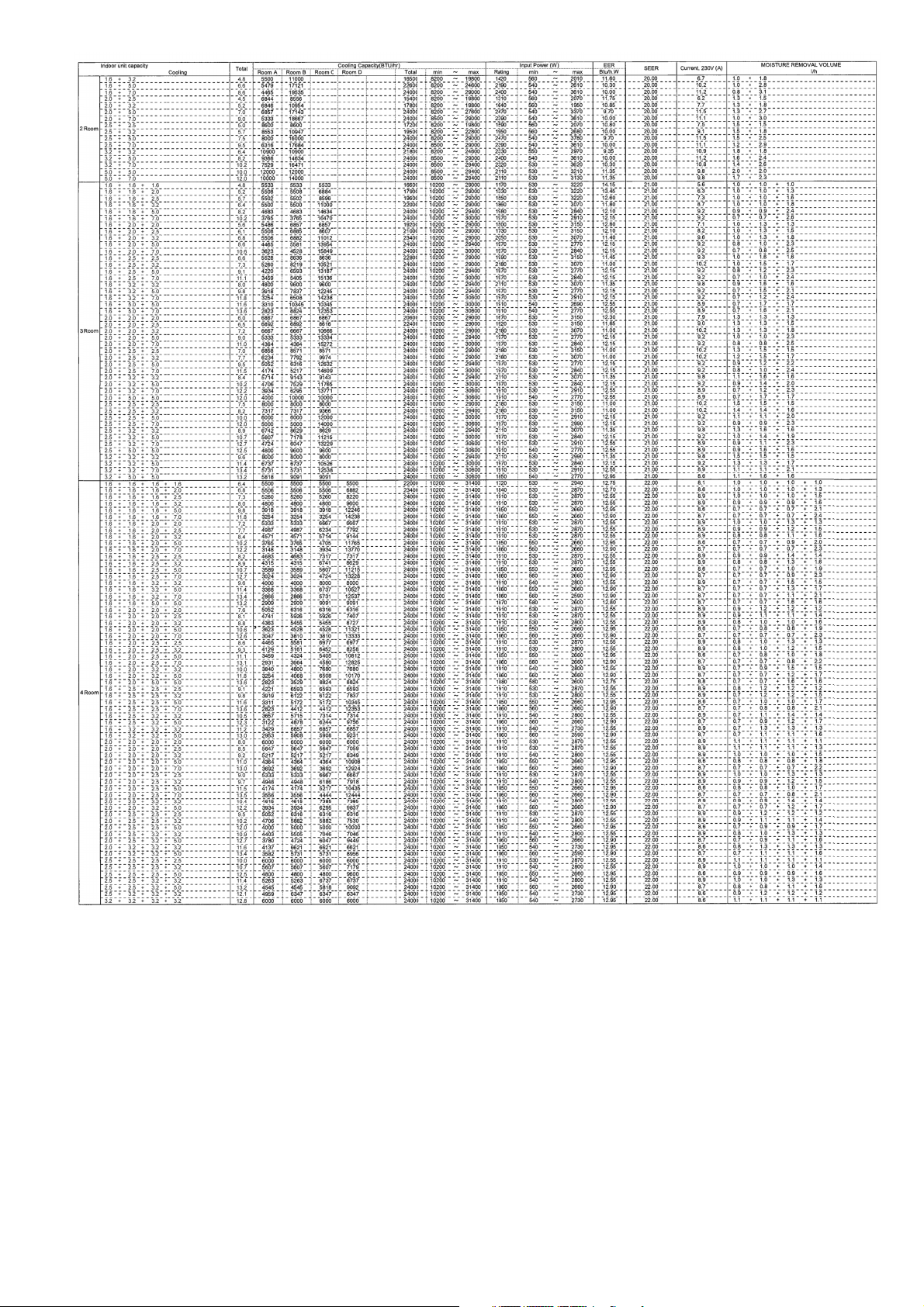
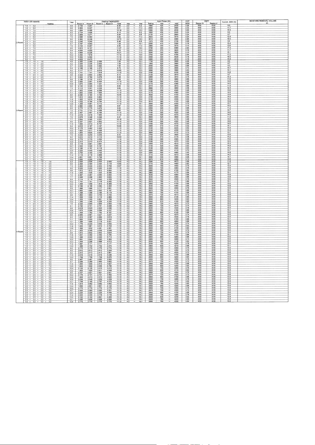
17. Technical Data ..................................................84
17.1 CU-3E19RBU .............................................84
17.2 CU-4E24RBU .......................................... 108
18. Exploded View and Replacement Parts
List .................................................................. 191
18.1 CU-3E19RBU .......................................... 191
18.2 CU-4E24RBU .......................................... 194
10. Installation Instruction ..................................... 31
10.1 CU-3E19RBU ............................................. 31
10.2 CU-4E24RBU ............................................. 36
11. Operation Control ............................................. 41
11.1 Cooling Operation ....................................... 41
11.2 Heating Operation ...................................... 42
12. Simultaneous Operation Control .................... 43
13. Protection Control ............................................ 44
13.1 Freeze Prevention control (Cool) ............... 44
13.2 Dew Prevention control (Cool) ................... 44
13.3 Electronic Parts Temperature Rise
Protection 1 (Cool) ...................................... 44
13.4 Electronic Parts Temperature Rise
Protection 2 (Cool) ...................................... 44
13.5 Cooling overload control (Cool) .................. 45
13.6 Heating overload control (Heat) ................. 45
13.7 Extreme Low Temperature Compressor
low pressure protection control (Heat) ....... 46
13.8 Deice Control .............................................. 46
13.9 Time Delay Safety Control
(Restart Control) ......................................... 46
13.10 30 seconds Force Operation ...................... 46
13.11 Total Current Control .................................. 46
2

1. Safety Precautions
Read the following “SAFETY PRECAUTIONS” carefully before perform any servicing.
Electrical work must be installed or serviced by a licensed electrician. Be sure to use the correct rating of the
power plug and main circuit for the model installed.
The caution items stated here must be followed because these important contents are related to safety. The
meaning of each indication used is as below. Incorrect installation or servicing due to ignoring of the instruction
will cause harm or damage, and the seriousness is classified by the following indications.
WARNING
CAUTION
The items to be followed are classified by the symbols:
This symbol denotes item that is PROHIBITED from doing.
Carry out test run to confirm that no abnormality occurs after the servicing. Then, explain to user the operation,
care and maintenance as stated in instructions. Please remind the customer to keep the operating instructions for
future reference.
1. Do not modify the machine, part, material during repairing service.
This indication shows the possibility of causing death or serious injury.
This indication shows the possibility of causing injury or damage to properties.
WARNING
2. If wiring unit is supplied as repairing part, do not repair or connect the wire even only partial wire break. Exchange the whole wiring unit.
3. Do not wrench the fasten terminal. Pull it out or insert it straightly.
4. Engage dealer or specialist for installation and servicing. If installation or servicing done by the user is defective, it will cause water leakage,
electrical shock or fire.
5. Install according to this installation instructions strictly. If installation is defective, it will cause water leakage, electric shock or fire.
6. Use the attached accessories parts and specified parts for installation and servicing. Otherwise, it will cause the set to fall, water leakage,
fire or electrical shock.
7. Install at a strong and firm location which is able to withstand the set’s weight. If the strength is not enough or installation is not properly done,
the set will drop and cause injury.
8. For electrical work, follow the local national wiring standard, regulation and the installation instruction. An independent circuit and single outlet
must be used. If electrical circuit capacity is not enough or defect found in electrical work, it will cause electrical shock or fire.
9. This equipment is strongly recommended to install with Earth Leakage Circuit Breaker (ELCB) or Residual Current Device (RCD).
Otherwise, it may cause electrical shock and fire in case equipment breakdown or insulation breakdown.
10. Do not use joint cable for indoor/outdoor connection cable. Use the specified indoor/outdoor connection cable, refer to Installation
Instruction CONNECT THE CABLE TO THE INDOOR UNIT and connect tightly for indoor/outdoor connection. Clamp the cable so that no
external force will be acted on the terminal. If connecting or fixing is not perfect, it will cause heat up or fire at the connection.
11. Wire routing must be properly arranged so that control board cover is fixed properly. If control board cover is not fixed perfectly, it will cause
heat-up or fire at the connection point of terminal, fire or electrical shock.
12. When install or relocate air conditioner, do not let any substance other than the specified refrigerant, eg. air etc. mix into refrigeration cycle
(piping). (Mixing of air etc. will cause abnormal high pressure in refrigeration cycle and result in explosion, injury etc.).
13. Do not install outdoor unit near handrail of veranda. When installing air-conditioner unit at veranda of high rise building, child may climb up to
outdoor unit and cross over the handrail and causing accident.
14. This equipment must be properly earthed. Earth line must not be connected to gas pipe, water pipe, earth of lightning rod and
telephone. Otherwise, it may cause electric shock in case equipment breakdown or insulation breakdown.
15. Keep away from small children, the thin film may cling to nose and mouth and prevent breathing.
16. Do not use unspecified cord, modified cord, joint cord or extension cord for power supply cord. Do not share the single outlet
with other electrical appliances. Poor contact, poor insulation or over current will cause electrical shock or fire.
17. Tighten the flare nut with torque wrench according to specified method. If the flare nut is over-tightened, after a long period, the
flare may break and cause refrigerant gas leakage.
3
18. For R410A models, when connecting the piping, do not use any existing (R22) pipes and flare nuts. Using such same may
cause abnormally high pressure in the refrigeration cycle (piping), and possibly result in explosion and injury. Use only R410A
materials.
Thickness of copper pipes used with R410A must be more than 1/32" (0.8mm). Never use copper pipes thinner than 1/32" (0.8mm).
It is desirable that the amount of residual oil is less than 0.0014 oz/32.8 ft (40 mg/10m).
19. During installation, install the refrigerant piping properly before run the compressor. (Operation of compressor without fixing refrigeration
piping and valves at opened condition will cause suck-in of air, abnormal high pressure in refrigeration cycle and result in explosion, injury
etc.).
20. During pump down operation, stop the compressor before remove the refrigeration piping. (Removal of refrigeration piping while
compressor is operating and valves are opened condition will cause suck-in of air, abnormal high pressure in refrigeration cycle and result
in explosion, injury etc.).
21. After completion of installation or service, confirm there is no leakage or refrigerant gas. It may generate toxic gas when the refrigerant
contacts with fire.
22. Ventilate if there is refrigerant gas leakage during operation. It may cause toxic gas when refrigerant contacts with fire.
23. Do not insert your fingers or other objects into the unit, high speed rotating fan may cause injury.
24. Must not use other parts except original parts described in catalog and manual.
25. Using of refrigerant other than the specified type may cause product damage, burst and injury etc.
WARNING
CAUTION
1. Do not install the unit at place where leakage of flammable gas may occur. In case gas leaks and accumulates at surrounding of the
unit, it may cause fire.
2. Carry out drainage piping as mentioned in installation instructions. If drainage is not perfect, water may enter the room and damage
the furniture.
3. Tighten the flare nut with torque wrench according to specified method. If the flare nut is over-tightened, after a long period, the flare
may break and cause refrigerant gas leakage.
4. Do not touch outdoor unit air inlet and aluminium fin. It may cause injury.
5. Select an installation location which is easy for maintenance.
6. Pb free solder has a higher melting point than standard solder; typically the melting point is 50°F – 70°F (30°C – 40°C) higher. Please use
a high temperature solder iron. In case of the soldering iron with temperature control, please set it to 700 ± 20°F (370 ± 10°C). Pb free solder
will tend to splash when heated too high (about 1100°F / 600°C).
7. Power supply connection to the room air conditioner.
Power supply cord shall be UL listed or CSA approved 3 conductor with minimum AWG12 wires.
Power supply point should be in an easily accessible place for power disconnection in case of emergency.
In some countries, permanent connection of this air conditioner to the power supply is prohibited.
Fix power supply connection to a circuit breaker for permanent connection.
Use NRTL approved fuse or circuit breaker (rating refers to name plate) for permanent connection.
8. Do not release refrigerant during piping work for installation, servicing, reinstallation and during repairing a refrigerant parts.
Take care of the liquid refrigerant, it may cause frostbite.
9. Installation or servicing work: It may need two people to carry out the installation or servicing work.
10. Do not install this appliance in a laundry room or other location where water may drip from the ceiling, etc.
11. Do not sit or step on the unit, you may fall down accidentally.
12. Do not touch the sharp aluminum fins or edges of metal parts.
If you are required to handle sharp parts during installation or servicing, please wear hand glove.
Sharp parts may cause injury.
4
2. Specifications
3
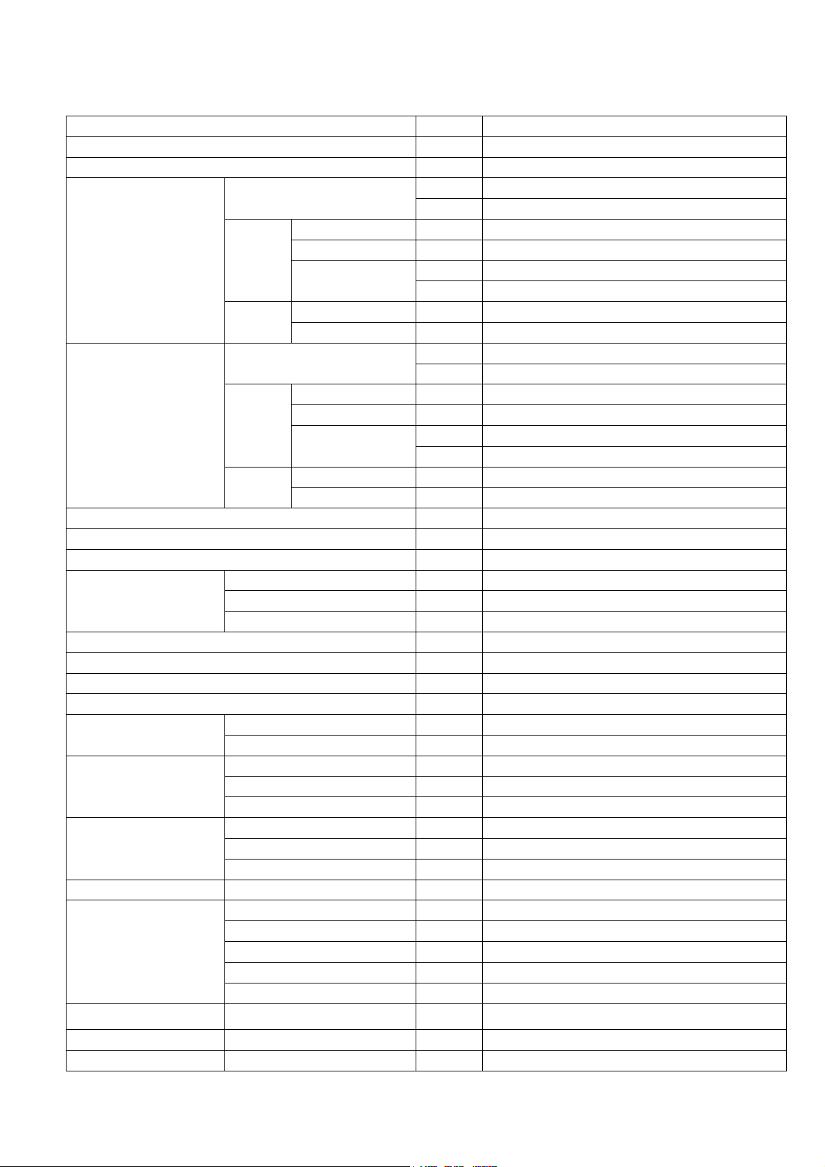
2.1 CU-3E19RBU
Item Unit OUTDOOR UNIT
Indoor Unit Combination 1.6kW + 2.0kW + 2.0kW
Power Source 1 Phase, 208-230V, 60Hz (Power supply from outdoor unit)
Capacity
Running Current A 7.4 - 6.7
Cooling Operation
Heating Operation
Maximum Current A 15.0
Starting Current A 10.1
Circuit Breaker Capacity A 30
Dimension
Net Weight kg (lb) 72 (159)
Connection Cable 3 + 1 (Earth) min AWG16
Pipe Length Range (1 room) m (ft) 3 ~ 25 (9.8 ~ 82.0)
Maximum Pipe Length (Total Room) m (ft) 50 (164.0)
Refrigerant Pipe Diameter
Compressor
Air Circulation
Fan Speed High (Cooling / Heating) RPM 580 / 650
Heat Exchanger
Air Volume High (Cooling / Heating)
Refrigerant Control Device Expansion Valve
Refrigerant Oil FV50S
Electrical
Data
Noise
Capacity
Electrical
Data
Noise
Height mm (inch) 795 (31-5/16)
Width mm (inch) 875 + 95 (34-15/32) + (3-3/4)
Depth mm (inch) 320 (12-5/8)
Liquid Side mm (inch) 6.35 (1/4)
Gas Side mm (inch) 9.52 (3/8)
Type Hermetic Motor / Rotary
Motor Type Brushless (4-poles)
Rated Output W 1.30k
Type Propeller Fan
Motor Type DC Motor (8-poles)
Rated Output W 60
Type Plate fin configuration forced draft type
Tube Material Copper
Fin Material Aluminum (Blue Coated)
Row / Stage 2 / 36
FPI 19
Power Input kW 1.51 (0.36 ~ 2.42)
EER
Sound Pressure Level dB-A (H/L) 50 / -
Sound Power Level dB (H/L) 66 / -
Running Current A 10.1 - 9.1
Power Input kW 2.06 (0.32 ~ 2.30)
COP
Sound Pressure Level dB-A (H/L) 52 / -
Sound Power Level dB (H/L) 68 / -
kW 5.58 (1.8 ~ 7.3)
BTU/h 19000 (6100 ~ 24800)
W/W 3.68 (5.00 ~ 3.02)
BTU/hW 12.55 (16.95 ~ 10.25)
kW 7.65 (1.6 ~ 8.3)
BTU/h 26000 (5500 ~ 28400)
W/W 3.70 (5.00 ~ 3.61)
BTU/hW 12.60 (17.20 ~ 12.35)
/min
m
(ft
3
/min)
41.0 (1447) / 46.3 (1634)
5
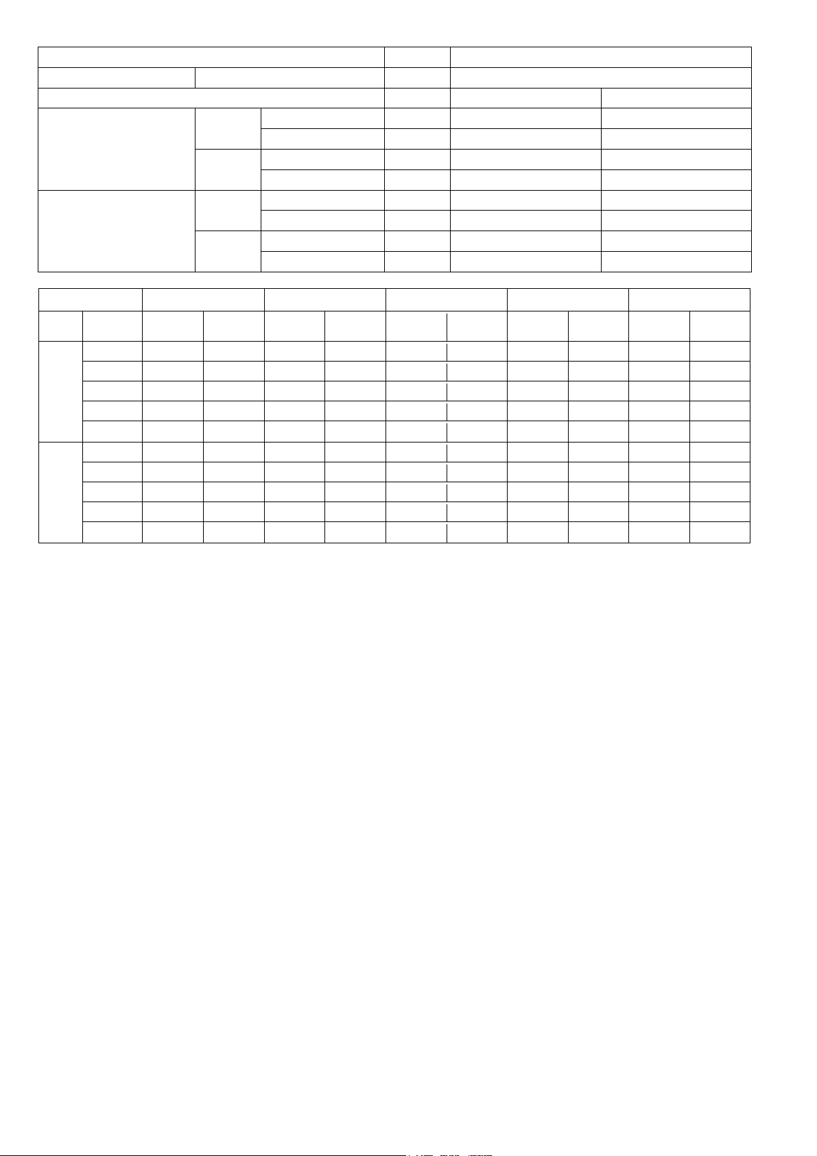
Item Unit OUTDOOR UNIT
Refrigerant (R410A) g (oz) 2.64k (93.2)
Dry Bulb Wet Bulb
Cooling
Indoor Operation Range
Heating
Cooling
Outdoor Operation Range
Heating
Maximum °C (°F) 32 (89.6) 23 (73.4)
Minimum °C (°F) 16 (60.8) 11 (51.8)
Maximum °C (°F) 30 (86.0) —
Minimum °C (°F) 16 (60.8) —
Maximum °C (°F) 46 (114.8) 26 (78.8)
Minimum °C (°F) -10 (14.0) —
Maximum °C (°F) 24 (75.2) 18 (64.4)
Minimum °C (°F) -15 (5.0) -16 (3.2)
Multi Indoor RPM CS-ME5RKUA CS-ME7RKUA CS-E9RKUAW CS-E12RKUAW CS-E18RKUAW
Mode Fan Tap rpm
SHi 1080 11.71 1110 12.10 1140 12.21 1280 13.35 1370 18.96
Hi 990 10.70 1020 11.10 1050 11.20 1160 12.00 1330 18.40
COOL
HEAT
Me 820 8.80 840 9.08 850 8.96 940 9.54 1160 16.03
Lo 660 7.00 660 7.06 660 6.83 720 7.08 990 13.65
Lo- 570 6.00 570 6.06 570 5.83 580 5.51 900 12.40
SSHi 1210 12.70 1240 13.11 1270 13.21 1370 14.29 1460 20.46
SHi 1120 11.70 1150 12.10 1180 12.20 1300 13.50 1370 19.20
Me 950 9.79 960 9.97 980 9.96 1140 11.71 1210 16.97
Lo 780 7.89 780 7.96 780 7.72 980 9.92 1060 14.87
Lo- 690 6.88 690 6.95 690 6.71 890 8.91 960 13.48
Airflow
(m3/min)
rpm
Airflow
(m3/min)
rpm
Airflow
(m3/min)
rpm
Airflow
(m3/min)
rpm
Airflow
(m3/min)
Note
Specifications are subject to change without notice for further improvement.
6
2.2 CU-4E24RBU
3
Item Unit OUTDOOR UNIT
Indoor Unit Combination 1.6kW + 1.6kW + 2.0kW + 2.0kW
Power Source 1 Phase, 208-230V, 60Hz (Power supply from outdoor unit)
Capacity
Running Current A 9.9 - 8.9
Cooling Operation
Heating Operation
Maximum Current A 21.1
Starting Current A 15.3
Circuit Breaker Capacity A 45
Dimension
Net Weight kg (lb) 83 (183)
Connection Cable 3 + 1 (Earth) min AWG16
Pipe Length Range (1 room) m (ft) 3 ~ 25 (9.8 ~ 82.0)
Maximum Pipe Length (Total Room) m (ft) 70 (229.6)
Refrigerant Pipe Diameter
Compressor
Air Circulation
Fan Speed High (Cooling / Heating) RPM 600 / 700
Heat Exchanger
Air Volume High (Cooling / Heating)
Refrigerant Control Device Expansion Valve
Refrigerant Oil FV50S
Refrigerant (R410A) g (oz) 3.40k (120)
Electrical
Data
Noise
Capacity
Electrical
Data
Noise
Height mm (inch) 999 (39-11/32)
Width mm (inch) 940 (37-1/32)
Depth mm (inch) 340 (13-13/32)
Liquid Side mm (inch) 6.35 (1/4)
Gas Side mm (inch) 9.52 (3/8), (E24: 12.70 (1/2))
Type Hermetic Motor / Rotary
Motor Type Brushless (4-poles)
Rated Output W 1.30k
Type Propeller Fan
Motor Type DC Motor (8-poles)
Rated Output W 90
Type Plate fin configuration forced draft type
Tube Material Copper
Fin Material Aluminum (Blue Coated)
Row / Stage 2 / 46
FPI 19
Power Input kW 1.91 (0.53 ~ 2.87)
EER
Sound Pressure Level dB-A (H/L) 55 / -
Sound Power Level dB (H/L) 71 / -
Running Current A 15.3 - 13.9
Power Input kW 3.03 (0.70 ~ 4.38)
COP
Sound Pressure Level dB-A (H/L) 55 / -
Sound Power Level dB (H/L) 71 / -
kW 7.02 (3.0 ~ 9.2)
BTU/h 24000 (10200 ~ 31400)
W/W 3.66 (5.66 ~ 3.21)
BTU/hW 12.55 (19.25 ~ 10.95)
kW 11.1 (4.2 ~ 14.2)
BTU/h 37800 (14300 ~ 48500)
W/W 3.66 (6.00 ~ 3.24)
BTU/hW 12.45 (20.45 ~ 11.05)
/min
m
(ft
3
/min)
55.6 (1963) / 66.0 (2330)
7
Item Unit OUTDOOR UNIT
Dry Bulb Wet Bulb
Cooling
Indoor Operation Range
Heating
Cooling
Outdoor Operation Range
Heating
Maximum °C (°F) 32 (89.6) 23 (73.4)
Minimum °C (°F) 16 (60.8) 11 (51.8)
Maximum °C (°F) 30 (86.0) —
Minimum °C (°F) 16 (60.8) —
Maximum °C (°F) 46 (114.8) 26 (78.8)
Minimum °C (°F) -10 (14.0) —
Maximum °C (°F) 24 (75.2) 18 (64.4)
Minimum °C (°F) -15 (5.0) -16 (3.2)
Multi Indoor
RPM
Mode
COOL
SSHi 1210 12.70 1240 13.11 1270 13.21 1370 14.29 1460 20.46 1500 20.35
HEAT
Fan
Tap
SHi 1080 11.71 1110 12.10 1140 12.21 1280 13.35 1370 18.96 1460 19.94
Hi 990 10.70 1020 11.10 1050 11.20 1160 12.00 1330 18.40 1350 18.40
Me 820 8.80 840 9.08 850 8.96 940 9.54 1160 16.03 1180 16.03
Lo 660 7.00 660 7.06 660 6.83 720 7.08 990 13.65 1020 13.79
Lo- 570 6.00 570 6.06 570 5.83 580 5.51 900 12.40 930 12.54
SHi 1120 11.70 1150 12.10 1180 12.20 1300 13.50 1370 19.20 1460 19.80
Me 950 9.79 960 9.97 980 9.96 1140 11.71 1210 16.97 1310 17.70
Lo 780 7.89 780 7.96 780 7.72 980 9.92 1060 14.87 1160 15.61
Lo- 690 6.88 690 6.95 690 6.71 890 8.91 960 13.48 1050 14.07
CS-ME5RKUA CS-ME7RKUA CS-E9RKUAW CS-E12RKUAW CS-E18RKUAW CS-E24RKUAW
rpm
Airflow
(m3/min)
rpm
Airflow
(m3/min)
rpm
Airflow
(m3/min)
rpm
Airflow
(m3/min)
rpm
Airflow
(m3/min)
rpm
Note
Specifications are subject to change without notice for further improvement.
Airflow
(m3/min)
8

Multi Split Combination Possibility:
o A single outdoor unit enables air conditioning of up to three separate rooms for CU-3E19RBU.
o A single outdoor unit enables air conditioning of up to four separate rooms for CU-4E24RBU.
20 (0.2)
OUTDOOR UNIT
D
CU-3E19RBU
A B C
---
From 4.5kW
to 9.0kW
25 (82.0)
15 (49.2)
50 (164.0)
30 (98.4)
20 (0.2)
Note: “ ” : Available
CONNECTABLE INDOOR UNIT
Ty pe
1.6kW CS-ME5RKUA
2.0kW CS-ME7RKUA
2.5kW CS-E9RKUAW
Wall
connectable indoor units
Pipe
length
Remarks for CU-4E24RBU
1. At least two indoor units must be connected.
2. The total nominal cooling capacity of indoor units that will be connected to outdoor unit must be
within connectable capacity range of indoor unit. (as shown in the table above)
Example: The indoor units’ combination below is possible to connect to CU-4E24RBU.
(Total nominal capacity of indoor units is between 4.5kW to 13.6kW)
1) Two CS-E9RKUAW only (Total nominal cooling capacity is 5.0kW)
2) Three CS-E12RKUAW. (Total nominal cooling capacity is 9.6kW)
CS-E12RKUAW,
3.2kW
CS-E12RB4UW
CS-E18RKUAW,
5.0kW
CS-E18RB4UW
7.0kW CS-E24RKUAW
Capacity range of
1-room maximum
pipe length (m (ft))
Allowable elevation
Total allowable pipe
length (m (ft))
Total pipe length for
maximum chargeless
length (m (ft))
Additional gas
amount over chargeless
length (g/m (oz/ft))
ROOM
(m (ft))
CU-4E24RBU
A B C
From 4.5kW
to 13.6kW
25 (82.0)
15 (49.2)
70 (229.6)
45 (147.6)
9
I
n
O
C
:
U
B
R
E
C
A
A
C
door Unit :
S-E18RB4U
utdoor Unit
S-ME5RK
W
CU-3E19R
A, CS-ME7
U
KUA, CS-
9RKUAW,
S-E12RKU
W, CS-E18RKUAW, CS-E12RB4U W,
10
11
I
n
O
C
:
U
R
B
R
E
C
C
door Unit :
S-E12RB4U
utdoor Unit
S-ME5RK
W, CS-E18
CU-4E24R
A, CS-ME7
B4UW
U
KUA, CS-
9RKUAW,
S-E12RKUAW, CS-E18RKUAW, CS-E24RKUAW,
12
13
14

15

3. Dimensions
3.1 CU-3E19RBU
Space necessary for
installation
3-15/16 (10 cm)
3-15/16 (10 cm)
39-3/8 (100 cm)
Anchor Bolt Pitch
14-3/16 (360.5) x 24-9/64 (613)
<Side View> <Side View>
Unit: inch (mm)
1-5/64
(27.5)
<Top View>
(5-5/32
(131))
<Front View>
24-9/64 (613)
34-15/32 (875)
5-5/32
(131)
15/16
(23.8)
3-3/4
2-3/64
(52)
(95)
3-17/64
1-21/32
(42)
(25)
63/64
(83)
(38)
1-1/2
5-7/32
(132.5)
(41)
14-3/16 (360.5)
1-39/64
2-21/64
(59)
(85.7 x 3 = 257.1)
3-3/8 X 1/8 = 10-1/8
(17)
43/64
(81))
(91.2)
3-19/32
(3-3/16
(167))
(6-37/64
(85.7 x 3 = 257.1)
3-3/8 X 1/8 = 10-1/8
(210))
(8-17/64
12-5/8 (320)
31-5/16 (795)
3.2 CU-4E24RBU
Space necessary for
installation
3-15/16 (10 cm)
3-15/16 (10 cm)
39-3/8 (100 cm)
Anchor Bolt Pitch
24-13/32 (620) x 14-31/32 (380.5)
<Top View>
<Front View> <Side View><Side View>
39-11/32 (999)
24-13/32 (620)
37-1/32 (940)
6-11/16 (170)
1-7/16 (36.2)
14-31/32 (380.5)
1-13/32 (36)
13-13/32 (340)
13/64 (5.5)
16-17/32
4-1/8 x 5/32 =
(105 x 4 = 420)
2-21/32
(67.7)
16-17/32
4-1/8 x 5/32 =
(105 x 4 = 420)
5-3/32
(129.5)
Unit: inch (mm)
16
(27)
1-1/16
(74.5)
2-15/16

4. Refrigeration Cycle Diagram
4.1 CU-3E19RBU
INDOOR A OUTDOOR
LIQUID SIDE
3-WAYVALVE
INTAKE
TEMP.
SENSOR
HEAT
EXCHANGER
(EVAPORATOR)
INTAKE
TEMP.
SENSOR
PIPE
TEMP.
SENSOR
PIPE
TEMP.
SENSOR
LIQUID SIDE
3-WAYVALVE
LIQUID SIDE
3-WAYVALVE
GAS SIDE
3-WAY VALVE
PIPE
TEMP.
SENSOR
PIPE
TEMP.
SENSOR
PIPE
TEMP.
SENSOR
STRAINER
STRAINER
STRAINER
EXPANSION
VALV E A
EXPANSION
VALV E B
EXPANSION
VALV E C
3-WAY
VALVE
STRAINER
PIPE TEMP.
SENSOR (DEF)
INTAKE
TEMP.
SENSOR
CONDENSOR
TEMP.
SENSOR
HEAT
EXCHANGER
(EVAPORATOR)
INTAKE
TEMP.
SENSOR
HEAT
EXCHANGER
(EVAPORATOR)
INDOOR B
INDOOR C
PIPE
TEMP.
SENSOR
GAS SIDE
3-WAY
VALV E
GAS SIDE
3-WAY
VALV E
PIPE
TEMP.
SENSOR
PIPE
TEMP.
SENSOR
PIPE
TEMP.
SENSOR
3-WAY
VALV E
EXCHANGER
(CONDENSOR)
COMPRESSOR
TEMP.
SENSOR
PRESSURE
SWITCH
DISCHARGE
MUFFLER
COMPRESSOR
HEAT
4-WAY
VALV E
ACCUMULATOR
17
COOLING
HEATING
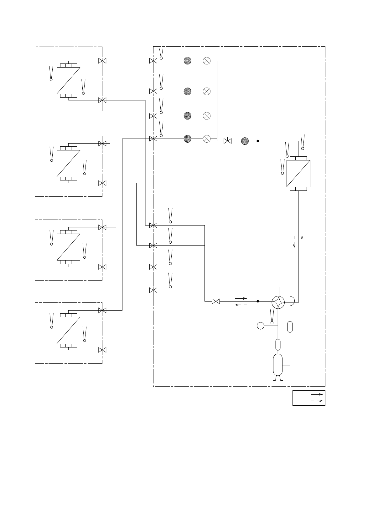
4.2 CU-4E24RBU
INDOOR A OUTDOOR
INTAKE
TEMP.
SENSOR
HEAT
EXCHANGER
(EVAPORATOR)
INTAKE
TEMP.
SENSOR
PIPE
TEMP.
SENSOR
PIPE
TEMP.
SENSOR
LIQUID SIDE
3-WAY VALVE
LIQUID SIDE
3-WAY VALVE
LIQUID SIDE
3-WAY VALVE
LIQUID SIDE
GAS SIDE
3-WAY VALVE
3-WAY VALVE
PIPE
TEMP.
SENSOR
PIPE
TEMP.
SENSOR
PIPE
TEMP.
SENSOR
PIPE
TEMP.
SENSOR
STRAINER
STRAINER
STRAINER
STRAINER
EXPANSION
VALV E A
EXPANSION
VALV E B
EXPANSION
VALVE C
EXPANSION
VALVE D
3-WAY
VALVE
STRAINER
PIPE TEMP.
SENSOR (DEF)
INTAKE
TEMP.
SENSOR
CONDENSOR
TEMP.
SENSOR
HEAT
EXCHANGER
(EVAPORATOR)
INTAKE
TEMP.
SENSOR
HEAT
EXCHANGER
(EVAPORATOR)
INTAKE
TEMP.
SENSOR
HEAT
EXCHANGER
(EVAPORATOR)
INDOOR B
INDOOR C
INDOOR D
PIPE
TEMP.
SENSOR
PIPE
TEMP.
SENSOR
GAS SIDE
3-WAY
VALVE
GAS SIDE
3-WAY
VALVE
GAS SIDE
3-WAY
VALVE
PIPE
TEMP.
SENSOR
PIPE
TEMP.
SENSOR
PIPE
TEMP.
SENSOR
PIPE
TEMP.
SENSOR
3-WAY
VALV E
(CONDENSOR)
COMPRESSOR
TEMP.
SENSOR
PRESSURE
SWITCH
DISCHARGE
MUFFLER
COMPRESSOR
HEAT
EXCHANGER
4-WAY
VALVE
ACCUMULATOR
18
COOLING
HEATING
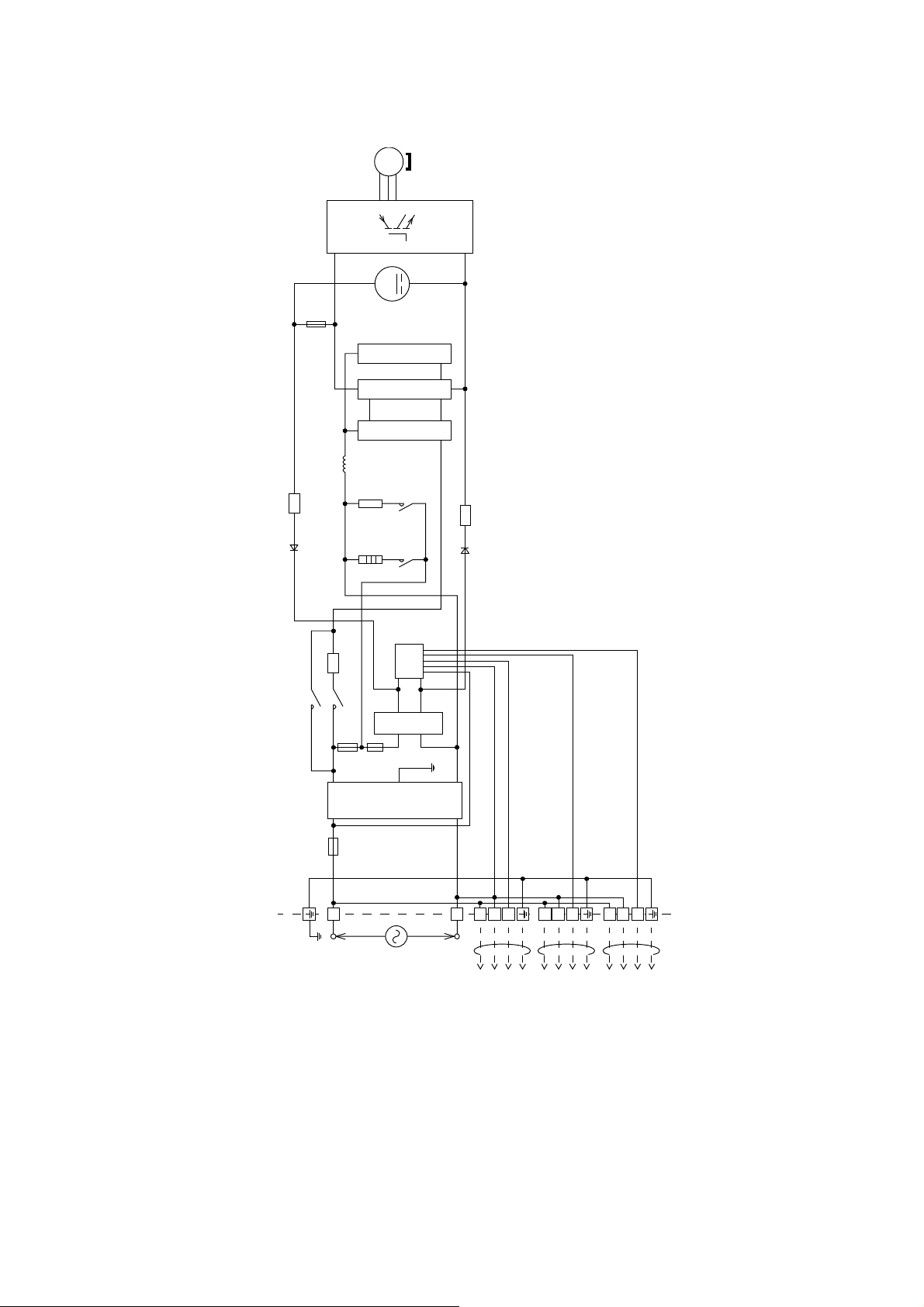
5. Block Diagram
5.1 CU-3E19RBU
3~
MS
M
FUSE 1
PFC CIRCUIT
CAPACITOR CIRCUIT
CIRCUIT
RECTIFICATION
REACTOR
4-WAY
VALV E
NTC
RY-HOT
NTC
HEATER
RY-HT
PTC
RY-AC
RY-PWR
FUSE 2
FUSE 401
(OUTDOOR UNIT)
L1
SC
CIRCUIT
RECTIFICATION
NTC
CIRCUIT
NOISE FILTER
123
L2
123
123
SINGLE PHASE
POWER SUPPLY
TO INDOOR UNIT A
TO INDOOR UNIT B
TO INDOOR UNIT C
19
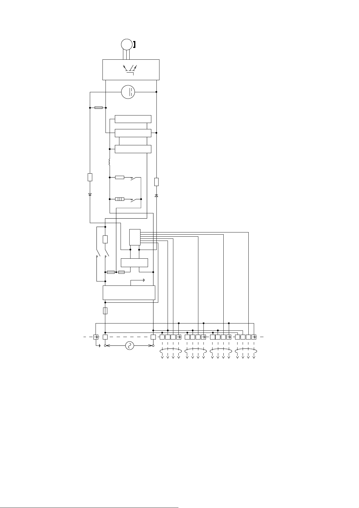
5.2 CU-4E24RBU
NTC
3~
MS
M
FUSE 1
PFC CIRCUIT
CAPACITOR CIRCUIT
CIRCUIT
RECTIFICATION
REACTOR
4-WAY
VALV E
RY-HOT
NTC
HEATER
RY-HT
NTC
SINGLE PHASE
SC
CIRCUIT
RECTIFICATION
CIRCUIT
NOISE FILTER
123
L2
POWER SUPPLY
AC 208/230V
60Hz
123
TO INDOOR UNIT A
TO INDOOR UNIT B
123
TO INDOOR UNIT C
123
TO INDOOR UNIT D
PTC
RY-AC
RY-PWR
FUSE 2
FUSE 401
(OUTDOOR UNIT)
L1
20
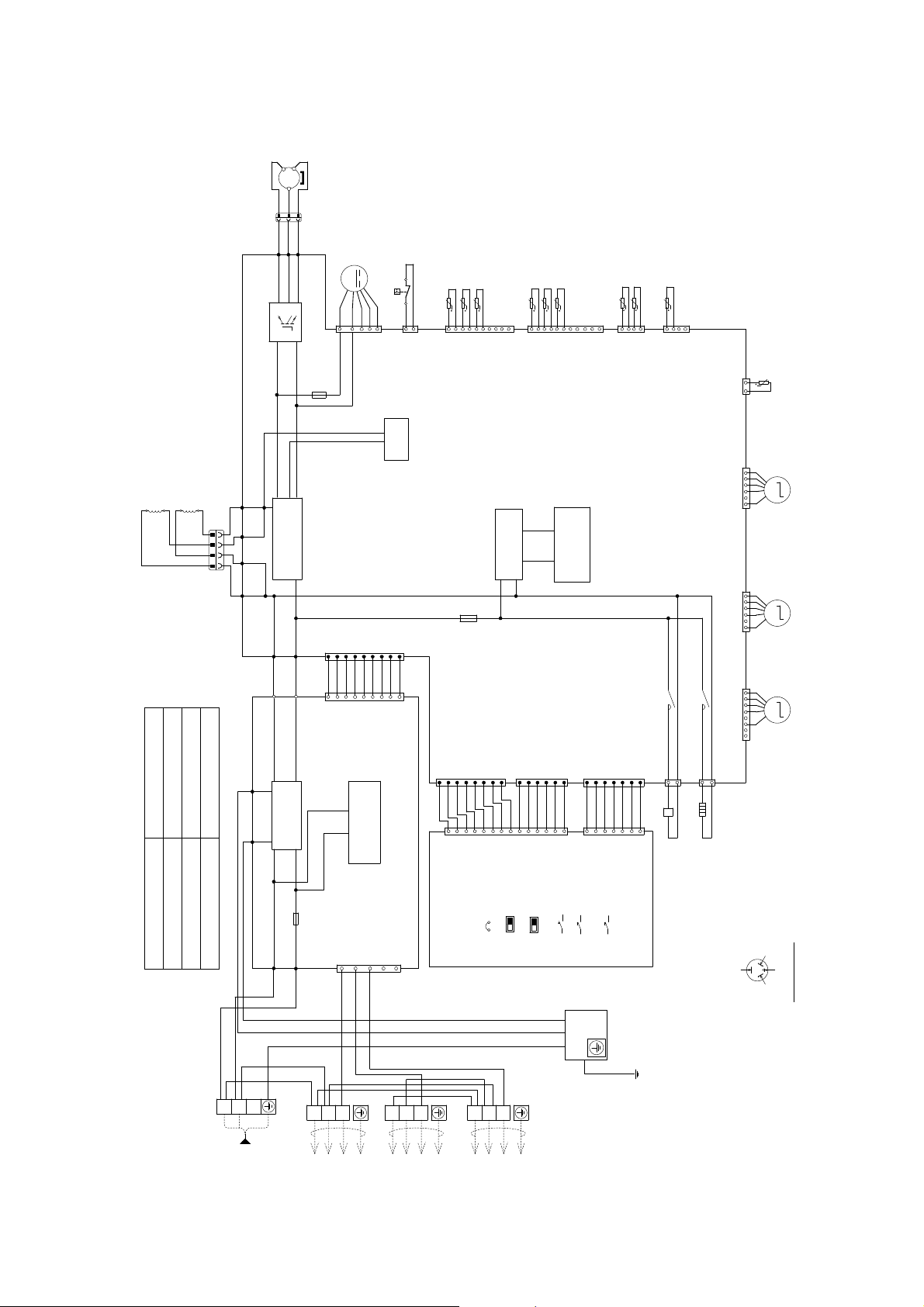
6. Wiring Connection Diagram
Res
s
t
ance
o
C
o
pre
s
sor
W
d
s
6.1 CU-3E19RBU
3~
MS
COMPRESSOR
B
Y
R
33
11
B
Y
R
CONNECTOR
WHITE
V
U
W
)
)
ing
in
m
f
i
)
RED
BLUE
(
(
YELLOW
(
U
V
W
P
N
Q10
L2-O
(BLK)
REACTOR
REACTOR
GRY
BLK
GRY
0.72
5KD184XAB21 (Ω)
U-V
CONNECTION
BLK
CONNECTOR
WHITE
1
1
BLK
BLK
L1-O
(BLK)
CIRCUIT
4
4
GRYGRY
0.73
0.71
G
V-W
U-W
W
BLK
L1
RECTIFICATION
L2-I
(GRY)
L1-I
(GRY)
)
)
WHITE
AC-WHT
(
BLACK
AC-BLK
(
W
BLK
)
WHITE
(
CN-WHT
CN-BLK (BLACK)
FG2
(GREEN)
NOISE FILTER
CIRCUIT
FG1
(GREEN)
G
FUSE 401
ACL1
(BLACK)
ACN1
(WHITE)
Y/G
W
BLK
L2
M
B
R
W
BLK
4
1
CN-FM1
FUSE 1
(T3.15A L250V)
)
1
WWWWWWWWW
1
)
COMMUNICATION
(30A 250V)
1
357
B
Y
R
W
123
FAN MOTOR
Y
R
R
1
7
2
(BLUE)
(WHITE)
CN-PSW1
PFC
CIRCUIT
WHITE
(
CN-DATA
WHITE
99
(
CN-DATA
CIRCUIT
ELECTRONIC CONTROLLER (NOISE FILTER)
(WHITE)
CN-COM
9
BLK
123
LIQUID PIPE TEMP. SENSOR (UNIT A) (THERMISTOR)
HIGH PRESSURE SW.
ttt
1
1
WWWWWWW
1
ELECTRONIC CONTROLLER
(DISPLAY)
BLK
LIQUID PIPE TEMP. SENSOR (UNIT B) (THERMISTOR)
CN-TH3
FUSE 2
JP1
123
GAS PIPE TEMP.SENSOR (UNIT A) (THERMISTOR)
LIQUID PIPE TEMP. SENSOR (UNIT C) (THERMISTOR)
(WHITE)
GAS PIPE TEMP.SENSOR (UNIT B) (THERMISTOR)
t
t
1
10
CN-TH4
CIRCUIT
RECTIFICATION
(T2.5A L250V)
(WHITE)
CN-DISP1
W
COOL ONLY
POWER SAVE
W
(WHITE)
8
CN-DISP2
1
WWWWWWWWWWWWW
(WHITE)
CN-DISP1
PUMP DOWN
PRIORITY MODE
GAS PIPE TEMP.SENSOR (UNIT C) (THERMISTOR)
(WHITE)
t
t
t
SWITCHING
OUTDOOR TEMP. SENSOR (THERMISTOR)
1
11
CIRCUIT
POWER SUPPLY
ELECTRONIC CONTROLLER
11
6
14
WIRING CHECK
OPERATION TEST
CONTROL BOARD
Y/G
t
HEAT EXCHANGER TEMP.SENSOR (THERMISTOR)
DEFROST TEMP. SENSOR (THERMISTOR)
1
4
4
CN-TH1
(WHITE)
CN-TH2
(YELLOW)
12
t
CN-DIS
(WHITE)
1
(BLUE)
CN-EV3
6
SENSOR (THERMISTOR)
DISCHARGE TEMP.
MMM
UNIT C
(EXPANSION VALVE)
ELECTRO-MAGNETIC COIL
(MAIN)
1
CN-EV2
(YELLOW)
6
1
RY-HT
RY-HOT
(YELLOW)
CN-NMODE
(BLUE)
CN-HOT
7
1
3
(WHITE)
7
CN-NMODE1
ELECTRO MAGNETIC COIL
CABINET SIDE PLATE
CN-EV1
(WHITE)
8
CN-HT
(BLACK)
3
1
HEATER
(4-WAY VALVE)
OR T (W)
YELLOW (YEL)
UNIT B
(EXPANSION VALVE)
ELECTRO-MAGNETIC COIL
UNIT A
(EXPANSION VALVE)
ELECTRO-MAGNETIC COIL
RED (RED)
OR R (U)
(TRADEMARK)
COMP. TERMINAL
OR S (V)
BLUE (BLU)
INDICATED ON TERMINAL COVER
THE PARENTHESIZED LETTERS IS
TERMINAL BOARD
TERMINAL BOARD
C 208/230V 60Hz
SINGLE PHASE
POWER SUPPLY
TO INDOOR UNIT A
TO INDOOR UNIT B
TO INDOOR UNIT C
REMARKS
BLU/B : BLUE
BLK : BLACK
W : WHITE
R/RED : RED
Y/YEL : YELLOW
GRY : GRAY
G : GREEN
ORG : ORANGE
Y/G : YELLOW/GREEN
BR : BROWN
21
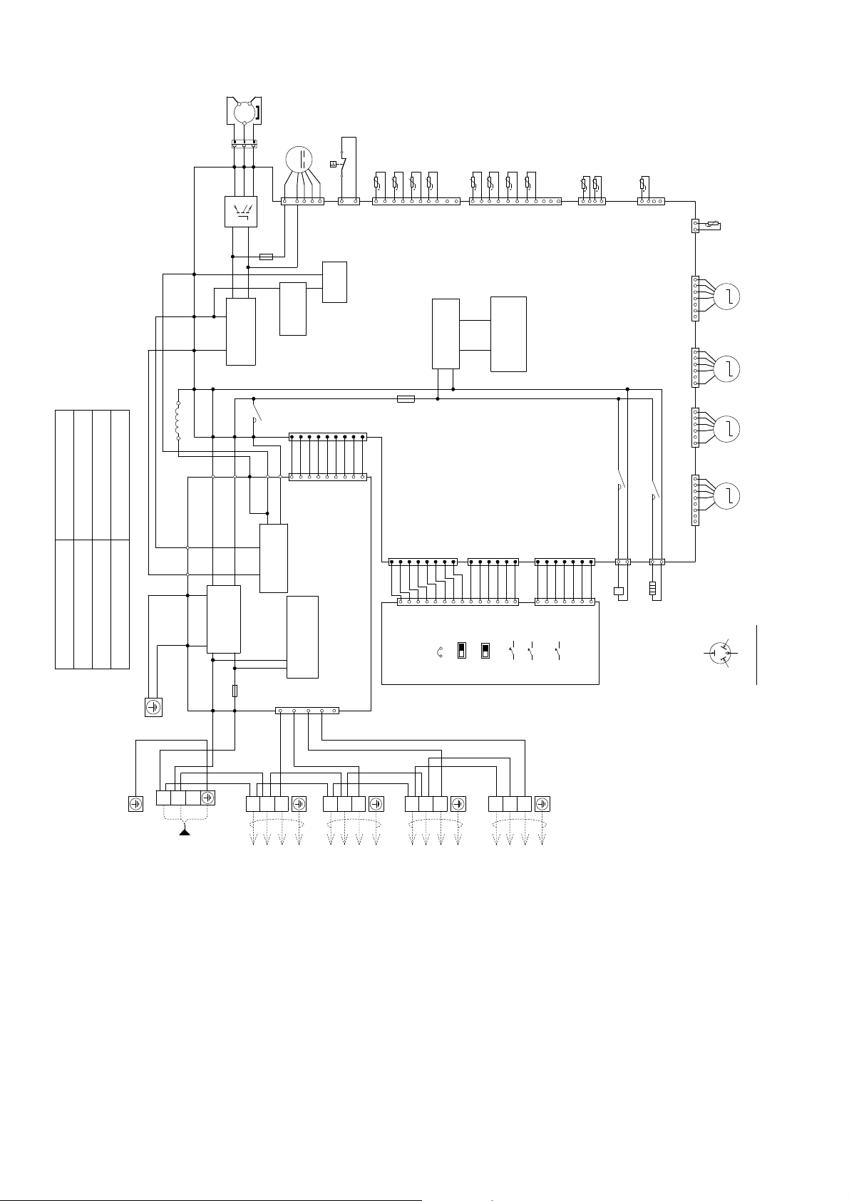
6.2 CU-4E24RBU
ResistanceofC
ompressor
Windings
CONNECTOR
WHITE
Q10
)
BROWN
AC1
(
)
BLACK
DCN
(
)
RED
DCP
(
RBLK
)
GRAY
RAT1
(
GRY
)
WHITE
AC-BLK
AC-WHT
(
REACTOR
W
CONTROL BOARD
FG2
FG1
DCN
DCP
CN-WHT
)
BLACK
(
)
RED
(
(GREEN)
(GREEN)
ACN1
)
WHITE
(
NOISE FILTER
(WHITE)
ACL1
0.72
0.73
0.71
5KD240XAL21 (Ω)
U-V
V-W
U-W
CONNECTION
G
G
Y/G
R
3
3
R
U
)
RED
(
U
P
)
BLACK
(
BLK
CN-BLK (BLACK)
CIRCUIT
(BLACK)
3~
MS
B
Y
COMPRESSOR
11
B
Y
V
W
)
BLUE
(
V
W
N
SMOOTHING
CAPACITOR
RY-PWR
GRY
RAT2 (GRAY)
FUSE 401
(30A 250V)
AC1
)
YELLOW
R
(
1
FUSE 1
(T3.15A L250V)
)
BLUE
AC2
(
BR
B
(BROWN)
AC2 (BLUE)
RECTIFICATION
CIRCUIT
1
R
M
FAN M OT OR
B
W
R
BR
ORG
1
7
4
CN-FM1
(WHITE)
CN-PSW1
PFC
CIRCUIT
PFC
CAPACITOR
WHITE
(
)
1
WWWWWWWWW
1
COMMUNICATION
357
B
CN-DATA
WHITE
(
)
CN-DATA
ELECTRONIC CONTROLLER
(NOISE FILTER)
CIRCUIT
(WHITE)
CN-COM
9
Y
ORG
LIQUID PIPE TEMP. SENSOR
(UNIT A) (THERMISTOR)
LIQUID PIPE TEMP. SENSOR
(UNIT B) (THERMISTOR)
LIQUID PIPE TEMP. SENSOR
(UNIT C) (THERMISTOR)
LIQUID PIPE TEMP. SENSOR
(UNIT D) (THERMISTOR)
HIGH PRESSURE SW.
t
t
t
R
1
2
(BLUE)
99
1
WWWWWWW
t
CN-TH3
(WHITE)
(T3.15A L250V)
FUSE 2
(WHITE)
CN-DISP1
CONTROLLER
(WHITE)
JP1
COOL ONLY
(DISPLAY)
1
ELECTRONIC
GAS PIPE TEMP. SENSOR
(UNIT A) (THERMISTOR)
GAS PIPE TEMP. SENSOR
(UNIT B) (THERMISTOR)
GAS PIPE TEMP. SENSOR
(UNIT C) (THERMISTOR)
GAS PIPE TEMP. SENSOR
t
t
t
t
1
10
CN-TH4
(WHITE)
CIRCUIT
RECTIFICATION
8
1
W
WWWWWWWWWWWWW
CN-DISP1
POWER SAVE
PRIORITY MO DE
SWITCHING
(WHITE)
CIRCUIT
POWER SUPPLY
CN-DISP2
6
14
PUMP DOWN
OPERATION TEST
(UNIT D) (THERMISTOR)
OUTDOOR TEMP.
SENSOR (THERMISTOR)
HEAT EXCHANGER TEMP.
SENSOR (THERMISTOR)
DEFROST TEMP.
t
t
1
11
ELECTRONIC CONTROLLER
(MAIN)
11
WIRING CHECK
4
CN-TH1
(WHITE)
RY-HOT
(YELLOW)
CN-NMODE
7
(BLUE)
CN-HOT
1
(WHITE)
7
CN-NMODE1
SENSOR (THERMISTOR)
t
1
4
12
CN-TH2
(YELLOW)
RY-HT
3
1
COIL (4-WAY VALVE)
ELECTRO MAGNETIC
t
CN-DIS
(WHITE)
1
(RED)
(BLUE)
(YELLOW)
(WHITE)
CN-HT
3
HEATER
MMMM
CN-EV4
7
CN-EV3
6
1
CN-EV2 1
6
1
CN-EV1
8
(BLACK)
RED (RED)
OR T (W)
YELLOW (YEL)
BLUE (BLU)
SENSOR (THERMISTOR)
DISCHARGE TEMP.
UNIT D
VALVE)
ELECTRO-
(EXPANSION
MAGNETIC COIL
UNIT C
VALVE)
ELECTRO-
(EXPANSION
MAGNETIC COIL
UNIT B
VALVE)
ELECTRO-
(EXPANSION
MAGNETIC COIL
UNIT A
VALVE)
ELECTRO-
(EXPANSION
MAGNETIC COIL
OR R (U)
(TRADEMARK)
COMP. TERMINAL
OR S (V)
INDICATED ON TERMINAL COVER
THE PARENTHESIZED LETTERS IS
CONTROL BOARD
BLK
INGLE PHASE
W
L1
L2
OWER SUPPLY
C 208/230V
60Hz
W
BLK
123
TERMINAL BOARD
TERMINAL BOARD
W
BLK
123
TO INDOOR UNIT A
BLK W
123
TO INDOOR U NIT B
BLK W
123
TO INDOOR U NIT C
TO INDOOR UN IT D
REMARKS
BLU/B : BLUE
BLK : BLACK
W : WHITE
R/RED : RED
Y/YEL : YELLOW
GRY : GRAY
G : GREEN
ORG : ORANGE
Y/G : YELLOW/GREEN
BR : BROWN
22

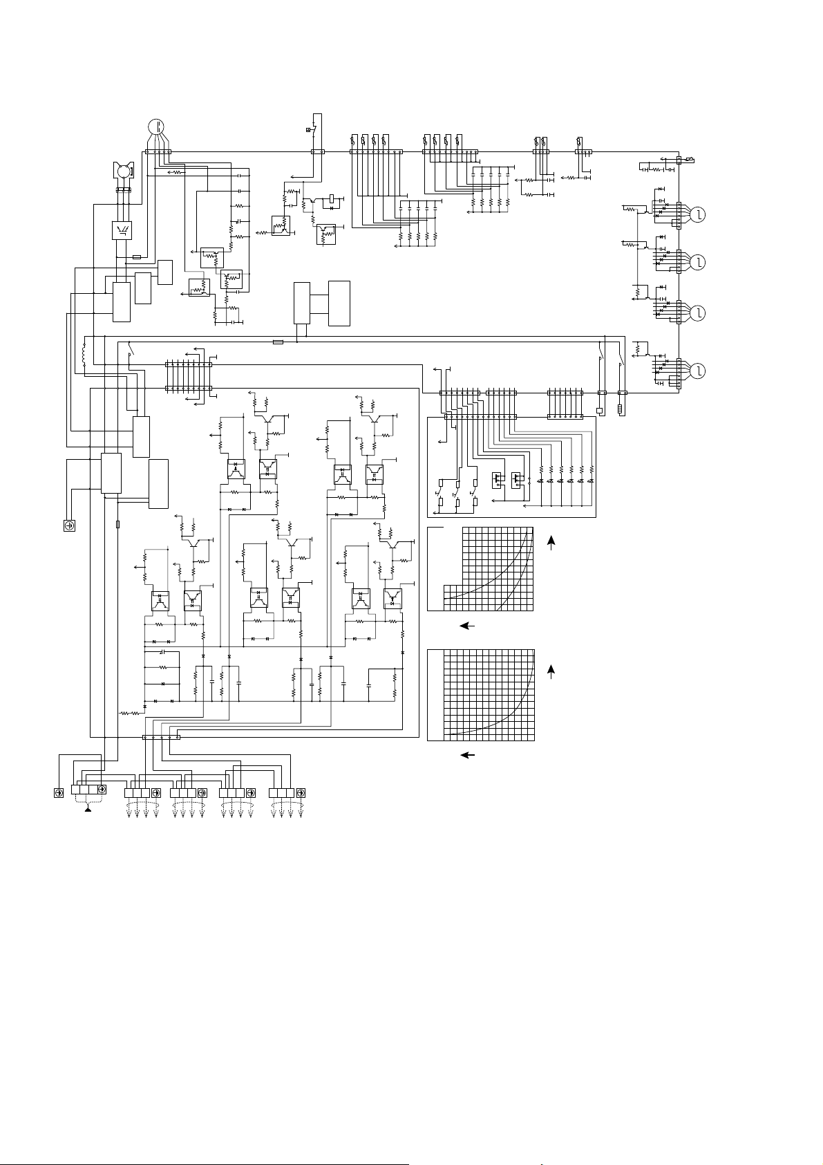
7. Electronic Circuit Diagram
7.1 CU-3E19RBU
3~
MS
COMPRESSOR
B
Y
R
33
11
R
B
Y
CONNECTOR
WHITE
V
U
W
)
)
)
RED
BLUE
(
(
YELLOW
(
U
V
W
P
N
Q10
L2-O
(BLK)
BLK
REACTOR
REACTOR
GRY
CONNECTOR
WHITE
1
1
BLK
GRY
BLK
L1-O
(BLK)
BLK
CIRCUIT
4
4
RECTIFICATION
L2-I
GRYGRY
(GRY)
L1-I
(GRY)
)
WHITE
AC-WHT
(
AC-BLK
W
)
WHITE
(
CN-WHT
CN-BLK (BLACK)
FG2
(GREEN)
NOISE FILTER
CIRCUIT
FG1
(GREEN)
G
G
ACL1
(BLACK)
ACN1
(WHITE)
)
BLACK
(
CN-FM1
(WHITE)
FUSE 1
(T3.15A L250V)
PFC
CIRCUIT
5V
)
WHITE
1
(
CN-DATA
BLK
)
WHITE
(
CN-DATA
FUSE 401
(30A 250 V)
CN-COM
(WHITE)
M
FAN MOTOR
Y
B
R
W
BLK
CN-PSW1
7
4
1
5V
e
15V_2
b
c
e
5V
13V
WWWWWWWWW
1
13V
5V
+
COMMU NICAT IO N
CIRCUIT
357
1
9
HIGH PRE SSURE SW.
R
R
1
2
(BLUE)
13V
b
c
c
b
c
b
FUSE 2
99
LIQUID PIPE TEMP. SENSOR (UNIT B) (THERMISTOR)
LIQUID PIPE TEMP. SENSOR (UNIT A) (THERMISTOR )
ttt
1
CN-TH3
(WHITE)
e
5V
e
(T2.5A L250V)
ELECTRONIC CONTROLLER
(NOISE FILTER)
LIQUID PIPE TEMP. SENSOR (UNIT C) (THERMISTOR) (5K, 3900)
ELECTRONIC CONTROLLER
ELECTRONIC CONTROLLER
10
(MAIN)
5V
1
WWWWWWW
1
(WHITE)
CN-DISP1
5V
5V
(DISPLAY)
GAS PIPE TEMP. SENSOR (UNIT A) (THERMISTOR)
GAS PIPE TEMP. SENSOR (UNIT B) (THERMISTOR)
GAS PIPE TEMP. SENSOR (UNIT C) (THERMISTOR) (5K, 3900)
t
t
t
t
t
1
CN-TH4
(WHITE)
5V
CIRCUIT
RECTIFICATION
3
4
SW1
PUMP DOWN
1
2
SWITCHING
CN-HOT
(WHITE)
CN-DISP1
8
1
W
WWWWWWWWWWWWW
3
4
3
4
SW2
1
2
1
2
WIRING CHECK
OPERATIONT EST
OUTDOOR TEMP. SENSOR (THERMISTOR) (15K, 3950)
114
11
CN-TH1
(WHITE)
5V
CIRCUIT
POWER SUPPLY
RY-HT
RY-HOT
(BLUE)
1
3
1
COIL
(4-WAY VALVE)
ELECTRO MAGNETIC
(WHITE)
CN-DISP2
11
6
14
SW3
SW4 POWERSAVE
5V
321
321
ON OFF
ON OFF
SW5 PRIORITY MODE
t
HEAT EXCHANGER TEMP. SENSOR (THERMISTOR) (5K, 3900)
DEFROST TEMP. SENSOR (THERMISTOR) (5K, 3900)
4
CN-TH2
(YELLOW)
5V
CN-DIS
(WHITE)
12
5V
t
b
(BLUE)
CN-EV3
c
e
e
13V
e
13V
CN-HT
(BLACK)
3
HEATER
(YELLOW)
CN-NMODE
(WHITE)
CN-NMODE1
COOL ONLY
*JP1
GREEN LED1
5V
1
6
b
b
GREEN LED2
CN-EV2
(YELLOW)
c
1
6
CN-EV1
(WHITE)
c
1
8
7
7
GREEN LED3
GREEN LED4
GREEN LED5
GREEN LED6
(50K, 3950)
SENSOR ( THERMISTOR)
DISCHARGE TEMP.
MMM
UNIT C
(EXPANSION VALVE)
ELECTRO-MAGNETIC COIL
UNIT B
(EXPANSION VALVE)
ELECTRO-MAGNETIC COIL
UNIT A
(EXPANSION VALVE)
ELECTRO-MAGNETIC COIL
B
Y
R
W
BLK
Y/G
W
BLK
L1
L2
TERMINAL BOARD
SINGLE PHASE
POWER SUPPLY
AC 208 /230 V 60Hz
TERMINAL BOARD
123
W
BLK
123
TO INDO OR UNIT A
W
BLK
123
TO INDOOR UNIT B
CONTROL BOARD
CABINETSIDEPLATE
Y/G
TO INDOOR UNIT C
Outdoor Air Sensor
Outdoor Heat Exchanger
Sensor
Characteristics
Sensor (Thermistor)
70
30
40
50
60
50
(122)
40
(104)
30
(86)
20
(68)
10
(50)
0
Temperature °C (°F)
(32)
-10
(40)
0
10
20
Resistance (K)
(Thermistor) Charateristics
Compressor Temp. Sensor
30
40
50
60
70
Resistance (K)
140
(284)
120
(248)
100
(212)
80
(176)
60
(140)
Temperature °C (°F)
40
(104)
20
(68)
10
20
23
7.2 CU-4E24RBU
T
L
S
M
FAN MOTO R
B
W
R
BR
ORG
CN-FM1
(WHITE)
7
4
1
3~
Y
Y
W
W
CAPACITOR
RY-PWR
GRY
(30A 250V)
ELECTRONIC CONTROLLER
R463
11
)
YELLOW
(
N
FUSE 1
AC2
BR
AC1
(BROWN)
5V
(NOISE FILTER)
CN-COM
123
R414
(WHITE)
COMPRESSOR
(T3.15A L250V)
)
BLUE
(
RECTIFICATION
R413
R401
D403
PFC
CAPACITOR
CN-DATA
B
CN-DATA
AC2 (BLUE)
CIRCUIT
1
PC401
4
ZD401
1
357
R
B
5V
R327
PFC
CIRCUIT
5V
)
WHITE
1
(
WWWWWWWWW
)
1
WHITE
(
COMMUNICATION
CIRCUIT
5V
R408
5V
R410
2
3
R402
ZD402
R404 C413
D401
ZD403
ZD404
9
Y
ORG
W
BLK
123
TO INDOOR UNI T A
e
15V_2
Q32
b
Q30
10k
e
5V
13V
13V
5V
R409
Q401
c
b
R412
R411
4
3
PC402
1
2
R403
R405
D402
R406 R407
C230C227C229R330
R332
R331R329
c
10k
4.7k
b
e
c
10k
4.7k
4.7k
Q31
b
c
C228
R326
R86
R328C231
99
5V
R423
R415
5V
5V
e
C414
R419
R420
1
2
PC404
4
3
R424
ZD407
ZD406
R431
5V
R435
1
PC405
4
D404
C415
R416 R417
BLK W
123
TO INDOOR UN IT B
R138
5V
R421
c
b
R426
4
PC403
1
R418
2
3
R438
ZD408
ZD409
BLK W
TO INDOOR UNIT C
MS
R
B
3
3
R
B
CONNECTOR
WHITE
V
U
)
)
RED
BLUE
(
(
U
V
P
Q10
)
BROWN
AC1
(
)
BLACK
DCN
(
)
RED
DCP
(
RBLK
SMOOTHING
)
GRAY
RAT1
(
GRY
)
)
BLACK
WHITE
AC-BLK
(
AC-WHT
(
REACTOR
BLK
W
)
WHITE
(
CN-WHT
)
RAT2 (GRAY)
CN-BLK (BLACK)
BLACK
DCN
(
)
RED
DCP
(
FG2
(GREEN)
G
NOISE FILTER
CIRCUIT
FG1
G
(GREEN)
CONTROL BOARD
FUSE 401
ACN1
(WHITE)
ACL1
(BLACK)
Y/G
W
BLK
BOARD
RO
W
BLK
L1
L2
CON
TERMINALBOARD
TERMINAL BOARD
SINGLE PHASE
POWER SUPPLY
AC 208/230V
60Hz
Q34
e
5V
5V
R139
b
10k
Q402
e
R425
3
2
R422
R429
R427
4
PC406
1
123
1
(BLUE)
CN-PSW1
13V
e
R132
b
C65 R140
R271
4.7k
c
CIRCUIT
RECTIFICATIO N
(T3.15A L250V)
FUSE 2
R430
Q403
c
e
b
R428
R437
3
2
R432
R436
D405
C416
R433 R434
TO INDOOR UNI T D
LIQUID PI PE TEMP. SENSOR
(UNIT A) (THERMISTOR)
LIQUID PI PE TEMP. SENSOR
(UNIT B) (THERMISTOR)
LIQUID PI PE TEMP. SENSOR
HIGH PRESSURE SW.
R
R
2
CN-TH3
RY-PWR
c
D78
c
Q24
10k
4.7k
b
SWITCHING
R446
5V
R440
1
PC408
4
ZD410
5V
D406
R445 R450
(UNIT C) (THERMISTOR)
ttt
1
(WHITE)
e
CIRCUIT
POWER SUPPLY
5V
R444
R442
c
b
5V
R449
R443
2
4
PC407
1
3
R439
R448
ZD411
R441
5V
R460
R459
5V
R454
R455
1
2
4
PC409
PC410
1
4
3
R452
ZD412
ZD413
C417
C418
GAS PIPE TEMP.SENSOR
(UNIT A) (THERMISTOR)
GAS PIPE TEMP.SENSOR
(UNIT B) (THERMISTOR)
GAS PIPE TEMP.SENSOR
(UNIT C) (THERMISTOR)
GAS PIPE TEMP.SENSOR
(UNIT D) (THERMISTOR)
t
ttt
C236
R337
5V
(WHITE)
1
CN-DISP1
WWWWWWW
(WHITE)
CN-DISP1
5V
ELECTRONIC
CONTROLLER
3
4
1
2
5V
Characteristics
Sensor (Thermistor)
(Thermistor) Charateristics
CompressorTemp. Sensor
(5k, 3900)
OUTDOOR TEMP.
SENSOR (THERMISTOR)( 15k, 3950)
HEATEXCHANGER TEMP.
SENSOR (THERMISTOR)( 5k, 3900)
DEFROST TEMP.
t
t
11
C239
C240
C235
R341
R342
R336
5V
1
8
W
WWWWW
1
(DISPLAY)
3
4
3
4
SW4 POWER SAVE
SW3
SW1
SW2
PUMP DOWN
1
2
5V
WIRING CHECK
1
2
OPERATIONTEST
Outdoor AirSensor
Outdoor HeatExchanger
Sensor
40
50
60
70
40
50
60
70
1
CN-TH1
(WHITE)
C237
C238
5V
C45
R100
C46
R101
R339
R340
ELECTRONIC CONTROLLER
(MAIN)
(WHITE)
1
(YELLOW)
6
CN-DISP2
CN-NMODE
W
WWWWWWW
1
14
R305
R304
COOL ONLY
JP1
321
321
ON OFF
ON OFF
SW5 PRIORITY MODE
GREEN LED2
GREEN LED1
5V
50
(122)
40
(104)
30
(86)
20
(68)
10
(50)
0
(32)
-10
(40)
0
10
20
30
Resistance (K)
140
(284)
120
(248)
100
(212)
80
(176)
60
(140)
40
(104)
20
(68)
10
20
30
Resistance (K)
SENSOR (THERMISTOR) (5k, 3900)
t
1
4
4
CN-TH2
(YELLOW)
5V
C48
R103
RY-HOT
(BLUE)
7
CN-HOT
1
(WHITE)
7
CN-NMODE1
R306
R307
R308
R309
GREEN LED3
GREEN LED4
GREEN LED5
GREEN LED6
C47
b
e
R368
Q27Q29Q26
b
e
R367
R366
e
13V
R365
e
13V
Q25
RY-HT
CN-HT
(BLACK)
3
3
1
HEATER
COIL (4-WAY VALVE)
ELECTRO MAGNETIC
CN-DIS
(WHITE)
12
5V
t
R102
C209
C220 D36
(RED)
CN-EV4
1
D69
D70
D71
c
MMMM
D72
7
(BLUE)
CN-EV3
c
1
D65
D66
D67
D68
6
b
CN-EV2
C218 D34 C219 D35
(YELLOW)
c
1
D61
D62
D63
D64
6
b
D33
CN-EV1
(WHITE)
c
1
D57
D58
D59
D60
C62
8
ENSOR (THERMISTOR) (50k, 3950)
DISCHARGE TEMP.
UNIT D
VALVE)
ELECTRO-
(EXPANSION
MAGNETIC COIL
UNIT C
VALVE)
ELECTRO-
(EXPANSION
MAGNETIC COI L
UNIT B
VALVE)
ELECTRO-
(EXPANSION
MAGNETIC COI L
UNIT A
VALVE)
ELECTRO-
(EXPANSION
MAGNETIC COIL
Temperature °C (°F)
Temperature °C (° F)
LIQUID PI PE TEMP. SENSOR
(UNIT D) (THERMISTOR)
(5k, 3900)
t
1
10
CN-TH4
(WHITE)
C232
C241
C233
C234
R333
R338
R334
R335
5V
Q404
e
R447
3
2
R451
Q405
c
e
b
R462
R457
3
2
R458
R461
D407
R453 R456
24
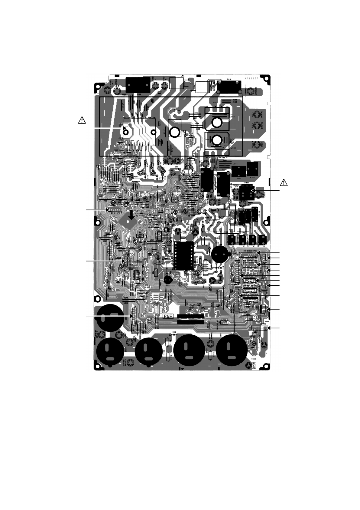
8. Printed Circuit Board
T
8.1 Main Printed Circuit Board
8.1.1 CU-3E19RBU
POWER
RANSISTOR
(IPM)
CN-DISP2
CURRENT
TRANSFORMER
(CT)
CN-EV1
CN-NMODE
CN-DISP1
CN-TH1
CN-EV2
CN-DIS
CN-TH3
CN-EV3
CN-TH2
CN-TH4
CN-PSW1
CN-FM1
25
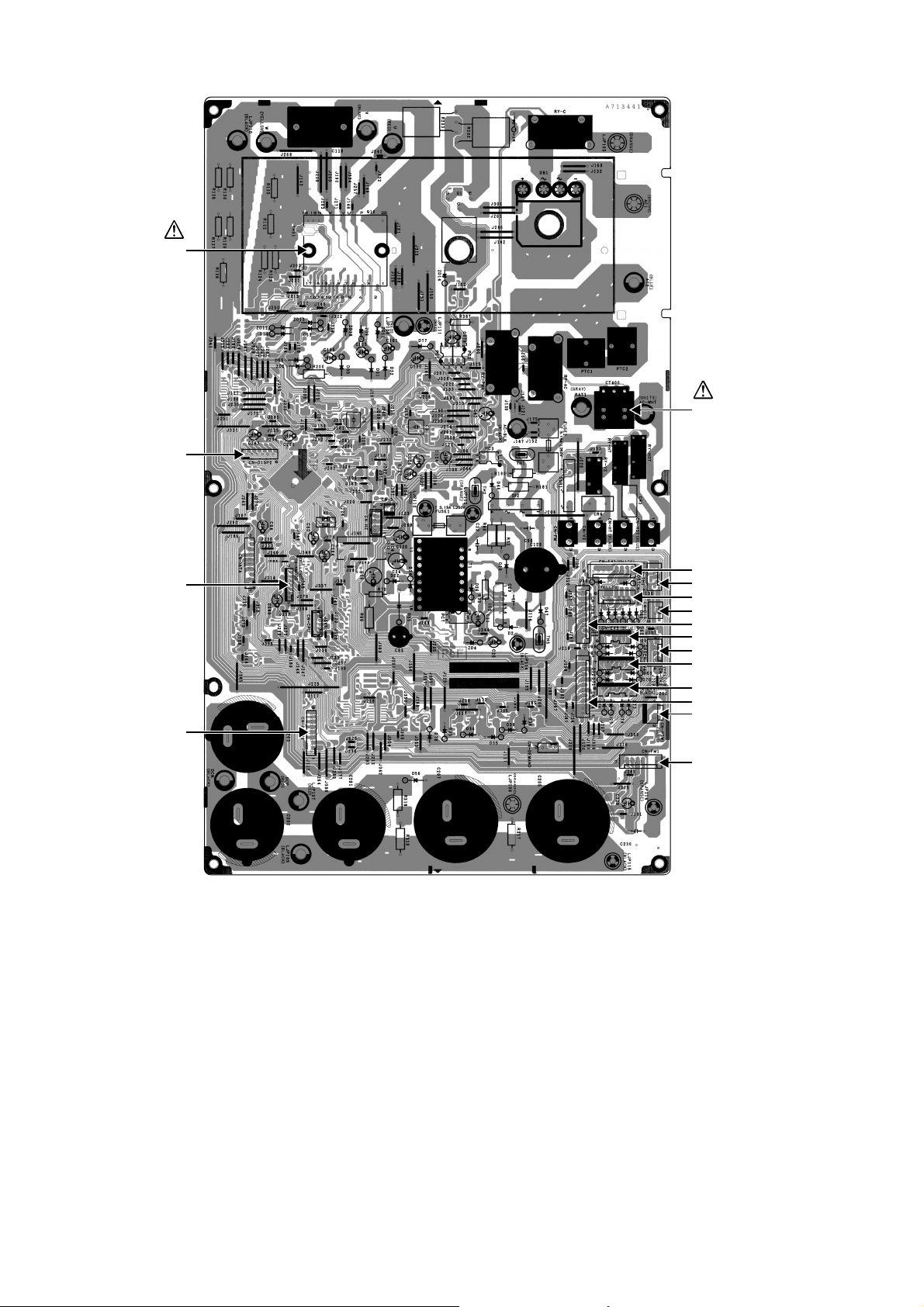
8.1.2 CU-4E24RBU
T
POWER
RANSISTOR
(IPM)
CN-DISP2
CURRENT
TRANSFORMER
(CT)
CN-EV1
CN-NMODE
CN-DISP1
CN-TH1
CN-EV2
CN-DIS
CN-TH3
CN-EV3
CN-TH2
CN-EV4
CN-EV5
CN-TH4
CN-PSW1
CN-FM1
26
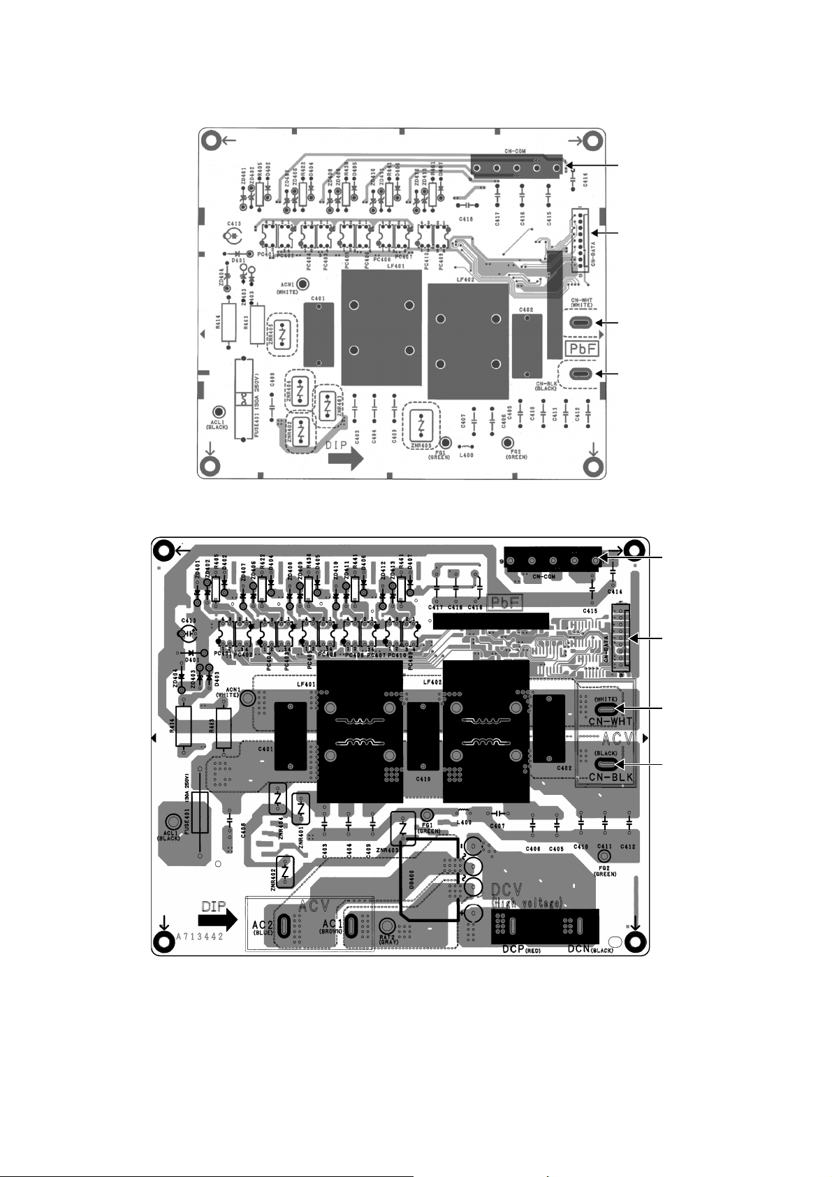
8.2 Noise Filter Printed Circuit Board
8.2.1 CU-3E19RBU
CN-COM
CN-DATA
CN-WHT
CN-BLK
8.2.2 CU-4E24RBU
CN-COM
CN-DATA
CN-WHT
CN-BLK
27
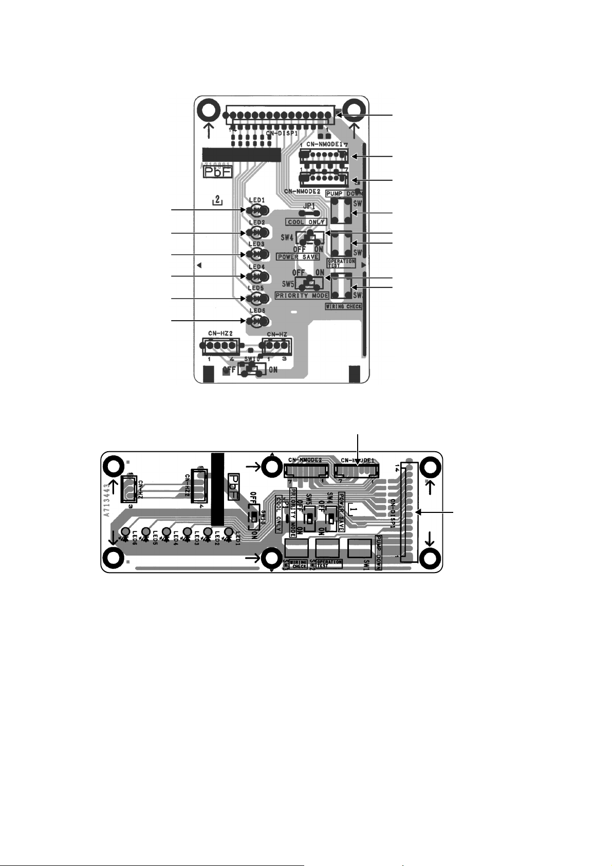
8.3 Display Printed Circuit Board
1
8.3.1 CU-3E19RBU
CN-DISP1
CN-NMODE1
CN-NMODE2
LED1
LED2
LED3
LED4
LED5
LED6
8.3.2 CU-4E24RBU
SW1
SW4
SW2
SW5
SW3
CN-NMODE
CN-DISP1
28
9. Installation Information
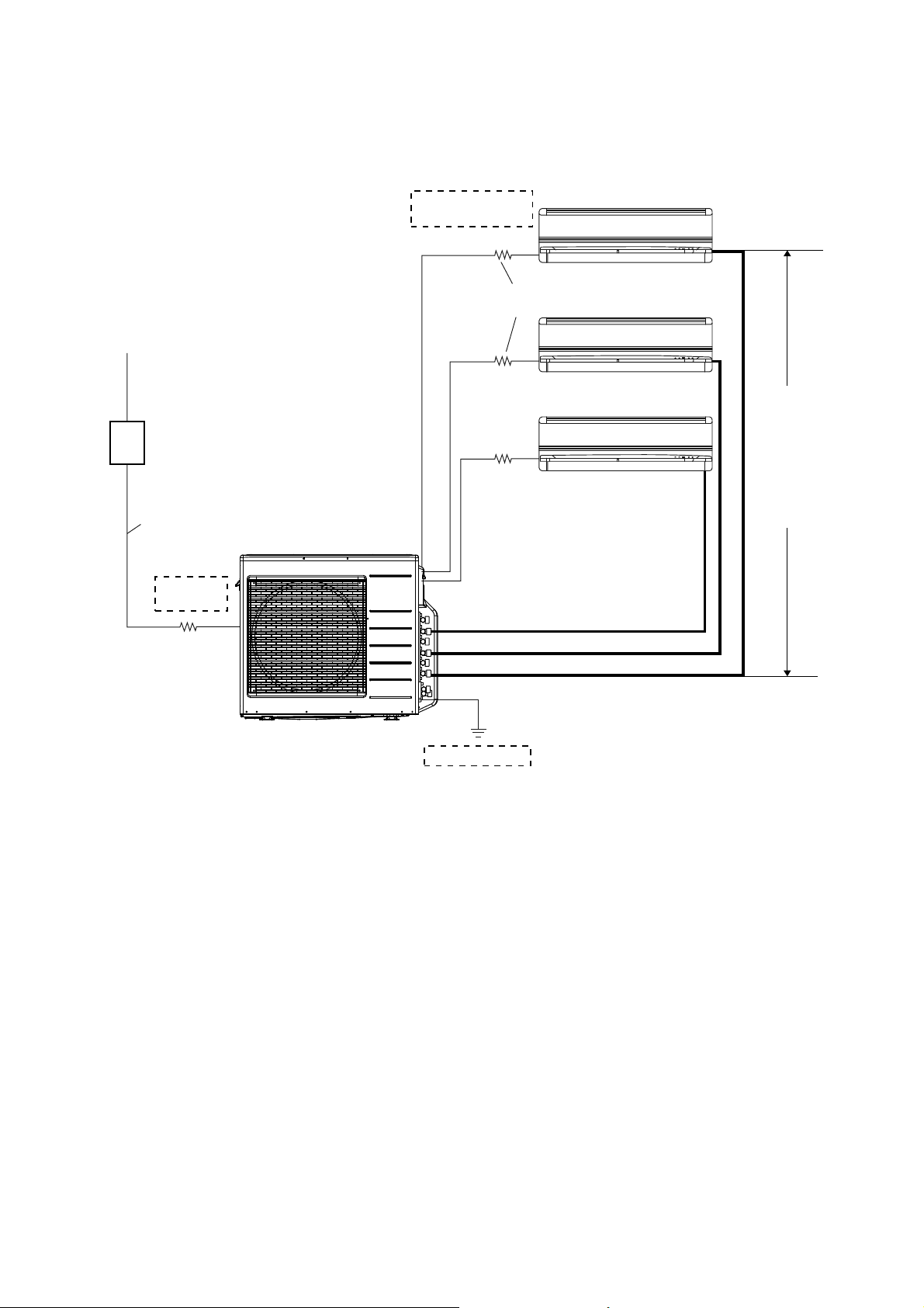
9.1 CU-3E19RBU
9.1.1 Check Points
Indoor/outdoor unit
connection cables
(Not included in the unit)
Outdoor unit power supply:
Single-phase 208-230V, 60Hz
30A switch
(circuit breaker)
(Not included in the unit)
Flexible cord x 3 core
(Not included in the unit)
Outside
wiring work
Unit C
Unit A Maximum pipe length: 25 m (82.0 ft)
Unit B Maximum pipe length: 25 m (82.0 ft)
Unit C Maximum pipe length: 25 m (82.0 ft)
Flexible cord x 4 core
(polychloroprene sheathed)
(Not included in the unit)
Unit B
Flexible cord x 4 core
(polychloroprene sheathed)
(Not included in the unit)
Unit A
Applicable connecting tube kit:
CZ-3F type
Total maximum pipe length: 50 m (164.0 ft)
Allowable
elevation:
15 m (49.2 ft) max.
The allowable
elevation between
each of the indoor
units and between
the indoor and
outdoor units.
Grounding work
Air purging: Air purging by vacuum pump.
29
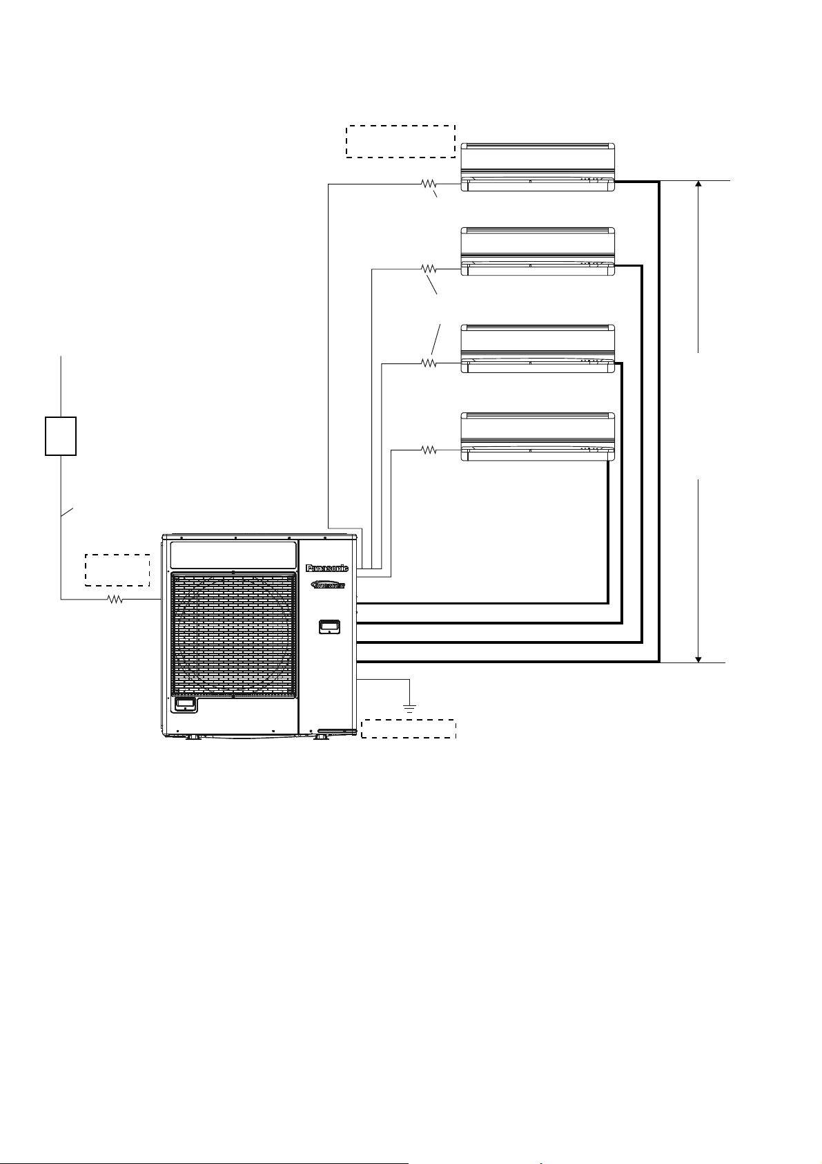
9.2 CU-4E24RBU
9.2.1 Check Points
Indoor/outdoor unit
connection cables
(Not included in the unit)
Flexible cord x 4 core
Unit D
(Not included in the unit)
(polychloroprene sheathed)
Outdoor unit power supply:
Single-phase 208-230V, 60Hz
45A switch
(circuit breaker)
(Not included in the unit)
Flexible cord x 3 core
(Not included in the unit)
Outside
wiring work
Unit C
Unit A Maximum pipe length: 25 m (82.0 ft)
Unit B Maximum pipe length: 25 m (82.0 ft)
Unit C Maximum pipe length: 25 m (82.0 ft)
Unit D Maximum pipe length: 25 m (82.0 ft)
Flexible cord x 4 core
(polychloroprene sheathed)
(Not included in the unit)
Unit B
Flexible cord x 4 core
(polychloroprene sheathed)
(Not included in the unit)
Unit A
Applicable connecting tube kit:
CZ-3F type
Total maximum pipe length: 70 m (229.6 ft)
Allowable
elevation:
15 m (49.2 ft) max.
The allowable
elevation between
each of the indoor
units and between
the indoor and
outdoor units.
Grounding work
Air purging: Air purging by vacuum pump.
30
 Loading...