

Panasonic CS-W34BB4P, CU-V34BBP5, CU-W34BBP5 Service Manual
1 SERVICE INFORMATION 3
2 FEATURES
4
3 SPECIFICATION (HEAT PUMP TYPE )
10
4 SPECIFICATION (COOLING ONLY TYPE )
11
5 TECHNICAL DRAWING
12
6 CIRCUIT DIAGRAM
14
7 OPERATING INSTRUCTION
26
© 2002 Matsushita Industrial Corporation Sdn. Bhd.
(11969-T). All rights reserved. Unauthorized copying
and distribution is a violation of law.
CS-W34BB4P CU-V34BBP5
CS-W34BB4P CU-W34BBP5
8 REFRIGERATION CYCLE 28
9 OPERATION RANGE
29
10 PIPE LENGTH
30
11 OPERATING CHARACTERISTIC
32
12 FAN PERFORMANCE
33
13 SAFETY DEVICE
34
AIR CONDITIONER
CONTENTS
Page Page
ORDER NO. MAC0208027C2

14 COMPONE NT SPECIFICATION 35
15 CAPACITY AND POWER CONSUMPTION
36
16 DISCHARG E AND SUCTION PRESSURE
38
17 SOUND DATA
39
18 TWIN AND TRIPLE
41
19 WIRING MISTAKE PREVENTI ON
46
20 TEST OPERATIO N AND SELF DIAGNOSI S
47
21 SETTING OF SAVE ENERGY AND THERMISTOR SWITCH
51
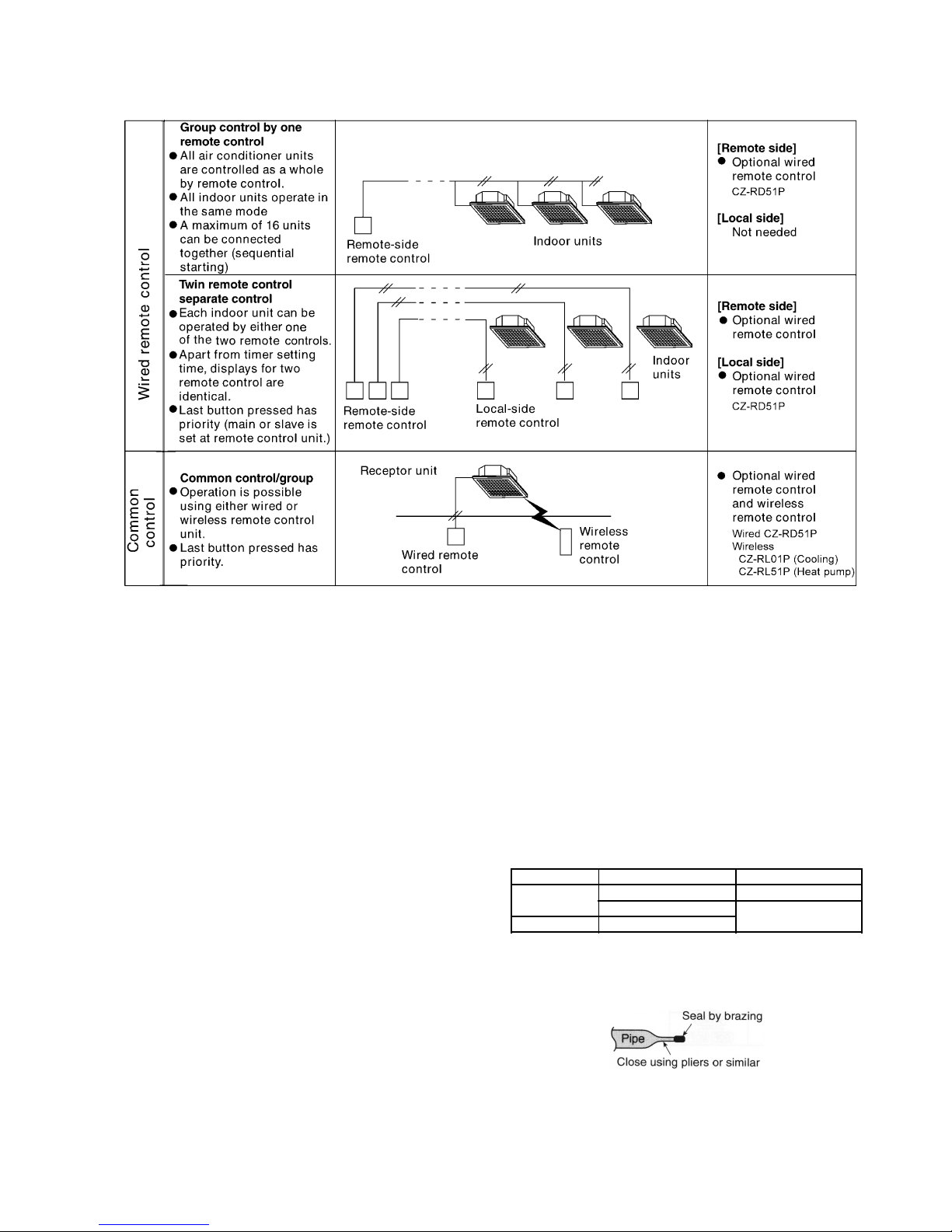
22 GROUP CONTROL
52
23 TROUBLESHOOTING
53
24 EMERGEN CY OPERATIO N
58
25 CONTROL
59
26 WIRED REMOTE CONTROL INSTALLATION MANUAL
71
27 WIRELESS REMOTE CONTROL INSTALLATION MANUAL
76
28 INSTALLATION (INDOOR UNIT)
83
29 INSTALLATION (OUTDOOR UNIT)
92
30 REPLACEM E NT PARTS
103
2

1 SERVICE INFORMATION
Caution:
●
Pb free solder has a higher melting point than standard solder; Typically the melting point is 50 - 70°F (30 - 40°C) higher. Please
use a high temperature soldering iron. In case of the soldering iron with temperature control, please set it to 700 ± 20°F (370 ±
10°C).
●
Pb free solder will tend to splash when heated too high (about 1100° F/600°C).
Notice of Address setting for NEW Cassette / NEW Outdoor Unit.
The new Cassette / new Outdoor models are possible to have address setting for twin / triple control or group control
automatically when main power supply is switched on.
(Manual address setting is also possible by using DSW1 switch on the indoor unit P.C. board.) However,
this address setting is
only possible when proper wiring connection is made and indoor unit must be of original unit
.
1.1. Example of trouble during test operation
If the below phenomenon is found during test operation, wrong address setting is possible.
Therefore, please inspect the address setting.
1. LCD display of the wired remote control is not illuminated although the main power supply switch is ‘on’.
2. LCD display had indicated as normal illumination when power supply switch is ‘on’, however outdoor unit cannot be operated.
(But, it is necessary to take 3 to 5 minutes for outdoor unit to start from the timing of remote control OFF/ON button is ‘on’.)
(For normal operation, the outdoor unit will only start its operation after 3 to 5 minutes upon pressing the OFF/ON button.)
3. P.C. board had memorized wrong setting information.
a. If main power supply is switched on with the wrong connection.
b. When changing the connection or combination of units due to re-installation etc.
•
• •
•
When changing the system from twin to triple (triple to twin).
•
• •
•
When changing the system from group control to normal one to one system.
•
• •
•
When making the replacement of units of master and slave etc.
1.2. Caution during test operation
Do not touch the remote control button and do not change any wirings for one minute when the main power supply switch is ‘on’.
(Because the unit is having automatic address setting during the first one minute.)
1.3. Caution during automatic address setting
When the main power supply switch is ‘on’, the P.C. board will automatically memorize the connecting system.
Consequently, when initial power supply is ‘on’, there mustn’t be any interchanging of units even of the same type and same
capacity unit.
Therefore, connection of the unit to another system is prohibited.
3
2.1. Variety of excellent features
•
• •
•
Compact design
Compact design 290 mm height, 840 mm width and 840
mm depth.
•
• •
•
Automatic restart function
When the electric power resumes after a power failure, the
unit will automatically restarts the operation in the prefailure mode.
•
• •
•
Auto fan mode (indoor unit)
Auto fan mode is added besides HI, ME and LO.
It automatically adjusts the fan speed according to the
indoor temperature.
•
• •
•
Dry mode function
Dry mode can make a comfor table indoor environment
during wet season.
•
• •
•
Quiet operation
The sound level is 45dB (A) for 34BB model during High
Fan speed and suitable for offices, shops, homes etc, when
quiet operation is essential.
•
• •
•
Auto Swing Louvre
The air flow angle can be changed automatically (or
manually) to an angle between 10° to 70° using the remote
control.
•
• •
•
Low ambient cooling operation
Cooling operation is possible at outdoor temperature of
-5°C.
•
• •
•
Automatic changeover function (heat pump models)
The unit automatically switches between cooling and
heating in accordance with operating load in order to
maintain a comfortable indoor temperature.
•
• •
•
Hot start system (heat pump models)
•
• •
•
Pipes and drainage
Built-in upward draining mechanism.
2 FEATURES
2.2. Low-noise outdoor units
4
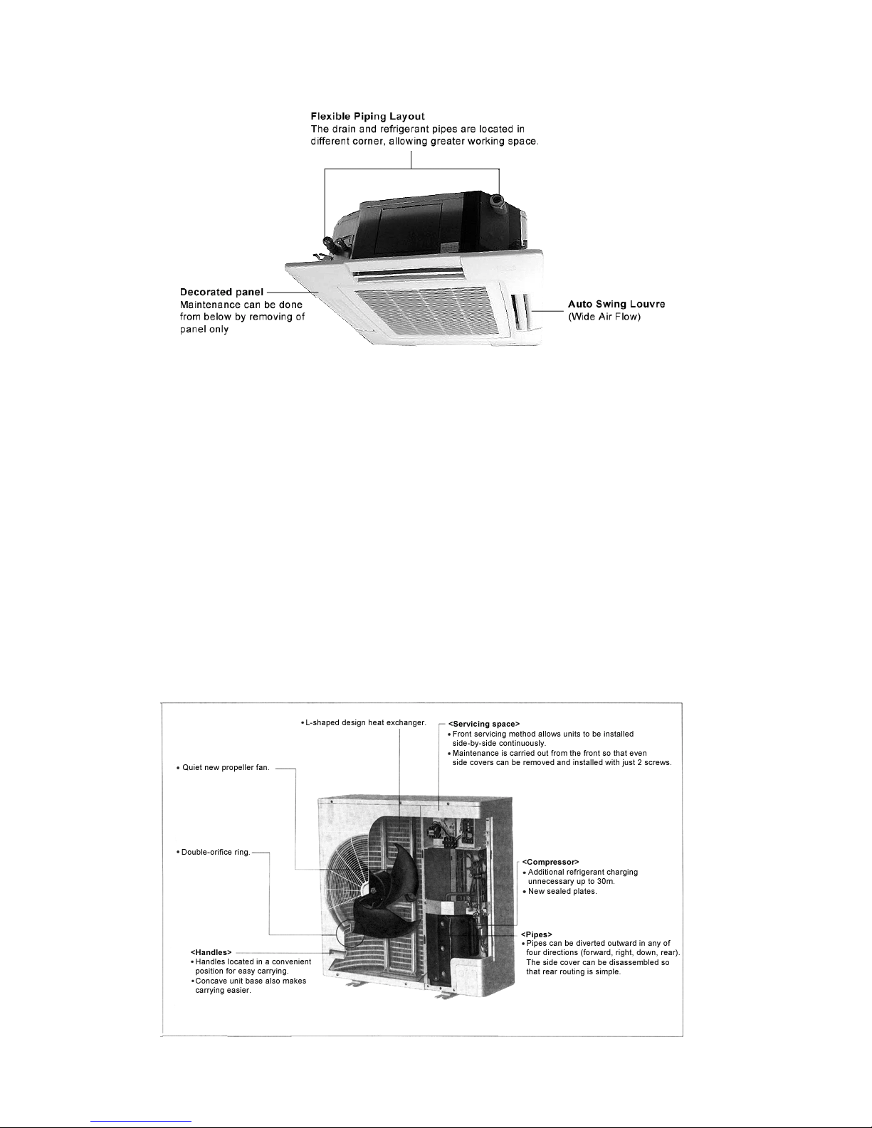
2.2.1. Product features
•
• •
•
Low-noise design improves comfort in surrounding
areas
1. The noise-suppressing winglet fan is a result of new
research into vane design theory. The unique curved
shape suppresses the generation of vortexes, thus
reducing air flow noise.
2. The adoption of double-orifice rings reduces air
passage resistance.
3. Strengthening of the noise insulation materials in the
compressor and the sealing-in of mechanical noise
allows vibration noise to be greatly enclosed and
suppressed.
4. The heat exchanger has an L-shaped design to allow air
to flow more smoothly.
5. Noise is automatically reduced further during night-time
operation with lower outdoor air temperatures.
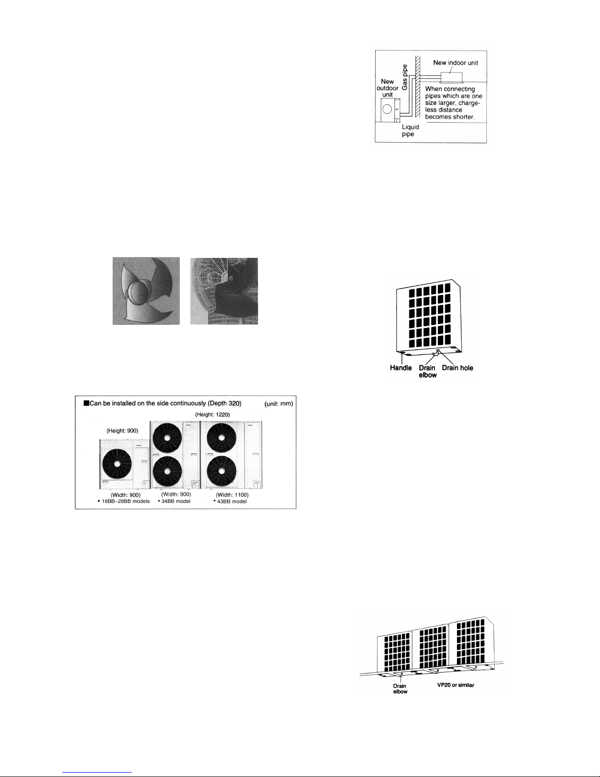
2.3. Greatly improved workability
increases system renewal
capability
•
• •
•
Pipes that are one size larger can also be connected for
renewal.
−
− −
− If renewing the system, existing refrigerant pipes can be
utilized so that only the indoor and outdoor units need to
be replaced.
−
− −
− For example, liquid and gas pipes from 10 years ago
can be connected to current pipes with the same size or
one size larger. Effective utilization of materials reduces
working time and trouble. (Adaptor sockets are not
supplied.)
•
• •
•
Additional refrigerant charging unnecessary for 30 m
−
− −
− All models do not require any additional charging of
refrigerant for 30 m of pipe length. This makes
installation much easier.
•
• •
•
Drain water dripping-prevention structure
−
− −
− The base of the outdoor unit is provided with a single
drain hole in order to prevent drain water from leaking
out of the unit. By connecting a drain elbow and a
discharge pipe, water leakages can be prevented even
when the unit is installed to a wall.
•
• •
•
Save space design allows units to be installed side-byside continuously
−
− −
− Servicing after installation can be carried out by
removing the front covers.
•
• •
•
Long pipe design for refrigerant pipes
−
− −
− Maximum piping length of 50m for all models.
•
• •
•
Internal pipe connection
−
− −
− Pipes are connected inside the units (inside the side
covers), making the final appearance more attractive.
−
− −
− Pipes can be diverted outward in any of four directions
(forward, right, down, rear).
−
− −
− Small liquid pipe diameters of 9.52mm for 34BB model,
making installation work much easier.
•
• •
•
Centralized draining method
−
− −
− Even when multiple outdoor units are installed to a wall,
the drain outlets can be concentrated into a single drain
pipe. This makes installation easier and also improves
appearance.
5
2.4. A brand-new control method
using the latest in technology
•
• •
• Easier power supply wiring connection
Power supply wiring and other wiring tasks can be carried
out more easily.
−
− −
− Twin non-polar wires used to connect indoor and
outdoor units.
−
− −
− Adoption of connection error prevention circuits for drive
wires and signal wires. If a connection error is made, the
relay does not operate and current does not flow to the
circuit boards.
•
• •
•
Twin and Triple operation
−
− −
− Simultaneous air conditioning of wide spaces and
corners is possible. Indoor units of different
horsepowers can even be used in combination.
−
− −
− Master unit and slave-units can be set automatically in
twin and triple systems. No address setting is
necessary.
−
− −
− Multiple indoor units can be operated simultaneously
with a single remote control. Note that individual
operation is not possible.
•
• •
•
Separate indoor/outdoor unit power supplies
The power supply can be connected to (1) just the outdoor
units, or (2) to both the indoor and outdoor units.
•
• •
•
Easy test operation
Test operation can be carried out for both indoor and
outdoor units.
•
• •
•
Automatic setting initialization function
(Remote control
and Indoor unit)
In accordance with the indoor and outdoor units connected
and the connection methods, conditions such as the
connection configuration (twin or triple format) and remote
control functions such as automatic louvre operation and
cooling or heating mode are automatically detected and set
instantly.
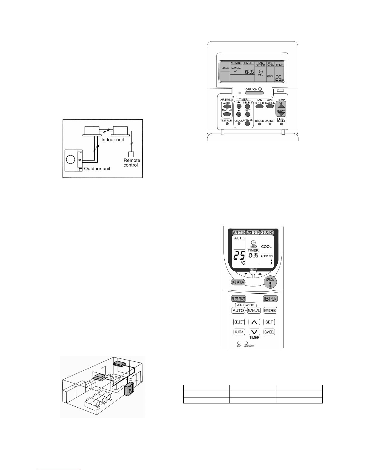
2.5. Wired Remote Control
•
• •
• The new design includes an easily-visible red pilot lamp.
The power can be turned on and off at a single touch,
without opening the cover.
•
• •
• Has a built-in thermistor, allowing indoor temperature
detection in accordance with indoor conditions by switching
with main unit thermistor.
•
• •
• Twin non-polar wires make installation work easy. (10 m
cable supplied as accessory.)
2.6. Wireless Remote Control
•
• •
• New design with compact size. (Operation range within
approximately 8 m.)
•
• •
• Built-in timer with ON/OFF timer setting (within 24 hours)
Wired Wireless
Heat Pump CZ-RD51P CZ-RL51P
Cooling CZ-RD51P CZ-RL01P
NOTE: Both of the above remote control is packed separately
from the indoor unit.
6
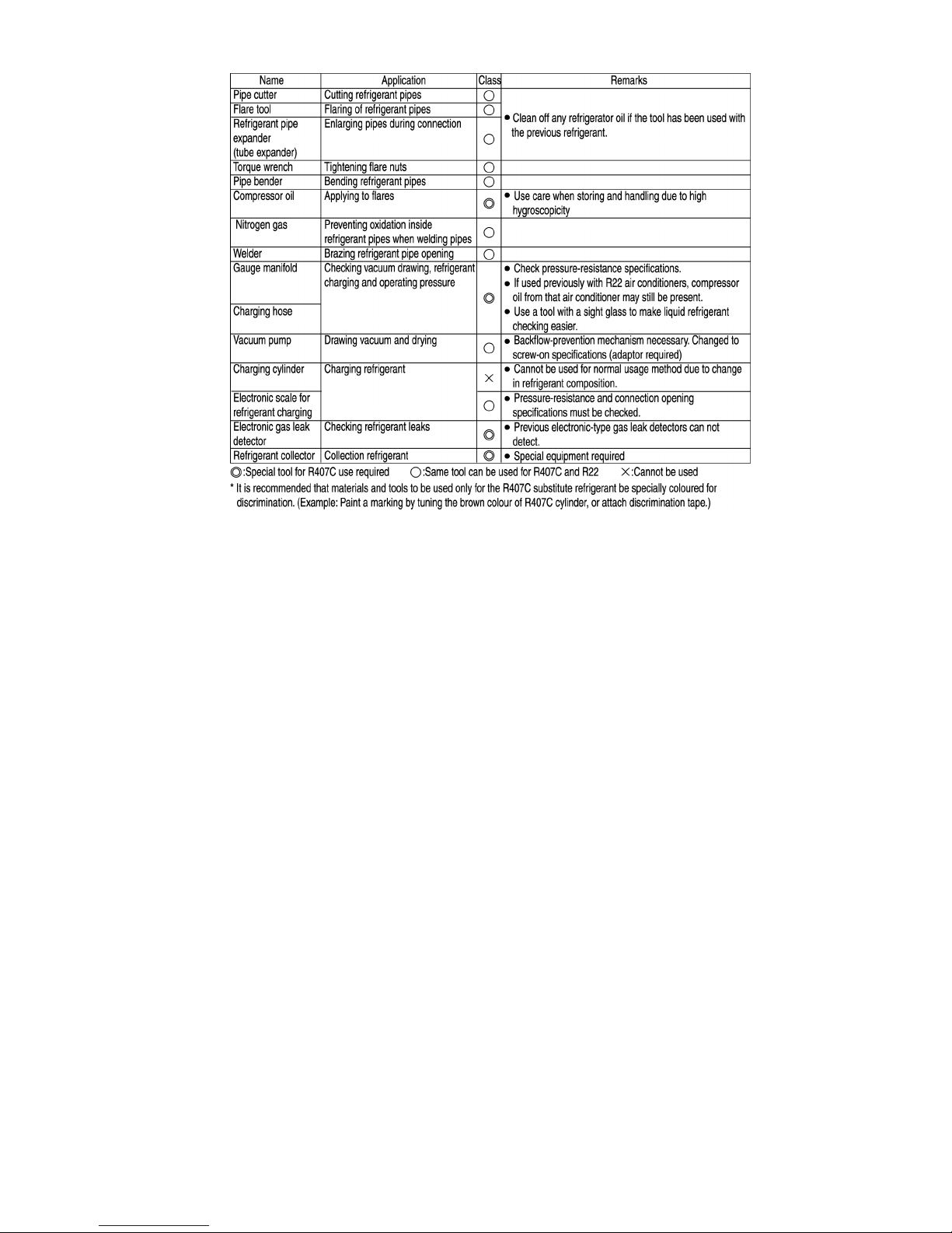
2.8. New refrigerant Series [R407C]
pipe installation
2.8.1. Procedure
•
• •
• The new refrigerant (R407C) has a different composition to
the previously-used refrigerant (R22), so some contents
and method of pipe installation and charging work are
different from before. Care should be taken when carrying
out this work.
2.8.2. Installation and precautions
2.8.2.1. Before installation
1. Determine the installation division.
2. Check the refrigerant to be used.
•
• •
• Check that the refrigerant is R407C.
•
• •
• Check that the gauge pressure is at a maximum of 3.3
MPa.
3. Make a drawing of the Installation.
2.8.2.2. Installation
1. Install the sleeve and the insert.
2. Install the indoor unit.
3. Install the refrigerant piping.
•
• •
• Pipe materials (Phosphours Deoxidization Seamless
Pipe)
•
• •
• Refrigerant pipes which were previously used to carry
R22 must not be re-used. If replacing the indoor and
outdoor units, be sure to replace all refrigerant pipes
also.
•
• •
• Check the pipe thickness.
(1/4, 3/8, 1/2 : t = 0.8mm 5/8, 3/4 : t = 1.0mm)
•
• •
• Clean the inside of the pipes.
•
• •
• When storing pipes, seal both ends of the pipes and
store them indoors to prevent water, dust and other
foreign particles from getting inside.
•
• •
• Take care not to let any foreign particles (oxide scales,
water or dirt) get inside the refrigerant lines (same as for
R22).
■
Refrigerant pipe storing
Location Installation period Storing method
Outdoors 1 month or more Pinching
Less than 1 month Pinching or taping
Indoors Any
•
• •
• Pinching method
Close off the ends of the pipes with pliers or similar tool
and seal the opening by brazing.
•
• •
• Taping method
Wind PVC tape around the ends of the pipes to seal the
2.7. Group Control Equipment
7
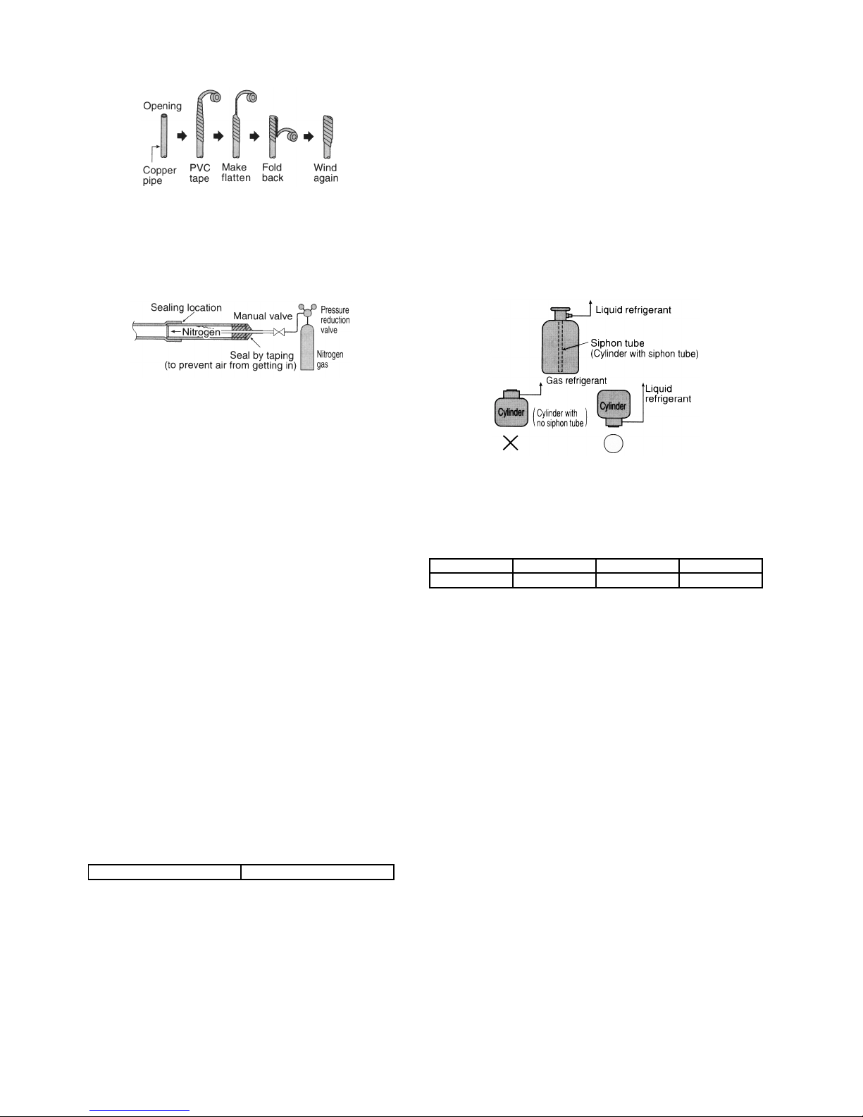
openings.
•
• •
• Do not work for refrigerant piping on outdoor on rainy
days.
•
• •
• Seal by brazing.
•
• •
• Be sure to use only a non-oxidizing brazing material.
(Use nitrogen. Anti-oxidants cannot be used.)
•
• •
• When brazing pipes together, or when brazing copper
pipes and copper joints, use a brazing material (Bcup-3)
which does not require flux.
•
• •
• Flare processing and ester oil.
•
• •
• Sealing can be improved by applying ester oil or mineral
oil (the minimum amount necessary) to flares and flange
connections.
•
• •
• Due to the high hygroscopic tendency for ester oil, do
not mix or use any other impurities. (This can cause
deterioration of the compressor oil and problems with
the compressor.)
•
• •
• After preparing the refrigerant pipes, close both ends of
the pipes by brazing if not immediately connecting them.
•
• •
• A torque wrench must be used.
4. Install the drain pipe.
5. Install the ducts.
6. Insulate against heat.
7. Carry out the electrical work.
•
• •
• Connecting cables and power cables.
8. Make all necessary settings.
9. Prepare the outdoor unit foundation.
10. Install the outdoor unit.
11. Air-tightness test.
For the final check, there should be no pressure drop when
3.3 MPa is applied for 24 hours.
12. Vacuum drying.
Vacuum draw time 60 min. or more
* Vacuum pump capacity 60 l/min. or higher
•
• •
• D rawing the vacuum will remove any moisture.
•
• •
• The pressure after vacuum drawing should be 755
mmHg or less.
•
• •
• Use a special vacuum pump (with backflow-prevention
mechanism).
•
• •
• Gas must never be used for air purging.
13. Additional refrigerant charging.
•
• •
• Check that refrigerant volume is correct.
•
• •
• Be sure to charge refrigerant in liquid state.
•
• •
• Always charge in liquid state.
When the refrigerant is charged from the cylinder, the
composition may change greatly (compounds which do
not easily evaporate may remain inside the cylinder), so
the refrigerant must always be charged in a liquid state.
(It is recommended that a manifold with sight glass be
used.)
■ Boiling point at normal atmospheric pressure
(reference)
Refrigerant HFC32 HFC125 HFC134a
Boiling point -52°C -49°C -26°C
•
• •
• Use a special gauge manifold and charging hose.
•
• •
• If refrigerant leaks occur, replace all of the refrigerant
(same as for R22).
•
• •
• Note that a R22 leak detector cannot be use to detect
leaks.
•
• •
• Refer to the Installation Instructions included for the
correct charging amount.
•
• •
• Make a note of additional refrigerant charging amounts
in the record table.
14. Test operation and adjustment.
15. Organize documentation before handover.
16. Handover and explanation of operation.
•
• •
• Ventilation of closed rooms
R407C is a non-flammable refrigerant with low toxicity,
but in the gas state its specific gravity is heavier than
that of air, and so if leaks occur in a closed room,
suffocation may occur. Toxic gases may also be
generated if it comes into direct contact with flames, so
adequate ventilation must be provided.
8
9
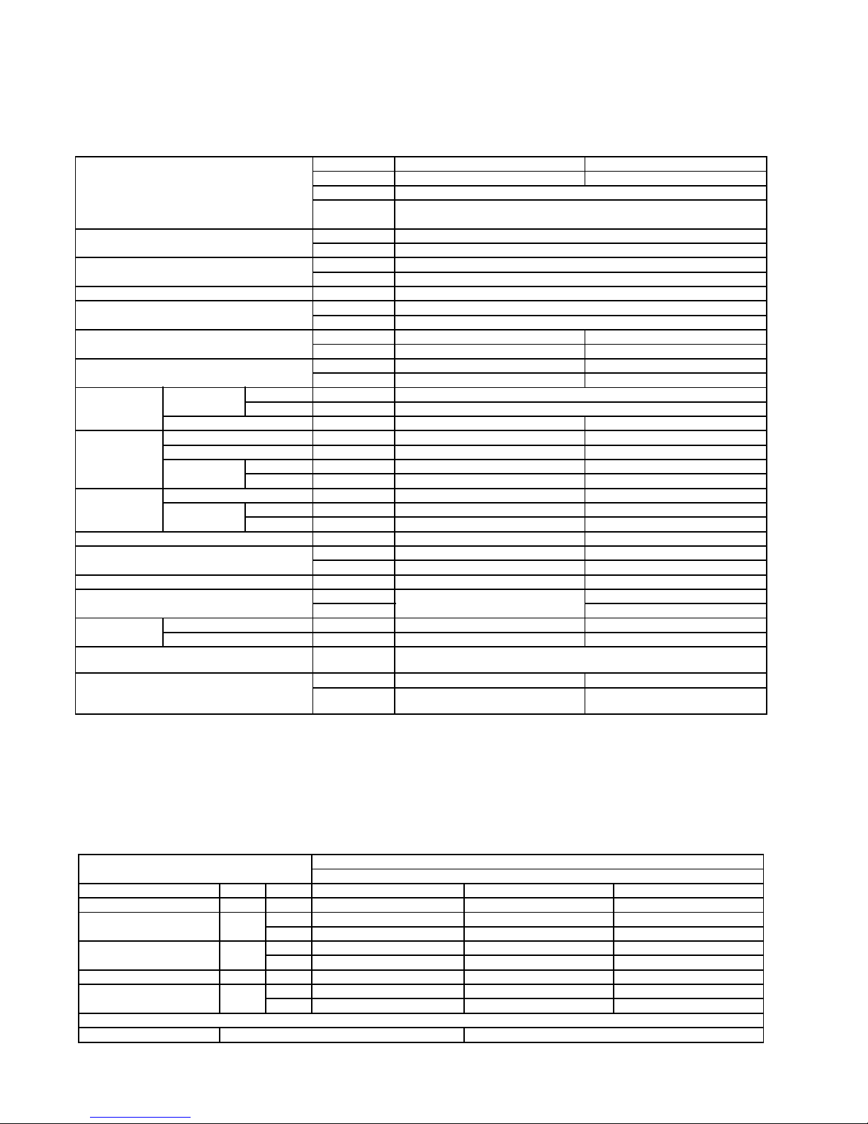
3 SPECIFICATION (HEAT PUMP TYPE )
3.1. CS-W34BB4P / CU-W34BBP5
ITEM / MODEL Indoor Unit Outdoor unit
Main Body CS-W34BB4P CU-W34BBP5
Panel CZ-BT01P
Remote CZ-RD51P (Wired)
Control CZ-RL51P (Wireless)
Cooling Capacity kW 10.0
BTU/h 34,100
Heating Capacity kW 11.2
BTU/h 38,200
Refrigerant Charge-less m 30
Standard Air Volume for High Speed m3/min 23
cfm 812
Outside Dimension (H x W x D) mm 290 x 840 x 840 1220 x 900 x 320
inch 11-7/16 x 33-1/24 x 33-1/24 48-1/24 x 35-7/16 x 12-19/32
Net Weight kg 30 97
lbs 66 214
Piping
Connection
Refrigerant Gas mm (inch) O.D Ø 19.05 (3/4) Flared Type
Liquid mm (inch) O.D Ø 9.52 (3/8) Flared Type
Drain mm O.D Ø 32 I.D Ø 20 x 1
Compressor Type, Number of Set - Hermetic-1 (Rotary), 1
Starting Method - Direct on-line starting
Motor Type - 2-pole 1-phase induction motor
Rated Output kW - 3.0
Fan Type, Number of Set Turbo fan Propeller fan
Motor Type 6-pole single phase induction motor 6-pole single phase induction motor
Rated Output kW 0.05 0.05 x 2
Air-heat Exchanger Slit-fin type X-Louvre-fin type
Refrigerant Control Cool Capillary tube -
Heat - Capillary tube
Refrigerant Oil (Charged) litre - MMMAPOE (1.2)
Refrigerant (Charged) kg - R407C (3.2)
(oz) (113)
Running
Adjustment
Control Switch Wireless or Wired Remote Control Room Temperature Thermostat (Main Body) -
Safety Devices Internal protector for compressor, Internal thermostat for fan motor,
Crankcase heater, High and heating pressure switch, Current transformer
Noise Level dB (A) Hi 45 Lo 41 Cooling 56, Heating 58
Power level dB Cooling : Hi 60 Lo 56
Heating : Hi 60 Lo 56
Cooling 69, Heating 71
1. Cooling capacities are based on indoor temperature of 27°C D.B. (80.6°F D.B.), 19.0°C W.B. (66.2°F W.B.) and outdoor air
temperature of 35°C D.B. (95°F D.B.), 24°C W.B. (75.2°F W.B.)
2. Heating capacities are based on indoor temperature of 20°C D.B. (68°F D.B.) and outdoor air temperature of 7°C D.B. (44.6°F
D.B.), 6°C W.B. (42.8°F W.B.)
ELECTRICAL DATA (50Hz)
ITEM / MODEL CS-W34BB4P, CU-W34BBP5
Condition by JIS B 8615
Volts V 220 230 240
Phase Single Single Single
Power Consumption kW Cool 3.88 3.88 3.88
Heat 4.07 4.07 4.07
Running Current A Cool 18.6 18.7 18.8
Heat 18.7 18.8 18.9
Starting Current A 94 99 103
Power Factor % Cool 95 90 86
Heat 99 94 90
*Power Factor means total figure of compressor, indoor fan motor and outdoor fan motor.
Panasonic Power source AC, 1~220V, 230V, 240V 50Hz
10
4 SPECIFICATION (COOLING ONLY TYPE )
4.1. CS-W34BB4P / CU-V34BBP5
ITEM / MODEL Indoor Unit Outdoor unit
Main Body CS-W34BB4P CU-V34BBP5
Panel CZ-BT01P
Remote CZ-RD51P (Wired)
Control CZ-RL01P (Wireless)
Cooling Capacity kW 10.0
BTU/h 34,100
Refrigerant Charge-less m 30
Standard Air Volume for High Speed m3/min 23
cfm 812
Outside Dimension (H x W x D) mm 290 x 840 x 840 1220 x 900 x 320
inch 11-7/16 x 33-1/24 x 33-1/24 48-1/24 x 35-7/16 x 12-19/32
Net Weight kg 30 95
lbs 66 209
Piping
Connection
Refrigerant Gas mm (inch) O.D Ø 19.05 (3/4) Flared Type
Liquid mm (inch) O.D Ø 9.52 (3/8) Flared Type
Drain mm O.D Ø 20 I.D Ø 20 x 1
Compressor Type, Number of Set - Hermetic-1 (Rotary), 1
Starting Method - Direct on-line starting
Motor Type - 2-pole 1-phase induction motor
Rated Output kW - 3.0
Fan Type, Number of Set Turbo fan Propeller fan
Motor Type 6-pole single phase induction motor 6-pole single phase induction motor
Rated Output kW 0.05 0.05 x 2
Air-heat Exchanger Slit-fin type X-Louvre-fin type
Refrigerant Control Capillary tube Capillary tube
Refrigerant Oil (Charged) litre - MMMAPOE (1.3)
Refrigerant (Charged) kg - R407C (3.2)
(oz) (113)
Running
Adjustment
Control Switch Wireless or Wired Remote Control Room Temperature Thermostat (Main Body) -
Safety Devices Internal protector for compressor, Internal thermostat for fan motor,
Crankcase heater, High pressure switch, Current transformer
Noise Level dB (A) Hi 45 Lo 41 56
Power level dB Hi 60 Lo 56 69
1. Cooling capacities are based on indoor temperature of 27°C D.B. (80.6°F D.B.), 19.0°C W.B. (66.2°F W.B.) and outdoor air
temperature of 35°C D.B. (95°F D.B.), 24°C W.B. (75.2°F W.B.)
ELECTRICAL DATA (50Hz)
ITEM / MODEL CS-W34BB4P, CU- V34BBP5
Condition by JIS B 8615
Volts V 220 230 240
Phase Single Single Single
Power Consumption kW Cool 3.88 3.88 3.88
Running Current A Cool 18.6 18.7 18.8
Starting Current A 94 99 103
Power Factor % Cool 95 90 86
*Power Factor means total figure of compressor, indoor fan motor and outdoor fan motor.
Panasonic Power source AC, 1~220V, 230V, 240V 50Hz
11
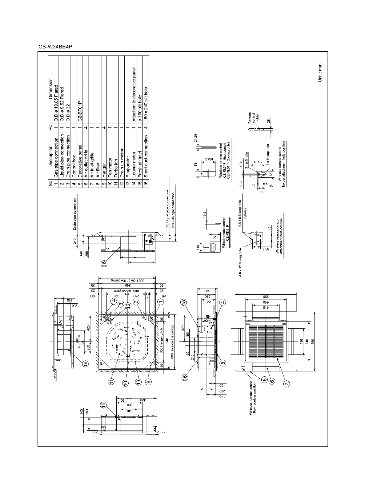
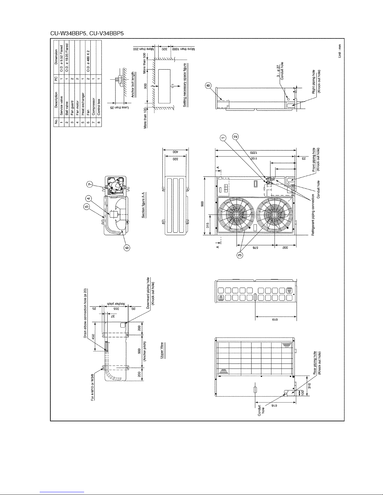
5 TECHNICAL DRAWING
12
13
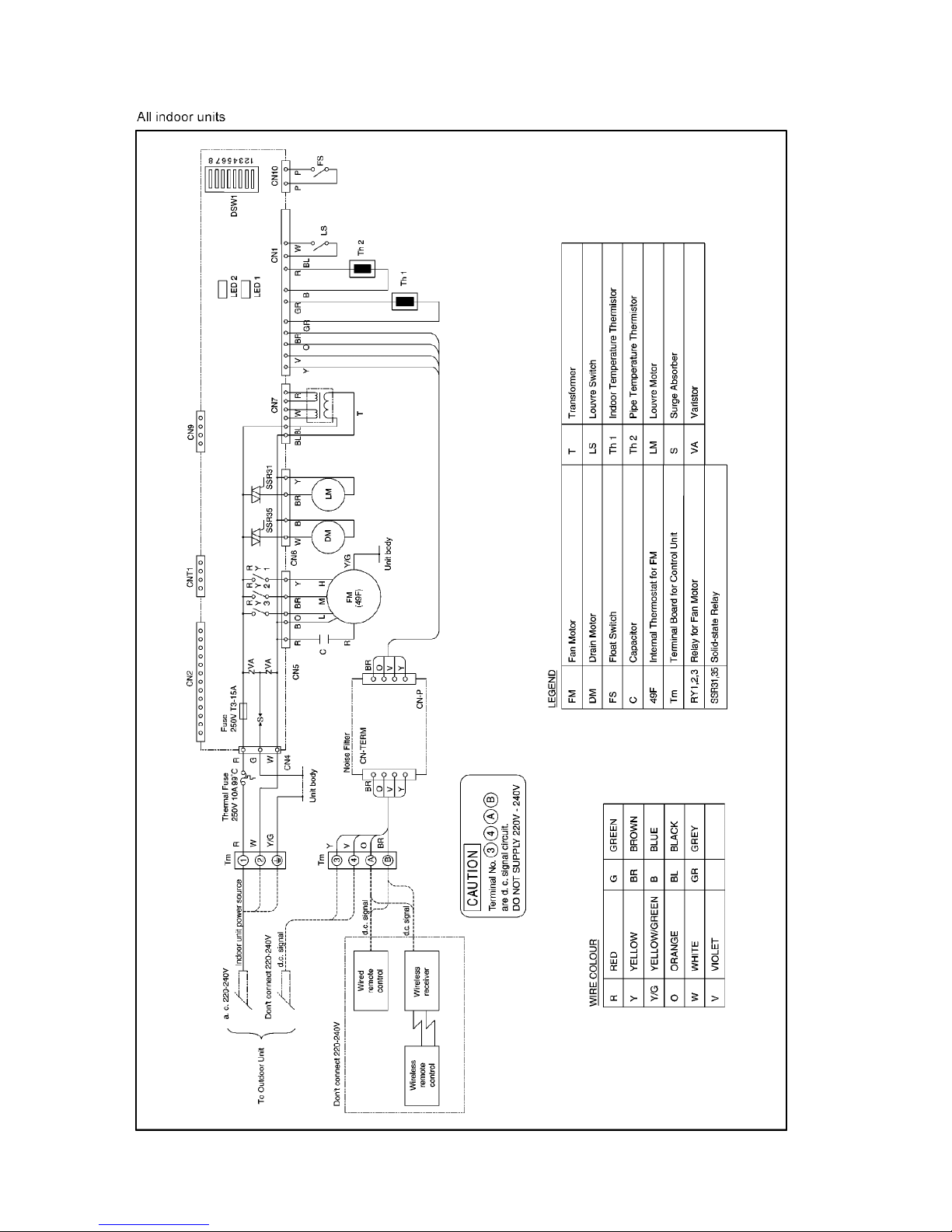
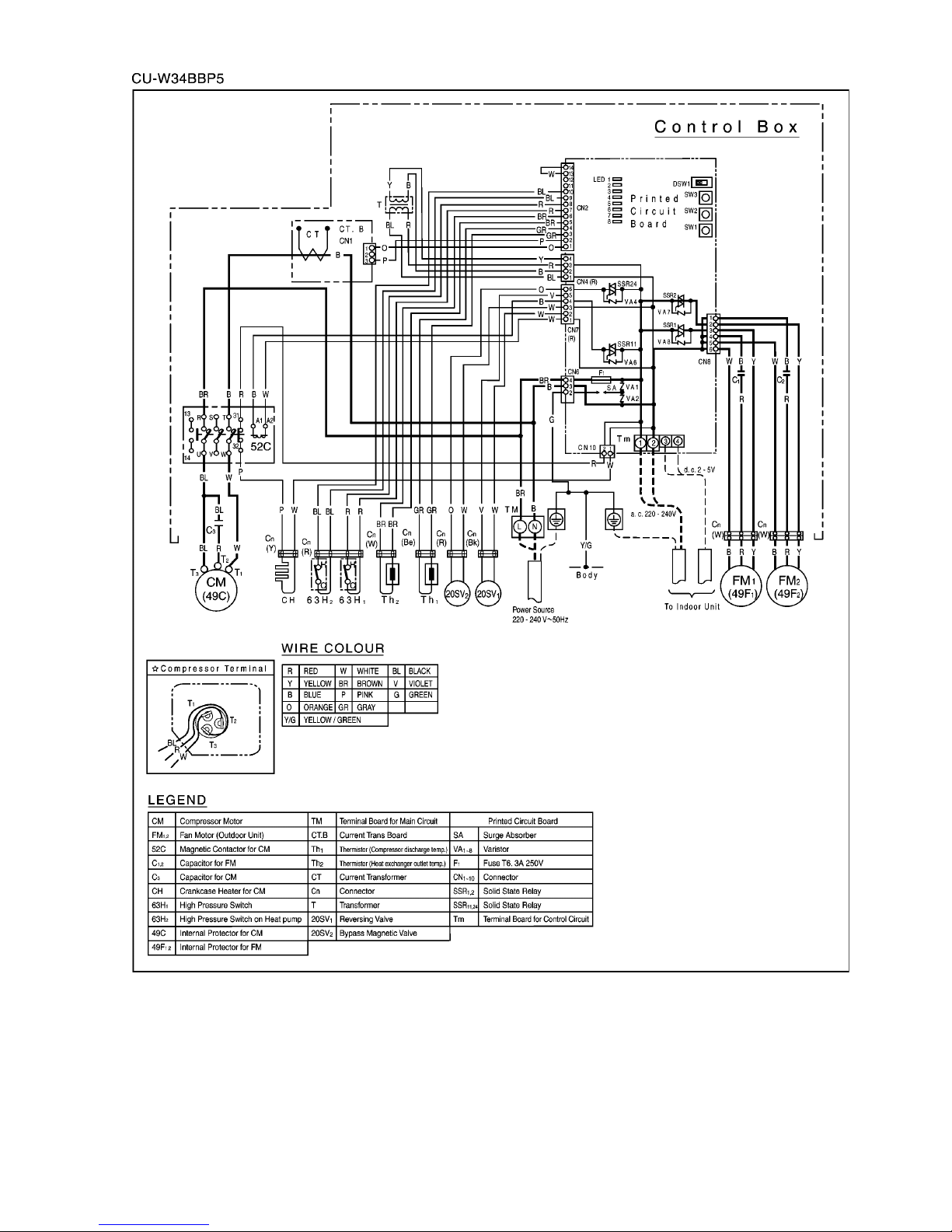
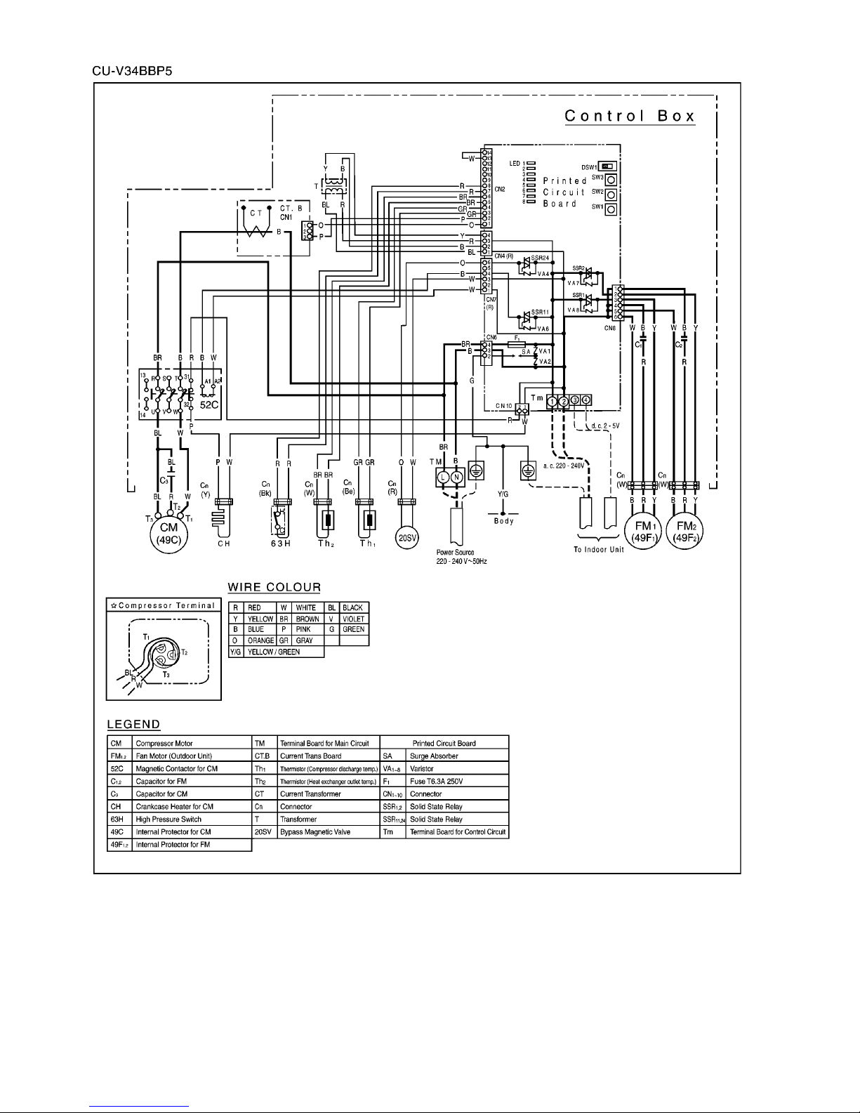
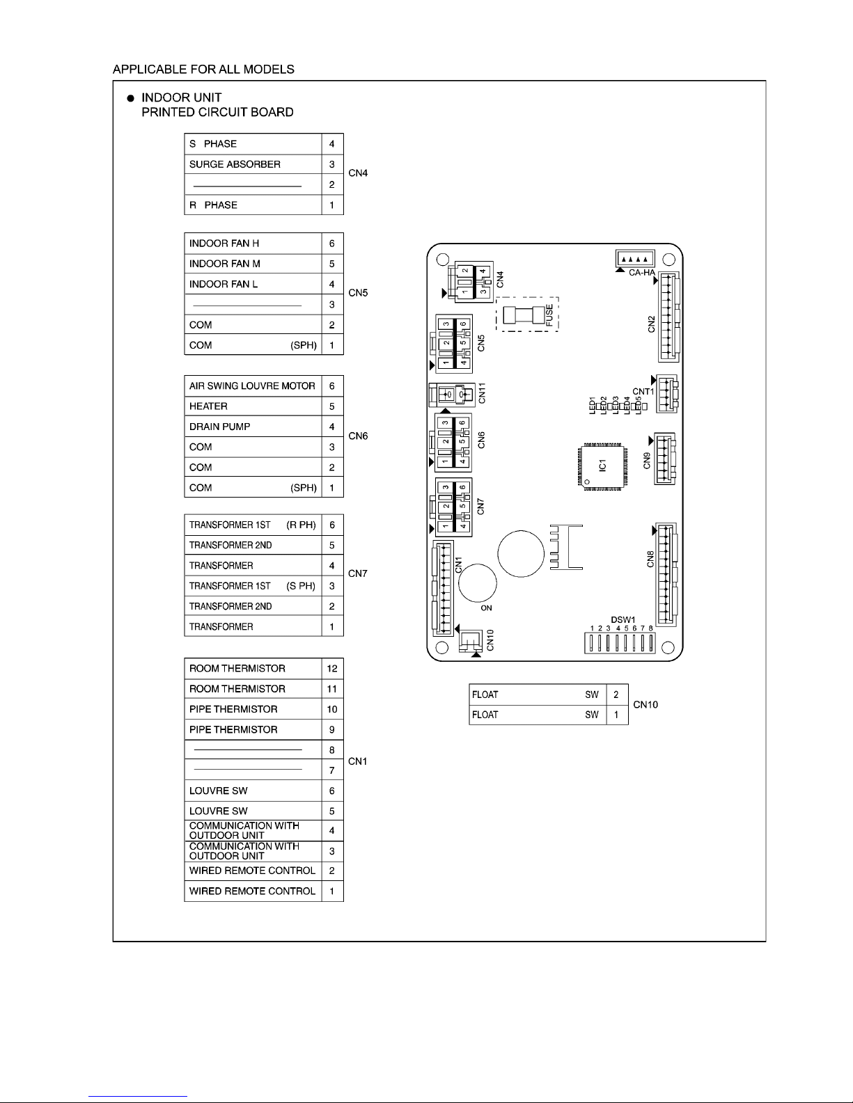
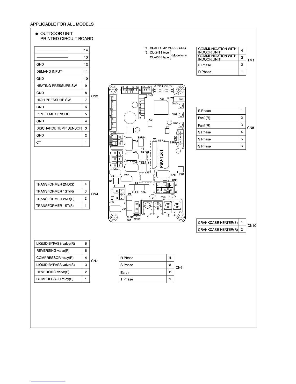
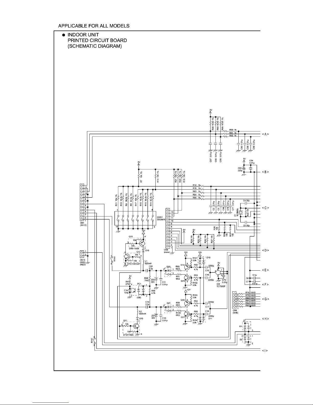
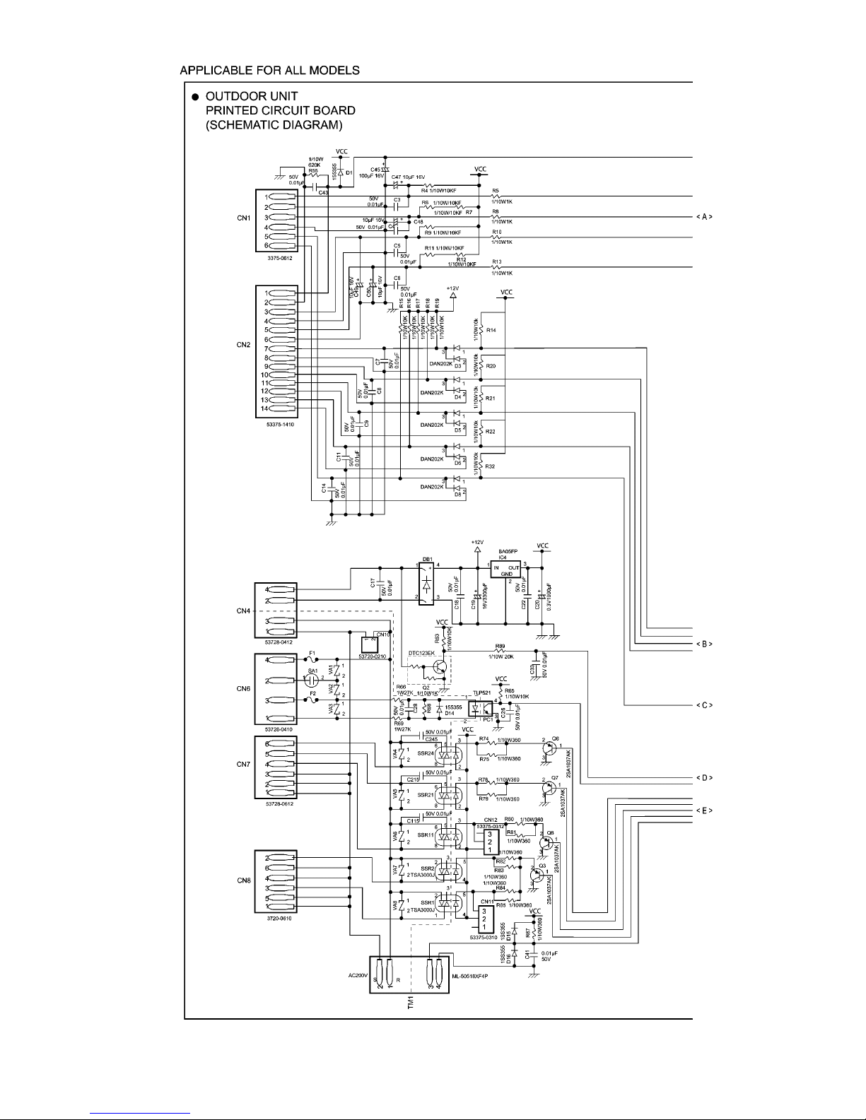
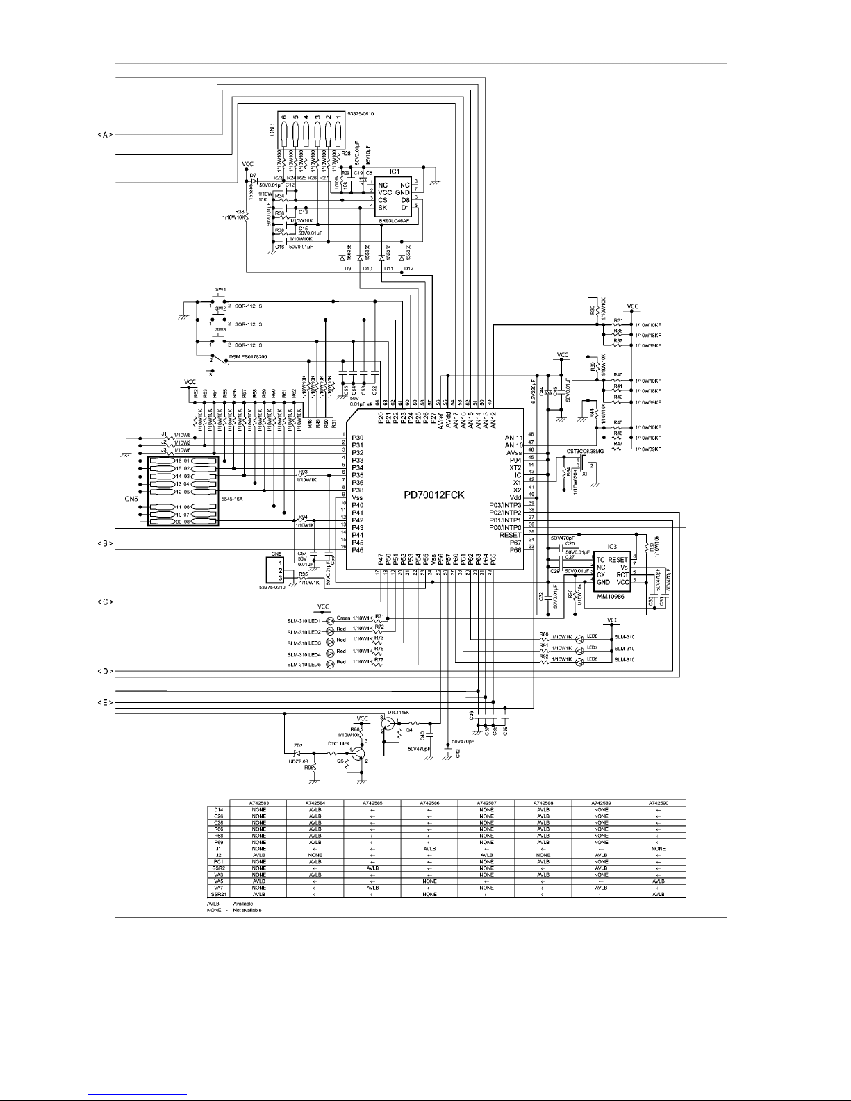
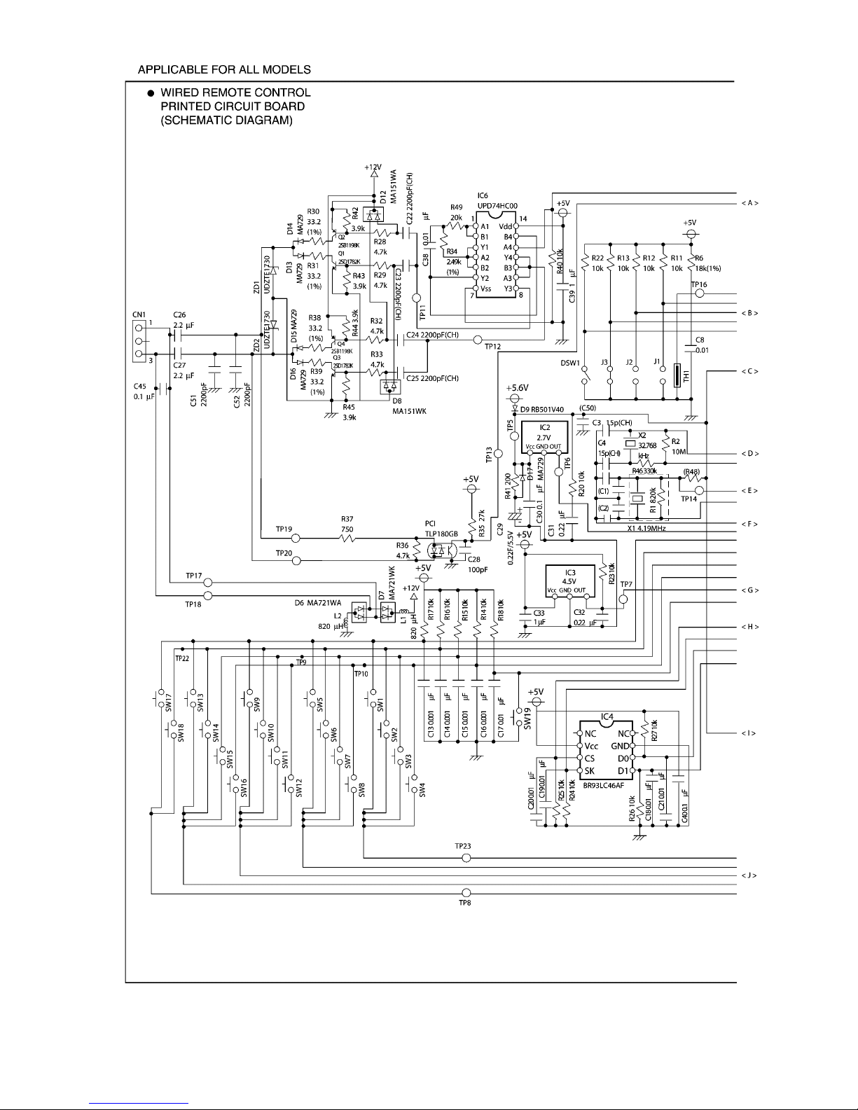
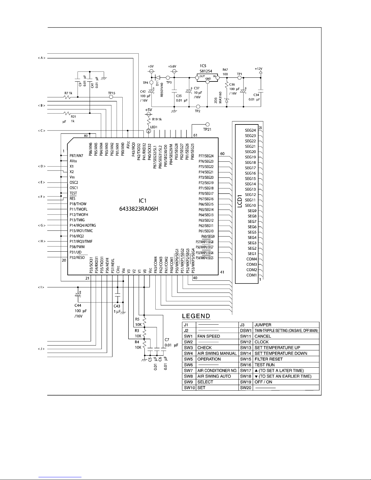
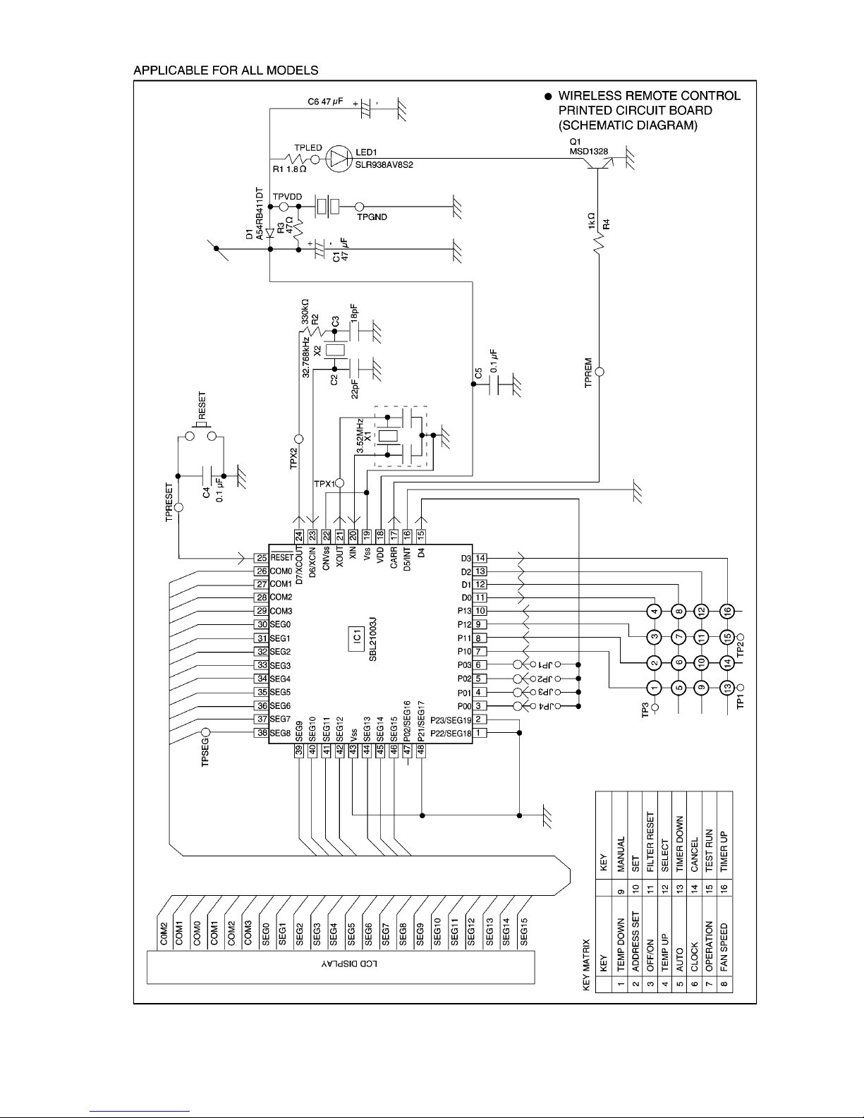
6 CIRCUIT DIAGRAM
14
15
16
17
18
19

20
21
22
23
24
25
7 OPERATING INSTRUCTION
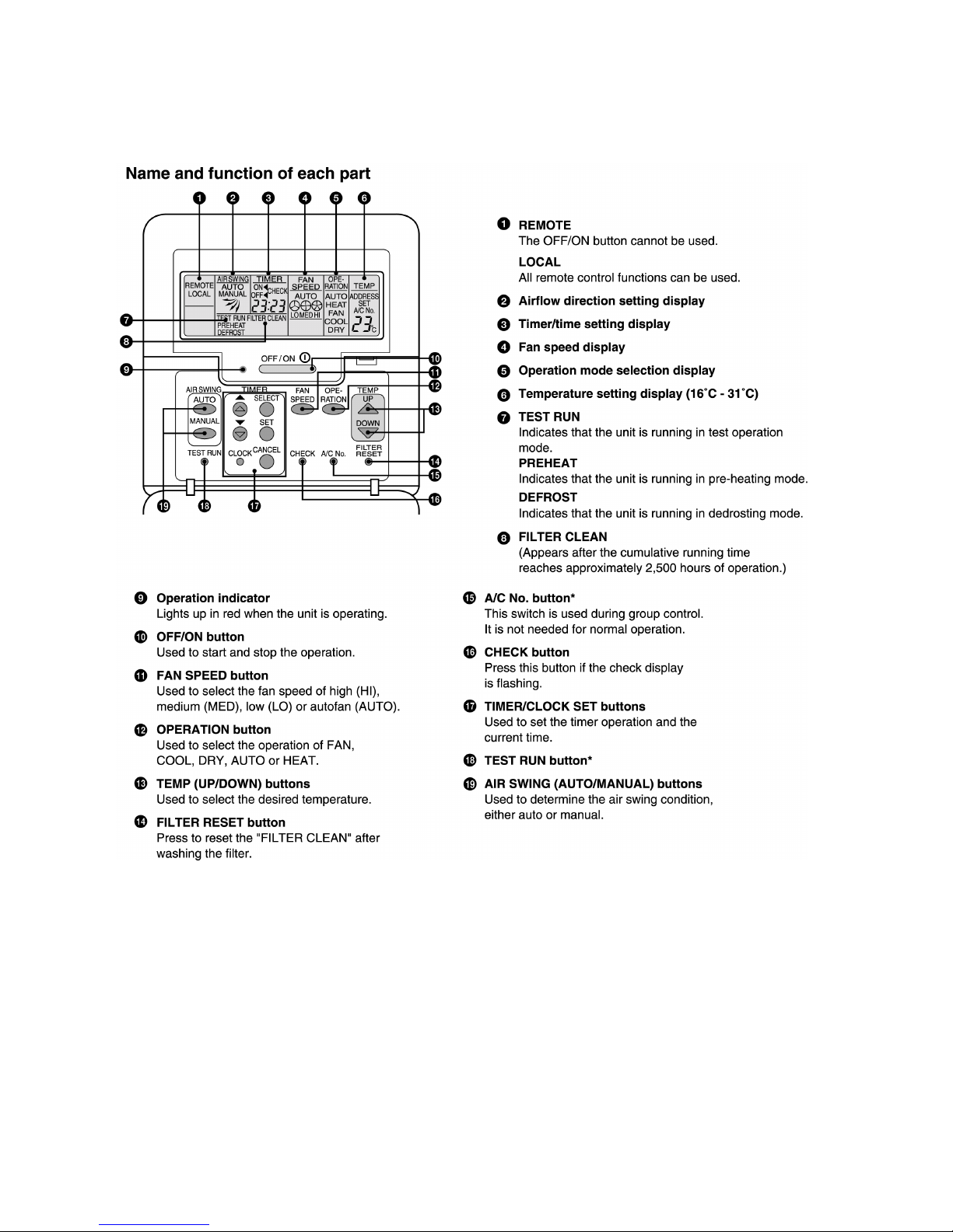
7.1. Wired Remote Control (OPTIONAL PARTS)
NOTES:
•
• •
• Ensure that the correct button is pressed as simultaneous pressing of the multiple buttons will not make the setting correct.
•
• •
• The illustration above is for explanatory purposes only. The appearance will be different during actual operation.
•
• •
• Do not operate the remote control with wet hands. Otherwise, electric shock or malfunction may occur.
•
• •
• Do not press the remote control buttons with sharp object as this may damage the remote control.
•
• •
• Buttons marked with * are not needed for normal operation. If one of these buttons is pressed by mistake, press the same
button once more to cancel the operation.
•
• •
• When the power resumed after power failure, the unit will restart automatically with all the previous settings preserved by the
memory function. (Auto restart function)
26
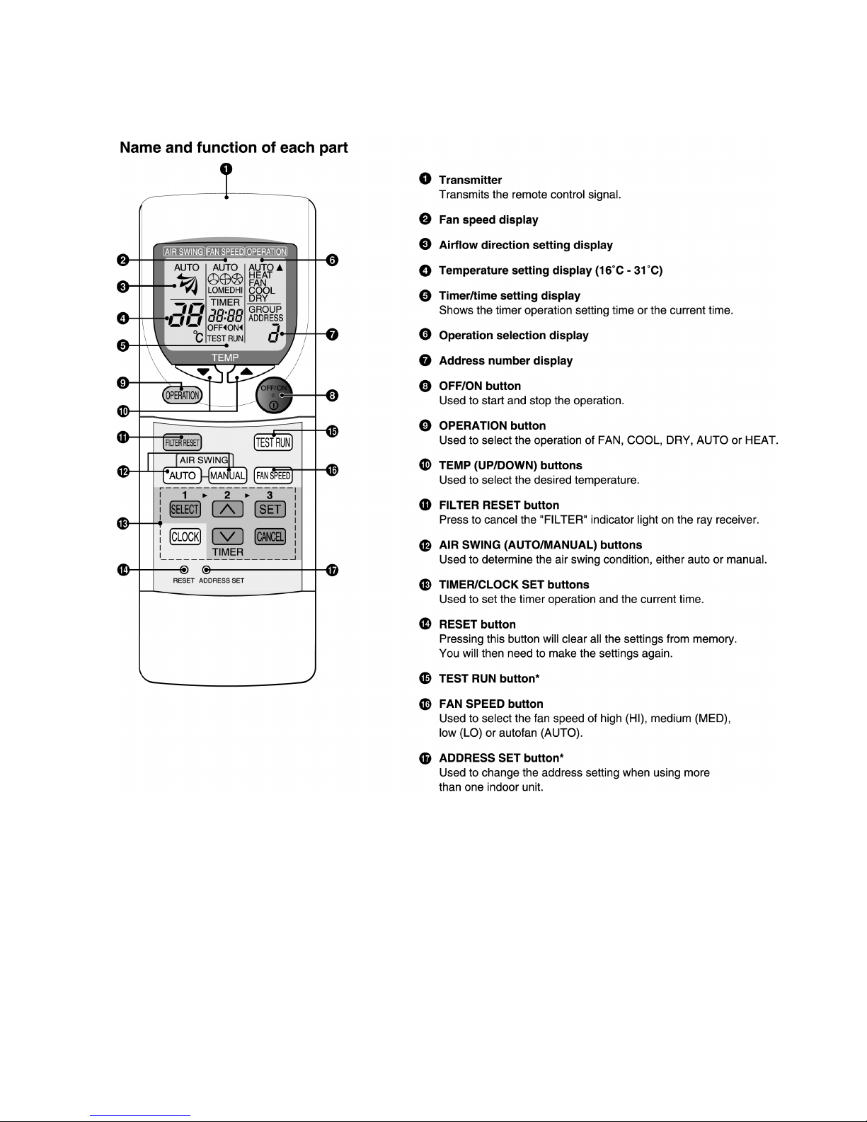
7.2. Wireless Remote Control (OPTIONAL PARTS)
NOTES:
•
• •
• Ensure that the correct button is pressed as simultaneous pressing of the multiple buttons will not make the setting correct.
•
• •
• The illustration above is for explanatory purpose only. The appearance will be different during actual operation.
•
• •
• If using the wireless remote control in conjunction with the wired remote control, the settings made from the wireless remote
control will appear on the wired remote control display (except when making timer settings).
•
• •
• Buttons marked with * are not needed for normal operation. If one of these buttons is pressed by mistake, press the same
button once more to cancel the operation.
•
• •
• When the power resumed after power failure, the unit will restart automatically with all previous settings preserved by the
memory function. (Auto restart function)
27
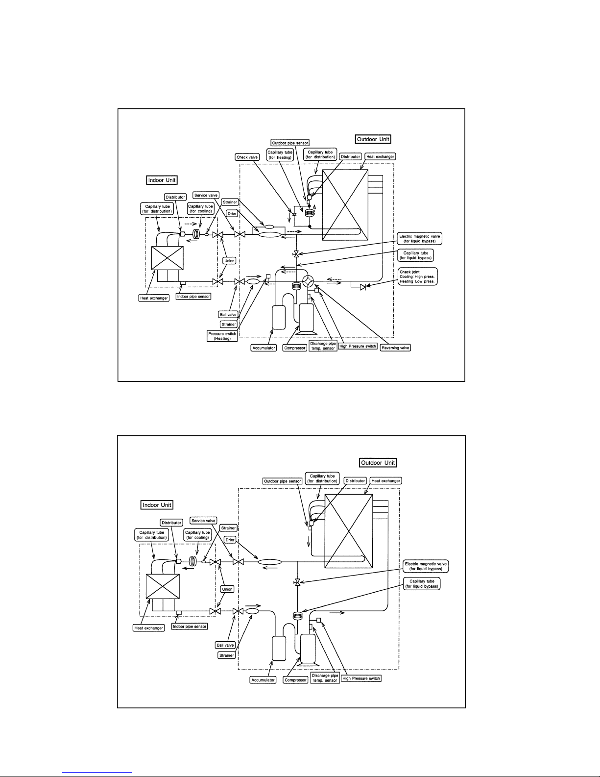
8 REFRIGERATION CYCLE
8.1. Heating Model
CS-W34BB4P / CU-W34BBP5
8.2. Cooling Only Model
CS-W34BB4P / CU-V34BBP5
28
9 OPERATION RANGE
Power Supply
The applicable voltage range for each unit is given in the following table. The working voltage among the three phases must be
balanced within a 3% deviation from each voltage at the compressor terminals. The starting voltage must be higher than 85% of
the rated voltage.
Power Supply
MODEL
Unit Main Power Applicable Voltage
Phase, Volts Hz Max Min
CU-W/V34BBP5 1~220 50 242 198
1~230 50 253 207
1~240 50 264 216
Indoor and Outdoor Temperature
•
• •
• Cooling only type
Model (50Hz) V34BBP5
Operating Hz Indoor Temp. (D.B./W.B.) (°C) Outdoor Temp. (D.B./W.B.) (°C)
Max Min Max Min
Cooling 50 32/23 21/15 43/- -5/-
•
• •
• Heat pump type
Model (50Hz) W34BBP5
Operating Hz Indoor Temp. (D.B./W.B.) (°C) Outdoor Temp. (D.B./W.B.) (°C)
Max Min Max Min
Cooling 50 32/23 21/15 43/- -5/Heating 50 27/- 16/- 24/18 -10/-
29
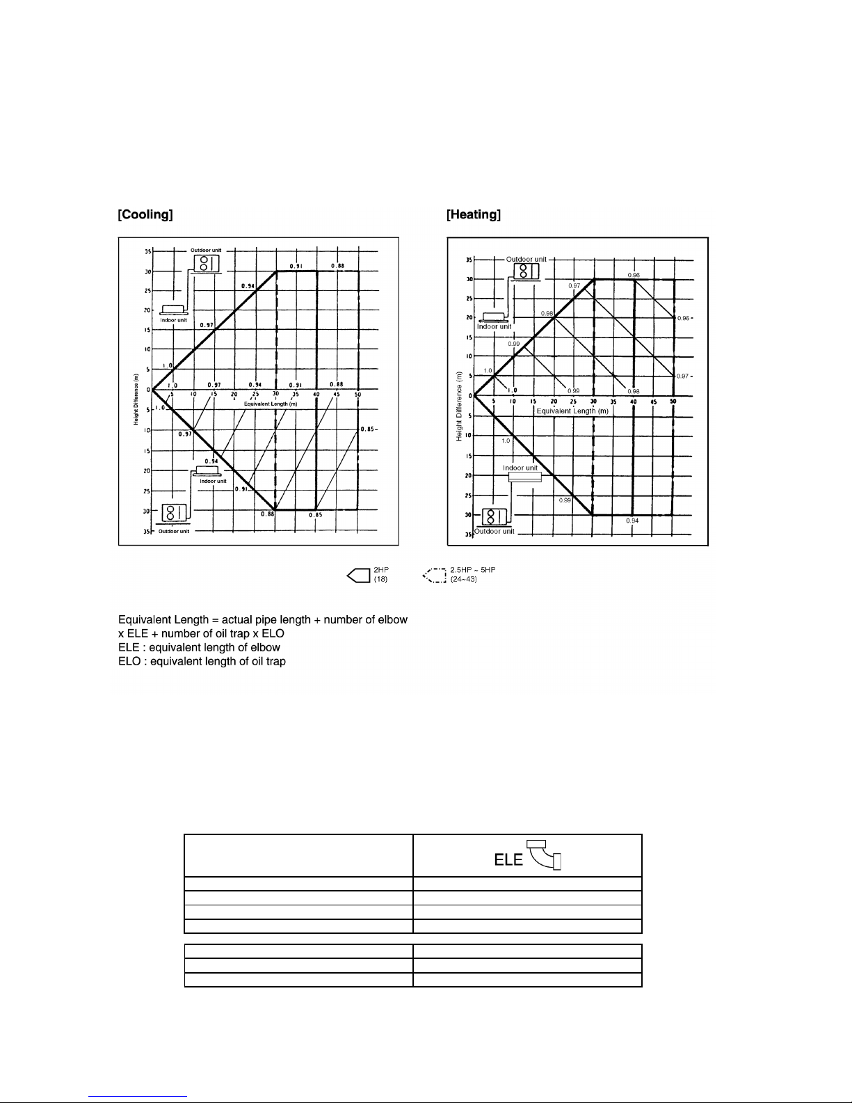
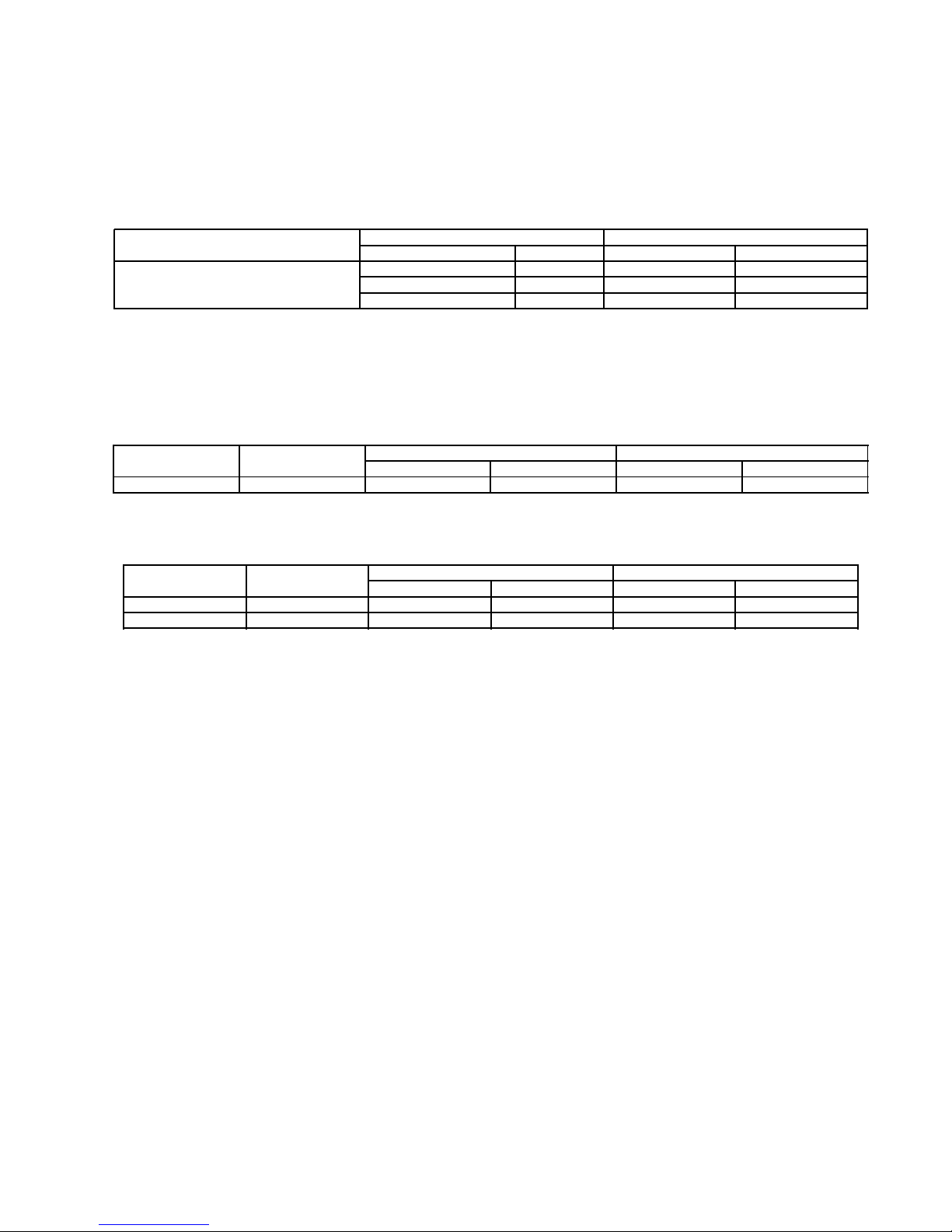
10 PIPE LENGTH
■■■■
CORRECTION OF COOLING CAPACITY AND HEATING CAPACITIES
Correction of cooling and heating capacities according to the connecting pipe length.
The data of cooling capacities (marked on the name plate) are based on 5 meters connecting pipe and horizontal installation.
For other pipe length of other installation multiply by the following correction factor to determine the revised cooling capacity.
■■■■
REFRIGERANT ADDITIONAL CHARGE
•
• •
•
The piping length exceeds 30 metres.
APPLICABLE FOR ALL MODELS
Before shipment, this air conditioner is filled with the rated amount of refrigerant subject to 30m piping length. (The rated
amount of refrigerant is indicated on the name plate.) But when the piping length exceeds 30m, additional charge is required
according to the following table.
Outer diameter of gas side pipe mm (inch)
9.52 (3/8) 0.18
12.7 (1/2) 0.20
15.88 (5/8) 0.25
19.05 (3/4) 0.35
Model Ref. Charge
2.0~2.5HP 20g per 1m
3~5HP 50g per 1m
30
 Loading...