

Panasonic cs-me5d3ua, cs-me7sd3ua installation
Install
Indoor Unit
CS-ME5SD3UA
CS-ME7SD3UA
Destination
USA
Please file and use this manual together with the service manual for Model No. CU-2E18SBU, Order No. PAPAMY1604017CE.
WARNING
This service information is designed for experienced repair technicians only and is not designed for use by the general public.
It does not contain warnings or cautions to advise non-technical individuals of potential dangers in attempting to service a product.
Products powered by electricity should be serviced or repaired only by experienced professional technicians. Any attempt to service
or repair the product or products dealt with in this service information by anyone else could result in serious injury or death.
PRECAUTION OF LOW TEMPERATURE
In order to avoid frostbite, be assured of no refrigerant leakage during the installation or repairing of refrigerant circuit.
© Panasonic Corporation 2016
11. Installation Instruction
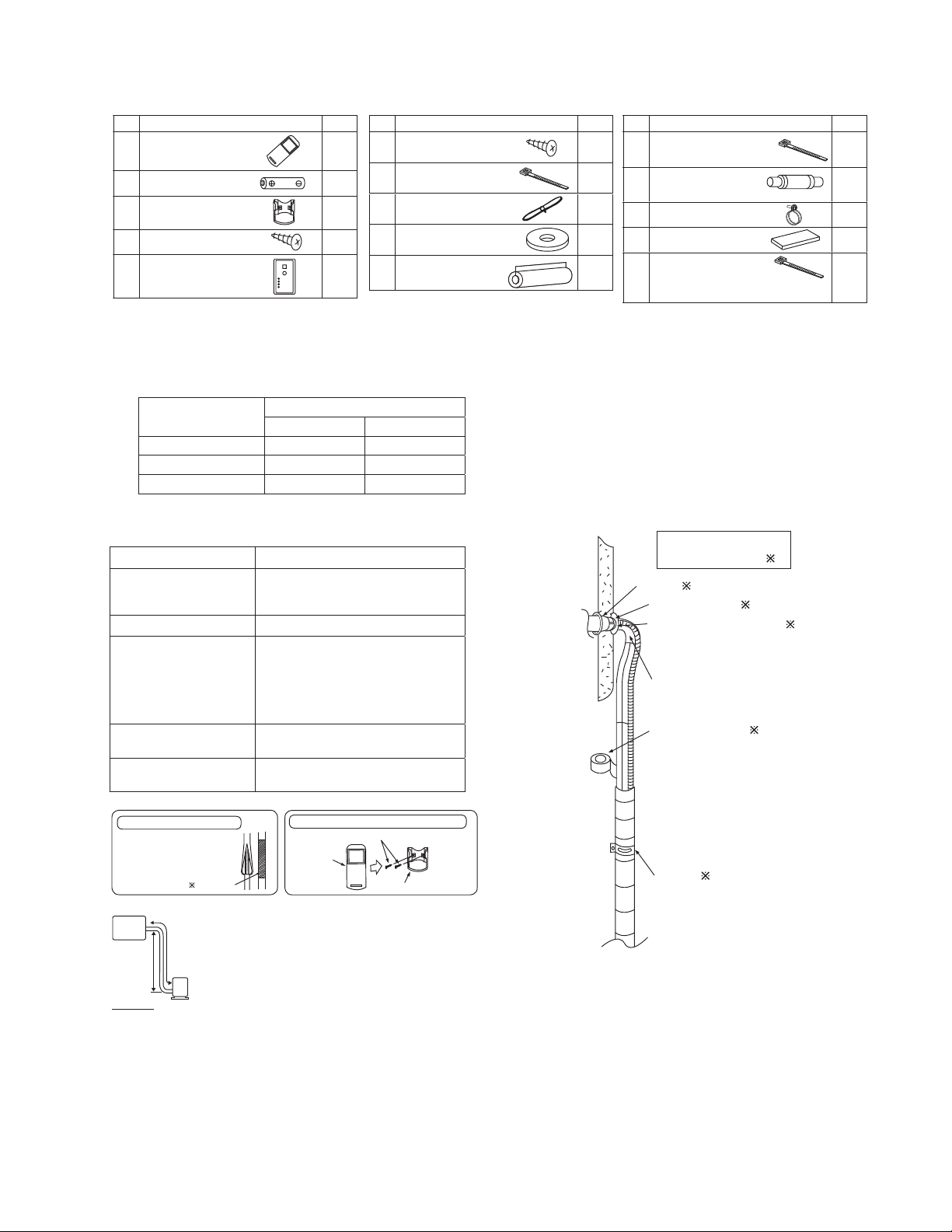
Attached Accessories
No. Accessory part Qty.
Remote control
1
Battery
2
Remote control holder
3
Remote control holder
4
fi xing screw
Remote control receiver
5
Ŷ
Required Materials
x Read the catalog and other technical materials and prepare the required materials.
x Applicable piping kit
Applicable piping kit
CZ-3F5, 7BP 3/8" (9.52 mm) 1/4" (6.35 mm)
CZ-4F5, 7, 10BP 1/2" (12.7 mm) 1/4" (6.35 mm)
CZ-52F5, 7, 10BP 5/8" (15.88 mm) 1/4" (6.35 mm)
Gas Liquid
Ŷ
Other Items to be Prepared (Locally Purchased)
Product name Remarks
Rigid PVC pipe
Adhesive PVC adhesive
Insulation
Indoor/outdoor connecting
cable
Hanging bolt related parts
VP20 (outer diameter ø1 1/32" (ø26);
also sockets, elbows and other parts
as necessary
For refrigerant piping insulation:
foamed polyethylene with a thickness
of 5/16" (8 mm) or more.
For drain piping insulation:
foamed polyethylene with a thickness
of 13/32" (10 mm) or more.
UL listed or CSA approved 4
conductor wires minimum AWG16
Hanging bolts (M10) (4) and nuts (12),
(when hanging the indoor unit)
Insulation of piping connections
• Carry out insulation after
checking for gas leaks and
secure with vinyl tape.
Vinyl tape
Indoor unit
Attaching the remote control holder to the wall
Remote control holder fi xing screws
Remote
1
control
No. Accessory part Qty.
Receiver fi xing screw
(M4 x 39/64" (15.5 mm))
6
1
Clamper (band)
7
2
1
2
1
Piping size
(for receiver cable fi xing)
Receiver cable
8
(6.56 ft (2 m))
Washer
9
(for suspension fi tting)
Flare insulator
(for gas pipe / liquid pipe
0
connection)
4
Remote control holder
3
No. Accessory part Qty.
Clamper (band)
2
1
1
8
2
(for fl are & drain insulating
!
connection)
Drain hose
(for unit & PVC pipe
@
connection)
Hose band
#
(for drain hose connection)
Drain hose insulation
$
(for drain pipe connection)
Clamper (band)
(for power supply cord)
%
* Be sure to fi x the power supply cord
with clamper (band).
Installation parts you
should purchase (
Sleeve (
Bushing-Sleeve (
Putty (Gum Type Sealer) (
Bend the pipe as closely on
the wall as possible, but be
careful that it doesn’t break.
Vinyl tape (Wide) (
• Apply after carrying
out a drainage test.
• To carry out the
drainage test,
remove the air fi lters
and pour water into
the heat exchanger.
Saddle (
4
L=131
1
1
2
1
)
)
)
)
)
)
A
B
Outdoor
unit
IMPORTANT
Begin the installation job from
the “Indoor Unit” installation.
It is advisable to avoid more than 2 blockage
directions. For better ventilation & multiple-outdoor
installation, please consult authorized dealer/specialist.
x This illustration is for explanation purposes only.
The indoor unit will actually face a different way.
x Respective outdoor unit installation procedure
shall refer to instruction manual provided in the
outdoor unit packaging.
17

11.1 Indoor Unit
11.1.1 Selecting the Installation Location
Take into consideration the following contents when creating the blueprint.
Ŷ
Indoor unit installation location
x Do not install the unit in excessive oil fume area such as kitchen, workshop and etc.
x The location should be strong enough to support the main unit without vibration.
x There should not be any heat or steam source nearby.
x Drainage should be easy. Avoid locating the drain port close to ditches (domestic wastewater).
x Avoid locations above entrances and exits.
x Do not block the air intake and discharge passages.
x Select the location that enables the cool and warm air to spread out to the entire room.
x Locate the indoor unit at least 3.28 ft (1 m) or more away from a TV, radio, wireless appliance, antenna cable and
fluorescent light, and 6.56 ft (2 m) or more away from a telephone.
x Recommended installation height for indoor unit shall be at least 8.27 ft (2.5 m) from floor.
11.1.2 To Drill a Hole in the Wall and Install a Sleeve of Piping
1 Insert the piping sleeve to the hole.
2 Fix the bushing to the sleeve.
3 Cut the sleeve until it extrudes about 19/32"
(15 mm) from the wall.
When the wall is hollow, be sure to use the sleeve for tube
assembly to prevent pests from damaging the cables, e.g.
mice biting the connection cable.
4 Finish by sealing the sleeve with putty or
caulking compound at the final stage.
Indoor
Sleeve
for tube
assembly
3
2
/4
ø
" (ø70 mm)
through hole
Wall
Outdoor
Bushing for
19
(15 mm)
/32"
Putty or caulking compound
tube assembly
Approx.
7
" -
9/32
/32
(5 - 7 mm)
"
11.1.3 Installing the Indoor Unit (Installation Embedded in the Ceiling)
11.1.3.1 Preparation Before Installation
x Always provide sufficient entry and exit space to allow installation work, inspection and unit replacement.
x Waterproof the rear surface of the ceiling below the unit in consideration of water droplets forming and dropping.
When cooling operation is performed for an extended period under the following conditions, water droplets may form and drop. Attach locally
purchased insulation (foamed polyethylene with a thickness of 7/32" (5 mm) or more) to the outside of the indoor unit before installing into the
ceiling to improve heat insulation.
x Locations with a dew point inside the ceiling of 73.4°F (23°C) or more
x Kitchens and other locations that produce large amounts of heat and steam
x Locations where the inside of the ceiling serves as an outside air intake passage
x When installing into a ceiling, select the unit position and airflow direction that enable the cool and warm
air to spread out to the whole room.
x Do not place objects that might obstruct the airflow within 3.28 ft (1 m) below the intake grill.
18
 Loading...