

Panasonic cs-me5rkua, cs-me7rkua service manual
Order No: PAPAMY1503085AE
/
TEMP
O
S
O
123
C
Indoor Unit
CS-ME5RKUA
CS-ME7RKUA
FAN
AUTO
SPEED
HEAT
AIR
COOL
SWING
DRY
FAN
AUTO
OFF/ON
FF/ON
ECONAVI
COMFORT
MODE
TEMP
AIRSWING
POWERFUL/
FANSPEED
QUIET
TIMER
TIMER
ET
ON
SET
123
CANCELONOFF
CANCEL
FF
AC RC
SETCHECK CLOCK RESET
HECK
Destination
USA
Canada
Please file and use this manual together with the service manual for Model No. CU-2E18NBU, CU-5E36QBU and CU-3E19RBU
CU-4E24RBU, Order No. PHAAM1111120A1, PAPAMY1312037CE and PAPAMY1505100CE.
WARNING
This service information is designed for experienced repair technicians only and is not designed for use by the general public.
It does not contain warnings or cautions to advise non-technical individuals of potential dangers in attempting to service a product.
Products powered by electricity should be serviced or repaired only by experienced professional technicians. Any attempt to
service or repair the products dealt with in this service information by anyone else could result in serious injury or death.
In order to avoid frostbite, be assured of no refrigerant leakage during the installation or repairing of refrigerant circuit.
PRECAUTION OF LOW TEMPERATURE
© Panasonic Corporation 2015.

TABLE OF CONTENTS
1. Safety Precautions ............................................. 3
2. Specification ....................................................... 5
3. Features ............................................................... 9
4. Location of Controls and Components .......... 10
4.1 Indoor Unit .................................................. 10
4.2 Outdoor Unit ............................................... 10
4.3 Remote Control .......................................... 10
5. Dimensions ....................................................... 11
5.1 Indoor Unit .................................................. 11
6. Wiring Connection Diagram ............................ 12
6.1 Indoor Unit .................................................. 12
7. Electronic Circuit Diagram .............................. 13
7.1 Indoor Unit .................................................. 13
8. Printed Circuit Board ....................................... 14
8.1 Indoor Unit .................................................. 14
9. Installation Instruction ..................................... 16
9.1 Select the Best Location ............................. 16
9.2 Indoor Unit .................................................. 17
14. Exploded View and Replacement Parts
List .....................................................................71
14.1 Indoor Unit ..................................................71
10. Operation Control ............................................. 21
10.1 Basic Function ............................................ 21
10.2 Cooling operation ....................................... 21
10.3 Soft Dry Operation ...................................... 21
10.4 Heating Operation ...................................... 21
10.5 Automatic Operation ................................... 22
10.6 Indoor Fan Speed Control .......................... 22
10.7 Indoor Fan Motor Operation ....................... 23
10.8 Outdoor Fan Motor Operation .................... 24
10.9 Airflow Direction .......................................... 24
10.10 Quiet Operation (Cooling Mode/Cooling
Area of Dry Mode) ...................................... 25
10.11 Quiet Operation (Heating) .......................... 25
10.12 Powerful Mode Operation ........................... 25
10.13 Timer Control .............................................. 26
10.14 Auto Restart Control ................................... 26
10.15 Indication Panel .......................................... 26
10.16 ECONAVI and AUTO COMFORT
Operation .................................................... 27
11. Servicing Mode ................................................. 30
11.1 Auto Off/On Button ..................................... 30
11.2 Remote Control Button ............................... 31
12. Troubleshooting Guide .................................... 32
12.1 Refrigeration Cycle System ........................ 32
12.2 Breakdown Self Diagnosis Function ........... 34
12.3 Error Code Table ........................................ 35
12.4 Self-diagnosis Method ................................ 37
13. Disassembly and Assembly Instructions ...... 67
13.1 Indoor Electronic Controllers,
Cross Flow Fan and Indoor Fan Motor
Removal Procedures .................................. 67
2
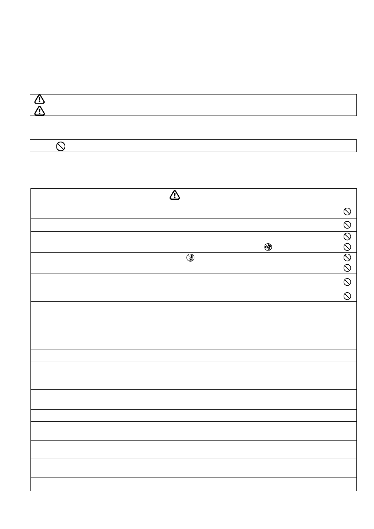
1. Safety Precautions
Read the following “SAFETY PRECAUTIONS” carefully before perform any servicing.
Electrical work must be installed or serviced by a licensed electrician. Be sure to use the correct rating of the
power plug and main circuit for the model installed.
The caution items stated here must be followed because these important contents are related to safety. The
meaning of each indication used is as below. Incorrect installation or servicing due to ignoring of the instruction
will cause harm or damage, and the seriousness is classified by the following indications.
WARNING
CAUTION
The items to be followed are classified by the symbols:
Carry out test run to confirm that no abnormality occurs after the servicing. Then, explain to user the operation,
care and maintenance as stated in instructions. Please remind the customer to keep the operating instructions for
future reference.
Do not install outdoor unit near handrail of veranda. When installing air-conditioner unit on veranda of a high rise building, child may
1.
climb up to outdoor unit and cross over the handrail causing an accident.
Do not use unspecified cord, modified cord, joint cord or extension cord for power supply cord. Do not share the single outlet with
2.
other electrical appliances. Poor contact, poor insulation or over current will cause electrical shock or fire.
3. Do not tie up the power supply cord into a bundle by band. Abnormal temperature rise on power supply cord may happen.
4. Do not insert your fingers or other objects into the unit, high speed rotating fan may cause injury.
5. Do not sit or step on the unit, you may fall down accidentally.
6. Keep plastic bag (packaging material) away from small children, it may cling to nose and mouth and prevent breathing.
When installing or relocating air conditioner, do not let any substance other than the specified refrigerant, eg. air etc mix into
7.
refrigeration cycle (piping). Mixing of air etc. will cause abnormal high pressure in refrigeration cycle and result in explosion, injury
etc.
8. Do not add or replace refrigerant other than specified type. It may cause product damage, burst and injury etc.
For R410A model, use piping, flare nut and tools which is specified for R410A refrigerant. Using of existing (R22) piping, flare nut and tools
may cause abnormally high pressure in the refrigerant cycle (piping), and possibly result in explosion and injury.
9.
Thickness or copper pipes used with R410A must be more than 1/32" (0.8 mm). Never use copper pipes thinner than 1/32" (0.8 mm).
It is desirable that the amount of residual oil is less than 0.0008 oz/ft (40 mg/10 m).
Engage authorized dealer or specialist for installation. If installation done by the user is incorrect, it will cause water leakage, electrical
10.
shock or fire.
11. Install according to this installation instructions strictly. If installation is defective, it will cause water leakage, electrical shock or fire.
Use the attached accessories parts and specified parts for installation. Otherwise, it will cause the set to fall, water leakage, fire or electrical
12.
shock.
Install at a strong and firm location which is able to withstand weight of the set. If the strength is not enough or installation is not properly
13.
done, the set will drop and cause injury.
For installation work, follow all electrical, building, plumbing, local codes, regulations and these installation instructions. If electrical circuit
14.
capacity is not enough or a defect is found in electrical work, it will cause electrical shock or fire.
Do not use spliced wires for indoor / outdoor connection cable. Use the specified indoor / outdoor connection cable, refer to instruction
15.
INDOOR UNIT ELECTRICAL WIRING and connect tightly for indoor connection. Clamp the cable so that no external force will have impact
on the terminal. If connection or fixing is not perfect, it will cause heat-up or fi re at the connection.
Wire routing must be properly arranged so that control board cover is fixed properly. If control board cover is not fixed perfectly, it will cause
16.
fire or electrical shock.
This equipment must installed with an Earth Leakage Circuit Breaker (ELCB) or Ground Fault Current Interrupter (GFCI) or Appliance
17.
Leakage Current Interrupter (ALCI) that has been certified by an NRTL Certified Testing Agency and that is suitable for the voltages and
amperages involved. Otherwise, if may cause electrical shock and fire in case of equipment breakdown.
During installation, install the refrigerant piping properly before running the compressor. Operation of compressor without fixing refrigeration
18.
piping and valves at opened position will cause suck-in of air, abnormal high pressure in refrigeration cycle and result in explosion, injury
etc.
During pump down operation, stop the compressor before removing the refrigeration piping. Removal of refrigeration piping while
19.
compressor is operating and valves are opened will cause suck-in of air, abnormal high pressure in refrigeration cycle and result in
explosion, injury etc.
Tighten the flare nut with torque wrench according to specified method. If the flare nut is over-tightened, after a long period, the flare may
20.
break and cause refrigerant gas leakage.
This indication shows the possibility of causing death or serious injury
This indication shows the possibility of causing injury or damage to properties.
This symbol denotes item that is PROHIBITED from doing.
WARNING
3
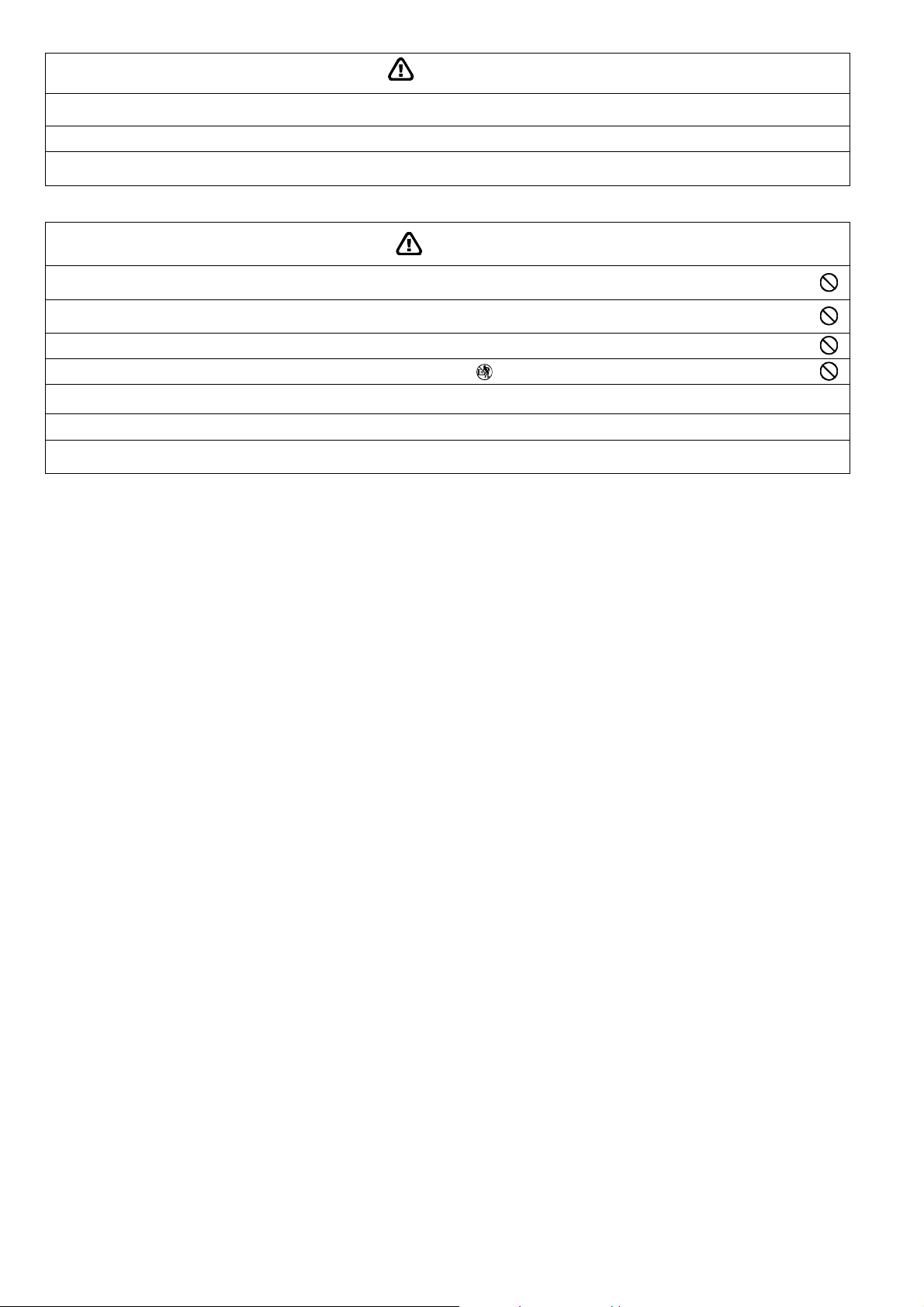
After completion of installation, confirm there is no leakage of refrigerant gas. It may generate toxic gas when the refrigerant contacts with
21.
fire.
22. Ventilate if there is refrigerant gas leakage during operation. It may cause toxic gas when the refrigerant contacts with fire.
This equipment must be properly earthed. Earth line must not be connected to gas pipe, water pipe, earth of lightning rod and telephone.
23.
Otherwise, it may cause electrical shock in case of equipment breakdown or insulation breakdown.
WARNING
CAUTION
Do not install the unit in a place where leakage of flammable gas may occur. In case gas leaks and accumulates at surrounding of
1.
the unit, it may cause fire.
Do not release refrigerant during piping work for installation, re-installation and during repairing refrigeration parts. Take care of the
2.
liquid refrigerant, it may cause frostbite.
3. Do not install this appliance in a laundry room or other location where water may drip from the ceiling, etc.
4. Do not touch the sharp aluminium fin, sharp parts may cause injury.
Carry out drainage piping as mentioned in installation instructions. If drainage is not perfect, water may enter the room and damage the
5.
furniture.
6. Select an installation location which is easy for maintenance.
Installation work.
7.
It may need two people to carry out the installation work.
4
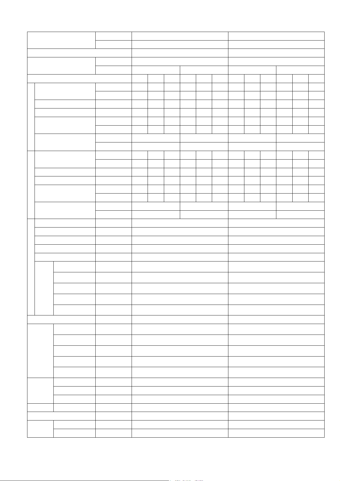
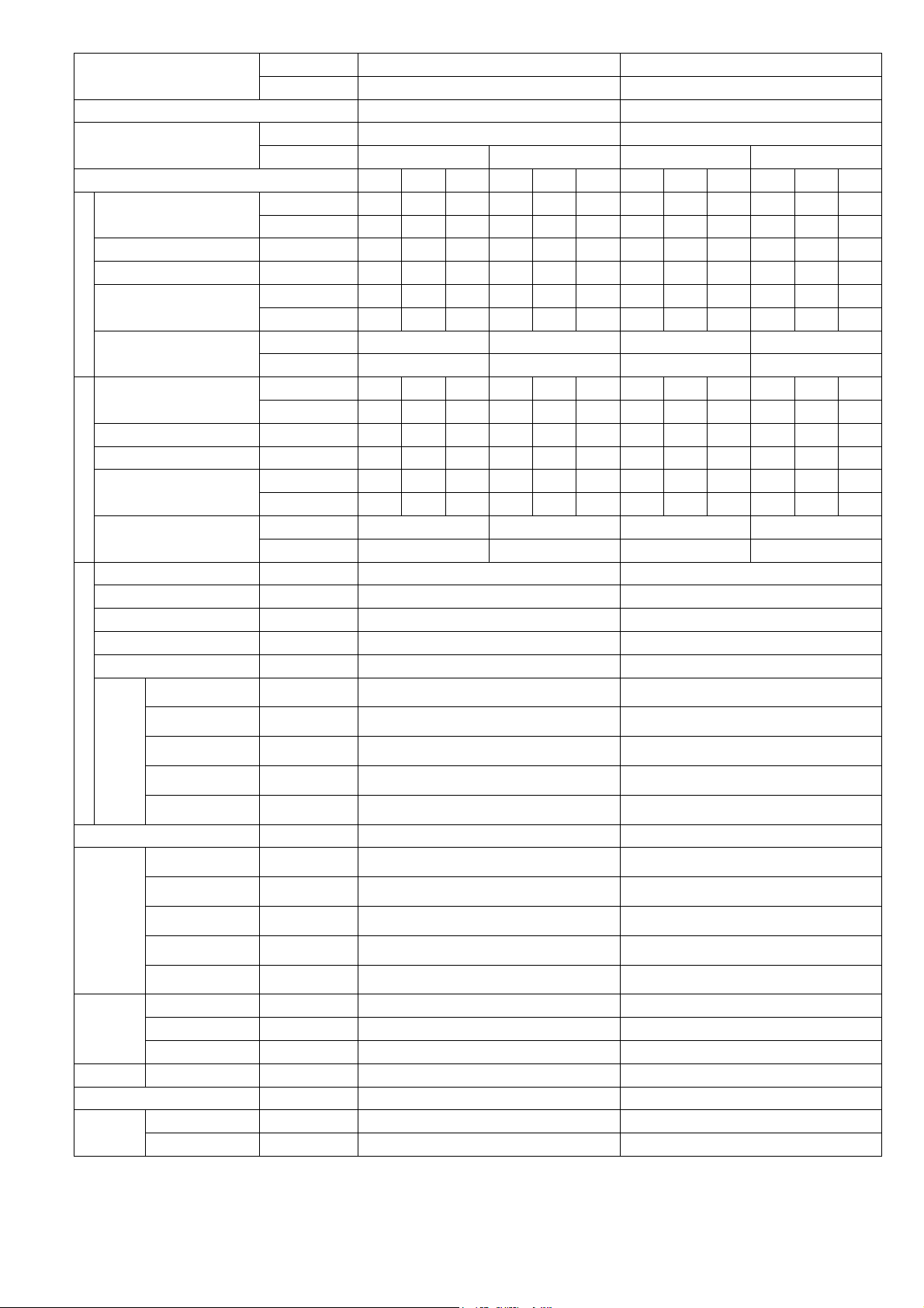
2. Specification
Model
Performance Test Condition AHRI AHRI
Power Supply
Min. Mid. Max. Min. Mid. Max. Min. Mid. Max. Min. Mid. Max.
Capacity
Running Current A - 2.3 - - 2.0 - - 2.8 - - 2.5 -
Input Power W 250 400 640 250 400 640 340 500 810 340 500 810
Cooling
Heating
Indoor Fan
Speed
Moisture Removal L/h (Pt/h) 0.3 (0.6) 0.4 (0.8)
Indoor
Airflow
Dimension
Weight Net (I/D) kg (lb) 9 (20) 9 (20)
Pipe Diameter (Liquid / Gas) mm (inch) 6.35 (1/4) / 9.52 (3/8) 6.35 (1/4) / 9.52 (3/8)
Drain Hose
EER
Indoor Noise (H / L)
Capacity
Running Current A - 3.4 - - 3.0 - - 4.1 - - 3.7 -
Input Power W 300 600 960 300 600 960 300 740 1.23k 300 740 1.23k
COP
Indoor Noise (H / L)
Type Cross-flow fan Cross-flow fan
Material ASG20K1 ASG20K1
Motor Type DC (8 poles) DC (8 poles)
Input Power W 47.0 - 47.0 47.0 - 47.0
Output Power W 40 40
QLo rpm
Lo rpm
Me rpm
Hi rpm
SHi rpm
QLo m
Lo m3/min (ft3/min)
Me m3/min (ft3/min)
Hi m3/min (ft3/min)
SHi m3/min (ft3/min)
Height (I/D) mm (inch) 290 (11-7/16) 290 (11-7/16)
Width (I/D) mm (inch) 870 (34-9/32) 870 (34-9/32)
Depth (I/D) mm (inch) 214 (8-7/16) 214 (8-7/16)
Inner Diameter mm (inch) 16.7 (5/8) 16.7 (5/8)
Length mm (inch) 650 (25-5/8) 650 (25-5/8)
Indoor CS-ME5RKUA CS-ME7RKUA
Outdoor CU-3E19RBU CU-3E19RBU
Phase, Hz Single, 60 Single, 60
V 208 230 208 230
kW 1.30 1.62 2.30 1.30 1.62 2.30 1.80 2.01 2.90 1.80 2.01 2.90
BTU/h 4400 5500 7800 4400 5500 7800 6100 6900 9900 6100 6900 9900
W/W 5.20 4.05 3.59 5.20 4.05 5.20 5.29 4.02 3.58 5.29 4.02 3.58
Btu/hW 17.60 13.75 12.20 17.60 13.75 12.20 17.95 13.80 12.20 17.95 13.80 12.20
dB-A 38 / 25 38 / 25 39 / 25 39 / 25
Power Level dB 54 / - 54 / - 55 / - 55 / -
kW 1.20 2.61 3.20 1.20 2.61 3.20 1.20 3.21 4.10 1.20 3.21 4.10
BTU/h 4100 8900 10900 4100 8900 10900 4100 10900 14000 4100 10900 14000
W/W 4.00 4.35 3.33 4.00 4.35 3.33 4.00 4.34 3.33 4.00 4.34 3.33
Btu/hW 13.65 14.85 11.35 13.65 14.85 11.35 13.65 14.75 11.40 13.65 14.75 11.40
dB-A 40 / 29 40 / 29 41 / 29 41 / 29
Power Level dB 56 / - 56 / - 57 / - 57 / -
3
/min (ft3/min)
Cooling : 570
Heating : 690
Cooling : 660
Heating : 780
Cooling : 820
Heating : 950
Cooling : 990
Heating : 1120
Cooling : 1080
Heating : 1210
Cooling : 6.00 (212)
Heating : 6.88 (243)
Cooling : 7.00 (247)
Heating : 7.89 (279)
Cooling : 8.80 (311)
Heating : 9.79 (346)
Cooling : 10.70 (380)
Heating : 11.70 (415)
Cooling : 11.71 (413)
Heating : 12.70 (448)
Cooling : 570
Heating : 690
Cooling : 660
Heating : 780
Cooling : 840
Heating : 960
Cooling : 1020
Heating : 1150
Cooling : 1100
Heating : 1240
Cooling : 6.06 (214)
Heating : 6.95 (245)
Cooling : 7.06 (249)
Heating : 7.96 (281)
Cooling : 9.08 (321)
Heating : 9.97 (352)
Cooling : 11.10 (390)
Heating : 12.10 (425)
Cooling : 12.10 (425)
Heating : 13.11 (463)
5

Model
Fin Material Aluminium (Pre Coat) Aluminium (Pre Coat)
Indoor Heat
Exchanger
Air Filter
Indoor Operation Range
(Cooling) (°F / °C)
Indoor Operation Range
(Heating) (°F / °C)
1. Cooling capacities are based on indoor temperature of 27°C DRY BULB (80.6°F DRY BULB), 19.0°C WET BULB (66°F WET BULB) and
outdoor air temperature of 35°C DRY BULB (95°F DRY BULB), 24°C WET BULB (75.2°F WET BULB)
2. Heating capacities are based on indoor temperature of 20°C Dry Bulb (68°F Dry Bulb) and outdoor air temperature of 7°C Dry Bulb (44.6°F
Dry Bulb), 6°C Wet Bulb (42.8°F Wet Bulb)
3. Specifications are subjected to change without prior notice for further improvement.
Fin Type Slit Fin Slit Fin
Row x Stage x FPI 2 x 15 x 21 2 x 15 x 21
Size (W x H x L) inch 1 x 12-13/32 x 24 1 x 12-13/32 x 24
Material Polypropelene Polypropelene
Type One-touch One-touch
DRY BULB WET BULB DRY BULB WET BULB
Indoor CS-ME5RKUA CS-ME7RKUA
Outdoor CU-3E19RBU CU-3E19RBU
Maximum 89.6 / 32 73.4 / 23 89.6 / 32 73.4 / 23
Minimum 60.8 / 16 51.8 / 11 60.8 / 16 51.8 / 11
Maximum 86.0 / 30 - / - 86.0 / 30 - / -
Minimum 60.8 / 16 - / - 60.8 / 16 - / -
6
Model
Performance Test Condition AHRI AHRI
Power Supply
Min. Mid. Max. Min. Mid. Max. Min. Mid. Max. Min. Mid. Max.
Capacity
Running Current A - 2.8 - - 2.5 - - 2.8 - - 2.5 -
Input Power W 340 500 810 340 500 810 340 500 810 340 500 810
Cooling
Heating
Indoor Fan
Speed
Moisture Removal L/h (Pt/h) 0.4 (0.8) 0.4 (0.8)
Indoor
Airflow
Dimension
Weight Net (I/D) kg (lb) 9 (20) 9 (20)
Pipe Diameter (Liquid / Gas) mm (inch) 6.35 (1/4) / 9.52 (3/8) 6.35 (1/4) / 9.52 (3/8)
Drain Hose
EER
Indoor Noise (H / L)
Capacity
Running Current A - 4.1 - - 3.7 - - 4.1 - - 3.27 -
Input Power W 300 740 1.23k 300 740 1.23k 300 740 1.23k 300 740 1.23k
COP
Indoor Noise (H / L)
Type Cross-flow fan Cross-flow fan
Material ASG20K1 ASG20K1
Motor Type DC (8 poles) DC (8 poles)
Input Power W 47.0 - 47.0 47.0 - 47.0
Output Power W 40 40
QLo rpm
Lo rpm
Me rpm
Hi rpm
SHi rpm
QLo m
Lo m3/min (ft3/min)
Me m3/min (ft3/min)
Hi m3/min (ft3/min)
SHi m3/min (ft3/min)
Height (I/D) mm (inch) 290 (11-7/16) 290 (11-7/16)
Width (I/D) mm (inch) 870 (34-9/32) 870 (34-9/32)
Depth (I/D) mm (inch) 214 (8-7/16) 214 (8-7/16)
Inner Diameter mm (inch) 16.7 (5/8) 16.7 (5/8)
Length mm (inch) 650 (25-5/8) 650 (25-5/8)
Indoor CS-ME7RKUA CS-ME7RKUA
Outdoor CU-2E18NBU CU-5E36QBU
Phase, Hz Single, 60 Single, 60
V 208 230 208 230
kW 1.80 2.01 2.90 1.80 2.01 2.90 1.80 2.01 2.90 1.80 2.01 2.90
BTU/h 6100 6900 9900 6100 6900 4900 6100 6900 9900 6100 6900 9900
W/W 5.29 4.02 3.58 5.29 4.02 3.58 5.29 4.02 3.58 5.29 4.02 3.58
Btu/hW 17.95 13.80 12.20 17.95 13.80 12.20 17.95 13.80 12.20 17.95 13.80 12.20
dB-A 39 / 25 39 / 25 39 / 25 39 / 25
Power Level dB 55 / - 55 / - 55 / - 55 / -
kW 1.20 3.21 4.10 1.20 3.21 4.10 1.20 3.21 4.10 1.20 3.21 4.10
BTU/h 4100 10900 14000 4100 10900 14000 4100 10900 14000 4100 10900 14000
W/W 4.00 4.34 3.33 4.00 4.34 3.33 4.00 4.34 3.33 4.00 4.34 3.33
Btu/hW 13.65 14.75 11.40 13.65 14.75 11.40 13.65 14.75 11.40 13.65 14.75 11.40
dB-A 41 / 29 41 / 29 41 / 29 41 / 29
Power Level dB 57 / - 57 / - 57 / - 57 / -
3
/min (ft3/min)
Cooling : 570
Heating : 690
Cooling : 660
Heating : 780
Cooling : 840
Heating : 960
Cooling : 1020
Heating : 1150
Cooling : 1100
Heating : 1240
Cooling : 6.06 (214)
Heating : 6.95 (245)
Cooling : 7.06 (249)
Heating : 7.96 (281)
Cooling : 9.08 (321)
Heating : 9.97 (352)
Cooling : 11.10 (390)
Heating : 12.10 (425)
Cooling : 12.10 (425)
Heating : 13.11 (463)
7

Model
Fin Material Aluminium (Pre Coat) Aluminium (Pre Coat)
Indoor Heat
Exchanger
Air Filter
Indoor Operation Range
(Cooling) (°F / °C)
Indoor Operation Range
(Heating) (°F / °C)
1. Cooling capacities are based on indoor temperature of 27°C DRY BULB (80.6°F DRY BULB), 19.0°C WET BULB (66°F WET BULB) and
outdoor air temperature of 35°C DRY BULB (95°F DRY BULB), 24°C WET BULB (75.2°F WET BULB)
2. Heating capacities are based on indoor temperature of 20°C Dry Bulb (68°F Dry Bulb) and outdoor air temperature of 7°C Dry Bulb (44.6°F
Dry Bulb), 6°C Wet Bulb (42.8°F Wet Bulb)
3. Specifications are subjected to change without prior notice for further improvement.
Fin Type Slit Fin Slit Fin
Row x Stage x FPI 2 x 15 x 21 2 x 15 x 21
Size (W x H x L) inch 1 x 12-13/32 x 24 1 x 12-13/32 x 24
Material Polypropelene Polypropelene
Type One-touch One-touch
DRY BULB WET BULB DRY BULB WET BULB
Indoor CS-ME7RKUA CS-ME7RKUA
Outdoor CU-2E18NBU CU-5E36QBU
Maximum 89.6 / 32 73.4 / 23 89.6 / 32 73.4 / 23
Minimum 60.8 / 16 51.8 / 11 60.8 / 16 51.8 / 11
Maximum 86.0 / 30 - / - 86.0 / 30 - / -
Minimum 60.8 / 16 - / - 60.8 / 16 - / -
8

3. Features
Inverter Technology
o Wider output power range
o Energy saving
o Quick Cooling
o More precise temperature control
Environment Protection
o Non-ozone depletion substances refrigerant (R410A)
Long Installation Piping
o Long piping up to 82 feet (25 meters) for 1 room, 164 feet (50 meters) for total room
Easy to use remote control
Quality Improvement
o Random auto restart after power failure for safety restart operation
o Gas leakage protection
o Prevent compressor reverse cycle
o Inner protector to protect Compressor
o Noise prevention during soft dry operation
Operation Improvement
o Quiet mode to reduce the indoor unit operating sound
o Powerful mode to reach the desired room temperature quickly
Serviceability Improvement
o Breakdown Self Diagnosis function
9
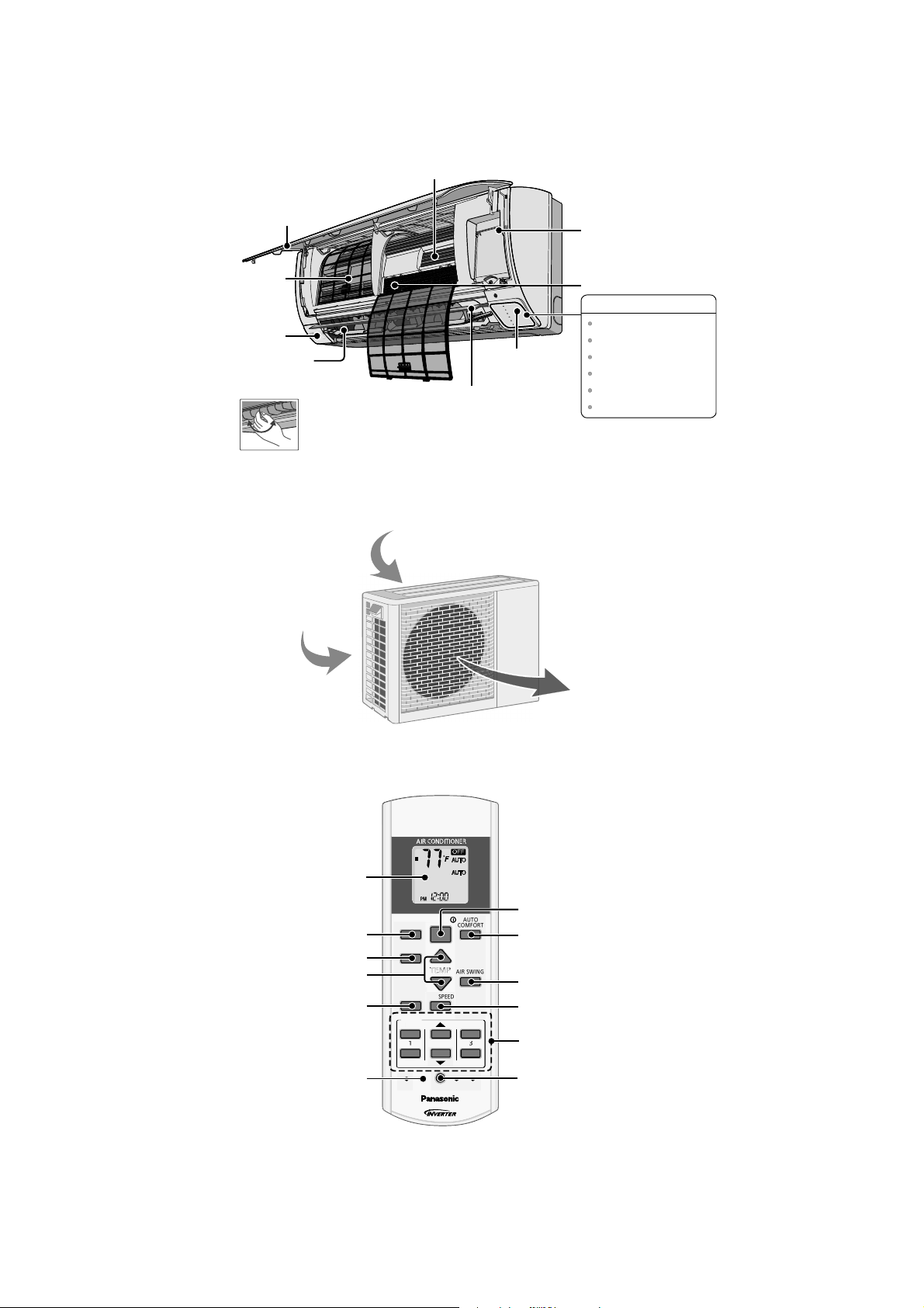
4. Location of Controls and Components
Alu
miniu
mFin
A
TEMP
O
O
N
TIMER
S
CANCEL
O
N
O
2
CHEC
K
4.1 Indoor Unit
Front Panel
Air Filters
Human activity
sensor
Horizontal Airflow
Direction Louver
• Manually adjustable.
4.2 Outdoor Unit
ir inlet (side)
Air inlet (rear)
R
E
W
O
P
R
E
M
I
T
I
V
A
N
O
C
E
T
R
O
F
M
O
C
O
T
U
A
L
U
F
R
E
W
O
P
T
E
I
U
Q
Remote control
receiver and Indicator
Vertical Airflow
Direction Louver
• Do not adjust by hand.
Auto OFF/ON button
Air Purifying Filter
INDICATOR
POWER
TIMER
ECONAVI
AUTO COMFO RT
POWERFUL
QUIET
(Green)
(Orange)
(Green)
(Green)
(Orange)
(Orange)
4.3 Remote Control
Remote control
Econavi operation
Operation mode
Temperature setting
Powerful/Sleep mode
display
operation
Check
AUTO
HEAT
COOL
DRY
FAN
OFF/ON
FF/
ECONAVI
MODE
TEMP
POWERFUL/
FAN SPEED
QUIET
TIMER
ON
1
2
OFF
FF
SET CHECK CLOCK RESET
AUTO
COMFORT
AIR SWING
CANCEL
AC
FAN
SPEED
AIR
SWING
ET
SET
3
RC
Air outlet
OFF/ON
Auto comfort operation
Vertical airflow
direction selection
Fan speed selection
Timer setting
Clock setting
10
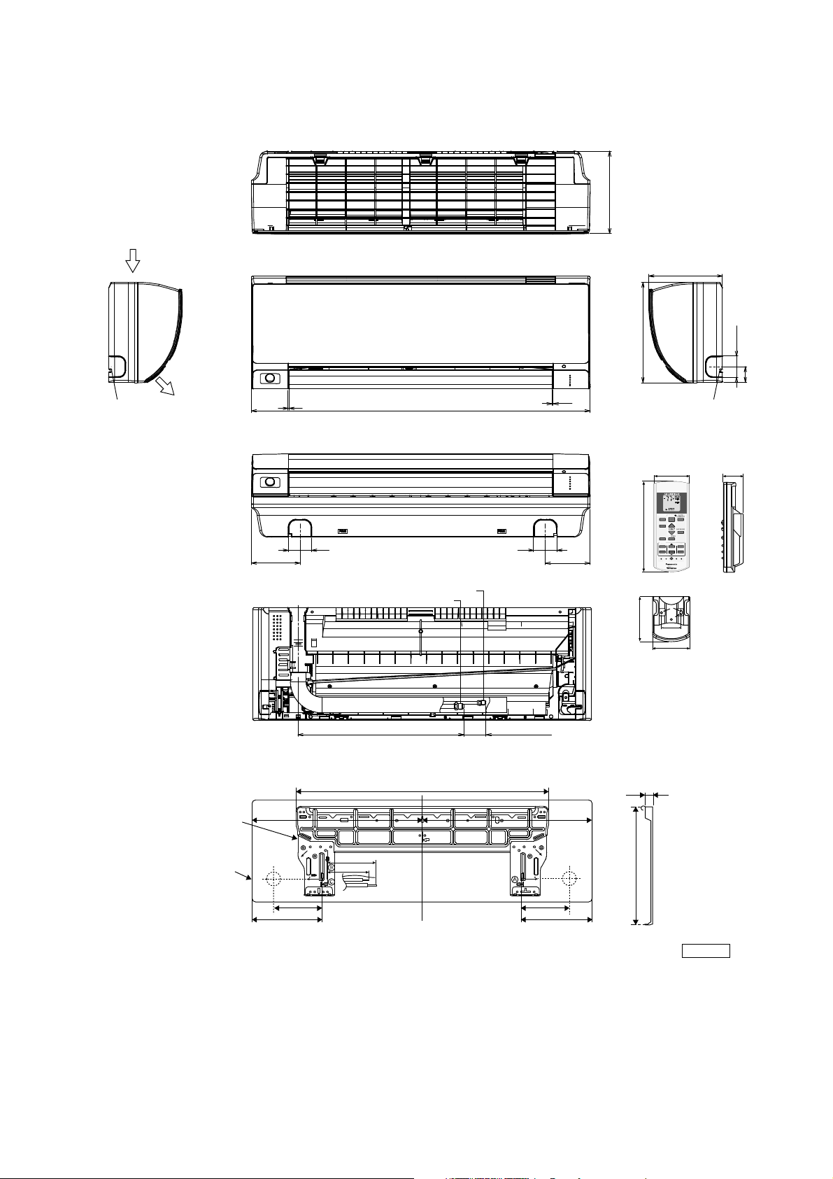
5. Dimensions
/
TEM
O
S
CANC
O
OFF1
3
CHEC
K
5.1 Indoor Unit
<Side View> <Side View>
Air intake
direction
<Top View>
<Front View>
(8-7/16)
8-7/16
Left piping
hole
Air outlet
direction
1/32~1/16
<Bottom View>
4-29/32
<Rear View>
16-1/8
34-9/32
Gas s ide
Liquid si de
2-11/322-11/32
(1-5/8~2-13/32)
1/32~1/16
4-17/32
11- 7/ 16
Right piping
hole
Remote control
1-7/8
FAN
AUTO
SPEED
HEAT
AIR
COOL
SWING
DRY
FAN
AUTO
OFF/ON
FF/ON
ECONAVI
COMFORT
MODE
TEMP
P
AIRSWING
POWERFUL/
QUIET
FANSPEED
5-1/4
TIMER
TIMER
ET
N
SET
3
2
12
EL
CANCELONOFF
AC RC
SETC HECKCLOC K RESET
Remote control holder
2-3/8
2
2-13/32
1-49/64
7/8
Installation
plate
Indoor unit
external
dimensions
line
Relative position between the indoor unit and the installation plate <Front View>
29-29/64
1717-9/32
5-1/16
Right
piping
hole
Left
piping
hole
5-1/16
3-3/4
1-11/16
9-17/32 9-17/32
11
5/8
10-3/8
Unit: inch
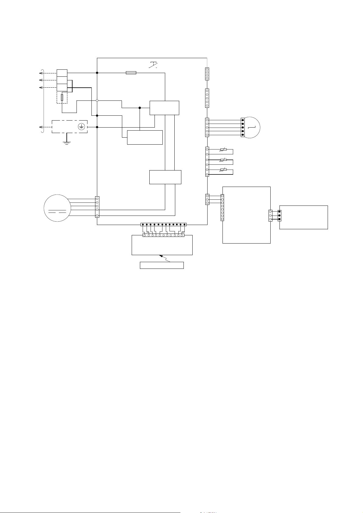
6. Wiring Connection Diagram
6.1 Indoor Unit
TERMINAL
TO
OUTDOOR
UNIT
BOARD
TEMP.
FUSE
102°C
(3A)
GROUNDING
TERMINAL
EVAPORATOR
1
2
3
Y/G
BL
W
R
AC306 (BLK)
AC303 (WHT)
AC304 (RED)
G301 (GRN)
G
FUSE301
T3.15A L250V
COMMUNICATION
CIRCUIT
NOISE FILTER
RECTIFICATION
AUTO SW
(SW01)
CIRCUIT
CIRCUIT
REMARKS
4
(WHT)
1
CN–RMT
5
(WHT)
CN–CNT
1
1
(WHT)
CN–STM1
5
6
(RED)
CN–TH
1
BR
R
O
Y
P
t
t
t
1
5
PIPING TEMP. SENSOR 2
(THERMISTOR)
PIPING TEMP. SENSOR 1
(THERMISTOR)
SUCTION TEM P. SENSOR
(THERMISTOR)
B : BLUE P : PINK
BR : BROWN O : ORANGE
BL : BLAC K Y : YELLOW
W : WHITE G : GREEN
R : RED
Y/G : YELLOW/GREEN
UP DOWN
M
LOUVER MOTOR
FAN MOTOR
M
Y
7
B
6
W
5
BL
4
R
1
CONTROLLER
CN–FM (WHT)
(MAIN)
CN–DISP (YLW)
1
WWWWWWWWW
11
CN–DISP (WHT)
ELECTRONIC CONTROLLER
(DISPLAY & RECEIVER)
REMOTE CONTROLLER
12
1
ELECTRONIC
W
3
1
(WHT)
CN–MSENS
1
W
W
W
1
(WHT)
CN–MSENS
8
CN-SENS1
(COMPARATOR)
ELECTRONIC CONTROLLER
1
3
CN–SENS1
ELECTRONIC
CONTROLLER
(YLW)
(ECO SENSOR)
W
W
(WHT)
3
12
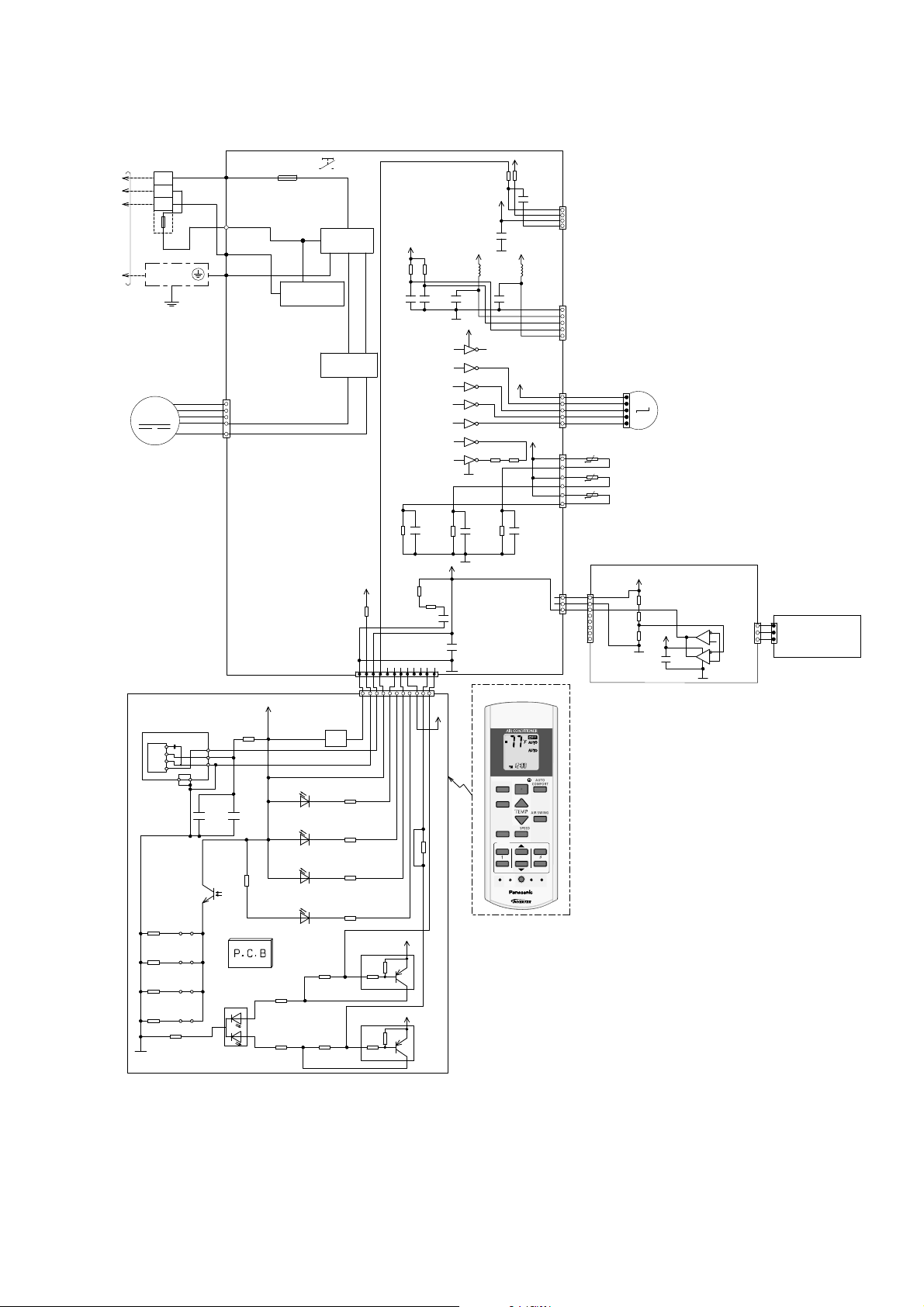
7. Electronic Circuit Diagram
TEMP
OFF/O
N
TIMER
S
CANCEL
O
N
O
2
3
C
T
7.1 Indoor Unit
O
OUTDOOR
UNIT
TERMINAL
BOARD
1
2
3
TEMP.
FUSE
102°C
(3A)
GROUNDING
TERMINAL
Y/G
EVAPORATOR
FAN MOTOR
M
AC306 (BLK)
BL
R
AC303 (WHT)
W
FUSE301
T3.15A L250V
AC304 (RED)
G301 (GRN)
G
COMMUNICATION
7
6
5
4
1
CN–FM ( WHT)
ELECTRONIC
CONTROLLER
(MAIN)
Y
B
W
BL
R
CIRCUIT
AUTO SW
(SW01)
NOISE FILTER
CIRCUIT
RECTIFICATION
CIRCUIT
R62
15.0k
C52
1000p
5V
R90
10k
C25
1u
R82
10k
1000p
C51
20.0k
R61
*R54
270
*C56 *C57
12V
VCC
9
1
16
IC03
2
15
IC03
3
14
IC03
4
13
IC03
5
12
IC03
6
11
IC03
7
10
IC03
GND
8
C27
*R63
1u
5V
*R37
10k
*C45
5V
0.1u
4
1
*C49
CN–RMT
NONE
(WHT)
5V12V
*L5*L6
5
1
CN–CNT
(WHT)
CN–STM1
12V
(WHT)
1
BR
1
R
O
Y
P
5
5V
6
R46R47
1
CN–TH
(RED)
*C28
PIPING TEMP. SENSOR 2
t
(THERMISTOR)
PIPING TEMP. SENSOR 1
t
(THERMISTOR)
SUCTION TEMP. SENSOR
t
(THERMISTOR)
M
5
UP DOWN
LOUVER MOTOR
ELECTRONIC CONTROLLER
(DISPLAY & RECEIVER)
IC201
R213
R208
GND-A
45
JP201R210
JP200R211
JP203R212
JP204
Vout
Vcc
GND
GNDGND
+
C201
47u
c
e
R209
1
2
3
C202
0.01u
R218
0
SEN201
PCB3
LED205
2
POWERFUL/QUIET
(orange/green)
5V_
47
3
1
CN–DISP ( YLW)
CN–DISP (WHT)
POWER
(green)
LED201
TIMER
(orange)
LED202
ECO NAVI
(green)
LED203
NANOE G/AUTO COMF
(green)
LED204
R207
620
R206
2.7k
5V
R89
1
WWWWWWWW W
11
BZ201
BZ
R201 470
R202
2k
R203
27k
R204
820
R216
0
b
4.7k
R217
0
b
4.7k
Q201
10k
Q202
10k
5V
*R74
*R75
*C41
C3
0.1u
CN–MSENS
(WHT)
3
W
W
W
1
12
1
12V
R215
0
5V_
e
c
5V_
e
c
REMOTE CONTR OLLER
DRY
FAN
OFF/ON
ECONAVI
MODE
TEMP
FAN SPEED
QUIET
TIMER
ON
12
FF
OFF
SET CHECK CLOCK RESET
HECK
COMFORT
AIRSWING
CANCEL
AC
FAN
SPEED
AIR
SWING
AUTO
ET
SET
3
RC
AUTO
HEAT
COOL
POWERFUL/
S
M
–
S
E
N
N
C
5V_3
)
H
(
T
W
1
8
ELECTRONIC CONTROLLER
(COMPARATOR)
R401
R402
R403
5V_3
C403
6
7
IC401
5
2
8
1
IC401
3
4
W
1
1
ELECTRONIC
W
W
3
CN–SENS1
CONTROLLER
(YLW)
(ECO SENSOR)
(WHT)
3
CN-SENS1
13
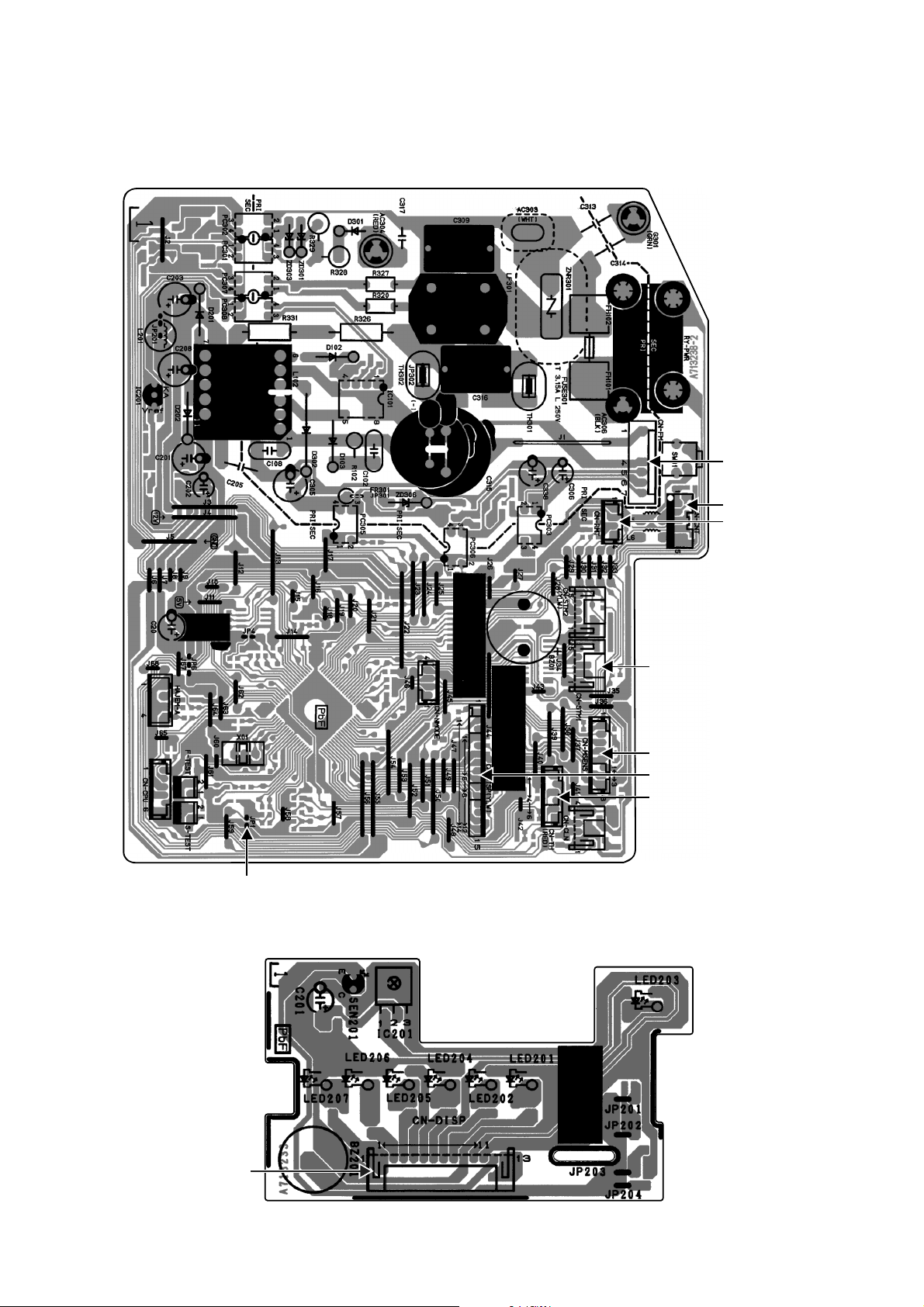
8. Printed Circuit Board
JP1(Ran
dom
R
e
e
nable/d
e
)
8.1 Indoor Unit
8.1.1 Main Printed Circuit Board
CN-FM
CN-CNT
CN-RMT
Auto
start
isabl
8.1.2 Indicator Printed Circuit Board
CN-STM1
CN-MSENS
CN-DISP
CN-TH
CN-DISP
14

8.1.3 Comparator Printed Circuit Board
CN-SENS1
CN-SENS2
CN-MSENS
15
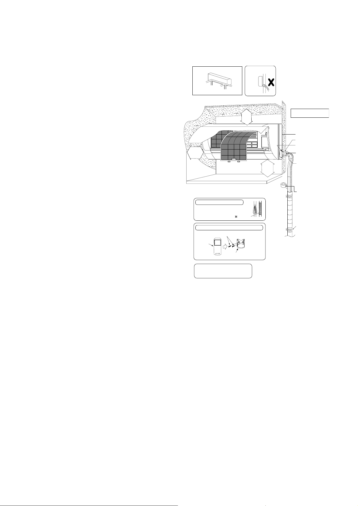
9. Installation Instruction
9.1 Select the Best Location
9.1.1 Indoor Unit
Do not install the unit in excessive oil fume area
such as kitchen, workshop and etc.
There should not be any heat source or steam
near the unit.
There should not be any obstacles blocking the air
circulation.
A place where air circulation in the room is good.
A place where drainage can be easily done.
A place where noise prevention is taken into
consideration.
Do not install the unit near the door way.
Ensure the spaces indicated by arrows from the
wall, ceiling, fence or other obstacles.
Mount with the lowest moving parts at least 8 ft
(2.4 mm) above floor or grade level.
9.1.2 Indoor/Outdoor Unit Installation
Diagram
Piping dir ection
Right
Rear
Right
bottom
31
1
/
32
"
(50 mm) or
more
Insulation of piping connections
• C arry out insulation after
checking for gas leaks and
secure wit h vinyl tape.
Attaching the remote control holder to the wall
Remote control holder fixing screws
Remote
control
3
It is advisable to avoid more than 2 blockage
directions. For better ventilation & multipleoutdoor installation,please consult authorized
dealer/specialist.
• T his illustration is for explanation purposes only.
The indoor unit will actually face a different way.
• R espective outdoor unit installation procedure shall
refer to instruction manual provided in the outdoor
unit packaging.
(Front side)
Left
Rear
Left bottom
(Left and right are identical)
Floor / Grade level
Remote control ho lder
Left
9
Vinyl tape
6
Attention no t to bend
up drain hose
)
e
"
r
m
6
o
1
m
/
m
5
r
6
2
o
(
5
Installation par ts you
should purchase ()
Installation p late 1
Bushing-Sleeve (
Sleeve (
Putty (
)
m
e
r
4
o
.
2
m
(
r
t
f
o
8
(Gum Type Sealer)
Bendthepipeas
closely o n the wall as
possible, but be careful
that it doesn’t break.
Vinyl tape (wide) (
• Apply after carrying
out a drainage test.
• To carry out the
drainage test,
remove the air filters
and pour water into
the heat exchanger.
Saddle (
)
)
)
)
)
16
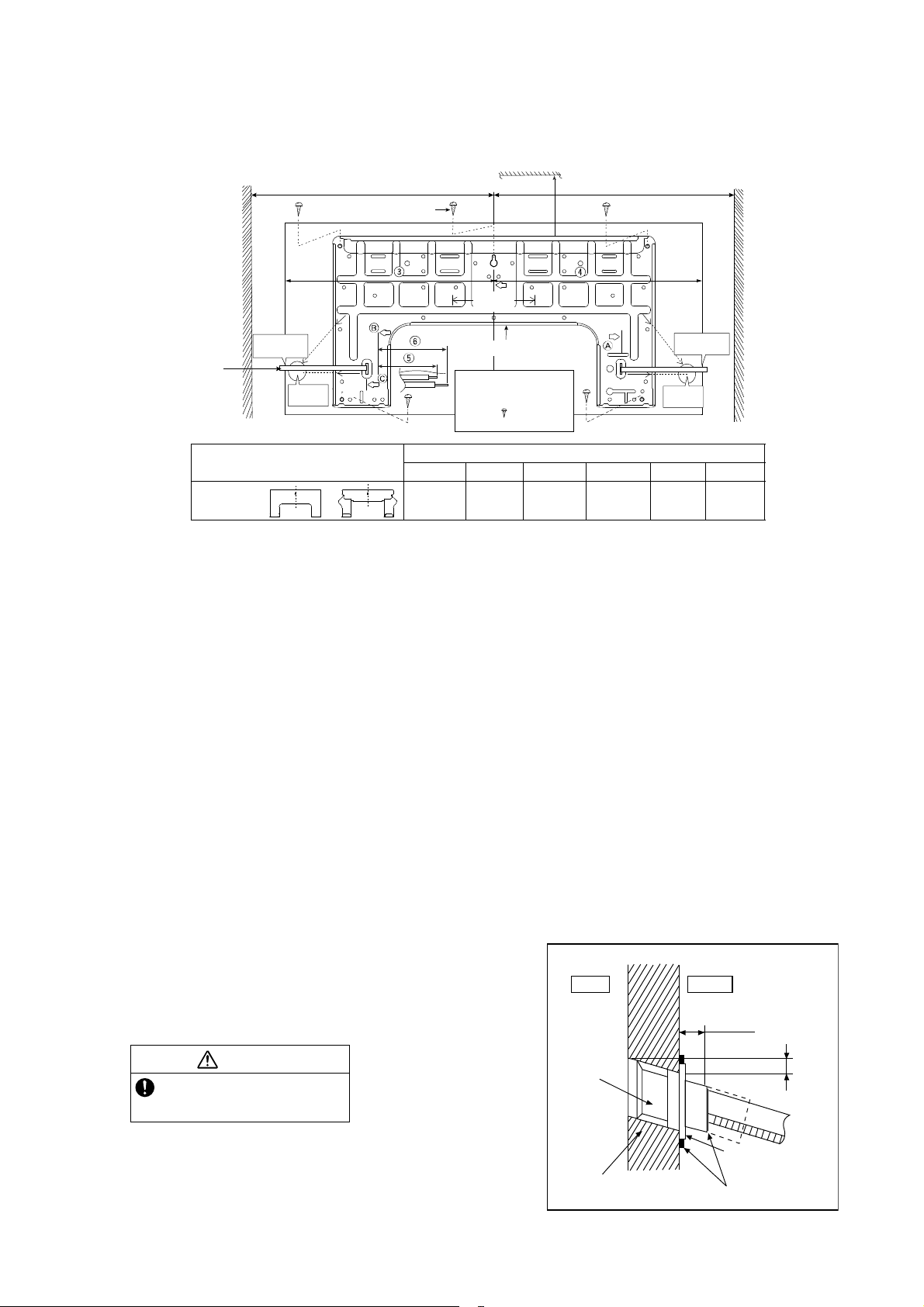
9.2 Indoor Unit
W
9.2.1 How to Fix Installation Plate
The mounting wall shall be strong and solid enough to prevent it from the vibration.
Measuring
T ape
Wal l
917/32"
(241.5 mm )
51/16"
(128 mm)
More than 1
PIPE HOL E CENTER
DISTANCE
TO PIPE
HOLE
CENTER
128 mm
2
screw
51/16"
(128 mm)
Installation plate
For best strength of
INDOOR unit installation,
it is highly recommended
to locate “
as shown.
all
More
than 2
1
”at5position
DISTANCETO
PIPE HOLE
CENTER 128 mm
More than 1
PIPE HOLE
CENTER
917/32"
(241.5 mm )
51/16"
(128 mm)
Wal l
Dimension
179/32"
(439 mm)
17"
(432 mm)
111/16"
(43 mm)
ME7***
Model
123 456
or
199/32"
(490 mm)
37/32"
(82 mm)
The center of installation plate should be at more than at right and left of the wall.
The distance from installation plate edge to ceiling should more than .
From installation plate center to unit’s left side is .
From installation plate center to unit’s right side is .
B : For left side piping, piping connection for liquid should be about from this line.
○
: For left side piping, piping connection for gas should be about from this line.
1 Mount the installation plate on the wall with 5 screws or more (at least 5 screws).
(If mounting the unit on the concrete wall, consider using anchor bolts.)
o Always mount the installation plate horizontally by aligning the marking-off line with the thread and using
a level gauge.
2 Drill the piping plate hole with ø2 3/4" (ø70 mm) hole-core drill.
o Line according to the left and right side of the installation plate. The meeting point of the extended line is
the center of the hole. Another method is by putting measuring tape at position as shown in the diagram
above. The hole center is obtained by measuring the distance namely 5 1/16" (128 mm) for left and right
hole respectively.
o Drill the piping hole at either the right or the left and the hole should be slightly slanting to the outdoor
side.
9.2.2 To Drill a Hole in the Wall and
Install a Sleeve of Piping
1 Insert the piping sleeve to the hole.
2 Fix the bushing to the sleeve.
Wall
Indoor
3 Cut the sleeve until it extrudes about 19/32"
(15 mm) from the wall.
CAUTION
When the wall is hollow, please be sure
to use the sleeve for tube assembly to
prevent dangers caused by mice biting
the connection cable.
Sleeve for
tube
assembly
4 Finish by sealing the sleeve with putty or
caulking compound at the final stage.
3
/4"(ø70mm)
ø2
through hole
33/4"
(95 mm)
Outdoor
19
Putty or caulking compound
/32" (15 mm)
Approx.
Bushing for tube
assembly
7
/32" -9/32"
(5-7 mm )
17
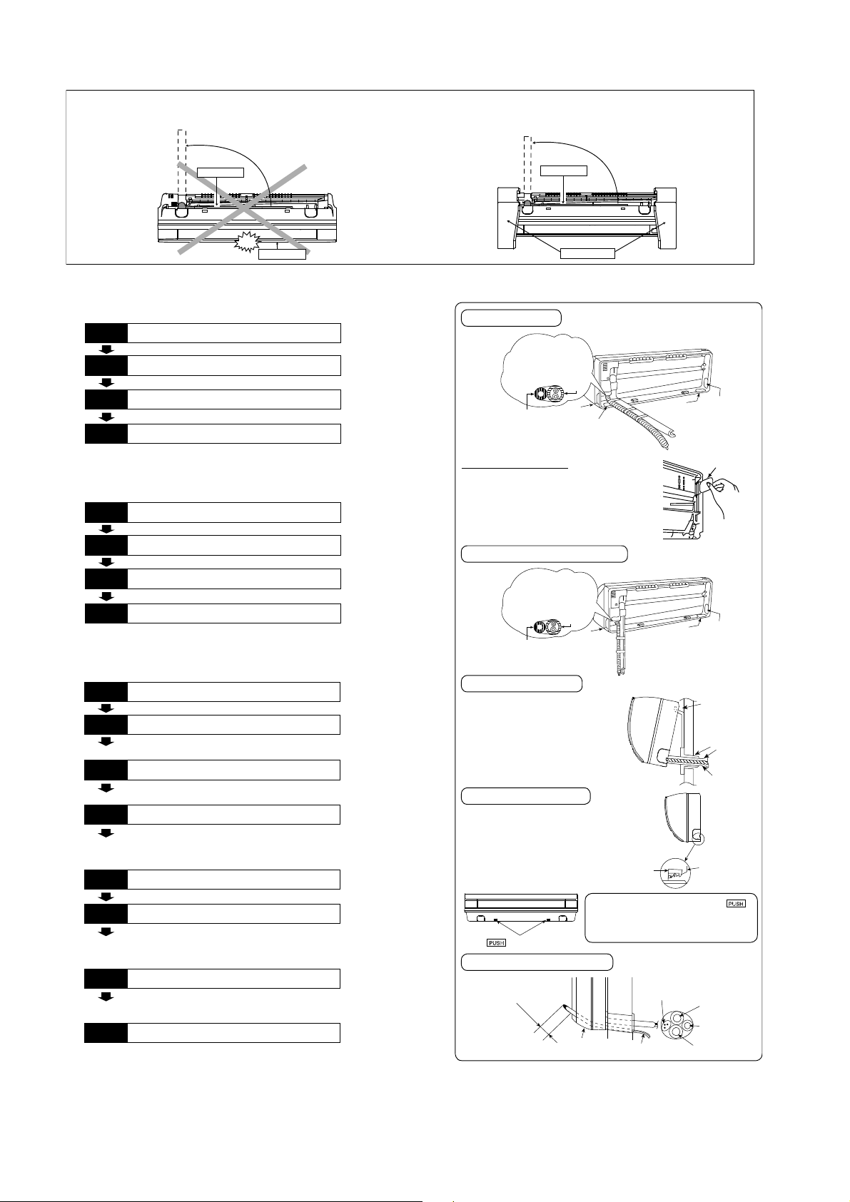
9.2.3 Indoor Unit Installation
Do n ot tu rn over the unit without it’s shock absorber du ring pull out the piping.
It may cause intake grille damage.
Use shock absorber during pull out the piping to p rotect the intake grille from damage.
p
u
l
l
o
u
t
t
h
e
p
i
p
i
n
g
Piping
Piping
p
u
l
l
o
u
t
t
h
e
p
i
p
i
n
g
PUSH PUSH
Intake grille
9.2.3.1 For the right rear piping
Step-1
Step-2
Step-3
Step-4
Pull out the Indoor piping
Install the Indoor Unit
Secure the Indoor Unit
Insert the connection cable
9.2.3.2 For the right bottom piping
Step-1
Step-2
Step-3
Step-4
Pull out the Indoor piping
Install the Indoor Unit
Insert the connection cable
Secure the Indoor Unit
9.2.3.3 For the embedded piping
Step-1
Step-2
Step-3
Step-4
Step-5
Step-6
Step-7
Step-8
Replace the drain hose
Bend the embedded piping
• Use a spring bender or equivalent to bend the
piping so that the piping is not crushed.
Pull the connection cable into Indoor Unit
• The inside and outside connection cable can be
connected without rem oving the front grille.
Cut and flare the embedded piping
• When determining the dimensions of the piping,
slide the unit all the way to the left on the installation
plate.
• Refer to the section “Cutting and flaring the piping”.
Install the Indoor Unit
Connect the piping
• Please refer to “C onnecting the piping” column in
outdoor unit section. (Below steps are done after
connecting the outdoor piping and gas-leakage
confirmatio n .)
Insulate and finish the piping
• Please refer to “Insulation of piping connection”
column as mentioned in indoor/outdoor unit
installation.
Secure the Indoor Unit
PUSH PUSH
Shock absorber
Right Rear piping
T ape it with
piping in a position as
mentioned in
Fig. bel ow.
Piping
Cover for
Drain
the right
piping
Cover for the
bottom piping
hose
Cover for the
bottom piping
Howtokeepthecover
In case of the cover is cut, keep the
cover at the rear of chassis as shown
in the illustration for future
reinstallation.
(Left, right and 2 bottom covers for
piping.)
Cover
for the
left
piping
Cover for pipin g
Right and Right Bottom piping
T ape it with piping in a
position as mentioned in
Fig. below.
Drain hose
Install the indoor unit
Hook the indoor unit onto the upper
portion of installation plate.(Engage
the indoor unit with the upper edge
of the installation plate). Ensure the
hooks are properly seated on the
installation plate by moving it in left
and right.
Piping
Cover for
the right
piping
Cover for the
bottom piping
Indoor unit
Cover for
the left
piping
Hooks at
installation
plate
Sleeve for
piping hole
Piping
Drain hose
Secure the Indoor Unit
1. Press the lower left and right side
of the unit against the installation
plate until hooks engages with their
slot (sound click).
Unit’s
hook
To take out the unit, push the
marking at the bottom unit, and pull it
slightly towards you to disengage the
n
k
m
i
r
a
g
hooks from the unit.
Installation
plate
Insert the connection cable
A
2
b
3
o
/
(
4
u
7
"
t
0
-
-
3
8
5
0
/
m
3
2
m
"
)
Guide
surface
Connection cable
Connection cable
Gas side
piping
Liquid side
piping
Drain hose
(This can be used for left rear piping and bottom
piping also.)
18
Replace the drain hose
Rear view for left piping installation
Drain cap
Drain hose
Connection cable
Drain hose
Adjust the piping slightly downwards.
Piping
Drain hose
Sleeve for pip ing hole
More than 37
Connection
cable
13
/32"(950mm)
How to pull the piping and drain hose out, in case of embedded piping.
•
Apply putty or
caulking material
to seal the wa ll
opening.
PVC tube for
drain hose (VP-20)
PVC tube
for d rain
hose
Drain hose adapter
Join indoor drain hose to 3/4" (20 mm) nominal PVC pipe size
•
by using drain hose adapter
Remarks :
Make sure indoor unit drain hose & 3/4" (20 mm ) nom inal PVC pipe
are fully inserted to drain hose adapter
8
usage
"
16
/
9
More than 27
(700 mm)
Indoor unit
3
when necessary.
8
8
.
h
t
e
r
o
/
M
3
1
7
3
e
r
o
M
"
1/2
18
PVC tube (VP-65) for piping
and connection cable
PVC tube for drain hose (VP-30)
Cable
Piping
15
/16"(100mm)
n
a
2
3
h
t
70
4
(
5
9
(
"
n
a
m
)
m
m
0
Connection
cable
Piping
)
Drain hose
m
from main unit
In case of left piping how to insert the connection
•
cable and drain hose.
°
5
4
Drain
hose
Cable
Piping
(For the right piping, follow the same procedure)
Indoor unit
drain hose
Close join by Vinyl Tape ( )
Drain hose adapter
3/4" (20 mm) nominal PVC pipe
- Install incline downward more than 1°
- Apply PVC glue at the join.
8
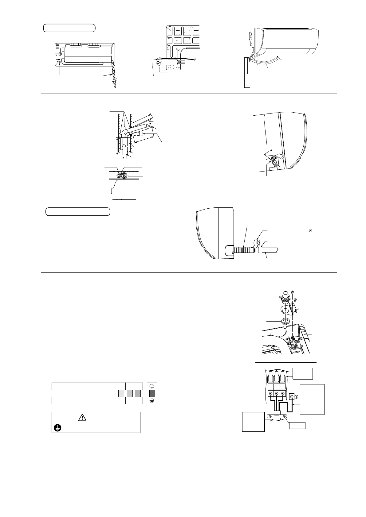
9.2.4 Connect the Cable to the Indoor Unit
1. The inside and outside connection cable can
be connected without removing the front grille.
2. Unscrew the conduit cover and fix the conduit
connector to conduit cover with lock nut, then
secure it against chassis.
3. Connection cable between indoor unit and
outdoor unit should be UL listed or CSA
approved 4 conductor wires minimum AWG16
in accordance with local electric codes.
o Ensure the colour of wires of outdoor unit
and terminal number are the same as the
indoor's respectively
Terminals on the indoor unit 1 2 3
Colour of wires (connection cable)
Terminals on the outdoor unit 1 2 3
WARNING
This equipment must be properly earthed.
o Earth lead wire shall be Yellow/Green
(Y/G) in colour and shall be longer than
other lead wires as shown in the figure for
electrical safety in case of the slipping.
Conduit
Connector
Conduit
Cover
Lock Nut
Chassis
Rear Side of Indoor Unit
Ter m i n a l
Board
Indoor and
outdoor
connection
cable
123
Holder
Earth Wire
longer than
others AC
wires for
safety
reason
19
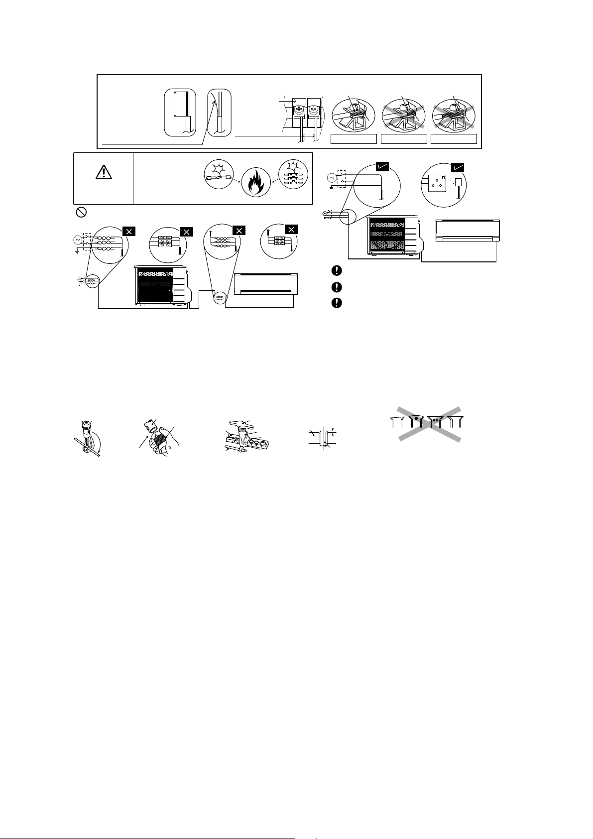
9.2.5 Wiring Stripping and connecting requirement
mproperfla
rin
g
Wire stripping
Indoor/outdoor
connection
terminal board
No loose strand
when inserted
WARNING
Do not joint wires
(10±1 mm)
13/32" ± 1/16"
RISK OF FIRE
JOINING OF WIRES
MAY CAUSE
OVER HEATING
AND FIRE.
7
/32"
(5 mm)
or more
(gap between wires)
Conductor
fully inserted
ACCEPT PROHIBITED PROHIBITED
Conductor
over inserted
OR
Conductor not
fully inserted
OR
OR
Use complete wire without joining.
Use approved socket and plug with ear th pin.
Wire connection in this area must follow to
national wiring rules.
9.2.5.1 Cutting and flaring the piping
1 Please cut using pipe cutter and then remove the burrs.
2 Remove the burrs by using reamer. If burrs is not removed, gas leakage may be caused.
Turn the piping end down to avoid the metal powder entering the pipe.
3 Please make flare after inserting the flare nut onto the copper pipes.
1
Bar
0–
/32"
(0-0.5 mm)
Copper
pipe
When properly flared, the internal surface of the
flare will evenly shine and be of even thickness.
Since the flare part comes into contact with the
connections, carefully c heck the flare finish.
.Tocut
Pipe
Poin t down
2. T o remove burrs
Reamer
Bar
Clamp handle
3. To flare
Handle
Yo k e
Core
Red arrow mark
I
Inclined Surface
damaged
Cracked Uneven
thickness
20
10. Operation Control
10.1 Basic Function
Inverter control, which equipped with a microcomputer in determining the most suitable operation mode as time
passes, automatically adjusts output power for maximum comfort always. In order to achieve the suitable operation
mode, the microcomputer maintains the set temperature by measuring the temperature of the environment and
performing temperature shifting. The compressor at outdoor unit is operating following the frequency instructed by
the microcomputer at indoor unit that judging the condition according to internal setting temperature and intake air
temperature.
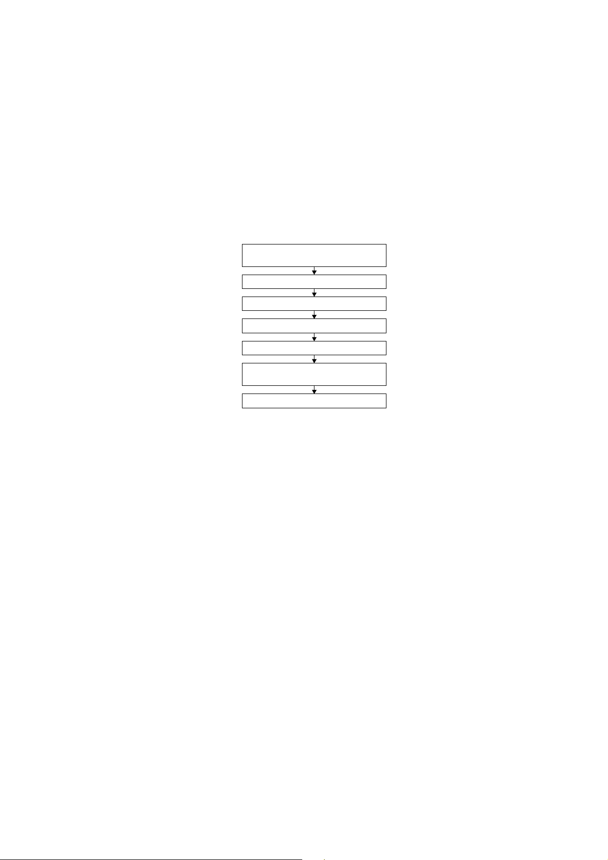
10.1.1 Internal Setting Temperature
Once the operation starts, remote control setting temperature will be taken as base value for temperature shifting
processes. These shifting processes are depending on the air conditioner settings and the operation environment.
The final shifted value will be used as internal setting temperature and it is updated continuously whenever the
electrical power is supplied to the unit.
Remote Control Setting Temperature
Outdoor Air Temperature Shifting
60.8°F - 86°F
Auto Operation Mode Shifting
Indoor Air Temperature Shifting
Powerful Mode Shifting
Setting Temperature Limit Checking
(Min: 60.8°F; Max 91.4°F)
Internal Setting Temperature
10.2 Cooling operation
10.2.1 Thermostat control
Capability supply to indoor unit is OFF (Expansion valve closed) when Intake Air Temperature - Internal setting
temperature < -3.6°F.
Capability resume supply to indoor unit after waiting for 3 minutes, if the Intake Air temperature - Internal setting
temperature > Capability supply OFF point.
10.3 Soft Dry Operation
10.3.1 Thermostat control
Capability supply to indoor unit is OFF (Expansion valve closed) when Intake Air Temperature - Internal setting
temperature < -5.4°F.
Capability resume to indoor unit after waiting for 3 minutes, if the Intake Air temperature - Internal setting
temperature > Capability supply OFF point.
10.4 Heating Operation
10.4.1 Thermostat control
Capability supply to indoor unit is OFF (Expansion valve closed) when Intake Air Temperature - Internal setting
temperature > 1.8°F.
During this condition, the indoor fan is stopped if compressor is ON.
Capability resume supply to indoor unit after waiting for 3 minutes, if the Intake Air Temperature - Internal setting
temperature < Capability supply OFF point.
21
10.4.2 Temperature Sampling Control
Temperature sampling is controlled by outdoor unit where room temperature for all power supply ON indoor unit
could be obtained.
When capability supply to the indoor unit is OFF and the compressor is ON during heating operation, the indoor
fan motor is stopped. During this condition, 15 seconds after sampling signal from outdoor unit is received, the
indoor fan start operation at low fan speed.
However, within first 4 minutes of capability stopped supply to the indoor unit, even sampling signal is received,
the sampling control is cancelled.
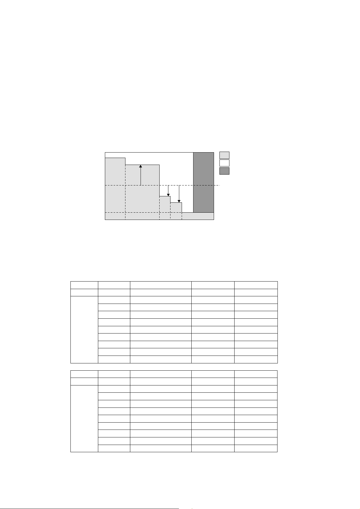
10.5 Automatic Operation
This mode can be set using remote control and the operation is decided by remote control setting temperature,
remote control operation mode, indoor intake and outdoor air temperature.
During operation mode judgment, indoor fan motor (with speed of -Lo) and outdoor fan motor are running for
30 seconds to detect the indoor intake and outdoor air temperature. The operation mode is decided based on
below chart.
Indoor intake air
temperature (F)
96.8
Heating Mode
Soft Dry Mode
T1
T2
T3
Cooling Mode
Remote Control
setting temperature
60.8
66.255.4 69.8 73.4 77
10.6 Indoor Fan Speed Control
Indoor Fan Speed can be set using remote control.
10.6.1 Fan Speed Rotation Chart
Mode Fan Tap Application rpm rpm
SHi Pwr Me+ 1080 1110
Hi Fc, RC 990 1020
Me+ RC 900 930
Me RC 820 840
COOL
Mode Fan Tap Application rpm rpm
HEAT
Me- RC 740 750
Lo Fcmin, RC 660 660
Lo- QuietLo 570 570
SLo Dry 550 550
SSLo Auto Cut 540 540
SSHi Pwr Me+ 1210 1240
SHi Fh, RC 1120 1150
Me+ RC 1030 1050
Me RC 950 960
Me- RC 860 870
Lo Fhmin, RC 780 780
Lo- QuietLo 690 690
SLo Thermo Off, Hot start 580 580
SSLo Thermo Off 570 570
Outdoor air
temperature (F)
ME5RKUA ME7RKUA
ME5RKUA ME7RKUA
22
10.7 Indoor Fan Motor Operation
H
FanS
M
10.7.1 Residual Heat Removal Control
To prevent high pressure at indoor unit, when heating mode thermostat-off condition or power supply OFF,
indoor fan continue to operate at controlled fan speed for maximum 30 seconds then stop.
10.7.2 Basic Rotation Speed (rpm)
Manual Fan Speed
[Cooling, Dry]
o Fan motor’s number of rotation is determined according to remote control setting.
Remote control ○ ○ ○ ○ ○
Tab Hi Me+ Me Me- Lo
[Heating]
o Fan motor’s number of rotation is determined according to remote control setting.
Remote control ○ ○ ○ ○ ○
Tab Shi Me+ Me Me- Lo
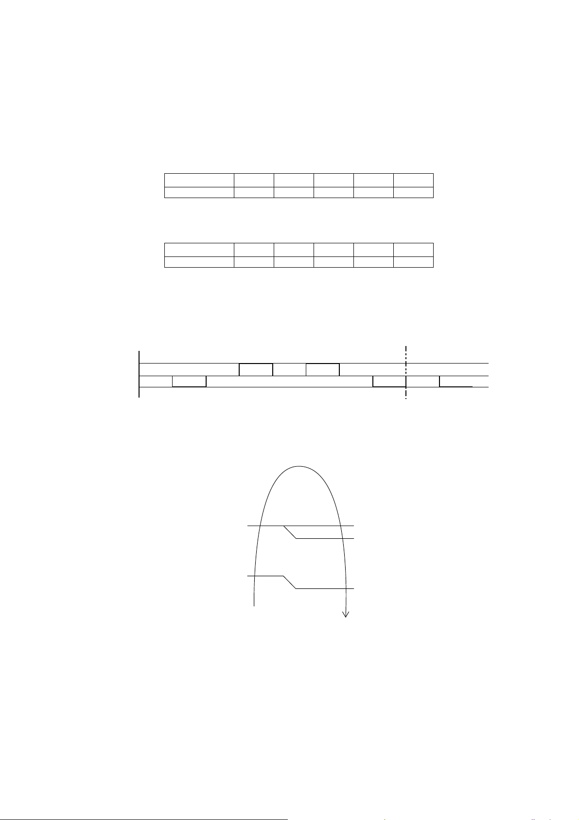
Auto Fan Speed
[Cooling, Dry]
o According to room temperature and setting temperature, indoor fan speed is determined automatically.
o The indoor fan will operate according to pattern below.
peed
igher
edium
Lower
abc def gh
o During operation, indoor fan motor may stop due to odor prevention.
[Heating]
o According to indoor pipe temperature, automatic heating fan speed is determined as follows.
[1 pattern : 10 s]
ab
RPM Increased
o
F
102.2
o
F
66.2
Indoor Pipe Temp.
RPM Maintain
RPM Reduced
OFF
95oC
60.8oF
Feedback control
o Immediately after the fan motor started, feedback control is performed once every second.
o During fan motor on, if fan motor feedback ≥ 2550 rpm or < 50 rpm continue for 10 seconds, then fan motor
error counter increase, fan motor is then stop and restart. If the fan motor counter becomes 7 times, then
H19 - fan motor error is detected. Operation stops and cannot on back.
23
 Loading...