

Panasonic CS-ME7, CS-ME10, CS-ME12, CS-ME14CB1P, CS-ME14 Service Manual
...
Multi Air Conditioner
CS-ME7CB1P
CS-ME10CB1P
CS-ME12CB1P
CS-ME14CB1P
CS-ME10CD3P
CS-ME14CD3P
ORDER NO. RAC0312001A8
Please file and use this manual together with the service manual for Model No. CS-ME7CKPG, CSME10CKPG, CS-ME12CKPG, CS-ME14CKPG, CS-ME18CKPG, CU-2E15CBPG, CU-2E18CBPG, CU3E23CBPG, CU-4E27CBPG, Order No. RAC0209005C2.
CONTENTS
Page Page
1 Features 3
2 About Lead Free Solder (PbF)
2.1. DISTINCTION OF PbF P.C. BOARD
2.2. CAUTION
3 Functions
3.1. REMOTE CONTROL
3.2. INDOOR UNIT
4 Product Specifications
5 Dimensions
3
3
3
4
4
5
7
8
5.1. Cassette Type 8
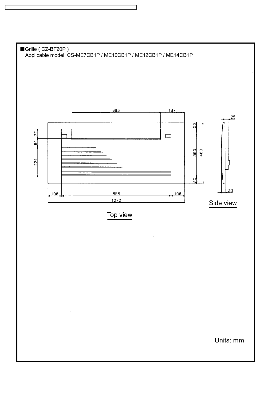
5.2. Grille
5.3. Duct Type
6 Refrigeration Cycle Diagram
7 Block Diagram
8 Wiring Diagram
8.1. Cassette Type (CS-
ME7CB1P/ME10CB1P/ME12CB1P/M E14CB1P)
8.2. Duct Type (CS-ME10CD3P/ME14CD3P)
10
11
12
13
14
14
15
© 2003 Matsushita Electric Industrial Co., Ltd. All
rights reserved. Unauthorized copying and
distribution is a violation of law.

CS-ME7CB1P / CS-ME 10CB1P / CS-ME12CB1 P / CS-ME14CB1 P / CS-ME10CD3P / CS-ME14CD3P
9 Operation Details (Functions & Protection) 16
9.1. Simultaneous Operation Control
9.2. Airflow Direction Control (Cassette Type only)
9.3. Indoor Fan Control
9.4. Drain Pump Control
9.5. Auto Restart Control
9.6. Other Indoor Unit Operation Functions
10 Installation Instructions
10.1. Cassette Type
10.2. Duct Type
11 Operating Instructions
12 Disassembly of Parts
16
17
18
20
21
22
30
30
35
41
53
12.1. Cassette Type (Indoor Unit: CS-
ME7CB1P/ME10CB1P/ME12CB1P/M E14CB1P)
12.2. Duct Type (Indoor Unit: CS-ME10CD3P/ME14CD3P)
13 Technical Data
13.1. OPERATION CHARACTERISTICS
14 Electronic Circuit Diagram
14.1. REMOTE CONTROL
14.2. Cassette Type
14.3. Duct Type
15 Exploded View & Replacement Parts List
15.1. CS-ME7CB1P/ME10CB1P/ME12CB1 P/ME14CB1P
15.2. CS-ME10CD3P/ME14CD3P
53
57
59
59
63
63
64
65
66
66
68
2
CS-ME7CB1P / CS-ME 10CB1P / CS-ME12CB1 P / CS-ME14CB1 P / CS-ME10CD3P / CS-ME14CD3P
1 Features
· Product
−
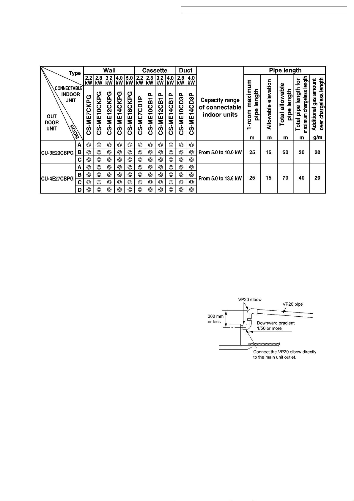
− A single OUTDOOR unit enables air conditioning of up to four separate rooms
− −
Remarks:
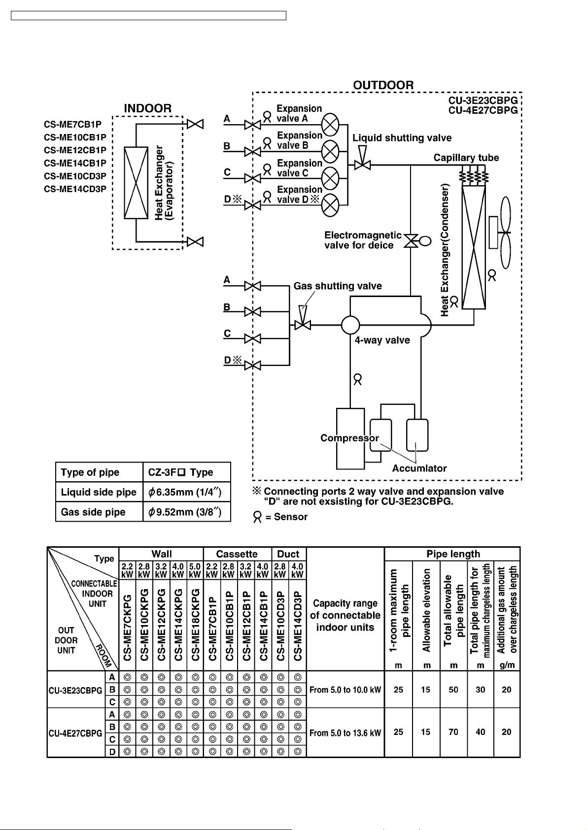
1. At least two indoor units must be connected.
2. The total nominal cooling capacity of indoor units that will be connected to outdoor unit must be within connectable
capacity range of outdoor unit. (Shown in the above table)
Example: The below indoor units combination is not possible to connect CU-3E23CBPG. (Total nominal capacity
of indoor unit is between 5.0kW and 10.0kW)
1) Two CS-ME7CB1P only. (Total nominal cooling capacity is 4.4kW)
2) Three CS-ME14CB1P only. (Total nominal cooling capacity is 12.0kW )
−
− Inverter controlled for High energy efficiency and optimal comfort
− −
−
− New refrigerant R410A is used for protecting ozone layer
− −
−
− Lead - free P.C. Board
− −
· Serviceability
−
− Self diagnosis
− −
−
− Test Run at both Cooling and Heating rated frequency
− −
· Built-in drain pump (Cassette and Duct type)
−
− A drain pump is built in.
− −
The pipe can rise to 200 mm above the drain outlet.
2 About Lead Free Solder (PbF)
2.1. DISTINCTION OF PbF P.C. BOARD
P.C. Boards (manufactured) using lead free solder will have a PbF stamp on the P.C. Board.
2.2. CAUTION
· Pb free solder has a higher melting point than standard solder; Typically the melting point is 50 - 70 °F (30 - 40 °C) higher.
Please use a high temperature solder iron and set it to 700 ± 20 °F (370 ± 10 °C).
· Pb free solder will tend to splash when heated too high (about 1100 °F/ 600 °C).
If you must use Pb solder, please completely remove all of the Pb free solder on the pins or solder area before applying Pb
solder. If this is not practical, be sure to heat the Pb free solder until it melts, before applying Pb solder.
3
CS-ME7CB1P / CS-ME 10CB1P / CS-ME12CB1 P / CS-ME14CB1 P / CS-ME10CD3P / CS-ME14CD3P
3 Functions
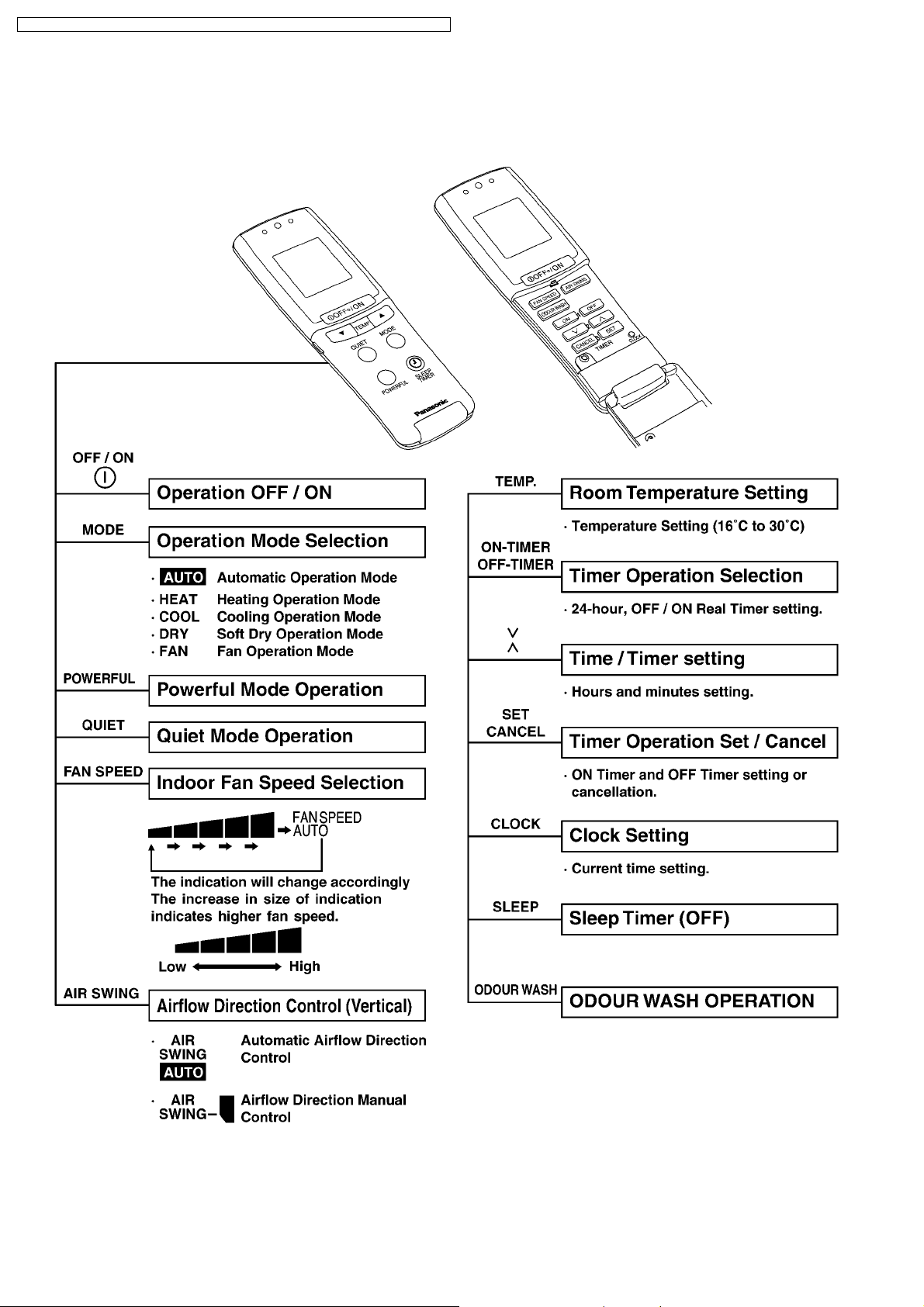
3.1. REMOTE CONTROL
4
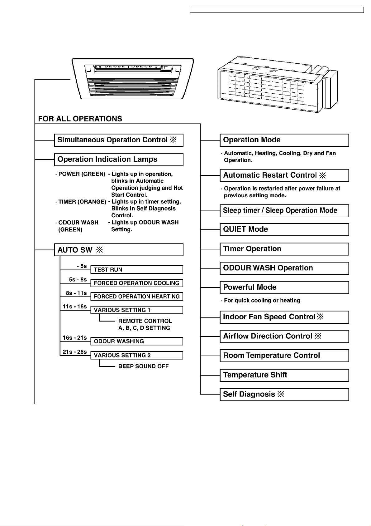
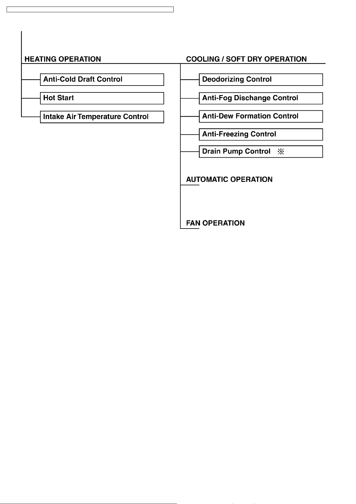
3.2. INDOOR UNIT
CS-ME7CB1P / CS-ME 10CB1P / CS-ME12CB1 P / CS-ME14CB1 P / CS-ME10CD3P / CS-ME14CD3P
5
CS-ME7CB1P / CS-ME 10CB1P / CS-ME12CB1 P / CS-ME14CB1 P / CS-ME10CD3P / CS-ME14CD3P
6
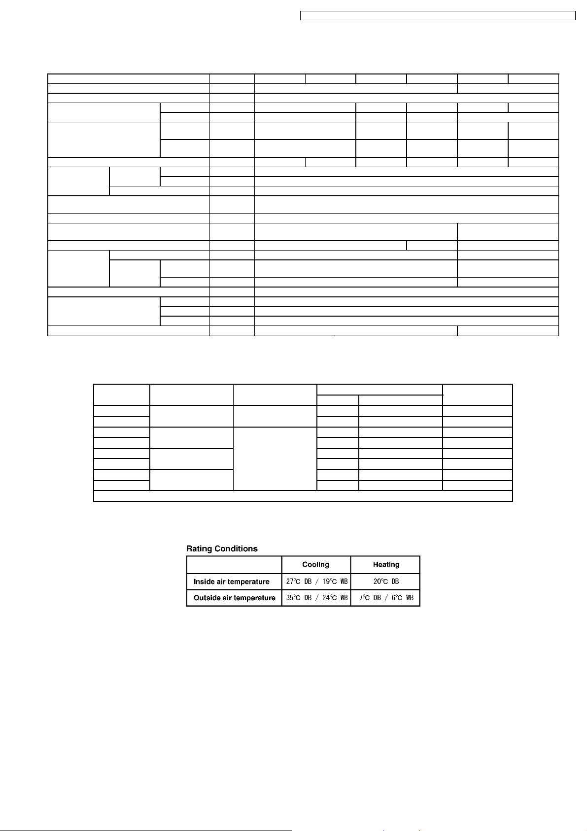
4 Product Specifications
CS-ME7CB1P / CS-ME 10CB1P / CS-ME12CB1 P / CS-ME14CB1 P / CS-ME10CD3P / CS-ME14CD3P
Item Cassette Type Duct Type
Power Source Outdoor power (single 230V 50Hz)
Air Volume Cooling m3/min. 9.1 9.6 9.5 7.0 7.8
Noise Level Cooling
Moisture Removal L/h 1.3 1.6 1.8 2.3 1.6 2.3
Refrigeration
piping
Type of Indoor/Outdoor connecting
cable
Drain opening mm VP20
Dimensions mm Height 185 x Width 770 x Depth 360 Height 235 x Width 750
Net Weight kg 9.8 10.5 16.5
Fan Type Cross-flow fan Sirocco fan
Heat exchanger Plate fin forced-draft
Adjustments Switches Wireless remote control
Air filter PP honeycomb -
Connection Liquid mm 6.35 (1/4") Flare to the main unit
Type of pipe CZ-3F
Motor Type DC brushless motor (EHOCM24A4P25) DC brushless motor
Model CS-ME7CB1P CS-ME10CB1P CS-ME12CB1P CS-ME14CB1P CS-ME10CD3P CS-ME14CD3P
Heating m3/min. 9.8 10.2 9.8 8.7
(Power)
Heating
(Power)
Gas mm 9.52 (3/8") Flare to the main unit
Output W 4P 25W 40V A98258 8P 30W 280-340V A981071
Timer Timer with ON and OFF times programmable
Temperature Electronic thermostat
dB(A)
(dB)
dB(A)
(dB)
mm 4 x 1.5 mm2flexible cord, type designation 245 IEC 57 (H05RN-F)
Hi:40(53)
Lo:32(45)
Hi:42(55)
Lo:32(45)
Hi:41(54)
Lo:32(45)
Hi:43(56)
Lo:32(45)
Hi:43(56)
Lo:32(45)
Hi:44(57)
Lo:34(47)
Hi:43(56)
Lo:32(45)
Hi:47(60)
Lo:32(45)
x Depth 370
(ARW31V8P30AC)
Hi:45(58)
Lo:32(45)
Hi:47(60)
Lo:35(48)
Remarks:
The specifications are differ from wall type indoor units when 2.8kW Duct type is connected to CU-2E15CBPG and CU2E18CBPG.
Indoor unit
Combination
Cooling 22 + 28 CU-2E15CBPG 1.39 0.25 - 1.73 6.50
Heating 1.36 0.21 - 1.67 6.05
Cooling 22 + 28 CU-2E18CBPG 1.39 0.25 - 1.73 6.50
Heating 1.36 0.21 - 1.67 6.05
Cooling 28 + 28 (*) 1.56 0.25 - 1.73 7.25
Heating 1.47 0.21 - 1.74 6.50
Cooling 28 + 32 1.67 0.25 - 1.80 7.80
Heating 1.39 0.21 - 1.72 6.15
(*) The combination 2.8kW Duct type X 2 and 2.8kW Duct type + 2.8kW Wall type are same value.
Outdoor unit Power Input (kW) Current (A)
min. - max
* Specifications are subject to change without notice for further improvement.
7
CS-ME7CB1P / CS-ME 10CB1P / CS-ME12CB1 P / CS-ME14CB1 P / CS-ME10CD3P / CS-ME14CD3P9CS-ME7CB1P / CS-ME 10CB1P / CS-ME12CB1 P / CS-ME14CB1 P / CS-ME10CD3P / CS-ME14CD3P
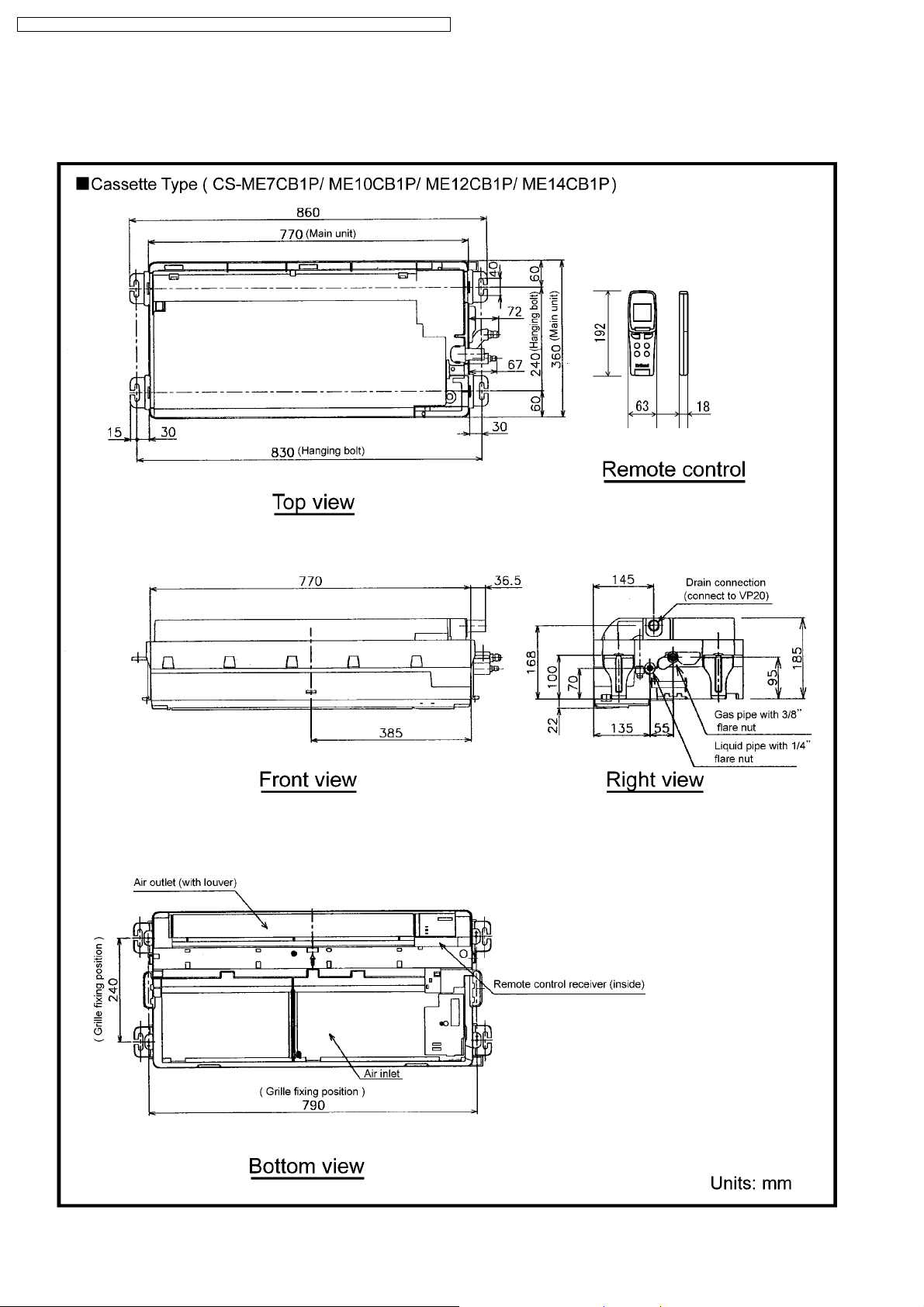
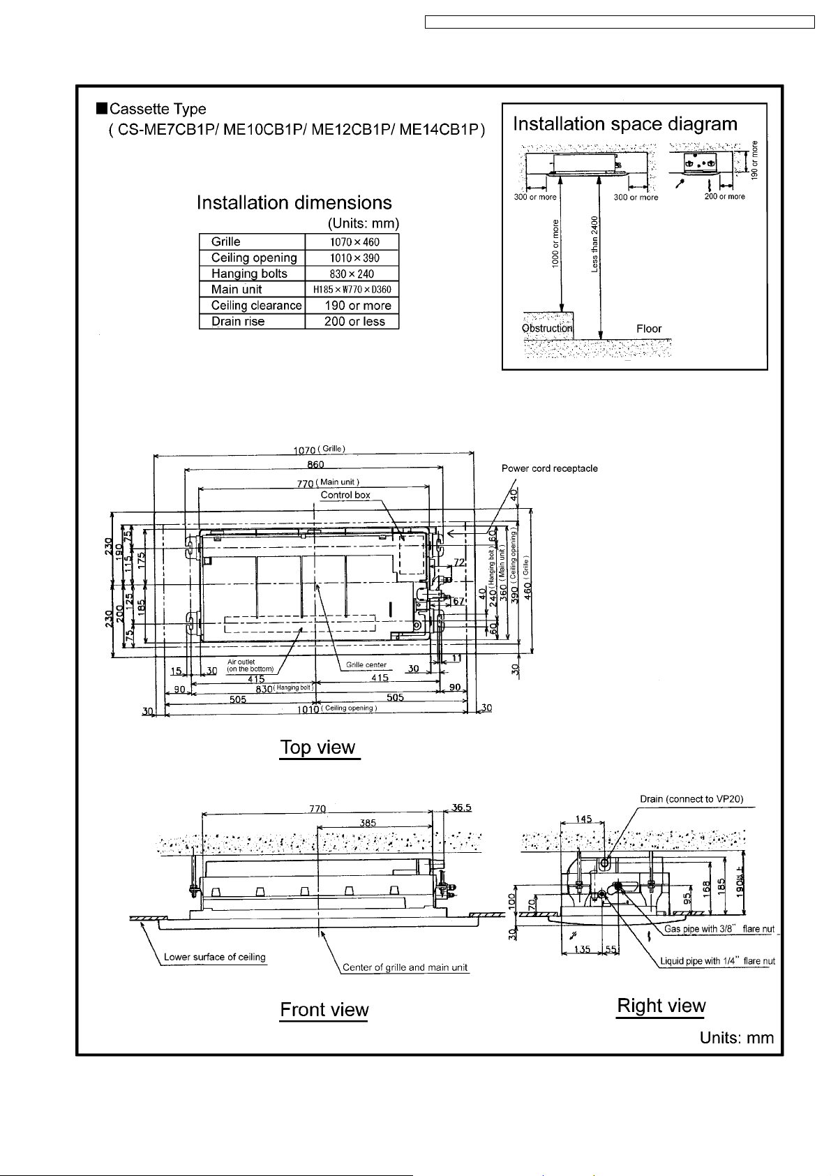
5 Dimensions
5.1. Cassette Type
8
CS-ME7CB1P / CS-ME 10CB1P / CS-ME12CB1 P / CS-ME14CB1 P / CS-ME10CD3P / CS-ME14CD3P
5.2. Grille
10
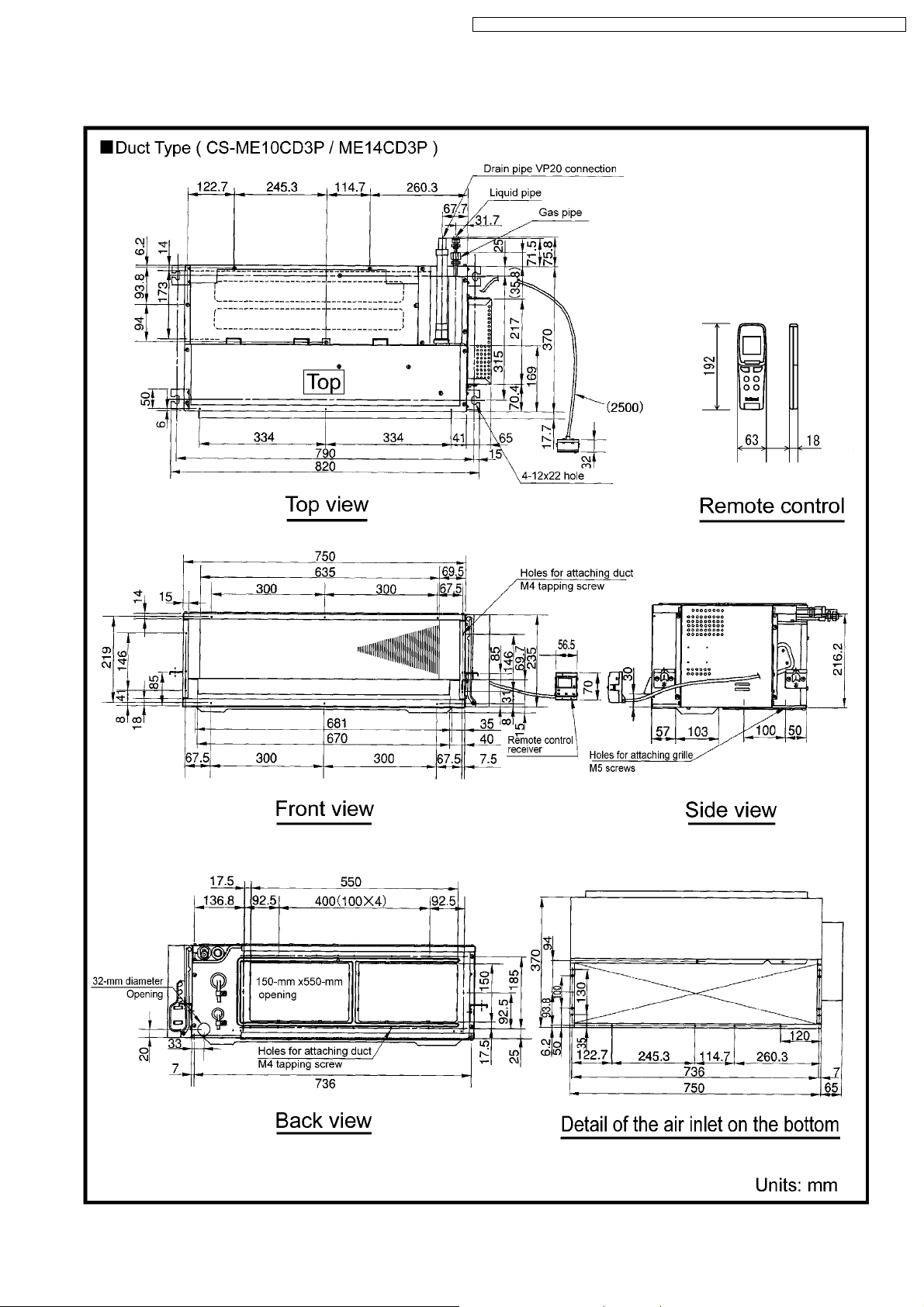
5.3. Duct Type
CS-ME7CB1P / CS-ME 10CB1P / CS-ME12CB1 P / CS-ME14CB1 P / CS-ME10CD3P / CS-ME14CD3P
11
CS-ME7CB1P / CS-ME 10CB1P / CS-ME12CB1 P / CS-ME14CB1 P / CS-ME10CD3P / CS-ME14CD3P
6 Refrigeration Cycle Diagram
12
CS-ME7CB1P / CS-ME 10CB1P / CS-ME12CB1 P / CS-ME14CB1 P / CS-ME10CD3P / CS-ME14CD3P
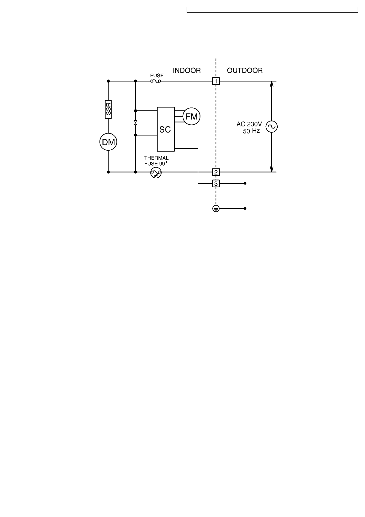
7 Block Diagram
CS-ME7CB1P/ME10CB1P/ME12CB1P/ME14CB1P/ME10CD3P/ME14CD3P
13
CS-ME7CB1P / CS-ME 10CB1P / CS-ME12CB1 P / CS-ME14CB1 P / CS-ME10CD3P / CS-ME14CD3P
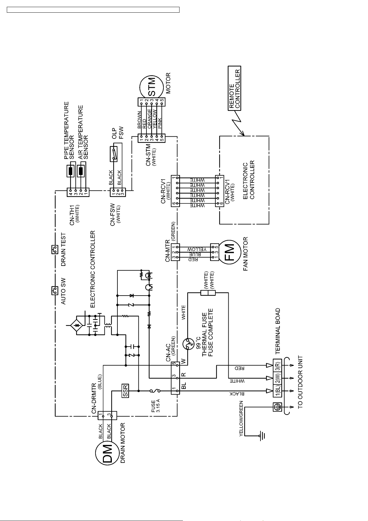
8 Wiring Diagram
8.1. Cassette Type (CS-ME7CB1P/ME10CB1P/ME12CB1P/ME14CB1P)
14
CS-ME7CB1P / CS-ME 10CB1P / CS-ME12CB1 P / CS-ME14CB1 P / CS-ME10CD3P / CS-ME14CD3P
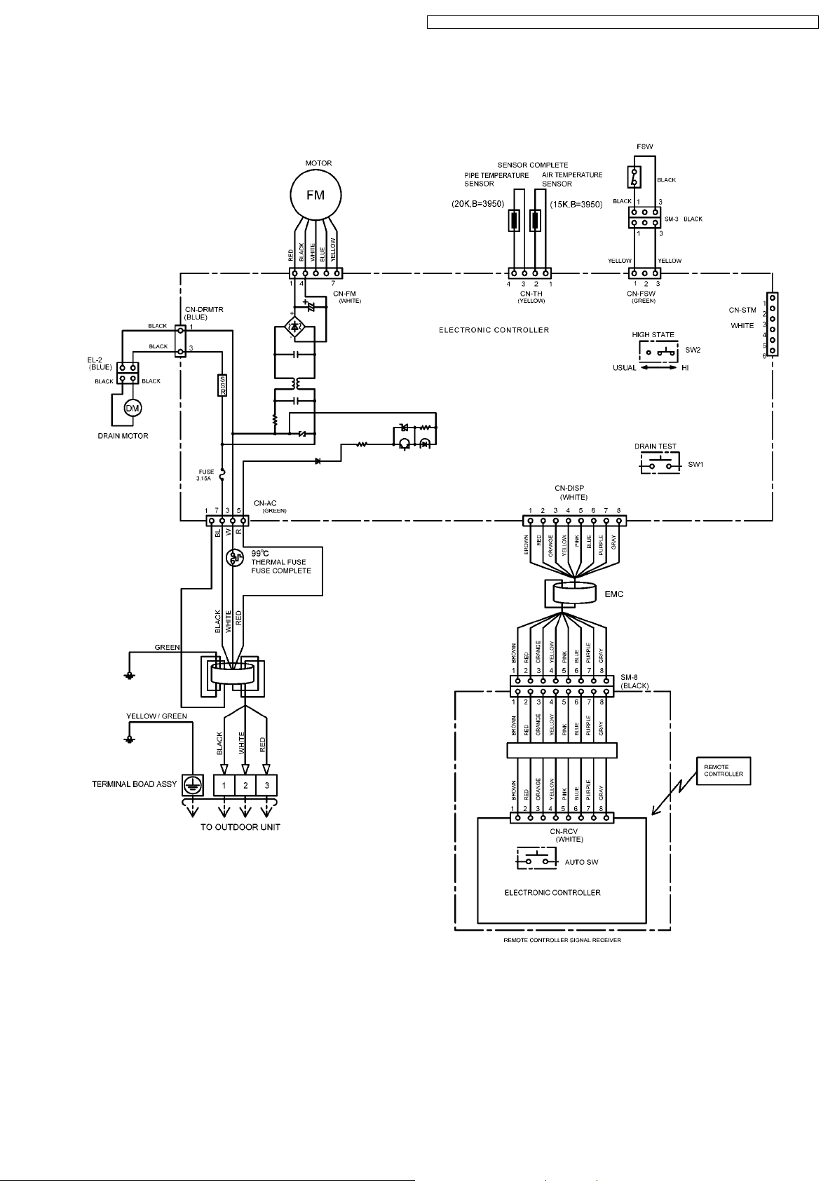
8.2. Duct Type (CS-ME10CD3P/ME14CD3P)
15
CS-ME7CB1P / CS-ME 10CB1P / CS-ME12CB1 P / CS-ME14CB1 P / CS-ME10CD3P / CS-ME14CD3P
9 Operation Details (Functions & Protection)
9.1. Simultaneous Operation Control
1. Operation modes which can be selected using the remote
control unit: Automatic, Cooling, Dry, Heating, Fan operation mode.
2. Types of operations modes which can be performed
simultaneously
· Cooling operation and cooling, Dry or fan operation
· Heating operation and heating operation
3. Types of operation modes which cannot be performed
simultaneously
· While a cooling operation is in progress, a heating operation
cannot be performed by an indoor unit in another room.
In the room where the operation button for cooling was pressed
first, the operation is continued. In the room where the operation
button for heating was pressed afterward, the operation lamp of
the indoor unit blinks, where the attempt is made to establish the
heating operation. Its fan is stopped, and the air does not
discharged.
· While a heating operation is in progress, a cooling operation
cannot be performed by an indoor unit in another room.
In the room where the operation button for heating was pressed
first, operation is continued. In the room where the operation
button for cooling was pressed afterward, the operation lamp of
the indoor unit blinks, where the attempt is made to establish the
cooling operation. Its fan is stopped, and the air does not
discharged.
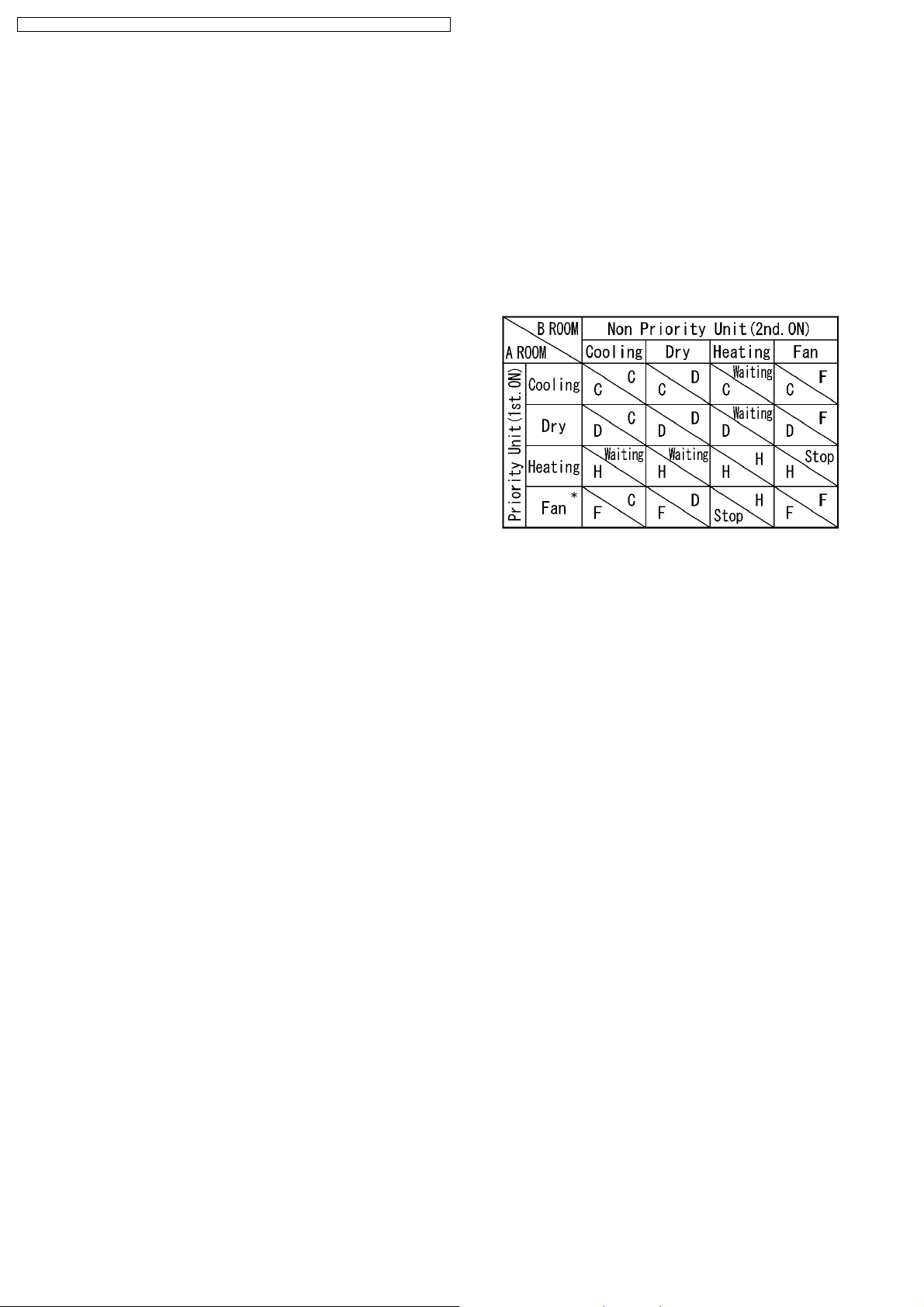
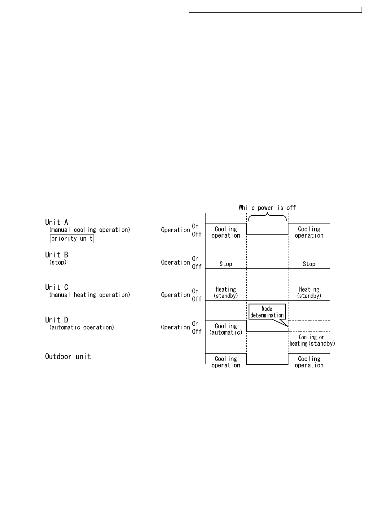
4. Operation mode priority control
· The operation mode designated first by the indoor unit has
priority.
· If the priority indoor unit stops operation or initiates the fan
operation, the priority is transferred to other indoor units.
“Waiting” denotes the standby status in which the operation
lamp LED blinks (ON for 2.5 sec. and OFF for 0.5 sec.), and
the fan is stopped.
* In the fan mode, priority is transferred to a non-priority unit.
Note
C: Cooling operation mode
D: Dry operation mode
H: Heating operation mode
F: Fan operation mode
16
CS-ME7CB1P / CS-ME 10CB1P / CS-ME12CB1 P / CS-ME14CB1 P / CS-ME10CD3P / CS-ME14CD3P
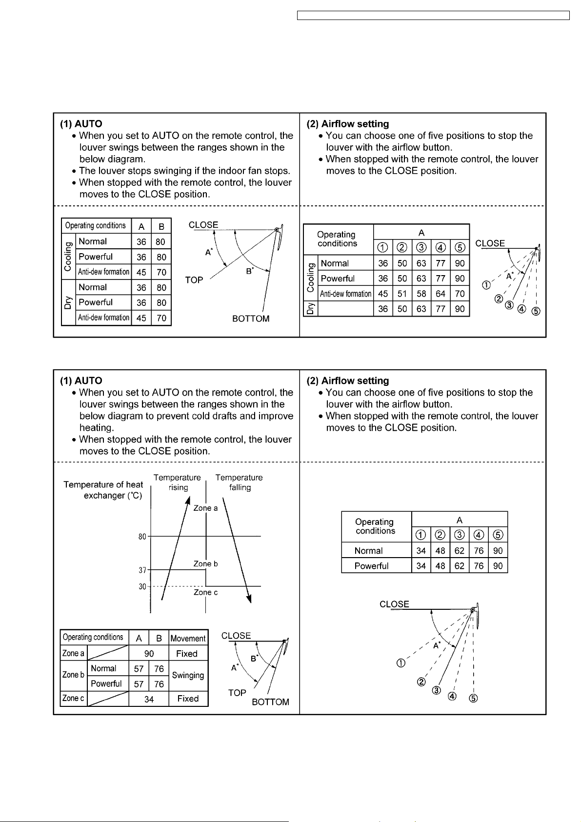
9.2. Airflow Direction Control (Cassette Type only)
The following shows how louver operation changes depending on the direction set with the AIR SWING button and other operating
conditions.
Cooling and Dry
Heating
· The louver stops at the CLOSE position when the power switch or breaker is ON.
· The louver stops at their current position when the power switch or breaker is OFF.
· Move the horizontal airflow direction control louver manually.
17
CS-ME7CB1P / CS-ME 10CB1P / CS-ME12CB1 P / CS-ME14CB1 P / CS-ME10CD3P / CS-ME14CD3P19CS-ME7CB1P / CS-ME 10CB1P / CS-ME12CB1 P / CS-ME14CB1 P / CS-ME10CD3P / CS-ME14CD3P
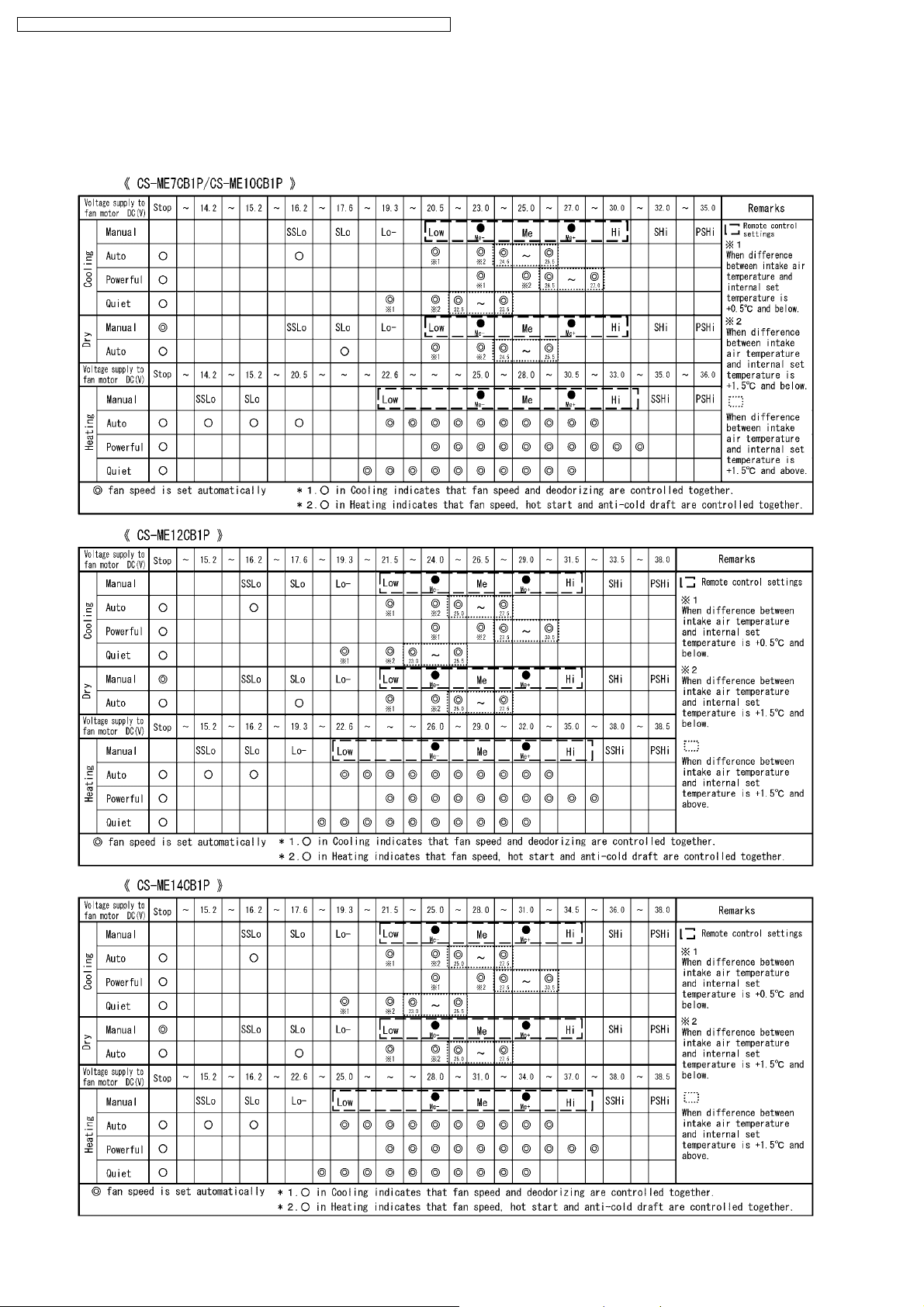
9.3. Indoor Fan Control
· The following shows how fan speed changes depending on the setting made with the FAN SPEED button and other operating
conditions.
· Actual fan speed may differ from that you set with remote control.
18

CS-ME7CB1P / CS-ME 10CB1P / CS-ME12CB1 P / CS-ME14CB1 P / CS-ME10CD3P / CS-ME14CD3P
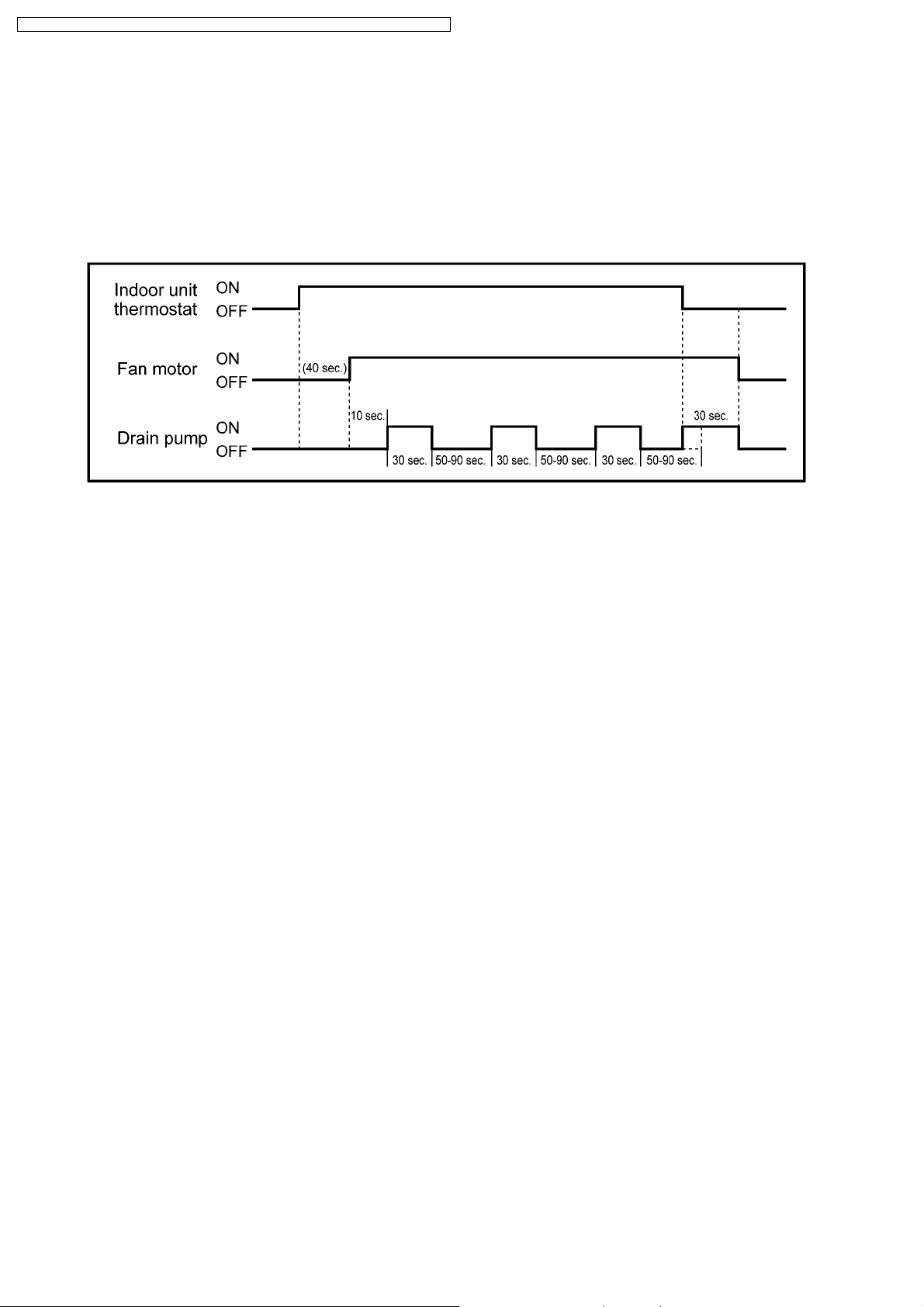
9.4. Drain Pump Control
Basic operation
· The drain pump starts 50 seconds after the indoor unit starts or the thermostat comes on (i.e., 10 seconds after the fan
motor starts).
The drain pump stops 30 seconds after the indoor unit stops or the thermostat turns off.
· The drain pump repeats a cycle of on for 30 seconds then off for between 50 and 90 seconds as long as the unit is
operating. Operation while the unit is off is determined by the difference between the temperature setting and the room
temperature.
Float switch operation
· W hen the float switch turns on for 10 seconds continuously, the thermostat of the indoor unit turns off and the drain pump
operates continuously.
· W hen the float switch stays on for 150 seconds continuously, the drain pump and indoor unit stop and the timer lamp
flashes indicating an H21 error.
20
CS-ME7CB1P / CS-ME 10CB1P / CS-ME12CB1 P / CS-ME14CB1 P / CS-ME10CD3P / CS-ME14CD3P
9.5. Auto Restart Control
· if there is a power failure, operation will automatically be restarted when the power is resumed. It will start with the previous
operation mode and airflow direction. (Time Delay Safety Control is valid)
1. Control start conditions
<1> The 24-hour timer must not be set.
<2> The sleep timer must not be set.
Auto restart control is not available when timer or sleep mode is set.
2. Description of control
<1> In the case of manual operation, the operation mode, temperature setting, fan speed and airflow direction before the power
is turned off are restored.
<2> In the case of automatic operation, after the power is restored operation starts with the determination of the mode.
<3> While the air conditioner odour clear timer has been set, the setting is cancelled, and operation is transferred to the mode
before the power is turned off.
<4> While the air conditioner odour clear operation (with timer / without timer setting) are being performed, both of these
operations are completed, and operation is transferred to the operation mode prior to these operations.
Example: When the power is turned off during an outdoor unit cooling operation
21
 Loading...