

Order No. MAC0501021C2
Air Conditioner
CS-E15DKDW CU-E15DKD
CS-E18DKDW CU-E18DKD
CS-E21DKDS CU-E21DKD
CONTENTS
Page Page
1 Features 2
2 Functions
2.1. Remote Control
2.2. Indoor Unit
2.3. Outdoor Unit
3 Product Specifications
3.1. CS-E15DKDW CU-E15DKD
3.2. CS-E18DKDW CU-E18DKD
3.3. CS-E21DKDS CU-E21DKD
4 Dimensions
4.1. Indoor Unit & Remote Control
4.2. Outdoor Unit
5 Refrigeration Cycle Diagram 15
3
6 Block Diagram
7 Wiring Diagram
3
8 Operation Details
4
5
6
6
8
10
12
12
14
8.1. Basic Function
8.2. Protection Control Features
9 Operating Instructions
9.1. CS-E15DKDW
9.2. CS-E18DKDW CS-E21DKDS
10 Installation And Servicing Air Conditioner Using R410A
10.1. Outline
10.2. Tools For Installing/Servicing Refrigerant Piping
© 2005 Panasonic HA Air-Conditioning (M) Sdn Bhd
(11969-T). All rights reserved. Unauthorized copying
and distribution is a violation of law.
16
17
18
18
35
47
47
53
59
59
60

CS-E15DKDW CU-E15DKD / CS-E1 8DKDW CU-E18DKD / CS-E21DKD S CU-E21DKD
10.3. Refrigerant Piping Work 64
10.4. Installation, Transferring, Servicing
11 Installation Instructions
11.1. Safety Precautions
11.2. Indoor Unit
11.3. Outdoor Unit
12 Installation Instructions
12.1. Safety Precautions
12.2. Indoor Unit
12.3. Outdoor Unit
13 Servicing Information
13.1. Troubleshooting
13.2. Breakdown Self Diagnosis Function
13.3. Remote Control
13.4. Disassembly of Parts
14 Technical Data
14.1. Operation Characteristics
1 Features
Product
•
Four modes of operation selection
−
Powerful Mode operation
−
Delay ON Timer and OFF Timer
−
Ionizer Mode Operation
−
Quiet Mode Operation
−
Automatic air swing and manual adjusted by Remote
−
Control for horizontal and vertical airflow
Supersonic Air Purifying System with Super Alleru-
−
Buster.
Inactive various harmful airbone elements including
allergens, viruses and bacteria. Generated supersonic
waves enhance the ability to collect dust and dirt in the
air.
66
70
70
73
77
81
81
84
88
92
92
94
96
97
100
100
14.2. Sensible Capacity Chart 103
15 Exploded View (Indoor Unit)
15.1. CS-E15DKDW
15.2. CS-E18DKDW CS-E21DKDS
16 Replacement Parts List (Indoor Unit)
16.1. CS-E15DKDW
16.2. CS-E18DKDW CS-E21DKDS
17 Exploded View (Outdoor Unit)
17.1. CU-E15DKD CU-E18DKD CU-E21DKD
18 Replacement Parts List (Outdoor Unit)
18.1. CU-E15DKD CU-E18DKD CU-E21DKD
19 Electronic Circuit Diagram
19.1. Indoor Unit
19.2. Outdoor Unit
19.3. Remote Control
19.4. Print PatternIndoor Unit Printed Circuit Board
19.5. Print PatternOutdoor Unit Printed Circuit Board View
Serviceability Improvement
•
Removable washable Front Panel
−
Breakdown Self Diagnosis function
−
Environmental Protection
•
Non-ozone depletion substances refrigerant (R410A)
−
Quality Improvement
•
Gas leakage detection
−
Deice operation
−
Auto restart control
−
104
104
105
106
106
107
108
108
109
109
110
110
114
120
121
122
2
2 Functions
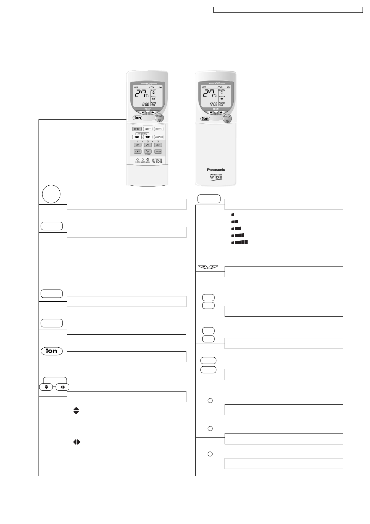
2.1. Remote Control
CS-E15DKDW CU-E15DKD / CS-E1 8DKDW CU-E18DKD / CS-E21DKD S CU-E21DKD
OFF/ON
I
MODE
POWERFUL
QUIET
AIR SWING
Operation OFF / ON
Operation Mode Selection
•
•
•
•
a
HEAT
COOL
DRY
Automatic Operation
Heating Operation
Cooling Operation
Soft Dry Operation
Powerful Mode Operation
Quiet Mode Operation
Ion Mode Operation
Airflow Direction Control
• Vertical Automatic Airflow
Direction Control and Manual
Airflow Direction Control (5
stages of adjustment).
•
Horizontal Automatic Airflow
Direction Control and Manual
Airflow Direction Control (5
stages of adjustment).
FAN SPEED
TEMP
TIMER
ON
OFF
∧
∨
SET
CANCEL
CLOCK
CHECK
RESET
Indoor Fan Speed Selection
• Low
•
•
•
•
•
AUTO
FAN
MediumMedium
Medium+
High
Automatic Fan Speed
Room Temperature Setting
• Increase or decrease set temperature.
(16°C to 30°C)
Timer Setting
• 24-hour, OFF / ON Real Timer Setting.
Time / Timer Setting
• Hours and minutes setting.
Timer Operation Set / Cancel
• ON Timer and OFF Timer setting and
cancellation.
Clock Setting
• Current time setting.
Check Point
• Breakdown self diagnosis function.
Reset Point
• Clear memory data.
3
CS-E15DKDW CU-E15DKD / CS-E1 8DKDW CU-E1 8DKD / CS-E2 1DKDS CU- E21DKD
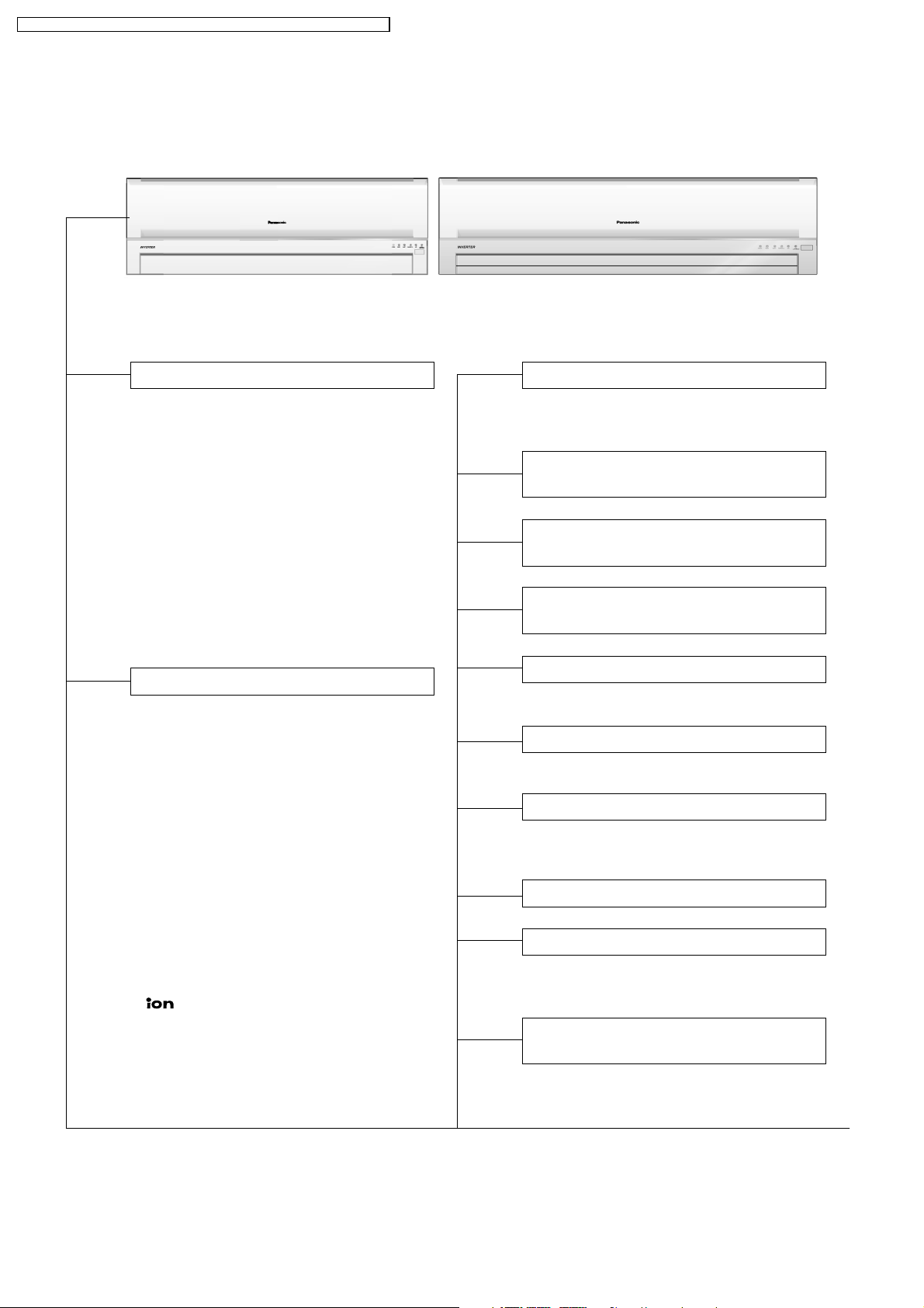
2.2. Indoor Unit
Automatic Operation Switch
• Press for < 5s to run Automatic Operation.
(Used when the remote control cannot be used.)
• Press continuously for 5s and < 8s to run
Forced Cooling Operation.
• Press continuously for 8s and < 11s to
run Forced Heating Operation.
• Press continuously for 11s and < 16s to
change different remote controlling
setting (4 type of transmission code).
• Press continuously for 16s or < 21s to
switch OFF / ON Remote Control
Receiving Sound or H14 Abnormality
Detection Mode.
Operation Indication Lamps (LED)
•
POWER
•
TIMER
•
QUIET
•
POWERFUL
•
SUPER ALLERU-BUSTER ....
•
(Blue) operation.
(Green) ......
(Orange) .... Lights up in Timer
(Orange) .... Lights up in Quiet
(Orange) ... Lights up when
(Green) ............ Lights up in Ionizer
Lights up in operation,
blinks in Automatic
Operation Mode
judging, deice, On
Timer sampling and
Hot Start operation.
Setting.
Blinks in Self
Diagnosis Control.
Mode Operation.
Powerful Mode is
selected.
Mode Operation.
Blinks in Ionizer
error.
Lights up in
Four Operation Modes
• Automatic, Heating, Cooling and Soft Dry
Operation.
Automatic and 5 Manual Indoor
Fan Speeds
Automatic and 5 Manual Vertical
Airflow Directions
Automatic and 5 Manual Horizontal
Airflow Directions
Powerful Mode
• For quick cooling or heating.
Quiet Mode
• To provide quiet operation.
Ionizer Control
• Ionizer control for generate negative ion
in discharge air.
Delay ON Timer and OFF Timer
Automatic Restart Control
• Operation is restarted after power failure
at previous setting mode.
Microcomputer-controlled Room
Temperature Control
4
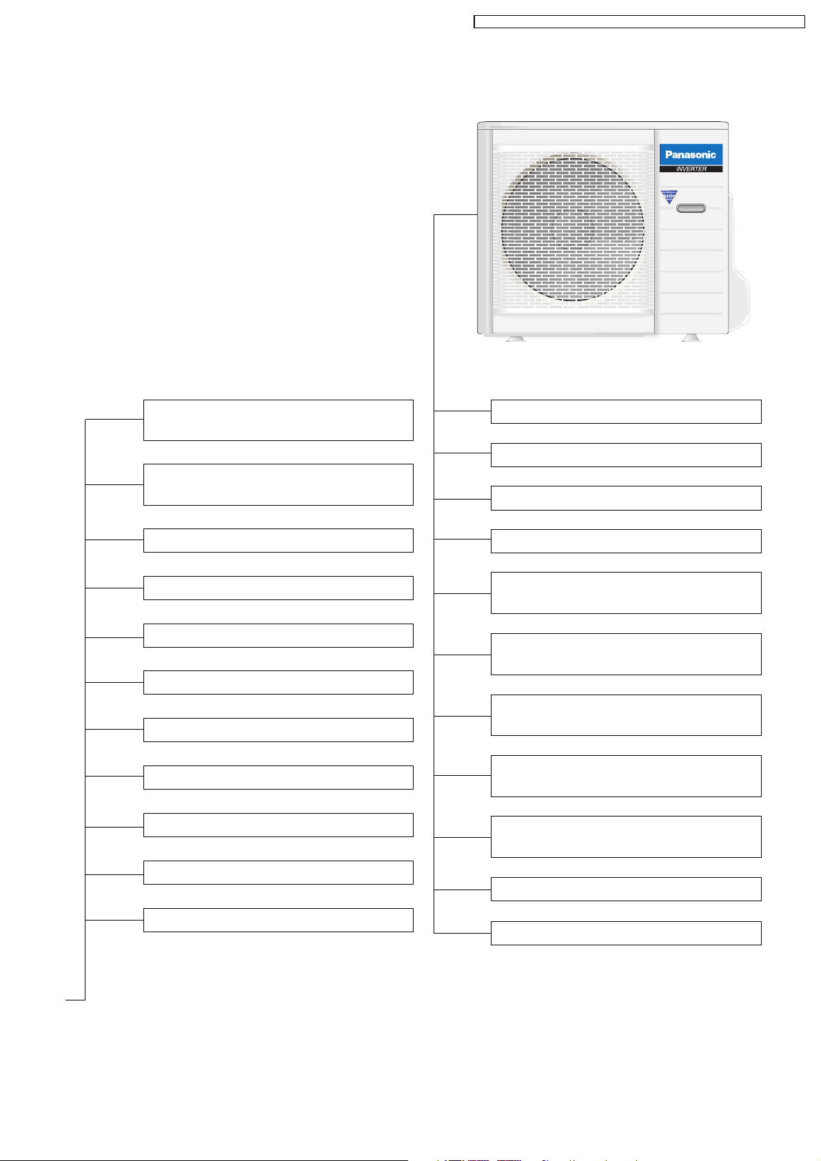
2.3. Outdoor Unit
CS-E15DKDW CU-E15DKD / CS-E1 8DKDW CU-E1 8DKD / CS-E2 1DKDS CU- E21DKD
Breakdown Self Diagnosis
Function
Low Pressure Control
(Gas Leakeage Detection)
Indoor Power Relay Control
Anti-Dew Formation Control
Anti Freezing Control
Anti-Cold Draft Control
Hot Start
Intake Air Temperature Control
Time Delay Safety Control
30 seconds Forced Operation
Overload Protection Control
Total Running Current Control
Compressor Overheating
Prevention Control
IPM (Power Transistor)
Overheating Protection Control
Low Operation Frequency
Protection Control
Mininum Operation Frequency
Protection Control
High Pressure Control
Deodorizing Control
Deice Operation
Outdoor Air Temperature
Control
Standby Control
Deice Operation
5
CS-E15DKDW CU-E15DKD / CS-E1 8DKDW CU-E1 8DKD / CS-E2 1DKDS CU- E21DKD
3 Product Specifications
3.1. CS-E15DKDW CU-E15DKD
Unit CS-E15DKDW CU-E15DKD
Cooling Capacity kW
kcal/h
BTU/h
Heating Capacity kW
kcal/h
BTU/h
Moisture Removal l/h
Pint/h
Power Source (Phase, Voltage, Cycle) ø
V
Hz
Airflow Method OUTLET
INTAKE
4.40 (0.90 - 5.00)
3,780 (770 - 4,300)
15,000 (3,070 - 17,100)
5.50 (0.90 - 7.10)
4,730 (770 - 6,110)
18,800 (3,070 - 24,200)
2.4
(5.1)
Single
220 - 230
50
SIDE VIEW TOP VIEW
Air Volume Lo m3/min (cfm) Cooling; 7.4 (260) —
Heating; 8.8 (310)
Me m3/min (cfm) Cooling; 9.2 (320) —
Heating; 10.3 (360)
Hi m3/min (cfm) Cooling; 11.0 (390) Cooling; 48.5 (1,710)
Heating; 11.8 (420) Heating; 46.8 (1,650)
dB (A) Cooling; High 43, Low 32 Cooling; 46
Heating; High 43, Low 35 Heating; 46
Noise Level
Power level dB Cooling; High 54 Cooling; High 59
Heating; High 54 Heating; High 59
Electrical Data Input Power W Cooling; 1,370 (215 - 1,600)
Heating; 1,570 (245 - 2,250)
Running Current A Cooling; 6.5 - 6.3
Heating; 7.3 - 7.1
EER W/W Cooling; 3.21 (4.19 - 3.13)
BTU/hW Cooling; 10.9 (14.3 - 10.7)
COP W/W Heating; 3.50 (3.67 - 3.16)
BTU/hW Heating; 12.0 (12.5 - 10.8)
Starting Current A 7.3
6
CS-E15DKDW CU-E15DKD / CS-E1 8DKDW CU-E1 8DKD / CS-E2 1DKDS CU- E21DKD
Unit CS-E15DKDW CU-E15DKD
Piping Connection Port
(Flare piping)
Pipe Size
(Flare piping)
Drain
Hose
Power Cord Length
Number of core-wire
Dimensions Height inch (mm) 11 - 1/32 (280) 29 - 17/32 (750)
Net Weight lb (kg) 20 (9) 106 (48)
Compressor Type — Involute scroll
Air Circulation Type Cross-flow Fan Propeller Fan
Heat Exchanger Description Evaporator Condenser
Refrigerant Control Device — Expansion Valve
Refrigeration Oil (c.c) — RB68A (360)
Refrigerant (R410A) kg (oz) — 1.06 (37.4)
Thermostat Electronic Control —
Protection Device Electronic Control Electronic Control
Capillary Tube Flow Rate l/min — —
Air Filter Material
Inner diameter mm 12 —
Length m 0.65 —
Width inch (mm) 31 - 15/32 (799) 34 - 7/16 (875)
Depth inch (mm) 7 - 7/32 (183) 13 - 19/32 (345)
Motor Type — Brushless (4-pole)
Rated Output W — 700
Material ASHT-18 P.P
Motor Type Transistor (8-poles) Transistor (8-poles)
Rate Output W 30 40
Fan Speed Lo (Cool/Heat) rpm 980 / 1,160 —
Me (Cool/Heat) rpm 1,220 / 1,360 —
Hi (Cool/Heat) rpm 1,460 / 1,560 660 / 640
Tube material Copper Copper
Fin material Aluminium (Pre Coat) Aluminium (Blue Coated)
Fin Type Slit Fin Corrugated Fin
Row / Stage (Plate fin configuration, forced draft)
FPI 21 18
Size (W × H × L) mm 610 × 315 × 25.4 871.7 × 711.2 × 22
Length mm — —
Inner Diameter mm — —
Style
inch
inch
inch
inch
G ; Half Union 1/2”
L ; Half Union 1/4”
G (gas side) ; 1/2”
L (liquid side) ; 1/4”
—— —
2/15 1/28
P.P.
Honeycomb
G ; 3-way valve 1/2”
L ; 2-way valve 1/4”
G (gas side) ; 1/2”
L (liquid side) ; 1/4”
—
—
•
Specifications are subjected to change without notice for further improvement.
7

CS-E15DKDW CU-E15DKD / CS-E1 8DKDW CU-E1 8DKD / CS-E2 1DKDS CU- E21DKD
3.2. CS-E18DKDW CU-E18DKD
Unit CS-E18DKDW CU-E18DKD
Cooling Capacity kW
kcal/h
BTU/h
Heating Capacity kW
kcal/h
BTU/h
Moisture Removal l/h
Pint/h
Power Source (Phase, Voltage, Cycle) ø
V
Hz
Airflow Method OUTLET
INTAKE
5.30 (0.90 - 6.00)
4,560 (770 - 5,160)
18,100 (3,070 - 20,500)
6.60 (0.90 - 8.00)
5,680 (770 - 6,880)
22,500 (3,070 - 27,300)
2.9
(6.1)
Single
220 - 230
50
SIDE VIEW TOP VIEW
Air Volume Lo m3/min (cfm) Cooling; 12.3 (430) —
Heating; 13.0 (460)
Me m3/min (cfm) Cooling; 13.9 (490) —
Heating; 14.6 (520)
Hi m3/min (cfm) Cooling; 15.2 (540) 40.0 (1,410)
Heating; 16.7 (590)
dB (A) Cooling; High 44, Low 37 Cooling; 47
Heating; High 44, Low 37 Heating; 47
Noise Level
Power level dB Cooling; High 57 Cooling; High 60
Heating; High 57 Heating; High 60
Electrical Data Input Power W Cooling; 1,650 (215 - 2,050)
Heating; 1,790 (245 - 2,650)
Running Current A Cooling; 7.7 - 7.5
Heating; 8.3 - 8.1
Piping Connection Port
(Flare piping)
EER W/W Cooling; 3.21 (4.19 - 2.93)
BTU/hW Cooling; 11.0 (14.3 - 10.0)
COP W/W Heating; 3.69 (3.67 - 3.02)
BTU/hW Heating; 12.6 (12.5 - 10.3)
Starting Current A 8.3
inch
inch
G ; Half Union 1/2”
L ; Half Union 1/4”
G ; 3-way valve 1/2”
L ; 2-way valve 1/4”
8
CS-E15DKDW CU-E15DKD / CS-E1 8DKDW CU-E1 8DKD / CS-E2 1DKDS CU- E21DKD
Unit CS-E18DKDW CU-E18DKD
Pipe Size
(Flare piping)
Drain
Hose
Power Cord Length
Number of core-wire
Dimensions Height inch (mm) 10 - 13/16 (275) 29 - 17/32 (750)
Net Weight lb (kg) 24 (11) 108 (49)
Compressor Type — Involute scroll
Air Circulation Type Cross-flow Fan Propeller Fan
Heat Exchanger Description Evaporator Condenser
Refrigerant Control Device — Expansion Valve
Refrigeration Oil (c.c) — RB68A (360)
Refrigerant (R410A) kg (oz) — 1.18 (41.7)
Thermostat Electronic Control —
Protection Device Electronic Control Electronic Control
Capillary Tube Flow Rate l/min — —
Air Filter Material
Inner diameter mm 12 —
Length m 0.65 —
Width inch (mm) 39 - 9/32 (998) 34 - 7/16 (875)
Depth inch (mm) 9 - 1/16 (230) 13 - 19/32 (345)
Motor Type — Brushless (4-pole)
Rated Output W — 900
Material ASHT-18 P.P
Motor Type Transistor (8-poles) Transistor (8-poles)
Rate Output W 30 40
Fan Speed Lo (Cool/Heat) rpm 1,170 / 1,240 —
Me (Cool/Heat) rpm 1,330 / 1,395 —
Hi (Cool/Heat) rpm 1,450 / 1,580 660 / 640
Tube material Copper Copper
Fin material Aluminium (Pre Coat) Aluminium (Blue Coated)
Fin Type Slit Fin Corrugated Fin
Row / Stage (Plate fin configuration, forced draft)
FPI 21 16
Size (W × H × L) mm 810 × 315 × 25.4 849.3
Length mm — —
Inner Diameter mm — —
Style
inch
inch
G (gas side) ; 1/2”
L (liquid side) ; 1/4”
—— —
2/15 2/34
P.P.
Honeycomb
G (gas side) ; 1/2”
L (liquid side) ; 1/4”
—
× 714 × 36.4
878
—
•
Specifications are subjected to change without notice for further improvement.
9
CS-E15DKDW CU-E15DKD / CS-E1 8DKDW CU-E1 8DKD / CS-E2 1DKDS CU- E21DKD
3.3. CS-E21DKDS CU-E21DKD
Unit CS-E21DKDS CU-E21DKD
Cooling Capacity kW
kcal/h
BTU/h
Heating Capacity kW
kcal/h
BTU/h
Moisture Removal l/h
Pint/h
Power Source (Phase, Voltage, Cycle) ø
V
Hz
Airflow Method OUTLET
INTAKE
6.30 (0.90 - 7.10)
5,420 (770 - 6,110)
21,500 (3,070 - 24,200)
7.20 (0.90 - 8.50)
6,190 (770 - 7,310)
24,600 (3,070 - 29,000)
3.5
(7.4)
Single
220 - 230
50
SIDE VIEW TOP VIEW
Air Volume Lo m3/min (cfm) Cooling; 12.5 (440) —
Heating; 13.5 (480)
Me m3/min (cfm) Cooling; 14.4 (510) —
Heating; 14.9 (530)
Hi m3/min (cfm) Cooling; 16.2 (570) Cooling; 42.8 (1,510)
Heating; 17.3 (610) Heating; 41.5 (1,460)
dB (A) Cooling; High 45, Low 37 Cooling; 48
Heating; High 45, Low 37 Heating; 49
Noise Level
Power level dB Cooling; High 58 Cooling; High 61
Heating; High 58 Heating; High 62
Electrical Data Input Power W Cooling; 2,210 (215 - 2,540)
Heating; 2,100 (245 - 2,750)
Running Current A Cooling; 10.4 - 9.9
Heating; 9.7 - 9.3
Piping Connection Port
(Flare piping)
EER W/W Cooling; 2.85 (4.19 - 2.80)
BTU/hW Cooling; 9.7 (14.3 - 9.5)
COP W/W Heating; 3.43 (3.67 - 3.09)
BTU/hW Heating; 11.7 (12.5 - 10.5)
Starting Current A 9.7
inch
inch
G ; Half Union 1/2”
L ; Half Union 1/4”
G ; 3-way valve 1/2”
L ; 2-way valve 1/4”
10

CS-E15DKDW CU-E15DKD / CS-E1 8DKDW CU-E1 8DKD / CS-E2 1DKDS CU- E21DKD
Unit CS-E21DKDS CU-E21DKD
Pipe Size
(Flare piping)
Drain
Hose
Power Cord Length
Number of core-wire
Dimensions Height inch (mm) 10 - 13/16 (275) 29 - 17/32 (750)
Net Weight lb (kg) 24 (11) 112 (51)
Compressor Type — Involute scroll
Air Circulation Type Cross-flow Fan Propeller Fan
Heat Exchanger Description Evaporator Condenser
Refrigerant Control Device — Expansion Valve
Refrigeration Oil (c.c) — RB68A (360)
Refrigerant (R410A) kg (oz) — 1.29 (45.5)
Thermostat Electronic Control —
Protection Device Electronic Control Electronic Control
Capillary Tube Flow Rate l/min — —
Air Filter Material
Inner diameter mm 12 —
Length m 0.65 —
Width inch (mm) 39 - 9/32 (998) 34 - 7/16 (875)
Depth inch (mm) 9 - 1/16 (230) 13 - 19/32 (345)
Motor Type — Brushless (4-pole)
Rated Output W — 900
Material ASHT-18 P.P
Motor Type Transistor (8-poles) Transistor (8-poles)
Rate Output W 30 40
Fan Speed Lo (Cool/Heat) rpm 1,170 / 1,270 —
Me (Cool/Heat) rpm 1,355 / 1,400 —
Hi (Cool/Heat) rpm 1,520 / 1,610 700 / 680
Tube material Copper Copper
Fin material Aluminium (Pre Coat) Aluminium (Blue Coated)
Fin Type Slit Fin Corrugated Fin
Row / Stage (Plate fin configuration, forced draft)
FPI 19 18
Size (W × H × L) mm 810 × 315 × 25.4 839.5
Length mm — —
Inner Diameter mm — —
Style
inch
inch
G (gas side) ; 1/2”
L (liquid side) ; 1/4”
—— —
2/15 2/34
P.P.
Honeycomb
G (gas side) ; 1/2”
L (liquid side) ; 1/4”
—
× 714 × 36.4
868
—
•
Specifications are subjected to change without notice for further improvement.
11
CS-E15DKDW CU-E15DKD / CS-E1 8DKDW CU-E1 8DKD / CS-E2 1DKDS CU- E21DKD
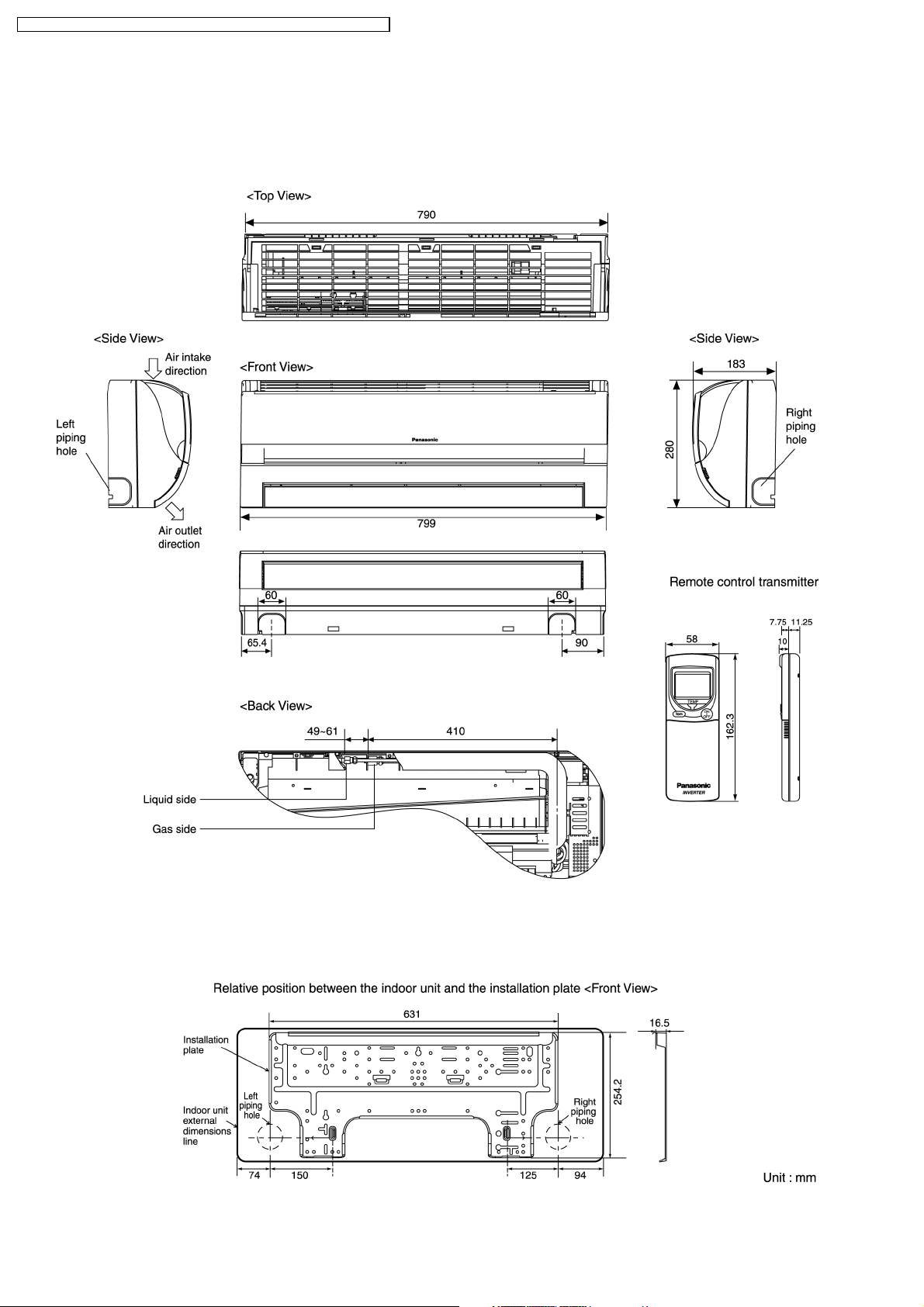
4 Dimensions
4.1. Indoor Unit & Remote Control
4.1.1. CS-E15DKDW
12
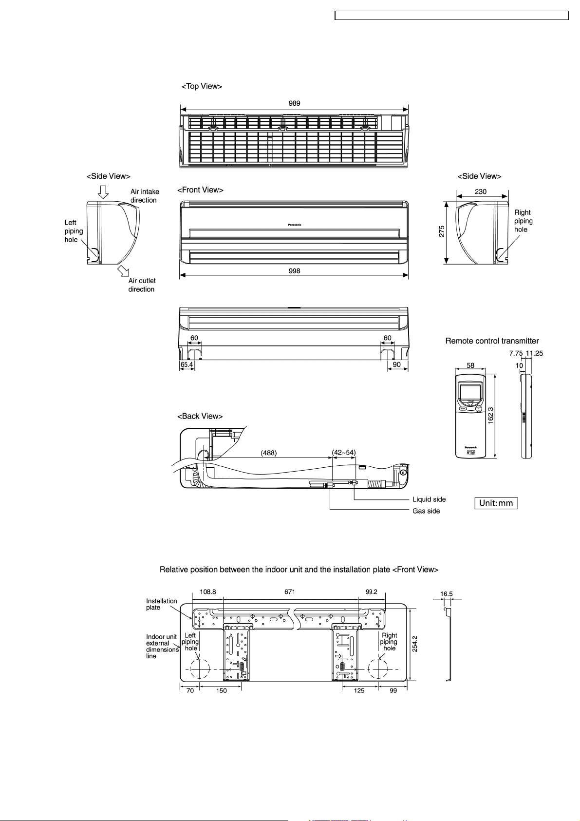
4.1.2. CS-E18DKDW CS-E21DKDS
CS-E15DKDW CU-E15DKD / CS-E1 8DKDW CU-E1 8DKD / CS-E2 1DKDS CU- E21DKD
13
CS-E15DKDW CU-E15DKD / CS-E1 8DKDW CU-E1 8DKD / CS-E2 1DKDS CU- E21DKD
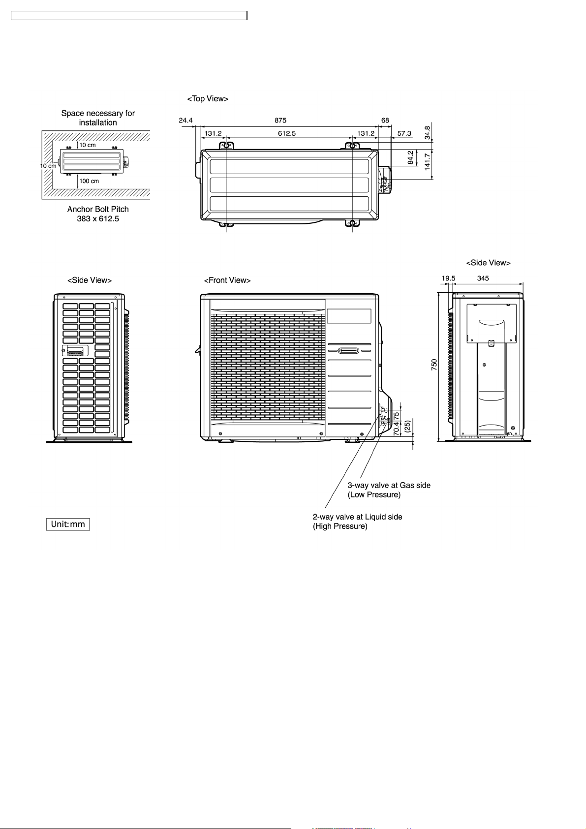
4.2. Outdoor Unit
4.2.1. CU-E15DKD CU-E18DKD CU-E21DKD
14
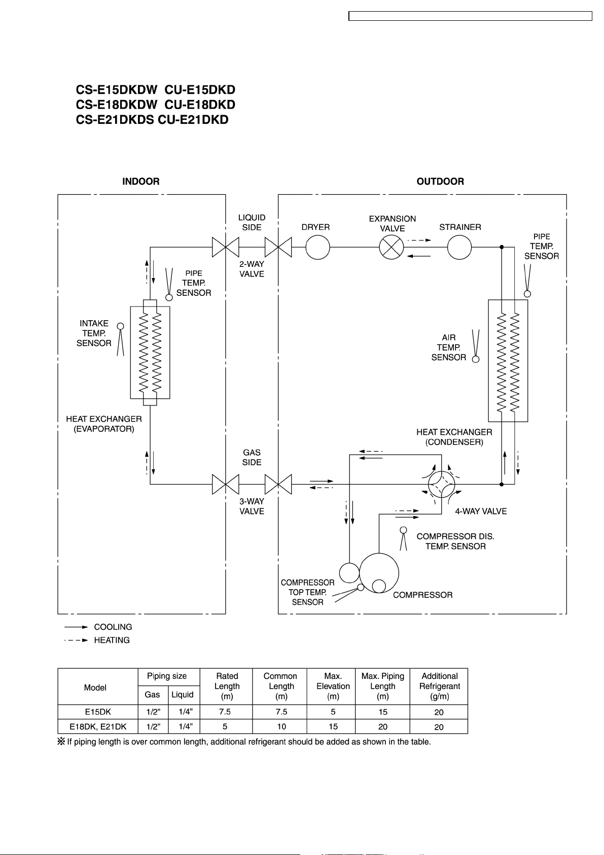
5 Refrigeration Cycle Diagram
CS-E15DKDW CU-E15DKD / CS-E1 8DKDW CU-E1 8DKD / CS-E2 1DKDS CU- E21DKD
15
CS-E15DKDW CU-E15DKD / CS-E1 8DKDW CU-E1 8DKD / CS-E2 1DKDS CU- E21DKD
6 Block Diagram
16
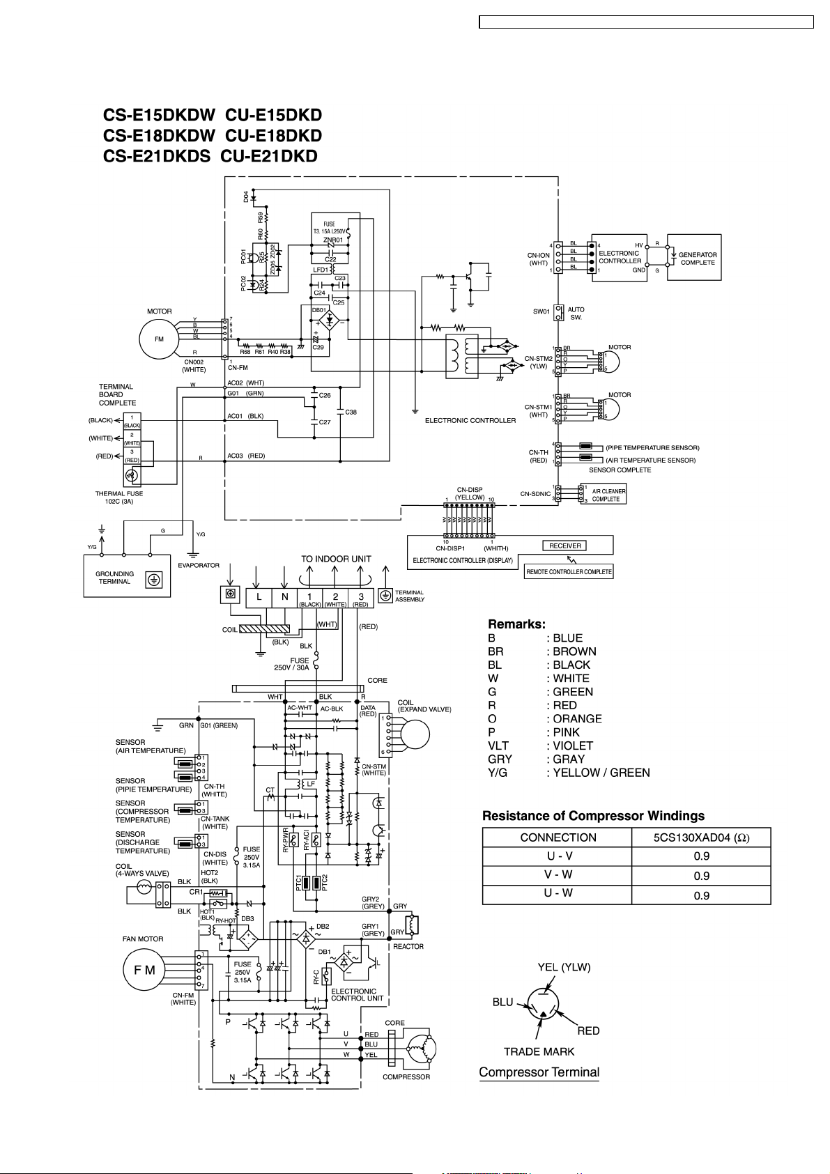
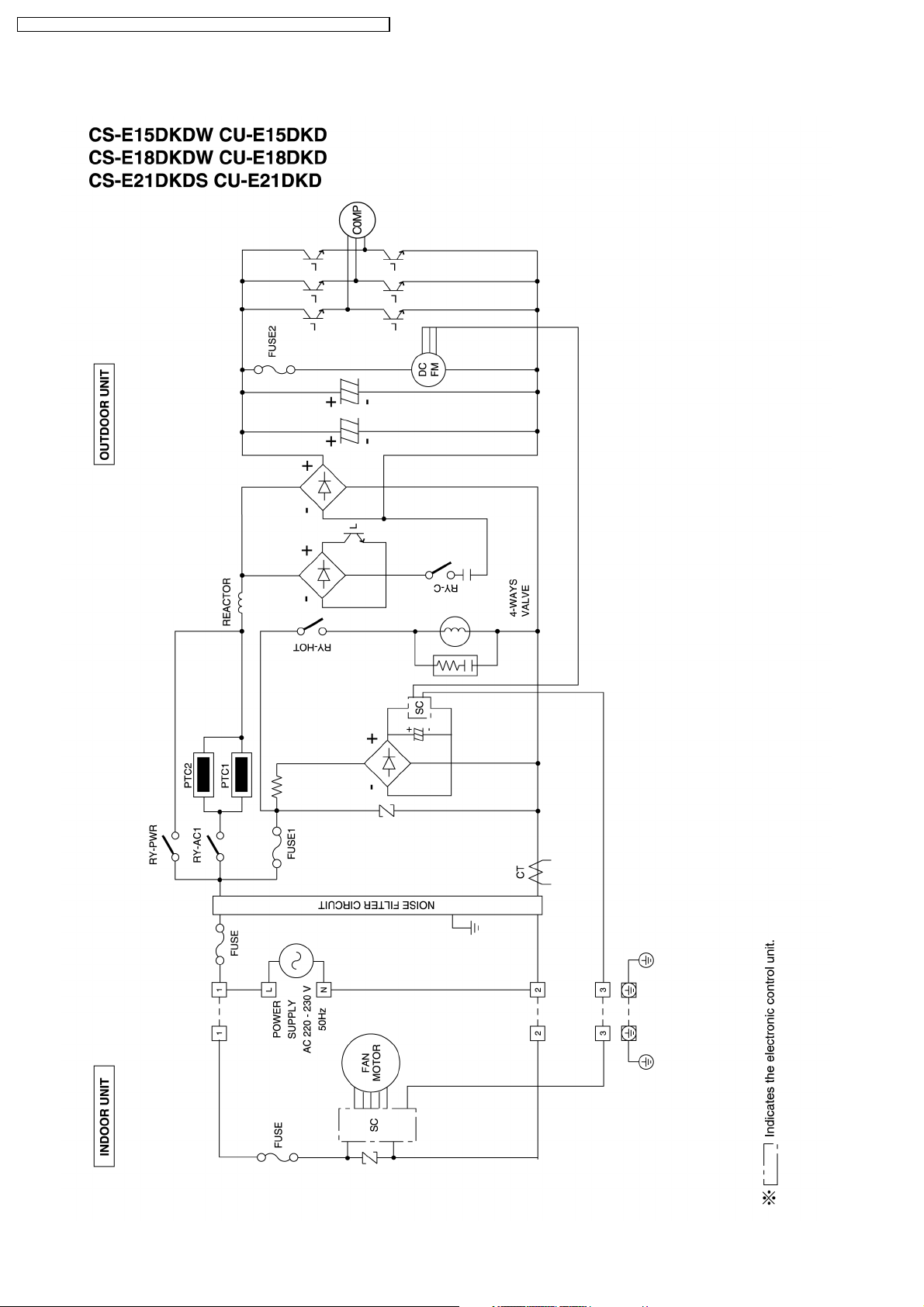
7 Wiring Diagram
CS-E15DKDW CU-E15DKD / CS-E1 8DKDW CU-E1 8DKD / CS-E2 1DKDS CU- E21DKD
17
CS-E15DKDW CU-E15DKD / CS-E1 8DKDW CU-E1 8DKD / CS-E2 1DKDS CU- E21DKD
8 Operation Details
8.1. Basic Function
Inverter control, which equipped with a microcomputer in determining the most suitable operating mode as time passes,
automatically adjusts output power for maximum comfort always. In order to achieve the suitable operating mode, the
microcomputer maintains the set temperature by measuring the temperature of the environment and performing temperature
shifting. The compressor at outdoor unit is operating following the frequency instructed by the microcomputer at indoor unit that
judging the condition according to internal setting temperature and intake air temperature.
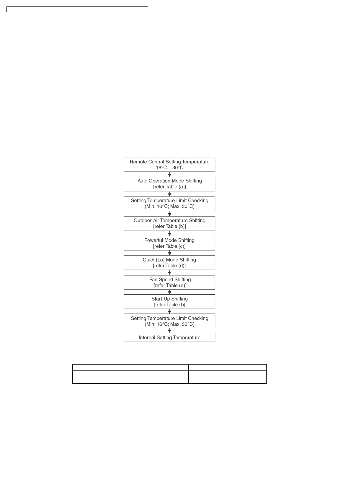
8.1.1. Internal Setting Temperature
Once the operation starts, remote control setting temperature will be taken as base value for temperature shifting processes.
These shifting processes are depending on the air conditioner settings and the operation environment. The final shifted value
will be used as internal setting temperature and it is updated continuously whenever the electrical power is supplied to the unit.
Table (a): Auto Operation Mode Setting
Cooling/Soft Dry→Heating -2.0
Heating→Cooling/Soft Dry +2.0
Mode Shift: Temperature Shift (°C)
18
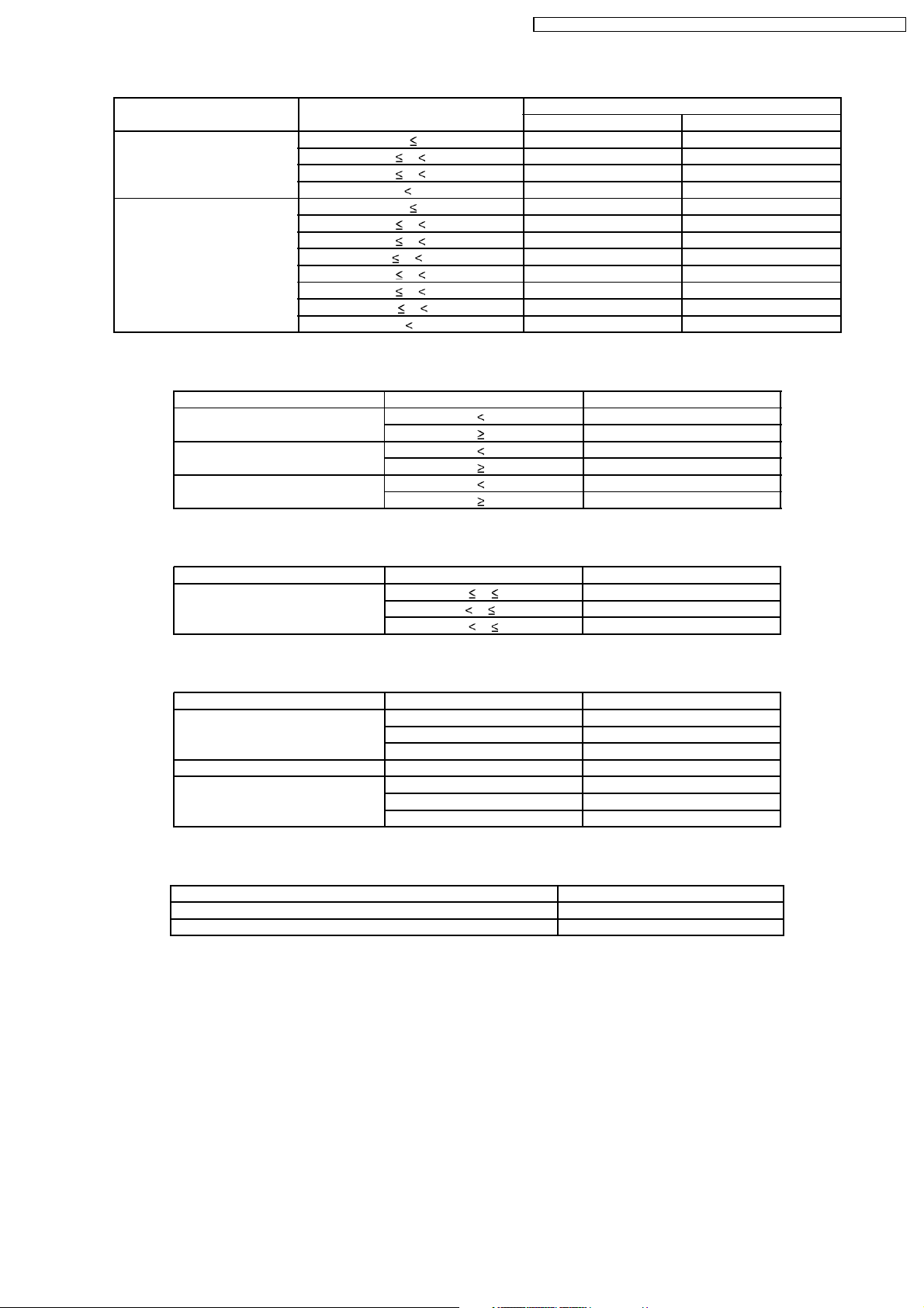
Table (b): Outdoor Air Temperature Shifting
Mode: Outdoor Temperature, X (°C): Temperature Shift (°C)
Cooling/Soft Dry 38 X 1.50 2.00
Heating 21 X -2.25 -1.50
Table (c): Powerful Mode Shifting
Mode: Period, X (min): Temperature Shift (°C)
Cooling X 20 -2.0
Soft Dry X 20 -1.0
Heating X 20 +3.5
CS-E15DKDW CU-E15DKD / CS-E1 8DKDW CU-E1 8DKD / CS-E2 1DKDS CU- E21DKD
Manual Operation Auto Operation
30 X 38 1.25 1.25
23 X 30 1.25 1.25
X 23 1.75 1.75
17 X 21 -1.75 -1.00
13 X 17 -0.75 0.00
9 X 13 0.25 0.25
5 X 9 1.25 1.00
1 X 5 0.75 1.00
-3 X 1 1.50 1.00
X -3 1.50 1.00
X 20 0.0
X 20 0.0
X 20 +3.25
Table (d): Quiet (Lo) Mode Shifting
Mode: Period, X (min): Temperature Shift (°C)
Cooling, Soft Dry 20 min X 50 min -3.0
Table (e): Fan Speed Shifting
Mode: Fan Speed: Temperature Shift (°C)
Cooling Lo -0.25
Soft Dry All +0.25
Heating Lo +1.50
Table (f): Start-Up Shifting
Mode within 60 Minutes from Start-up: Temperature Shift (°C)
Cooling/Soft Dry -1.0
Heating +2.0
50 min X 110 min -4.0
110 min X 440 min -5.0
Me-, Me, Me+, Auto 0.00
Hi +0.25
Me-, Me, Me+, Auto +0.75
Hi +0.75
19
CS-E15DKDW CU-E15DKD / CS-E1 8DKDW CU-E1 8DKD / CS-E2 1DKDS CU- E21DKD
8.1.2. Compressor Operation Frequency
Intake Air Temperature - Internal Setting Temperature (°C) Freq. H
Zone Cooling & Soft Dry Heating Cooling Soft Dry Heating Remark
1 -2.0 1.5 1 1 1
2 -1.5 1.0 1 1 1
3 -1.0 0.5 14 8 11
4 -0.5 0.0 20 8 15
5 0.0 -0.5 27 8 22
6 0.5 -1.0 35 11 27
7 1.0 -1.5 43 11 36
8 1.5 -2.0 46 11 39 Fc, Fh
9 2.0 -2.5 46 11 39 Fc, Fh
10 2.5 -3.0 46 11 39 Fc, Fh
11 Nil -3.5 Nil Nil 39 Fh
12 Nil -4.0 Nil Nil 39 Fh
Operating Frequency Calculation Formula:
CompHz = Freq. A × Freq. H + Freq. C
Example Calculation:
Model No.: E18DK
Operation Mode: Cooling
When Intake Air Temperature - Internal setting Temperature:
1.5°C
CompHz = Freq. A × Freq. H + Freq. C
= 1.53 × 46 + 2.5
= 72 Hz (It cuts down less than a decimal point)
Cooling & Soft Dry E18DK E21DK
Freq. A Freq. C Freq. A Freq. C
Low Load (Freq. H 9) 1.2 5.0 1.7 7.0
High Load (Freq. H > 10) 1.53 2.5 2.0 4.0
Heating E18DK E21DK
Freq. A Freq. C Freq. A Freq. C
Low Load (Freq. H 11) 1.6 8.0 1.9 7.0
High Load (Freq. H > 12) 2.2 1.0 2.35 1.0
Freq. Range E18DK E21DK
Cooling Fc 72 96
Operation Range 12 ~ 86 12 ~ 102
Heating Fh 86 92
Operation Range 14 ~ 128 14 ~ 128
Remarks:
When Freq. H is equal to 46 (Cooling), 39 (Heating) or above, the Comp. may run at the freq. higher than Fc or Fh up to max.
freq. operation.
Best Amenity Control
Every 90s (Cooling), 120s (Heating) maintain same zone Freq. H + 1 until Fc (46), Fh (39).
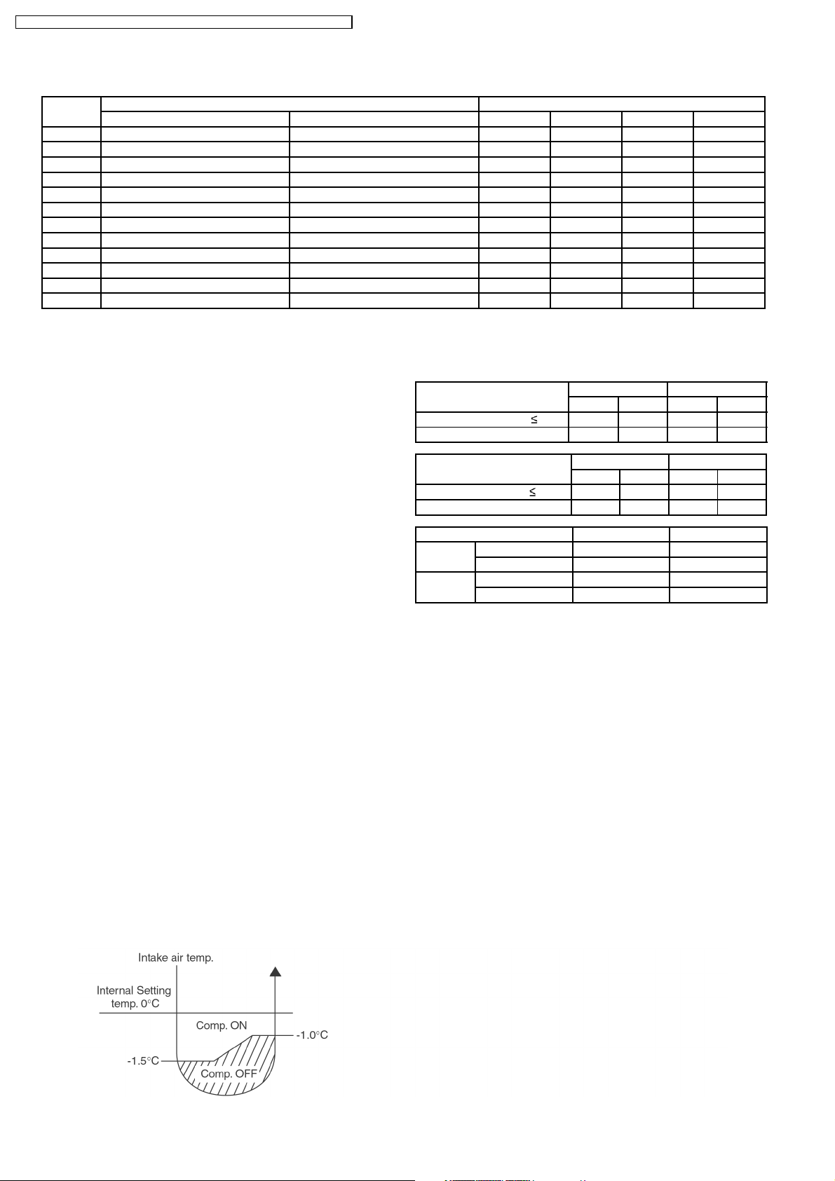
8.1.3. Cooling Operation
8.1.3.1. Thermostat control
Compressor is OFF when Intake Air Temperature - Internal Setting Temperature < -1.5°C.
•
Compressor is ON after waiting for 3 minutes, if the Intake Air Temperature - Internal Setting Temperature > Compressor OFF
•
point +0.5°C.
20
CS-E15DKDW CU-E15DKD / CS-E1 8DKDW CU-E1 8DKD / CS-E2 1DKDS CU- E21DKD
8.1.4. Soft Dry Operation
8.1.4.1. Thermostat control
Compressor is OFF when Intake Air Temperature - Internal Setting Temperature < -2.5°C.
•
Compressor is ON after waiting for 3 minutes, if the Intake Air Temperature - Internal Setting Temperature > Compressor OFF
•
point.
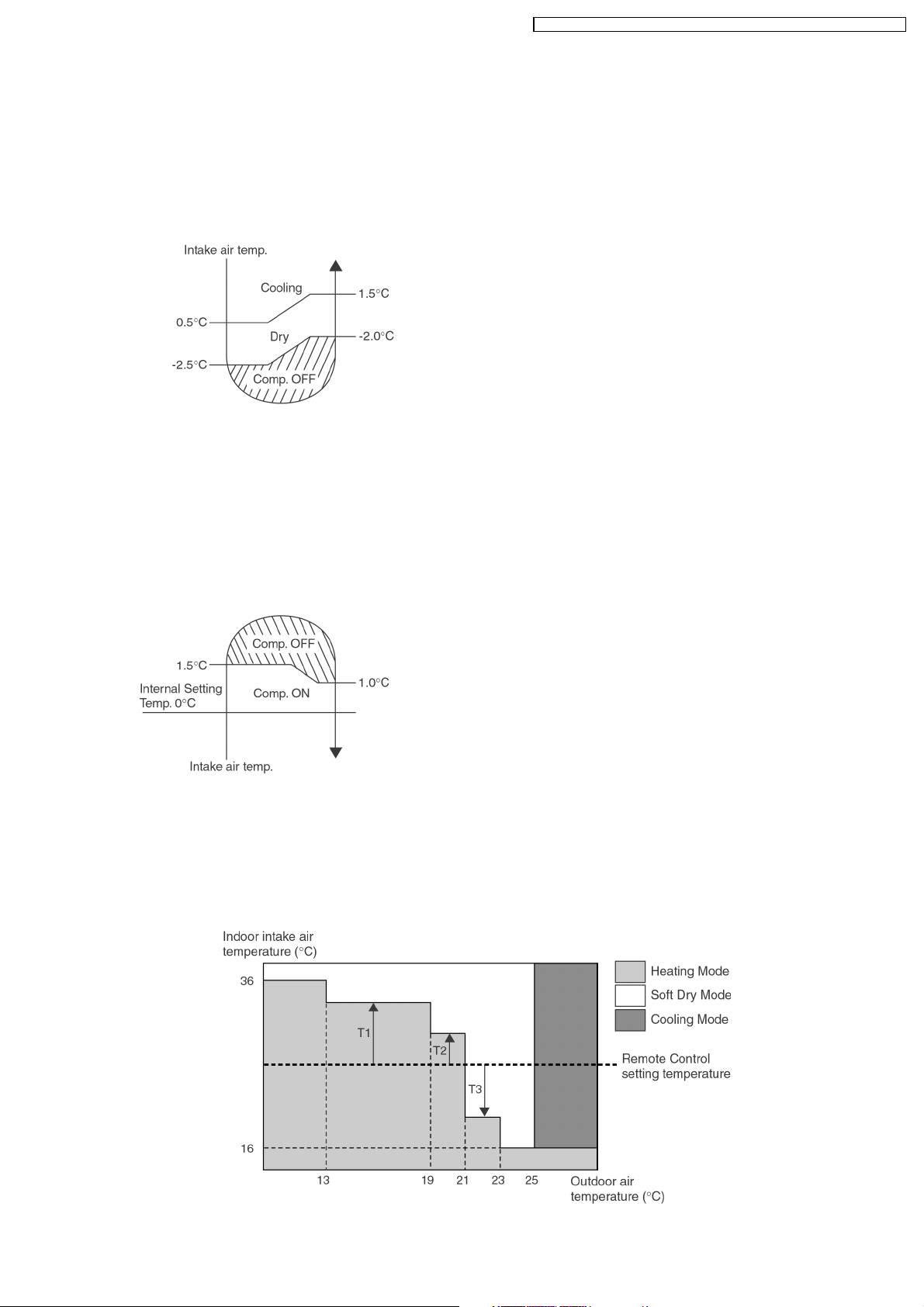
8.1.5. Heating Operation
8.1.5.1. Thermostat control
Compressor is OFF when Intake Air Temperature - Internal Setting > +1.5°C.
•
Compressor is ON after waiting for 3 minutes, if the Intake Air Temperature - Internal Setting Temperature < Compressor OFF
•
point -0.5°C.
8.1.6. Automatic Operation
This mode can be set using remote control and the operation is decided by remote control setting temperature, indoor intake air
temperature and outdoor air temperature.
During operation mode judgment, indoor fan motor (with speed of Lo-) and outdoor fan motor are running for 30 seconds to detect
the indoor intake and outdoor air temperature. The operation mode is decided based on below chart.
21
CS-E15DKDW CU-E15DKD / CS-E1 8DKDW CU-E1 8DKD / CS-E2 1DKDS CU- E21DKD
Values of T1, T2, and T3 depend on remote control setting temperature, as shown in below table. After the adjustment of T1, T2
and T3 values, the operation mode for that particular environment and remote control setting is judged and performed, based on
the above operation mode chart, every 30 minutes.
Remote Control Setting Temperature (°C) T1 T2 T3
16 ~ 18 +10 +8 -5
19 ~ 22 +8 +7 -7
23 ~ 26 +7 +6 -7
27 ~ 30 +6 +5 -8
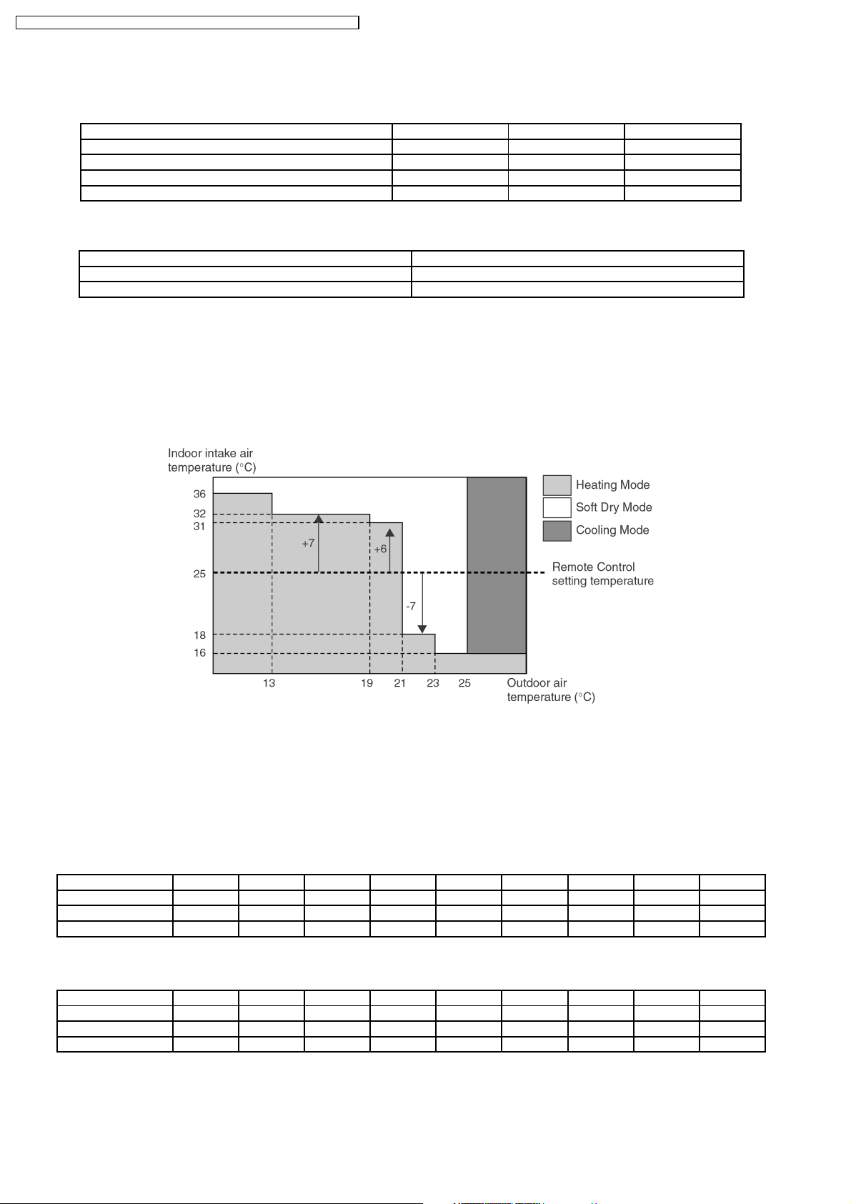
There is a temperature shifting on T1, T2, and T3 if the operation mode judged is changed from Cooling/Soft Dry to Heating or vice
verse.
Operation Mode change from Temperature shifts (°C)
Cooling/Soft Dry→Heating -2
Heating→Cooling/Soft Dry +2
Example of operation mode chart adjustment:
From the above table, if remote control setting temperature = 25,
T1 = 25 + 7 = 32; T2 = 25 + 6 = 31; T3 = 25 - 7 = 18
The operation mode chart for this example is as shown in below figure and the operation mode to be performed will depend on
indoor intake air temperature and outdoor air temperature at the time when the judgment is made.
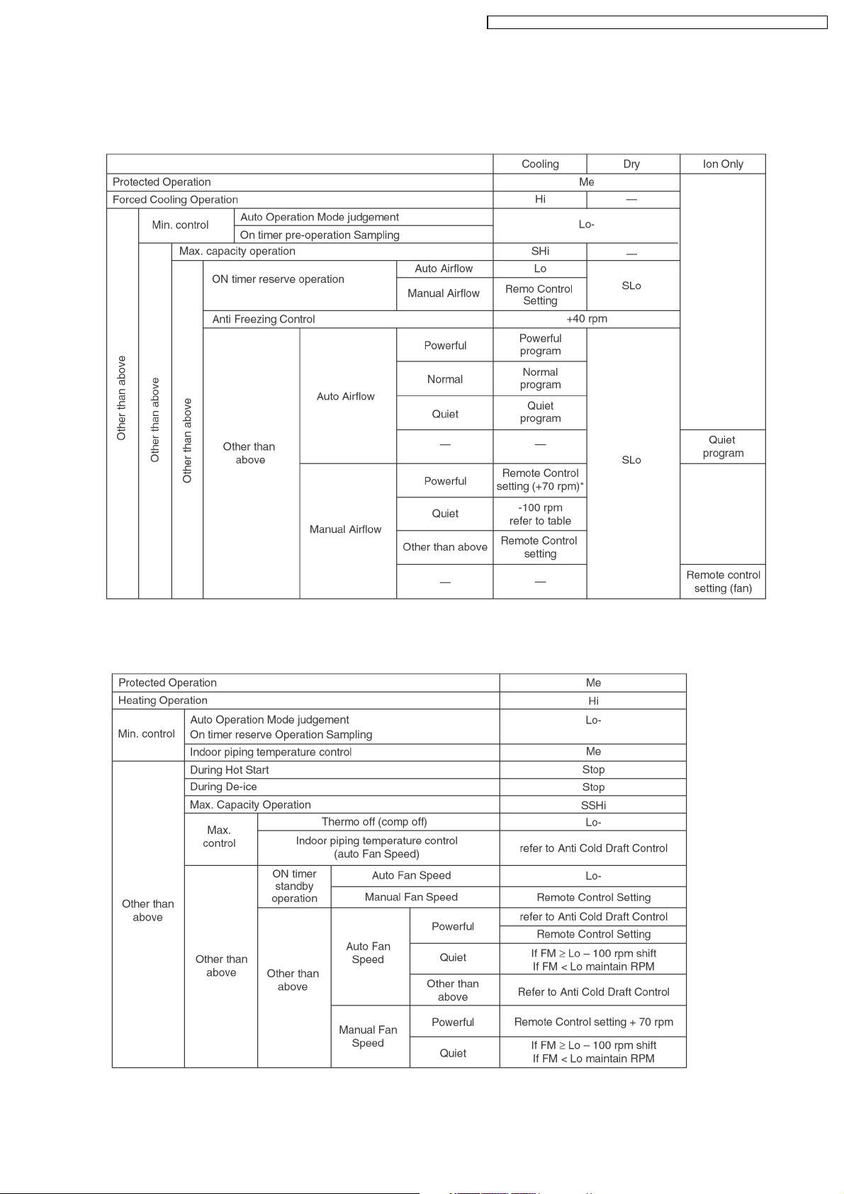
8.1.7. Indoor Fan Motor Operation
A. Basic Rotation Speed (rpm)
Required rotation speed for fan is set to respond to the remote control setting (10 rpm unit)
•
[Cooling, Dry, Fan]
Remote Control — O O O O O — — —
Tab (rpm) SHI Hi Me+ Me Me- Lo Lo- SLo SSLo
E18DK 1530 1440 1360 1290 1220 1150 850 760 630
E21DK 1610 1520 1420 1330 1240 1150 890 800 630
[Heating]
Remote Control — O O O O O — — —
Tab (rpm) SSHI SHi Me+ Me Me- Lo Lo- SLo SSLo
E18DK 1590 1560 1480 1410 1340 1270 850 400 300
E21DK 1640 1610 1520 1440 1350 1270 890 400 300
22
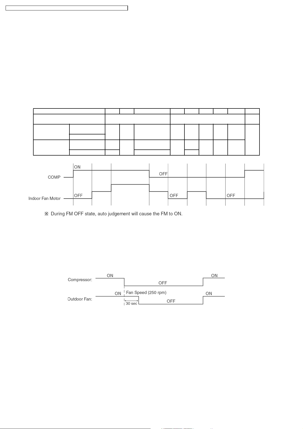
B. Indoor Fan Control
i. Indoor fan control operation outline
1. Cooling / Dry
CS-E15DKDW CU-E15DKD / CS-E1 8DKDW CU-E1 8DKD / CS-E2 1DKDS CU- E21DKD
2. Heating
23
CS-E15DKDW CU-E15DKD / CS-E1 8DKDW CU-E1 8DKD / CS-E2 1DKDS CU- E21DKD
ii. Auto Fan Speed
1. Cooling
2. Heating
Note:
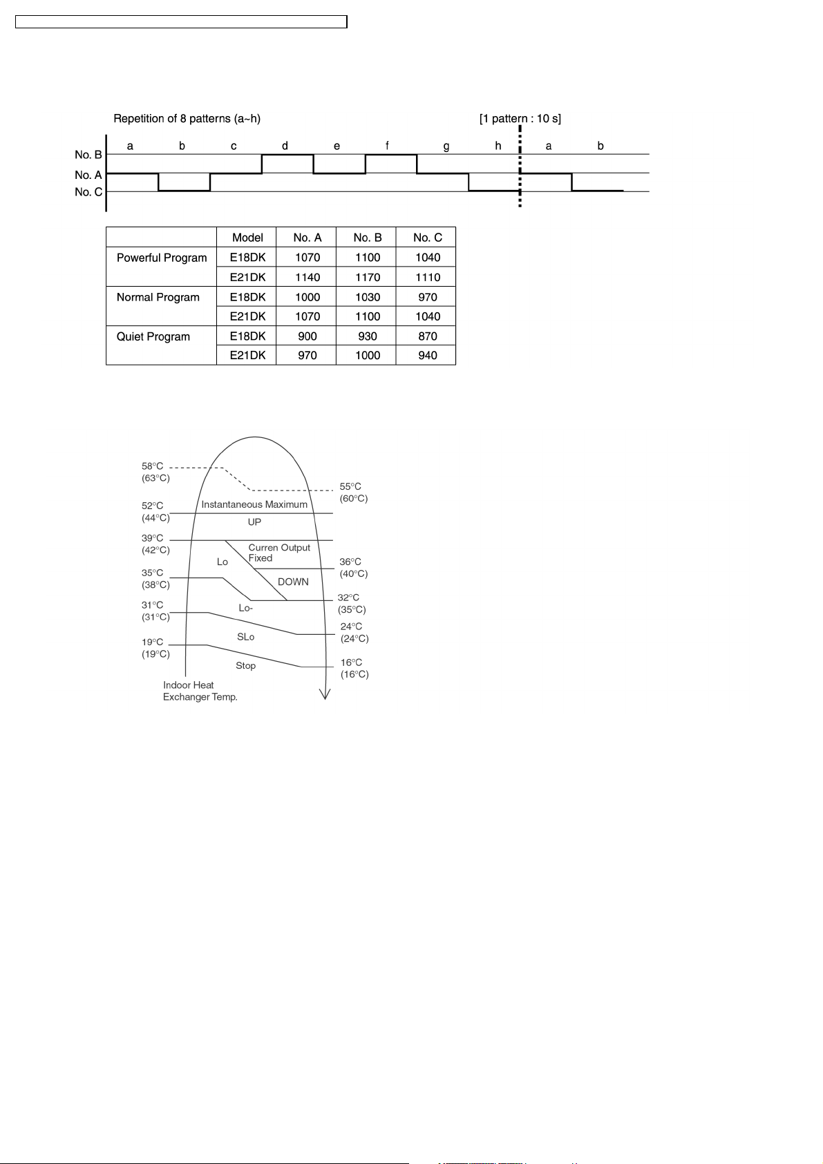
a. UP:
If move from Lo, the fan speed will be shifted to Maximum 1520 rpm (E21DK), 1480 rpm (E18DK).
•
If move from Maximum, the fan speed no change.
•
In up zone, 10 rpm is added for every 10s until Maximum 1520 rpm (E21DK ), 1480 rpm (E18DK).
•
b. DOWN:
The fan speed will be decreased one step every 10 sec. until Minimum 1270 rpm.
•
c. Current Output Fixed:
Maintain at present fan speed.
•
d. Instantaneous Maximum:
Fan speed will be increased to maximum auto fan speed.
•
e. Temperature in ( ) is for Powerful Mode operation.
24

CS-E15DKDW CU-E15DKD / CS-E1 8DKDW CU-E1 8DKD / CS-E2 1DKDS CU- E21DKD
iii. Max Capacity Condition
a) During Cooling operation, if all to the following condition is fulfilled, the indoor fan speed is set to Shi.
1. Indoor intake temperature
24°C.
2. Operation frequency 72 Hz (E18DK), 95 Hz (E21DK) & above.
3. Remote Control setting temperature 16°C.
4. Remote Control setting fan speed Hi.
5. Outdoor temperature
6. Operation start
30°C.
within 30 minutes.
* If any of above conditions is not valid, the condition is ended.
b) During Heating operation, if all to the following condition is fulfilled, the indoor fan speed is set to SSHi.
1. Indoor intake temperature is 17°C or above and less than 23°C.
2. Operation frequency 86 Hz (E18DK), 93 Hz (E21DK) & above.
3. Remote Control setting temperature 30°C.
4. Remote Control setting fan speed Hi.
5. Outdoor temperature < 4°C.
6. Operation start
2 hours.
* If any of above conditions is not valid, the condition is ended.
C. Fan Motor Control
i. Motor specification
High voltage PWM Motor
ii. Feedba ck Control
1. Rotation speed feedback
Immediately after the fan started, rpm is checked and duty is added, and feedba ck control is performed.
iii. Abnormal Detection
1. Condition **Step out signal input
2. Control * Fan stop
3. Return * Restart after 5s
Feedback rotation speed is more than 2550 rpm or below 50 rpm.
However, 10s after fan start, rotation abnormality is not detected.
However, in case the fan is stopped by the above conditions within 25s after fan has started, and happened
continuously for 7 times, restart will not be performed.
Indoor fan motor lock abnormal (H19)
→
iv. Restart Prohibition Control
Prohibit to restart within 5s after fan stop.
(except when power is ON)
25
CS-E15DKDW CU-E15DKD / CS-E1 8DKDW CU-E1 8DKD / CS-E2 1DKDS CU- E21DKD
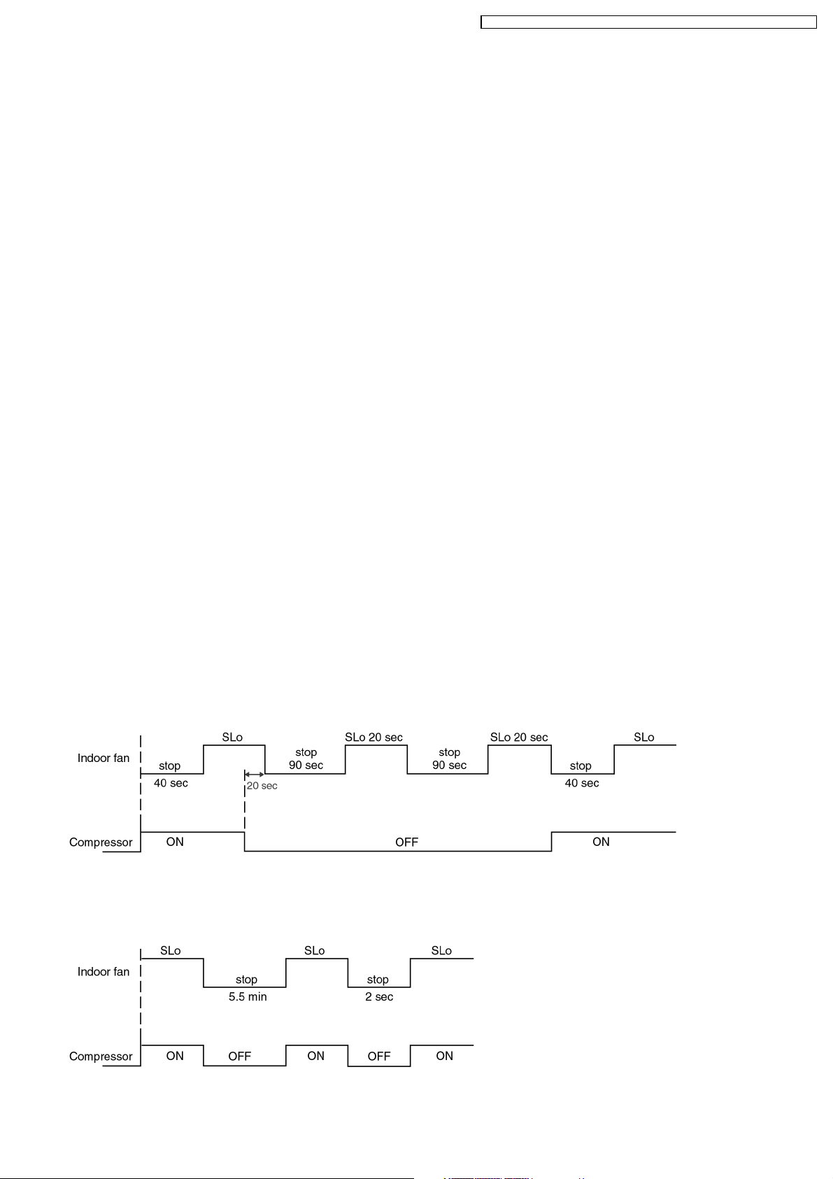
D. Deodorizing Control
i. Control condition
Control at cooling/dry operation and auto fan speed.
No Deodorizing Control is performed during ON timer standby operation and during Anti-freezing control prevention.
ii. Operation
The odor status is arranged as below and it is shifted as follow.
* When COMP is ON 1→2→3
(Shift to 4 when COMP is OFF)
* When COMP is OFF 4→5→4
(Shift to 1 when COMP is ON)
* Start from 4 if the Thermostat is OFF during the start operation.
Odor Status 1 2 3 4 5 4 5 4.5.4... 1
Status Shift
according to COMP
Status Shift
according
to time (s) Dry zone ON
Fan Speed
Cooling
zone
Cooling
zone
Dry zone OFF SLo OFF
40 50 — 20 90 20 90 .......
OFF
ON OFF ON
Auto Fan Speed
SLo
SLo
←→
5
OFF
SLo OFF .......
8.1.8. Outdoor Fan Motor Operation
Outdoor fan motor is operated with 15 fan speed. It starts when compressor starts operation and it stops 30 seconds after
compressor stops operation.
26
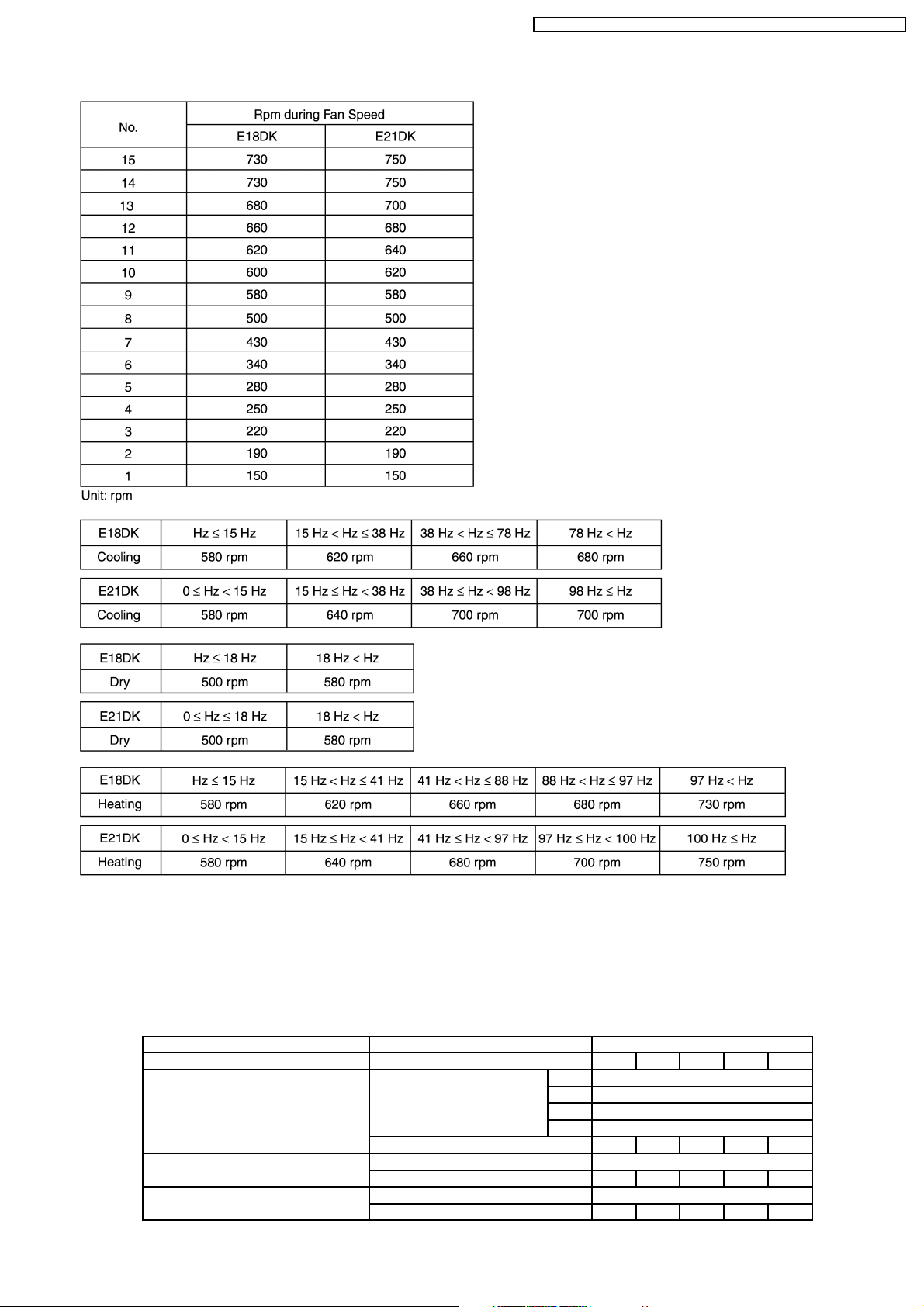
Basic Rotation Speed
CS-E15DKDW CU-E15DKD / CS-E1 8DKDW CU-E1 8DKD / CS-E2 1DKDS CU- E21DKD
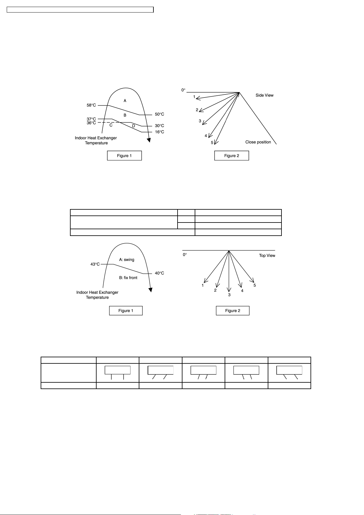
8.1.9. Airflow Direction
1. There are two types of airflow, vertical airflow (directed by horizontal vane) and horizontal airflow (directed by vertical vanes).
2. Control of airflow direction can be automatic (angles of direction is determined by operation mode, heat exchan ger temperature
and intake air temperature) and manual (angles of direction can be adjusted using remote control).
Vertical Airflow
Operation Mode Airflow Direction Vane Angle (°)
1 2 3 4 5
Heating Auto with Heat Exchanger A 16
B 50
Temperature C 8
D 8
Manual 8 17 33 49 60
Cooling, Soft Dry and Ion Auto 8~38
Manual 8 17 25 33 38
Mode Judgment in Auto Auto 8
Manual 8 17 25 33 38
27
CS-E15DKDW CU-E15DKD / CS-E1 8DKDW CU-E1 8DKD / CS-E2 1DKDS CU- E21DKD
1. Automatic vertical airflow direction can be set using remote control; the vane swings up and down within the angles as stated
above. For heating mode operation, the angle of the vane depends on the indoor heat exchanger temperature as Figure 1
below. When the air conditioner is stopped using remote control, the vane will shift to close position.
2. Manual vertical airflow direction can be set using remote control; the angles of the vane are as stated above and the
positions of the vane are as Figure 2 below. When the air conditioner is stopped using remote control, the vane will shift to
close position .
Horizontal Airflow
1. Automatic horizontal airflow direction can be set using remote control; the vane swings left and right within the angles as
stated below. For heating mode operation, the angle of the vane depends on the indoor heat exchanger temperature as
Figure 1 below.
Operation Mode Vane Angle (°)
Heating, with heat exchanger temperature A 68 ~ 112
B 90
Cooling, Soft Dry and Ion 68 ~ 112
2. Manual horizontal airflow direction can be set using remote control; the angles of the vane are as stated below and the
positions of the vane are as Figure 2 above.
Pattern 1 2 3 4 5
Airflow Direction
Patterns at Remote
Control
Vane Angle (°) 90 68 79 101 112
28
CS-E15DKDW CU-E15DKD / CS-E1 8DKDW CU-E1 8DKD / CS-E2 1DKDS CU- E21DKD
8.1.10. Quiet operation (Cooling Mode/Cooling area of Dry Mode)
A. Purpose
To provide quiet cooling operation compare to normal operation.
B. Control condition
a. Quiet operation start condition
When “quiet” button at remote control is pressed.
•
Quiet LED illuminates.
b. Quiet operation stop condition
1. When one of the following conditions is satisfied, quiet operation stops:
a. Powerful button is pressed.
b. Stop by OFF/ON switch.
c. Timer “off” activates.
d. Quiet button is pressed again.
2. When quiet operation is stopped, operation is shifted to normal operation with previous setting.
3. When fan speed is changed, quiet operation is shifted to quiet operation of the new fan speed.
4. When operation mode is changed, quiet operation is shifted to quiet operation of the new mode.
5. During quiet operation, if timer “on” activates, quiet operation maintains.
6. After off, when on back, quiet operation is not memorised.
D. Control contents
1. Fan speed is changed from normal setting to quiet setting of respective fan speed.
This is to reduce sound of Hi, Me, Lo for 3dB.
2. Fan speed for quiet operation is -100 rpm from setting fan speed.
8.1.10.1. Quiet operation under Soft Dry operation (Dry area at Dry Mode)
Automatic Fan Speed (Dry operation)
Manual Fan Speed (Dry operation)
29

CS-E15DKDW CU-E15DKD / CS-E1 8DKDW CU-E1 8DKD / CS-E2 1DKDS CU- E21DKD
8.1.10.2. Quiet operation (Heating)
A. Purpose
To provide quiet heating operation compare to normal operation.
B. Control condition
a. Quiet operation start condition
When “quiet” button at remote control is pressed.
•
Quiet LED illuminates.
b. Quiet operation stop condition
1. When one of the following conditions is satisfied, quiet operation stops:
a. Powerful button is pressed.
b. Stop by OFF/ON switch.
c. Timer “off” activates.
d. Quiet button is pressed again.
2. When quiet operation is stopped, operation is shifted to normal operation with previous setting.
3. When fan speed is changed, quiet operation is shifted to quiet operation of the new fan speed.
4. When operation mode is changed, quiet operation is shifted to quiet operation of the new mode, except fan only mode.
5. During quiet operation, if timer “on” activates, quiet operation maintains.
6. After off, when on back, quiet operation is not memorised.
C. Control contents
a. Fan Speed manual
1. Fan speed is changed from normal setting to quiet setting of respective fan speed.
This is to reduce sound of Hi, Me, Lo for 3dB.
2. Fan speed for quiet operation is -100 rpm from setting fan speed.
3. Fan Speed Auto
•
If FM
Lo
-100 rpm reduce from normal Heating Auto Fan Speed
•
If FM
Lo
maintain RPM
Indoor FM RPM depends on pipe temp sensor of indoor heat exchanger.
30
 Loading...