

Panasonic CS-E21CKE, CS-E18CKE, CU-E21CKE, CU-E18CKE User Manual
Order No. MAC0308013C2
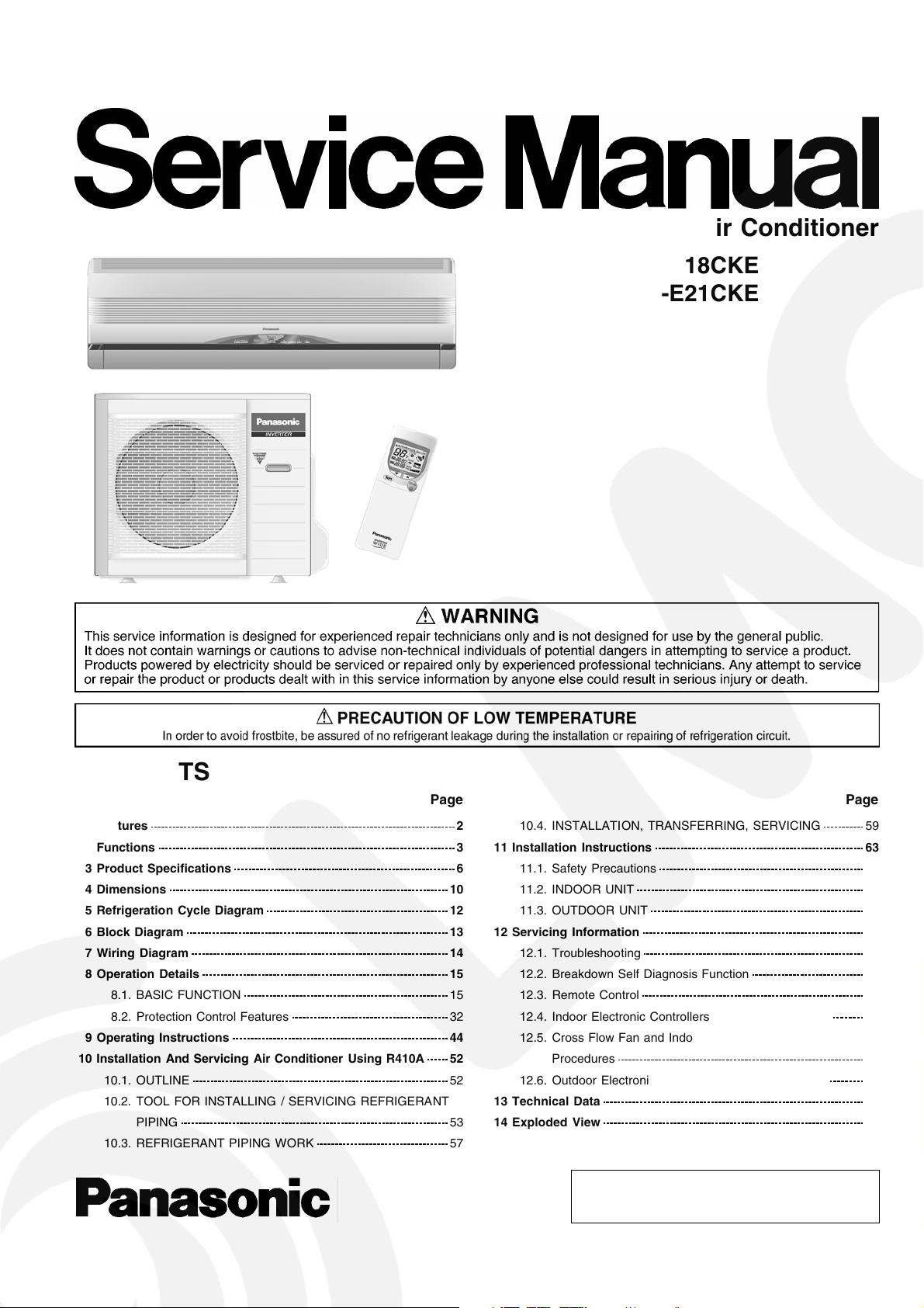
Room Air Conditioner
CS-E18CKE CU-E18CKE
CS-E21CKE CU-E21CKE
CONTENTS
Page Page
1 Features 2
2 Functions
3 Product Specifications
4 Dimensions
5 Refrigeration Cycle Diagram
6 Block Diagram
7 Wiring Diagram
8 Operation Details
8.1. BASIC FUNCTION
8.2. Protection Control Features
9 Operating Instructions
10 Installation And Servicing Air Conditioner Using R410A
10.1. OUTLINE
10.2. TOOL FOR INSTALLING / SERVICING REFRIGERANT
PIPING
10.3. REFRIGERANT PIPING WORK
10
12
13
14
15
15
32
44
52
52
53
57
3
6
10.4. INSTALLATION, TRANSFERRING, SERVICING 59
11 Installation Instructions
11.1. Safety Precautions
11.2. INDOOR UNIT
11.3. OUTDOOR UNIT
12 Servicing Information
12.1. Troubleshooting
12.2. Breakdown Self Diagnosis Function
12.3. Remote Control
12.4. Indoor Electronic Controllers Removal Procedures
12.5. Cross Flow Fan and Indoor Fan Motor Removal
Procedures
12.6. Outdoor Electronic Controller Removal Procedure
13 Technical Data
14 Exploded View
© 2003 Matsushita Industrial Corp. Sdn. Bhd.
(11969-T). All rights reserved. Unauthorized copying
and distribution is a violation of law.
63
63
66
69
72
72
74
76
77
78
80
81
84
15 Replacement Parts List 85
16 Exploded View
17 Replacement Parts List
18 Electronic Circuit Diagram
18.1. REMOTE CONTROL
86
87
88
98
1 Features
18.2. PRINT PATTERNIN DOOR UNIT PRINTED CIRCUIT
BOARD
18.3. PRINT PATTERNO UTDOOR UNIT PRINTED CIRCUIT
BOARD VIEW
99
100
Product
•
− Microcomputer-controlled compressor operating
frequency
− Vertical and Horizontal Airflow Directions
− Five modes of operation selection
− Powerful Mode operation
− Delay ON Timer and OFF Timer
− Remote Control with illuminable buttons
− Power Monitor Display LED
− Catechin Air Purifying Filter
− Triple Deodorizing Filter
− Ionizer Mode Operation
− Quiet Mode Operation
Serviceability
•
− Washable Front Panel
− Breakdown Self Diagnosis function
Environmental Protection
•
− Non-ozone depletio n substances refrigerant (R410A)
Quality Improvement
•
− Gas leakage detection
− Deice operation
− Auto restart control
2
2 Functions
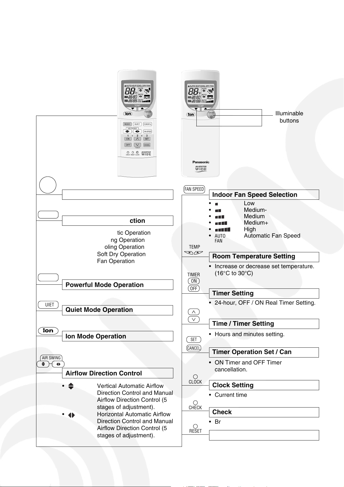
Remote Control
OFF/ON
I
MODE
POWERFUL
QUIET
Operation OFF / ON
Operation Mode Selection
•
a
HEAT
•
•
COOL
DRY
•
•
FAN
Powerful Mode Operation
Quiet Mode Operation
Automatic Operation
Heating Operation
Cooling Operation
Soft Dry Operation
Fan Operation
FAN SPEED
TEMP
TIMER
ON
OFF
∧
∨
Illuminable
buttons
Indoor Fan Speed Selection
• Low
•
Medium-
• Medium
•
•
•
AUTO
FAN
Medium+
High
Automatic Fan Speed
Room Temperature Setting
• Increase or decrease set temperature.
(16°C to 30°C)
Timer Setting
• 24-hour, OFF / ON Real Timer Setting.
Time / Timer Setting
AIR SWING
Ion Mode Operation
Airflow Direction Control
• Vertical Automatic Airflow
Direction Control and Manual
Airflow Direction Control (5
stages of adjustment).
•
Horizontal Automatic Airflow
Direction Control and Manual
Airflow Direction Control (5
stages of adjustment).
SET
CANCEL
Timer Operation Set / Cancel
• ON Timer and OFF Timer setting and
cancellation.
• Hours and minutes setting.
CLOCK
Clock Setting
• Current time setting.
CHECK
Check Point
• Breakdown self diagnosis function.
RESET
Reset Point
• Clear memory data.
3
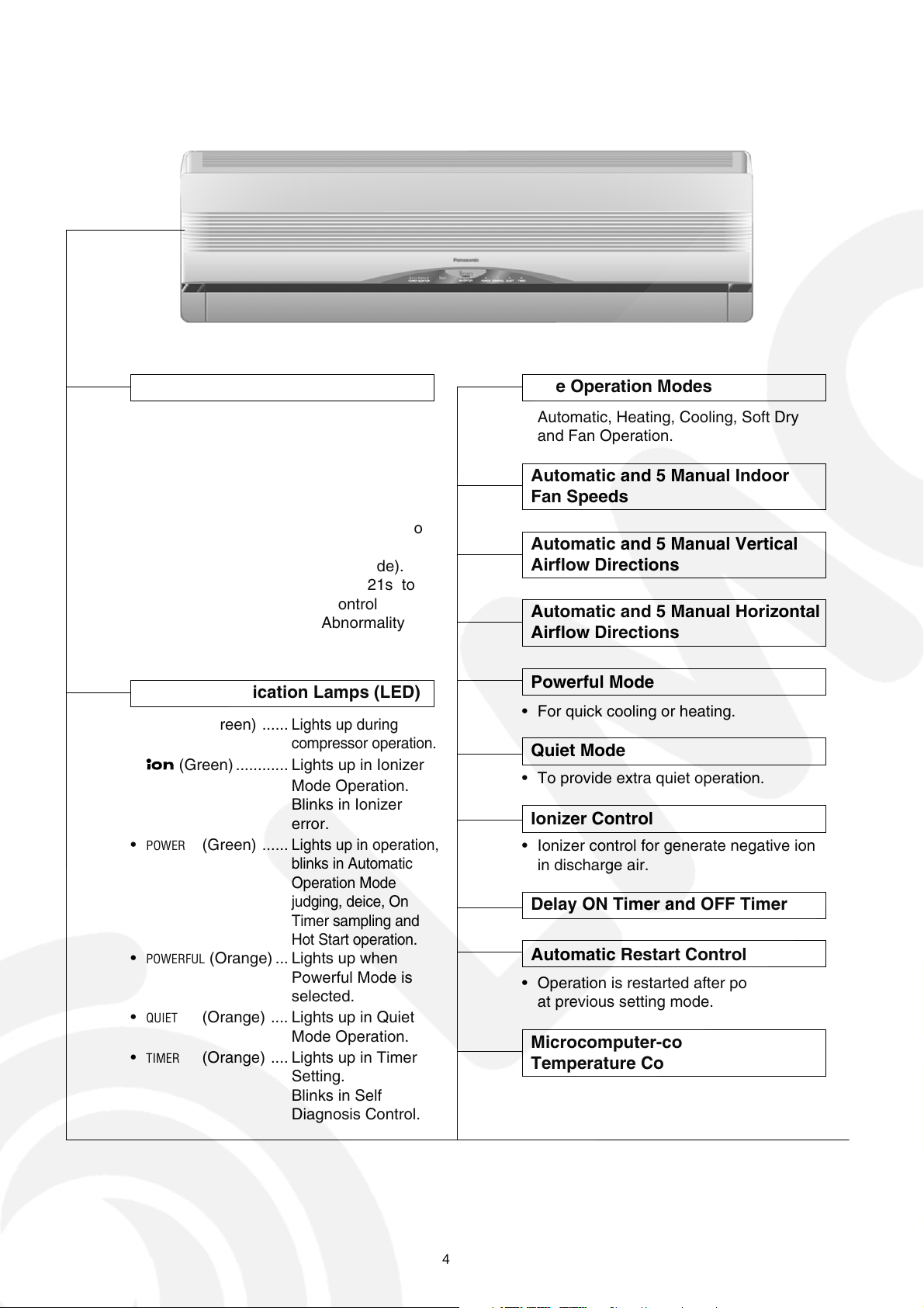
Indoor Unit
Automatic Operation Switch
• Press for < 5s to run Automatic Operation.
(Used when the remote control cannot be used.)
• Press continuously for 5s and < 8s to run
Forced Cooling Operation.
• Press continuously for 8s and < 11s to
run Forced Heating Operation.
• Press continuously for 11s and < 16s to
change different remote controlling
setting (4 type of transmission code).
• Press continuously for 16s or < 21s to
switch OFF / ON Remote Control
Receiving Sound or H14 Abnormality
Detection Mode.
Operation Indication Lamps (LED)
POWER
•
MONITOR
• (Green) ............ Lights up in Ionizer
•
POWER
•
POWERFUL
•
QUIET
•
TIMER
(Green) ......
(Green) ......
(Orange) ... Lights up when
(Orange) .... Lights up in Quiet
(Orange) .... Lights up in Timer
Lights up during
compressor operation.
Mode Operation.
Blinks in Ionizer
error.
Lights up in operation,
blinks in Automatic
Operation Mode
judging, deice, On
Timer sampling and
Hot Start operation.
Powerful Mode is
selected.
Mode Operation.
Setting.
Blinks in Self
Diagnosis Control.
Five Operation Modes
• Automatic, Heating, Cooling, Soft Dry
and Fan Operation.
Automatic and 5 Manual Indoor
Fan Speeds
Automatic and 5 Manual Vertical
Airflow Directions
Automatic and 5 Manual Horizontal
Airflow Directions
Powerful Mode
• For quick cooling or heating.
Quiet Mode
• To provide extra quiet operation.
Ionizer Control
• Ionizer control for generate negative ion
in discharge air.
Delay ON Timer and OFF Timer
Automatic Restart Control
• Operation is restarted after power failure
at previous setting mode.
Microcomputer-controlled Room
Temperature Control
4
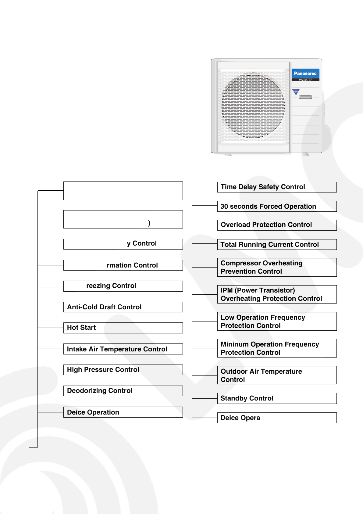
Outdoor Unit
Breakdown Self Diagnosis
Function
Low Pressure Control
(Gas Leakeage Detection)
Indoor Power Relay Control
Anti-Dew Formation Control
Anti Freezing Control
Anti-Cold Draft Control
Hot Start
Intake Air Temperature Control
Time Delay Safety Control
30 seconds Forced Operation
Overload Protection Control
Total Running Current Control
Compressor Overheating
Prevention Control
IPM (Power Transistor)
Overheating Protection Control
Low Operation Frequency
Protection Control
Mininum Operation Frequency
Protection Control
High Pressure Control
Deodorizing Control
Deice Operation
Outdoor Air Temperature
Control
Standby Control
Deice Operation
5
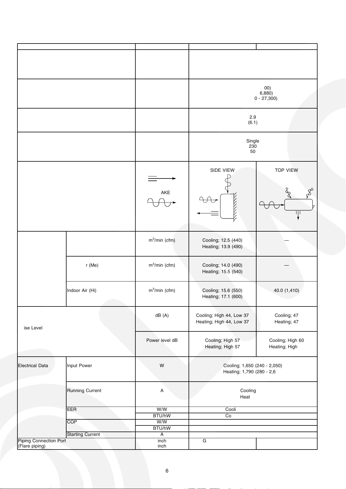
3 Product Specifications
Unit CS-E18CKE CU-E18CKE
Cooling Capacity kW
kcal/h
BTU/h
Heating Capacity kW
kcal/h
BTU/h
Moisture Removal l/h
Pint/h
Power Source Phase
V
Cycle
Airflow Method OUTLET
INTAKE
5.30 (0.90 - 6.00)
4,560 (770 - 5,160)
18,100 (3,070 - 20,500)
6.60 (0.90 - 8.00)
5,680 (770 - 6,880)
22,500 (3,070 - 27,300)
2.9
(6.1)
Single
230
50
SIDE VIEW TOP VIEW
Air Volume Indoor Air (Lo) m3/min (cfm) Cooling; 12.5 (440) —
Heating; 13.9 (490)
Indoor Air (Me) m3/min (cfm) Cooling; 14.0 (490) —
Heating; 15.5 (540)
Indoor Air (Hi) m3/min (cfm) Cooling; 15.6 (550) 40.0 (1,410)
Heating; 17.1 (600)
dB (A) Cooling; High 44, Low 37 Cooling; 47
Heating; High 44, Low 37 Heating; 47
Noise Level
Power level dB Cooling; High 57 Cooling; High 60
Heating; High 57 Heating; High 60
Electrical Data Input Power W Cooling; 1,650 (240 - 2,050)
Heating; 1,790 (280 - 2,650)
Running Current A Cooling; 7.4
Heating; 8.0
Piping Connection Port
(Flare piping)
EER W/W Cooling; 3.21 (3.75 - 2.93)
BTU/hW Cooling; 11.0 (12.8 - 10.0)
COP W/W Heating; 3.69 (3.21 - 3.02)
BTU/hW Heating; 12.6 (11.0 - 10.3)
Starting Current A 8.0
inch
inch
G ; Half Union 1/2”
L ; Half Union 1/4”
G ; 3-way valve 1/2”
L ; 2-way valve 1/4”
6
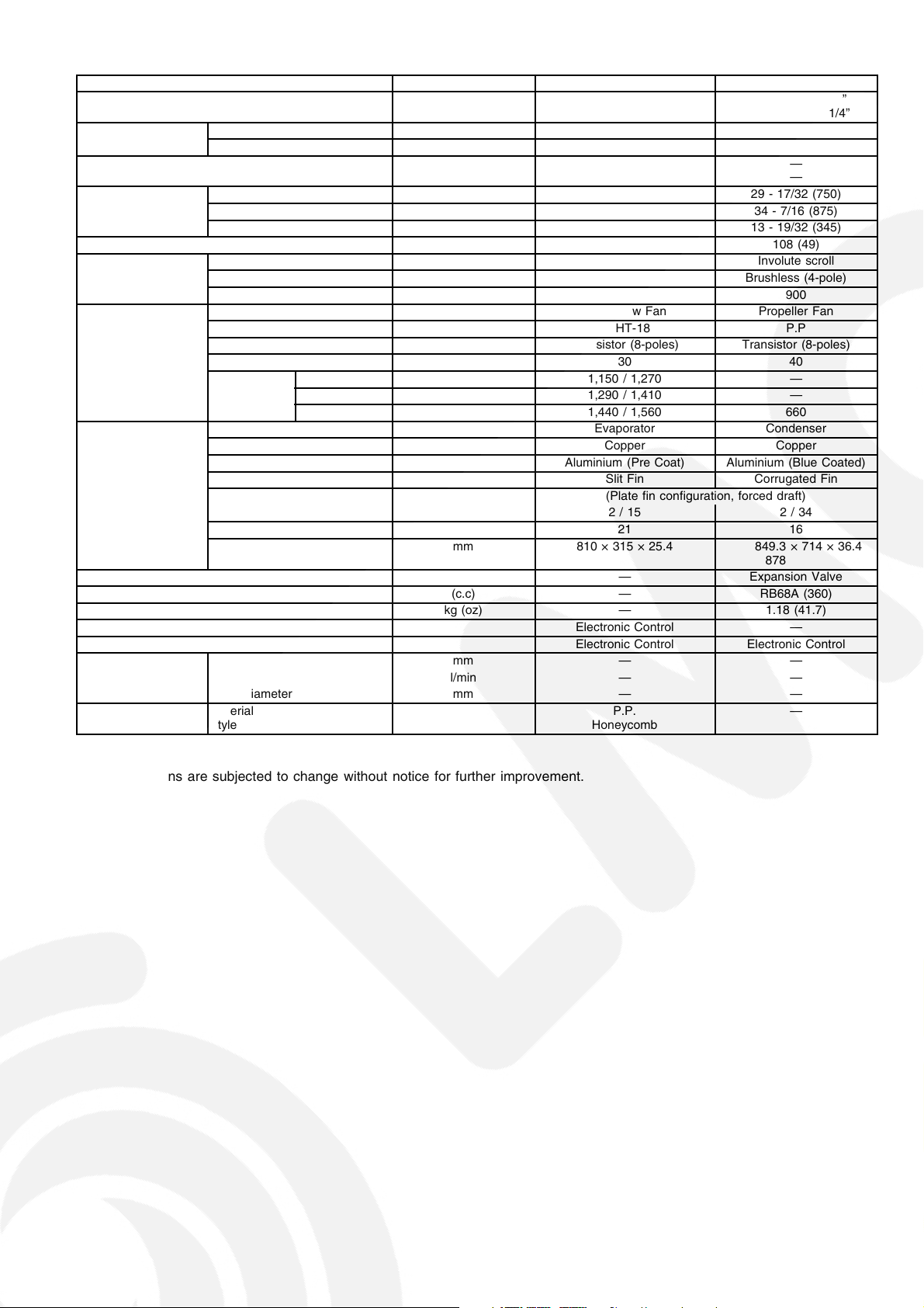
Unit CS-E18CKE CU-E18CKE
Pipe Size
(Flare piping)
Drain
Hose
Power Cord Length
Number of core-wire
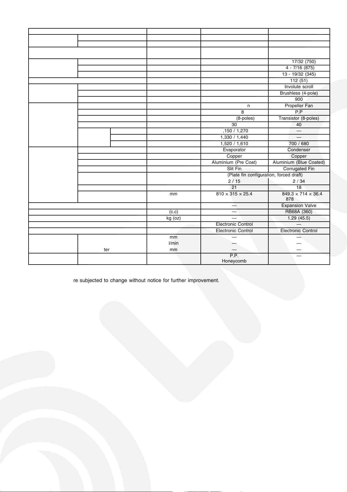
Dimensions Height inch (mm) 10 - 13/16 (275) 29 - 17/32 (750)
Net Weight lb (kg) 24 (11) 108 (49)
Compressor Type — Involute scroll
Air Circulation Type Cross-flow Fan Propeller Fan
Heat Exchanger Description Evaporator Condenser
Refrigerant Control Device — Expansion Valve
Refrigeration Oil (c.c) — RB68A (360)
Refrigerant (R410A) kg (oz) — 1.18 (41.7)
Thermostat Electronic Control —
Protection Device Electronic Control Electronic Control
Capillary Tube Flow Rate l/min — —
Air Filter Material
Inner diameter mm 12 —
Length m 0.65 —
Width inch (mm) 39 - 9/32 (998) 34 - 7/16 (875)
Depth inch (mm) 8 - 9/32 (210) 13 - 19/32 (345)
Motor Type — Brushless (4-pole)
Rated Output W — 900
Material ASHT-18 P.P
Motor Type Transistor (8-poles) Transistor (8-poles)
Rate Output W 30 40
Fan Speed Lo (Cool/Heat) rpm 1,150 / 1,270 —
Me (Cool/Heat) rpm 1,290 / 1,410 —
Hi (Cool/Heat) rpm 1,440 / 1,560 660
Tube material Copper Copper
Fin material Aluminium (Pre Coat) Aluminium (Blue Coated)
Fin Type Slit Fin Corrugated Fin
Row / Stage (Plate fin configuration, forced draft)
FPI 21 16
Size (W × H × L) mm 810 × 315 × 25.4 849.3
Length mm — —
Inner Diameter mm — —
Style
inch
inch
G (gas side) ; 1/2”
L (liquid side) ; 1/4”
2.1 m
3 core wires × 1.5 mm
2/15 2/34
P.P.
Honeycomb
G (gas side) ; 1/2”
L (liquid side) ; 1/4”
2
—
—
× 714 × 36.4
878
—
•
Specifications are subjected to change without notice for further improvement.
7
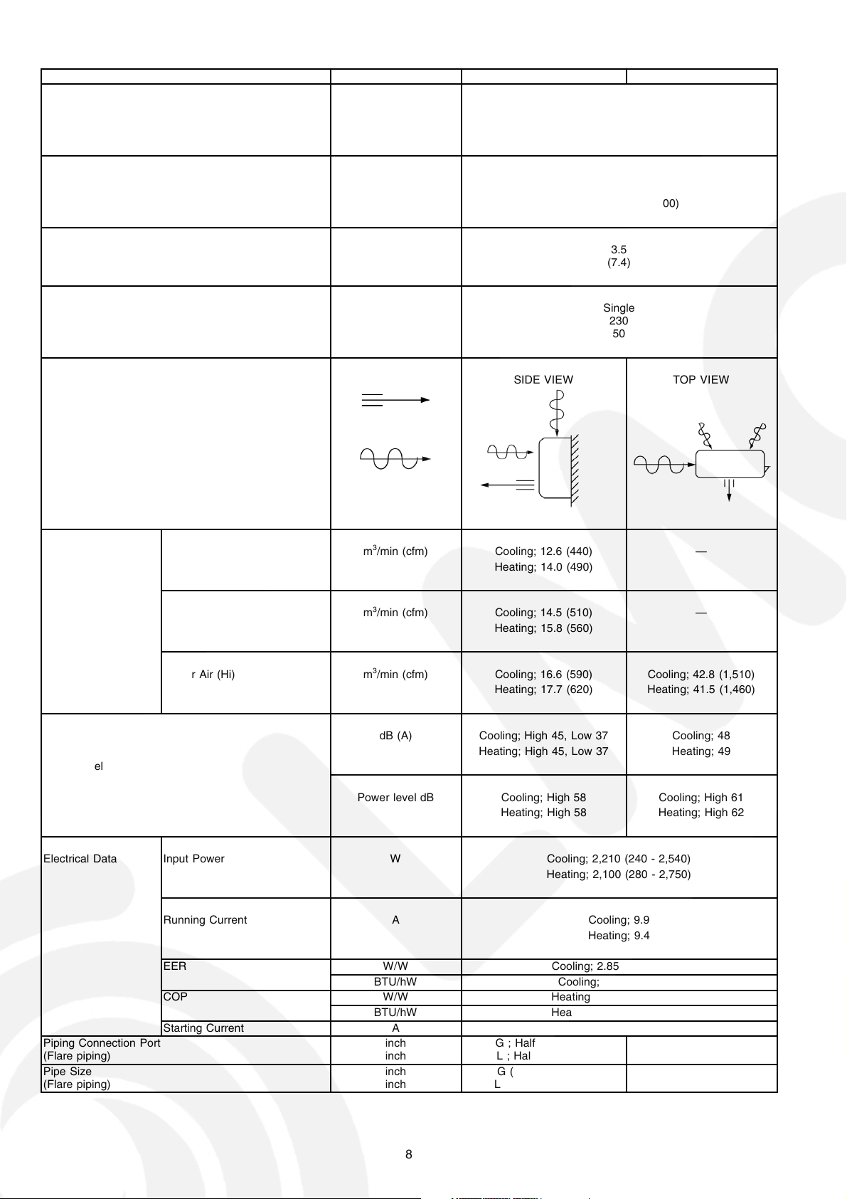
Unit CS-E21CKE CU-E21CKE
Cooling Capacity kW
kcal/h
BTU/h
Heating Capacity kW
kcal/h
BTU/h
Moisture Removal l/h
Pint/h
Power Source Phase
V
Cycle
Airflow Method OUTLET
INTAKE
6.30 (0.90 - 7.10)
5,420 (770 - 6,110)
21,500 (3,070 - 24,200)
7.20 (0.90 - 8.50)
6,190 (770 - 7,310)
24,600 (3,070 - 29,000)
3.5
(7.4)
Single
230
50
SIDE VIEW TOP VIEW
Air Volume Indoor Air (Lo) m3/min (cfm) Cooling; 12.6 (440) —
Heating; 14.0 (490)
Indoor Air (Me) m3/min (cfm) Cooling; 14.5 (510) —
Heating; 15.8 (560)
Indoor Air (Hi) m3/min (cfm) Cooling; 16.6 (590) Cooling; 42.8 (1,510)
Heating; 17.7 (620) Heating; 41.5 (1,460)
dB (A) Cooling; High 45, Low 37 Cooling; 48
Heating; High 45, Low 37 Heating; 49
Noise Level
Power level dB Cooling; High 58 Cooling; High 61
Heating; High 58 Heating; High 62
Electrical Data Input Power W Cooling; 2,210 (240 - 2,540)
Heating; 2,100 (280 - 2,750)
Running Current A Cooling; 9.9
Heating; 9.4
Piping Connection Port
(Flare piping)
Pipe Size
(Flare piping)
EER W/W Cooling; 2.85 (3.75 - 2.80)
BTU/hW Cooling; 9.7 (12.8 - 9.5)
COP W/W Heating; 3.43 (3.21 - 3.09)
BTU/hW Heating; 11.7 (11.0 - 10.5)
Starting Current A 9.4
inch
inch
inch
inch
G ; Half Union 1/2”
L ; Half Union 1/4”
G (gas side) ; 1/2”
L (liquid side) ; 1/4”
G ; 3-way valve 1/2”
L ; 2-way valve 1/4”
G (gas side) ; 1/2”
L (liquid side) ; 1/4”
8
Unit CS-E21CKE CU-E21CKE
Drain
Hose
Power Cord Length
Number of core-wire
Dimensions Height inch (mm) 10 - 13/16 (275) 29 - 17/32 (750)
Net Weight lb (kg) 24 (11) 112 (51)
Compressor Type — Involute scroll
Air Circulation Type Cross-flow Fan Propeller Fan
Heat Exchanger Description Evaporator Condenser
Refrigerant Control Device — Expansion Valve
Refrigeration Oil (c.c) — RB68A (360)
Refrigerant (R410A) kg (oz) — 1.29 (45.5)
Thermostat Electronic Control —
Protection Device Electronic Control Electronic Control
Capillary Tube Flow Rate l/min — —
Air Filter Material
Inner diameter mm 12 —
Length m 0.65 —
3 core wires × 1.5 mm
Width inch (mm) 39 - 9/32 (998) 34 - 7/16 (875)
Depth inch (mm) 8 - 9/32 (210) 13 - 19/32 (345)
Motor Type — Brushless (4-pole)
Rated Output W — 900
Material ASHT-18 P.P
Motor Type Transistor (8-poles) Transistor (8-poles)
Rate Output W 30 40
Fan Speed Lo (Cool/Heat) rpm 1,150 / 1,270 —
Me (Cool/Heat) rpm 1,330 / 1,440 —
Hi (Cool/Heat) rpm 1,520 / 1,610 700 / 680
Tube material Copper Copper
Fin material Aluminium (Pre Coat) Aluminium (Blue Coated)
Fin Type Slit Fin Corrugated Fin
Row / Stage (Plate fin configuration, forced draft)
FPI 21 18
Size (W × H × L) mm 810 × 315 × 25.4 849.3
Length mm — —
Inner Diameter mm — —
Style
2.1 m
2/15 2/34
P.P.
Honeycomb
2
—
—
× 714 × 36.4
878
—
•
Specifications are subjected to change without notice for further improvement.
9
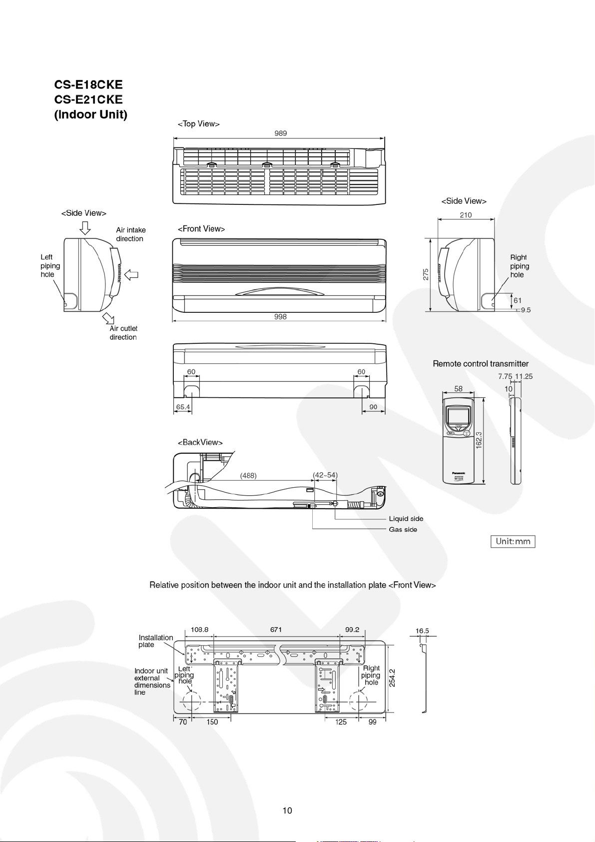
4 Dimensions
10
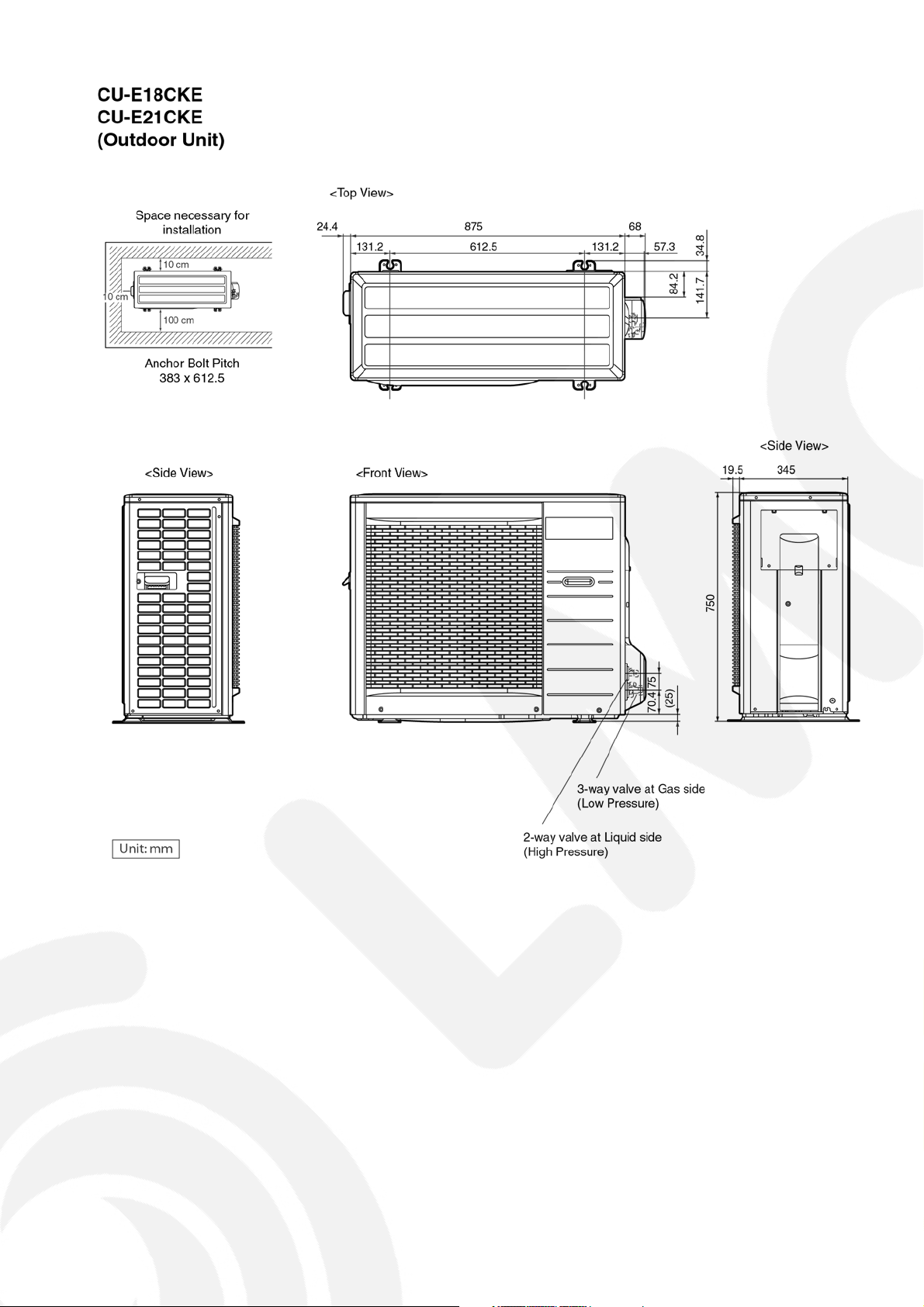
11
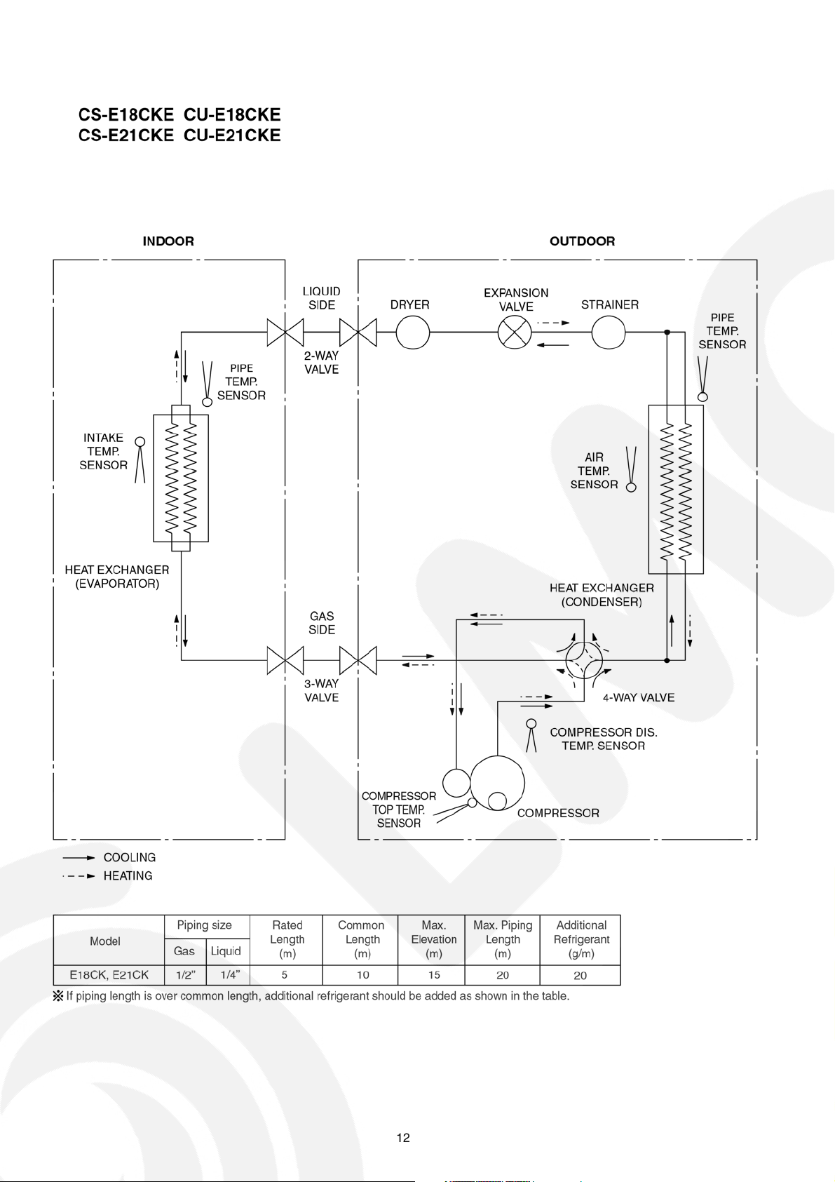
5 Refrigeration Cycle Diagram
12
6 Block Diagram
13
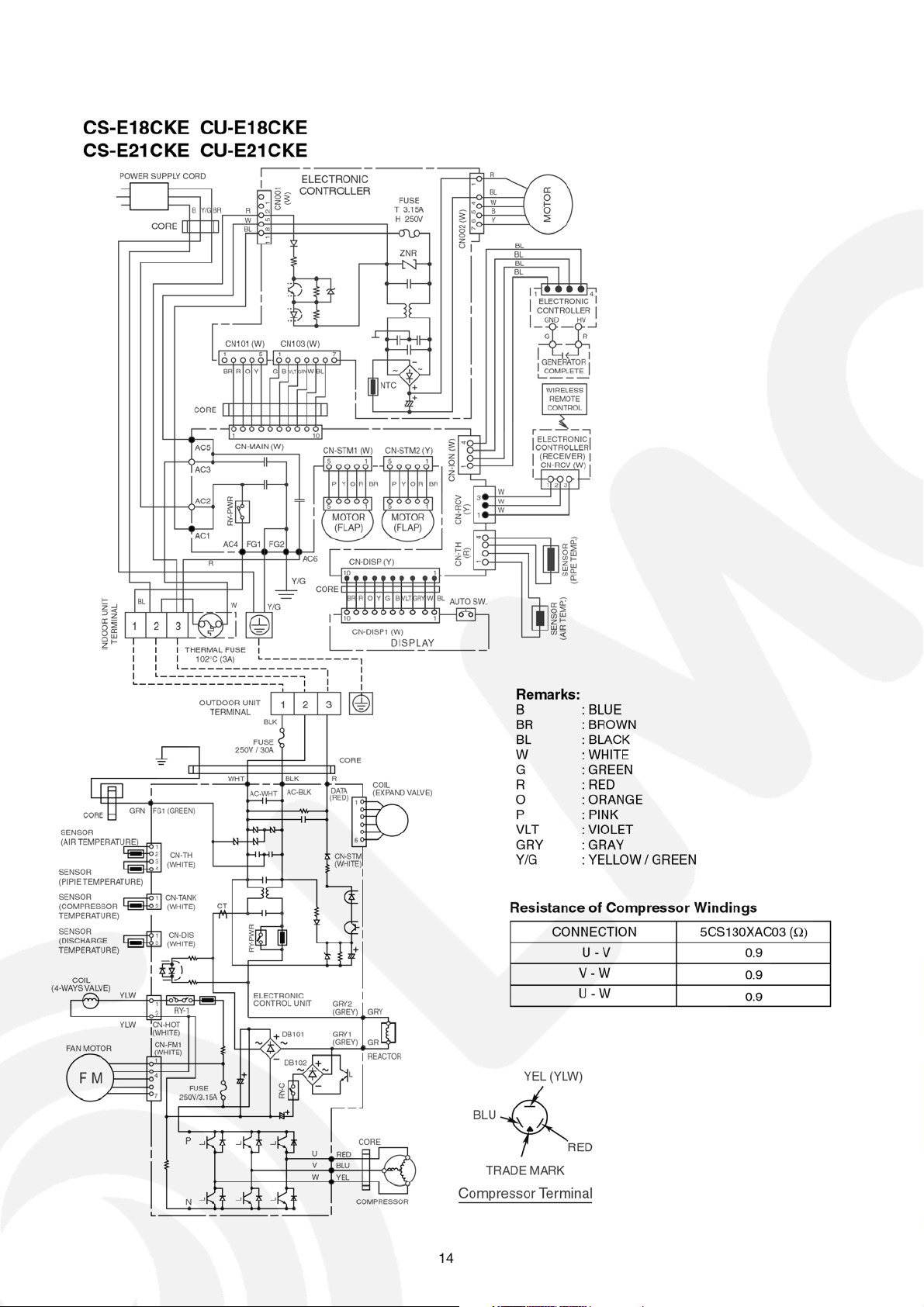
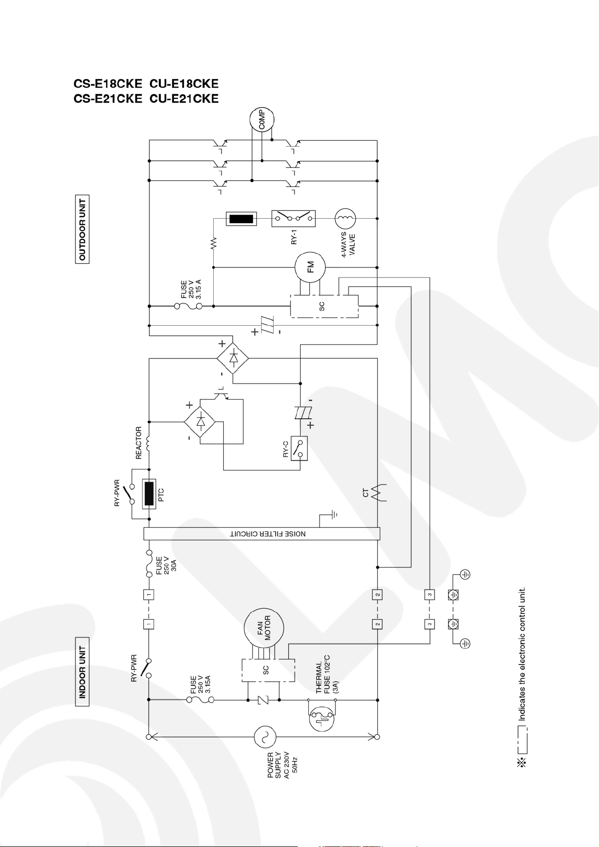
7 Wiring Diagram
14
8 Operation Details
8.1. BASIC FUNCTION
Inverter control, which equipped with a microcomputer in determining the most suitable operating mode as time passes,
automatically adjusts output power for maximum comfort always. In order to achieve the suitable operating mode, the
microcomputer maintains the set temperature by measuring the temperature of the environment and performing temperature
shifting. The compressor at outdoor unit is operating following the frequency instructed by the microcomputer at indoor unit that
judging the condition according to internal setting temperature and intake air temperature.
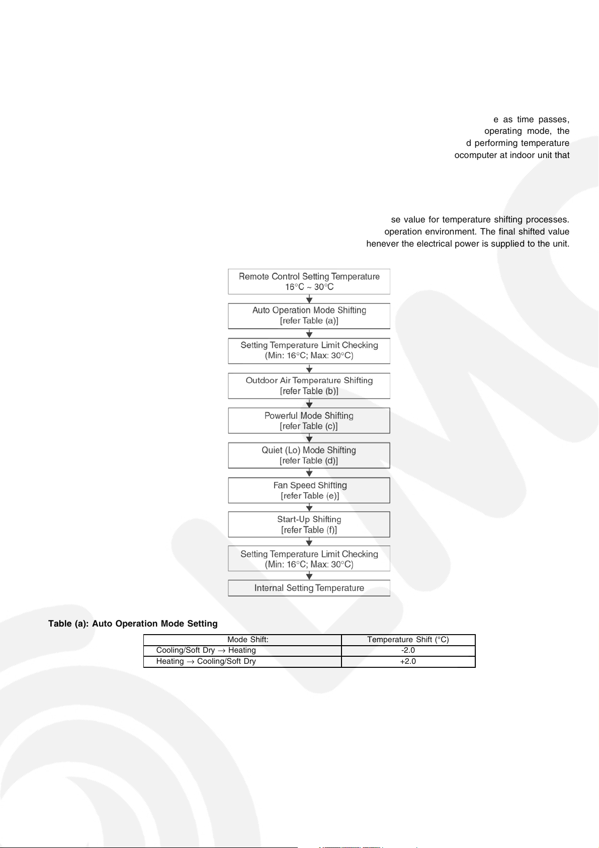
8.1.1. Internal Setting Temperature
Once the operation starts, remote control setting temperature will be taken as base value for temperature shifting processes.
These shifting processes are depend ing on the air conditioner settings and the operation environment. The final shifted value
will be used as internal setting temperature and it is updated continuously whenever the electrical power is supplied to the unit.
Table (a): Auto Operation Mode Setting
Cooling/Soft Dry→Heating -2.0
Heating→Cooling/Soft Dry +2.0
Mode Shift: Temperature Shift (°C)
15
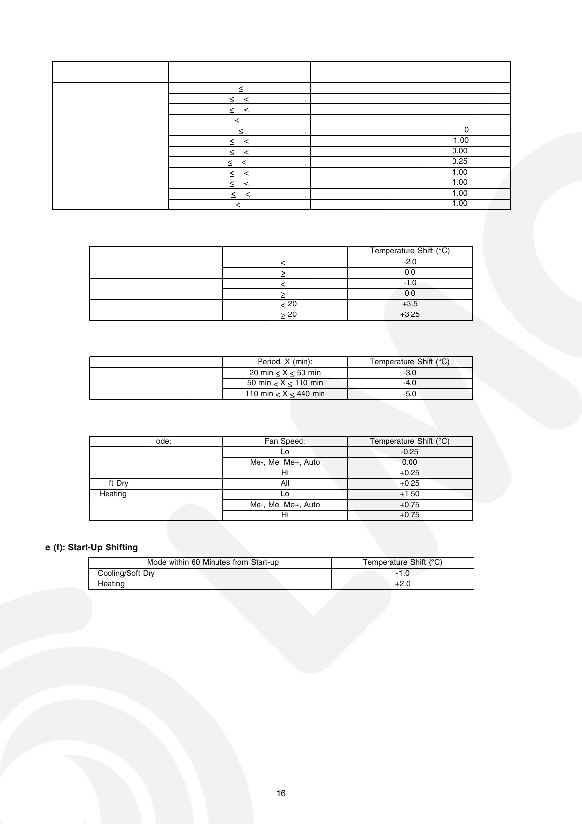
Table (b): Outdoor Air Temperature Shifting
Mode: Outdoor Temperature, X (°C): Temperature Shift (°C)
Cooling/Soft Dry 38 X 1.50 2.00
Heating 21 X -2.25 -1.50
Table (c): Powerful Mode Shifting
Mode: Period, X (min): Temperature Shift (°C)
Cooling X 20 -2.0
Soft Dry X 20 -1.0
Heating X 20 +3.5
Manual Operation Auto Operation
30 X 38 1.25 1.25
23 X 30 1.25 1.25
X 23 1.75 1.75
17 X 21 -1.75 -1.00
13 X 17 -0.75 0.00
9 X 13 0.25 0.25
5 X 9 1.25 1.00
1 X 5 0.75 1.00
-3 X 1 1.50 1.00
X -3 1.50 1.00
X 20 0.0
X 20 0.0
X 20 +3.25
Table (d): Quiet (Lo) Mode Shifting
Mode: Period, X (min): Temperature Shift (°C)
Cooling, Soft Dry 20 min X 50 min -3.0
Table (e): Fan Speed Shifting
Mode: Fan Speed: Temperature Shift (°C)
Cooling Lo -0.25
Soft Dry All +0.25
Heating Lo +1.50
Table (f): Start-Up Shifting
Mode within 60 Minutes from Start-up: Temperature Shift (°C)
Cooling/Soft Dry -1.0
Heating +2.0
50 min X 110 min -4.0
110 min X 440 min -5.0
Me-, Me, Me+, Auto 0.00
Hi +0.25
Me-, Me, Me+, Auto +0.75
Hi +0.75
16
8.1.2. Compressor Operation Frequency
Intake Air Temperature - Internal Setting Temperature (°C) Freq. H
Zone Cooling & Soft Dry Heating Cooling Soft Dry Heating Remark
1 -2.0 1.5 1 1 1
2 -1.5 1.0 1 1 1
3 -1.0 0.5 14 8 11
4 -0.5 0.0 20 8 15
5 0.0 -0.5 27 8 22
6 0.5 -1.0 35 11 27
7 1.0 -1.5 43 11 36
8 1.5 -2.0 46 11 39 Fc, Fh
9 2.0 -2.5 46 11 39 Fc, Fh
10 2.5 -3.0 46 11 39 Fc, Fh
11 Nil -3.5 Nil Nil 39 Fh
12 Nil -4.0 Nil Nil 39 Fh
Operating Frequency Calculation Formula:
CompHz = Freq. A × Freq. H + Freq. C
Example Calculation:
Model No.: E18CK
Operation Mode: Cooling
When Intake Air Temperature - Internal setting Temperature:
1.5°C
CompHz = Freq. A × Freq. H + Freq. C
= 1.53 × 46 + 2.5
= 72 Hz (It cuts down less than a decimal point)
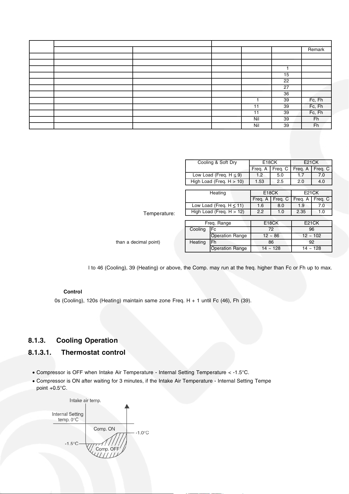
Cooling & Soft Dry E18CK E21CK
Freq. A Freq. C Freq. A Freq. C
Low Load (Freq. H 9) 1.2 5.0 1.7 7.0
High Load (Freq. H > 10) 1.53 2.5 2.0 4.0
Heating E18CK E21CK
Freq. A Freq. C Freq. A Freq. C
Low Load (Freq. H 11) 1.6 8.0 1.9 7.0
High Load (Freq. H > 12) 2.2 1.0 2.35 1.0
Freq. Range E18CK E21CK
Cooling Fc 72 96
Operation Range 12 ~ 86 12 ~ 102
Heating Fh 86 92
Operation Range 14 ~ 128 14 ~ 128
Remarks:
When Freq. H is equal to 46 (Cooling), 39 (Heating) or above, the Comp. may run at the freq. higher than Fc or Fh up to max.
freq. operation.
Best Amenity Control
Every 90s (Cooling), 120s (Heating) maintain same zone Freq. H + 1 until Fc (46), Fh (39).
8.1.3. Cooling Operation
8.1.3.1. Thermostat control
• Compressor is OFF when Intake Air Temperature - Internal Setting Temperature < -1.5°C.
• Compressor is ON after waiting for 3 minutes, if the Intake Air Temperature - Internal Setting Temperature > Compressor OFF
point +0.5°C.
17
8.1.4. Soft Dry Operation
8.1.4.1. Thermostat control
• Compressor is OFF when Intake Air Temperature - Internal Setting Temperature < -2.5°C.
• Compressor is ON after waiting for 3 minutes, if the Intake Air Temperature - Internal Setting Temperature > Compressor OFF
point.
8.1.5. Heating Operation
8.1.5.1. Thermostat control
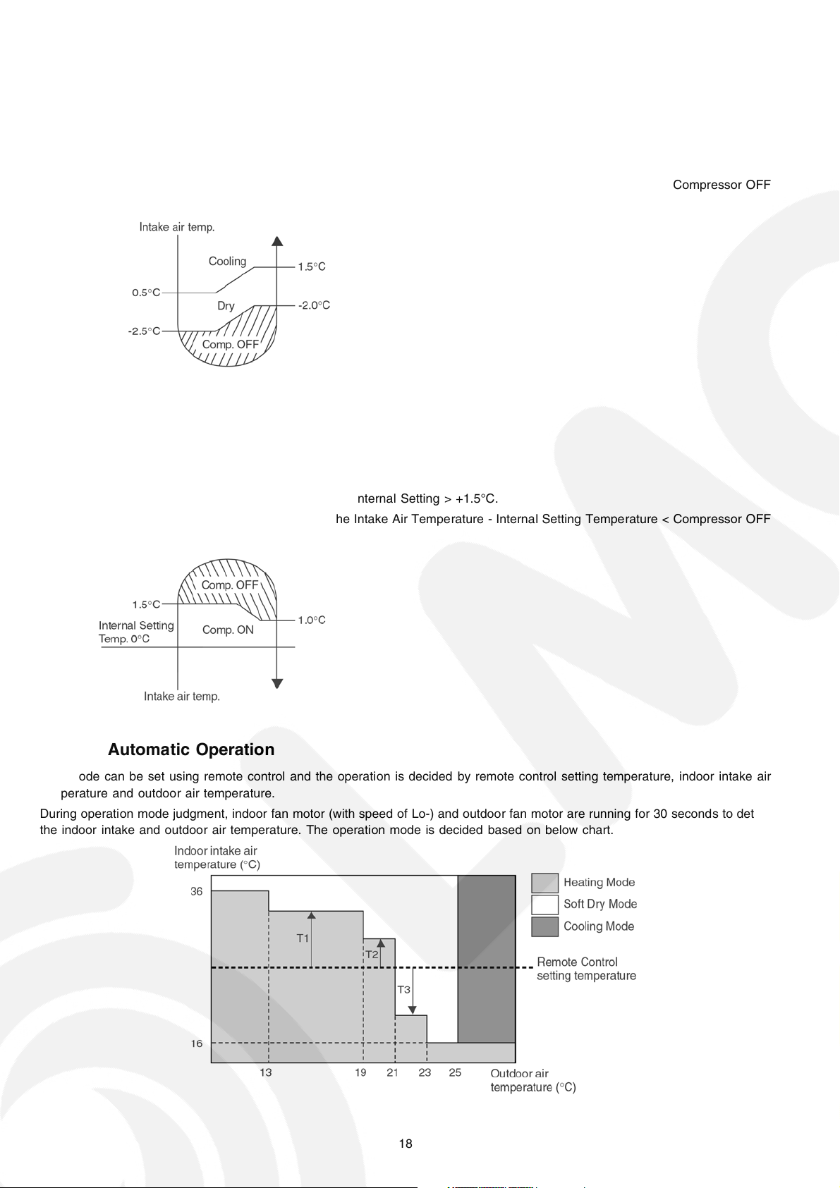
• Compressor is OFF when Intake Air Temperature - Internal Setting > +1.5°C.
• Compressor is ON after waiting for 3 minutes, if the Intake Air Temperature - Internal Setting Temperature < Compressor OFF
point -0.5°C.
8.1.6. Automatic Operation
This mode can be set using remote control and the operation is decided by remote control setting temperature, indoor intake air
temperature and outdoor air temperature.
During operation mode judgment, indoor fan motor (with speed of Lo-) and outdoor fan motor are running for 30 seconds to detect
the indoor intake and outdoor air temperature. The operation mode is decided based on below chart.
18
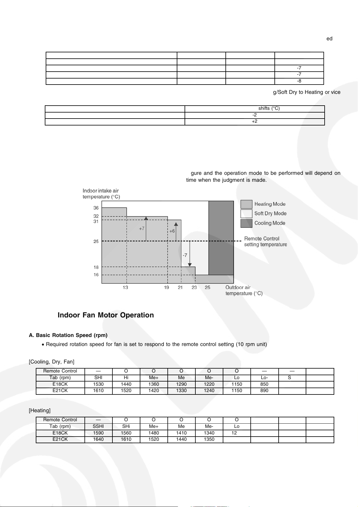
Values of T1, T2, and T3 depend on remote control setting temperature, as shown in below table. After the adjustment of T1, T2
and T3 values, the operation mode for that particular environment and remote control setting is judged and performed, based on
the above operation mode chart, every 30 minutes.
Remote Control Setting Temperature (°C) T1 T2 T3
16 ~ 18 +10 +8 -5
19 ~ 22 +8 +7 -7
23 ~ 26 +7 +6 -7
27 ~ 30 +6 +5 -8
There is a temperature shifting on T1, T2, and T3 if the operation mode judged is changed from Cooling/Soft Dry to Heating or vice
verse.
Operation Mode change from Temperature shifts (°C)
Cooling/Soft Dry→Heating -2
Heating→Cooling/Soft Dry +2
Example of operation mode chart adjustment:
From the above table, if remote control setting temperature = 25,
T1 = 25 + 7 = 32; T2 = 25 + 6 = 31; T3 = 25 - 7 = 18
The operation mode chart for this example is as shown in below figure and the operation mode to be performed will depend on
indoor intake air temperature and outdoor air temperature at the time when the judgment is made.
8.1.7. Indoor Fan Motor Operation
A. Basic Rotation Speed (rpm)
Required rotation speed for fan is set to respond to the remote control setting (10 rpm unit)
•
[Cooling, Dry, Fan]
Remote Control — O O O O O — — —
Tab (rpm) SHI Hi Me+ Me Me- Lo Lo- SLo SSLo
E18CK 1530 1440 1360 1290 1220 1150 850 760 630
E21CK 1610 1520 1420 1330 1240 1150 890 800 630
[Heating]
Remote Control — O O O O O — — —
Tab (rpm) SSHI SHi Me+ Me Me- Lo Lo- SLo SSLo
E18CK 1590 1560 1480 1410 1340 1270 850 400 300
E21CK 1640 1610 1520 1440 1350 1270 890 400 300
19
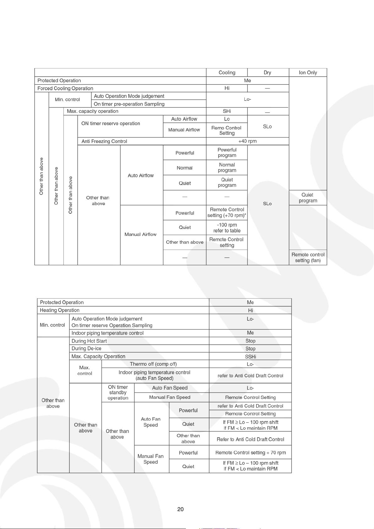
B. Indoor Fan Control
i. Indoor fan control operation outline
1. Cooling / Dry
2. Heating
20
ii. Auto Fan Speed
1. Cooling
2. Heating
Note:
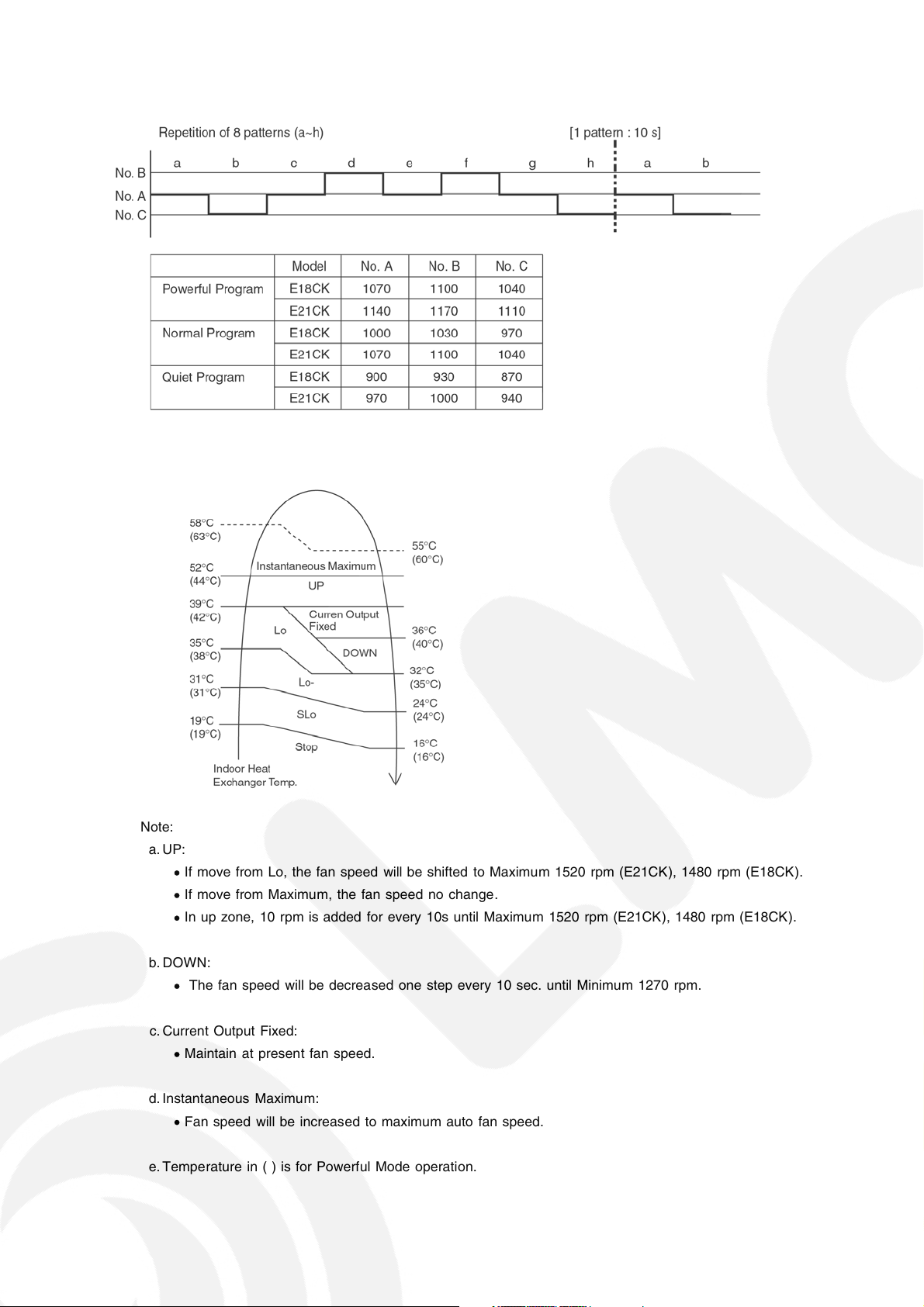
a. UP:
• If move from Lo, the fan speed will be shifted to Maximum 1520 rpm (E21CK), 1480 rpm (E18CK).
• If move from Maximum, the fan speed no change.
• In up zone, 10 rpm is added for every 10s until Maximum 1520 rpm (E21CK), 1480 rpm (E18CK).
b. DOWN:
• The fan speed will be decreased one step every 10 sec. until Minimum 1270 rpm.
c. Current Output Fixed:
• Maintain at present fan speed.
d. Instantaneous Maximum:
• Fan speed will be increased to maximum auto fan speed.
e. Temperature in ( ) is for Powerful Mode operation.
21
iii. Max Capacity Condition
a) During Cooling operation, if all to the followin g condition is fulfilled , the indoor fan speed is set to Shi.
1. Indoor intake temperature
24°C.
2. Operation frequency 72 Hz (E18CK), 95 Hz (E21CK) & above.
3. Remote Control setting temperature 16°C.
4. Remote Control setting fan speed Hi.
5. Outdoor temperature
6. Operation start
30°C.
within 30 minutes.
* If any of above conditions is not valid, the condition is ended.
b) During Heating operation, if all to the followin g condition is fulfilled , the indoor fan speed is set to SSHi.
1. Indoor intake temperature is 17°C or above and less than 23°C.
2. Operation frequency 86 Hz (E18CK), 93 Hz (E21CK) & above.
3. Remote Control setting temperature 30°C.
4. Remote Control setting fan speed Hi.
5. Outdoor temperature < 4°C.
6. Operation start
2 hours.
* If any of above conditions is not valid, the condition is ended.
C. Fan Motor Control
i. Motor specification
High voltage PWM Motor
ii. Feedba ck Control
1. Rotation speed feedback
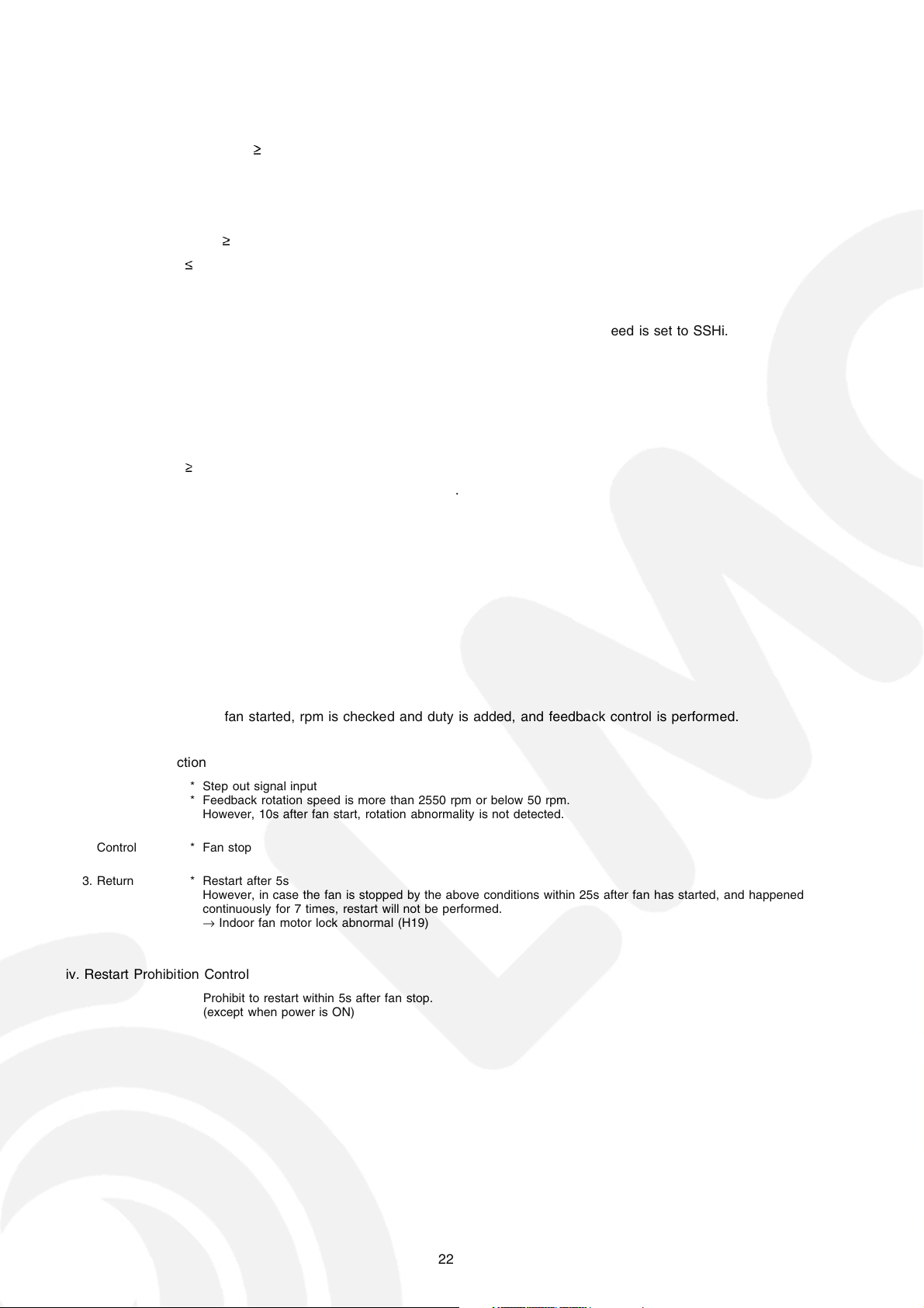
Immediately after the fan started, rpm is checked and duty is added, and feedback control is performed.
iii. Abnormal Detection
1. Condition **Step out signal input
2. Control * Fan stop
3. Return * Restart after 5s
Feedback rotation speed is more than 2550 rpm or below 50 rpm.
However, 10s after fan start, rotation abnormality is not detected.
However, in case the fan is stopped by the above conditions within 25s after fan has started, and happened
continuously for 7 times, restart will not be performed.
Indoor fan motor lock abnormal (H19)
→
iv. Restart Prohibition Control
Prohibit to restart within 5s after fan stop.
(except when power is ON)
22
D. Deodorizing Control
i. Control condition
Control at cooling/dry operation and auto fan speed.
No Deodorizing Control is performed during ON timer standby operation and during Anti-freezing control prevention.
ii. Operation
The odor status is arranged as below and it is shifted as follow.
* When COMP is ON 1→2→3
(Shift to 4 when COMP is OFF)
* When COMP is OFF 4→5→4
(Shift to 1 when COMP is ON)
* Start from 4 if the Thermostat is OFF during the start operation.
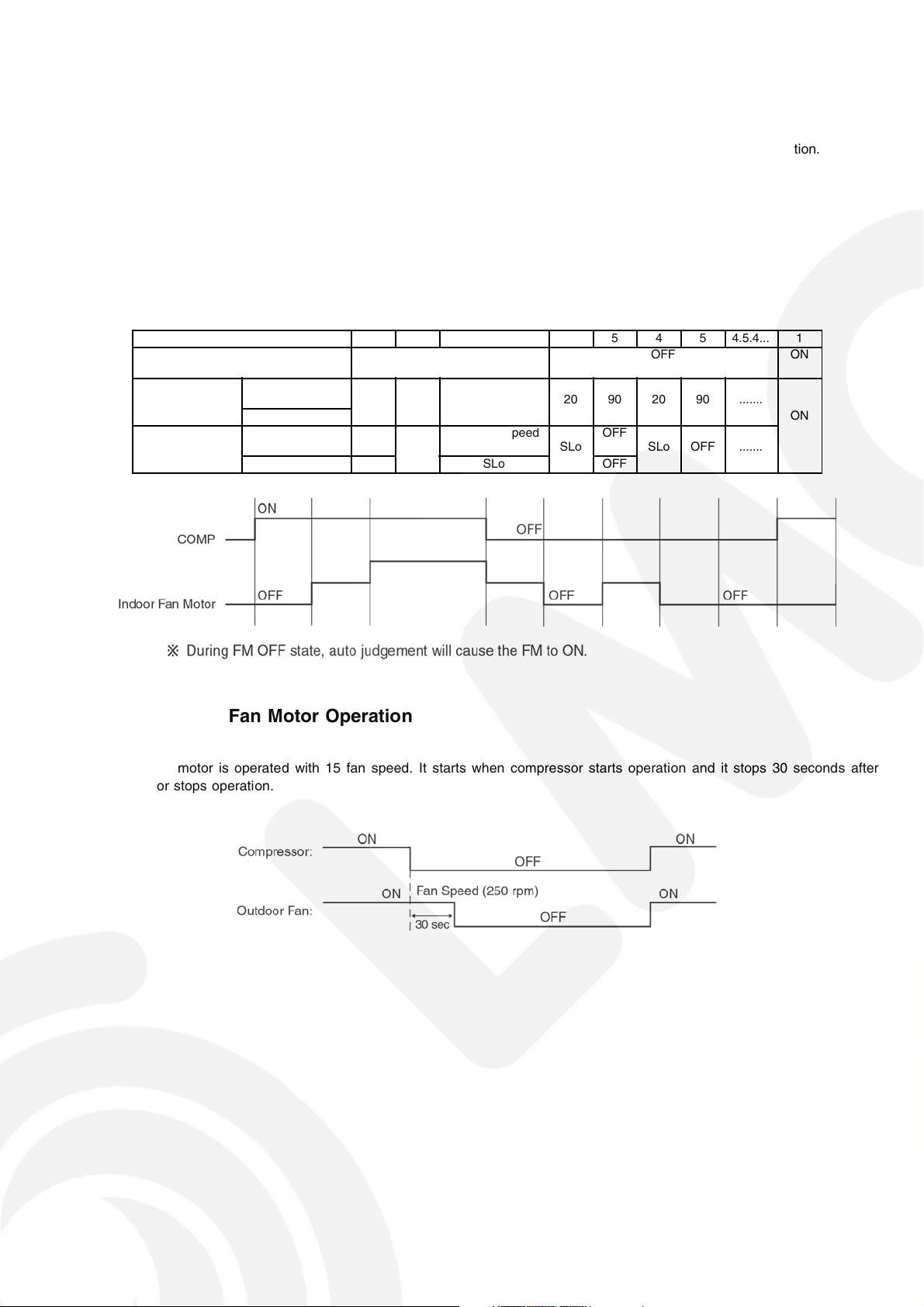
Odor Status 1 2 3 4 5 4 5 4.5.4... 1
Status Shift
according to COMP
Status Shift
according
to time (s) Dry zone ON
Fan Speed
Cooling
zone
Cooling
zone
Dry zone OFF SLo OFF
40 50 — 20 90 20 90 .......
OFF
ON OFF ON
Auto Fan Speed
SLo
SLo
←→
5
OFF
SLo OFF .......
8.1.8. Outdoor Fan Motor Operation
Outdoor fan motor is operated with 15 fan speed. It starts when compressor starts operation and it stops 30 seconds after
compressor stops operation.
23
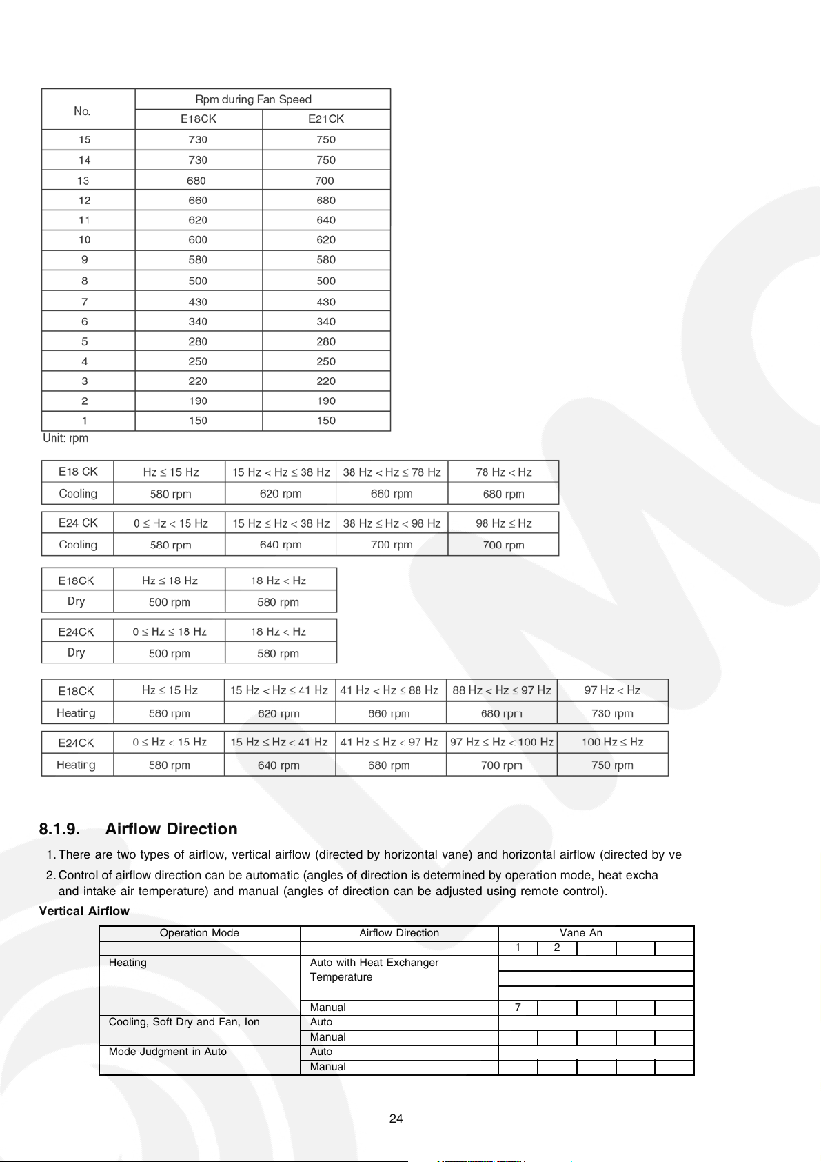
Basic Rotation Speed
8.1.9. Airflow Direction
1. There are two types of airflow, vertical airflow (directed by horizontal vane) and horizontal airflow (directed by vertical vanes).
2. Control of airflow direction can be automatic (angles of direction is determined by operation mode, heat exchanger temperature
and intake air temperature) and manual (angles of direction can be adjusted using remote control).
Vertical Airflow
Operation Mode Airflow Direction Vane Angle (°)
1 2 3 4 5
Heating Auto with Heat Exchanger 17
Temperature 58
7
Manual 7 17 33 49 67
Cooling, Soft Dry and Fan, Ion Auto 7~37
Manual 7 17 25 33 41
Mode Judgment in Auto Auto 7
Manual 7 17 25 33 41
24
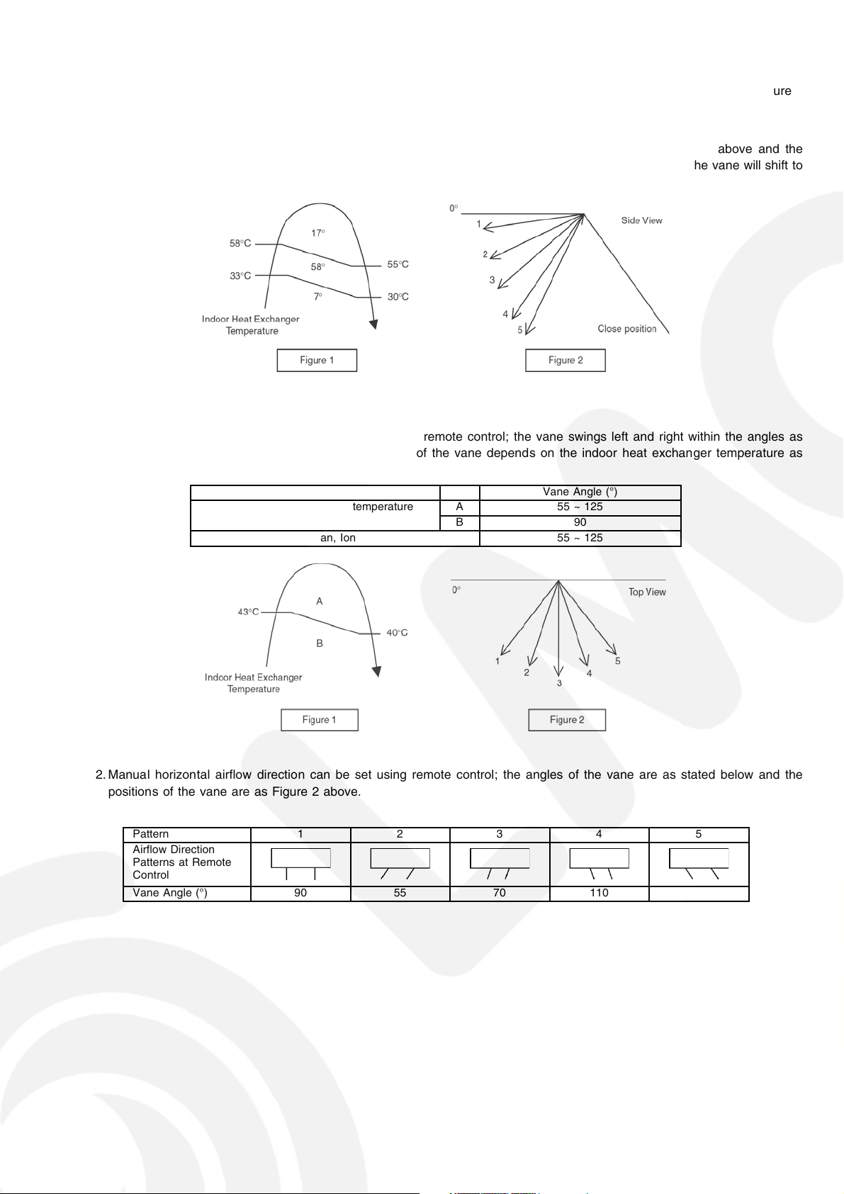
1. Automatic vertical airflow direction can be set using remote control; the vane swings up and down within the angles as stated
above. For heating mode operation, the angle of the vane depends on the indoor heat exchanger temperature as Figure 1
below. When the air conditioner is stopped using remote control, the vane will shift to close position.
2. Manual vertical airflow direction can be set using remote control; the angles of the vane are as stated above and the
positions of the vane are as Figure 2 below. When the air conditioner is stopped using remote control, the vane will shift to
close position.
Horizontal Airflow
1. Automatic horizontal airflow direction can be set using remote control; the vane swings left and right within the angles as
stated below. For heating mode operation, the angle of the vane depends on the indoor heat exchan ger temperature as
Figure 1 below.
Operation Mode Vane Angle (°)
Heating, with heat exchanger temperature A 55 ~ 125
B 90
Cooling, Soft Dry and Fan, Ion 55 ~ 125
2. Manual horizontal airflow direction can be set using remote control; the angles of the vane are as stated below and the
positions of the vane are as Figure 2 above.
Pattern 1 2 3 4 5
Airflow Direction
Patterns at Remote
Control
Vane Angle (°) 90 55 70 110 125
25
8.1.10. Quiet operation (Cooling Mode/Cooling area of Dry Mode)
A. Purpose
To provide quiet cooling operation compare to normal operation.
B. Control condition
a. Quiet operation start condition
• When “quiet” button at remote control is pressed.
Quiet LED illuminates.
b. Quiet operation stop condition
1. When one of the following conditio ns is satisfied, quiet operation stops:
a. Powerful button is pressed.
b. Stop by OFF/ON switch.
c. Timer “off” activates.
d. When change mode to fan only mode.
e. Quiet button is pressed again.
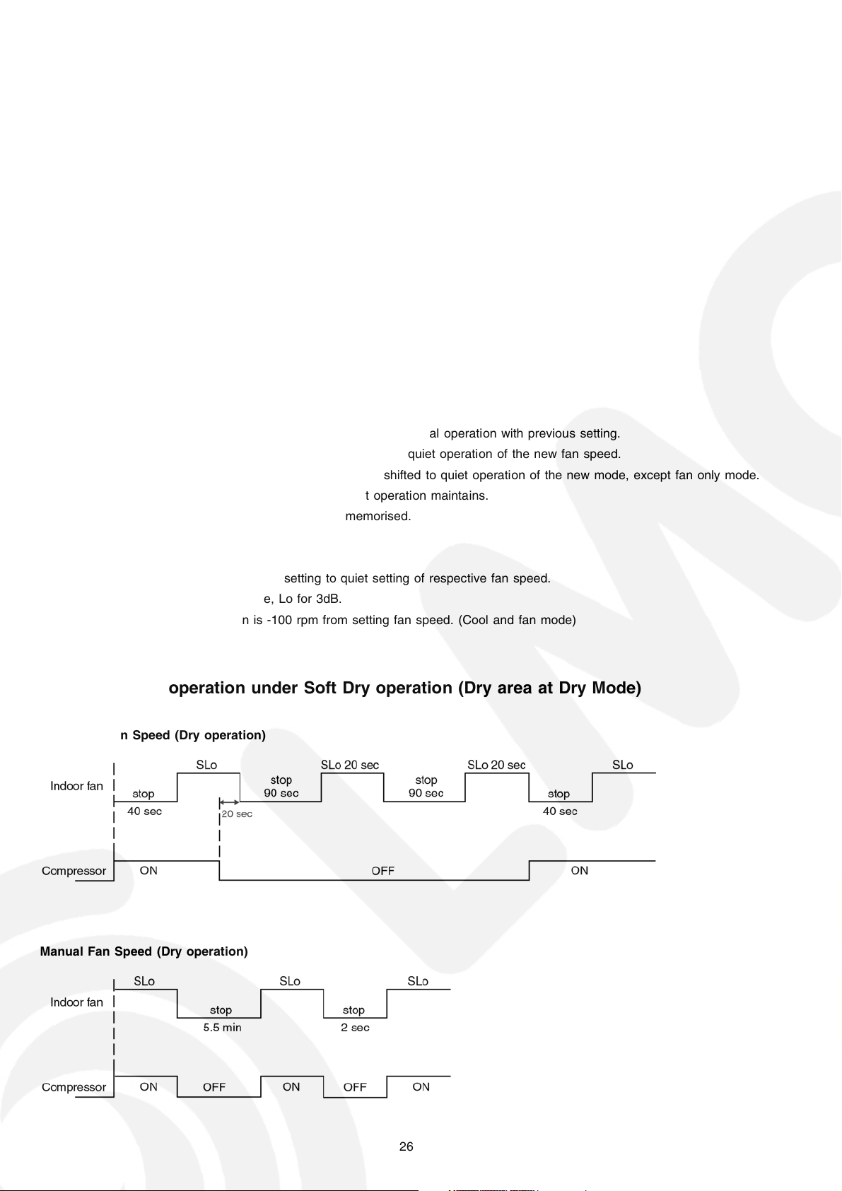
2. When quiet operation is stopped, operation is shifted to normal operation with previous setting.
3. When fan speed is changed, quiet operation is shifted to quiet operation of the new fan speed.
4. When operation mode is changed, quiet operation is shifted to quiet operation of the new mode, except fan only mode.
5. During quiet operation, if timer “on” activates, quiet operation maintains.
6. After off, when on back, quiet operation is not memorised.
D. Control contents
1. Fan speed is changed from normal setting to quiet setting of respective fan speed.
This is to reduce sound of Hi, Me, Lo for 3dB.
2. Fan speed for quiet operation is -100 rpm from setting fan speed. (Cool and fan mode)
8.1.10.1. Quiet operation under Soft Dry operation (Dry area at Dry Mode)
Automatic Fan Speed (Dry operation)
Manual Fan Speed (Dry operation)
26
8.1.10.2. Quiet operation (Heating)
A. Purpose
To provide quiet heating operation compare to normal operation.
B. Control condition
a. Quiet operation start condition
• When “quiet” button at remote control is pressed.
Quiet LED illuminates.
b. Quiet operation stop condition
1. When one of the following conditio ns is satisfied, quiet operation stops:
a. Powerful button is pressed.
b. Stop by OFF/ON switch.
c. Timer “off” activates.
d. When change mode to fan only mode.
e. Quiet button is pressed again.
2. When quiet operation is stopped, operation is shifted to normal operation with previous setting.
3. When fan speed is changed, quiet operation is shifted to quiet operation of the new fan speed.
4. When operation mode is changed, quiet operation is shifted to quiet operation of the new mode, except fan only mode.
5. During quiet operation, if timer “on” activates, quiet operation maintains.
6. After off, when on back, quiet operation is not memorised.
C. Control contents
a. Fan Speed manual
1. Fan speed is changed from normal setting to quiet setting of respective fan speed.
This is to reduce sound of Hi, Me, Lo for 3dB.
2. Fan speed for quiet operation is -100 rpm from setting fan speed.
3. Fan Speed Auto
• If FM
-100 rpm reduce from normal Heating Auto Fan Speed
• If FM
maintain RPM
Indoor FM RPM depends on pipe temp sensor of indoor heat exchanger.
Lo
Lo
27
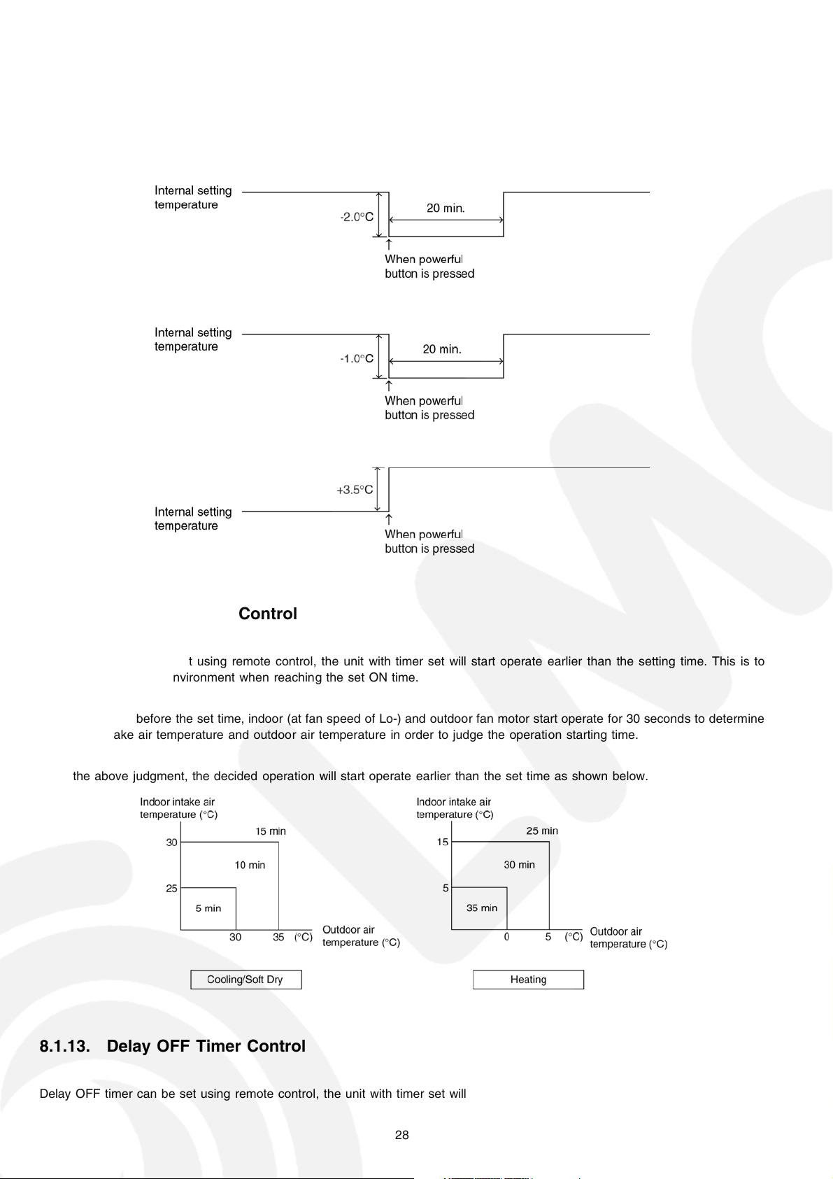
8.1.11. Powerful Mode Operation
When the powerful mode is selected, the internal setting temperature will shift to achieve the setting temperature quickly.
(a) Cooling Operation
(b) Soft Dry Operation
(c) Heating Operation
8.1.12. Delay ON Timer Control
Delay ON timer can be set using remote control, the unit with timer set will start operate earlier than the setting time. This is to
provide a comfortable environment when reaching the set ON time.
Seventy minutes before the set time, indoor (at fan speed of Lo-) and outdoor fan motor start operate for 30 seconds to determine
the indoor intake air temperature and outdoor air temperature in order to judge the operation starting time.
From the above judgment, the decided operation will start operate earlier than the set time as shown below.
8.1.13. Delay OFF Timer Control
Delay OFF timer can be set using remote control, the unit with timer set will stop operate at set time.
28
8.1.14. Auto Restart Control
1. When the power supply is cut off during the operation of air conditioner, the compressor will re-operate within three to four
minutes (there are 10 patterns between 2 minutes 58 seconds and 3 minutes 52 seconds to be selected randomly) after power
supply resumes.
2. This type of control is not applicable during ON/OFF Timer setting.
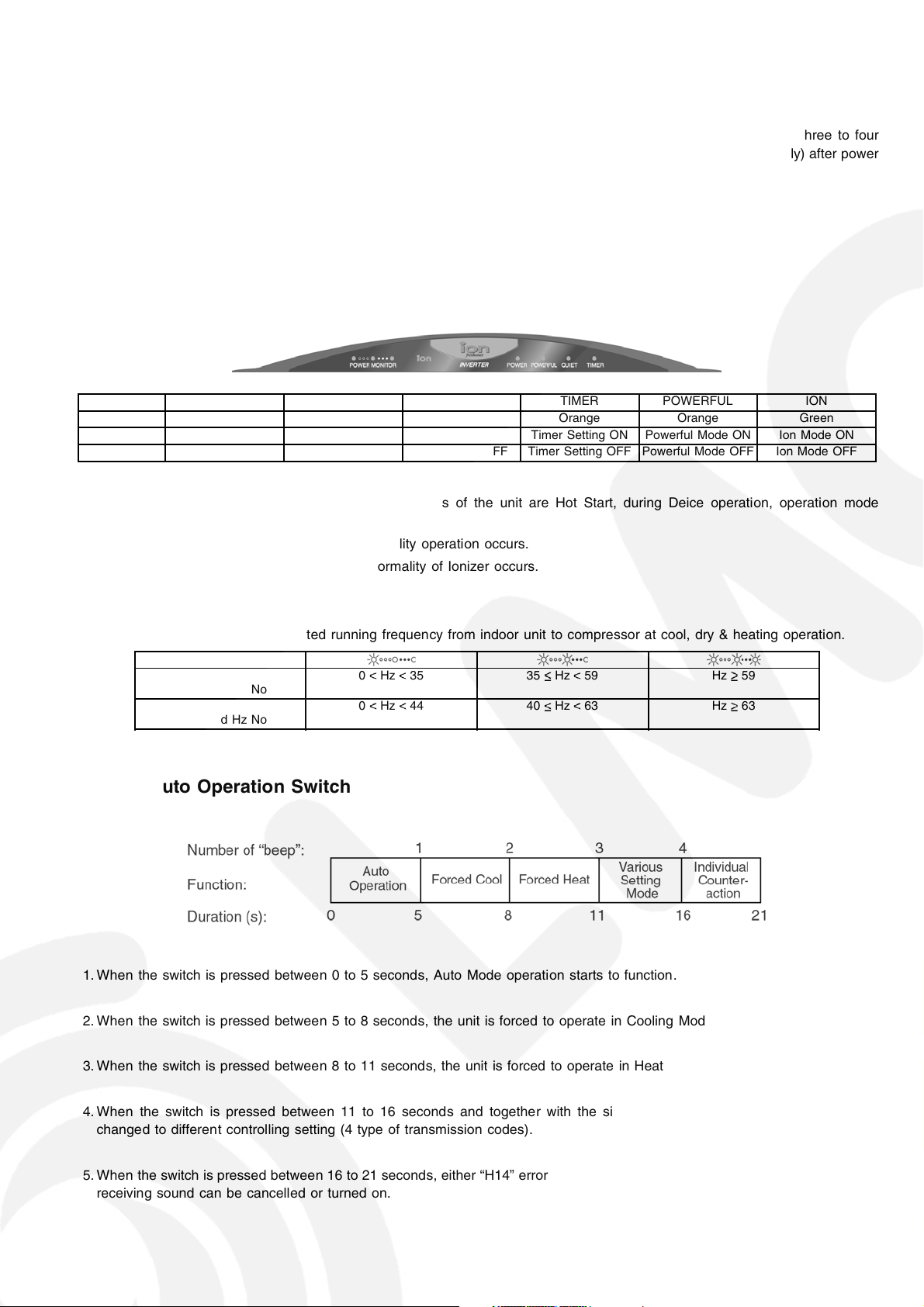
8.1.15. Indication Panel
LED POWER MONITOR POWER QUIET TIMER POWERFUL ION
Color Green Green Orange Orange Orange Green
Light ON Compressor ON Operation ON Quiet Mode ON Timer Setting ON Powerful Mode ON Ion Mode ON
Light OFF Compressor OFF Operation OFF Quiet Mode OFF Timer Setting OFF Powerful Mode OFF Ion Mode OFF
Note:
• If POWER LED is blinking, the possible operations of the unit are Hot Start, during Deice operation, operation mode
judgment, or delay ON timer sampling.
• If Timer LED is blinking, there is an abnormality operation occurs.
• If Ionizer, LED is blinking, there is an abnormality of Ionizer occurs.
Power Monitor LED Control Frequency
Lighting of 3 LED base on instructed running frequency from indoor unit to compressor at cool, dry & heating operation.
Position of LED
Cool, Dry
Instructed Hz No
Heat
Instructed Hz No
0 Hz 35 35 Hz 59 Hz 59
0 Hz 44 40 Hz 63 Hz 63
8.1.16. Auto Operation Switch
1. When the switch is pressed between 0 to 5 seconds, Auto Mode operation starts to function.
2. When the switch is pressed between 5 to 8 seconds, the unit is forced to operate in Cooling Mode.
3. When the switch is pressed between 8 to 11 seconds, the unit is forced to operate in Heating Mode.
4. When the switch is pressed between 11 to 16 seconds and together with the signal from remote control, the unit can be
changed to different controlling setting (4 type of transmission codes).
5. When the switch is pressed between 16 to 21 seconds, either “H14” error detection selection mode or the remote control signal
receiving sound can be cancelled or turned on.
29
8.1.17. Indoor Power Relay Control
Power relay will turn on during operation or in progress of stopping operation. Although operation stops, the power relay continues
on for three minutes.
However, during instantaneous power failure (< 0.5s), power relay will turn off. Then, it will turn on 2 minutes after power recover
and the unit will operate as previous operation condition.
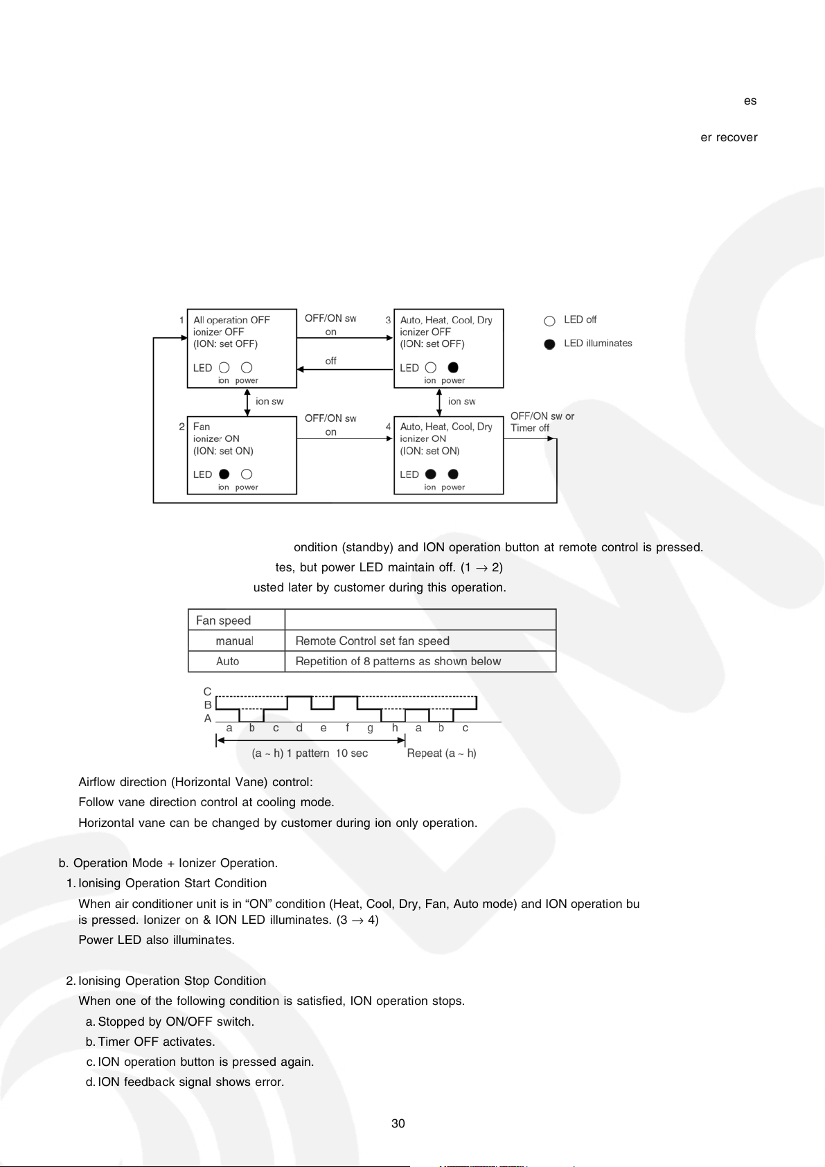
8.1.18. Ionizer Operation
Purpose
To provide fresh air effect to users by discharging minus ion to air.
Control Condition
a. Ionizer Only Operation.
1. When air-conditioner unit is at “OFF” condition (standby) and ION operation button at remote control is pressed.
Fan & ionizer on, ION LED illuminates, but power LED maintain off. (1 → 2)
However, fan speed can be adjusted later by customer during this operation.
Airflow direction (Horizontal Vane) control:
Follow vane direction control at cooling mode.
Horizontal vane can be changed by customer during ion only operation.
b. Operation Mode + Ionizer Operation.
1. Ionising Operation Start Condition
When air conditioner unit is in “ON” condition (Heat, Cool, Dry, Fan, Auto mode) and ION operation button at remote control
is pressed. Ionizer on & ION LED illuminates. (3 → 4)
Power LED also illuminates.
2. Ionising Operation Stop Condition
When one of the following condition is satisfied, ION operation stops.
a. Stopped by ON/OFF switch.
b. Timer OFF activates.
c. ION operation button is pressed again.
d. ION feedback signal shows error.
30
 Loading...