

Panasonic SA-MAX750LMK, BRS11C, SB-MAX750, SA-MAX750, SB-MAX750P Service Manual
© Panasonic Corporation 2013. All rights reserved.
Unauthorized copying and distribution is a violation
of law.
MEX1310012CE
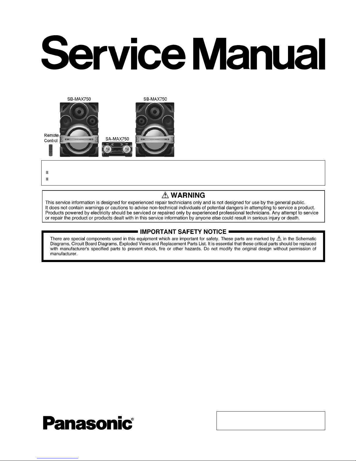
CD Stereo System
Model No. SA-MAX750LMK
Product Color: (K)...Black Type
TABLE OF CONTENTS
1 Safety Precautions
1.1. General Guidelines
1.2. Before Repair and Adjustment
1.3. Protection Circuitry
1.4. Caution For Fuse Replacement
1.5. Safety Parts Information
2 Warning
2.1. Prevention of Electrostatic Discharge (ESD)
to Electrostatically Sensitive (ES) Devices
2.2. Precaution of Laser Diode
2.3. Service caution based on Legal restrictions
2.4. Handling Precautions for Traverse Ass’y
2.5. Grounding for electrostatic breakdown
prevention
3 Service Navigation
3.1. Service Information
3.2. Firmware Update Procedure
4 Specifications
5 General/Introduction
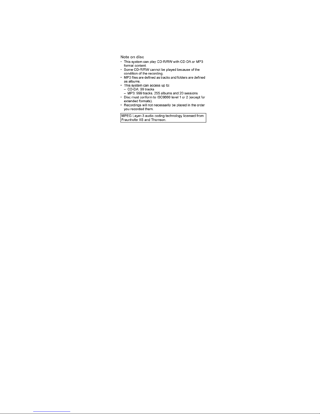
5.1. Media Information
6 Location of Controls and Components
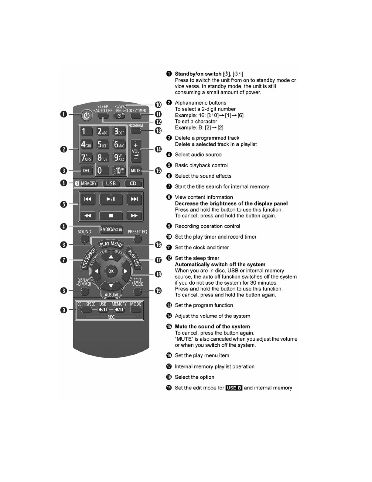
6.1. Remote Control Key Button Operation
6.2. Main Unit Key Button Operation
7 Service Mode
7.1. Cold-Start
7.2. Doctor Mode Table
7.3. Reliability Test Mo
de (CD Mechanism Unit)
7.4. Self-Diagnostic Mode
7.5. Self-Diagnostic Error Code Table
7.6. Sales Demonstration Lock Function
8 Troubleshooting Guide
9 Disassembly and Assembly Instructions
Please refer to the original service manual for:
CD Mechanism Unit, Mechanism (BRS11C) Order No. PSG1201019AE
Speaker system SB-MAX750PHK, Order No. MEX1310013AE
Nota: El idioma original de este Manual de Servicio es en idioma inglés, sin embargo algunas notas
aquí mencionadas serán escritas en español para mejor descripción para Centros de Servicio de México.

9.1. Screw Types
9.2. Disassembly Flow Chart
9.3. Main Components and P.C.B. Locations
9.4. Disassembly of Top Cabinet
9.5. Disassembly of Front Panel Unit
9.6. Disassembly of FL Display P.C.B.
9.7. Disassembly of Bluetooth P.C.B.
9.8. Disassembly of Illumination Button P.C.B.
9.9. Disassembly of Control P.C.B.
9.10. Disassembly of Control Jog LED P.C.B.
9.11. Disassembly of Volume P.C.B.
9.12. Disassembly of Volume Jog LED P.C.B.
9.13. Disassembly of Remote Sensor P.C.B.
9.14. Disassembly of USB P.C.B.
9.15. Disassembly of Mic P.C.B.
9.16. Disassembly of LED P.C.B.
9.17. Disassembly of CD Lid
9.18. Disassembly of Rear Panel
9.19. Disassembly of CD Mechanism Unit
9.20. Disassembly of Main P.C.B.
9.21. Disassembly of SMPS P.C.B.
9.22. Disassembly of Tuner P.C.B.
9.23. Disassembly of CD Interface P.C.B.
1
0 Service Position
10.1. Checking of FL Display P.C.B., Control P.C.B.,
Volume P.C.B., Mic P.C.B. and USB P.C.B.
10.2. Checking of Main P.C.B. (Side B)
10.3. Checking of Main P.C.B. (Side A)
10.4. Checking of SMPS P.C.B.
11 Block Diagram
11.1. Servo & System Control
11.2. Audio
11.3. Power Supply
12 Wiring Connection Diagram
13 Schematic Diagram
13.1. Schematic Diagram Notes -
13.2. Main (CD Servo/Micon/Damp) Circuit
13.3. Bluetooth Circuit
13.4. Tuner Circuit
13.5. FL Display Circuit
13.6. Volume Circuit
13.7. Control & USB Circuit
13.8. Mic Circuit
13.9. Remote Sensor, LED & Illumination Button
Circuit
13.10. SMPS Circuit
13.11. Control Jog LED, Volume Jog LED & CD
Interface Circuit
14 Printed Circuit Board
14.1. Main P.C.B.
14.2. Bluetooth & Tuner P.C.B.
14.3. FL Display & Volume P.C.B.
14.4. Control,
Mic, USB, Remote Sensor, LED &
Illumination Button P.C.B.
14.5. SMPS P.C.B.
14.6. Control Jog LED, Volume Jog LED & CD
Interface P.C.B.
15 Appendix Information of Schematic Diagram
15.1. Voltage & Waveform Chart
16 Exploded View and Replacement Parts List
16.1. Exploded View and Mechanical Replacement
Part List
16.2. Electrical Replacement Part List
1 Safety Precautions
1.1. General Guidelines
1. IMPORTANT SAFETY NOTICE
There are special components used in this equipment which are important for safety. These parts are marked by in the
Schematic Diagrams, Circuit Board Layout, Exploded Views and Replacement Parts List. It is essential that these critical parts
should be replaced with manufacturer’s specified parts to prevent X-RADIATION, shock, fire, or other hazards. Do not modify
the original design without permission of manufacturer.
2. An Isolation T ransformer should always be used during the servicing of AC Adaptor whose chassis is not isolated from the AC
power line. Use a transformer of adequate power rating as this protects the technician from accidents resulting in personal
injury from electrical shocks. It will also protect AC Adaptor from being damaged by accidental shorting that may occur during
servicing.
3. When servicing, observe the original lead dress. If a short circuit is found, replace all parts which have been overheated or
damaged by the short circuit.
4. After servicing, see to it that all the prote ctive devices such as insulation barriers, insulation papers shields are properly
installed.
5. After servicing, make the fo llowing leakage current checks to prevent the customer from being exposed to shock hazards.
1.1.1. Leakage Current Cold Check
1. Unplug the AC cord and connect a jumper between the two prongs on the plug.
2. Measure the resistance value, with an ohmmeter, between th e jumpered AC plug and each exposed metallic cabi net part on
the equipment such as screwheads, connectors, control shafts, etc. When the exposed metallic part has a return path to th e
chassis, the reading should be between 1M: and 5.2M:.
When the exposed metal does not have a return path to the chassis, the reading must be
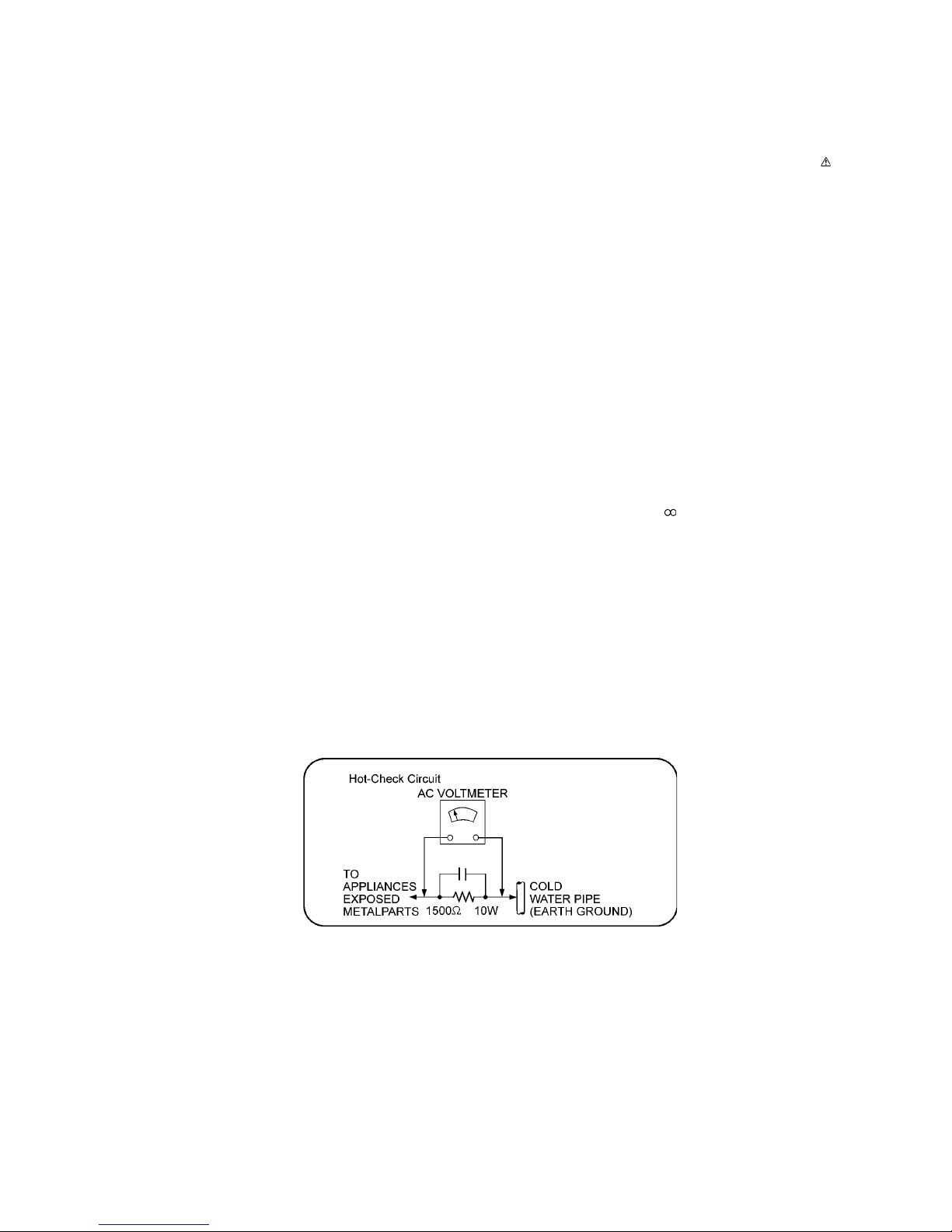
1.1.2. Leakage Current Hot Check
1. Plug the AC cord directly into the AC outlet. Do not use an isolation transformer for this check.
2. Connect a 1.5k:, 10 watts resistor, in parallel with a 0.15PF capacitors, between each exposed metallic part on the set and a
good earth ground such as a water pipe, as shown in Figure 1-1.
3. Use an AC voltmeter, with 1000 ohms/volt or more sensitivity, to measure the potential across the resistor.
4. Check each exposed metallic part, and measure the voltage at each point.
5. Reverse the AC plug in the AC outlet and repeat each of the above measurements.
6. The potential at any point should not exceed 0.75 volts RMS. A leakage current tester (Simpson Model 229 or equivalent)
may be used to make the hot checks, leakage current must not exceed 1/2 milliamp. In case a measurement is outside of the
limits specified, there is a possibility of a shock hazard, and the equipment should be repaired and rechecked before it is
returned to the customer.
Figure 1-1
1.2. Before Repair and Adjustment
Disconnect AC power to discharge the AC Capacitors (C1004, C1005, C1006, C1007, C1013, C1014, C1308, C1752) through a 10
:, 10 W resistor to ground.
Caution:
DO NOT SHORT-CIRCUIT DIR ECTLY (with a screwdriver blade, for instance), as this may destroy solid state devices.
After repairs are completed, restore power gradually using a variac, to avoid overcurrent.
Current consumption at AC 127 V, 60 Hz in FM Tuner at volume minimum should be ~ 850mA.
1.3. Protection Circuitry
The protection circuitry may have operated if either of the following conditions are noticed:
• No sound is heard when the power is turned on.
• Sound stops during a performance.
The function of this circuitry is to prevent circuitry damage if, for example, the positive and negative speaker connection wires are
“shorted”, or if speaker systems with an impedance less than the indicated rated impedance of the amplifier are used.
If this occurs, follow the procedure outlines below:
1. Turn off the power.
2. Determine the cause of the problem and correct it.
3. Turn on the power once again after one minute.
Note:
When the protection circuitry functions, the unit will not operate unless the power is first turned off and then on again.
1.4. Caution For Fuse Replacement
1.5. Safety Parts Information
Safety Parts List:
There are special components used in this equipment which are important for safety.
These parts are marked by in the Schematic Diagrams, Exploded View & Replacement Parts List. It is essential that these
critical parts should be replaced with manufacturer’s specified parts to prevent shock, fire or other hazards. Do not modify the
original design without permission of manufacturer.
!
!
!
!
!
!
!
!
!
!
!
!
!
!
!
D0GF105JA048
ADAPTADOR TOMA CORRIENTE K2DAYYY00002
RQTM0200
RKM0702Z-K
FIXED INDUCTORS G0C400K00001
RESISTOR
VARISTOR D4EAY511A127
CAPACITOR DE AC F0CAF104A105
INSTRUCTIVO
RGR0439L-B1
RD-DDL107-PX
K5G502Y00006
FUSES, LEADED TYPE (CAP
TERMINAL TYPE EXCLUDED )
F1BAF471A013
PCB SMPS
B3PBA0000579
RJB3716A-1
GAB. MET. SIN DOBLAR
REAR PANEL
CAPACITOR DE AC CERAMICO F1BAF221A013
OPTOACOPLADOR
CABLE TOMACORRIENTE.
CONECTOR TOMACORRIENTE
Nombre del componente
K2CR2YY00055
G4DYZ0000076
K5D103BNA005
Numero de Parte
TRANSFORMADOR DE PODER
TRANSFORMADOR DE
RESPALDO
BRS1.1C (CD UNIT)
FUSIBLE PRIMARIO
CAPACITOR DE AC
CAPACITOR DE AC CERAMICO
F0CAF224A105
K2AZYA000005
G4DYA0000520
FUSES, LEADED TYPE (CAP
TERMINAL TYPE EXCLUDED )
K5G501YA0081
GAB. MET. DOBLADO RXRM0003
!
!
!
!
!
!
!
Safety
2 Warning
2.1. Prevention of Electrostatic Discharge (ESD) to Electrostatically Sensi-
tive (ES) Devices
Some semiconductor (solid state) devices can be damaged easily by static electricity. Such components commonly are called Electrostatically Sensitive (ES) Devices.
The following techniques should be used to help reduce the incidence of component damag e caused by electrostatic discharge
(ESD).
1. Immediately before handling any semiconductor component or semiconductor-equipped assembly, drain off any ESD on your
body by touching a known earth ground. Alternatively, obtain and wear a commercially available discharging ESD wrist strap,
which should be removed for potential shock reasons prior to applying power to the unit under test.
2. After removing an electrical assembly equippe d with ES devices, place the assembly on a conductive surface such as aluminum foil, to prevent electrostatic charge buildup or exposure of the assembly.
3. Use only a grounded-tip soldering iron to solder or unsolder ES devices.
4. Use only an anti-static solder removal device. Some solder removal devices not classified as “anti-static (ESD protected)” can
generate electrical charge sufficient to damage ES devices.
5. Do not use freon-propelled chemicals. These can generate electrical charges sufficient to damage ES devices.
6. Do not remove a replacement ES device from its protective package until immediately before you are ready to install it. (Most
replacement ES devices are packaged with leads electrically shorted together by conductive foam, aluminum foil or comparable conductive material).
7. Immediately before removing the protective material from the leads of a replacement ES device, touch the protective material
to the chassis or circuit assembly into which the device will be installed.
CAUTION:
Be sure no power is applied to the chassis or circuit, and observe all other safety precautions.
8. Minimize bodily motions when handling unpackaged replacement ES devices. (Otherwise harmless motion such as the
brushing together of your clothes fabric or the lifting of your foot from a carpeted floor can generate static electricity (ESD) sufficient to damage an ES device).

2.2. Precaution of Laser Diode
Caution:
This product utilizes a laser diode with the unit turned “on”, invisible laser radiation is emitted from the pickup lens.
Wavelength: 790 nm (CD)
Maximum output radiation power from pickup: 100 W/VDE
Laser radiation from the pickup unit is safety level, but be sure the followings:
1. Do not disassemble the pickup unit, since radiation from exposed laser diode is dangerous.
2. Do not adjust the variable resistor on the pickup unit. It was already adjusted.
3. Do not look at the focus lens using optical instruments.
4. Recommend not to look at pickup lens for a long time.
2.3. Service caution based on Legal restrictions
2.3.1. General description about Lead Free Solder (PbF)
The lead free solder has been used in the mounting process of all electrical components on the printed circuit boards used for this
equipment in considering the globally environmental conservation.
The normal solder is the alloy of tin (Sn) and lead (Pb). On the other hand, the lead free solder is the alloy mainly consists of tin
(Sn), silver (Ag) and Copper (Cu), and the melting point of the lead free solder is higher approx.30 degrees C (86qF) more than that
of the normal solder.
Definition of PCB Lead Free Solder being used
Service caution for repair work using Lead Free Solder (PbF)
• The lead free solder has to be used when repairing the equipment for which the lead fre e solder is used.
(Definition: The letter of “PbF” is printed on the PCB using the lead free solder.)
• To put lead free solder, it should be well molten and mixed with the original lead free solder.
• Remove the remaining lead free solder on the PCB cleanl y for soldering of the new IC.
• Since the melting point of the lead free solder is higher than that of the no rmal lead solder, it takes the longer time to melt the
lead free solder.
• Use the soldering iron (more than 70 W) equipped wi th the temp erature contro l after setting the temp erature at 350±30 degrees
C (662±86qF).
Recommended Lead Free Solder (Service Parts Route.)
• The following 3 types of lead free solder are available through the service parts route.
RFKZ03D01K-----------(0.3mm 100g Reel)
RFKZ06D01K-----------(0.6mm 100g Reel)
RFKZ10D01K-----------(1.0mm 100g Reel)
Note
* Ingredient: tin (Sn), 96.5%, silver (Ag) 3.0%, Copper (Cu) 0.5%, Cobalt (Co) / Germanium (Ge) 0.1 to 0.3%
The letter of “PbF” is printed either foil side or components side on the PCB using the lead free solder.
(See right figure)
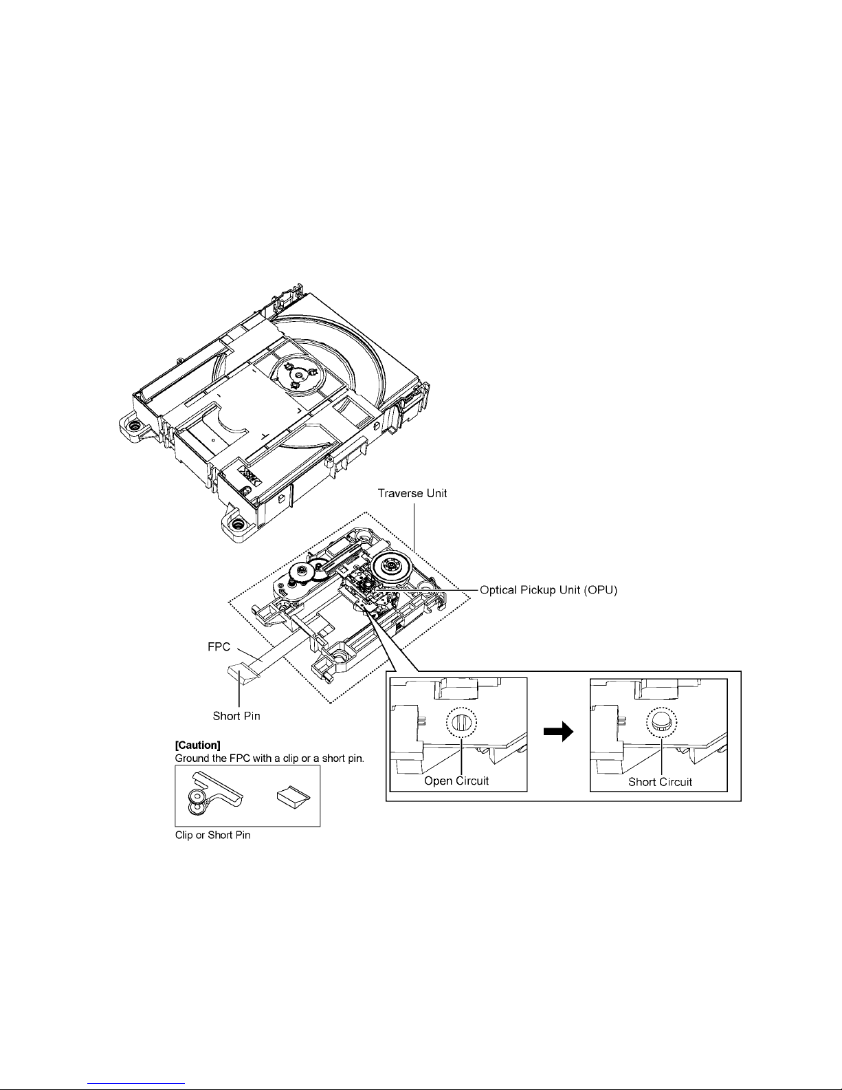
2.4. Handling Precautions for Traverse Ass’y
The laser diode in the optical pickup unit may break down due to static electricity of clothes or human body. Special care must be
taken avoid caution to electrostatic breakdown when servicing and handling the laser diode in the traverse unit.
2.4.1. Cautions to Be Taken in Handling the Optical Pickup Unit (OPU)
The laser diode in the optical pickup unit may be d amaged due to electrostatic discharge g enerating from clothes or human body.
Special care must be taken avoid caution to electrostatic discharge damage when servicing the laser diode.
1. Do not give a considerable shock to the optical pickup unit as it has an extremely high-precise structure.
2. To prevent the laser diode from the electrostatic discharge damage, the flexible cable of the optical pickup unit removed
should be short-circuited with a short pin or a clip.
3. The flexible cable may be cut off if an excessive force is applied to it. Use caution when handling the flexibl e cable.
4. The antistatic FPC is connected to the new optical pickup unit. After replacing the optical pickup unit and connecting the flexible cable, cut off the antistatic FPC.
Figure 2-2
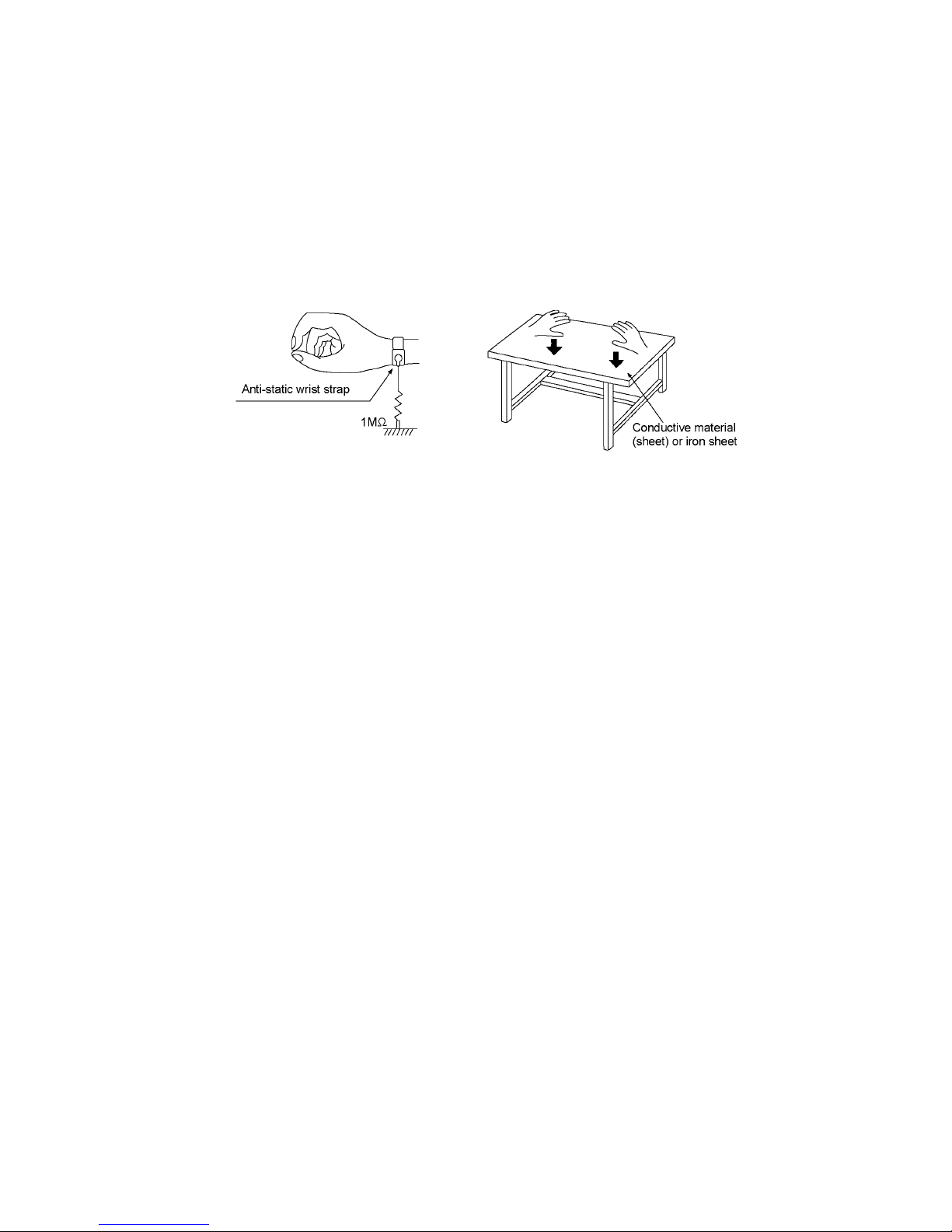
2.5. Grounding for electrostatic breakdown prevention
• As for parts that use optical pick-up (laser diode), the optical pick-up is destroyed by the static electricity of the working environment.
Repair in the working environment that is grounded.
2.5.1. Worktable grounding
• Put a conductive material (sheet) or iron sheet on the area where the optical pickup is placed and ground the sheet.
2.5.2. Human body grounding
• Use the anti-static wrist strap to discharge the static electricity form your body Figure 2-3.
Figure 2-3
3 Service Navigation
3.1. Service Information
This service manual contains technical information which will allow service personnel’s to understand and service this model.
Please place orders using the parts list and not the drawing reference numbers.
If the circuit is changed or modified, this information will b e followe d by supplemen t service ma nual to be filed with original service
manual.
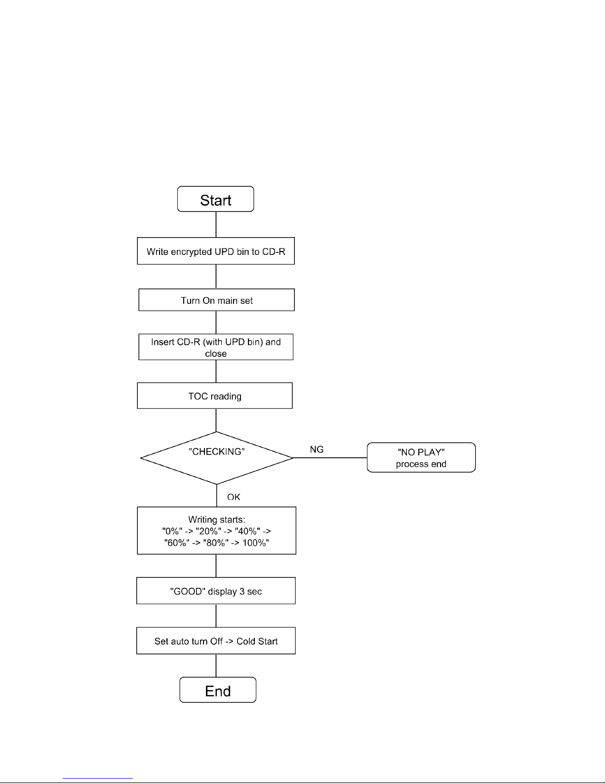
3.2. Firmware Update Procedure
Figure 3-1

4 Specifications
Potencia total PMPO 31350 W
Sección del sintonizador, terminales
Memoria preconfigurada 30 emisoras de FM
15 emisoras de AM
Frecuencia modulada (FM)
Gama de frecuencias
87,5 MHz a 108,0 MHz (en pasos de 100 kHz)
87,9 MHz a 107,9 MHz (en pasos de 200 kHz)
Terminales de la antena 75 (desbalanceado)
Amplitud modulada (AM)
Gama de frecuencias
520 kHz a 1710 kHz (en pasos de 10 kHz)
Conector del micrófono
k1.1,Vm7,0dadilibisneS
Terminal Mono, toma de 3,5 mm (1 sistema)
Puerto de música (frontal)
Sensibilidad 100 mV, 4,7 k
Terminal Estéreo, toma de 3,5 mm
Entrada AUX Clavija jack
Sección de discos compactos
Discos reproducidos (8 cm o 12 cm)
CD, CD-R/RW (CD-DA, MP3 )
Lector
)DC(mn097adnoeddutignoL
Salida de audio (disco)
Número de canales 2.2 canales (FL, FR, SW)
FL = Canal frontal izquierdo
FR = Canal frontal derecho
SW = Canal de subwoofer
MPEG-1 Layer 3
Sección de memoria interna
Memoria
Tamaño de la memoria 4 GB
Compatibilidad con formato de archivos de medios
MP3 (*.mp3)
Grabación en memoria interna
Velocidad de bits 128 kbps
Velocidad de grabación en la memoria
1x, 3x máx. (CD solamente)
Formato de archivo de grabación MP3 (*.mp3)
Capacidad de total de canciones grabadas
(usa 128 kbps, aproximadamente 1 canción = 4 minutos)
1000 canciones
Sección de USB
Puerto USB
USB estándar USB 2.0 velocidad total
Compatibilidad con formato de archivos de medios
MP3 (*.mp3)
Sistema de archivo de dispositivo USB
FAT12 , FAT1 6, FAT 32
Energía puerto USB 500 mA (máx.)
Velocidad de bits
16 kbps a 320 kbps (reproducción)
Grabación en USB
spbk821stibeddadicoleV
Velocidad de grabación USB
1x, 3x máx. (CD solamente)
Formato de archivo de grabación MP3 (*.mp3)
Sección de Bluetooth
®
Especificación del sistema de Bluetooth
®
V3,0
Clasificación del equipo inalámbrico Clase 2
Perfiles admitidos A2DP, AVRCP, GAVDP
Banda de frecuencia 2402 MHz a 2480 MHz
(Salto de frecuencia adaptativa)
Distancia de conducción 10 m de la línea de visión
Sección de bafles
Tipo Sistemade4bocinasde4vías
(reflejo de sonidos graves)
Bocina(s)
Súper Woofer (Bajo) Tipo cónico de 38 cm
Súper Woofer (Medio bajo) Tipo cónico de 20 cm
Bocina para graves Tipo cónico de 10 cm
Bocina para agudos Tipo cónico de 6 cm
Impedancia
Alto 3
/ Medio bajo 3
/ Bajo 6
Presión acústica de salida 93 dB/W (1 m)
Gama de frecuencias 38 Hz a 23 kHz (–16 dB)
44 Hz a 18 kHz (–10 dB)
Dimensiones (An x Al x Prf)
558 mm x 796 mm x 525 mm
Peso 34,2 kg
Generalidades
Fuente de alimentación
~
127V,60Hz
Consumo de energía 220 W
Dimensiones (An x Al x Prf)
485 mm x 231 mm x 378 mm
Peso 5,3 kg
Gama de temperaturas de funcionamiento
0°C a +40°C
Gama de humedades de funcionamiento
35% a 80% humedad relativa (sin condensación)
Nota:
Las especificaciones están sujetas a cambios sin
previo aviso.
El peso y las dimensiones son aproximados.
La distorsión armónica total se mide con el analizador
de espectro digital.
Sección del amplificador
Potencia de salida RMS en modo estéreo
Alto 350 W por canal (3 ), 1 kHz, 30% THD
Medio bajo 350 W por canal (3 ), 1 kHz, 30% THD
Bajo 725 W por canal (6 ), 100 Hz, 30% THD
Potencia total del modo estéreo RMS
2850 W (30% THD)
Consumo en el modo normal
Consumo en el modo de espera
220Wh/día (considerando 1 hora de uso al día).
6,9Wh/día (considerando 23 horas en modo de espera
al día).
5 General/Introduction
5.1. Media Information
6 Location of Controls and Components
6.1. Remote Control Key Button Operation
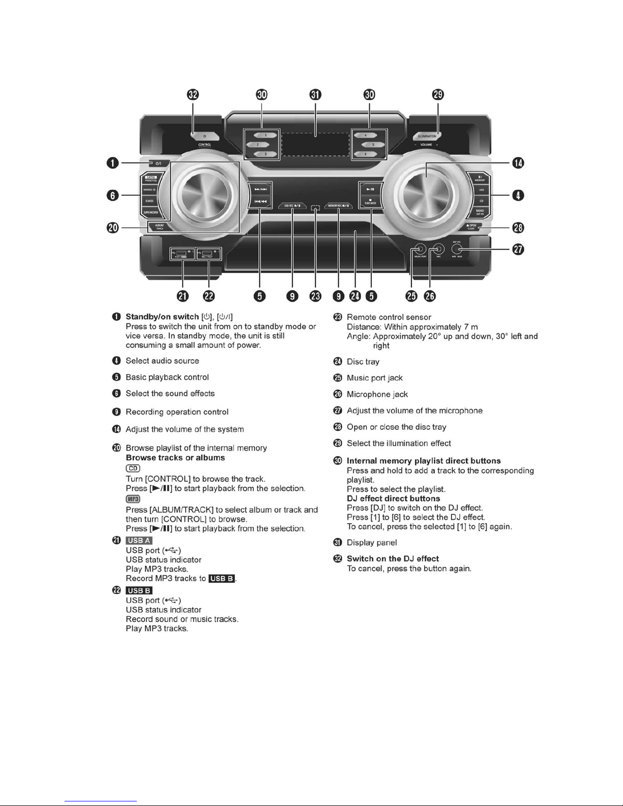
6.2. Main Unit Key Button Operation

7 Service Mode
7.1. Cold-Start
Here is the procedure to carry out cold-start or initialize to shipping mode.
1. Unplug AC power cord
2. Press & hold [POWER] button
3. Plug AC power cord while [POWER] button being pressed
FL Display will show “_ _ _ _ _ _ _ _”
4. Release [POWER] button
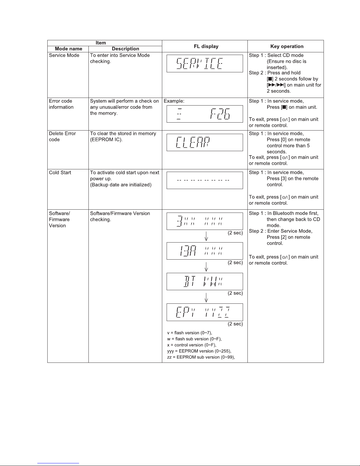
7.1.1. Service Mode Table
7.2. Doctor Mode Table
7.2.1. Doctor Mode Table 1
FL Display
Key Operation
Front Key
Item
DescriptionMode Name
Doctor Mode
EEPROM
checksum
check
To enter into Doctor Mode In CD Mode:
1. Press [ ] button on
main unit follow by [4]
and [7] on remote control.
In CD mode:
1. Enter into Doctor Mode
2. To exit, press [DELETE]
button on remote control or,
press [POWER, /I] button on
Main Unit
Displaying of
1. Year Develop.
2. Model Type.
3. ROM Type.
4. Firmware Version.
(Display 1)
Version No. (001 ~ 999) specific for each
firmware
(Decimal)1 2 3 4
7.2.2. Doctor Mode Table 2
FL Display
Key Operation
Front Key
Item
DescriptionMode Name
Volume Setting
Check
FL Display Check
To check the volume setting of the
unit.
To check the FL segment display.
All segments will light up while all LED
blink at 0.5s intervals.
In Doctor Mode:
1. Press [7], [8], & [9] button on
the remote control.
In Doctor mode:
1. Press [1] button on the
remote control.
2. To cancel this mode, press
[0] button on the remote control.
Press [7]: VOL50
Press [8]: VOL35
Press [9]: VOL0
Volume
In this mode, the tray will open & close
automatically.
Cancellation Display
CD Loading Test To determine the open & close
operation of the CD Mechanism Unit.
Note: Refer to Section 7.3 for process
flow.
Note: Refer to Section 7.3 for process
flow.
Note: Refer to Section 7.3 for process
flow.
The counter will
increment by one.
When reach 99999999
will change to 00000000
Cancellation Display
Traverse Test To determine the traverse unit
operation for inner & outer track access.
The counter will
increment by one.
When reach 99999999
will change to 00000000
The counter will
increment by one.
When reach 99999999
will change to 00000000
Cancellation Display
Reliability Test
(Combination of
Traverse & CD
Loading Test)
In this mode,ensure the CD is in the
unit.
Note:
To determine the traverse unit
operation & open/close operation of the
mechanism.
In this mode,ensure the CD is in the
main unit.
In Doctor Mode:
1. Press [10] [2] [1] button
on the remote control.
In Doctor Mode:
2. To cancel this mode, press
[0] button on the remote control.
1. Press [10] [1] [2] button
on the remote control.
In Doctor Mode:
1. Press [10] [1] [5] button
on the remote control.
2. To cancel this mode, press
[0] button on the remote control.
2. To cancel this mode, press
[0] button on the remote control.
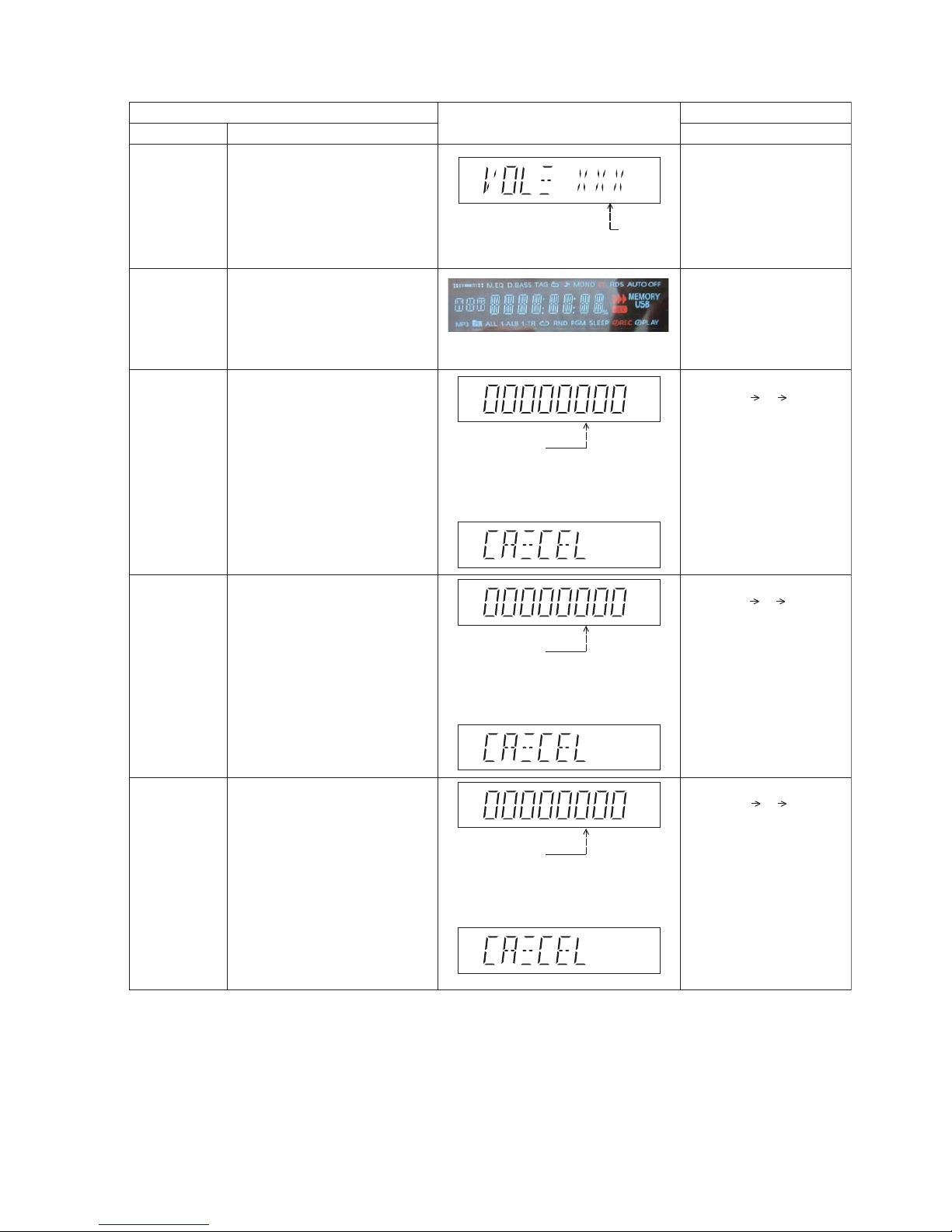
7.2.3. Doctor Mode Table 3
FL Display
Key Operation
Front Key
Item
DescriptionMode Name
CD
Self- Adjustment
Test
To display result of
self-adjustment for CD operation.
CD LSI Version
Check
To check the CD LSI Version and
its checksum.
In Doctor Mode
:
1. Press [10] [1] [4] button
on the remote control.
In Doctor Mode:
1. Press [4] button on the
remote control.
Display of auto adjustment
result
Reference table:
ERROR Code
Status
Condition
0 1 2 4 6 8 A C E F
AOC1/AOC2 O O O O O O O O -
ABC2/ABC1 O - X O X O X O X -
2
nd
AOC1 O - O X X O O X X -
FAGC/TAGC O - O O O X X X X -
AGC2 O - O O O O O O O
O : OK;
X : NG (In case that time out happens.)
: Either one of FO AOC, TR AOC and FO
coarse AGC is NG.
: If the AGC is NG (ignore others).
To cancel this mode, press [0]
button on the remote control.
To cancel this mode, press [0]
button on the remote control.
(Display 2)
(Display 1)
Version (Decimal)
ROM
Type
Year Develop
after
2 sec
Checksum (Hex)
Bluetooth
Version Check
Bluetooth module will need some
time to power up and read the
version display.
Meanwhile [_BT_ll----_] will show
before the ver. numbers appear.
2s display count should start after
flash version number appear.
Bluetooth Check 1. Bluetooth device will start
pairing.
2. Once connected it wll autoplay
for 5 sec and auto disconect.
( 2 sec)
1. Go to Bluetooth selector and
enter Doctor Mode.
1. Go to Bluetooth selector and
enter Doctor Mode.
2. Press USB[O/II] on remote
control.
3. Device will display
SC-MAX250-X,
SC-MAX150-X.
(X = region number)
( 2 sec)
v = flash version (0~7),
w = flash sub version (0~F),
x = control version (0~F),
yyy = EEPROM version (0~255),
zz = EEPROM sub version (0~99),
2. Press [10] [2] [4] and
display will show.

7.3. Reliability Test Mode (CD Mechanism Unit)
Below is the process flow chart of the aging test for the CD Mechanism Unit .
Fig. 7-1. Reliability Test (Loading)
Fig. 7-2. Reliability Test (Traverse)
Fig. 7-3. Reliability Test (Combination)
OPEN
Operation
OPEN wait
for 1 s
CLOSE
Operation
CLOSE wait
for 4 s
Count up
First Track
Access
First Track
Play 5 s
Last Track
Access
Last Track
Play 5 s
Count up
First Track
Access
Access
Play 10 s
Open
Operation
Open wait
for 1 s
CLOSE
Operation
Count up
First Track
Last Track
Last Track
Play 10 s
7.4. Self-Diagnostic Mode
7.5. Self-Diagnostic Error Code Table
Self-Diagnostic Function (Refer Section 7.4. Self-Diagnostic Mode) provides information on any problems occurring for the unit and
its respective components by displaying the error codes. These error code such as U**, H** and F** are stored in memory and held
unless it is cleared.
The error code is automatically display after entering into self-diagnostic mode.
7.5.1. Power Supply Error Code Table
FL Display
Key Operation
Front Key
Item
Description
Mode Name
To enter into self diagnostic checking
System will perform a check on any
unusual/error code from the memory
To clear the stored in memory
(EEPROM IC)
Self Diagnostic
Mode
Error code
information
Delete error
code
Step 1: Select CD mode
(Ensure no disc is inserted).
Step 2: Press & hold [ ] button
follow by [ ] on
main unit for 2 seconds.
Step 1: In self diagnostic mode,
Press [ ] on main unit.
To
unit or remote control.
Step 1: In self diagnostic mode,
Press [0] on remote control.
To
unit or remote control.
Example:
/
Cold Start To active cold start upon next AC
power up when reset start is
execute the next time.
In self diagnostic mode:
1. Press [3] button on
the remote control.
exit, press [ /I] on main
exit, press [ /I] on main
7.5.2. CD Mechanism Error Code Table (CD Mechanism Unit)
7.6. Sales Demonstration Lock Function
7.6.1. Entering into Sales demonstration lock mode
Here is the procedures to enter into the Sales demonstration lock mode.
Step 1: Turn on the unit.
Step 2: Select to any mode function.
Step 3: Press and hold [
OPEN/CLOSE] and [CD] keys for 5 sec or more.
The display will show upon entering into this mode for 2 sec.
Note: [
OPEN/CLOSE] button is invalid and the main unit displays “LOCKED” while the lock function mode is entered.
7.6.2. Cancellation of Sales demonstration lock mode
Step 1: Turn on the unit.
Step 2: Select to any mode function.
Step 3: Set volume to Vol 19.
Step 4: Press and hold [
OPEN/CLOSE] and [CD] keys for 5 sec or more.
The display will show upon entering into this mode for 2 sec.
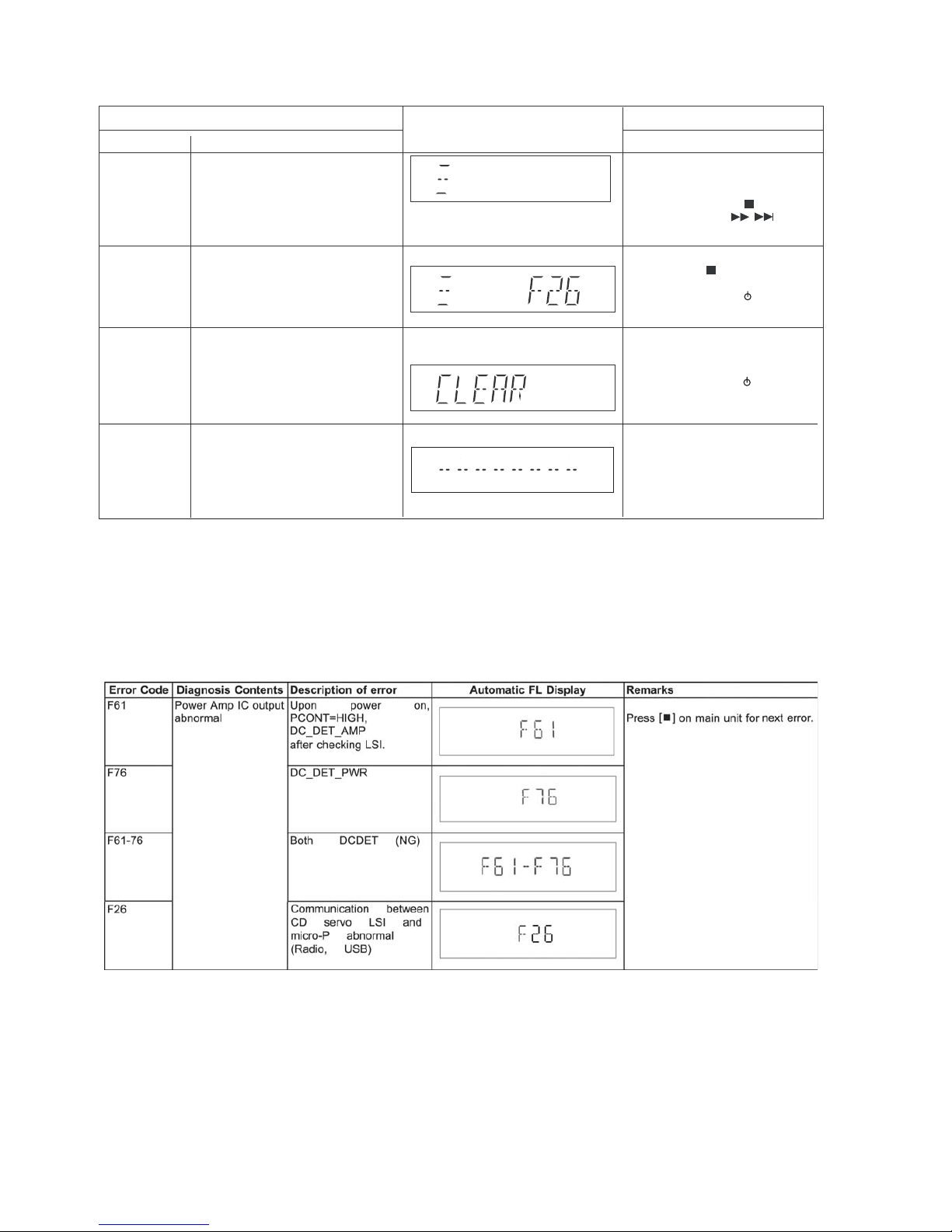
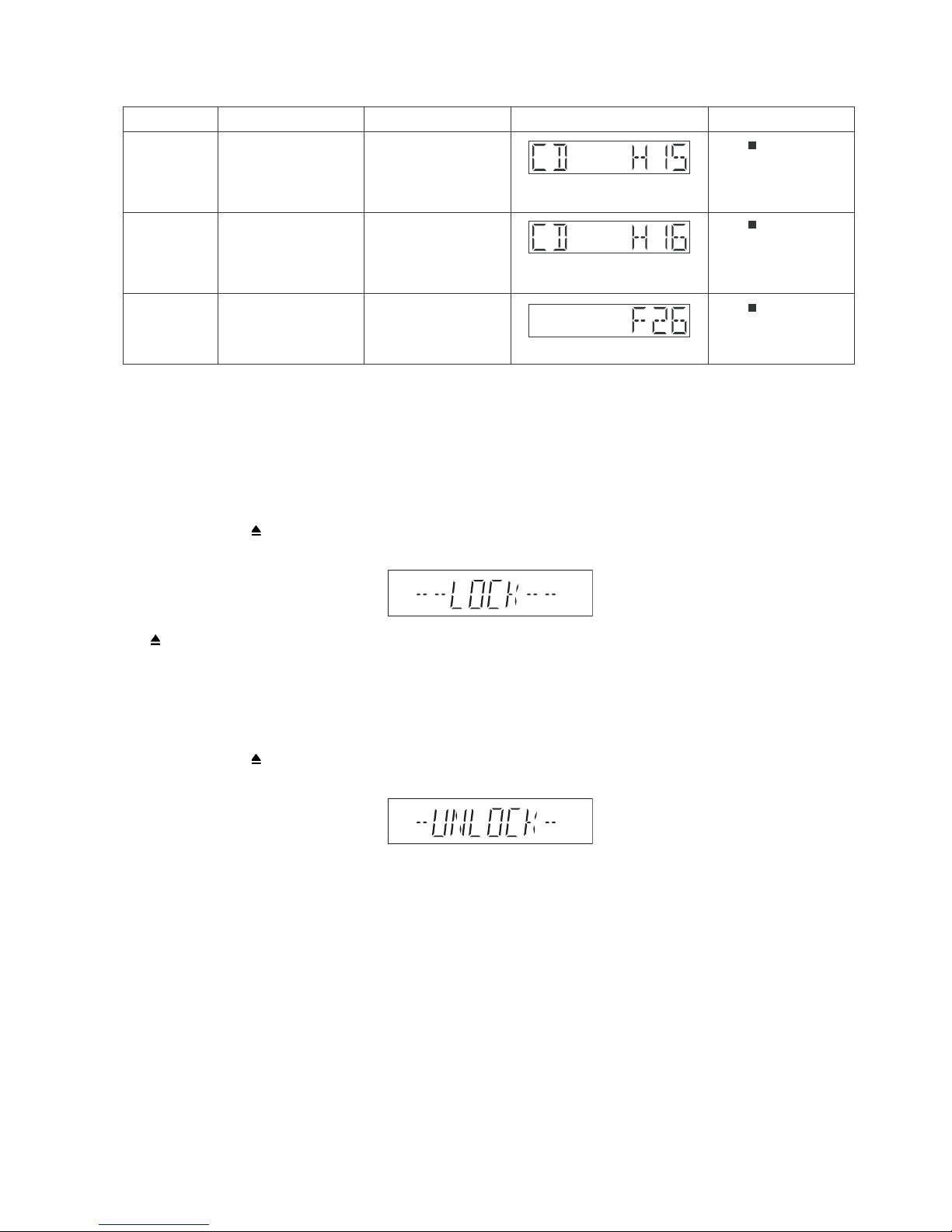
Error Code Diagnostic Contents Description of error Automatic FL Display Remarks
CD H15 CD Open Abnormal During operation
POS_SW_R On fail to be
detected with 4 sec. Error
No. shall be clear by force
or during cold start.
Press [
] on main unit for
next error.
CD H16 CD Closing Abnormal During operation
POS_SW_CEN On fail to
be detected with 4 sec.
Error No. shall be clear by
force or during cold start.
Press [
] on main unit for
next error.
F26 Communication between
CD servo LSI and micro-p
abnormal.
During switch to CD function, if SENSE = “L” within
failsafe time of 20ms.
Press [
] on main unit for
next error.

8 Troubleshooting Guide
"Contents for this section is not available at time of issue"
9 Disassembly and Assembly Instructions
Caution Note:
• This section describes the disassembly and/or assembl y procedures for all ma jor printed circuit boards & main components for
the unit. (You may refer to the sectio n of “Main components and P.C.B Locations” as described in the service manual)
• Before carrying out the disassembly process, please ensure all the safety precautions & procedures are followed.
• During the disassembly and/or assembly proc ess, please handle with care as there may be chassis components with
sharp edges.
• Avoid touching heatsinks due to its high temperature after prolong use. (See caution as described below)
• During disassembly and assembly, please ensure proper service tools, equipments or jigs is being used.
• During replacement of component parts, please refer to the section of “Replacement Parts List” as described in the service manual.
• Select items from the following indexes when disassembly or replacement are required.
• Disassembly of Top Cabinet
• Disassembly of Front Panel Unit
• Disassembly of FL Display P . C.B.
• Disassembly of Bluetooth P.C.B.
• Disassembly of Illumination Button P.C.B.
• Disassembly of Control P.C.B.
• Disassembly of Control Jog LED P.C.B.
• Disassembly of Volume P.C.B.
• Disassembly of Volume Jog LED P .C.B.
• Disassembly of Remote Sensor P.C.B.
• Disassembly of USB P.C.B.
• Disassembly of Mic P.C.B.
• Disassembly of LED P.C.B.
• Disassembly of CD Lid
• Disassembly of Rear Panel
• Disassembly of CD Mechanism Unit
• Disassembly of Main P.C.B.
• Disassembly of SMPS P.C.B.
• Disassembly of Tuner P.C.B.
• Disassembly of CD Interface P.C.B.
9.1. Screw Types

9.2. Disassembly Flow Chart
9.4. Top Cabinet
9.5. Front Panel Unit
9.6. FL Display P.C.B.
9.9. Control P.C.B.
9.10. Control Jog LED
P.C.B.
9.8. Illumination
Button P.C.B.
9.12. Volume Jog LED
P.C.B.
9.13. Remote Sensor
P.C.B.
9.11. Volume P.C.B.
9.14. USB P.C.B.
9.15. Mic P.C.B.
9.16. LED P.C.B.
9.17. CD Lid
9.19. CD Mechanism
Unit
P.C.B.
9.20. Main P.C.B.
9.21. SMPS P.C.B.
9.22. Tuner P.C.B.
9.18. Rear Panel
9.23. CD Interface
9.7. Bluetooth P.C.B.
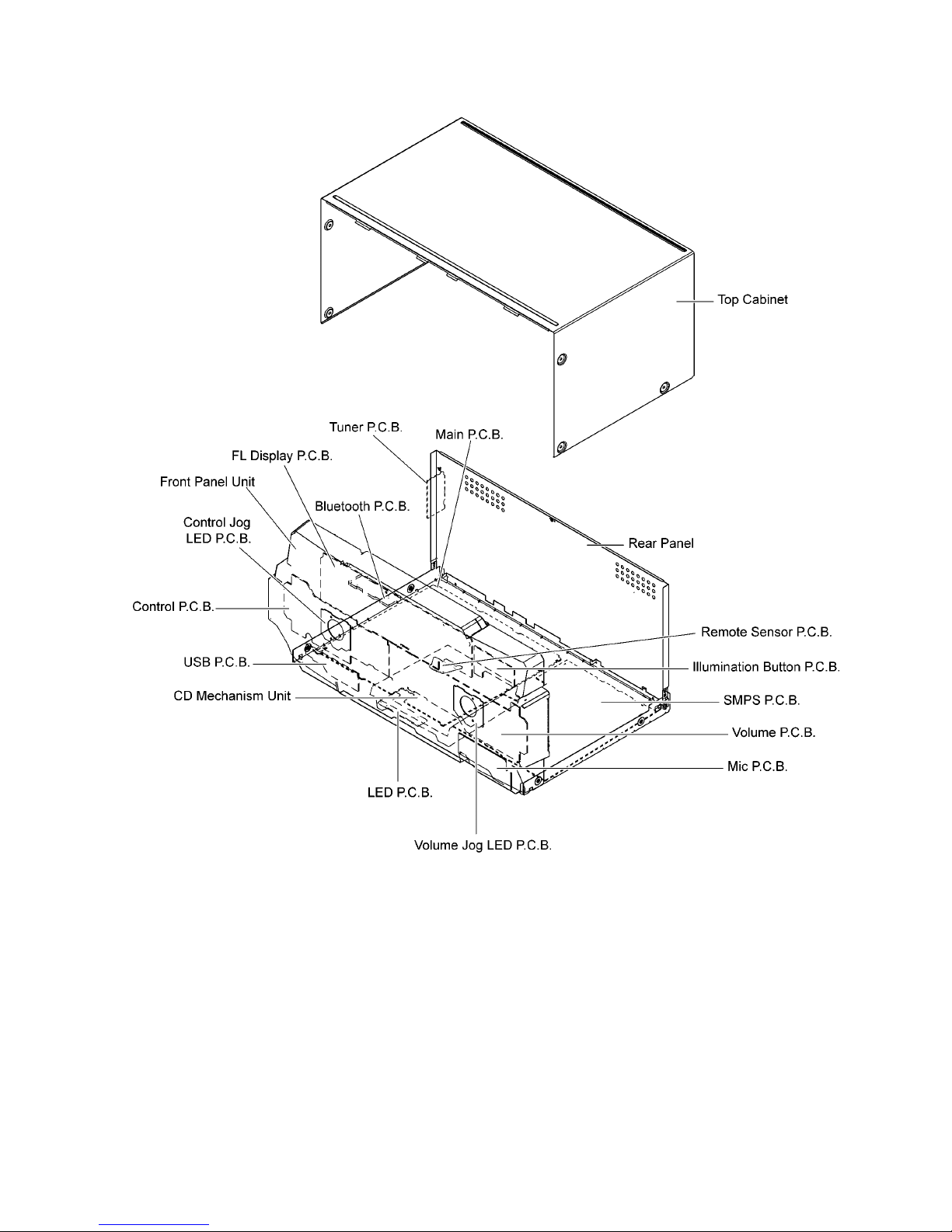
9.3. Main Components and P.C.B. Locations
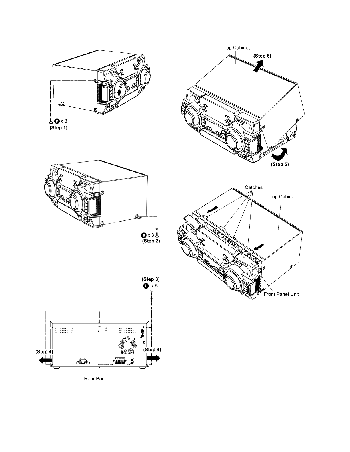
9.4. Disassembly of Top Cabinet
Step 1 Remove 3 screws.
Step 2 Remove 3 screws.
Step 3 Remove 5 screws.
Step 4 Slightly release both sides of the Top Cabinet as arrow
shown.
Step 5 Slightly lift up the Top Cabinet.
Step 6 Remove the Top Cabinet.
Caution: During assembling, ensure that the Top Cabinet
is located & inserted into the Front Panel Unit as shown.
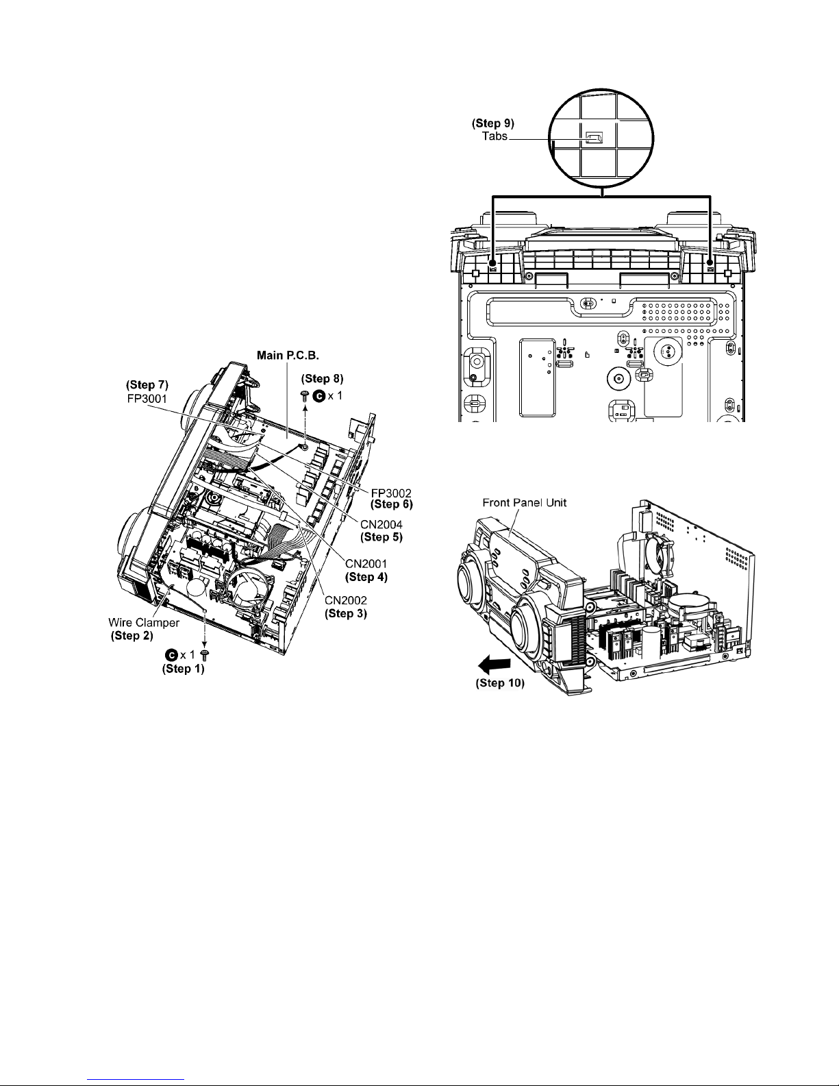
9.5. Disassembly of Front Panel
Unit
• Refer to “Disassembly of Top Cabinet”.
Step 1 Remove 1 screw.
Step 2 Remove the Wire Clamper.
Step 3 Detach 10P FFC at the connector (CN2002) on Main
P.C.B..
Step 4 Detach 11P Cable at the co nnector (CN2001) on Main
P.C.B..
Step 5 Detach 30P FFC at the connector (CN2004) on Main
P.C.B..
Step 6 Detach 10P FFC at the connector (FP3002) on Main
P.C.B..
Step 7 Detach 5P Wire at the connector (FP3001) on Main
P.C.B..
Step 8 Remove 1 screw.
Step 9 Release tabs at the bottom of the unit.
Step 10 Detach to remove the Front Panel Unit
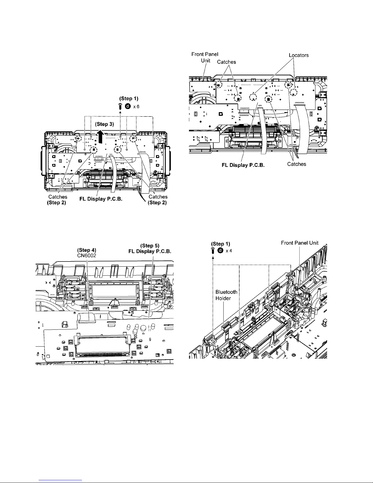
9.6. Disassembly of FL Display
P.C.B.
• Refer to “Disassembly of Top Cabinet”.
• Refer to “Disassembly of Front Panel Unit”.
Step 1 Remove 6 screws.
Step 2 Release catches.
Step 3 Lift up the FL Display P.C.B..
Step 4 Detach 30P FFC at the connector (CN6002) on FL Dis-
play P.C.B..
Step 5 Remove the FL Display P.C.B..
Caution: During assembling, ensure that the FL Display
P.C.B. is properly located and fully catched onto the Front
Panel Unit.
9.7. Disassembly of Bluetooth
P.C.B.
• Refer to “Disassembly of Top Cabinet”.
• Refer to “Disassembly of Front Panel Unit”.
• Refer to “Disassembly of FL Display P.C.B.”.
Step 1 Remove 4 screws.
 Loading...