

Panasonic bb-hca10 Operation Manual
Installation Guide
Ceiling Flush Mount Bracket
Indoor Use Only
Please read this document before using the product, and save this
document for future reference.
Panasonic Network Camera Website:
http://panasonic.net/pcc/ipcam/
for customers in the USA and Puerto Rico
Model No.
BB-HCA10A
Please read the Operating Instructions included with the camera before proceeding.
• This document (Installation Guide) explains how to install the BB-HCM527A Network Camera using the Ceiling Flush Mount Bracket, and install the bracket in
a ceiling.
Abbreviations
• The Ceiling Flush Mount Bracket is referred to as “the bracket” in this document.
• The Network Camera is referred to as “the camera” in this document.
Preparation
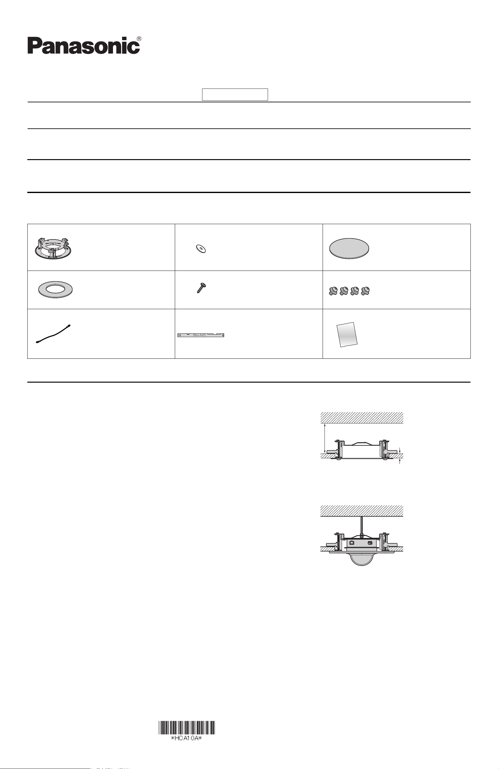
1. Confirm the following items are included in the bracket’s packaging.
• Additional pieces can be ordered by calling 1-800-332-5368.
Ceiling Flush Mount Bracket
(1 pc.)
Ceiling Mounting Cover (1 pc.)
Order No. PQKL10092Z1
Used when mounting the camera
on a ceiling.
Safety Wire (1 pc.)
Order No. PQME10080Z
Used to secure the bracket when
mounting it.
Washer (1 pc.)
Order No. XWG4F16VW
Used when securing the safety
wire to the ceiling.
Screw A (1 pc.)
Order No. XTB4+20AFJ
Used to secure the safety wire to
the ceiling.
Connector Cover (1 pc.)
Order No. PNHX1058Z
Used to protect the cables when
mounting the camera.
Template (1 pc.)
Order No. PNPD1087Z
Used as a references when
making a hole in the ceiling.
Screw B (4 pcs.)
Order No. XYN4+F6FJ
Used to secure the camera
(3 pcs.) and the safety wire (1 pc.)
to the bracket.
Installation Guide
(this document) (1 pc.)
2. You will need the following additional items to install the bracket.
– 1 anchor bolt and 2 nuts (see step 2 and 6 on page 2)
Important Information Regarding Camera Mounting
Please read the following information before mounting the camera. Consult an authorized dealer for mounting.
Caution
• Make sure you attach the safety wire when mounting the bracket and the
camera on a ceiling to prevent them from falling.
Note
• This product should only be used with the BB-HCM527A Network Camera.
• If using an SD memory card, insert the card before installing the camera in
the bracket.
• Use screws that are appropriate for the material of ceiling.
• The included screws are for use with wooden ceilings only.
• To ensure that camera images are displayed properly, do not mount the
bracket on an incline.
• The camera’s MAC address and serial number are printed on the bottom of
the camera and are needed in order for camera configuration and
maintenance. Make a note of both of them for before mounting the camera.
• Mounting and cabling instructions described in this document follow
generally accepted guidelines suitable for residential installations. In some
areas, commercial and industrial installations are regulated by local or state
ordinances. For such installations, contact your local building department or
building inspector for more details.
• Camera images can be viewed in relatively dark areas, however, image
quality decreases when viewing dark images. We recommend using
supplemental lighting for best results.
• Prolonged exposure to direct sunlight or halogen light may damage the
camera’s image sensor. Mount the camera appropriately.
• When mounting the camera, make sure to wrap the AC adaptor cord (if used)
and other cables (external microphone or speaker cable, video cable, etc.)
around the hooks as shown to ensure secure connections.
• Do not directly touch the lens cover. Clean the lens cover with a dry and soft
cloth if necessary.
• There must be at least 80 mm (3 1/8 inches) of space above the ceiling board
where this product will be installed.
• The ceiling board must be no more than 40 mm (1 9/16 inches) thick.
• The illustration below is an example of a completed installation, when looking
at the rear of the camera.
At least 80 mm (3 1/8 inches)
Ceiling board: Max. 40 mm (1 9/16 inches)
© Panasonic System Networks Co., Ltd. 2008
PQQX16477YA KK0108CM1020
Mounting the Bracket and the Camera
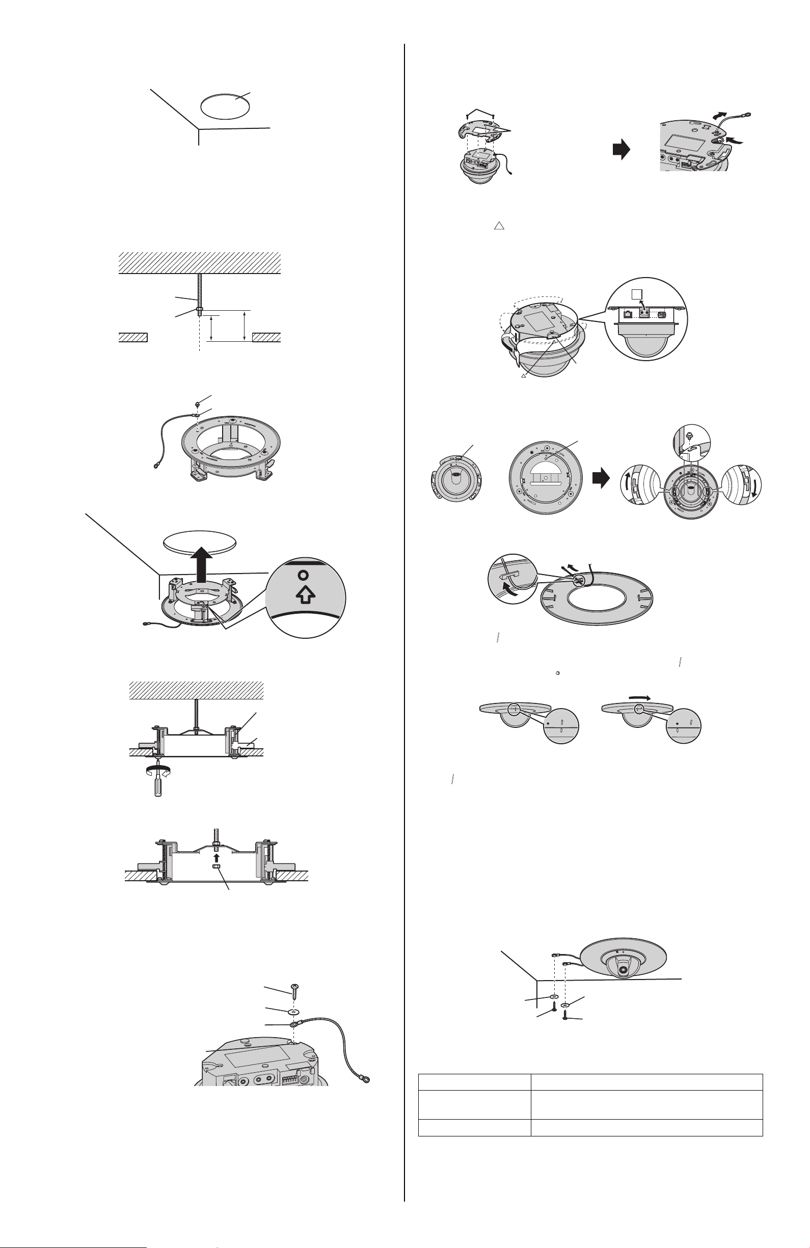
1. Using the included template as a guide, make a hole (φ 240 mm
[9 7/16 inches]) in the ceiling.
Template
2. Drive an anchor bolt (not included) into the original ceiling and attach a
nut (not included) to the bolt.
• Drive the anchor bolt into the original ceiling directly above the center of
the hole made in step 1.
• The end of the anchor bolt should be 47 mm (1 7/8 inches) above the
bottom of the ceiling board.
• The bottom of the nut should be 61 mm (2 3/8 inches) above the bottom
of the ceiling board.
Anchor bolt
8. Align the 2 round protrusions on the camera and the holes on the ceiling
plate (included with the camera), tighten the screw to secure the ceiling
plate, then pass the safety wire through the ceiling plate as shown. Make
sure you do not scratch the lens cover when performing this procedure.
Screw A (2 pcs.) (Length: 20 mm [13/16 inches],
Body diameter: 4.0 mm [3/16 inches])
Holes
9. Attach the connector cover (included) and connect the necessary cables
to the camera.
• Align the “ ” of the connector cover with the center of the recessed
area of the bracket.
• Cut spaces in the connector cover to make room for the cables that will
be connected to the camera. Cut along the perforated lines.
Nut
Ceiling board
Bolt is above center of hole
47 mm
(1 7/8
inches)
61 mm (2 3/8 inches)
3. Secure the safety wire to the bracket using screw B (included).
Screw B
Safety wire
4. Insert the bracket into the hole in the ceiling.
• The camera will face the direction indicated by the arrow on the bracket.
Recessed area
10. Attach the camera to the bracket in 3 places using screw B (included).
• Align the arrows on the ceiling plate (included with the camera) and the
bracket when attaching the camera.
Ceiling plate arrow
Camera direction
11. Secure the ceiling mounting cover (included) to the bracket.
1 Pass the safety wire through the ceiling mounting cover as shown.
5. Tighten the 3 clamp screws (attached to the bracket) and secure the
bracket.
• The clamps tighten as the screws are tightened.
Clamp screw
Clamp
Ceiling board
Clockwise
6. Secure the bracket by attaching and tightening a nut (not included) to the
anchor bolt.
Nut
7. Secure the safety wire (included with the camera) to the camera using
screw B (included with the camera) and washer B (included with the
camera).
• Make sure you attach the safety wire when mounting the camera on a
ceiling to prevent the camera from falling.
2 Align the “ ” marks on the rear of the camera and on the ceiling
mounting cover.
3 Turn the ceiling mounting cover clockwise until the “ ” mark on the rear
of the camera and the “ ” mark on the ceiling mounting cover are
aligned as shown.
• Be careful not to nip the cables, cords, etc.
• To remove the ceiling mounting cover, turn it counterclockwise until the
“ ” mark on the rear of the camera and on the ceiling mounting cover
are aligned, then lower the ceiling mounting cover.
12. Secure the safety wire to the ceiling.
• Secure the bracket’s safety wire first, using screw A and the washer
(included with the bracket), then secure the camera’s safety wire, using
screw A and washer A (both included with the camera).
• Secure the safety wires to the ceiling about 160 mm (6 5/16 inches)
from the center of the camera.
• Do not drive the screws into a soft material. Drive the screws into a
secure, 25 mm (1 inch) thick area of the ceiling, such as a crossbeam,
otherwise the bracket and the camera may fall. If there is no
crossbeam, place a board on the other side of the ceiling to make sure
the bracket and the camera are securely mounted.
(Length: 10 mm [3/8 inches],
Screw B
Body diameter: 2.6 mm [1/8 inches])
Washer B
(Inside diameter: 2.6 mm [1/8 inches])
Safety wire
Safety wire hole
Washer
(Inside diameter:
4.0 mm [3/16 inches])
Screw A
(Length: 20 mm [13/16 inches],
Body diameter: 4.0 mm [3/16 inches])
Washer A
(Inside diameter: 4.0 mm [3/16 inches])
Screw A
(Length: 20 mm [13/16 inches],
Body diameter: 4.0 mm [3/16 inches])
Specifications
Operating temperature +0 °C (+32 °F) to +40 °C (+104 °F)
Dimension (W×H×D) About 270 mm (10 5/8 inches) × 77.5 mm
(3 1/16 inches) × 270 mm (10 5/8 inches)
Weight About 900 g (1.98 lb.)
 Loading...