

Panasonic AW-UE150WP, AW-UE150WE, AW-UE150KP, AW-UE150KE Operating Instructions Manual

DVQP1812ZA
W1118YM0-FJ
ENGLISH
Model No.
AW‑UE150WP
Model No.
AW‑UE150KP
Model No.
AW‑UE150WE
Model No.
AW‑UE150KE
Operating Instructions
4K Integrated Camera
Before operating this product, please read the instructions carefully and save this manual for future use.
Please carefully read the “Read this first!” (pages 2 to 6) of this Manual before use.
PJ
EJ
Read this first! (For AW‑UE150WP, AW‑UE150KP)
CAUTION
RISK OF ELECTRIC SHOCK
DO NOT OPEN
CAUTION: TO REDUCE THE RISK OF ELECTRIC SHOCK,
DO NOT REMOVE COVER (OR BACK).
NO USER SERVICEABLE PARTS INSIDE.
REFER TO SERVICING TO QUALIFIED SERVICE PERSONNEL.
The lightning flash with arrowhead symbol,
within an equilateral triangle, is intended to
alert the user to the presence of uninsulated
“dangerous voltage” within the product’s
enclosure that may be of sufficient magnitude
to constitute a risk of electric shock to
persons.
The exclamation point within an equilateral
triangle is intended to alert the user to
the presence of important operating and
maintenance (servicing) instructions in the
literature accompanying the appliance.
WARNING:
• To reduce the risk of fire or electric shock, do not expose this
equipment to rain or moisture.
• To reduce the risk of fire or electric shock, keep this equipment
away from all liquids. Use and store only in locations which are
not exposed to the risk of dripping or splashing liquids, and do
not place any liquid containers on top of the equipment.
WARNING:
Always keep the main unit mounting screw, bracket mounting
screws and drop-prevention wire mounting screw out of the
reach of infants and small children.
CAUTION:
This apparatus can be operated at a voltage in the range of 100
– 240 V AC.
Voltages other than 120 V are not intended for U.S.A. and
Canada.
Operation at a voltage other than 120 V AC may require the use
of a different AC plug. Please contact either a local or foreign
Panasonic authorized service center for assistance in selecting
an alternate AC plug.
CAUTION:
The mains plug of the power supply cord shall remain readily
operable.
The AC receptacle (mains socket outlet) shall be installed near
the equipment and shall be easily accessible. To completely
disconnect this equipment from the AC mains, disconnect the
power cord plug from the AC receptacle.
CAUTION:
In order to maintain adequate ventilation, do not install or place
this unit in a bookcase, built-in cabinet or any other confined
space. To prevent risk of electric shock or fire hazard due to
overheating, ensure that curtains and any other materials do not
obstruct the ventilation.
CAUTION:
To reduce the risk of fire or electric shock and annoying
interference, use the recommended accessories only.
CAUTION:
Check the installation at least once a year.
An improper installation could cause the unit to fall off resulting
in personal injury.
CAUTION:
Do not pick up and move the unit while the tripod is attached.
The fitting may break under the weight of the tripod, which may
result in injury.
CAUTION:
Naked flame sources, such as lighted candles, should not be
placed on the apparatus.
indicates safety information.
2
FCC NOTICE (USA)
This device complies with part 15 of the FCC Rules.
Operation is subject to the following two conditions:
(1) This device may not cause harmful interference, and (2) this device must accept any interference received, including interference that may
cause undesired operation.
CAUTION:
This equipment has been tested and found to comply with the limits for a class A digital device, pursuant to Part 15 of the FCC Rules.
These limits are designed to provide reasonable protection against harmful interference when the equipment is operated in a commercial
environment. This equipment generates, uses, and can radiate radio frequency energy and, if not installed and used in accordance with the
instruction manual, may cause harmful interference to radio communications.
Operation of this equipment in a residential area is likely to cause harmful interference in which case the user will be required to correct the
interference at his own expense.
FCC Warning:
To assure continued FCC emission limit compliance, follow the attached installation instructions and the user must use only shielded interface
cables when connecting to host computer or peripheral devices. Also, any unauthorized changes or modifications to this equipment could void
the user’s authority to operate this device.
NOTIFICATION (Canada)
CAN ICES-3 (A)/NMB-3(A)
indicates safety information.
IMPORTANT SAFETY INSTRUCTIONS
1) Read these instructions.
2) Keep these instructions.
3) Heed all warnings.
4) Follow all instructions.
5) Do not use this apparatus near water.
6) Clean only with dry cloth.
7) Do not block any ventilation openings. Install in accordance with the manufacturer’s instructions.
8) Do not install near any heat sources such as radiators, heat registers, stoves, or other apparatus (including amplifiers) that produce heat.
9) Do not defeat the safety purpose of the polarized or grounding-type plug. A polarized plug has two blades with one wider than the other. A
grounding-type plug has two blades and a third grounding prong. The wide blade or the third prong are provided for your safety. If the provided plug
does not fit into your outlet, consult an electrician for replacement of the obsolete outlet.
10) Protect the power cord form being walked on or pinched particularly at plugs, convenience receptacles, and the point where they exit from the
apparatus.
11) Only use attachments/accessories specified by the manufacturer.
12) Use only with the cart, stand, tripod, bracket, or table specified by the manufacturer, or sold with the apparatus. When a cart is used,
use caution when moving the cart/apparatus combination to avoid injury from tip-over.
13) Unplug this apparatus during lightning storms or when unused for long periods of time.
14) Refer all servicing to qualified service personnel. Servicing is required when the apparatus has been damaged in any way, such as
power-supply cord or plug is damaged, liquid has been spilled or objects have fallen into the apparatus, the apparatus has been
exposed to rain or moisture, does not operate normally, or has been dropped.
3
Read this first! (For AW‑UE150WP, AW‑UE150KP) (continued)
Read this first! (For AW‑UE150WE, AW‑UE150KE)
WARNING:
• To reduce the risk of fire or electric shock, do not expose this
equipment to rain or moisture.
• To reduce the risk of fire or electric shock, keep this equipment
away from all liquids. Use and store only in locations which are
not exposed to the risk of dripping or splashing liquids, and do
not place any liquid containers on top of the equipment.
WARNING:
Always keep the main unit mounting screw, bracket mounting
screws and drop-prevention wire mounting screw out of the
reach of infants and small children.
CAUTION:
Do not remove panel covers by unscrewing.
To reduce the risk of electric shock, do not remove the covers.
No user serviceable parts inside.
Refer servicing to qualified service personnel.
CAUTION:
The mains plug of the power supply cord shall remain readily
operable.
The AC receptacle (mains socket outlet) shall be installed near
the equipment and shall be easily accessible. To completely
disconnect this equipment from the AC mains, disconnect the
power cord plug from the AC receptacle.
CAUTION:
In order to maintain adequate ventilation, do not install or place
this unit in a bookcase, built-in cabinet or any other confined
space. To prevent risk of electric shock or fire hazard due to
overheating, ensure that curtains and any other materials do not
obstruct the ventilation.
CAUTION:
To reduce the risk of fire or electric shock and annoying
interference, use the recommended accessories only.
CAUTION:
Check the installation at least once a year.
An improper installation could cause the unit to fall off resulting
in personal injury.
CAUTION:
Do not pick up and move the unit while the tripod is attached.
The fitting may break under the weight of the tripod, which may
result in injury.
CAUTION:
Naked flame sources, such as lighted candles, should not be
placed on the apparatus.
indicates safety information.
Turkey Only
AEEE Yönetmeliğine Uygundur.
AEEE Complies with Directive of Turkey.
4

EMC NOTICE FOR THE PURCHASER/USER OF THE APPARATUS
1. Pre‑requisite conditions to achieving compliance with the above standards
<1> Peripheral equipment to be connected to the apparatus and special connecting cables
• The purchaser/user is urged to use only equipment which has been recommended by us as peripheral equipment to be connected to the
apparatus.
• The purchaser/user is urged to use only the connecting cables described below.
<2> For the connecting cables, use shielded cables which suit the intended purpose of the apparatus.
• Video signal connecting cables
Use double shielded coaxial cables, which are designed for 75-ohm type high-frequency applications, for SDI (Serial Digital Interface).
Coaxial cables, which are designed for 75-ohm type high-frequency applications, are recommended for analog video signals.
• Audio signal connecting cables
If your apparatus supports AES/EBU serial digital audio signals, use cables designed for AES/EBU.
Use shielded cables, which provide quality performance for high-frequency transmission applications, for analog audio signals.
• Other connecting cables (IEEE1394, USB)
Use double shielded cables, which provide quality performance for high-frequency applications, as connecting cables.
• When connecting to the DVI signal terminal, use a cable with a ferrite core.
• If your apparatus is supplied with ferrite core(s), they must be attached on cable(s) following instructions in this manual.
2. Performance level
The performance level of the apparatus is equivalent to or better than the performance level required by these standards.
However, the apparatus may be adversely affected by interference if it is being used in an EMC environment, such as an area where strong
electromagnetic fields are generated (by the presence of signal transmission towers, cellular phones, etc.). In order to minimize the adverse
effects of the interference on the apparatus in cases like this, it is recommended that the following steps be taken with the apparatus being
affected and with its operating environment:
1. Place the apparatus at a distance from the source of the interference.
2. Change the direction of the apparatus.
3. Change the connection method used for the apparatus.
4. Connect the apparatus to another power outlet where the power is not shared by any other appliances.
5
Read this first! (For AW‑UE150WE, AW‑UE150KE) (continued)
Disposal of Old Equipment
Only for European Union and countries with recycling systems
This symbol on the products, packaging, and/or accompanying documents means that used electrical and electronic products must not
be mixed with general household waste.
For proper treatment, recovery and recycling of old products, please take them to applicable collection points in accordance with your
national legislation.
By disposing of them correctly, you will help to save valuable resources and prevent any potential negative effects on human health
and the environment. For more information about collection and recycling, please contact your local municipality, dealer or supplier.
Penalties may be applicable for incorrect disposal of this waste, in accordance with national legislation.
Інформація для покупця
Виробник: Panasonic Corporation Панасонік Корпорейшн
Адреса виробника: Kadoma, Osaka, Japan Кадома, Осака, Японія
Країна походження: Japan Японія
Імпортер: ТОВ "ПАНАСОНІК УКРАЇНА ЛТД"
Адреса імпортера: провулок Охтирський, будинок 7, місто Київ, 03022, Україна
Примітки:
Термін служби виробу 7 років
Дата виготовлення може бути визначена за допомогою комбінації літер та цифр серійного номера, розташованого на продукті.
Приклад: X X XXXXXXX
Рік: остання цифра року (7 – 2017, 8 – 2018,…0 – 2020)
Місяць: А – Січень, В – Лютий… L – Грудень
Manufactured by: Panasonic Corporation, Osaka, Japan
Importer’s name and address of pursuant to EU rules:
Panasonic Marketing Europe GmbH
Panasonic Testing Centre
Winsbergring 15, 22525 Hamburg, Germany
6
Read this first! (For AW‑UE150WE, AW‑UE150KE) (continued)
Read this first!
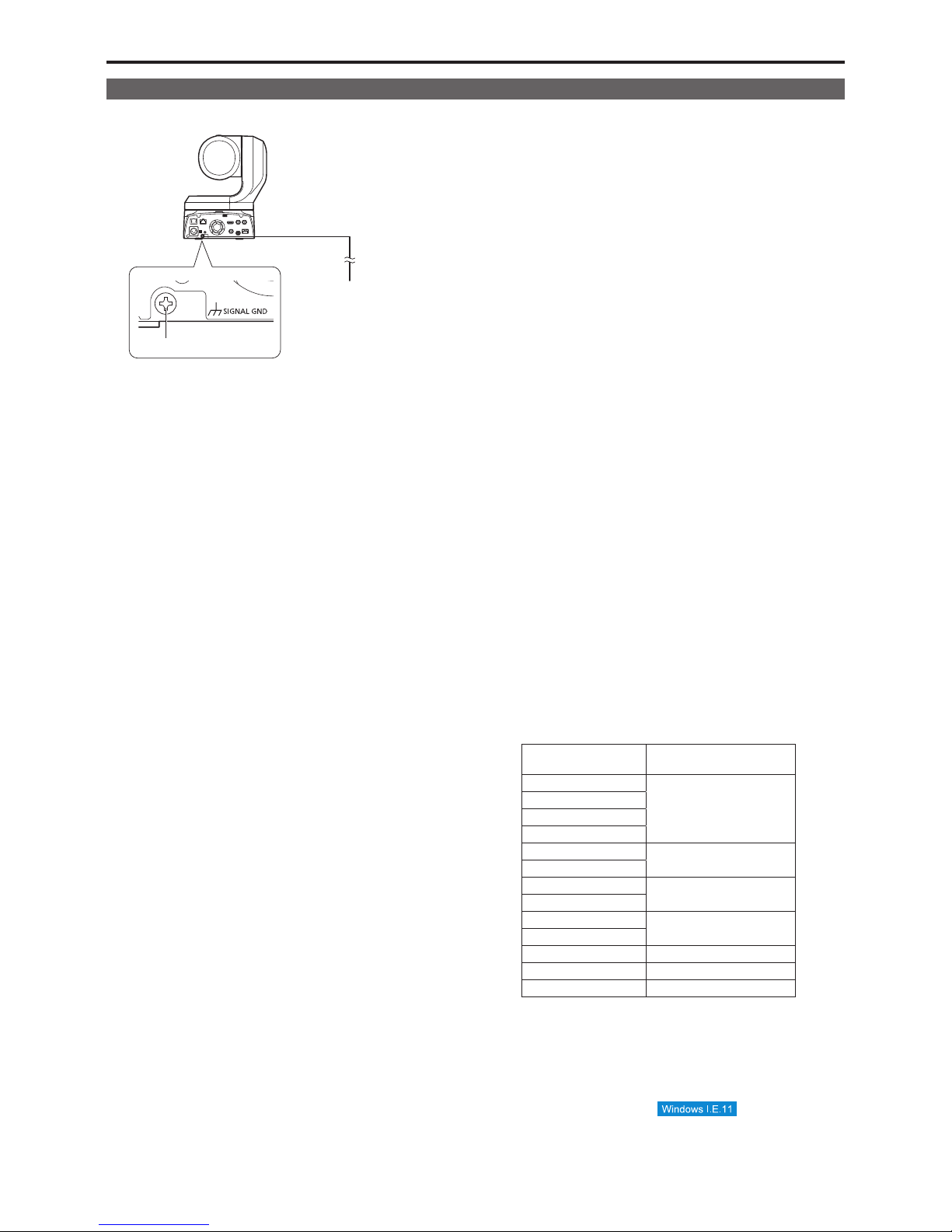
Note on grounding
• Ground the unit via the <SIGNAL GND> ground connector.
IR ID
AUDIO IN
Ground connector
to ground
connector on wall
outlet, ground
bar, etc.
Trademarks and registered trademarks
• Microsoft®, Windows®, Windows® 7, Windows® 10, Microsoft
Edge, Internet Explorer
®
, ActiveX® and DirectX® are either
registered trademarks or trademarks of Microsoft Corporation in
the United States and other countries.
• Apple, Mac, OS X, iPhone, iPod Touch, iPad, and Safari are
registered trademarks of Apple Inc., in the United States and other
countries.
• Android™ is a trademark of Google LLC.
• Intel
®
and Intel® Core™ are trademarks or registered trademarks
of Intel Corporation in the United States and other countries.
• Adobe
®
and Reader® are either registered trademarks or
trademarks of Adobe Systems Incorporated in the United States
and/or other countries.
• The terms HDMI and HDMI High-Definition Multimedia Interface,
and the HDMI Logo are trademarks or registered trademarks of
HDMI Licensing Administrator, Inc. in the United States and other
countries.
• Other names of companies and products contained in these
Operating Instructions may be trademarks or registered
trademarks of their respective owners.
About copyright and licence
Distributing, copying, disassembling, reverse compiling, reverse
engineering, and also exporting in violation of export laws of the
software provided with this unit are expressly prohibited.
Abbreviations
The following abbreviations are used in this manual.
• Microsoft
®
Windows® 7 Professional SP1 32/64-bit is abbreviated
to “Windows 7”.
• Windows
®
Internet Explorer® 11.0 32/64-bit is abbreviated to
“Internet Explorer”.
For the purposes of this manual, the model numbers of the units are
given as listed in the table below.
Model number of unit
Model number given in
manual
AW-UE150WP
AW‑UE150
AW-UE150KP
AW-UE150WE
AW-UE150KE
AW-HE130W
AW-HE130
AW-HE130K
AW-HS50N
AW‑HS50
AW-HS50E
AW-RP50N
AW‑RP50
AW-RP50E
AW-RP120G AW‑RP120
AW-RP150G AW‑RP150
AK-HRP200G AK‑HRP200
Illustrations and screen displays featured
in the manual
• What is shown in the manual’s illustrations and screen displays
may differ from how it is actually appears.
• Functions which can be used by Windows Internet Explorer 11
only are indicated using the
mark.
• The screenshots are used in accordance with the guidelines of
Microsoft Corporation.
7

Contents
Read this first! (For AW‑UE150WP, AW‑UE150KP) ............................ 2
Read this first! (For AW‑UE150WE, AW‑UE150KE) ............................ 4
Read this first! ...................................................................................... 7
Note on grounding ............................................................................... 7
Before use .............................................................................................. 9
Overview .............................................................................................. 9
Computer requirements ....................................................................... 9
Disclaimer of warranty ....................................................................... 10
Network security ................................................................................ 10
Features................................................................................................ 11
Controller supported ........................................................................... 12
Accessories ......................................................................................... 13
Optional accessories .......................................................................... 13
Operating precautions ........................................................................ 14
Wireless remote control (optional accessory).................................. 16
Parts and their functions .................................................................... 17
Camera unit ....................................................................................... 17
Wireless remote control (not supplied) .............................................. 24
Setting the remote control IDs ........................................................... 26
Network settings.................................................................................. 27
Use the Easy IP Setup Software to establish the unit’s settings........ 27
Installing the plug-in viewer software ................................................. 28
User authentication ............................................................................ 28
Basic shooting operations ................................................................. 29
How to turn the power on and off ...................................................... 29
Turning the power on ......................................................................... 29
Turning the power off ......................................................................... 29
Selecting the units ............................................................................... 30
Selecting the shooting modes (scene files)...................................... 31
Types of shooting modes ................................................................... 31
How to select the shooting mode ....................................................... 31
Shooting ............................................................................................... 32
What to do when encountering problems in the basic shooting
operations ........................................................................................ 33
More advanced operations ................................................................. 33
Manual shooting .................................................................................. 34
Manually adjusting the focus.............................................................. 34
Manually adjusting the iris.................................................................. 34
Manually adjusting the shutter speed ................................................ 34
Manually adjusting the gain ............................................................... 34
Preset memories.................................................................................. 35
White balance adjustment .................................................................. 36
Automatic adjustment (AWB: AWB A or AWB B) .............................. 36
Auto tracking white adjustment (ATW)............................................... 37
3200K and 5600K presets ................................................................. 37
VAR.................................................................................................... 37
Black balance adjustment .................................................................. 38
Automatic adjustment ........................................................................ 38
Black level (master pedestal) adjustment ......................................... 39
Genlock adjustment ............................................................................ 40
Horizontal phase adjustment ............................................................. 40
Basic setup operations ....................................................................... 41
When performing the operations using the wireless remote
control ............................................................................................ 41
Camera menu items ............................................................................ 42
Setting the camera menu items ......................................................... 42
Top Menu screen ............................................................................... 42
Camera screen .................................................................................. 43
Brightness 1/2 screen ........................................................................ 43
Brightness 2/2 screen ........................................................................ 44
Picture 1/8 screen .............................................................................. 45
Picture 2/8 screen .............................................................................. 46
Picture 3/8 screen .............................................................................. 47
Picture 4/8 screen .............................................................................. 47
Picture 5/8 screen .............................................................................. 48
Picture 6/8 screen .............................................................................. 49
Picture 7/8 screen .............................................................................. 50
Picture 8/8 screen .............................................................................. 50
Matrix 1/5 screen ............................................................................... 51
Matrix 2/5 screen ............................................................................... 51
Matrix 3/5 screen ............................................................................... 52
Matrix 4/5 screen ............................................................................... 52
Matrix 5/5 screen ............................................................................... 53
Lens screen ....................................................................................... 53
System screen ................................................................................... 54
Output 1/6 screen .............................................................................. 56
Output 2/6 screen .............................................................................. 57
Output 3/6 screen .............................................................................. 58
Output 4/6 screen .............................................................................. 58
Output 5/6 screen .............................................................................. 59
Output 6/6 screen .............................................................................. 59
Pan/Tilt screen ................................................................................... 60
Preset 1/2 screen ............................................................................... 61
Preset 2/2 screen ............................................................................... 62
Maintenance screen........................................................................... 62
Firmware Version 1/2 screen ............................................................. 63
Firmware Version 2/2 screen ............................................................. 63
IP Network screen.............................................................................. 64
Hour Meter screen ............................................................................. 65
Error Status screen ............................................................................ 65
Camera menu item table ..................................................................... 66
Displaying the web screen ................................................................. 72
Displaying the web screen using a personal computer...................... 72
Switching between the Live screen [Live] and Web setup screen
[Setup] ........................................................................................... 74
Web screen operations ....................................................................... 75
Live screen [Live] ............................................................................... 75
Web screen configurations ................................................................ 80
Logging into the Web screen ............................................................. 80
Web setup screen [SetUp] ................................................................. 81
Setting status screen [Setting Status] ................................................ 83
Basic screen [Basic]........................................................................... 84
Image/audio screen [Image/Audio] .................................................... 90
User management screen [User mng.] ............................................ 107
Network setup screen [Network] ...................................................... 110
Maintenance screen [Maintenance] ................................................. 122
Displaying the web screen using a mobile terminal ...................... 125
System log displays .......................................................................... 129
Limiters............................................................................................... 131
Setting/releasing the limiters ........................................................... 132
Basic limiter operations .................................................................... 132
Setting the limiters ........................................................................... 132
Releasing the limiters....................................................................... 132
Resetting the limiters ....................................................................... 132
Safe mode .......................................................................................... 133
Concerning the safe mode ............................................................... 133
Detection of equipment trouble ........................................................ 133
Troubleshooting ................................................................................ 134
Specifications .................................................................................... 143
Index ................................................................................................... 145
8

Before use
Overview
• This product is an all-in-one pan-tilt head remote camera, compatible
with 4K/60p format, and the first in its field to support 4K/12G-SDI.
• Equipped with an optical 20x zoom lens and 4K-compatible MOS
sensor, it is possible to record high-quality images with a high degree
of realism with the horizontal resolution of 1600 lines.
With its high sensitivity and built-in image-shake correction and nightmode functions, the unit can record in a wide range of environments.
• This product is compatible with NDI|HX technology of NewTek, Inc.
• The unit supports transmission of video to NewTek NDI compatible
software applications and hardware devices over a network.
• When a controller is connected, camera operations can be performed
smoothly via IP control or serial control.
• The unit features a night mode that exposes subjects to infrared rays,
making it possible to shoot even under low-light conditions.
• When the unit is connected to a personal computer via an IP network,
it can be operated via a web browser.
• With a variety of 4K interfaces, there are individual outputs for HD and
SDI, so the unit can be used flexibly in a wide range of situations as a
4K-compatible remote camera.
• Connection with a Panasonic camera controller is also possible via
Panasonic's proprietary serial communication format.
• The unit is available in white (AW-UE150WP/AW-UE150WE) or black
(AW-UE150KP/AW-UE150KE) to suit your intended application and
environment.
Computer requirements
CPU Intel
®
Core™ 2 DUO 2.4 GHz or more
recommended
Memory For Windows:
1 GB or more
For Mac:
2 GB or more
Network function 100/1000BASE-T or -TX,
RJ-45 connector
Image display Resolution: 1920 × 1080 pixels or more
Color generation: True Color 24-bit or more
Supported operating
systems and
web browsers
For Windows:
Microsoft
®
Windows® 7, 10
Windows
®
Internet Explorer® 11.0
64-bit/32-bit
Microsoft Edge
Chrome
For Mac:
OS X 10.13
Safari 11
OS X 10.12
Safari 10
OS X 10.11
Safari 9
OS X 10.10
Safari 8
Chrome
For iPhone, iPad, iPod touch:
iOS
Standard web browsers
For Android:
Android OS
Standard web browsers
Other Adobe
®
Reader®
(for viewing the operating instructions available on
the website)
9

IMPORTANT
• Failure to provide the required personal computer
environment may slow down the delineation of the images on
the screen, make it impossible for the web browser to work
and cause other kinds of problems.
<NOTE>
• Depending on the software version of the unit, an update may be
necessary.
• Use the desktop version of Internet Explorer. (Internet Explorer for
Windows UI is not supported.)
• For the latest information on compatible operating systems and web
browsers, visit the support desk at the following website.
https://pro-av.panasonic.net/
Disclaimer of warranty
IN NO EVENT SHALL Panasonic Corporation BE LIABLE TO ANY
PARTY OR ANY PERSON, EXCEPT FOR REPLACEMENT OR
REASONABLE MAINTENANCE OF THE PRODUCT, FOR THE
CASES, INCLUDING BUT NOT LIMITED TO BELOW:
A ANY DAMAGE AND LOSS, INCLUDING WITHOUT LIMITATION,
DIRECT OR INDIRECT, SPECIAL, CONSEQUENTIAL OR
EXEMPLARY, ARISING OUT OF OR RELATING TO THE
PRODUCT;
B PERSONAL INJURY OR ANY DAMAGE CAUSED BY
INAPPROPRIATE USE OR NEGLIGENT OPERATION OF THE
USER;
C UNAUTHORIZED DISASSEMBLE, REPAIR OR MODIFICATION
OF THE PRODUCT BY THE USER;
D INCONVENIENCE OR ANY LOSS ARISING WHEN IMAGES
ARE NOT DISPLAYED, DUE TO ANY REASON OR CAUSE
INCLUDING ANY FAILURE OR PROBLEM OF THE PRODUCT;
E ANY PROBLEM, CONSEQUENTIAL INCONVENIENCE,
OR LOSS OR DAMAGE, ARISING OUT OF THE SYSTEM
COMBINED BY THE DEVICES OF THIRD PARTY;
F ANY DEMANDS FOR COMPENSATION, CLAIMS, ETC.
OCCASIONED BY THE INFRINGEMENT OF PRIVACY BY
INDIVIDUALS OR ORGANIZATIONS WHOSE IMAGES WERE
SHOT BY THE USER BECAUSE THESE IMAGES (INCLUDING
THE RECORDINGS MADE) WERE MADE AVAILABLE BY THE
USER BECAUSE IN THE PUBLIC DOMAIN FOR SOME REASON
OR OTHER OR BECAUSE THE IMAGES ENDED UP BEING
USED FOR PURPOSES OTHER THAN THE ONE DESCRIBED
ABOVE;
G LOSS OF REGISTERED DATA CAUSED BY ANY FAILURE.
Network security
As the unit intended to be used while connected to a network, the
following security risks exist.
A Leakage or theft of information through the unit
B Unauthorized operation of the unit by persons with malicious intent
C Interference with or stoppage of the unit by persons with malicious
intent
It is your responsibility to take precautions, such as those described
below, to protect yourself against the above network security risks.
• Use the unit in a network secured by a firewall, etc.
• If the unit is connected to a network that includes personal computers,
make sure that the system is not infected by computer viruses or other
malicious programs (using a regularly updated antivirus program, antispyware program, etc.).
• Protect your network against unauthorized access by restricting users
to those who log in with an authorized user name and password.
• After accessing the unit as an administrator, be sure to close all web
browsers.
• Change the administrator password periodically.
• Restrict access to the unit by authenticating the users, for example,
to prevent setting information stored on the unit from leaking over the
network.
• Do not install the unit in locations where the unit, cables, and other
parts can be easily damaged or destroyed by persons with malicious
intent.
• Avoid connections that use public lines.
<NOTE>
Notes on user authentication
• User authentication on the unit can performed via digest authentication
or basic authentication. If basic authentication is used without the use
of a dedicated authentication device, password leaks may occur.
We recommend using digest authentication or host authentication.
Usage restrictions
• We recommend connecting the unit, controller, and any computers to
the same network segment.
Events based on settings inherent to the network devices, for example,
may occur in connections that include different segments, so be sure
to perform checks prior to operation.
10
Before use (continued)

Multi‑format support
• You can switch between the following formats via the camera
menus or a web browser.
[4K format]
2160/59.94p, 2160/50p, 2160/29.97p
*
1
, 2160/25p
*
1
, 2160/24p
*
1
,
2160/23.98p
*
1
[HD format]
1080/59.94p, 1080/50p, 1080/29.97p
*
1
, 1080/29.97PsF,
1080/25p
*
1
, 1080/25PsF, 1080/23.98p
*
2
, 1080/24p
*
1
,
1080/23.98p
*
1
, 1080/23.98PsF, 1080/59.94i, 1080/50i,
720/59.94p, 720/50p
*1
Native output
*2
OVER 59.94i output (your monitor may recognize the signal as
59.94i).
*3
OVER 50i output (your monitor may recognize the signal as 50i).
1‑type 4K MOS sensor and high‑performance
20x zoom lens featured
• A newly developed 1-type 4K MOS sensor and DSP (digital signal
processor) are incorporated. High-quality pictures are obtained by
video processing in many different kinds of ways.
• In addition to its optical 20x zoom lens, the unit comes with a 10x
digital zoom to achieve high-quality images that overflow with
ambiance.
• A dynamic range stretcher (DRS) function that compensates for
overexposure and loss of dark detail and a digital noise reduction
(DNR) function for minimizing image lag even in dark locations
and shooting scenes clearly are incorporated to reproduce clean
and clear images in a wide range of applications.
Easy operation of unit enabled by its
integration with a high‑performance pan‑tilt
head unit
• Operations at the high speed of 60°/s
• Wide rotational angles with a panning range of ±175° and a tilting
range from –30° to 210°
• Quiet operation with noise levels of NC35
• Storage of up to 100 positions in the preset memory
(The number of preset memories that can be used varies from one
controller to another.)
Built‑in night mode
• The unit supports infrared shooting.
By exposing subjects to infrared rays, shooting under ordinarily
difficult low-light conditions is possible.
(Image output will be in black and white.)
• The iris will be fixed at open.
IP image output functions
• The unit is equipped with image compression and IP transmission
LSI capabilities. Output in 4K quality at up to 60 fps.
• Operation with IP control allows for a wide range of applications,
such as controlling the camera from remote locations.
High degree of compatibility with Panasonic’s
currently available controllers, enabling a
flexible system to be put together
• A maximum of five units can be operated by serial control from
one of Panasonic’s currently available controllers (AW-RP150).
The unit can also be used together with the cameras and pan-tilt
head unit systems currently available from Panasonic Corporation
so that an existing system can be used to advantage to put
together a system that is even more flexible.
<NOTE>
• It may be necessary to upgrade the version of the controllers
other than AW-RP150 in order to support the unit. For details on
upgrading, visit the support page on the following website.
https://pro-av.panasonic.net/
The maximum distances between the units and controller is
1000 meters (3280 ft). (when serial control is exercised)
Use of an external device or some other means must be
provided separately in order to extend the video signal
connections.
Easy construction of systems thanks to
integrated design used for pan‑tilt head,
camera and lens
• By integrating the camera, lens and pan-tilt head into a single unit,
it is now easier to construct systems.
Use of easy‑to‑operate wireless remote control
(optional accessory) is possible
• A wireless remote control capable of operating up to four units can
be used.
It can easily be used to set the various functions or switch
between them while viewing the menu screens.
Flexible camera layout enabled by simple
connection and installation
• This unit features excellent connectivity and installability thanks
to the IP control; a lightweight main unit, and the turn-lock
mechanism, which enables the user to install it on his or her own
(only when used indoors).
<NOTE>
• Bear in mind that this unit is designed to be used indoors only:
It cannot be used outdoors.
While including a larger 4K lens and pan/
tilt mechanism, the unit still has the same
installation footprint as previous models.
• The unit maintains the compact installation footprint of previous
models.
Easy connections and settings courtesy of IP
control
• Up to a hundred units can be operated by IP connection from a
Panasonic controller (AW-RP150).
(The maximum length of the LAN cables is 100 meters (328 ft).)
PoE++
*
4
eliminates need for camera power
configurations
• Configurations for camera's power supply are not necessary when
the unit is connected to a network device that supports the PoE++
standard (IEEE802.3bt compliant)
*
5
.
<NOTE>
• The unit does not support software authentication (LLDP
communication).
• If the external DC power supply and a PoE++ power supply are
connected simultaneously, the external DC power supply will have
priority. If the external DC power supply is disconnected while both
power supplies are connected, the unit will restart automatically,
and the image will be interrupted.
• Use a Category 5e cable or higher when using a PoE++ power
supply. The maximum length of the cable between the power
supply unit and the unit is 100 meters (328 ft). Using a cable that
is lower than Category 5e may result in reduced power supply
capabilities.
• When a PoE++ injector is connected to a personal computer that
supports Gigabit Ethernet using a straight LAN cable, the personal
computer may not recognize the injector in rare cases. In such
cases, connect the personal computer to the unit using a LAN
cable (or via cross connection).
*4
Power over Ethernet Plus Plus. Referred to as "PoE++" in this
manual.
*5
For details on PoE++ power supply devices for which operation
has been verified, consult your local dealer.
Features
11

z AW‑RP150
<NOTE>
• The following operations can not be performed via the following controllers.
• It may be necessary to upgrade the version of the controller in order to support the unit.
For details on upgrading, visit the support page on the following website.
https://pro‑av.panasonic.net/
Item AW‑RP120 AW‑RP50 AW‑HRP200
Camera OSD menu operation
Scene
Iris Mode
Shutter Mode
Gain
ND Filter
Day/Night
White Balance Mode
AWB/ABB
Color Temperature
R Gain/B Gain
Pedestal
R Pedestal/B Pedestal
Detail
V Detail Level
CAM/BAR
Pan
Tilt
Preset
Preset Speed
Preset Speed Table
Preset Scope
Freeze During Preset
Focus Mode
Zoom
Digital Extender
OIS
Tally
*1
If the setting value is changed on another device, it may take some time for the setting value to be applied.
*2
If the Shutter Mode is not turned off/on after configuration, the value will not be changed.
*3
Improper operation will occur when Gain is set to 19 dB or higher.
*4
If the setting value is changed on another device, the setting value will not be applied.
(If the value is configured locally on the device, the value will be applied.)
*5
The value range display will be incorrect (–150 to +150).
Controller supported
12
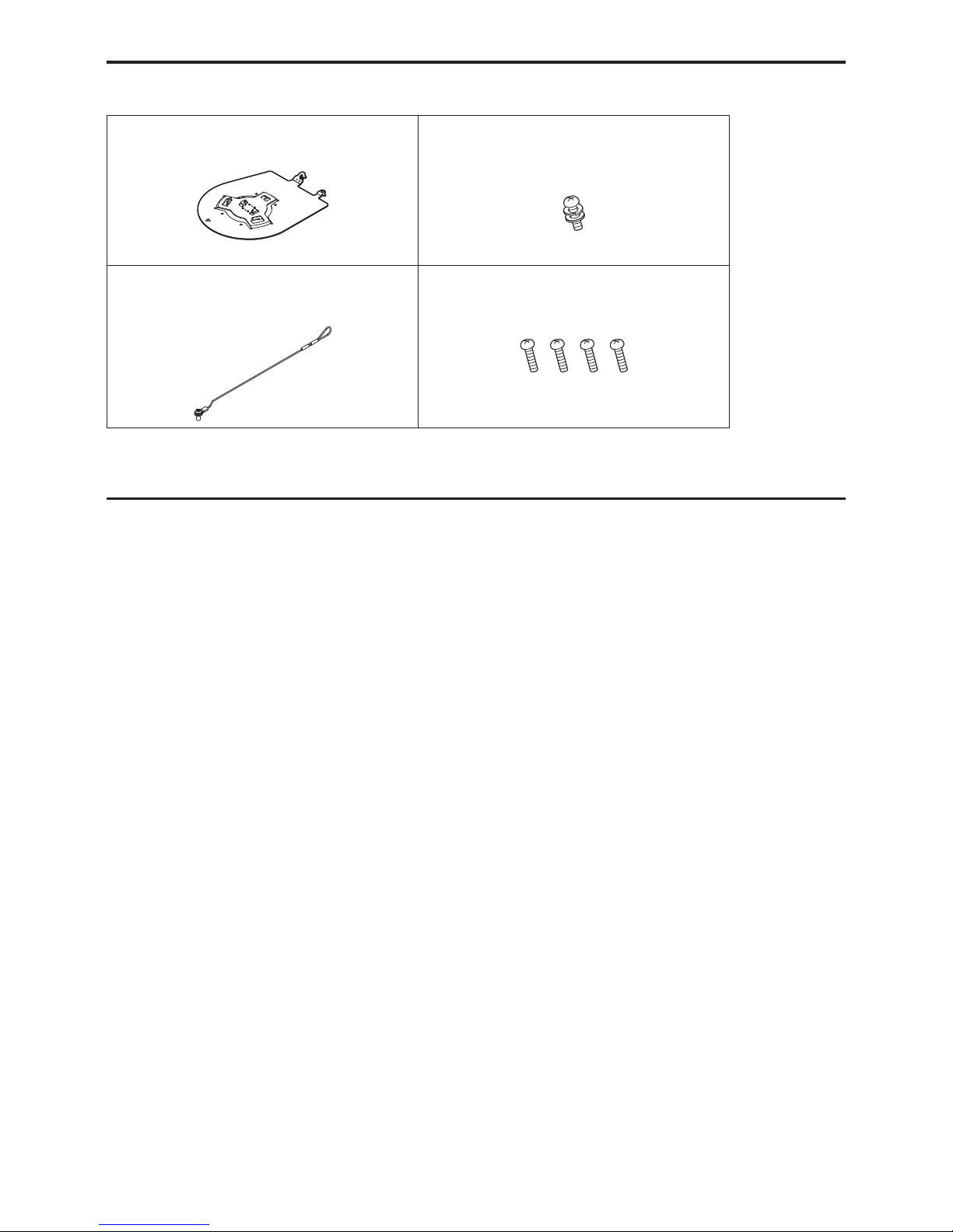
Accessories
Check that the following accessories are present and accounted for.
• After removing the product from its container, dispose of the power cable cap (if supplied) and packing materials in an appropriate manner.
Mount bracket for installation surface
(Hanging/Desktop) (1)
Main unit mounting screw (with flat washer, spring
washer)
M3×6 mm (1)
Drop‑prevention wire (1)
Drop‑prevention wire mounting screw
(1)
(comes attached to the unit)
Bracket mounting screws (bind‑head)
M4×10 mm (4)
Optional accessories
z Wireless remote controller AW‑RM50G (Size “AA” dry battery x 2, obtained separately)
z Direct ceiling mount bracket WV‑Q105A
z Fiber module
13

Shoot under the proper lighting conditions.
To produce pictures with eye-pleasing colors, shoot under the
proper lighting conditions.
The pictures may not appear with their proper colors when shooting
under fluorescent lights. Select the proper lighting as required.
To ensure a stable performance in the long
term
Using the unit for prolonged periods in locations where the
temperature and humidity levels are high will cause its parts to
deteriorate, resulting in a reduction of its service life.
(Recommended temperature: Max. 35 °C (95 °F))
Ensure that a cooling unit or heating unit will not blow any air
directly toward the installation location.
Do not point the camera at
strong lights.
When parts of the MOS sensor are
exposed to spotlights or other strong
lights, blooming (a phenomenon where
the edges of strong lights become
blurred) may occur.
Bright subject
Blooming
What happens with high‑brightness subjects
Flare may occur if an extremely bright light source is pointed at
the lens. In a case like this, change the angle or take some other
remedial action.
When using the automatic functions
• In the [Scene] such as the camera menu, the initial settings on
some items has been set to auto, making it impossible for these
items to be operated manually. To operate them manually, switch
from the auto settings to the manual settings as required.
• When using the ATW (auto tracking white adjustment) function
under fluorescent lights, the white balance may vary.
• In some situations, it may be hard to focus at the auto setting. In
cases like this, select the manual setting, and focus manually.
Zooming and focusing
When the focus is set manually, out-of-focusing may occur during
zooming.
After zooming, if necessary, either adjust the focus or set the focus
to auto.
When using the focus at the manual setting, proceed with zooming
after setting the focus position at the Tele end where the focusing
accuracy is higher. (However, if the distance from the unit to the
subject is less than 1.5 meters (4.92 ft), the subject may shift out of
focus at the Wide end.)
If zooming is performed to the Tele end after having adjusted the
focus at the Wide end, out-of-focusing may occur.
Operation of the lens when the power is turned
on
When the unit’s power is turned on, the zoom, focus and iris are
adjusted automatically.
The unit comes with the safe mode.
The safe mode is function designed to protect the unit from damage.
For further details, refer to “Concerning the safe mode” (→ PDF
page 133).
Operating temperature range
Avoid using the unit in cold locations where the temperature drops
below 0 °C (32 °F) or hot locations where the temperature rises
above 40 °C (104 °F) since these temperatures downgrade the
picture quality and adversely affect the internal parts.
Concerning the MONI OUT signal
It is anticipated that MONI OUT is used in applications such as for
outputting images to be cropped from 4K to HD and for monitoring
images.
Concerning the HDMI interface standard
This unit has been certified as HDMI-compatible, but on rare
occasions images may not be displayed depending on the HDMI
device which has been connected to the unit.
Color bars
• Color bars are used to adjust the color phase, and the widths and
positions of these bars may differ from other models.
• The setting for the “Down CONV. Mode” item when color bars are
displayed is fixed at “Squeeze”.
H.264/H.265 patent pool licensing
This product is licensed based on the AVC Patent Portfolio License,
and the license does not extend beyond uses by users, who engage
in the acts described below, for their own personal and non-profit
applications.
(i) Recording of image information in compliance with the AVC
standard (hereafter, “AVC videos”)
(ii) Playing of AVC videos recorded by consumers engaging
in personal activities or AVC videos acquired from licensed
providers
For details, visit MPEG LA, LLC website (http://www.mpegla.com).
Concerning PoE++ power supply
The unit complies with the IEEE802.3bt standard. Use a compatible
Ethernet hub and PoE++ injector to use a PoE++ power supply.
For details on Ethernet hubs and PoE++ injectors for which
operations have been verified, consult your local dealer.
• The unit does not support software authentication (LLDP
communication).
Turn off the power before connecting or
disconnecting the cables.
This unit is not equipped with a power switch.
Turn off the DC 12 V power supply or PoE++ power supply device
before connecting or disconnecting cables.
Handle the unit carefully.
Do not drop the unit or subject it to strong impact or vibration.
Failure to obey may cause the unit to malfunction.
When the unit is not in use
Turn off the unit’s power when it is not in use.
When the unit is no longer going to be used, do not leave it lying
around, but be absolutely sure to dispose of it properly.
Do not touch the optical system parts.
The optical system parts are vital to the operation of the camera.
Under no circumstances must they be touched.
In the unlikely event that they have become dusty, remove the
dust by using a camera blower or by wiping them gently with a lens
cleaning paper.
Do not point the camera directly at the sun or a
laser beam no matter whether it is turned on or
not.
Taking images of the sun, laser beams, or other brightly lit subjects
for prolonged periods of time may damage the CCD.
Operating precautions
14

Personal computer used
If the same image is displayed for a prolonged period on a Personal
computer's monitor, the monitor may be damaged. Use of a screen
saver is recommended.
Concerning the IP address setting
Do not run the Easy IP Setup Software on a multiple number of
personal computers for a single camera and set the IP address at
the same time.
Otherwise, you will be unable to complete the proper procedure and
set the IP address correctly.
Do not allow foreign matter to make contact
with the rotating parts.
Failure to obey may cause the unit to malfunction.
Do not get close to the moving parts of the
camera head.
Do not put your fingers or body close to the unit while it is in
operation. Doing so may result in injury or cause the unit to
malfunction.
Furthermore, if the unit hits a person or obstacle, during the panning
or tilting operation, the unit will enter into the safe mode.
For further details, refer to the PDF page 133.
Keep the unit away from water.
Avoid all direct contact with water. Failure to obey may cause the
unit to malfunction.
Maintenance
Turn off the unit’s power before proceeding with maintenance.
Failure to obey may result in injuries.
Wipe the surfaces using a soft dry cloth. Avoid all contact with
benzine, paint thinners and other volatile substances, and avoid
using these substances. Otherwise, the casing may become
discolored.
Do not turn the camera head by hand.
Turning the camera head by hand may cause the unit to
malfunction.
Use the unit in an environment with minimal
moisture and dust.
Avoid using the unit in an environment with high concentration of
moisture or dust since these conditions will damage the internal
parts.
About the lens/pan‑tilt head
If the lens, pan-tilt head, and other parts are not operated for a long
period of time, the viscosity of the grease applied inside them may
increase and operation may become no longer possible. Move the
lens and pan/tilt head regularly.
About consumables
The following parts are consumables. Replace them using the
lifespans as a guide.
The lifespans may vary depending on the operating environment
and operating conditions.
The lifespans are a guide for when the unit is used at 35 °C (95 °F).
• Cooling fan: Approx. 15000 hours
Contact your dealer regarding replacements.
Disposal of the unit
When the unit has reached the end of its service life and is to be
disposed of, ask a qualified contractor to dispose of the unit properly
in order to protect the environment.
Information on software used with this product
This product includes GNU General Public License (GPL) and GNU Lesser General Public License (LGPL) licensed software, and the customer is
entitled to obtain, modify, or redistribute the source code for the software.
This product includes MIT Licensed software.
This product includes BSD Licensed software.
For details on obtaining the source codes, visit the following website.
https://panasonic.net/cns/oss/index.html
However, do not contact Panasonic for questions regarding obtained source codes.
15
Operating precautions (continued)
This unit can be operated by remote control using a wireless
remote control (model number: AW‑RM50G) purchased separately.
Check out the following points before using the wireless remote
control.
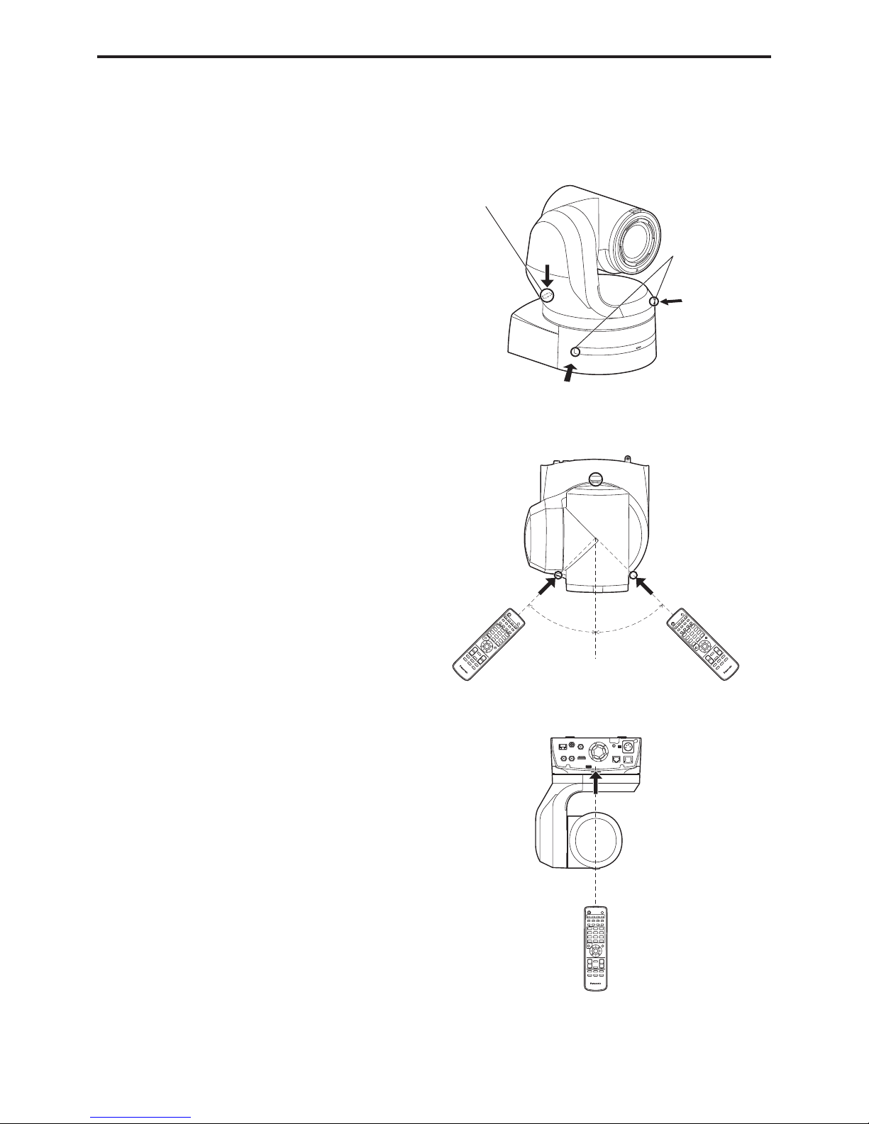
z Point the wireless remote control at the unit’s wireless
remote control signal light‑sensing area (front panel or
back panel), and operate it within a range of 10 meters
(32.8 ft) from these areas.
z Refer to <Layout of wireless remote control signal
light‑sensing areas> on the right.
z The signal sensing distance is reduced if the angle at
which the wireless remote control signals are sensed is
increased.
The light-sensing sensitivity is reduced to about one-half when the
wireless remote control is pointed at an angle of 40 degrees from
each position in front of a wireless remote control signal light-sensing
area (front panel or back panel).
If the remote control is operated from the behind the unit, it may be
either difficult or impossible to perform the desired operations.
z If the unit is installed near fluorescent lights, plasma
monitors or other such products or if the unit is
exposed to sunlight, the effects of the light may make it
impossible for the unit to be operated using the wireless
remote control.
Be sure to follow the steps below for installation and use.
• Take steps to ensure that the wireless remote control signal lightsensing area will not be exposed to the light from fluorescent lights,
plasma monitors or other such products or from the sun.
• Install the unit away from fluorescent lights, plasma monitors and
other such products.
z For about 10 minutes even after the batteries have been
removed from the wireless remote control, the selection
of the operation to be performed (the <CAM1>, <CAM2>,
<CAM3> or <CAM4> button which was pressed last) will
remain stored in the memory.
When a longer period of time elapses, however, the
selection is reset to the status established when the
<CAM1> button was pressed.
<Layout of wireless remote control signal light-sensing areas>
<NOTE>
• The arrows in the figure below show the light-sensing directions in
which the wireless remote control signals travel.
Wireless remote
control signal light‑
sensing area (back
panel, 1 place)
Wireless remote
control signal light‑
sensing area (front
panel, 2 places)
• Top view
• Rear panel view
Approx. 45° Approx. 45°
Wireless remote control (optional accessory)
16
12 V IN
IR ID
AUDIO IN
RS-422
SERVICE
MONI OUT
12G SDI OUT
3G SDI OUT G/L IN
LAN
LINK ACT
SFP+
14G FIBER
1
2
3
4
5
6
7
5
8
6
23
9 10 11 12
14
21 22201918
17
1615
13
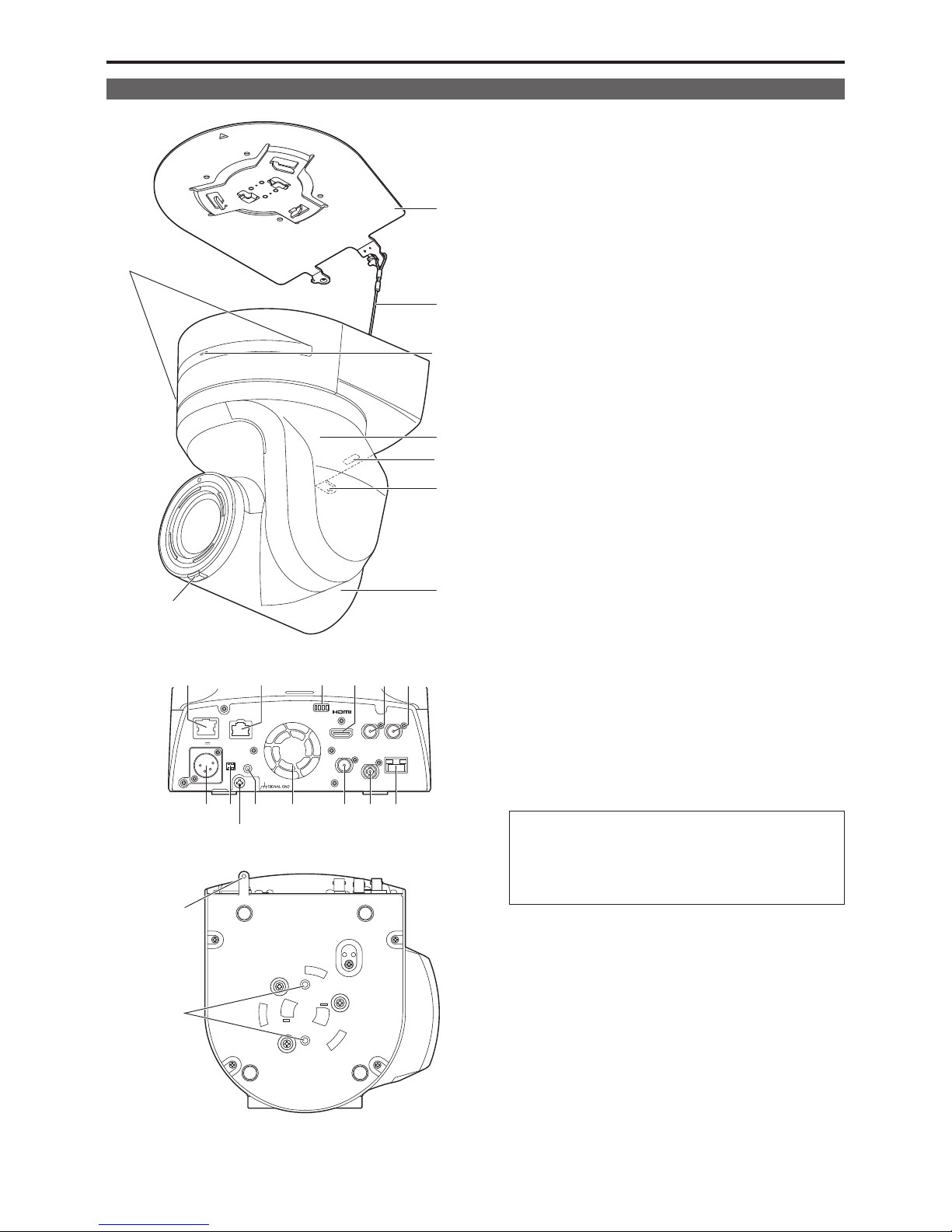
Rear panel
Bottom panel
1. Mount bracket for installation surface (supplied
accessory)
Mount this bracket onto the installation surface, and then attach the
camera main unit to the bracket.
2. Drop‑prevention wire
This wire is screwed down to the bottom panel of the camera main
unit. Loop the circle part of the wire around the hook of the mount
bracket.
3. Status display lamp
This lights in the following way depending on the status of the unit.
Orange: When the standby status is established
Green: When the power is on
Red: When trouble has occurred in the unit
Green and blinks twice:
When a signal matched by the remote control ID has
been received from the wireless remote control (optional
accessory) while the power is on
Orange and blinks twice:
When a signal not matched by the remote control ID has
been received from the wireless remote control (optional
accessory) while the power is on
Red and blinking:
Firmware being updated
4. Tilt head
This rotates in the right and left direction.
5. Wireless remote control signal light‑sensing area
The light-sensing area is provided in three places, on the front panel
of the camera pedestal and at the top of the rear panel.
6. Hole for securing the camera pedestal
This hole is provided in the bottom panel of the camera pedestal.
7. Camera head
This rotates in the up and down direction.
8. Tally lamp
This comes on or goes off in response to the control from the
controller but only when “On” has been selected as the tally lamp use
setting. The tally lamp is red or green.
9. LAN connector for IP control <LAN LINK/ACT>
This LAN connector (RJ-45) is connected when exercising IP control
over the unit from an external device. Use a cable with the following
specifications for the connection to this connector.
When using a PoE++ Ethernet hub
LAN cable (category 5e or above, straight cable or cross cable),
max. 100 m (328 ft)
When not using a PoE++ Ethernet hub
LAN cable (category 5 or above, straight cable),
max. 100 m (328 ft)
Parts and their functions
Camera unit
17
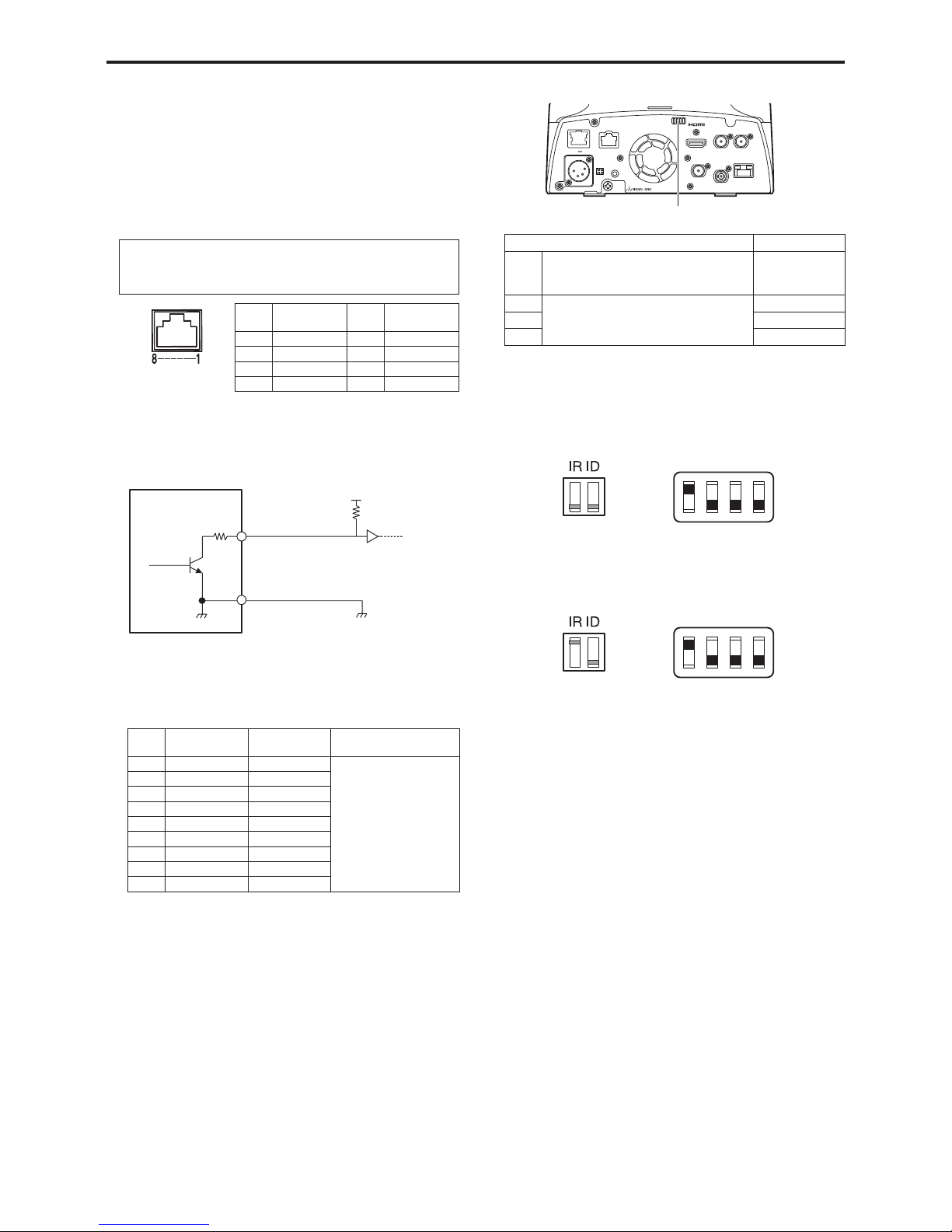
10. RS‑422 connector <RS‑422>
This RS-422 connector (RJ-45) is connected when exercising serial
control over the unit from an external device. Use a cable with the
following specifications for the connection to this connector.
The red tally lamp can be lit by shorting the R-TALLY signal (pin 2)
with GND (pin 1).
<NOTE>
• Do not apply a voltage to the TALLY signal pin.
• Menu settings enable the output to pin 7 and pin 8 of the red tally
and green tally signals received by the unit. Output is by contact
output, and normally is “OPEN”, then it becomes “MAKE” for output.
LAN cable
*
1
(category 5 or above, straight cable),
max. 1000 m (3280 ft)
*1
Use of an STP (shielded twisted pair) cable is recommended.
Pin
No.
Signal
Pin
No.
Signal
1 GND 5 TXD+
2 R_TALLY_IN 6 RXD+
3 RXD– 7
OPTION_OUT1
4 TXD– 8
OPTION_OUT2
Example R_TALLY_OUT, G_TALLY_OUT connector
connections
AW-UE150
R_TALLY_OUT
G_TALLY_OUT
GND
1 kΩ
(Maximum current
5 mA)
(Maximum voltage 12 V)
Voltage resistance: Maximum DC12 V
Current: Maximum 100 mA
• [TRUNK] connector
JEY-9S-1A3F(LF)(SN) (manufactured by Japan Solderless
Terminal Mfg. Co., Ltd.)
Pin
No.
Function Signal flow Remarks
1 TRUNK1_TX (C) CAM → CCU RS-422/RS-232C
• Selection by menu
• Connect to the (C)
side with RS-232C
connection. (H) side is
open.
2 TRUNK1_TX (H) CAM → CCU
3 TRUNK1_RX (H) CCU → CAM
4 TRUNK1_RX (C) CCU → CAM
5 GND
6 TRUNK2_TX (C) CAM → CCU
7 TRUNK2_TX (H) CAM → CCU
8 TRUNK2_RX (H) CCU → CAM
9 TRUNK2_RX (C) CCU → CAM
11. Service switches <SERVICE>
12 V IN
IR ID
AUDIO IN
RS-422
SERVICE
MONI OUT
12G SDI OUT
3G SDI OUT G/L IN
LAN
LINK ACT
SFP+
14G FIBER
Service switches
Function Factory settings
SW1 Switches for initialization
(Refer to the explanations in “Initialization 1”
and “Initialization 2”)
OFF
SW2
Always leave at OFF (used for factory
adjustments)
OFF
SW3 OFF
SW4 OFF
<NOTE>
• Perform switch settings before turning the unit on.
Initialization 1
• Resets the user ID/password for network connections.
• With the IR ID switches and service switches set as shown below,
turn on the power of the unit.
SW1
ON
OFF
SW2 SW3 SW4
Initialization 2
• The unit is reset to the state it was in at the time of purchase. (All
camera menu setting values and network setting values are reset.)
• With the IR ID switches and service switches set as shown below,
turn on the power of the unit.
SW1
ON
OFF
SW2 SW3 SW4
12. HDMI connector <HDMI>
This is the HDMI video output connector.
13. 3G SDI OUT connector <3G SDI OUT>
This is the 3G SDI video signal output connector.
18
Parts and their functions (continued)
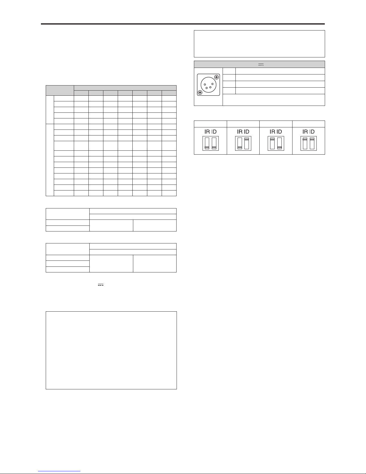
14. G/L IN connector <G/L IN>
This is the external sync signal input connector.
This unit supports BBS (Black Burst Sync) and tri-level
synchronization.
Supply to this connector the signals that correspond to the video
signal format which has been set.
• G/L support format
Frequency: 59.94 Hz, 29.97 Hz, 50 Hz, 25 Hz
: supported : not supported
System format
REF‑IN
1080/59i 1080/50i
1080/23PsF
525/59i 625/50i 720/59p 720/50p
UHD
2160/59.94p
2160/29.97p
2160/23.98p
2160/50p
2160/25p
HD
1080/59.94p
1080/59.94i
1080/29.97PsF
1080/23.98p
over 59.94i
480/59.94i
1080/23.98PsF
720/59.94p
1080/50p
1080/50i
1080/25PsF
576/50i
720/50p
Frequency: 24 Hz
Format
External sync signal input format
Tri‑level sync
2160/24p 1080/24p
1080/24PsF
―
1080/24p
Frequency: 23.98 Hz
Format
External sync signal input format
Tri‑level sync
2160/23.98p 1080/23.98p
1080/23.98PsF
―
1080/23.98p
1080/23.98PsF
15. DC IN connector <12V IN> (XLR connector)
Input 10.8 V (12 V–10%) DC.
<NOTE>
• Use a DC cable with the following lengths.
For 12 V input: Max. 3 m (9.84 ft) (when using an AWG16 cable)
External DC power supply
Connect after making sure that the output voltage of the external DC
power supply is compatible with the rated voltage of the camera.
Select an output amperage for the external DC power supply with a
margin above the total amperage of the connected devices.
The total amperage of connected devices can be calculated with the
following formula.
Total power consumption ÷ voltage
When the power of the camera is turned on, inrush current is generated.
Insufficient power supply when turning on the power may cause a
malfunction. We recommend that you use an external DC power supply
that can assure double the capacity of the total power consumption of the
camera and connected devices that are turned on by interlock when the
power of the camera is turned on (such as lenses, wireless microphone
receivers).
• Make sure of the pin alignment of the DC output terminal of the
external DC power supply and the camera DC IN connector, and
connect the polarity correctly.
If the +12 V power supply is mistakenly connected to the GND terminal,
it may cause fire or malfunction.
12V IN
1
2
3
4
1 GND
2 —
3 —
4 +12V
HA16RA-4P (77)
Hirose Electric Co.
16. IR ID switches <IR ID>
CAM1 CAM2 CAM3 CAM4
These are used to select the ID of the wireless remote control
(optional accessory).
The IR ID switch settings “CAM1” to “CAM4” correspond to the
<CAM1> to <CAM4> buttons on the wireless remote control.
17. Ground connector
Connects to the ground connector on a wall outlet, ground bar, etc.
for grounding. (→ page 7)
18. AUDIO IN connector <AUDIO IN>
Inputs external audio (microphone, line).
19. Ventilation holes
20. MONITOR OUT connector <MONI OUT>
This is an SDI video signal output connector. Use it in applications
such as for images being cropped from 4K to HD and for monitoring
images.
21.
12G SDI OUT connector <12G SDI OUT>
This is a 12G-SDI video signal output connector.
22.
SFP+ Fiber connector <SFP+ 14G FIBER>
This is an optical fiber video signal output connector.
23. Tripod screw holes
(Screw: 1/4-20 UNC, ISO 1222 (6.35 mm))
Use these screw holes when securing the unit to a tripod, etc.
19
Parts and their functions (continued)

Output conditions for each video format
Frequency System Format HDMI 12G SDI OUT SFP+ 14G FIBER 3G SDI OUT MONI OUT
59.94Hz
2160/59.94p 2160/59.94p 2160/59.94p 2160/59.94p
1080/59.94p
1080/59.94i
1080/59.94i
2160/29.97p 2160/29.97p 2160/29.97p 2160/29.97p
1080/29.97p
1080/29.97PsF
1080/29.97p
1080/29.97PsF
1080/59.94p 1080/59.94p 1080/59.94p 1080/59.94p
1080/59.94p
1080/59.94i
1080/59.94i
1080/59.94i 1080/59.94p 1080/59.94i 1080/59.94i 1080/59.94i 1080/59.94i
1080/29.97p 1080/29.97p 1080/29.97p 1080/29.97p 1080/29.97p 1080/29.97p
1080/29.97PsF 1080/29.97p 1080/29.97PsF 1080/29.97PsF 1080/29.97PsF 1080/29.97PsF
1080/23.98p over
59.94i
1080/23.98p
1080/23.98p over
59.94i
1080/23.98p over
59.94i
1080/23.98p over
59.94i
1080/23.98p over
59.94i
720/59.94p 720/59.94p 720/59.94p 720/59.94p 720/59.94p 720/59.94p
50Hz
2160/50p 2160/50p 2160/50p 2160/50p
1080/50p
1080/50i
1080/50i
2160/25p 2160/25p 2160/25p 2160/25p
1080/25p
1080/25PsF
1080/25p
1080/25PsF
1080/50p 1080/50p 1080/50p 1080/50p
1080/50p
1080/50i
1080/50i
1080/50i 1080/50p 1080/50i 1080/50i 1080/50i 1080/50i
1080/25p 1080/25p 1080/25p 1080/25p 1080/25p 1080/25p
1080/25PsF 1080/25p 1080/25PsF 1080/25PsF 1080/25PsF 1080/25PsF
720/50p 720/50p 720/50p 720/50p 720/50p 720/50p
24Hz
2160/24p 2160/24p 2160/24p 2160/24p 1080/24p 1080/24p
1080/24p 1080/24p 1080/24p 1080/24p 1080/24p 1080/24p
23.98Hz
2160/23.98p 2160/23.98p 2160/23.98p 2160/23.98p
1080/23.98p
1080/23.98PsF
1080/23.98p
1080/23.98PsF
1080/23.98p 1080/23.98p 1080/23.98p 1080/23.98p 1080/23.98p 1080/23.98p
1080/23.98PsF 1080/23.98p 1080/23.98PsF 1080/23.98PsF 1080/23.98PsF 1080/23.98PsF
20
Parts and their functions (continued)

IP video transmission output (multi‑channel display)
• When “Streaming mode” is set to “H.265 (UHD)”
Settings H.265 H.264(1) H.264(2) H.264(3) H.264(4) JPEG(1) JPEG(2) JPEG(3)
Resolution
3840×2160
— — — —
1920×1080
1280×720
640×360 640×360 640×360
320×180 320×180 320×180
Frame rate
59.94Hz 30fps — — — —
30fps 30fps 30fps
15fps 15fps 15fps
5fps 5fps 5fps
1fps 1fps 1fps
50Hz 25fps — — — —
25fps 25fps 25fps
12.5fps 12.5fps 12.5fps
5fps 5fps 5fps
1fps 1fps 1fps
29.97Hz 30fps — — — —
30fps 30fps 30fps
15fps 15fps 15fps
5fps 5fps 5fps
1fps 1fps 1fps
25Hz 25fps — — — —
25fps 25fps 25fps
12.5fps 12.5fps 12.5fps
5fps 5fps 5fps
1fps 1fps 1fps
24/23.98Hz 24fps — — — —
24fps 24fps 24fps
12fps 12fps 12fps
4fps 4fps 4fps
1fps 1fps 1fps
• When “Streaming mode” is set to “H.264”
Settings H.265 H.264(1) H.264(2) H.264(3) H.264(4) JPEG(1) JPEG(2) JPEG(3)
Resolution —
1920×1080 1920×1080 1920×1080
1280×720 1280×720 1280×720 1280×720 1280×720
640×360 640×360 640×360 640×360 640×360 640×360
320×180 320×180 320×180 320×180 320×180 320×180
Frame rate
59.94Hz —
60fps 60fps
30fps 30fps 30fps 30fps 30fps 30fps 30fps
15fps 15fps 15fps 15fps 15fps 15fps 15fps
5fps 5fps 5fps 5fps 5fps 5fps 5fps
1fps 1fps 1fps
50Hz —
50fps 50fps
25fps 25fps 25fps 25fps 25fps 25fps 25fps
12.5fps 12.5fps 12.5fps 12.5fps 12.5fps 12.5fps 12.5fps
5fps 5fps 5fps 5fps 5fps 5fps 5fps
1fps 1fps 1fps
29.97Hz —
30fps 30fps 30fps 30fps 30fps 30fps 30fps
15fps 15fps 15fps 15fps 15fps 15fps 15fps
5fps 5fps 5fps 5fps 5fps 5fps 5fps
1fps 1fps 1fps
25Hz —
25fps 25fps 25fps 25fps 25fps 25fps 25fps
12.5fps 12.5fps 12.5fps 12.5fps 12.5fps 12.5fps 12.5fps
5fps 5fps 5fps 5fps 5fps 5fps 5fps
1fps 1fps 1fps
24/23.98Hz —
24fps 24fps
— —
24fps 24fps 24fps
12fps 12fps 12fps
4fps 4fps 4fps
1fps 1fps 1fps
21
Parts and their functions (continued)

• When “Streaming mode” is set to “H.264 (UHD)”
Settings H.265 H.264(1) H.264(2) H.264(3) H.264(4) JPEG(1) JPEG(2) JPEG(3)
Resolution —
3840×2160
— — —
1920×1080
1280×720
640×360 640×360 640×360
320×180 320×180 320×180
Frame rate
59.94Hz —
60fps
— — —
30fps 30fps 30fps 30fps
15fps 15fps 15fps
5fps 5fps 5fps
1fps 1fps 1fps
50Hz —
50fps
— — —
25fps 25fps 25fps 25fps
12.5fps 12.5fps 12.5fps
5fps 5fps 5fps
1fps 1fps 1fps
29.97Hz —
30fps
— — —
30fps 30fps 30fps
15fps 15fps 15fps
5fps 5fps 5fps
1fps 1fps 1fps
25Hz —
25fps
— — —
25fps 25fps 25fps
12.5fps 12.5fps 12.5fps
5fps 5fps 5fps
1fps 1fps 1fps
24/23.98Hz —
24fps
— — —
24fps 24fps 24fps
12fps 12fps 12fps
4fps 4fps 4fps
1fps 1fps 1fps
• When “Streaming mode” is set to “JPEG (UHD)”
Settings H.265 H.264(1) H.264(2) H.264(3) H.264(4) JPEG(1) JPEG(2) JPEG(3)
Resolution —
3840×2160
— —
1920×1080 1920×1080
1280×720 1280×720 1280×720 1280×720
640×360 640×360 640×360
320×180 320×180 320×180
Frame rate
59.94Hz —
60fps 60fps
— —
30fps 30fps 30fps 30fps
15fps 15fps 15fps 15fps
5fps 5fps 5fps 5fps 5fps
1fps
50Hz —
50fps 50fps
— —
25fps 25fps 25fps 25fps
12.5fps 12.5fps 12.5fps 12.5fps
5fps 5fps 5fps 5fps 5fps
1fps
29.97Hz —
30fps 30fps 30fps 30fps
— —
15fps 15fps 15fps 15fps
5fps 5fps 5fps 5fps 5fps
1fps
25Hz —
25fps 25fps 25fps 25fps
— —
12.5fps 12.5fps 12.5fps 12.5fps
5fps 5fps 5fps 5fps 5fps
1fps
24/23.98Hz —
24fps 24fps
— — — —
4fps
1fps
22
Parts and their functions (continued)

• When “Streaming mode” is set to “RTMP”
Settings H.265 H.264(1) H.264(2) H.264(3) H.264(4) JPEG(1) JPEG(2) JPEG(3)
Resolution —
1920×1080
— — —
1920×1080
1280×720 1280×720
640×360 640×360 640×360
320×180 320×180 320×180
Frame rate
59.94Hz —
60fps
— — —
30fps 30fps 30fps 30fps
15fps 15fps 15fps 15fps
5fps 5fps 5fps 5fps
1fps 1fps 1fps
50Hz —
50fps
— — —
25fps 25fps 25fps 25fps
12.5fps 12.5fps 12.5fps 12.5fps
5fps 5fps 5fps 5fps
1fps 1fps 1fps
29.97Hz —
30fps
— — —
30fps 30fps 30fps
15fps 15fps 15fps 15fps
5fps 5fps 5fps 5fps
1fps 1fps 1fps
25Hz —
25fps
— — —
25fps 25fps 25fps
12.5fps 12.5fps 12.5fps 12.5fps
5fps 5fps 5fps 5fps
1fps 1fps 1fps
24/23.98Hz —
24fps
— — —
24fps 24fps 24fps
12fps 12fps 12fps
4fps 4fps 4fps
1fps 1fps 1fps
• When “Streaming mode” is set to “NDI|HX”
Settings NDI|HX JPEG(1)
Resolution
1920×1080
1280×720 1280×720
640×360
320×180
Frame rate
59.94Hz
60fps
30fps 30fps
15fps 15fps
5fps 5fps
1fps
50Hz
50fps
25fps 25fps
12.5fps 12.5fps
5fps 5fps
1fps
29.97Hz
30fps 30fps
15fps 15fps
5fps 5fps
1fps
25Hz
25fps 25fps
12.5fps 12.5fps
5fps 5fps
1fps
• It is not possible to select NDI|HX mode when the system frequency is 24/23.98 Hz.
23
Parts and their functions (continued)
1
3
14
15
17
21
19
22
20
16
4
5
6
7
8
9
10
11
18
12
13
2
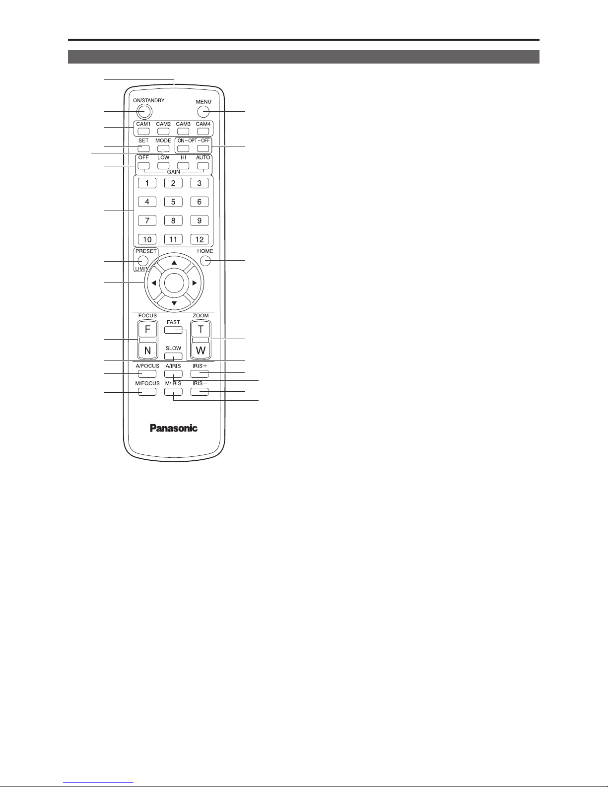
1. ON/STANDBY button <ON/STANDBY>
Each time this is pressed for 2 seconds, operation switches between
turning on the unit’s power and establishing the standby status.
2. Signal transmission window
3. MENU button <MENU>
Each time this is pressed for 2 seconds, operation switches between
displaying the unit’s camera menu and exiting the camera menu.
When it is pressed quickly (for less than 2 seconds) while a camera
menu is displayed, the setting change is canceled.
Furthermore, the pan and tilt movement range limits (limiters) are set
and released by operating the <PRESET/LIMIT> button and the pan/
tilt buttons (<4> <5> <b> <a>).
For details, refer to “Setting/releasing the limiters” (→ page 132).
4. CAM1 to CAM4 buttons
<CAM1> <CAM2> <CAM3> <CAM4>
Selects a camera to be operated.
Once a button has been selected, the unit corresponding to the
selected button can be operated.
5. SET button <SET>
If this button is held down for 2 seconds when the [AWB A] memory or
[AWB B] memory has been selected for the white balance adjustment,
the black balance is adjusted automatically and registered in the
memory selected.
When this button is pressed for under 2 seconds, only the white
balance is adjusted automatically.
6. MODE button <MODE>
This is used to select the video signals which are output from the unit.
Each time it is pressed, the signals are switched between the color
bar signals and camera video signals.
<NOTE>
• When [Audio] is set to [On] and the color bar is displayed, a test
sound (1 kHz) is output. Be cautious of the volume on external
devices.
7. GAIN button <OFF> <LOW> <HI> <AUTO>
These are used to set the gain.
The gain increase can be set in three steps using the <OFF>, <LOW>
and <HI> buttons.
<LOW> is set to 9 dB, and <HI> is set to 18 dB.
When the <AUTO> button is pressed, the AGC function is activated,
and the gain is adjusted automatically depending on the light quantity.
The maximum gain of the AGC function can be set using the camera
menu.
8. Preset memory call buttons <1> to <12>
These are used to call the information on the unit’s directions and
other settings, which have been registered in the unit’s preset
memories No.1 to No.12, and reproduce those settings.
Settings in preset memories No.13 and above cannot be called from
the wireless remote control.
9. PRESET/LIMIT button <PRESET/LIMIT>
This is used to register the settings in the preset memories or set or
release the limiters.
When a preset memory call button is pressed while the <PRESET/
LIMIT> button is held down, the information on the unit’s current
direction and other settings is registered in the call button.
Preset memory call buttons <1> to <12> correspond to the unit’s No.1
to No.12 preset memories.
Furthermore, the pan and tilt movement range limits (limiters) are set
and released by operating the <PRESET/LIMIT> button, <MENU>
button and the pan/tilt buttons (<4> <5> <b> <a>).
For details, refer to “Setting/releasing the limiters” (→ page 132).
10. Pan‑tilt buttons and menu operation buttons
<4> <5> <b> <a> <M>
1) These are used to change the unit’s direction.
The unit is tilted in the up/down direction using the <4> and <5>
buttons and panned in the left/right direction using the <b> and
<a> buttons.
The <M> button does not work during tilting and panning.
When the <4> or <5> and <b> or <a> buttons are pressed at the
same time, the unit moves diagonally.
2) The buttons are used for menu operations when the unit displays
the camera menus.
Use the <4> , <5> (<b>, <a>) buttons to select the menu items.
When a selected item has a sub-menu, the sub-menu will be
displayed by pressing the <M> button.
When the cursor is aligned with a particular item and the <M>
button is pressed on the setting menu at the bottom hierarchical
level, the setting of the selected item blinks.
When the <M> button is pressed after the setting has been
changed using the <4> and <5> (<b> and <a>) buttons, the
setting stops blinking, and the new setting is entered.
A setting for a regular menu item is reflected immediately if it is
changed while it is still flashing.
If the <MENU> button is pressed quickly (for less than 2 seconds)
while the setting is in the blinking status, the change will be
canceled, and the setting selected prior to the change will be
restored.
Wireless remote control (not supplied)
24
Parts and their functions (continued)

<NOTE>
• To prevent malfunctioning, there are a number of menu items
([Scene], [Format] and [Frequency]) whose setting is not reflected
immediately even if it is changed while it is still flashing.
It is reflected only after the <M> button has been pressed, causing
the setting to stop flashing and the new setting to be entered.
• A confirmation screen appears before the settings of some menu
items are to be entered.
11. FOCUS button <F> <N>
These are used to adjust the lens focus manually when the manual
setting is established for the lens focus.
The focus is adjusted in the far using the <F> button and in the near
using the <N> button.
12. A/FOCUS button <A/FOCUS>
This is used when automatically adjusting the lens focus.
13. M/FOCUS button <M/FOCUS>
This is used when manually adjusting the lens focus.
The FOCUS buttons (<F> and <N>) are used when performing the
actual adjustment.
14. OPT button <ON> <OFF>
Turn night mode on/off.
<NOTE>
• In night mode, video output will be in black and white. In addition,
the iris will be forcibly opened.
• White balance adjustment is not possible in night mode.
• ND filter switching is not possible in night mode.
15. HOME button <HOME>
When this is pressed for 2 seconds, the unit’s direction (panning or
tilting) returns to the reference position.
16. ZOOM button <T> <W>
These are used to adjust the lens zoom.
The zoom is adjusted in the wide-angle using the <W> button and in
the telephoto using the <T> button.
17. FAST button <FAST>
This is used to change the movement speed at which the panning,
tilting, zooming and focusing operations are performed to the high
speed.
<NOTE>
• The operating speed for panning and tilting when the preset
memory settings have been called can be changed using the
“Preset Speed” item of the camera menu.
18. SLOW button <SLOW>
This is used to change the movement speed at which the panning,
tilting, zooming and focusing operations are performed to the low
speed.
19. A/IRIS button <A/IRIS>
This establishes the setting for adjusting the lens iris automatically in
line with the light quantity.
20. M/IRIS button <M/IRIS>
This establishes the setting for adjusting the lens iris manually.
The <IRIS +> and <IRIS –> buttons are used when performing the
actual adjustment.
21. IRIS + buuton <IRIS +>
This is used to adjust the lens iris in the opening direction.
22. IRIS – button <IRIS –>
This is used to adjust the lens iris in the closing direction.
25
Parts and their functions (continued)
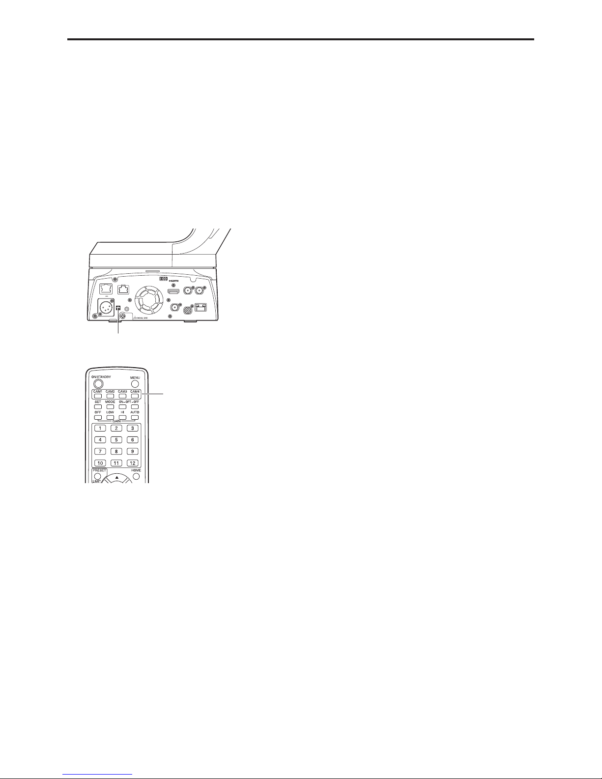
Setting the remote control IDs
The wireless remote control (optional accessory) is capable of operating
up to four units.
IDs are used to set which units are selected when the <CAM1>,
<CAM2>, <CAM3> and <CAM4> buttons on the wireless remote control
have been pressed.
• When operating a multiple number of these units using wireless
remote controls, set a different remote control ID for each control.
• When using one unit, set the remote control ID to “CAM1” unless the
setting needs to be changed.
Setting procedure
Operate the IR ID switches on the unit's rear panel, and select “CAM1”,
“CAM2”, “CAM3” or “CAM4” as the remote control ID. (→ page 19)
The IR ID switch settings “CAM1” to “CAM4” correspond to the <CAM1>
to <CAM4> buttons on the wireless remote control.
(The factory setting is “CAM1”.)
12 V IN
IR ID
AUDIO IN
RS-422
SERVICE
MONI OUT
12G SDI OUT
3G SDI OUT G/L IN
LAN
LINK ACT
SFP+
14G FIBER
IR ID switches
<CAM1> to <CAM4> buttons
26

Network settings
Use the Easy IP Setup Software to establish the
unit’s settings
The settings related to the unit’s network can be established using the
Easy IP Setup Software.
You can obtain Easy IP Setup Software (EasyIPSetup.exe) by
downloading it from the following website.
https://pro-av.panasonic.net/
To establish the settings for a multiple number of units, the settings must
be selected for each camera involved.
If the settings cannot be established using the Easy IP Setup Software,
select the settings separately for the unit and personal computer on the
Network setup screen [Network] of the setting menu. (→ page 110)
<NOTE>
• If, after the network settings have been established, another device in
the same network has the same IP address, the network operations
will not be performed properly.
Set the IP address in such a way that it does not duplicate an existing
IP address.
• Do not establish network settings from a multiple number of Easy IP
Setup Software programs at the same time for a single camera.
Similarly, do not perform the “Auto IP setting” operation of the
AW-RP150 remote camera controller at the same time.
The IP address settings may no longer be recognized as a result.
• The Easy IP Setup Software cannot be used from a different subnet
via a router.
• Use Easy IP Setup Software ver. 4.25R00 or newer.
1. Start the Easy IP Setup Software.
2. Click the [Search] button.
3. Click the MAC address/IPv4 address of the camera to be
set, and click the [Network Settings] button.
<NOTE>
• When a DHCP server is being used, the IP address allocated to the
unit can be checked by clicking the [Search] button of the Easy IP
Setup Software.
• If the same IP address is used for any additional cameras, the
numbers of the additional cameras will be displayed in the [IPv4
overlap] column of the cameras concerned.
• When the [Access Camera] button is clicked, the Live screen of the
selected camera is displayed.
• This unit does not support an IPv4/IPv6 switching function.
4. Input the network items, and click the [Save] button.
<NOTE>
• When a DHCP server is being used, [DNS] of the Easy IP Setup
Software can be set to [Auto].
• After the [Save] button is clicked, it takes about 2 minutes for the
settings in the unit to be completed. If the external DC power supply
or LAN cable is disconnected before the settings are completed, the
settings will be canceled. In this case, repeat the steps to establish the
settings.
• When a firewall (including software) has been introduced, enable
access to all the UDP ports.
27
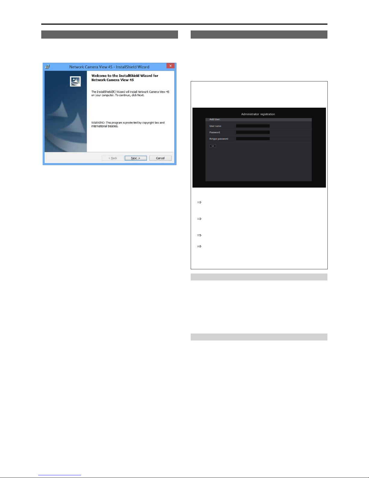
Installing the plug‑in viewer software
To view IP images from the unit on a web browser, the "Network
Camera View 4S" plug-in viewer software (ActiveX
®
) must be installed.
The plug-in viewer software can be installed directly from the unit.
<NOTE>
• [Automatic installation of viewer software] is set to [On] at the time of
purchase, allowing you to install directly from the unit. If a message
appears in the web browser's information bar, see page 142.
• When you display the Live screen [Live] on the personal computer for
the first time, the installation screen for the plug-in viewer software
(ActiveX) appears. Follow the instructions on the screen to perform
installation. (only when using Windows Internet Explorer 11)
• If the plug-in viewer software (ActiveX) installation screen continues
to appear when switching screens, even after it is installed, restart the
personal computer.
• A license is required for the plug-in viewer software for each personal
computer on which it is installed. You can view the number of times
the plug-in viewer software was automatically installed in the [Product
info.] tab of the Maintenance screen [Maintenance] (→ page 122).
For details on licenses, consult your local dealer.
• To uninstall the plug-in viewer software, select [Control Panel] [Programs] - [Uninstall a program] in Windows, and remove "Network
Camera View 4S".
User authentication
The unit can be configured to allow access from the internet. To
prevent infringement of privacy and personality rights, information leaks,
and other issues concerning unauthorized access by third parties, we
recommend enabling the user authentication function upon installation.
We also recommend using DIGEST authentication when connecting to a
device that supports DIGEST authentication.
Preparation:
1. Startup the web browser and display the “Live” page on a PC.
2. Click “Setup” button and then click “User mng.” button.
The user authentication window will be displayed.
A Select “On” for “User auth.”
*
Set to “Off” by default.
Then click “Set” button.
B (When using a device that supports DIGEST authentication)
Select “Digest” for “Authentication”.
Then click “Set” button.
C Register a new user name and password.
*
Select “1. Administrator” for the access level.
Then click “Set” button.
D Delete the default user name.
Click the “Delete” button after selecting the user name to be
deleted (“admin[1]”).
*
Depending on the model used, the screens shown in the
explanations may differ to the actual camera screens.
User name and password management
• Use a combination of characters and numbers that is difficult to
guess.
Avoid using a string of the same characters, such as “11111”, birth
dates, or telephone numbers.
For details on valid characters and lengths, refer to “User
authentication screen” (→ page 107).
• Change user names and passwords periodically.
• Make sure to manage the configured user names and passwords.
• Delete all user names that do not have an assigned user.
After changing the user name/password
Also change the user names and passwords registered to the following.
Refer to the operating instructions provided with your camera for further
information about the settings used for your camera.
• Remote camera controller (AW-RP150)
• Browsers and applications on computers, tablets, and smartphones.
28
Setting the remote control IDs (continued)

Basic shooting operations
1. Set the subject brightness to the appropriate level.
2. Turn on the power of all the units and devices in the
system.
3. Select the unit to be operated.
Even when using only one unit, it must still be selected from the
wireless remote control or controller.
4. Select the shooting mode.
One of four shooting modes (Scene1, Scene2, Scene3 or Scene4)
— whichever one will best suit the shooting conditions — can be
selected.
The shooting modes are set by the user.
For details of the factory settings, refer to pages 66 to 71.
Select the mode that satisfies the shooting conditions and suits your
preferences.
When continuing to shoot in the same circumstances, there is no
need to select another mode.
5. Start shooting.
(After shooting, turn off the power of all the units and
devices in the system.)
<NOTE>
• Some of the initial settings are auto settings and cannot be operated
manually. To operate them manually, switch from the auto settings to
the manual settings as required.
If the settings have already been changed and the original settings are
to be restored, refer to the “What to do when encountering problems
in the basic shooting operations” (→ page 33) and “Camera screen”
(→ page 43) in “Camera menu items”.
How to turn the power on and off
Turning the power on
When performing operations from a wireless
remote control
1. Set all the power switches of the units and devices
connected in the system to ON.
• This unit does not have a power switch.
When power is supplied to it, the status display lamp will light
orange, and the unit is set to the Standby mode.
<NOTE>
• Under factory default conditions, the unit will be in Standby mode
when power is supplied for the first time. (Status display lamp: Lit
orange)
• When the power supply is cut off while the unit is in Standby mode,
the unit will be in Standby mode the next time power is supplied.
(Status display lamp: Lit orange)
• When the power supply is cut off while the unit is in Power ON
mode, the unit will be in Power ON mode the next time power is
supplied. (Status display lamp: Lit green)
2. Press one of the <CAM1> to <CAM4> buttons on the
wireless remote control to select the unit.
3. Press the <ON/STANDBY> button on the wireless remote
control for about 2 seconds.
The Power ON mode is established, images are output, and control
can be exercised.
• The unit’s status display lamp now lights up green.
<NOTE>
• It takes maximum 30 seconds per unit for the initial settings
operation to be completed. During this period, the unit cannot be
operated.
(Status display lamp: Lit orange)
4. If a multiple number of units are going to be used, repeat
steps 2 and 3 as required.
The unit’s status display lamp blinks green when a signal matched by
the remote control ID has been received, and it blinks orange when a
signal that is not matched by the remote control ID has been received.
<NOTE>
• When operation is transferred to the Standby mode:
The current zoom, focus and iris positions are stored in the memory
(Power ON preset).
• When operation is transferred to the Power ON mode:
The zoom, focus and iris are adjusted to the positions which were
stored in the memory (Power ON preset) when operation was
transferred to the Standby mode.
When performing operations from a controller
When using an AW‑RP150
Refer to the operating instructions for the controller.
When using a commercially available controller
Refer to the operating instructions for the controller.
Turning the power off
When performing operations from a wireless
remote control
1. Press one of the <CAM1> to <CAM4> buttons on the
wireless remote control to select the unit.
2. Press the <ON/STANDBY> button on the wireless remote
control for about 2 seconds.
The unit enters Standby mode.
• The unit’s status display lamp now lights up orange.
3. If a multiple number of units are going to be used, repeat
steps 1 and 2 as required.
4. Set all the power switches of the units and devices
connected in the system to OFF.
• This unit does not have a power switch.
<NOTE>
• When operation is transferred to the Standby mode:
The current zoom, focus and iris positions are stored in the memory
(Power ON preset).
• When operation is transferred to the Power ON mode:
The zoom, focus and iris are adjusted to the positions which were
stored in the memory (Power ON preset) when operation was
transferred to the Standby mode.
When performing operations from a controller
When using an AW‑RP150
Refer to the operating instructions for the controller.
When using a commercially available controller
Refer to the operating instructions for the controller.
29

Up to four units can be operated using one wireless remote control.
Up to five units can be operated using one controller.
Select the unit (or units) to be operated from the wireless remote control
or controller.
Even when using only one unit, it must still be selected.
When performing operations from a wireless
remote control
To select the unit using the wireless remote control, the IR ID switches
on the unit’s back panel must be set.
For details of the IR ID switch settings, refer to page 19 and page 26.
1. Press the <CAM1>, <CAM2>, <CAM3>, or <CAM4>
button.
The unit’s status display lamp blinks green when a signal matched by
the remote control ID has been received, and it blinks orange when a
signal that is not matched by the remote control ID has been received.
When performing operations from a controller
When using an AW‑RP150
Refer to the operating instructions for the controller.
Selecting the units
30
 Loading...