

Page 1
Operating Instructions
Excerpted Version
Installation Instructions provided
4K Integrated Camera
Model No.
Model No.
Model No.
Model No.
AW‑UE150WP
AW‑UE150KP
AW‑UE150WE
AW‑UE150KE
Before installing and using this product, be sure to read “Read this rst!” (pages 4, 25 to 27).
ENGLISH
Excerpted Version
FRANÇAIS
ESPAÑOL
DEUTSCH
ITALIANO
PУССКИЙ
Before operating this product, please read the instructions carefully and save this manual for future use.
PJ EJ
SS1018YM0 -FJ
Printed in Japan
This manual contains information excerpted from the Operating Instructions.
For more information, please visit the Panasonic website (https://pro-av.panasonic.net/manual/en/index.html), and
refer to the Operating Instructions.
Avant d’installer et d’utiliser cet appareil, s’assurer de lire la section « Lire ces informations en premier ! » (pages 4, 28 à 30).
Pour de plus amples informations, visiter le site Web de Panasonic (https://pro-av.panasonic.net/manual/en/index.
html) et consulter le mode d’emploi et les instructions d’installation.
Antes de instalar y usar este producto, asegúrese de leer “Lea esto primero!” (páginas 4, 31 a 33).
Si desea obtener más información, visite el sitio web de Panasonic (https://pro-av.panasonic.net/manual/en/index.
html) y consulte las instrucciones de funcionamiento y las instrucciones de instalación.
Bitte lesen Sie sorgfältig „Bitte lesen Sie zuerst diesen Hinweis!“ vor der Installation und Nutzung dieses Produkts. (Seiten 5, 34 bis 35).
Weitere Informationen nden Sie auf der Panasonic-Webseite (https://pro-av.panasonic.net/manual/en/index.
html), in der Bedienungsanleitung und in der Installationsanleitung.
Prima di installare e utilizzare il prodotto, assicurarsi di leggere “Leggere prima quanto segue!” (pagine 5, 36 a 37).
Per maggiori informazioni, visitare il sito Web Panasonic (https://pro-av.panasonic.net/manual/en/index.html) e
fare riferimento alle istruzioni per l’uso e alle istruzioni per l’installazione.
Перед установкой и использованием данного изделия ознакомьтесь с информацией в разделе «Прочитайте
нижеследующее до начала эксплуатации!» (стр. 5, 38 до 39).
Для получения дополнительной информации посетите веб-сайт Panasonic (https://pro-av.panasonic.net/
manual/en/index.html) и обратитесь к инструкции по эксплуатации и инструкции по установке.
ENGLISH
DVQX1709ZA
Page 2
български
Посетете следния уебсайт относно информация
за безопасността и важни уведомления за
продукта.
Latviešu
Lai iegūtu informāciju par drošību un skatītu
svarīgus paziņojumus par šo produktu, apmeklējiet
tālāk norādīto tīmekļa vietni.
Hrvatski
Čeština
Dansk
Nederlands
Eesti
Suomi
Ελληνικά
Magyar
Za sigurnosne informacije i važne obavijesti o
proizvodu posjetite sljedeću internetsku stranicu.
Na následujícím webu najdete bezpečnostní
informace a důležité poznámky k tomuto produktu.
Besøg følgende webside for sikkerhedsinformation
og vigtige bemærkninger vedrørende produktet.
Ga naar de volgende website voor
veiligheidsinformatie en belangrijke meldingen
over het product.
Toodet puudutava ohutusteabe ja oluliste märkuste
saamiseks külastage järgmist veebilehte.
Käy seuraavalla verkkosivulla saadaksesi
turvallisuustietoja ja tärkeitä tietoja liittyen
laitteeseen.
Για πληροφορίες σχετικά με θέματα ασφάλειας και
σημαντικές ειδοποιήσεις που αφορούν το προϊόν
σας, επισκεφτείτε τον ιστότοπο που ακολουθεί.
A termékkel kapcsolatos biztonsági információkért
és fontos értesítésekért látogasson el az alábbi
weboldalra.
Lietuvių
Polski
Português
Română
Slovensky
Slovenščina
Svenska
Jei reikia saugos informacijos ir svarbių pranešimų
apie gaminį, apsilankykite toliau nurodytoje
svetainėje.
Informacje o bezpieczeństwie i ważne informacje
o produkcie znajdują się w poniższej witrynie
internetowej.
Consulte o seguinte website para as informações
de segurança e importantes noticações sobre o
produto.
Vizitați următoarea pagină web pentru informaţii
de securitate și noticări importante cu privire la
produs.
Pre bezpečnostné informácie a dôležité
oznámenia súvisiace s produktom navštívte túto
webovú stránku.
Za varnostne informacije in pomembna obvestila v
zvezi z izdelkom obiščite naslednje spletno mesto.
Besök följande webbplats för säkerhetsinformation
och viktiga meddelanden om produkten.
https://pro-av.panasonic.net/manual/en/index.html
Trademarks and registered trademarks
• Microsoft®, Windows®, Windows® 7, Windows® 10, Microsoft
Edge, Internet Explorer
registered trademarks or trademarks of Microsoft Corporation in
the United States and other countries.
• Apple, Mac, Mac OS, OS X, iPhone, iPad, and Safari are
registered trademarks of Apple Inc., in the United States and other
countries.
• Android™ and Chrome™ browser are trademarks of Google LLC.
®
• Intel
and Intel® Core™ are trademarks or registered trademarks
of Intel Corporation in the United States and other countries.
®
• Adobe
• The terms HDMI and HDMI High-Definition Multimedia Interface,
• NDI
• Other names of companies and products contained in these
About copyright and licence
Distributing, copying, disassembling, reverse compiling, reverse
engineering, and also exporting in violation of export laws of the
software provided with this unit are expressly prohibited.
and Reader® are either registered trademarks or
trademarks of Adobe Systems Incorporated in the United States
and/or other countries.
and the HDMI Logo are trademarks or registered trademarks of
HDMI Licensing Administrator, Inc. in the United States and other
countries.
®
is a registered trademark of NewTek, Inc.
Operating Instructions may be trademarks or registered
trademarks of their respective owners.
®
, ActiveX® and DirectX® are either
Abbreviations
The following abbreviations are used in this manual.
• Microsoft
to “Windows 7”.
• Windows
“Internet Explorer”.
For the purposes of this manual, the model numbers of the units are
given as listed in the table below.
Illustrations and screen displays featured
®
Windows® 7 Professional SP1 32/64-bit is abbreviated
®
Internet Explorer® 11 32/64-bit is abbreviated to
Model number of unit
AW-UE150WP
AW-UE150KP
AW-UE150WE
AW-UE150KE
AW-RP150G AW-RP150
Model number given in
manual
AW-UE150
in the manual
• What is shown in the manual’s illustrations and screen displays
may differ from how it is actually appears.
• Functions which can be used by Windows Internet Explorer 11
only are indicated using the
• The screenshots are used in accordance with the guidelines of
Microsoft Corporation.
mark.
22
Page 3

Contents
Installation Instructions
Read this first! ....................................................................................... 4
Lire ces informations en premier !....................................................... 4
Lea esto primero! .................................................................................. 4
Bitte lesen Sie zuerst diesen Hinweis! ................................................ 5
Leggere prima quanto segue! .............................................................. 5
Прочитайте нижеследующее до начала эксплуатации! ............... 5
Installation precautions ........................................................................ 6
Before installation ................................................................................. 8
IR ID switch settings ............................................................................8
Service switch settings......................................................................... 8
How to install and connect the unit ..................................................... 9
When using the WV-Q105A (optional accessory).............................. 13
Removing the camera ......................................................................... 14
Operating Instructions
Stand-alone installation
(when the mount bracket is going to be used) ............................. 15
Stand-alone installation
(when the mount bracket is not going to be used) ...................... 17
When installing the unit on a desktop ................................................ 17
When mounting the unit on a tripod ...................................................17
Connections ......................................................................................... 18
Connecting an NDI|HX compatible switcher ......................................18
Connections with a controller (AW-RP150) .......................................19
System example 1 (Serial control) .....................................................20
System example 2 (IP control) ........................................................... 21
System example 3 (IP image transmission, PoE++).......................... 22
Appearance .......................................................................................... 23
Read this first! .................................................................................... 24
Note on grounding .............................................................................24
Read this first! (For AW-UE150WP, AW-UE150KP) .......................... 25
Read this first! (For AW-UE150WE, AW-UE150KE) .......................... 26
Lire ces informations en premier !
(Pour AW-UE150WP, AW-UE150KP) .............................................. 28
Lire ces informations en premier !
(Pour AW-UE150WE, AW-UE150KE) .............................................. 29
Lea esto primero! (Para AW-UE150WP, AW-UE150KP) ................... 31
Lea esto primero! (Para AW-UE150WE, AW-UE150KE) ................... 32
Bitte lesen Sie zuerst diesen Hinweis!
(Für AW-UE150WE, AW-UE150KE) ................................................ 34
Leggere prima quanto segue!
(Per AW-UE150WE, AW-UE150KE) ................................................ 36
Прочитайте нижеследующее до начала эксплуатации!
(Для AW‑UE150WE, AW‑UE150KE) ............................................... 38
Before use ............................................................................................ 40
Overview ............................................................................................ 40
Computer requirements ..................................................................... 40
Disclaimer of warranty .......................................................................41
Network security ................................................................................41
Features................................................................................................ 42
Accessories ......................................................................................... 43
Optional accessories .......................................................................... 43
Operating precautions ........................................................................ 44
Wireless remote control (optional accessory).................................. 46
Parts and their functions .................................................................... 47
Camera unit .......................................................................................47
Wireless remote control: AW-RM50G (not supplied) ......................... 54
Setting the remote control IDs ........................................................... 56
Network settings.................................................................................. 57
Use the Easy IP Setup Software to establish the unit’s settings........ 57
Setting the initial account ................................................................... 58
Installing the plug-in viewer software ................................................. 58
How to turn the power on and off ...................................................... 59
Turning the power on ......................................................................... 59
Turning the power off ......................................................................... 59
Troubleshooting .................................................................................. 60
Specifications ...................................................................................... 69
Index ..................................................................................................... 70
Page 4
Installation Instructions
Read this first!
WARNING:
To prevent injury, this apparatus must be securely attached to
the floor/wall in accordance with the installation instructions.
WARNING:
Installation should only be performed by qualified installation
personnel.
Improper installation may result in the entire apparatus falling
down and causing injury.
indicates safety information.
Lire ces informations en premier !
AVERTISSEMENT:
Pour éviter tout risque de blessures, l’appareil doit être
solidement fixé au plancher/mur conformément aux instructions
d’installation.
AVERTISSEMENT:
L’installation ne doit être effectuée que par du personnel
d’installation qualifié.
Une mauvaise installation peut avoir pour conséquence la chute
de l’appareil et provoquer des blessures.
ENGLISH
CAUTION:
This camera intended for use only with the Mount Bracket
enclosed with the unit and Panasonic Direct Ceiling Mount
Bracket, WV-Q105A.
Use with other apparatus is capable of resulting in instability
causing possible injury.
FRANÇAIS
ATTENTION:
Cette caméra est conçue pour être utilisée uniquement avec la
potence de fixation fournie avec l’appareil ou avec la potence de
fixation directe au plafond Panasonic WV-Q105A.
L’utilisation de tout autre dispositif risque de se traduire par une
instabilité et être cause de blessures à des personnes.
Informations concernant la sécurité.
Lea esto primero!
ADVERTENCIA:
Para evitar heridas, este aparato debe estar firmemente
instalado al piso/pared de acuerdo con las instrucciones de
instalación.
ADVERTENCIA:
La instalación solamente debe llevarla a cabo personal
cualificado.
Una instalación incorrecta podría provocar la caída del
dispositivo y causar lesiones.
indica información de seguridad.
ESPAÑOL
PRECAUCIÓN:
Esta cámara ha sido diseñada para ser utilizada solamente
con la ménsula de montaje suministrada con la unidad y con la
ménsula de montaje directo en el techo de Panasonic modelo
WV-Q105A.
La utilización con otros aparatos puede causar inestabilidad y
posibles lesiones.
4
Page 5
Installation Instructions
Bitte lesen Sie zuerst diesen Hinweis!
WARNUNG:
Um Verletzungen zu verhüten, muss dieser Apparat gemäß
der Installationsanleitung sicher am Boden bzw. an der Wand
befestigt werden.
WARNUNG:
Die Installation darf nur durch qualifiziertes Personal ausgeführt
werden.
Fehlerhafte Installation kann zum Herunterfallen des Gerätes
und zu Verletzungen führen.
ist die Sicherheitsinformation.
Leggere prima quanto segue!
AVVISO:
Per prevenire ferite, questo apparecchio deve essere montato
saldamente al pavimento/muro in conformità alle istruzioni di
installazione.
AVVISO:
L’installazione deve essere realizzata unicamente da tecnici
qualificati.
Un’installazione incorretta può risultare nella caduta
dell’apparecchio con conseguenti danni alle persone.
DEUTSCH
VORSICHT:
Diese Kamera ist nur für den Einsatz mit der mitgelieferten
Montagehalterung und der Panasonic DeckenDirektmontagehalterung WV-Q105A vorgesehen.
Wird die Kamera mit anderen Apparaten verwendet, kann es zu
Instabilität kommen, die Verletzungen verursachen kann.
ITALIANO
PRECAUZIONE:
La videocamera deve essere utilizzata esclusivamente con la
staffa di montaggio in dotazione con l’unità e con la staffa per
montaggio diretto a soffitto WV-Q105A.
L’uso con altri apparecchi potrebbe causare instabilità ed
eventuali infortuni.
sono le informazioni sulla sicurezza.
Прочитайте нижеследующее до начала эксплуатации!
ОСТОРОЖНО:
Во избежание повреждения данный прибор должен
быть надежно закреплен на полу/стене в соответствии с
инструкцией по установке.
ОСТОРОЖНО:
Установка должна выполняться только квалифицированным
специалистом по установке.
Ненадлежащая установка может привести к падению всего
аппарата и получению травмы.
Данный знак обозначает информацию, относящуюся к технике безопасности.
Read this first <END>
ВНИМАНИЕ:
Данная камера предназначена для использования только с
монтажным кронштейном, поставляемым с устройством, и
монтажным кронштейном Panasonic для непосредственного
крепления к потолку WV-Q105A.
Использование с другим аппаратом может привести к
нарушению устойчивости и возможной травме.
РУССКИЙ
Page 6
Installation Instructions
Installation precautions
Panasonic does not accept any responsibility for accident or damage during installation if procedure in this manual is not
followed.
To installation personnel
Read the “Installation Instructions” thoroughly and then perform the operation correctly and safely.
Also, always read the “Read this first!” (→ page 4) of this manual as they contain important information.
After the installation, give the “Installation Instructions” to the customer to save for future use.
Ensure that the installation work complies with
the technical standards governing electrical
equipment.
This unit is for indoor use only.
It cannot be used outdoors.
Avoid installation in a location where the unit will be exposed to
direct sunlight for extended periods or near a cooling or heating
appliance.
Otherwise, deformation, discoloration, malfunctioning and/or
problems in operation may result. Operate the unit where it will not
be splashed or sprayed by water.
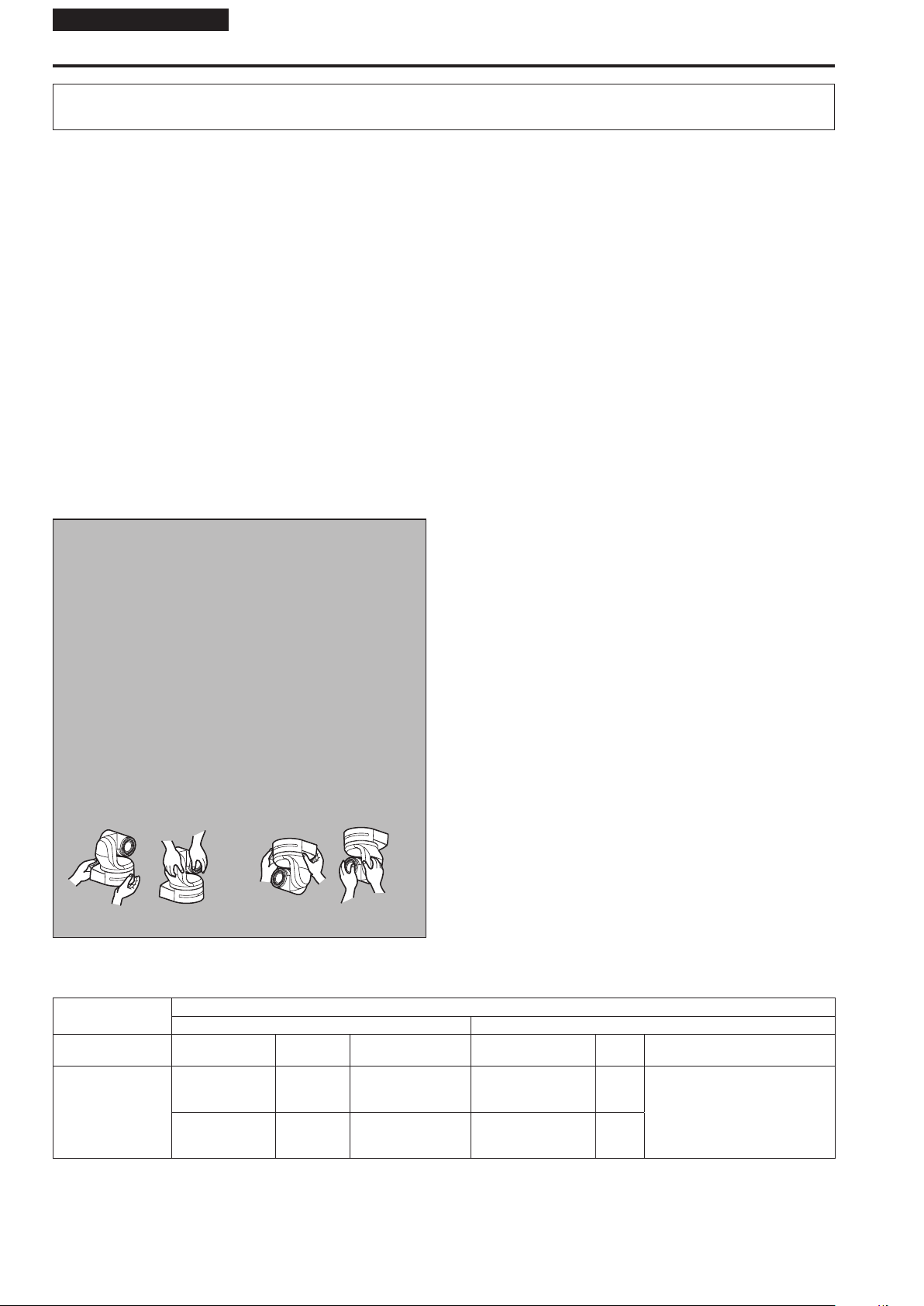
Use the unit with an installation where the unit
is suspended from an overhead surface or with
a stand-alone installation.
Do not use the unit on its side or tilted at an angle.
<NOTE>
• Be absolutely sure to use the four bracket mounting screws (M4) for
mounting the mount bracket. These are supplied with the unit.
Do not use wood screws, nails, etc.
In the case of a concrete ceiling, secure the unit using anchor bolts
(for M4) or AY plug bolts (for M4).
Recommended clamping torque
M4 : 1.47 N · m {15 kgf · cm}
• The withdrawal strength of the mounting location for each screw
must be at least 461 N {47 kgf}.
• When mounting the unit on a ceiling made of plasterboard, for
instance, if it is not strong enough to support its weight, either
reinforce the ceiling adequately or use the WV-Q105A direct ceiling
mount bracket, which is sold separately.
• When using a mount bracket which is sold separately, read the
handling instructions.
• Do not hold the camera head while undertaking the installation work.
Doing so may cause malfunctioning.
OK NG OK NG
OK NGOK NG
Concerning the installation location
Install the unit in a stable location which will not be susceptible to
shaking. If the unit is installed in a location which is susceptible to
shaking, this will cause the unit’s images to shake in turn.
Install the unit after conferring in detail with your dealer.
Install the unit on a ceiling that is strong enough (such as a concrete
ceiling).
If the unit is to be installed on a ceiling which is not strong enough,
reinforce the ceiling sufficiently first.
Do not install or use the unit in the following
kinds of locations.
• On walls (where the unit would be installed sideways)
• In locations (including places such as under the eaves of a
building) where the unit would be directly exposed to rain or water
• In locations such as kitchens where there are high concentrations
of steam and grease
• In outdoor locations or hot places where the temperature will
exceed 40 °C (104 °F)
• In cold locations where the temperature will drop below 0 °C
(32 °F)
• In locations where the humidity will exceed 85%
• In locations where chemicals are used such as near swimming
pools
• At sea, in coastal areas or in locations where corrosive gases are
emitted
• In locations where radiation, X-rays, or strong radio waves or
magnetic fields are generated
• In locations where the unit would be subject to a great deal
of vibration such as on board a vehicle or ship (this unit is not
designed to be used in vehicles)
• In locations where the temperature is subject to sudden changes
such as near the air outlet of an air conditioner or near a door
which allows the outside air to come in
What to avoid to ensure that the unit will
perform stably over a prolonged period
• Using the unit for a prolonged period in a location with high
temperature and humidity levels will cause its parts to deteriorate
and shorten its service life.
• Ensure that a cooling unit or heating unit will not blow any air
directly toward the installation location.
Desktop installation Hanging installation
AW-UE150
main unit
Mass Model No. Mass Mounting
Direct mount
Approx.
4.2 kg (9.24 lb)
(excluding mount
bracket)
(supplied
accessory)
WV-Q105A
(optional
accessory)
Applicable mount bracket Mounting onto the ceiling
Approx.
(0.77 lb)
Approx.
(0.33 lb)
6
0.35 kg
0.15 kg
Hanging/Desktop
For ceiling
Be absolutely sure to use the supplied brackets
and screws to install the camera.
• Do not mount the unit by employing any methods other than those
specified.
• Do not remodel the mounting bracket or mounting screws provided
with the unit.
Mounting conditions
Recommended
screws
M4 screws
(supplied accessory)
M4 screws
(supplied with the
WV-Q105A)
No. of
screws
4
4
Minimum withdrawal strength
(per screw)
461 N {47 kgf}
• Ensure that the mounting strength
can support a weight that is at least
five times the total mass of the
equipment, including the camera’s
main unit.
Page 7

Installation precautions (continued)
Installation Instructions
Before installation, always disconnect the DC
connector
When installing, always use the supplied components.
Do not disassemble or modify the wall mount adaptor.
Tightening up the mounting screws
• Tighten up the screws and bolts securely to the degree that is
appropriate for each of the materials used in the mounting location
and structures.
• After tightening up the screws and bolts, check that there is no
unsteadiness and that the parts have been tightened securely.
• Use the specified tools and tighten the screws firmly.
• Tighten up the screws using the specified torque driver. Do not
use electrical drivers or impact drivers.
When the unit is no longer going to be used, do
not leave it lying around, but be absolutely sure
to dispose of it properly.
For details on how to remove the unit, refer to “Removing the
camera” (→ page 14).
When installing, transferring or disposing of
the unit, be absolutely sure to hold it by its
pedestal area.
Problems may result if the camera head is held or rotated.
Do not attach a filter, hood, extender or other
parts to the unit.
Install the external DC power supply near the
main power outlet, and position it in such a
way that its power plug can be plugged into
and unplugged from the outlet easily.
When connecting the external DC power supply to a power outlet on
the ceiling or on any other surface where dust may collect, wipe off
the dust on the power plug at periodic intervals as an anti-tracking
measure.
Power switch
This unit does not have a power switch. When the power
is supplied, the pan, tilt, zoom and focusing operations are
performed.
sure to disconnect the power plug from the power outlet.
*1
Grounding
Before operating the unit, check that SIGNAL GND has been
securely grounded.
If there is a possibility of noise interference
Either wire the cables so that the power cable (ceiling light cord) of
AC 100 V
at least 1 meter (3.3 ft) apart.
Alternatively run each cable through its own metal conduit.
(The metal conduits must be grounded.)
*2
*3
Radio signal interference
If the unit is positioned near a TV or radio transmitting antenna or a
strong electrical field or magnetic field (such as that generated by a
motor, transformer or power lines), its images may be distorted and/
or the images may be affected by noise.
When connecting the cables, ensure that the
1
Before proceeding with maintenance, be absolutely
*
• Under factory default conditions, the unit will be in Standby
mode when power is supplied for the first time. (Status display
lamp: Lit orange)
• When the power supply is cut off while the unit is in Standby
mode, the unit will be in Standby mode the next time power is
supplied. (Status display lamp: Lit orange)
• When the power supply is cut off while the unit is in Power ON
mode, the unit will be in Power ON mode the next time power
is supplied. (Status display lamp: Lit green)
(For details, refer to “How to turn the power on and off”
(→ page 59).)
2
(AC 220 V
*
For AW-UE150WP, AW-UE150KP
For AW-UE150WE, AW-UE150KE
3
) or more, and the signal cable are placed
*
connector areas will not be subject to any load.
Doing so may cause malfunctioning.
Allowing the generated heat to escape
This unit allows the heat generated inside to escape from its
surfaces.
Do not install the unit in a location where it will be surrounded by
walls or other surfaces and where heat will be trapped.
In addition, the heat is dissipated to the bottom panel which will
warm up over time: This is normal and not indicative of any trouble.
PoE++ power supplies
Use a PoE++ [IEEE802.3bt Draft ver.2.0 standard (LLDP not
supported)] compatible hub or power supply device.
Network settings
The network function of this unit does not work unless an initial
account is set up (except when using the Easy IP Setup Software
(→ page 57)). A personal computer is required to set up an initial
account. (→ page 58)
<NOTE>
• Network connection with AW-RP150 also requires setup of an
initial account. When an initial account is not set up, AW-RP150
can detect but cannot control this unit.
Page 8
Installation Instructions
Before installation
Be sure to configure the switches on the connector panel and bottom of the unit before installing it.
Configuring the switches after the unit is installed may prove difficult.
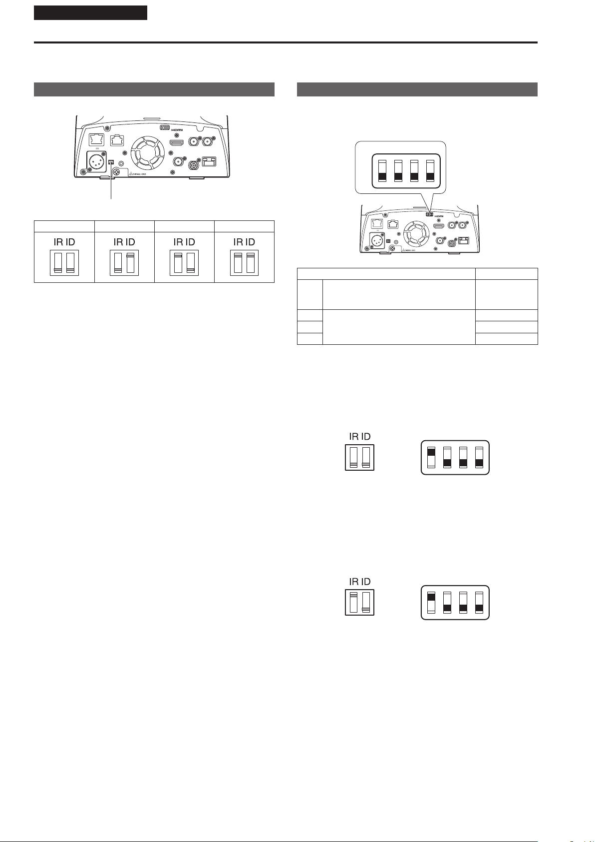
IR ID switch settings
The IR ID switches are located on the connector panel of the unit.
LAN
LINK ACT
RS-422
12 V IN
IR ID
AUDIO IN
IR ID switch
CAM1 CAM2 CAM3 CAM4
These are used to select the ID of the wireless remote control (optional
accessory). (→ page 56)
The IR ID switch settings “CAM1” to “CAM4” correspond to the <CAM1>
to <CAM4> buttons on the wireless remote control.
SERVICE
MONI OUT
3G SDI OUT G/L IN
12G SDI OUT
OPTICAL
Service switch settings
The service switches are located on the connector panel of the unit.
Perform switch settings before turning the unit on.
Service switch
SW1
SW2 SW3 SW4
ON
OFF
LAN
LINK ACT
12 V IN
IR ID
Function Factory settings
SW1 Switches for initialization
(Refer to the explanations in “Initialization 1”
and “Initialization 2”)
SW2
Always leave at OFF (used for factory
SW3 OFF
adjustments)
SW4 OFF
Initialization 1
• Reset the user authentication settings and host authentication settings
for network connection.
(This will delete all the registered user information (IDs/passwords)
and host information (IP addresses).)
• With the IR ID switches and service switches set as shown below, turn
on the power of the unit.
SERVICE
RS-422
AUDIO IN
MONI OUT
3G SDI OUT G/L IN
12G SDI OUT
OPTICAL
OFF
OFF
SW1
SW2 SW3 SW4
ON
OFF
<NOTE>
• When initialization is complete, the status display lamp on the front of
the unit blinks green. Restart the unit to confirm the initialization.
Initialization 2
• The unit is reset to the state it was in at the time of purchase. (All
camera menu setting values and network setting values are reset.)
• With the IR ID switches and service switches set as shown below, turn
on the power of the unit.
SW1
SW2 SW3 SW4
ON
OFF
<NOTE>
• When initialization is complete, the status display lamp on the front of
the unit blinks green. Restart the unit to confirm the initialization.
8
Page 9
Installation Instructions
How to install and connect the unit
Be absolutely sure to read through the “Read this first!” (→ page 4) and “Installation precautions” (→ pages 6 to 7).
The procedure given here is for the kind of installation where the unit is suspended from an overhead surface, but the same steps are followed for a
stand-alone installation.
If the ceiling panel is not strong enough to bear the unit’s weight, use the kind of mount bracket that is supported by anchor bolts
between the concrete ceiling and ceiling panel. The unit supports the WV-Q105A direct ceiling mount bracket which is used solely for
combination cameras. Use this bracket to install the unit. (→ page 13)
In a case like this, the holes (ø 60 mm (ø 2-3/8 inches)) for installing the direct ceiling mount bracket on the ceiling must be drilled in the
ceiling panel.
It is also recommended that you provide an inspection space or opening for access purposes in the area near where the equipment is
installed in order to facilitate installation and the wiring connections work.
For details on supplied accessories, refer to the page 43.
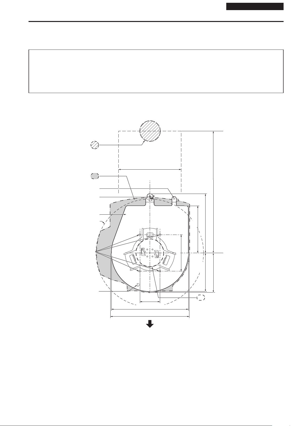
1. Check the mounting space.
• Refer to the illustration, and determine where the unit is to be installed and in which direction it should be mounted.
Factor in the unit mounting area and include space for the wires extending from its rear panel.
• The asterisk () in the illustration marks the position and dimensions of the hole for mounting the mount bracket.
Unit: mm (inch)
Through-hole for cable
ø 40 (ø 1-9/16)
(reference)
(Space for the wires from the
160 (6-5/16)
rear panel)
Unit mounting area
Hole for mounting the
main unit mounting screw
Hook for mounting the
drop-prevention wire
Mount bracket
Moving range of the camera head
(ø 246 (ø 9-11/16))
() Holes for mounting the mount
bracket: ø 4.5 (ø 3/16) × 4
Hole for checking the positioning
() 46
(1-13/16)
176 (6-15/16)
180 (7-3/32)
() 83.5
(Space for the wires)
320 (12-19/32) or more
108 (4-1/4)
90 (3-17/32)
88 (3-15/32) 136 (5-11/32)
Hole for installing the WV-Q105A
direct ceiling mount bracket
(ø 60 (ø 2-3/8))
The front panel of the unit on this side.
<NOTE>
• Before proceeding to install and connect the main unit, connect the LAN cable, HDMI cable, optical fiber multi cable and coaxial cables in the space
above the ceiling panel, and then pass the cables through the cable holes.
• For a power outlet which is used on the ceiling, be absolutely sure to take measures to deal with the tracking that may be caused by the accumulation
of dust and other foreign matter.
Page 10
Installation Instructions
How to install and connect the unit (continued)
2. Mount the mount bracket onto the installation surface.
• Use the bracket mounting screws (M4, bind-head: 10 mm (13/32 inches) long) supplied with the unit.
• For proper clamping torque, securely attach the screws using the specified tools.
Screw
diameter
M4 1.47 N · m {15 kgf · cm}
Clamping torque
Bracket mounting screws × 4 (supplied)
(M4, bind-head)
<NOTE>
• Use only the screws supplied with the unit. Do not use any other screws such as wood screws, nails, etc.
3. Attach the drop-prevention wire.
• Loop the circle part of the drop-prevention wire, which has been attached to the bottom panel of the unit, around the end of the hook part of the
mount bracket.
• Pull the drop-prevention wire, and check that it has been attached securely to the hook.
End of hook
Drop-prevention
wire
A Loop the circle part of the drop-
prevention wire around the end
of the hook part of the mount
bracket.
B Pull the wire, and check that
it is securely attached to the
hook.
<NOTE>
• Do not do this work while holding the camera head since doing so may result in malfunctioning of the unit.
• The drop-prevention wire is designed to be used for installation where the unit is suspended from an overhead surface so do not subject it to the
weight of units other than the unit.
10
Page 11
Installation Instructions
How to install and connect the unit (continued)
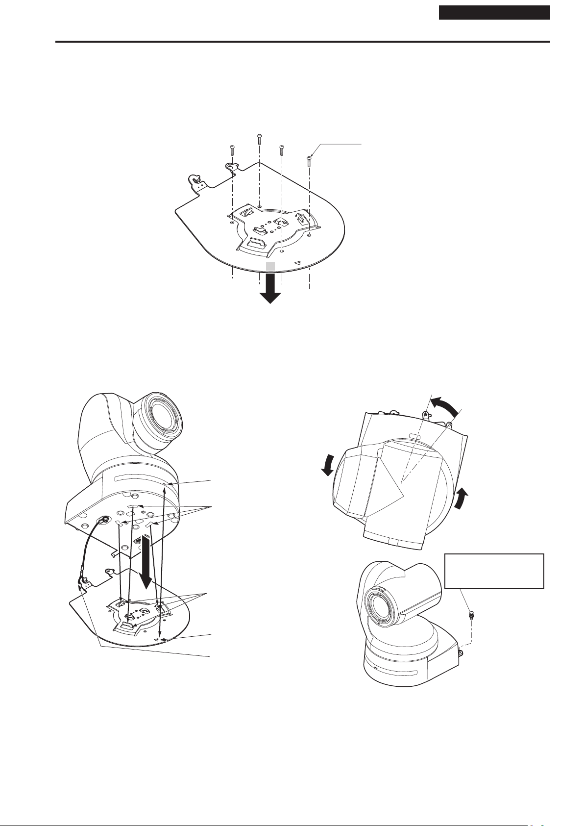
4. Mount the unit.
• Align the position of the hole for checking the positioning with the status display lamp.
• Align the holes on the camera main unit used to insert the bottom panel with the protrusions on the mount bracket used for inserting the camera,
push the bracket and camera firmly together, and rotate the main unit by about 20 degrees in the direction of the arrow.
• Secure the mount bracket to the unit using the main unit mounting screw (M3) as supplied.
• Attach the mount bracket securely with the prescribed tool using the clamping torque below.
• Be absolutely sure to verify that none of the screws are loose.
Screw
diameter
M3 0.78 N · m {8 kgf · cm}
Hole for checking
the positioning
On the mount
bracket: Protrusions
(×3) used for
inserting the camera
On the camera
main unit: Holes
(×3) used to insert
the bottom panel
Clamping torque
Approx. 20°
Status display lamp
Main unit mounting screw (M3 screw)
(with flat washer, spring washer)
<NOTE>
• Do not do this work while holding the camera head since doing so may result in malfunctioning of the unit.
• Use only the screws supplied. Do not use any other screws.
• Check that the unit has been mounted securely with no tilting or wobbling.
• The unit must be secured without fail using the main unit mounting screw before any of the cables are connected.
5. Check the mounting.
Check out the following points.
• The main unit mounting screw must be mounted securely.
• The unit must not tilt, and it must be mounted exactly.
• The unit must be securely installed.
• The unit pedestal part must not rotate even when an attempt
is made to turn it.
Page 12
Installation Instructions
How to install and connect the unit (continued)
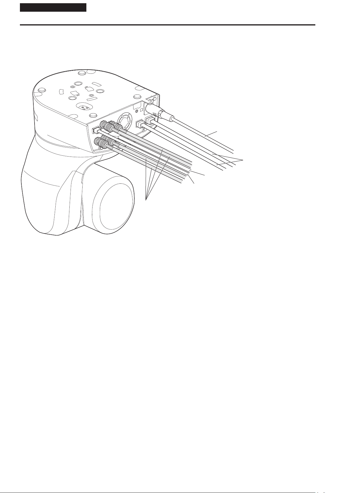
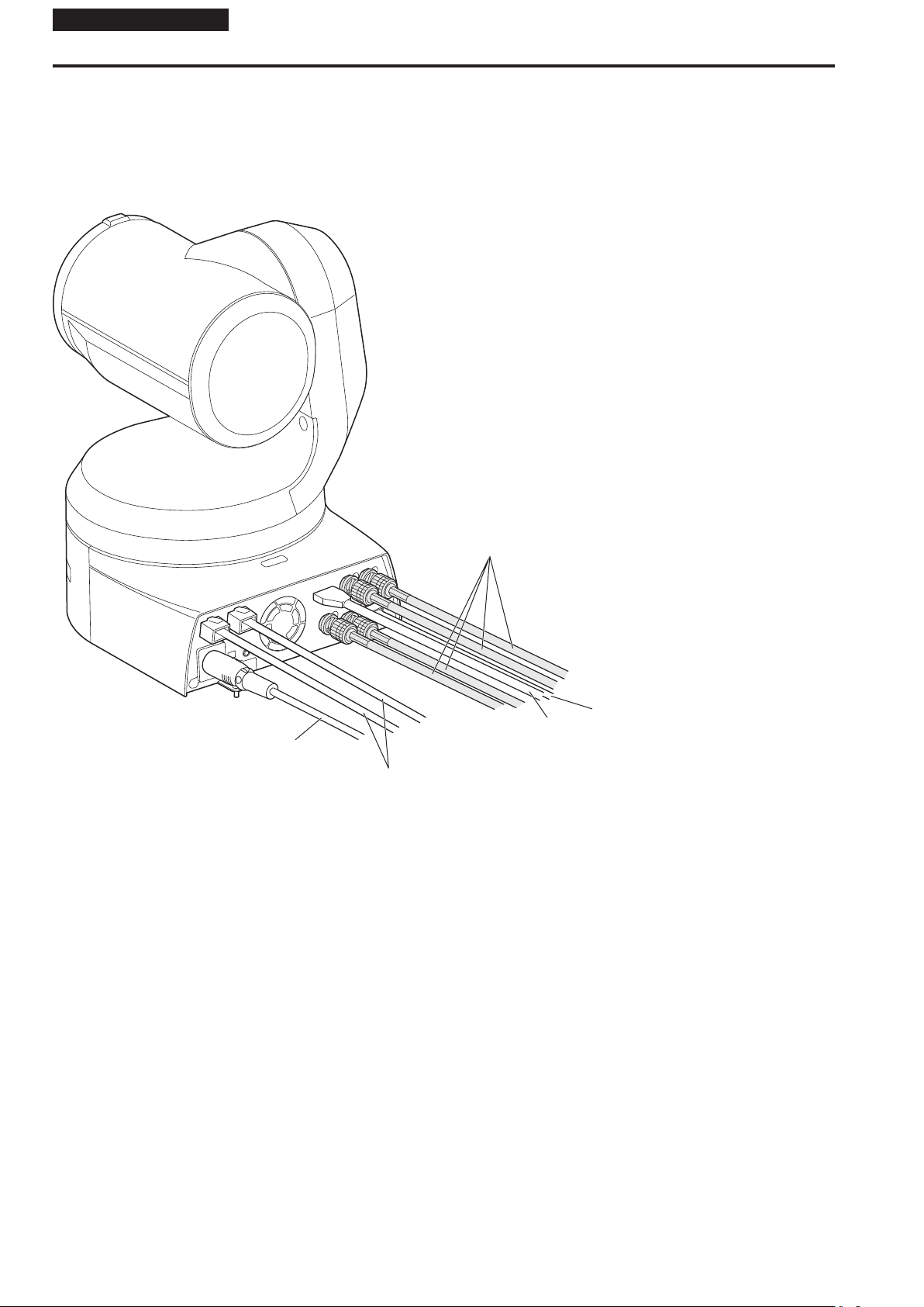
6. Connect the rear panel connectors.
<NOTE>
• Do not connect PoE cable to the RS-422 port.
• When Optical output is to be used, connect the recommended optical fiber module. (→ page 49)
• For details on recommended products, refer to the catalog or consult your local dealer.
DC cable (External DC power supply)
LAN cable
HDMI cable
Coaxial cable
Optical fiber multi cable
12
Page 13
Installation Instructions
How to install and connect the unit (continued)
When using the WV-Q105A (optional accessory)
It is recommended that you provide an inspection opening or other such space for access purposes in the area near where the equipment is installed in
order to facilitate installation and the wiring connections work.
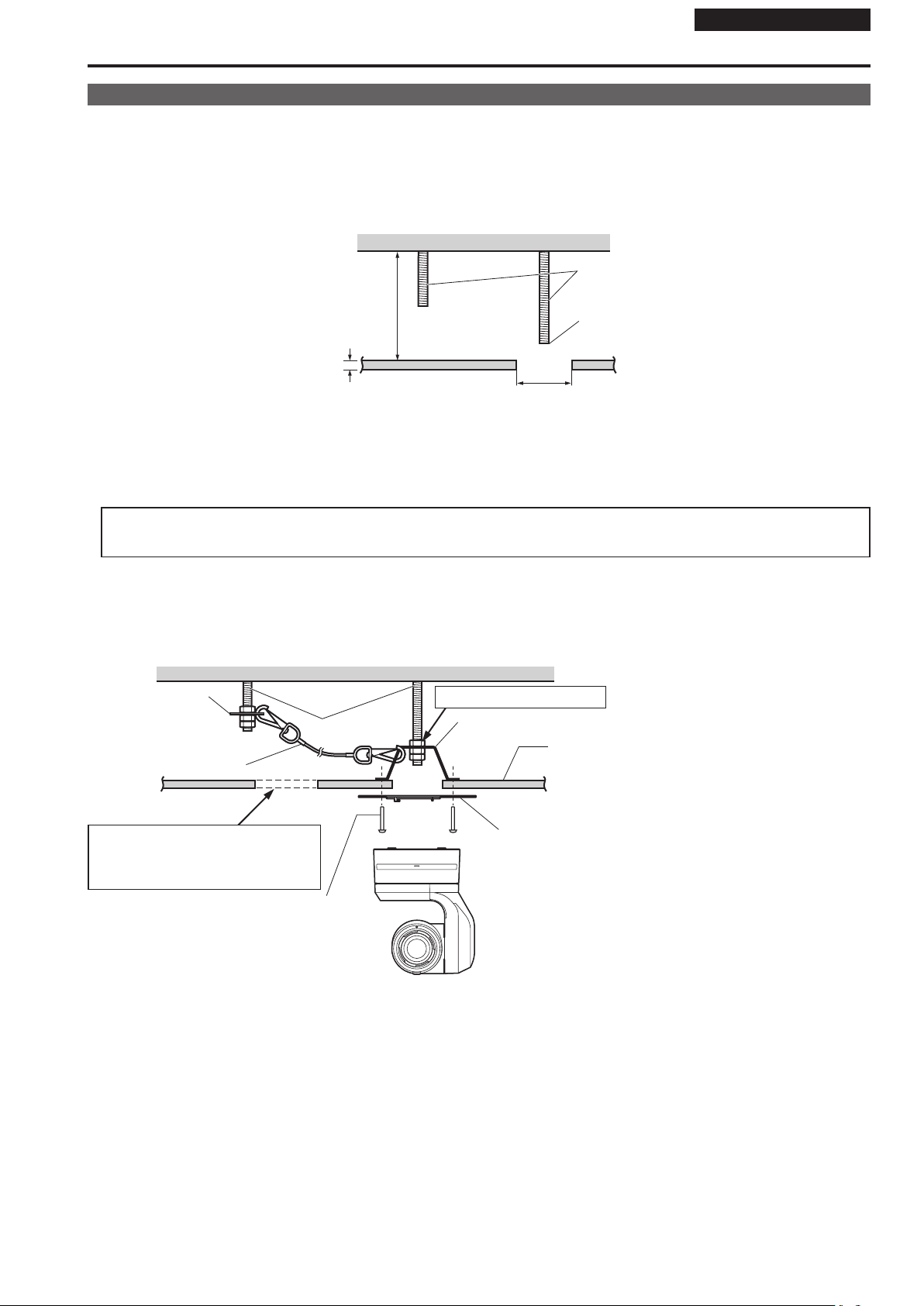
Before mounting the mount bracket, check that the installation location is strong enough to withstand the total mass (approx. 4.7
be exerted once the camera is mounted.
Use the mount bracket where the space between the ceiling panel and the concrete ceiling is at least 100 mm (3-15/16 inches) high.
The bracket can be mounted where the thickness of the ceiling panel ranges from 5 mm (3/16 inches) to 40 mm (1-9/16 inches).
The drop-prevention wire (supplied with the WV-Q105A) must be used when mounting the direct ceiling mount bracket.
Concrete ceiling
Anchor bolts
Height above ceiling panel:
At least 100 mm (3-15/16 inches)
Ceiling panel (plasterboard, etc. with a
thickness from 5 mm (3/16 inches) to
40 mm (1-9/16 inches))
ø 60 mm (2-3/8 inches)
(Withdrawal strength: 461 N {47 k
The anchor bolts must not protrude
beneath the ceiling panel.
kg (10.34 lb)) which will
g
f} or more)
1. Refer to the Operating Instructions of the WV-Q105A direct ceiling mount bracket, and attach the WV-Q105A as well as the
drop-prevention wire angle and drop-prevention wire supplied with the WV-Q105A to the anchor bolts.
Mounting the anchor bolts and direct ceiling mount bracket ()
This job is facilitated if the direct ceiling mount bracket is loosely secured to the ceiling panel in one place, and the direct ceiling mount bracket and
anchor bolts are vertically aligned before the nuts are tightened up.
2. First, remove the screws which were loosely fastened in step 1, and then align the camera mount bracket of the AW-UE150
with the screw holes in the WV-Q105A direct ceiling mount bracket and mount it in place.
• Use the mounting screws (the M4-L60 Phillips head screws with adhesive) supplied with the WV-Q105A as the mounting screws.
Space above the ceiling
Drop-prevention wire
angle (Supplied with
WV-Q105A)
Drop-prevention wire
(Supplied with WV-Q105A)
Inspection opening recommended
• The installation and wiring connection
work is facilitated if an inspection opening
is provided for access purposes.
Mounting screw × 4
(Supplied with WV-Q105A)
Anchor bolts
(): Fasten here using the nut.
Direct ceiling mount bracket WV-Q105A (optional accessory)
Plasterboard or other ceiling panel
Camera mount bracket
(Supplied with AW-UE150)
AW-UE150
3. Install the AW-UE150 camera by following the procedure starting with step 3 on page 10.
Page 14
Installation Instructions
Removing the camera
1. Turn off the circuit breaker and power.
2. Disconnect the cables.
Disconnect the DC cable, LAN cable, and HDMI cable, etc.
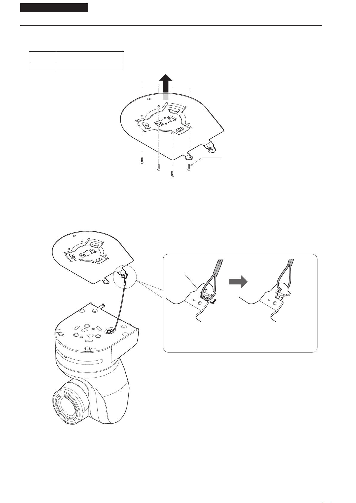
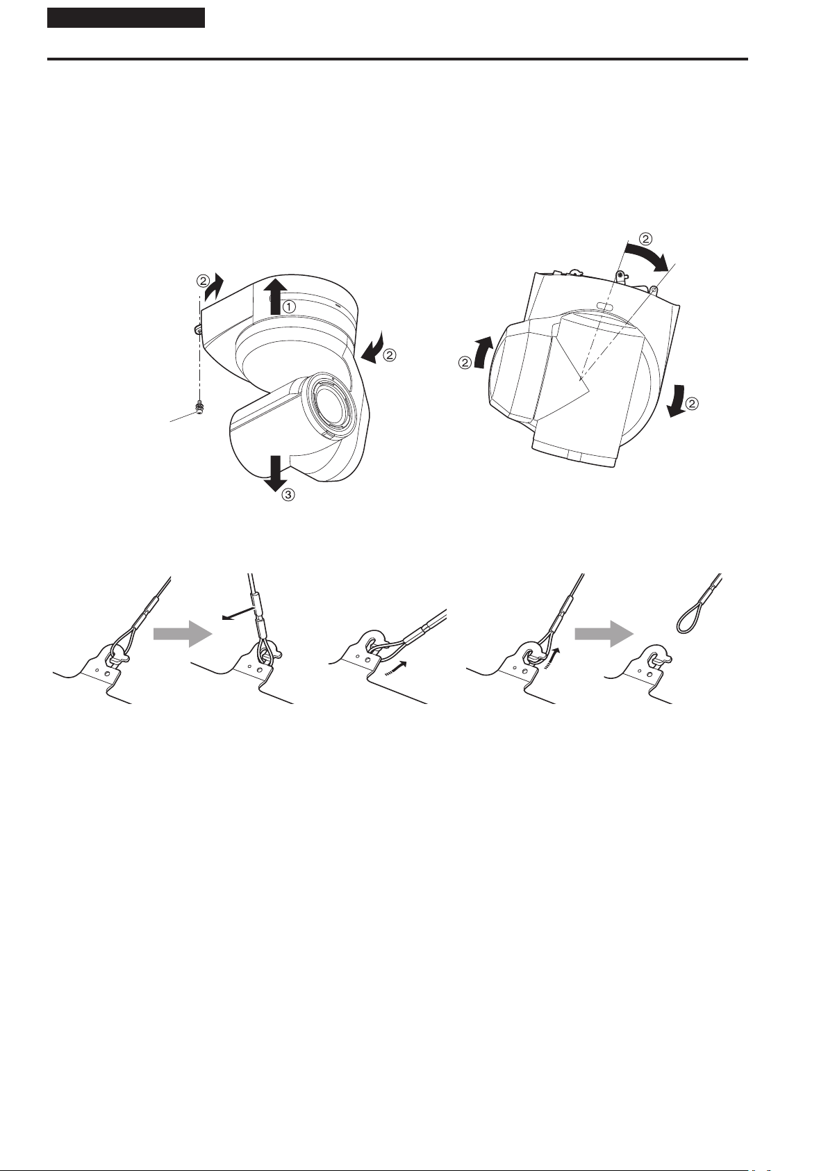
3. Remove the main unit mounting screw used to secure the unit and mount bracket.
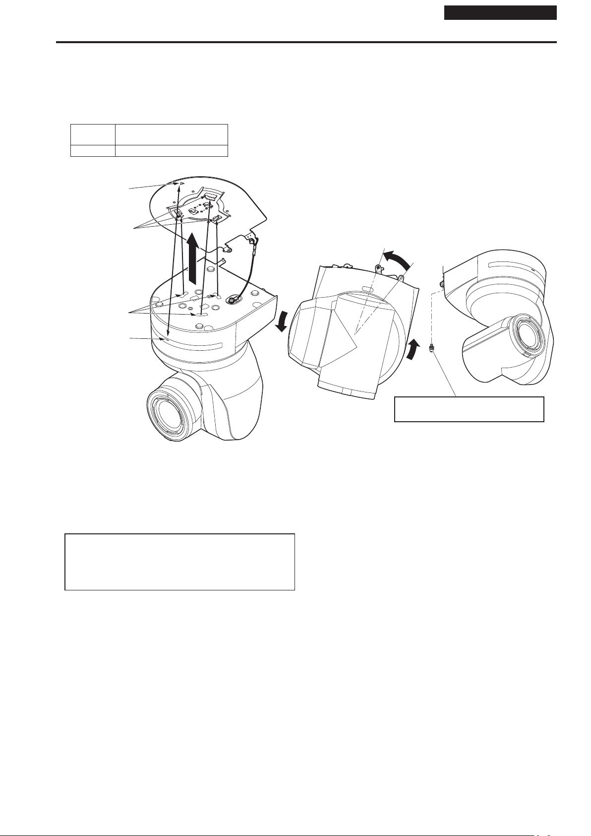
4. Push the unit (A). Turn it approximately 20 degrees away from the installed position (B), and remove it (C).
Main unit mounting
screw (M3 screw) (with
flat washer, spring
washer)
Approx. 20°
<NOTE>
• Do not do this work while holding the camera head since doing so may result in malfunctioning of the unit.
5. Disengage the drop-prevention wire from the mount bracket.
A Pull the dropprevention
wire in the direction
shown by the arrow
above.
B Twist the wire, and
remove the wire loop
through the opening in
the hook.
C Pull the wire in the direction
shown by the arrow above, and
simply pull it out.
14
Page 15
Installation Instructions
Stand-alone installation (when the mount bracket is going to be used)
The same steps are followed as for the kind of installation where the unit is suspended from an overhead surface (→ pages 9 to 12).
1. Check the mounting space.
<NOTE>
• As with installing the unit suspended from an overhead surface, carefully check the space where the unit will be mounted, and then decide if it is
appropriate to install the unit in that space.
2. Mount the mount bracket onto the installation surface.
Bracket mounting screws × 4 (supplied)
(M4, bind-head)
3. Attach the drop-prevention wire.
4. Mount the unit.
• Align the position of the hole for checking the positioning with the status display lamp.
• Align the holes on the camera main unit used to insert the bottom panel with the protrusions on the mount bracket used for inserting the camera,
push the bracket and camera firmly together, and rotate the main unit by about 20 degrees in the direction of the arrow.
• Secure the mount bracket to the unit using the main unit mounting screw (M3) as supplied.
Approx. 20°
Status display
lamp
On the camera main unit:
Holes (×3) used to insert
the bottom panel
Main unit mounting screw
(M3 screw) (with flat
washer, spring washer)
On the mount bracket:
Protrusions (×3) used for
inserting the camera
Hole for checking the
positioning
Attach the drop-prevention
wire.
Page 16
Installation Instructions
Stand-alone installation (when the mount bracket is going to be used) (continued)
5. Check the mounting.
6. Connect the rear panel connectors.
<NOTE>
• Do not connect PoE cable to the RS-422 port.
• When Optical output is to be used, connect the recommended optical fiber module. (→ page 49)
• For details on recommended products, refer to the catalog or consult your local dealer.
DC cable (External DC power supply)
Coaxial cable
Optical fiber multi cable
HDMI cable
LAN cable
16
Page 17
Installation Instructions
Stand-alone installation (when the mount bracket is not going to be used)
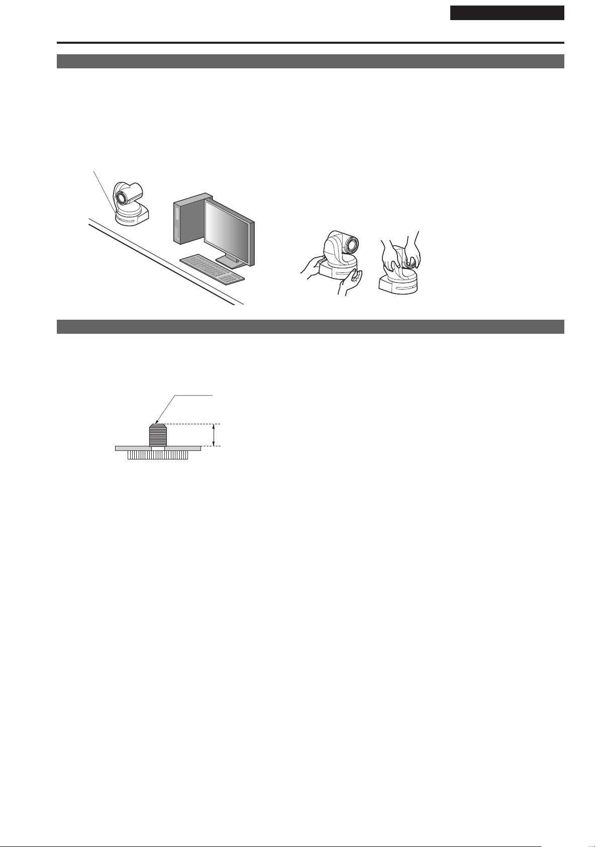
When installing the unit on a desktop
Place the unit flat on the surface.
<NOTE>
• Install the unit in a stable location which will not be susceptible to shaking. If the unit is installed in a location which is susceptible to shaking, this will
cause the unit’s images to shake in turn.
• Take care not to allow the unit to fall or otherwise be damaged during installation.
• When carrying the unit, do not hold it by its head.
• Do not take hold of the camera head or rotate it. Doing so may cause malfunctioning.
• Take care not to pull the connected cables. Doing so may cause the unit to fall and/or it may result in injury.
Ensure that the unit will not fall off.
OK NG
OK NG
When mounting the unit on a tripod
Attach the tripod to the threaded holes for mounting the camera on the camera’s bottom panel.
Place the tripod on a completely flat and level surface.
Tighten the screws by hand to mount the tripod securely.
Use screw for mounting the tripod that satisfy the following standard.
Screw for mounting tripod
1/4-20UNC, ISO1222 (6.35 mm (1/4 inches))
4.5 mm to 9 mm
(3/16 inches to 11/32 inches)
<NOTE>
• Do not install the unit where people will be passing back and forth.
• When using the unit mounted on a tripod, do not put the tripod high above the floor level.
• Mount the unit securely so there is no looseness. Looseness may cause the unit to fall off and/or result in injuries.
• When the unit is going to be used for a prolonged period of time, take steps to ensure that the unit will not topple or fall over and that it will not fall off
or fall down. After using the unit, restore the installation location to its original state without delay.
Page 18
Installation Instructions
Connections
Connecting an NDI|HX compatible switcher
AW-UE150
External DC power supply
Switching hub
AW-UE150
LAN cable
NDI|HX compatible switcher
Monitor Monitor
External DC
power supply
Remote Camera Controller
AW-RP150
18
Page 19
Connections (continued)
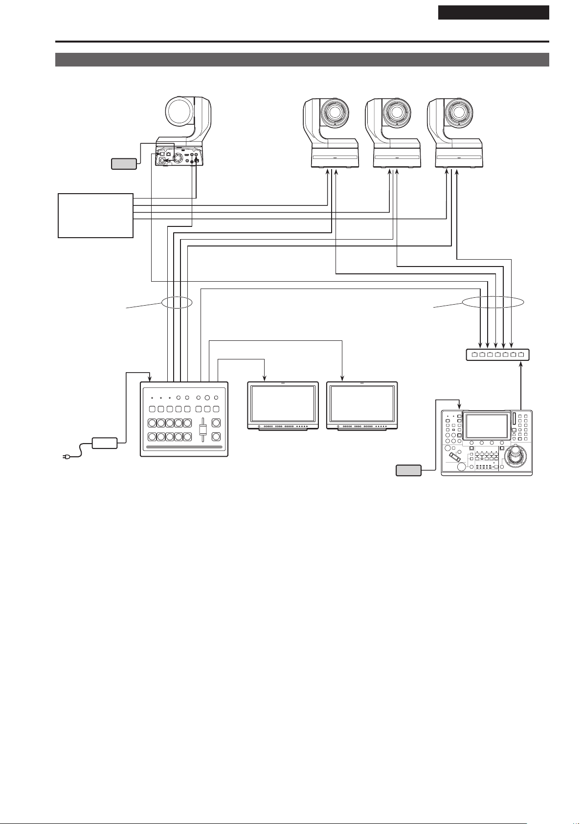
Connections with a controller (AW-RP150)
Example of connection for the function for cropping 4K images to HD images
AW-UE150 AW-UE150
3G SDI OUT
MONI OUT
External DC
power supply
Monitor
Installation Instructions
Monitor
3G SDI
ACTIVE THRU OUT
External DC
power supply
LAN cable
(Straight cable or cross
cable)
Max. 100 m (328 ft)
SDI IN
Remote camera controller
AW-RP150
LAN cable
(Straight cable or cross cable)
Max. 100 m (328 ft)
• Use a category 5e cable for the LAN cable.
Page 20
Installation Instructions
Connections (continued)
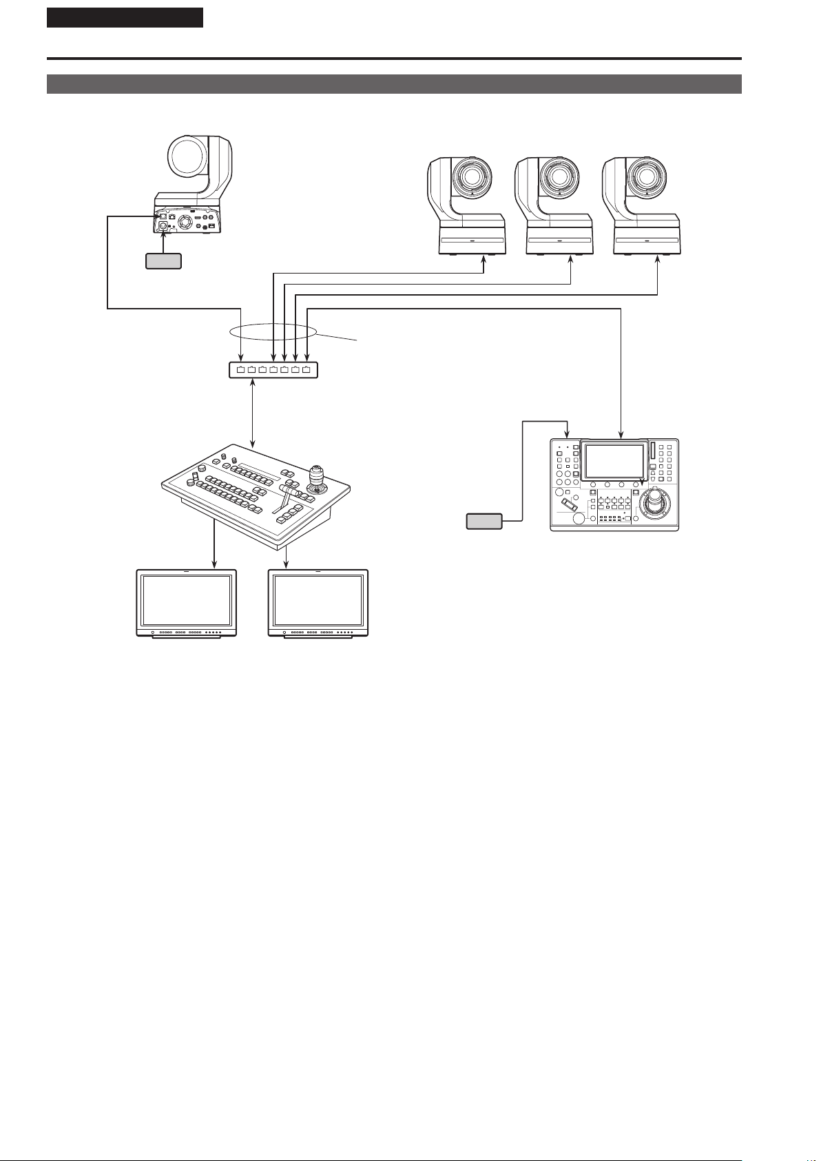
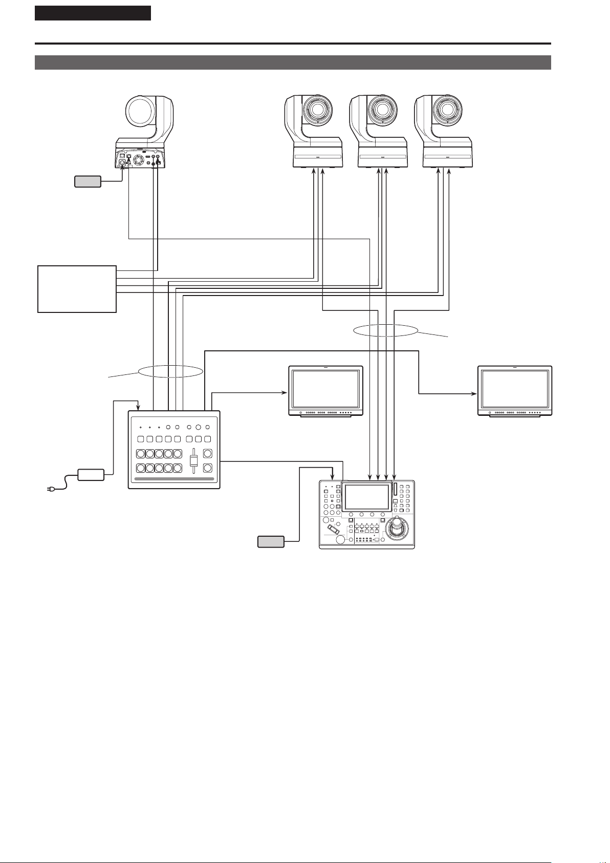
System example 1 (Serial control)
AW-UE150 AW-UE150
External DC
power supply
RS-422
connector
Genlock signal
generator
SDI video signal
Accessory
AC adaptor
Compact Live Switcher
AW-HS50
Pan-tilt head and camera
control signal (LAN straight
cable)
Monitor 1 Monitor 2
Monitor Monitor
System TALLY
External DC
power supply
Remote Camera Controller
AW-RP150
20
Page 21
Connections (continued)
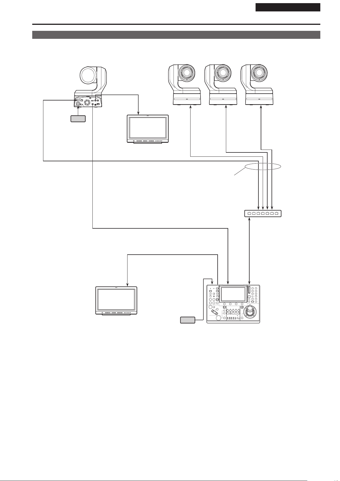
System example 2 (IP control)
AW-UE150 AW-UE150
External DC
power supply
LAN connector
Genlock signal
generator
Installation Instructions
SDI video signal
Accessory
AC adaptor
Compact Live Switcher
AW-HS50
Monitor 1
Monitor 2
Monitor Monitor
LAN cable
Switching hub
External DC
power supply
LAN cable
Remote Camera Controller
AW-RP150
Page 22
Installation Instructions
Connections (continued)
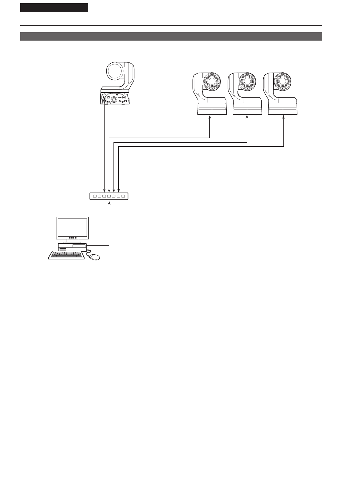
System example 3 (IP image transmission, PoE++)
AW-UE150
LAN
connector
AW-UE150
LAN cable
Personal computer
PoE++ compatible switching hub or PoE++ injector
22
Page 23

Appearance
Installation Instructions
Unit: mm (inch)
177 (6-31/32)
86.95 (3-7/16)
LAN
LINK ACT
12 V IN
266.6 (10-1/2)
210.5 (8-9/32)2 (3/32)
POWER STANDBY
182 (7-5/32)
213 (8-3/8)
RS-422
IR ID
AUDIO IN
SERVICE
MONI OUT
3G SDI OUT G/L IN
12G SDI OUT
OPTICAL
90.9 (3-19/32)
219.6 (8-21/32)
Rear panel view
Page 24

Operating Instructions
IR ID
AUDIO IN
Read this first!
Note on grounding
• Ground the unit via the <SIGNAL GND> ground connector.
to ground
connector on wall
outlet, ground
Ground connector
bar, etc.
24
Page 25

Operating Instructions
Read this first! (For AW-UE150WP, AW-UE150KP)
WARNING:
• To reduce the risk of fire or electric shock, do not expose this
equipment to rain or moisture.
• To reduce the risk of fire or electric shock, keep this equipment
away from all liquids. Use and store only in locations which are
not exposed to the risk of dripping or splashing liquids, and do
not place any liquid containers on top of the equipment.
WARNING:
Always keep the main unit mounting screw, bracket mounting
screws and drop-prevention wire mounting screw out of the
reach of infants and small children.
CAUTION:
Do not remove panel covers by unscrewing.
To reduce the risk of electric shock, do not remove the covers.
No user serviceable parts inside.
Refer servicing to qualified service personnel.
CAUTION:
In order to maintain adequate ventilation, do not install or place
this unit in a bookcase, built-in cabinet or any other confined
space. To prevent risk of electric shock or fire hazard due to
overheating, ensure that curtains and any other materials do not
obstruct the ventilation.
CAUTION:
To reduce the risk of fire or electric shock and annoying
interference, use the recommended accessories only.
CAUTION:
Check the installation at least once a year.
An improper installation could cause the unit to fall off resulting
in personal injury.
CAUTION:
Do not pick up and move the unit while the tripod is attached.
The fitting may break under the weight of the tripod, which may
result in injury.
ENGLISH
indicates safety information.
FCC NOTICE (USA)
Declaration of Conformity
Model Number: AW-UE150P
Trade Name: Panasonic
Responsible Party: Panasonic Corporation of North America
Two Riverfront Plaza, Newark, NJ 07102
Support contact: 1-800-524-1448
This device complies with part 15 of the FCC Rules.
Operation is subject to the following two conditions:
(1) This device may not cause harmful interference, and (2) this device must accept any interference received, including interference that may
cause undesired operation.
CAUTION:
This equipment has been tested and found to comply with the limits for a class A digital device, pursuant to Part 15 of the FCC Rules.
These limits are designed to provide reasonable protection against harmful interference when the equipment is operated in a commercial
environment. This equipment generates, uses, and can radiate radio frequency energy and, if not installed and used in accordance with the
instruction manual, may cause harmful interference to radio communications.
Operation of this equipment in a residential area is likely to cause harmful interference in which case the user will be required to correct the
interference at his own expense.
FCC Warning:
To assure continued FCC emission limit compliance, follow the attached installation instructions and the user must use only shielded interface
cables when connecting to host computer or peripheral devices. Also, any unauthorized changes or modifications to this equipment could void
the user’s authority to operate this device.
NOTIFICATION (Canada)
CAN ICES-3 (A)/NMB-3(A)
indicates safety information.
Page 26

Operating Instructions
Read this first! (For AW-UE150WE, AW-UE150KE)
WARNING:
• To reduce the risk of fire or electric shock, do not expose this
equipment to rain or moisture.
• To reduce the risk of fire or electric shock, keep this equipment
away from all liquids. Use and store only in locations which are
not exposed to the risk of dripping or splashing liquids, and do
not place any liquid containers on top of the equipment.
WARNING:
Always keep the main unit mounting screw, bracket mounting
screws and drop-prevention wire mounting screw out of the
reach of infants and small children.
WARNING:
This equipment is compliment with Class A of CISPR 32.
In a residential environment this equipment may cause radio
interference.
CAUTION:
Do not remove panel covers by unscrewing.
To reduce the risk of electric shock, do not remove the covers.
No user serviceable parts inside.
Refer servicing to qualified service personnel.
CAUTION:
In order to maintain adequate ventilation, do not install or place
this unit in a bookcase, built-in cabinet or any other confined
space. To prevent risk of electric shock or fire hazard due to
overheating, ensure that curtains and any other materials do not
obstruct the ventilation.
CAUTION:
To reduce the risk of fire or electric shock and annoying
interference, use the recommended accessories only.
CAUTION:
Check the installation at least once a year.
An improper installation could cause the unit to fall off resulting
in personal injury.
CAUTION:
Do not pick up and move the unit while the tripod is attached.
The fitting may break under the weight of the tripod, which may
result in injury.
ENGLISH
indicates safety information.
Turkey Only
AEEE Yönetmeliğine Uygundur.
AEEE Complies with Directive of Turkey.
26
Page 27

Operating Instructions
Read this first! (For AW-UE150WE, AW-UE150KE) (continued)
EMC NOTICE FOR THE PURCHASER/USER OF THE APPARATUS
1. Pre-requisite conditions to achieving compliance with the above standards
<1> Peripheral equipment to be connected to the apparatus and special connecting cables
• The purchaser/user is urged to use only equipment which has been recommended by us as peripheral equipment to be connected to the
apparatus.
• The purchaser/user is urged to use only the connecting cables described below.
<2> For the connecting cables, use shielded cables which suit the intended purpose of the apparatus.
• Video signal connecting cables
Use double shielded coaxial cables, which are designed for 75-ohm type high-frequency applications, for SDI (Serial Digital Interface).
Coaxial cables, which are designed for 75-ohm type high-frequency applications, are recommended for analog video signals.
• Audio signal connecting cables
If your apparatus supports AES/EBU serial digital audio signals, use cables designed for AES/EBU.
Use shielded cables, which provide quality performance for high-frequency transmission applications, for analog audio signals.
• Other connecting cables (IEEE1394, USB)
Use double shielded cables, which provide quality performance for high-frequency applications, as connecting cables.
• When connecting to the DVI signal terminal, use a cable with a ferrite core.
• If your apparatus is supplied with ferrite core(s), they must be attached on cable(s) following instructions in this manual.
2. Performance level
The performance level of the apparatus is equivalent to or better than the performance level required by these standards.
However, the apparatus may be adversely affected by interference if it is being used in an EMC environment, such as an area where strong
electromagnetic fields are generated (by the presence of signal transmission towers, cellular phones, etc.). In order to minimize the adverse
effects of the interference on the apparatus in cases like this, it is recommended that the following steps be taken with the apparatus being
affected and with its operating environment:
1. Place the apparatus at a distance from the source of the interference.
2. Change the direction of the apparatus.
3. Change the connection method used for the apparatus.
4. Connect the apparatus to another power outlet where the power is not shared by any other appliances.
ENGLISH
Disposal of Old Equipment
Only for European Union and countries with recycling systems
This symbol on the products, packaging, and/or accompanying documents means that used electrical and electronic products must not
be mixed with general household waste.
For proper treatment, recovery and recycling of old products, please take them to applicable collection points in accordance with your
national legislation.
By disposing of them correctly, you will help to save valuable resources and prevent any potential negative effects on human health and
the environment. For more information about collection and recycling, please contact your local municipality, dealer or supplier.
Penalties may be applicable for incorrect disposal of this waste, in accordance with national legislation.
Manufactured by: Panasonic Corporation, Osaka, Japan
Importer’s name and address of pursuant to EU rules:
Panasonic Marketing Europe GmbH
Panasonic Testing Centre
Winsbergring 15, 22525 Hamburg, Germany
Page 28

Operating Instructions
Lire ces informations en premier ! (Pour AW-UE150WP, AW-UE150KP)
AVERTISSEMENT:
• Pour réduire les risques d’incendie ou de choc électrique,
évitez d’exposer cet appareil à la pluie ou à l’humidité.
• Pour réduire tout risque de feu ou de choc électrique, éloigner
l’appareil des liquides — utiliser et ranger uniquement dans
un endroitne risquant pas de recevoir des gouttes ou d’être
aspergé de liquides, et ne pas mettre de récipient renfermant
des liquides sur le dessus de l’appareil.
AVERTISSEMENT:
Gardez toujours la vis de montage de l’appareil principal, celles
de montage de la potence et celle de montage du fil antichute
hors de portée des enfants et des nourissons.
ATTENTION:
Ne pas dévisser le couvercle.
Pour réduire tout risque d’électrocution, ne pas retirer le
couvercle. Il ne se trouve à l’intérieur aucune pièce qui puisse
être réparée par l’utilisateur.
Confier toute réparation à un personnel qualifié.
ATTENTION:
Pour maintenir une bonne ventilation, ne pas installer ni placer
l’appareil dans une étagère, un meuble encastré ni aucun
endroit confiné.
Pour éviter tout risque de choc électrique ou de feu dû à une
surchauffe, vérifier qu’aucun rideau ni aucun autre matériau ne
fait obstacle à la ventilation.
ATTENTION:
Pour éviter tout risque d’incendie, de chocs électriques ou
d’interférences, n’utiliser que les accessoires recommandés.
ATTENTION:
Vérifiez l’installation au moins une fois par an.
Une mauvaise installation peut provoquer la chute de l’appareil
et engendrer des blessures.
ATTENTION:
Ne pas soulever et déplacer l’appareil quand le trépied est en
place.
L’attache risque de se casser sous le poids du trépied, ce qui
peut entraîner des blessures.
FRANÇAIS
Informations concernant la sécurité.
28
Page 29

Operating Instructions
Lire ces informations en premier ! (Pour AW-UE150WE, AW-UE150KE)
AVERTISSEMENT:
• Pour réduire les risques d’incendie ou de choc électrique,
évitez d’exposer cet appareil à la pluie ou à l’humidité.
• Pour réduire tout risque de feu ou de choc électrique, éloigner
l’appareil des liquides — utiliser et ranger uniquement dans
un endroitne risquant pas de recevoir des gouttes ou d’être
aspergé de liquides, et ne pas mettre de récipient renfermant
des liquides sur le dessus de l’appareil.
AVERTISSEMENT:
Gardez toujours la vis de montage de l’appareil principal, celles
de montage de la potence et celle de montage du fil antichute
hors de portée des enfants et des nourissons.
AVERTISSEMENT:
Cet équipement est conforme à la Classe A de la norme
CISPR 32. Dans un environnement résidentiel, cet équipement
peut produire des interférences radio.
ATTENTION:
Ne pas dévisser le couvercle.
Pour réduire tout risque d’électrocution, ne pas retirer le
couvercle. Il ne se trouve à l’intérieur aucune pièce qui puisse
être réparée par l’utilisateur.
Confier toute réparation à un personnel qualifié.
ATTENTION:
Pour maintenir une bonne ventilation, ne pas installer ni placer
l’appareil dans une étagère, un meuble encastré ni aucun
endroit confiné.
Pour éviter tout risque de choc électrique ou de feu dû à une
surchauffe, vérifier qu’aucun rideau ni aucun autre matériau ne
fait obstacle à la ventilation.
ATTENTION:
Pour éviter tout risque d’incendie, de chocs électriques ou
d’interférences, n’utiliser que les accessoires recommandés.
ATTENTION:
Vérifiez l’installation au moins une fois par an.
Une mauvaise installation peut provoquer la chute de l’appareil
et engendrer des blessures.
ATTENTION:
Ne pas soulever et déplacer l’appareil quand le trépied est en
place.
L’attache risque de se casser sous le poids du trépied, ce qui
peut entraîner des blessures.
FRANÇAIS
Informations concernant la sécurité.
Page 30

Operating Instructions
Lire ces informations en premier ! (Pour AW-UE150WE, AW-UE150KE) (suite)
NOTE D’INFORMATION SUR LA CEM POUR L’ACHETEUR/UTILISATEUR DE L’APPAREIL
1. Conditions requises pour obtenir la conformité aux normes ci-dessus
<1> Equipements périphériques à connecter à l’appareil et câbles de connexion spéciaux
• L’acheteur/utilisateur est invité à utiliser uniquement des équipements recommandés par notre société comme équipements
périphériques à connecter à l’appareil.
• L’acheteur/utilisateur est invité à n’utiliser que les câbles de connexion décrits ci-dessous.
<2> Pour les câbles de connexion, utilisez des câbles blindés appropriés à l’utilisation de l’appareil.
• Câbles de connexion signal vidéo
Utilisez des câbles coaxiaux blindés, conçus pour des applications à haute fréquence du type 75 ohms, pour la SDI (Serial Digital
Interface).
Les câbles coaxiaux, conçus pour des applications à haute fréquence du type 75 ohms, sont conseillés pour les signaux vidéo
analogiques.
• Câbles de connexion signal audio
Si votre appareil prend en charge les signaux audio numériques série AES/EBU, utilisez des câbles conçus pour AES/EBU.
Utilisez des câbles blindés, qui assure des performances de qualité pour les applications de transmission haute fréquence, pour les
signaux audio analogiques.
• Autres câbles de connexion (IEEE1394, USB)
Utilisez des câbles blindés, qui assurent des performances de qualité pour les applications haute fréquence, comme des câbles de
connexion.
• Lors du raccordement à la borne de signal DVI, utilisez un câble avec un noyau de ferrite.
• Si votre appareil est fourni avec un ou plusieurs tore(s) magnétique(s), ils doivent être fixés sur le(s) câble(s) selon les instructions
figurant dans la présent manuel.
2. Niveau de performance
Le niveau de performance de l’appareil est équivalent ou supérieur au niveau de performance requis par les normes en question.
Cependant, l’appareil pourrait être affecté de façon négative par des interférences s’il est utilisé dans un environnement CEM, tel qu’une zone
où de forts champs électromagnétiques sont générés (par la présence de pylônes de transmission, téléphones portables etc.). Pour réduire au
minimum les effets négatifs des interférences sur l’appareil dans des cas de ce genre, il est conseillé d’adopter les mesures suivantes en ce qui
concerne l’appareil concerné et son environnement de fonctionnement:
1. Placez l’appareil à une certaine distance de la sources des interférences.
2. Changez la direction de l’appareil.
3. Changez la méthode de connexion utilisée pour l’appareil.
4. Connectez l’appareil à une autre prise électrique sur laquelle l’alimentation n’est partagée par aucun autre appareil.
FRANÇAIS
L’élimination des équipements usagés
Applicable uniquement dans les pays membres de l’Union européenne et les pays disposant de systèmes de
recyclage.
Apposé sur le produit lui-même, sur son emballage, ou figurant dans la documentation qui l’accompagne, ce pictogramme indique que
appareils électriques et électroniques usagés, doivent être séparées des ordures ménagères.
Afin de permettre le traitement, la valorisation et le recyclage adéquats des appareils usagés, veuillez les porter à l’un des points de
collecte prévus, conformément à la législation nationale en vigueur.
En les éliminant conformément à la réglementation en vigueur, vous contribuez à éviter le gaspillage de ressources précieuses ainsi
qu’à protéger la santé humaine et l’environnement. Pour de plus amples renseignements sur la collecte et le recyclage, veuillez vous
renseigner auprès des collectivités locales, votre revendeur ou fournisseur.
Le non-respect de la réglementation relative à l’élimination des déchets est passible d’une peine d’amende.
Fabriqué par : Panasonic Corporation, Osaka, Japon
Nom et adresse de l’importateur en accord avec les règlements de l’Union Européenne :
Panasonic Marketing Europe GmbH
Panasonic Testing Centre
Winsbergring 15, 22525 Hamburg, Allemagne
30
Page 31

Operating Instructions
Lea esto primero! (Para AW-UE150WP, AW-UE150KP)
ADVERTENCIA:
• Para reducir el riesgo de producir un incendio o recibir una
descarga eléctrica, no exponga este equipo a la lluvia ni a la
humedad.
• Para reducir el riesgo de incendio o sacudida eléctrica,
mantenga este equipo alejado de todos los líquidos. Utilícelo
y guárdelo solamente en lugares donde no corra el riesgo
de que le caigan gotas o le salpiquen líquidos, y no coloque
ningún recipiente de líquidos encima del equipo.
ADVERTENCIA:
Mantenga siempre el tornillo de montaje de la unidad, los
tornillos de montaje de la ménsula y el tornillo de montaje del
cable para evitar caídas fuera del alcance de los niños y bebés.
PRECAUCIÓN:
No quite la cubierta desatornillándola.
No quite la tapa para evitar el riesgo de sacudidas eléctricas.
Las piezas del interior no requieren mantenimiento por parte del
usuario.
Solicite las reparaciones al personal de servicio calificado.
PRECAUCIÓN:
Para mantener unas buenas condiciones de ventilación, no
instale ni ponga este aparato en una librería, mueble empotrado
u otro espacio reducido. Para evitar el riesgo de que se
produzcan sacudidas eléctricas o peligros de incendio debidos
al recalentamiento, asegúrese de que las cortinas y otros
materiales no obstruyan la ventilación.
PRECAUCIÓN:
Para reducir el riesgo de incendios, sacudidas eléctricas
e interferencias molestas, utilice solamente los accesorios
recomendados.
PRECAUCIÓN:
Compruebe la instalación al menos una vez al año.
Una instalación incorrecta podría provocar la caída de la unidad,
lo cual podría causar lesiones al usuario.
PRECAUCIÓN:
No agarre ni mueva la unidad estando ésta colocada en el
trípode.
El adaptador podría romperse debido al peso del trípode, lo que
podría causarle lesiones.
ESPAÑOL
indica información de seguridad.
Page 32

Operating Instructions
Lea esto primero! (Para AW-UE150WE, AW-UE150KE)
ADVERTENCIA:
• Para reducir el riesgo de producir un incendio o recibir una
descarga eléctrica, no exponga este equipo a la lluvia ni a la
humedad.
• Para reducir el riesgo de incendio o sacudida eléctrica,
mantenga este equipo alejado de todos los líquidos. Utilícelo
y guárdelo solamente en lugares donde no corra el riesgo
de que le caigan gotas o le salpiquen líquidos, y no coloque
ningún recipiente de líquidos encima del equipo.
ADVERTENCIA:
Mantenga siempre el tornillo de montaje de la unidad, los
tornillos de montaje de la ménsula y el tornillo de montaje del
cable para evitar caídas fuera del alcance de los niños y bebés.
ADVERTENCIA:
Este equipo se ajusta a los requisitos de la Clase A de
CISPR 32. Este equipo puede causar interferencias por radio en
un entorno residencial.
PRECAUCIÓN:
No quite la cubierta desatornillándola.
No quite la tapa para evitar el riesgo de sacudidas eléctricas.
Las piezas del interior no requieren mantenimiento por parte del
usuario.
Solicite las reparaciones al personal de servicio calificado.
PRECAUCIÓN:
Para mantener unas buenas condiciones de ventilación, no
instale ni ponga este aparato en una librería, mueble empotrado
u otro espacio reducido. Para evitar el riesgo de que se
produzcan sacudidas eléctricas o peligros de incendio debidos
al recalentamiento, asegúrese de que las cortinas y otros
materiales no obstruyan la ventilación.
PRECAUCIÓN:
Para reducir el riesgo de incendios, sacudidas eléctricas
e interferencias molestas, utilice solamente los accesorios
recomendados.
PRECAUCIÓN:
Compruebe la instalación al menos una vez al año.
Una instalación incorrecta podría provocar la caída de la unidad,
lo cual podría causar lesiones al usuario.
PRECAUCIÓN:
No agarre ni mueva la unidad estando ésta colocada en el
trípode.
El adaptador podría romperse debido al peso del trípode, lo que
podría causarle lesiones.
ESPAÑOL
indica información de seguridad.
32
Page 33

Operating Instructions
Lea esto primero! (Para AW-UE150WE, AW-UE150KE) (continuación)
AVISO SOBRE CEM PARA EL COMPRADOR/USUARIO DEL APARATO
1. Condiciones previas para conseguir la conformidad con las normas mencionadas
<1> Equipo periférico por conectar al aparato y cables de conexión especiales
• Se recomienda que el comprador/usuario utilice solo equipos recomendados por nosotros como equipos periféricos que se pueden
conectar al aparato.
• Se recomienda que el comprador/usuario utilice solo los cables de conexión descritos más abajo.
<2> Para los cables de conexión, utilizar cables apantallados que se ajusten al destino del aparato.
• Cables de conexión de señales de vídeo
Utilizar cables coaxiales apantallados dobles, diseñados para aplicaciones de alta frecuencia del tipo de 75 ohm, para SDI (Interfaz
digital en serie).
Cables coaxiales, diseñados para aplicaciones de alta frecuencia del tipo de 75 ohm, están recomendados para señales de vídeo
analógicas.
• Cables de conexión de señales de audio
Si el aparato es compatible con las señales de audio digitales en serie AES/EBU, utilizar cables diseñados para AES/EBU.
Utilizar cables apantallados, que proporcionan un rendimiento de calidad para aplicaciones de transmisión en alta frecuencia, para
señales de audio analógicas.
• Otros cables de conexión (IEEE1394, USB)
Utilizar cables apantallados, que proporcionan un rendimiento de calidad para aplicaciones de transmisión en alta
frecuencia, como cables de conexión.
• Para conectar el terminal de señales DVI, utilice un cable con un núcleo de ferrita.
• Si el aparato está equipado con núcleo(s) de ferrita, tiene que conectarse al cable(s) siguiendo las instrucciones contenidas en este
manual.
2. Nivel de rendimiento
El nivel de rendimiento del aparato es equivalente a o mejor respecto al nivel de rendimiento requerido por estas normas.
Sin embargo, el aparato puede quedar perjudicado por las interferencias si se está utilizando en un ambiente CEM, como una zona donde haya
fuertes campos electromagnéticos (generados por la presencia de torres de transmisión de señales, teléfonos móviles, etc.). Para minimizar los
efectos negativos de la interferencia en el aparato en casos como éste, se recomienda llevar a cabo las siguientes operaciones en el aparato
afectado y en su ambiente de funcionamiento.
1. Colocar el aparato a cierta distancia de la fuente de la interferencia:
2. Cambiar de dirección el aparato.
3. Cambiar el método de conexión utilizado para el aparato.
4. Conectar el aparato a otra toma de corriente que no comparta su energía con otros dispositivos.
ESPAÑOL
Eliminación de Aparatos Viejos
Solamente para la Unión Europea y países con sistemas de reciclado.
Este símbolo en los productos, su embalaje o en los documentos que los acompañen significa que los productos eléctricos y
electrónicos usadas no deben mezclarse con los residuos domésticos.
Para el adecuado tratamiento, recuperación y reciclaje de los productos viejos llévelos a los puntos de recogida de acuerdo con su
legislación nacional.
Si los elimina correctamente ayudará a preservar valuosos recursos y evitará potenciales efectos negativos sobre la salud de las
personas y sobre el medio ambiente. Para más información sobre la recogida o reciclaje, por favor contacte con su ayuntamiento, su
distribuidor o su proveedor.
Puede haber sanciones por una incorrecta eliminación de este residuo, de acuerdo con la legislación nacional.
Fabricado por: Panasonic Corporation, Osaka, Japón
Nombre y dirección del importador conforme a las normas de la UE:
Panasonic Marketing Europe GmbH
Panasonic Testing Centre
Winsbergring 15, 22525 Hamburg, Alemania
Page 34

Operating Instructions
Bitte lesen Sie zuerst diesen Hinweis! (Für AW-UE150WE, AW-UE150KE)
WARNUNG:
• Zur Reduzierung der Gefahr von Brand und elektrischem
Schlag dieses Gerät weder Nässe noch Feuchtigkeit
aussetzen.
• Um Brand- oder Stromschlaggefahr zu reduzieren, muss
dieses Gerät von allen Flüssigkeiten ferngehalten werden.
Vermeiden sie Gebrauch und Lagerung des Gerätes
an Orten, an denen die Gefahr besteht, dass es mit
Flüssigkeiten betropft oder bespritzt wird, und stellen sie keine
Flüssigkeitsbehälter auf das Gerät.
WARNUNG:
Bewahren Sie die Haupteinheit-Befestigungsschrauben,
die Halterungs-Befestigungsschrauben und die
Befestigungsschraube für Fallschutzdraht stets außer
Reichweite von Säuglingen und Kleinkindern auf.
WARNUNG:
Dieses Gerät entspricht Klasse A der CISPR 32. In einem
Wohnbereich kann dieses Gerät Funkstörungen verursachen.
VORSICHT:
Öffnen Sie nicht das Gerät durch Abschrauben von
Gehäuseteilen.
Zur Vermeidung von elektrischem Schlag darf das Gehäuse
nicht geöffnet werden. Im Geräteinneren befinden sich keine
Teile, die vom Benutzer gewartet werden können.
Wartungs- und Reparaturarbeiten grundsätzlich autorisiertem
Kundendienstpersonal überlassen.
VORSICHT:
Um eine ausreichende Belüftung zu gewährleisten, dieses
Gerät nicht in einem Bücherregal, Einbauschrank oder an
einem anderen engen Platz aufstellen. Sicherstellen, dass
die Ventilationsöffnungen im Gehäuse nicht durch Vorhänge
oder andere Materialien blockiert werden; anderenfalls besteht
die Gefahr von elektrischem Schlag oder Feuer aufgrund von
Überhitzung.
VORSICHT:
Nur das empfohlene Zubehör verwenden, um die Gefahr von
Feuer und elektrischem Schlag sowie Störungen auszuschalten.
VORSICHT:
Die Installation ist mindestens einmal jährlich zu überprüfen.
Bei fehlerhafter Installation besteht Verletzungsgefahr durch
Herunterfallen des Gerätes.
VORSICHT:
Unterlassen Sie das Aufheben und Transportieren des Gerätes
bei angebrachtem Stativ.
Die Fassung kann unter dem Gewicht des Stativs brechen, was
zu einer Verletzung führen kann.
DEUTSCH
ist die Sicherheitsinformation.
34
Page 35

Operating Instructions
Bitte lesen Sie zuerst diesen Hinweis! (Für AW-UE150WE, AW-UE150KE) (Fortsetzung)
EMV-HINWEIS FÜR DEN KÄUFER/ANWENDER DES GERÄTS
1. Erforderliche Bedingungen zur Einhaltung der oben genannten Standards
<1> An das Gerät angeschlossene Geräte und spezielle Verbindungskabel
• Der Käufer/Anwender sollte nur Geräte verwenden, die von uns als Zusatzgeräte für den Anschluss an das Gerät empfohlen wurden.
• Der Käufer/Anwender sollte nur die unten aufgeführten Verbindungskabel verwenden.
<2> Für den Anschluss abgeschirmte Kabel verwenden, die dem Gerätezweck entsprechen
• Videokabel
Für SDI (Serial Digital Interface) doppelt abgeschirmte 75-Ohm HF-Koaxialkabel verwenden.
Für analoge Videosignale werden 75-Ohm HF-Koaxialkabel empfohlen.
• Audiokabel
Verwenden Sie Kabel für AES/EBU, wenn Ihr Gerät serielle digitale AES/EBU-Audiosignale unterstützt.
Verwenden Sie für analoge Audiosignale abgeschirmte Kabel für hochwertige HF-Übertragungen.
• Weitere Kabel (IEEE1394, USB)
Verwenden Sie abgeschirmte Kabel für hochwertige HF-Anwendungen.
• Für die Verbindung zum DVI-Signalanschluss muss ein Kabel mit Ferritkern verwendet werden.
• Wird Ihr Gerät mit Ferritkernen geliefert, müssen diese an den Kabeln befestigt werden, siehe Angaben in dieser Anleitung.
2. Leistungsniveau
Das Leistungsniveau des Geräts entspricht oder übersteigt das von diesen Standards verlangte Leistungsniveau.
Das Gerät kann aber durch Nutzung in einer EMV-Umgebung, wie Bereichen mit starken elektromagnetischen Feldern (durch Sendemasten,
Mobiltelefone etc.) störend beeinflusst werden.
Um in diesen Situationen die störenden Einflüsse auf das Gerät zu minimieren wird empfohlen, folgende Schritte für betroffene Geräte und
Betriebsumgebungen durchzuführen:
1. Positionieren Sie das Gerät von der Störquelle entfernt.
2. Ändern Sie die Geräterichtung.
3. Ändern Sie die Anschlussmethode des Geräts.
4. Schließen Sie das Gerät an eine andere Stromverbindung, die mit keinen weiteren Geräten geteilt wird.
DEUTSCH
Entsorgung von Altgeräten
Nur für die Europäische Union und Länder mit Recyclingsystemen
Dieses Symbol, auf den Produkten, der Verpackung und/oder den Begleitdokumenten, bedeutet, dass gebrauchte elektrische und
elektronische Produkte nicht in den allgemeinen Hausmüll gegeben werden dürfen.
Bitte führen Sie alte Produkte zur Behandlung, Aufarbeitung bzw. zum Recycling gemäß den gesetzlichen Bestimmungen den
zuständigen Sammelpunkten zu.
Indem Sie diese Produkte ordnungsgemäß entsorgen, helfen Sie dabei, wertvolle Ressourcen zu schützen und eventuelle negative
Auswirkungen auf die menschliche Gesundheit und die Umwelt zu vermeiden. Für mehr Informationen zu Sammlung und Recycling,
wenden Sie sich bitte an Ihren örtlichen Abfallentsorgungsdienstleister, Händler oder Zulieferer.
Gemäß Landesvorschriften können wegen nicht ordnungsgemäßer Entsorgung dieses Abfalls Strafgelder verhängt werden.
Hergestellt von: Panasonic Corporation, Osaka, Japan
Name und Adresse des Importeurs gemäß EU-Bestimmungen:
Panasonic Marketing Europe GmbH
Panasonic Testing Centre
Winsbergring 15, 22525 Hamburg, Deutschland
Page 36

Operating Instructions
Leggere prima quanto segue! (Per AW-UE150WE, AW-UE150KE)
AVVISO:
• Per ridurre il rischio d’incendio o di scosse, non esporre questo
prodotto alla pioggia o all’umidità.
• Per ridurre il rischio d’incendio o di scosse elettriche, tenere
questo prodotto lontano da tutti i liquidi. Usarlo e conservarlo
soltanto in luoghi che non siano esposti a gocciolamenti o
spruzzi di liquidi, e non mettervi sopra recipienti di liquidi.
AVVISO:
Mantenere sempre la vite di montaggio dell’unità principale, le
viti di montaggio staffa e la vite di montaggio del cavo anticaduta
lontano dalla portata dei bambini.
AVVISO:
Questa apparecchiatura è conforme alla Classe A della
CISPR 32. In un ambiente di tipo residenziale questa
apparecchiatura potrebbe provocare interferenze radio.
PRECAUZIONE:
Non togliere il coperchio svitandolo.
Per ridurre i pericoli di scosse elettriche, non togliere il
coperchio. All’interno non ci sono parti riparabili dall’utente.
Per le riparazioni, rivolgersi a personale tecnico qualificato.
PRECAUZIONE:
Per assicurare una buona ventilazione, non installare o
sistemare questo apparecchio in uno scaffale, mobile
incorporato od altro spazio chiuso. Per evitare i pericoli di
scosse elettriche o d’incendio a causa di un surriscaldamento,
accertarsi che tende od altro materiale non ostacolino la
ventilazione.
PRECAUZIONE:
Per ridurre i pericoli d’incendio o di scosse elettriche e
di fastidiose interferenze, usare soltanto gli accessori
raccomandati.
PRECAUZIONE:
Controllare l’installazione almeno una volta all’anno.
Un’installazione incorretta può risultare nella caduta
dell’apparecchio con conseguenti danni alle persone.
PRECAUZIONE:
Non sollevare o spostare l’unità quando è montata sul treppiede.
Il supporto potrebbe rompersi a causa del peso del treppiede e
causare infortuni.
ITALIANO
sono le informazioni sulla sicurezza.
36
Page 37

Operating Instructions
Leggere prima quanto segue! (Per AW-UE150WE, AW-UE150KE) (continua)
AVVISO EMC PER L’ACQUIRENTE/UTENTE DELL’APPARATO
1. Prerequisiti essenziali per la conformità agli standard sopra menzionati
<1> Periferiche da collegare all’apparato e cavi di collegamento speciali
• Si raccomanda all’acquirente/utente di collegare l’apparato esclusivamente con periferiche da noi approvate.
• Si raccomanda all’acquirente/utente di utilizzare esclusivamente i cavi di collegamento descritti in basso.
<2> Per i cavi di collegamento, utilizzare cavi schermati idonei per l’utilizzo previsto per l’apparato.
• Cavi di collegamento per segnali video
Utilizzare cavi coassiali con doppia schermatura, progettati per applicazioni in alta frequenza da 75-ohm, per SDI (interfaccia digitale
seriale).
Per i segnali video analogici sono consigliati cavi coassiali, progettati per applicazioni in alta frequenza da 75-ohm.
• Cavi di collegamento per segnali audio
Se l’apparato dell’utente supporta i segnali audio digitali seriali AES/EBU, utilizzare i cavi progettati per segnali AES/EBU.
Per i segnali audio analogici, utilizzare cavi schermati che garantiscono prestazioni di qualità per le applicazioni di trasmissione ad alta
frequenza.
• Altri cavi di collegamento (IEEE1394, USB)
Come cavi di collegamento, utilizzare cavi schermati che garantiscono prestazioni di qualità per le applicazioni ad alta frequenza.
• Per la connessione al terminale del segnale DVI utilizzare un cavo dotato di anello in ferrite.
• Se l’apparato dell’utente dispone di anima/e in ferrite, questa deve essere attaccata al cavo o ai cavi come indicato nelle istruzioni che
seguono nel presente manuale.
2. Livello di prestazioni
Il livello di prestazioni dell’apparato è equivalente o superiore al livello di prestazioni richiesto da questi standard.
Tuttavia, l’apparato potrebbe essere disturbato da interferenze esterne qualora venga utilizzato in un ambiente EMC, come nel caso di un’area
con forti campi elettromagnetici (generati dalla presenza di torri per la trasmissione di segnali, telefoni cellulari, ecc.). In casi simili, al fine di
minimizzare il disturbo di tali interferenze sull’apparato, si consiglia di intervenire sull’apparato e sul suo ambiente operativo adottando le misure
indicate di seguito:
1. Posizionare l’apparato lontano dalla fonte dell’interferenza.
2. Cambiare la direzione dell’apparato.
3. Cambiare il metodo di collegamento utilizzato per l’apparato.
4. Collegare l’apparato a un’altra presa sul muro che non sia condivisa con altri apparecchi.
ITALIANO
Smaltimento di vecchie apparecchiature
Solo per Unione Europea e Nazioni con sistemi di raccolta e smaltimento
Questo simbolo sui prodotti, sull’imballaggio e/o sulle documentazioni o manuali accompagnanti i prodotti indica che i prodotti elettrici,
elettronici non devono essere buttati nei rifiuti domestici generici.
Per un trattamento adeguato, recupero e riciclaggio di vecchi prodotti vi invitiamo a portarli negli appositi punti di raccolta secondo la
legislazione vigente nel vostro paese.
Con uno smaltimento corretto, contribuirete a salvare importanti risorse e ad evitare i potenziali effetti negativi sulla salute umana e
sull’ambiente. Per ulteriori informazioni su raccolta e riciclaggio, vi invitiamo a contattare il vostro comune, rivenditore o fornitore.
Lo smaltimento non corretto di questi rifiuti potrebbe comportare sanzioni in accordo con la legislazione nazionale.
Fabbricato da: Panasonic Corporation, Osaka, Giappone
Nome e indirizzo dell'importatore in conformità con le normative UE:
Panasonic Marketing Europe GmbH
Panasonic Testing Centre
Winsbergring 15, 22525 Hamburg, Germania
Page 38

Operating Instructions
Прочитайте нижеследующее до начала эксплуатации! (Для AW‑UE150WE, AW‑UE150KE)
ОСТОРОЖНО:
• Для снижения риска возникновения пожара или
удара электрическим током не подвергайте данное
оборудование воздействию дождя или влаги.
• Для снижения риска возникновения пожара или удара
электрическим током держите данное оборудование
подальше от любых жидкостей. Используйте и храните
его только в местах, где оно не будет подвергаться риску
попадания капель или брызг жидкости и не помещайте
емкостей с жидкостью на оборудование.
ОСТОРОЖНО:
Всегда храните крепежный винт для основного устройства,
крепежные винты для кронштейна и крепежный винт троса
для защиты от падения вне доступа младенцев и маленьких
детей.
ОСТОРОЖНО:
Это оборудование совместимо с классом A стандарта
CISPR 32. В жилых районах это оборудование может стать
причиной радиопомех.
ВНИМАНИЕ:
Не отвинчивайте крышки панелей.
Для снижения риска удара электрическим током не
снимайте панели. Внутри устройства нет деталей,
подлежащих обслуживанию пользователем.
Обратитесь за сервисным обслуживанием к
квалифицированному персоналу.
ВНИМАНИЕ:
Для обеспечения надлежащей вентиляции не
устанавливайте и не размещайте данное устройство на
книжном стеллаже, во встроенном шкафу или в другом
закрытом пространстве. Для предотвращения риска
поражения электрическим током или опасности возгорания
вследствие перегрева убедитесь, что занавески или другие
материалы не препятствуют вентиляции.
ВНИМАНИЕ:
Для снижения риска возникновения пожара или удара
электрическим током и возникновения помех используйте
только рекомендуемые дополнительные принадлежности.
ВНИМАНИЕ:
Проверяйте установку по крайней мере раз в год.
Ненадлежащая установка может привести к падению
устройства и получению травмы.
ВНИМАНИЕ:
Не поднимайте и не передвигайте устройство при
подсоединенном штативе.
Приспособление под весом штатива может поломаться, что
может привести к травме.
РУССКИЙ
Данный знак обозначает информацию, относящуюся к технике безопасности.
38
Page 39

Operating Instructions
Прочитайте нижеследующее до начала эксплуатации! (Для AW‑UE150WE, AW‑UE150KE)
(продолжение)
ПРИМЕЧАНИЕ EMC ДЛЯ ПОКУПАТЕЛЯ/ПОЛЬЗОВАТЕЛЯ
1. Условия, которые необходимо соблюдать для достижения соответствия указанным стандартам
<1> Периферийное оборудование, которое подключается к устройству, и специальные соединительные кабели
• Настоятельно рекомендуется использовать только то оборудование, которое поставляется как периферийные устройства для
подключения к данному аппарату.
• Используйте только соединительные кабели, представленные ниже.
<2> В качестве соединительных кабелей используйте экранированные кабели, которые соответствуют задачам подключения
устройства.
• Соединительные кабели для передачи видеосигнала
Для подключения SDI (Serial Digital Interface) следует использовать двойной экранированный коаксиальный кабель,
предназначенный для высокочастотных приложений с сопротивлением 75 Ом, для SDI (Serial Digital Interface).
Для передачи аналоговых видеосигналов рекомендуется использовать коаксиальный кабель, предназначенный для
высокочастотных приложений с сопротивлением 75 Ом.
• Соединительные кабели для передачи аудиосигнала
Если видеокамера принимает цифровые аудиосигналы AES/EBU, следует использовать кабели, предназначенные специально
для AES/EBU.
Для передачи аналоговых аудиосигналов используйте экранированные кабели, которые обеспечивают высокую
производительность при работе с высокочастотными приложениями.
• Другие типы соединительных кабелей (IEEE1394, USB)
Следует использовать экранированные кабели, которые обеспечивают высокую производительность при работе с
высокочастотными приложениями.
• При подключении к DVI signal terminal следует использовать кабель на основе феррита.
• Если камера поставляется с ферритовыми сердечниками, следует подсоединить их к кабелям, как показано в инструкции.
2. Уровень производительности
Уровень производительности данного устройства соответствует требованиям указанных стандартов или превосходит их.
При использовании устройства вблизи оборудования, которое является источником сильного электромагнитного излучения, могут
возникать помехи (например, при использовании вблизи устройств передачи сигналов, мобильных телефонов и др.).
Для минимизации подобного воздействия на устройство рекомендуется выполнить следующие действия с устройством и другими
источниками электромагнитного излучения:
1. Переместите камеру на достаточно большое расстояние от других устройств.
2. Измените направление расположения камеры.
3. Измените метод подключения камеры.
4. Подключите камеру к другому источнику питания, который не используется никакими устройствами.
РУССКИЙ
Информация по обращению с отходами для стран, не входящих в Европейский Союз
Действие этого символа распространяется только на Европейский Союз.
Если Вы собираетесь выбросить данный продукт, узнайте в местных органах власти или у дилера, как следует поступать с
отходами такого типа.
Інформація для покупця
Виробник: Panasonic Corporation Панасонік Корпорейшн
Адреса виробника: Kadoma, Osaka, Japan Кадома, Осака, Японія
Країна походження: Japan Японія
Імпортер: ТОВ "ПАНАСОНІК УКРАЇНА ЛТД"
Адреса імпортера: провулок Охтирський, будинок 7, місто Київ, 03022, Україна
Примітки:
Термін служби виробу 7 років
Дата виготовлення може бути визначена за допомогою комбінації літер та цифр серійного номера, розташованого на продукті.
Приклад: X X XXXXXXX
Рік: остання цифра року (7 – 2017, 8 – 2018,…0 – 2020)
Місяць: А – Січень, В – Лютий… L – Грудень
Page 40

Operating Instructions
Before use
Overview
• This product is an all-in-one pan-tilt head remote camera that supports
4K/12G-SDI and is also compatible with 4K/60p format.
• Equipped with an optical 20x zoom lens and 4K-compatible MOS
sensor, it is possible to record high-quality images with a high degree
of realism with the horizontal resolution of 1600 lines.
With its high sensitivity and built-in image-shake correction and nightmode functions, the unit can record in a wide range of environments.
• This product is compatible with NDI|HX technology of NewTek, Inc.
• The unit supports transmission of video to NewTek NDI|HX compatible
software applications and hardware devices over a network.
• When a controller is connected, camera operations can be performed
smoothly via IP control or serial control.
• The unit features a night mode that exposes subjects to infrared rays,
making it possible to shoot even under low-light conditions.
• When the unit is connected to a personal computer via an IP network,
it can be operated via a web browser.
• With a variety of 4K interfaces, there are individual outputs for HD and
SDI, so the unit can be used flexibly in a wide range of situations as a
4K-compatible remote camera.
• Connection with a Panasonic camera controller is also possible via
Panasonic's proprietary serial communication format.
• The unit is available in white (AW-UE150WP/AW-UE150WE) or black
(AW-UE150KP/AW-UE150KE) to suit your intended application and
environment.
Computer requirements
CPU 7th Generation Intel
Memory For Windows:
Network function 100BASE-T/TX or 1000BASE-T,
Image display Resolution: 1920 × 1080 pixels or more
Supported operating
systems and
web browsers
Other Adobe
4 GB or more
For Mac:
4 GB or more
RJ-45 connector
Color generation: True Color 24-bit or more
For Windows:
Microsoft
Windows
64-bit/32-bit
Microsoft Edge
Google Chrome
For Mac:
Mac OS 10.13
Safari 11
Mac OS 10.12
Safari 11
Mac OS 10.11
Safari 11
Google Chrome
For iPhone, iPad:
iOS
Safari
For Android:
Android OS
Google Chrome
®
Reader®
(for viewing the operating instructions available on
the website)
®
Core™ (Kaby Lake or later)
®
Windows® 7, 10
®
Internet Explorer® 11
40
Page 41

Before use (continued)
Operating Instructions
IMPORTANT
• Failure to provide the required personal computer
environment may slow down the delineation of the images on
the screen, make it impossible for the web browser to work
and cause other kinds of problems.
<NOTE>
• Depending on the software version of the unit, an update may be
necessary.
• For the latest information on compatible operating systems and web
browsers, visit the support desk at the following website.
https://pro-av.panasonic.net/
Disclaimer of warranty
IN NO EVENT SHALL Panasonic Corporation BE LIABLE TO ANY
PARTY OR ANY PERSON, EXCEPT FOR REPLACEMENT OR
REASONABLE MAINTENANCE OF THE PRODUCT, FOR THE
CASES, INCLUDING BUT NOT LIMITED TO BELOW:
A ANY DAMAGE AND LOSS, INCLUDING WITHOUT LIMITATION,
DIRECT OR INDIRECT, SPECIAL, CONSEQUENTIAL OR
EXEMPLARY, ARISING OUT OF OR RELATING TO THE
PRODUCT;
B PERSONAL INJURY OR ANY DAMAGE CAUSED BY
INAPPROPRIATE USE OR NEGLIGENT OPERATION OF THE
USER;
C UNAUTHORIZED DISASSEMBLE, REPAIR OR MODIFICATION
OF THE PRODUCT BY THE USER;
D INCONVENIENCE OR ANY LOSS ARISING WHEN IMAGES
ARE NOT DISPLAYED, DUE TO ANY REASON OR CAUSE
INCLUDING ANY FAILURE OR PROBLEM OF THE PRODUCT;
E ANY PROBLEM, CONSEQUENTIAL INCONVENIENCE,
OR LOSS OR DAMAGE, ARISING OUT OF THE SYSTEM
COMBINED BY THE DEVICES OF THIRD PARTY;
F ANY DEMANDS FOR COMPENSATION, CLAIMS, ETC.
OCCASIONED BY THE INFRINGEMENT OF PRIVACY BY
INDIVIDUALS OR ORGANIZATIONS WHOSE IMAGES WERE
SHOT BY THE USER BECAUSE THESE IMAGES (INCLUDING
THE RECORDINGS MADE) WERE MADE AVAILABLE BY THE
USER BECAUSE IN THE PUBLIC DOMAIN FOR SOME REASON
OR OTHER OR BECAUSE THE IMAGES ENDED UP BEING
USED FOR PURPOSES OTHER THAN THE ONE DESCRIBED
ABOVE;
G LOSS OF REGISTERED DATA CAUSED BY ANY FAILURE.
Network security
As the unit intended to be used while connected to a network, the
following security risks exist.
A Leakage or theft of information through the unit
B Unauthorized operation of the unit by persons with malicious intent
C Interference with or stoppage of the unit by persons with malicious
intent
It is your responsibility to take precautions, such as those described
below, to protect yourself against the above network security risks.
Panasonic does not accept any responsibility for damage of this type.
• Use the unit in a network secured by a firewall, etc.
• If the unit is connected to a network that includes personal computers,
make sure that the system is not infected by computer viruses or other
malicious programs (using a regularly updated antivirus program, antispyware program, etc.).
• Protect your network against unauthorized access by restricting users
to those who log in with an authorized user name and password.
• After accessing the unit as an administrator, be sure to close all web
browsers.
• Change the administrator password periodically.
• To avoid passwords that can be guessed easily by third parties,
set a password of at least 8 characters in length, including at least
3 different types of characters, such as upper case, lower case,
numbers, and symbols.
• Restrict access to the unit by authenticating the users, for example,
to prevent setting information stored on the unit from leaking over the
network.
• Do not install the unit in locations where the unit, cables, and other
parts can be easily damaged or destroyed by persons with malicious
intent.
• Avoid connections that use public lines.
<NOTE>
Notes on user authentication
• User authentication on the unit can performed via digest authentication
or basic authentication. If basic authentication is used without the use
of a dedicated authentication device, password leaks may occur.
We recommend using digest authentication or host authentication.
Usage restrictions
• We recommend connecting the unit, controller, and any computers to
the same network segment.
Events based on settings inherent to the network devices, for example,
may occur in connections that include different segments, so be sure
to perform checks prior to operation.
Page 42

Operating Instructions
Features
Multi-format support
• You can switch between the following formats via the camera
menus or a web browser.
[4K format]
2160/59.94p, 2160/50p, 2160/29.97p
2160/23.98p
[HD format]
1080/59.94p, 1080/50p, 1080/29.97p
1080/25p
1080/23.98p
720/59.94p, 720/50p
Native output
*1
OVER 59.94i output (your monitor may recognize the signal as
*2
59.94i).
1-type 4K MOS sensor and high-performance
1
*
1
, 1080/25PsF, 1080/23.98p
*
1
, 1080/23.98PsF, 1080/59.94i, 1080/50i,
*
1
, 2160/25p
*
1
, 1080/29.97PsF,
*
2
, 1080/24p
*
*
1
, 2160/24p
1
,
*
20x zoom lens featured
• A newly developed 1-type 4K MOS sensor and DSP (digital signal
processor) are incorporated. High-quality pictures are obtained by
video processing in many different kinds of ways.
• In addition to its optical 20x zoom lens, the unit comes with a 10x
digital zoom to achieve high-quality images that overflow with
ambiance.
• A dynamic range stretcher (DRS) function that compensates for
overexposure and loss of dark detail and a digital noise reduction
(DNR) function for minimizing image lag even in dark locations
and shooting scenes clearly are incorporated to reproduce clean
and clear images in a wide range of applications.
Easy operation of unit enabled by its
integration with a high-performance pan-tilt
head unit
• Operations at the high speed of 60°/s
• Wide rotational angles with a panning range of ±175° and a tilting
range from –30° to 210°
• Quiet operation with noise levels of NC35
• Storage of up to 100 positions in the preset memory
(The number of preset memories that can be used varies from one
controller to another.)
Built-in night mode
• The unit supports infrared shooting.
By exposing subjects to infrared rays, shooting under ordinarily
difficult low-light conditions is possible.
(Image output will be in black and white.)
• The iris will be fixed at open.
IP image output functions
• The unit is equipped with image compression and IP transmission
LSI capabilities. Output in 4K quality at up to 60 fps.
• Operation with IP control allows for a wide range of applications,
such as controlling the camera from remote locations.
High degree of compatibility with Panasonic’s
currently available controllers, enabling a
flexible system to be put together
• A maximum of five units can be operated by serial control from
one of Panasonic’s currently available controllers (AW-RP150).
The unit can also be used together with the cameras and pan-tilt
head unit systems currently available from Panasonic Corporation
so that an existing system can be used to advantage to put
together a system that is even more flexible.
<NOTE>
• It may be necessary to upgrade the version of the controllers
other than AW-RP150 in order to support the unit. For details on
upgrading, visit the support page on the following website.
https://pro-av.panasonic.net/
1
,
*
The maximum distances between the units and controller is
1000 meters (3280 ft). (when serial control is exercised)
Use of an external device or some other means must be
provided separately in order to extend the video signal
connections.
Easy construction of systems thanks to
integrated design used for pan-tilt head,
camera and lens
• By integrating the camera, lens and pan-tilt head into a single unit,
it is now easier to construct systems.
Use of easy-to-operate wireless remote control
(optional accessory) is possible
• A wireless remote control capable of operating up to four units can
be used.
It can easily be used to set the various functions or switch
between them while viewing the menu screens.
Flexible camera layout enabled by simple
connection and installation
• This unit features excellent connectivity and installability thanks
to the IP control; a lightweight main unit, and the turn-lock
mechanism, which enables the user to install it on his or her own
(only when used indoors).
<NOTE>
• Bear in mind that this unit is designed to be used indoors only:
It cannot be used outdoors.
While including a larger 4K lens and pan/
tilt mechanism, the unit still has the same
installation footprint as previous models.
• The unit maintains the compact installation footprint of previous
models.
Easy connections and settings courtesy of IP
control
• Up to two hundred units can be operated by IP connection from a
Panasonic controller (AW-RP150).
(The maximum length of the LAN cables is 100 meters (328 ft).)
PoE++
3
eliminates need for camera power
*
configurations
• Configurations for camera’s power supply are not necessary when
the unit is connected to a network device that supports the PoE++
standard (IEEE802.3bt Draft ver.2.0 standard)
<NOTE>
• The unit does not support software authentication (LLDP
communication).
• If the external DC power supply and a PoE++ power supply are
connected simultaneously, the external DC power supply will have
priority. If the external DC power supply is disconnected while both
power supplies are connected, the unit will restart automatically,
and the image will be interrupted.
• Use a Category 5e cable or higher when using a PoE++ power
supply. The maximum length of the cable between the power
supply unit and the unit is 100 meters (328 ft). Using a cable that
is lower than Category 5e may result in reduced power supply
capabilities.
Power over Ethernet Plus Plus. Referred to as "PoE++" in this
*3
manual.
For details on PoE++ power supply devices for which operation
*4
has been verified, consult your local dealer.
4
.
*
42
Page 43

Operating Instructions
Accessories
Check that the following accessories are present and accounted for.
• After removing the product from its container, dispose of the power cable cap (if supplied) and packing materials in an appropriate manner.
Mount bracket for installation surface
(Hanging/Desktop) (1)
Drop-prevention wire (1)
Drop-prevention wire mounting screw
(comes attached to the unit)
(1)
Main unit mounting screw (with flat washer, spring
washer)
M3×6 mm (1/4 inches) (1)
Bracket mounting screws (bind-head)
M4×10 mm (13/32 inches) (4)
Optional accessories
z Wireless remote control AW-RM50G (Size “AA” dry battery x 2, obtained separately)
z Direct ceiling mount bracket WV-Q105A
z Fiber module
<NOTE>
• For details on optional accessories, refer to the catalog or consult your local dealer.
Page 44

Operating Instructions
Operating precautions
Shoot under the proper lighting conditions.
To produce pictures with eye-pleasing colors, shoot under the
proper lighting conditions.
The pictures may not appear with their proper colors when shooting
under fluorescent lights. Select the proper lighting as required.
To ensure a stable performance in the long
term
Using the unit for prolonged periods in locations where the
temperature and humidity levels are high will cause its parts to
deteriorate, resulting in a reduction of its service life.
(Recommended temperature: Max. 35 °C (95 °F))
Ensure that a cooling unit or heating unit will not blow any air
directly toward the installation location.
Do not point the camera at
Bright subject
strong lights.
When parts of the MOS sensor are
exposed to spotlights or other strong
lights, blooming (a phenomenon where
the edges of strong lights become
blurred) may occur.
Blooming
What happens with high-brightness subjects
Flare may occur if an extremely bright light source is pointed at
the lens. In a case like this, change the angle or take some other
remedial action.
When using the automatic functions
• In the [Scene] such as the camera menu, the initial settings on
some items has been set to auto, making it impossible for these
items to be operated manually. To operate them manually, switch
from the auto settings to the manual settings as required.
• When using the ATW (auto tracking white adjustment) function
under fluorescent lights, the white balance may vary.
• In some situations, it may be hard to focus at the auto setting. In
cases like this, select the manual setting, and focus manually.
Zooming and focusing
When the focus is set manually, out-of-focusing may occur during
zooming.
After zooming, if necessary, either adjust the focus or set the focus
to auto.
When using the focus at the manual setting, proceed with zooming
after setting the focus position at the Tele end where the focusing
accuracy is higher. (However, if the distance from the unit to the
subject is less than 1.5 meters (4.92 ft), the subject may shift out of
focus at the Wide end.)
If zooming is performed to the Tele end after having adjusted the
focus at the Wide end, out-of-focusing may occur.
Operation of the lens when the power is turned
on
When the unit’s power is turned on, the zoom, focus and iris are
adjusted automatically.
The unit comes with the safe mode.
The safe mode is function designed to protect the unit from damage.
For details, refer to the Operating Instructions (PDF) → “Safe mode”
→ “Concerning the safe mode”.
Operating temperature range
Avoid using the unit in cold locations where the temperature drops
below 0 °C (32 °F) or hot locations where the temperature rises
above 40 °C (104 °F) since these temperatures downgrade the
picture quality and adversely affect the internal parts.
Concerning the MONI OUT signal
It is anticipated that MONI OUT is used in applications such as for
outputting images to be cropped from 4K to HD and for monitoring
images.
Concerning the HDMI interface standard
This unit has been certified as HDMI-compatible, but on rare
occasions images may not be displayed depending on the HDMI
device which has been connected to the unit.
Color bars
Color bars are used to adjust the color phase, and the widths and
positions of these bars may differ from other models.
H.264/H.265 patent pool licensing
This product is licensed based on the AVC Patent Portfolio License,
and the license does not extend beyond uses by users, who engage
in the acts described below, for their own personal and non-profit
applications.
(i) Recording of image information in compliance with the AVC
standard (hereafter, “AVC videos”)
(ii) Playing of AVC videos recorded by consumers engaging
in personal activities or AVC videos acquired from licensed
providers
For details, visit MPEG LA, LLC website (http://www.mpegla.com).
Concerning PoE++ power supply
The unit complies with the IEEE802.3bt Draft ver.2.0 standard.
Use a compatible Ethernet hub and PoE++ injector to use a PoE++
power supply.
For details on Ethernet hubs and PoE++ injectors for which
operations have been verified, consult your local dealer.
• The unit does not support software authentication (LLDP
communication).
Turn off the power before connecting or
disconnecting the cables.
This unit is not equipped with a power switch.
Turn off the DC 12 V power supply or PoE++ power supply device
before connecting or disconnecting cables.
Handle the unit carefully.
Do not drop the unit or subject it to strong impact or vibration.
Failure to obey may cause the unit to malfunction.
When the unit is not in use
Turn off the unit’s power when it is not in use.
When the unit is no longer going to be used, do not leave it lying
around, but be absolutely sure to dispose of it properly.
44
Page 45

Operating precautions (continued)
Operating Instructions
Do not touch the optical system parts.
The optical system parts are vital to the operation of the camera.
Under no circumstances must they be touched.
In the unlikely event that they have become dusty, remove the
dust by using a camera blower or by wiping them gently with a lens
cleaning paper.
Do not point the camera directly at the sun or a
laser beam no matter whether it is turned on or
not.
Taking images of the sun, laser beams, or other brightly lit subjects
for prolonged periods of time may damage the CCD.
Personal computer used
If the same image is displayed for a prolonged period on a personal
computer's monitor, the monitor may be damaged. Use of a screen
saver is recommended.
Concerning the IP address setting
Do not run the Easy IP Setup Software on a multiple number of
personal computers for a single camera and set the IP address at
the same time.
Otherwise, you will be unable to complete the proper procedure and
set the IP address correctly.
Do not allow foreign matter to make contact
with the rotating parts.
Failure to obey may cause the unit to malfunction.
Do not get close to the moving parts of the
camera head.
Do not put your fingers or body close to the unit while it is in
operation. Doing so may result in injury or cause the unit to
malfunction.
Furthermore, if the unit hits a person or obstacle, during the panning
or tilting operation, the unit will enter into the safe mode.
For details, refer to the Operating Instructions (PDF) → “Safe
mode”.
Maintenance
Turn off the unit’s power before proceeding with maintenance.
Failure to obey may result in injuries.
Wipe the surfaces using a soft dry cloth. Avoid all contact with
benzine, paint thinners and other volatile substances, and avoid
using these substances. Otherwise, the casing may become
discolored.
Do not turn the camera head by hand.
Turning the camera head by hand may cause the unit to
malfunction.
Use the unit in an environment with minimal
moisture and dust.
Avoid using the unit in an environment with high concentration of
moisture or dust since these conditions will damage the internal
parts.
About the lens/pan-tilt head
If the lens, pan-tilt head, and other parts are not operated for a long
period of time, the viscosity of the grease applied inside them may
increase and operation may become no longer possible. Move the
lens and pan/tilt head regularly.
About consumables
The following parts are consumables. Replace them using the
lifespans as a guide.
The lifespans may vary depending on the operating environment
and operating conditions. The lifespans are a guide for when the
unit is used at 35 °C (95 °F).
• Cooling fan: Approx. 15000 hours
Contact your dealer regarding replacements.
Disposal of the unit
When the unit has reached the end of its service life and is to be
disposed of, ask a qualified contractor to dispose of the unit properly
in order to protect the environment.
Keep the unit away from water.
Avoid all direct contact with water. Failure to obey may cause the
unit to malfunction.
Information on software used with this product
This product includes GNU General Public License (GPL) and GNU Lesser General Public License (LGPL) licensed software, and the customer is
entitled to obtain, modify, or redistribute the source code for the software.
This product includes MIT Licensed software.
This product includes BSD Licensed software.
For details on obtaining the source codes, visit the following website.
https://panasonic.biz/cns/sav/
However, do not contact Panasonic for questions regarding obtained source codes.
Page 46

Operating Instructions
Wireless remote control (optional accessory)
This unit can be operated by remote control using a wireless
remote control (model number: AW-RM50G) purchased separately.
Check out the following points before using the wireless remote
control.
z Point the wireless remote control at the unit’s wireless
remote control signal light-sensing area (front panel or
back panel), and operate it within a range of 10 meters
(32.8 ft) from these areas.
z Refer to <Layout of wireless remote control signal
light-sensing areas> on the right.
z The signal sensing distance is reduced if the angle at
which the wireless remote control signals are sensed is
increased.
The light-sensing sensitivity is reduced to about one-half when the
wireless remote control is pointed at an angle of 40 degrees from
each position in front of a wireless remote control signal light-sensing
area (front panel or back panel).
If the remote control is operated from the behind the unit, it may be
either difficult or impossible to perform the desired operations.
z If the unit is installed near fluorescent lights, plasma
monitors or other such products or if the unit is
exposed to sunlight, the effects of the light may make it
impossible for the unit to be operated using the wireless
remote control.
Be sure to follow the steps below for installation and use.
• Take steps to ensure that the wireless remote control signal light-
sensing area will not be exposed to the light from fluorescent lights,
plasma monitors or other such products or from the sun.
• Install the unit away from fluorescent lights, plasma monitors and
other such products.
<Layout of wireless remote control signal light-sensing areas>
<NOTE>
• The arrows in the figure below show the light-sensing directions in
which the wireless remote control signals travel.
Wireless remote
control signal lightsensing area (back
panel, 1 place)
• Top view
Wireless remote
control signal lightsensing area (front
panel, 2 places)
z For about 10 minutes even after the batteries have been
removed from the wireless remote control, the selection
of the operation to be performed (the <CAM1>, <CAM2>,
<CAM3> or <CAM4> button which was pressed last) will
remain stored in the memory.
When a longer period of time elapses, however, the
selection is reset to the status established when the
<CAM1> button was pressed.
Approx. 45° Approx. 45°
• Rear panel view
46
Page 47

Parts and their functions
Camera unit
Operating Instructions
1. Mount bracket for installation surface (supplied
accessory)
Mount this bracket onto the installation surface, and then attach the
camera main unit to the bracket.
2. Drop-prevention wire
1
This wire is screwed down to the bottom panel of the camera main
unit. Loop the circle part of the wire around the hook of the mount
bracket.
5
Rear panel
8
9 10 11 12
LAN
LINK ACT
12 V IN
IR ID
RS-422
AUDIO IN
SERVICE
MONI OUT
13
3G SDI OUT G/L IN
12G SDI OUT
OPTICAL
14
3. Status display lamp
This lights in the following way depending on the status of the unit.
2
3
4
5
6
Orange Light up When the standby status is established
Blink twice When a signal not matched by the remote control
Green Light up When the power is on
Blink twice When a signal matched by the remote control
Blinking
rapidly
Red Light up When trouble has occurred in the unit
Blinking
slowly
Blinking
rapidly
ID has been received from the wireless remote
control (optional accessory) while the power is on
ID has been received from the wireless remote
control (optional accessory) while the power is on
When the initialization process is complete
Firmware being updated
When a PoE++ software authentication error has
occurred
4. Tilt head
This rotates in the right and left direction.
7
5. Wireless remote control signal light-sensing area
The light-sensing area is provided in three places, on the front panel
of the camera pedestal and at the top of the rear panel.
6. Hole for securing the camera pedestal
This hole is provided in the bottom panel of the camera pedestal.
7. Camera head
This rotates in the up and down direction.
8. Tally lamp
This comes on or goes off in response to the control from the
controller but only when “On” has been selected as the tally lamp use
setting. The tally lamp is red or green.
Bottom panel
6
23
1615
21 22201918
17
9. LAN connector for IP control <LAN LINK/ACT>
This LAN connector (RJ-45) is connected when exercising IP control
over the unit from an external device. Use a LAN cable (category 5e
or better, maximum 100 m (328 ft)) for connection.
Page 48

Operating Instructions
Parts and their functions (continued)
10. RS-422 connector <RS-422>
This RS-422 connector (RJ-45) is connected when exercising serial
control over the unit from an external device. Use a cable with the
following specifications for the connection to this connector.
Furthermore, by shorting the R-TALLY signal (2-pin) with the GND
(1-pin), it is possible to light the tally lamp (red) in the camera head
section of the unit.
<NOTE>
• Do not connect PoE cable to the RS-422 port.
• Do not apply a voltage to the R_TALLY_IN signal pin.
• Menu settings enable the output to pin 7 and pin 8 of the red tally
and green tally signals received by the unit. Output is by contact
output, and normally is “OPEN”, then it becomes “MAKE” for output.
(Operating Instructions (PDF) → “Camera menu items” → “Output
5/6 screen” → “External Output”)
LAN cable
max. 1000 m (3280 ft)
*1
1
(category 5 or above, straight cable),
*
Use of an STP (shielded twisted pair) cable is recommended.
Pin
No.
Signal
Pin
No.
Signal
1 GND 5 TXD+
2 R_TALLY_IN 6 RXD+
3 RXD– 7
4 TXD– 8
OPTION_OUT1
OPTION_OUT2
Example OPTION_OUT1, OPTION_OUT2 connector
connections
Voltage: Maximum DC12 V
Current: Maximum 100 mA
AW-UE150
OPTION_OUT1
OPTION_OUT2
11. Service switches <SERVICE>
Perform switch settings before turning the unit on.
LAN
LINK ACT
RS-422
12 V IN
IR ID
AUDIO IN
Function Factory settings
SW1 Switches for initialization
(Refer to the explanations in “Initialization 1”
and “Initialization 2”)
SW2
Always leave at OFF (used for factory
SW3 OFF
adjustments)
SW4 OFF
Initialization 1
• Reset the user authentication settings and host authentication
settings for network connection.
(This will delete all the registered user information (IDs/passwords)
and host information (IP addresses).)
• With the IR ID switches and service switches set as shown below,
turn on the power of the unit.
<NOTE>
• When initialization is complete, the status display lamp on the front
of the unit blinks green. Restart the unit to confirm the initialization.
SERVICE
MONI OUT
12G SDI OUT
Service switches
SW1
SW2 SW3 SW4
ON
OFF
3G SDI OUT G/L IN
OPTICAL
OFF
OFF
GND
Initialization 2
• The unit is reset to the state it was in at the time of purchase. (All
camera menu setting values and network setting values are reset.)
• With the IR ID switches and service switches set as shown below,
turn on the power of the unit.
SW1
SW2 SW3 SW4
ON
OFF
<NOTE>
• When initialization is complete, the status display lamp on the front
of the unit blinks green. Restart the unit to confirm the initialization.
12. HDMI connector <HDMI>
This is the HDMI video output connector.
13. 3G SDI OUT connector <3G SDI OUT>
This is the 3G SDI video signal output connector.
48
Page 49

Parts and their functions (continued)
Operating Instructions
14. G/L IN connector <G/L IN>
This is the external sync signal input connector.
This unit supports BBS (Black Burst Sync) and tri-level
synchronization.
Supply to this connector the signals that correspond to the video
signal format which has been set.
Frequency: 59.94 Hz, 29.97 Hz
Format
2160/59.94p 1080/59.94p
2160/29.97p ―
1080/59.94p 1080/59.94p
1080/59.94i ―
1080/29.97p ―
1080/23.98PsF ―
1080/23.98p
over 59.94i
720/59.94p 1080/59.94p
External sync signal input format
Tri-level sync BBS
720/59.94p
720/59.94p
―
720/59.94p
1080/29.97p
1080/59.94i
1080/29.97PsF
480/59.94i
Frequency: 50 Hz, 25 Hz
Format
2160/50p 1080/50p
2160/25p ―
1080/50p 1080/50p
1080/50i ―
1080/25p ―
1080/25PsF ―
720/50p 1080/50p
External sync signal input format
Tri-level sync BBS
720/50p
720/50p
720/50p
1080/25p
1080/50i
1080/25PsF
576/50i
Frequency: 24 Hz
Format
2160/24p 1080/24p
1080/24p
External sync signal input format
Tri-level sync
1080/24PsF
Frequency: 23.98 Hz
Format
2160/23.98p 1080/23.98p
1080/23.98p
1080/23.98PsF
External sync signal input format
Tri-level sync
1080/23.98PsF
15. DC IN connector <12 V IN> (XLR connector)
Input 12 V DC.
<NOTE>
• Use a DC cable with the following lengths.
For 12 V input: Max. 3 m (9.84 ft) (when using an AWG16 cable)
External DC power supply
Connect after making sure that the output voltage of the external DC
power supply is compatible with the rated voltage of the camera.
Select an output amperage for the external DC power supply with a
margin above the total amperage of the connected devices.
The total amperage of connected devices can be calculated with the
following formula.
Total power consumption ÷ voltage
When the power of the camera is turned on, inrush current is generated.
Insufficient power supply when turning on the power may cause a
malfunction. We recommend that you use an external DC power supply
that can assure double the capacity of the total power consumption of the
camera and connected devices that are turned on by interlock when the
power of the camera is turned on (such as lenses, wireless microphone
receivers).
• Make sure of the pin alignment of the DC output terminal of the
external DC power supply and the camera DC IN connector, and
connect the polarity correctly.
If the +12 V power supply is mistakenly connected to the GND terminal,
it may cause fire or malfunction.
12 V IN
1 GND
2 —
1
3
2
4
3 —
4 +12 V
HA16RA-4P (77)
Hirose Electric Co.
16. IR ID switches <IR ID>
CAM1 CAM2 CAM3 CAM4
These are used to select the ID of the wireless remote control
(optional accessory). (→ page 56)
The IR ID switch settings “CAM1” to “CAM4” correspond to the
<CAM1> to <CAM4> buttons on the wireless remote control.
17. Ground connector
Connects to the ground connector on a wall outlet, ground bar, etc.
for grounding. (→ page 24)
18. AUDIO IN connector <AUDIO IN>
Inputs external audio (microphone, line).
19. Ventilation holes
Blocking the ventilation holes may cause a malfunction. Make sure
there is sufficient space around the ventilation holes.
20. MONITOR OUT connector <MONI OUT>
This is an SDI video signal output connector. Use it in applications
such as displaying the crop position when cropping from 4K to HD
and for monitoring images.
21.
12G SDI OUT connector <12G SDI OUT>
This is a 12G-SDI video signal output connector.
22.
Optical connector <OPTICAL>
This is the connector for the SFP+ optical fiber module. By connecting
the optional fiber module, it is possible to output signals converted to
optical signals from SDI signals. Select the fiber module that suits the
signal band
*1
1
for each format.
*
• 4K (59.94p, 50p): 12G
• 4K (other than 59.94p, 50p): 6G
• HD (59.94p, 50p): 3G
• HD (other than 59.94p, 50p): 1.5G
<NOTE>
• This unit does not support input by optical signals.
23. Tripod screw holes
(Screw: 1/4-20 UNC, ISO 1222 [6.35 mm (1/4 inches)])
Use these screw holes when securing the unit to a tripod, etc.
Page 50

Operating Instructions
Parts and their functions (continued)
Output conditions for each video format
Frequency System Format HDMI 12G SDI OUT OPTICAL 3G SDI OUT MONI OUT
1080/59.94p
1080/59.94i
1080/29.97p
1080/29.97PsF
1080/59.94p
1080/59.94i
1080/23.98p over
59.94i
1080/50p
1080/50i
1080/25p
1080/25PsF
1080/50p
1080/50i
1080/23.98p
1080/23.98PsF
59.94Hz
50Hz
24Hz
23.98Hz
2160/59.94p 2160/59.94p 2160/59.94p 2160/59.94p
2160/29.97p 2160/29.97p 2160/29.97p 2160/29.97p
1080/59.94p 1080/59.94p 1080/59.94p 1080/59.94p
1080/59.94i 1080/59.94i 1080/59.94i 1080/59.94i 1080/59.94i 1080/59.94i
1080/29.97p 1080/29.97p 1080/29.97p 1080/29.97p 1080/29.97p 1080/29.97p
1080/29.97PsF 1080/29.97p 1080/29.97PsF 1080/29.97PsF 1080/29.97PsF 1080/29.97PsF
1080/23.98p over
59.94i
720/59.94p 720/59.94p 720/59.94p 720/59.94p 720/59.94p 720/59.94p
2160/50p 2160/50p 2160/50p 2160/50p
2160/25p 2160/25p 2160/25p 2160/25p
1080/50p 1080/50p 1080/50p 1080/50p
1080/50i 1080/50i 1080/50i 1080/50i 1080/50i 1080/50i
1080/25p 1080/25p 1080/25p 1080/25p 1080/25p 1080/25p
1080/25PsF 1080/25p 1080/25PsF 1080/25PsF 1080/25PsF 1080/25PsF
720/50p 720/50p 720/50p 720/50p 720/50p 720/50p
2160/24p 2160/24p 2160/24p 2160/24p 1080/24p 1080/24p
1080/24p 1080/24p 1080/24p 1080/24p 1080/24p 1080/24p
2160/23.98p 2160/23.98p 2160/23.98p 2160/23.98p
1080/23.98p 1080/23.98p 1080/23.98p 1080/23.98p 1080/23.98p 1080/23.98p
1080/23.98PsF 1080/23.98p 1080/23.98PsF 1080/23.98PsF 1080/23.98PsF 1080/23.98PsF
1080/23.98p over
59.94p
1080/23.98p over
59.94i
1080/23.98p over
59.94i
1080/59.94i
1080/29.97p
1080/29.97PsF
1080/59.94i
1080/23.98p over
59.94i
1080/50i
1080/25p
1080/25PsF
1080/50i
1080/23.98p
1080/23.98PsF
50
Page 51

Parts and their functions (continued)
IP video transmission output (multi-channel display)
• When “Streaming mode” is set to “H.265 (UHD)”
Settings H.265 H.264(1) H.264(2) H.264(3) H.264(4) JPEG(1) JPEG(2) JPEG(3)
3840×2160
Resolution
Frame rate
System
frequency
59.94Hz
System
frequency
50Hz
System
frequency
29.97Hz
System
frequency
25Hz
System
frequency
24/23.98Hz
30fps — — — —
25fps — — — —
30fps — — — —
25fps — — — —
24fps — — — —
— — — —
Operating Instructions
1920×1080
1280×720
640×360 640×360 640×360
320×180 320×180 320×180
30fps 30fps 30fps
15fps 15fps 15fps
5fps 5fps 5fps
1fps 1fps 1fps
25fps 25fps 25fps
12.5fps 12.5fps 12.5fps
5fps 5fps 5fps
1fps 1fps 1fps
30fps 30fps 30fps
15fps 15fps 15fps
5fps 5fps 5fps
1fps 1fps 1fps
25fps 25fps 25fps
12.5fps 12.5fps 12.5fps
5fps 5fps 5fps
1fps 1fps 1fps
24fps 24fps 24fps
12fps 12fps 12fps
4fps 4fps 4fps
1fps 1fps 1fps
• The H.265 (UHD) transmission mode (Transmission priority) cannot be selected.
• When “Streaming mode” is set to “H.264”
Settings H.265 H.264(1) H.264(2) H.264(3) H.264(4) JPEG(1) JPEG(2) JPEG(3)
1920×1080 1920×1080 1920×1080
Resolution —
System
frequency
59.94Hz
System
frequency
50Hz
Frame rate
System
frequency
29.97Hz
System
frequency
25Hz
System
frequency
24/23.98Hz
—
—
—
—
—
1280×720 1280×720 1280×720 1280×720 1280×720
640×360 640×360 640×360 640×360 640×360 640×360
320×180 320×180 320×180 320×180 320×180 320×180
60fps 60fps
30fps 30fps 30fps 30fps 30fps 30fps 30fps
15fps 15fps 15fps 15fps 15fps 15fps 15fps
5fps 5fps 5fps 5fps 5fps 5fps 5fps
50fps 50fps
25fps 25fps 25fps 25fps 25fps 25fps 25fps
12.5fps 12.5fps 12.5fps 12.5fps 12.5fps 12.5fps 12.5fps
5fps 5fps 5fps 5fps 5fps 5fps 5fps
30fps 30fps 30fps 30fps 30fps 30fps 30fps
15fps 15fps 15fps 15fps 15fps 15fps 15fps
5fps 5fps 5fps 5fps 5fps 5fps 5fps
25fps 25fps 25fps 25fps 25fps 25fps 25fps
12.5fps 12.5fps 12.5fps 12.5fps 12.5fps 12.5fps 12.5fps
5fps 5fps 5fps 5fps 5fps 5fps 5fps
24fps 24fps
— —
1fps 1fps 1fps
1fps 1fps 1fps
1fps 1fps 1fps
1fps 1fps 1fps
24fps 24fps 24fps
12fps 12fps 12fps
4fps 4fps 4fps
1fps 1fps 1fps
• The available options for the H.264 transmission mode (Transmission priority) are limited to 30fps or lower (excluding 24fps).
• When the system frequency is 24/23.98Hz, the resolution for H.264(1) and H.264(2) is limited to 1920×1080.
Page 52

Operating Instructions
Parts and their functions (continued)
• When “Streaming mode” is set to “H.264 (UHD)”
Settings H.265 H.264(1) H.264(2) H.264(3) H.264(4) JPEG(1) JPEG(2) JPEG(3)
3840×2160
Resolution —
60fps
30fps 30fps 30fps 30fps
50fps
25fps 25fps 25fps 25fps
30fps
25fps
24fps
Frame rate
System
frequency
59.94Hz
System
frequency
50Hz
System
frequency
29.97Hz
System
frequency
25Hz
System
frequency
24/23.98Hz
—
—
—
—
—
— — —
— — —
— — —
— — —
— — —
— — —
1920×1080
1280×720
640×360 640×360 640×360
320×180 320×180 320×180
15fps 15fps 15fps
5fps 5fps 5fps
1fps 1fps 1fps
12.5fps 12.5fps 12.5fps
5fps 5fps 5fps
1fps 1fps 1fps
30fps 30fps 30fps
15fps 15fps 15fps
5fps 5fps 5fps
1fps 1fps 1fps
25fps 25fps 25fps
12.5fps 12.5fps 12.5fps
5fps 5fps 5fps
1fps 1fps 1fps
24fps 24fps 24fps
12fps 12fps 12fps
4fps 4fps 4fps
1fps 1fps 1fps
• The H.264 (UHD) transmission mode (Transmission priority) cannot be selected.
• When “Streaming mode” is set to “JPEG (UHD)”
Settings H.265 H.264(1) H.264(2) H.264(3) H.264(4) JPEG(1) JPEG(2) JPEG(3)
1920×1080 1920×1080
Resolution —
System
frequency
59.94Hz
System
frequency
50Hz
Frame rate
System
frequency
29.97Hz
System
frequency
25Hz
System
frequency
24/23.98Hz
—
—
—
—
—
1280×720 1280×720 1280×720 1280×720
640×360 640×360 640×360
320×180 320×180 320×180
60fps 60fps
30fps 30fps 30fps 30fps
15fps 15fps 15fps 15fps
5fps 5fps 5fps 5fps 5fps
50fps 50fps
25fps 25fps 25fps 25fps
12.5fps 12.5fps 12.5fps 12.5fps
5fps 5fps 5fps 5fps 5fps
30fps 30fps 30fps 30fps
15fps 15fps 15fps 15fps
5fps 5fps 5fps 5fps 5fps
25fps 25fps 25fps 25fps
12.5fps 12.5fps 12.5fps 12.5fps
5fps 5fps 5fps 5fps 5fps
24fps 24fps
3840×2160
— —
— —
1fps
— —
1fps
— —
1fps
— —
1fps
— — — —
4fps
1fps
• The available options for the H.264 transmission mode (Transmission priority) are limited to 30fps or lower (excluding 24fps).
• When the system frequency is 24/23.98Hz, the resolution for H.264(1) and H.264(2) is limited to 1920×1080.
52
Page 53

Parts and their functions (continued)
• When “Streaming mode” is set to “RTMP”
Settings H.265 H.264(1) H.264(2) H.264(3) H.264(4) JPEG(1) JPEG(2) JPEG(3)
1920×1080
Resolution —
System
frequency
59.94Hz
System
frequency
50Hz
Frame rate
System
frequency
29.97Hz
System
frequency
25Hz
System
frequency
24/23.98Hz
—
—
—
—
—
1280×720 1280×720
60fps
30fps 30fps 30fps 30fps
15fps 15fps 15fps 15fps
5fps 5fps 5fps 5fps
50fps
25fps 25fps 25fps 25fps
12.5fps 12.5fps 12.5fps 12.5fps
5fps 5fps 5fps 5fps
30fps
15fps 15fps 15fps 15fps
5fps 5fps 5fps 5fps
25fps
12.5fps 12.5fps 12.5fps 12.5fps
5fps 5fps 5fps 5fps
24fps
— — —
— — —
— — —
— — —
— — —
— — —
Operating Instructions
1920×1080
640×360 640×360 640×360
320×180 320×180 320×180
1fps 1fps 1fps
1fps 1fps 1fps
30fps 30fps 30fps
1fps 1fps 1fps
25fps 25fps 25fps
1fps 1fps 1fps
24fps 24fps 24fps
12fps 12fps 12fps
4fps 4fps 4fps
1fps 1fps 1fps
• The available options for the H.264 transmission mode (Transmission priority) are limited to 30fps or lower (excluding 24fps).
• When the system frequency is 24/23.98Hz, the resolution for H.264(1) and H.264(2) is limited to 1920×1080.
• When “Streaming mode” is set to “NDI|HX”
Settings NDI|HX JPEG(1)
1920×1080
Resolution
Frame rate
System
frequency
59.94Hz
System
frequency
50Hz
System
frequency
29.97Hz
System
frequency
25Hz
1280×720 1280×720
640×360
320×180
60fps
30fps 30fps
15fps 15fps
5fps 5fps
1fps
50fps
25fps 25fps
12.5fps 12.5fps
5fps 5fps
1fps
30fps 30fps
15fps 15fps
5fps 5fps
1fps
25fps 25fps
12.5fps 12.5fps
5fps 5fps
1fps
• It is not possible to select NDI|HX mode when the system frequency is 24/23.98 Hz.
• The transmission mode (Transmission priority) cannot be selected.
Page 54

Operating Instructions
Parts and their functions (continued)
Wireless remote control: AW-RM50G (not
supplied)
2
1
4
5
6
7
8
9
10
11
18
12
13
3
14
15
16
17
21
22
19
20
4. CAM1 to CAM4 buttons
<CAM1> <CAM2> <CAM3> <CAM4>
Selects a camera to be operated.
Once a button has been selected, the unit corresponding to the
selected button can be operated.
5. SET button <SET>
If this button is held down for 2 seconds when the [AWB A] memory or
[AWB B] memory has been selected for the white balance adjustment,
the black balance is adjusted automatically and registered in the
memory selected.
When this button is pressed for under 2 seconds, only the white
balance is adjusted automatically.
6. MODE button <MODE>
This is used to select the video signals which are output from the unit.
Each time it is pressed, the signals are switched between the color
bar signals and camera video signals.
<NOTE>
• When [Audio] is set to [On] and the color bar is displayed, a test
sound (1 kHz) is output. Be cautious of the volume on external
devices.
7. GAIN button <OFF> <LOW> <HI> <AUTO>
These are used to set the gain.
The gain increase can be set in three steps using the <OFF>, <LOW>
and <HI> buttons.
<LOW> is set to 9 dB, and <HI> is set to 18 dB.
When the <AUTO> button is pressed, the AGC function is activated,
and the gain is adjusted automatically depending on the light quantity.
The maximum gain of the AGC function can be set using the camera
menu.
8. Preset memory call buttons <1> to <12>
These are used to call the information on the unit’s directions and
other settings, which have been registered in the unit’s preset
memories No.1 to No.12, and reproduce those settings.
Settings in preset memories No.13 and above cannot be called from
the wireless remote control.
1. ON/STANDBY button <ON/STANDBY>
Each time this is pressed for 2 seconds, operation switches between
turning on the unit’s power and establishing the standby status.
2. Signal transmission window
3. MENU button <MENU>
Each time this is pressed for 2 seconds, operation switches between
displaying the unit’s camera menu and exiting the camera menu.
When it is pressed quickly (for less than 2 seconds) while a camera
menu is displayed, the setting change is canceled.
Furthermore, the pan and tilt movement range limits (limiters) are set
and released by operating the <MENU> button, <PRESET/LIMIT>
button and the pan/tilt buttons (<4> <5> <b> <a>).
For details, refer to the Operating Instructions (PDF) → “Setting/
releasing the limiters”.
<NOTE>
• It is not possible to switch the 12G SDI/OPTICAL, 3G SDI, HDMI
output camera menu displays in the factory settings. Switch the
setting to [On] with the camera menu. (Operating Instructions (PDF)
→ “Camera menu items” → “Output 4/6 screen” → “OSD Mix”)
9. PRESET/LIMIT button <PRESET/LIMIT>
This is used to register the settings in the preset memories or set or
release the limiters.
When a preset memory call button is pressed while the <PRESET/
LIMIT> button is held down, the information on the unit’s current
direction and other settings is registered in the call button.
Preset memory call buttons <1> to <12> correspond to the unit’s No.1
to No.12 preset memories.
Furthermore, the pan and tilt movement range limits (limiters) are set
and released by operating the <PRESET/LIMIT> button, <MENU>
button and the pan/tilt buttons (<4> <5> <b> <a>).
For details, refer to the Operating Instructions (PDF) → “Setting/
releasing the limiters”.
54
Page 55

Parts and their functions (continued)
Operating Instructions
10. Pan-tilt buttons and menu operation buttons
<4> <5> <b> <a> <M>
1) These are used to change the unit’s direction.
The unit is tilted in the up/down direction using the <4> and <5>
buttons and panned in the left/right direction using the <b> and
<a> buttons.
The <M> button does not work during tilting and panning.
When the <4> or <5> and <b> or <a> buttons are pressed at the
same time, the unit moves diagonally.
2) The buttons are used for menu operations when the unit displays
the camera menus.
Use the <4> , <5> (<b>, <a>) buttons to select the menu items.
When a selected item has a sub-menu, the sub-menu will be
displayed by pressing the <M> button.
When the cursor is aligned with a particular item and the <M>
button is pressed on the setting menu at the bottom hierarchical
level, the setting of the selected item blinks.
When the <M> button is pressed after the setting has been
changed using the <4> and <5> (<b> and <a>) buttons, the
setting stops blinking, and the new setting is entered.
A setting for a regular menu item is reflected immediately if it is
changed while it is still flashing.
If the <MENU> button is pressed quickly (for less than 2 seconds)
while the setting is in the blinking status, the change will be
canceled, and the setting selected prior to the change will be
restored.
<NOTE>
• To prevent malfunctioning, there are a number of menu items
([Scene], [Format] and [Frequency]) whose setting is not reflected
immediately even if it is changed while it is still flashing.
It is reflected only after the <M> button has been pressed, causing
the setting to stop flashing and the new setting to be entered.
• A confirmation screen appears before the settings of some menu
items are to be entered.
11. FOCUS button <F> <N>
These are used to adjust the lens focus manually when the manual
setting is established for the lens focus.
The focus is adjusted in the far using the <F> button and in the near
using the <N> button.
15. HOME button <HOME>
When this is pressed for 2 seconds, the unit’s direction (panning or
tilting) returns to the reference position.
16. ZOOM button <T> <W>
These are used to adjust the lens zoom.
The zoom is adjusted in the wide-angle using the <W> button and in
the telephoto using the <T> button.
17. FAST button <FAST>
This is used to change the movement speed at which the panning,
tilting, zooming and focusing operations are performed to the high
speed.
<NOTE>
• The operating speed for panning and tilting when the preset
memory settings have been called can be changed using the
“Preset Speed” item of the camera menu.
18. SLOW button <SLOW>
This is used to change the movement speed at which the panning,
tilting, zooming and focusing operations are performed to the low
speed.
19. A/IRIS button <A/IRIS>
This establishes the setting for adjusting the lens iris automatically in
line with the light quantity.
20. M/IRIS button <M/IRIS>
This establishes the setting for adjusting the lens iris manually.
The <IRIS +> and <IRIS –> buttons are used when performing the
actual adjustment.
21. IRIS + buuton <IRIS +>
This is used to adjust the lens iris in the opening direction.
22. IRIS – button <IRIS –>
This is used to adjust the lens iris in the closing direction.
12. A/FOCUS button <A/FOCUS>
This is used when automatically adjusting the lens focus.
13. M/FOCUS button <M/FOCUS>
This is used when manually adjusting the lens focus.
The FOCUS buttons (<F> and <N>) are used when performing the
actual adjustment.
14. OPT button <ON> <OFF>
Turn night mode on/off.
<NOTE>
• In night mode, video output will be in black and white. In addition,
the iris will be forcibly opened.
• White balance adjustment is not possible in night mode.
• ND filter switching is not possible in night mode.
Page 56

Operating Instructions
Setting the remote control IDs
The wireless remote control (optional accessory) is capable of operating
up to four units.
IDs are used to set which units are selected when the <CAM1>,
<CAM2>, <CAM3> and <CAM4> buttons on the wireless remote control
have been pressed.
• When operating a multiple number of these units using wireless
remote controls, set a different remote control ID for each control.
• When using one unit, set the remote control ID to “CAM1” unless the
setting needs to be changed.
Setting procedure
Operate the IR ID switches on the unit's rear panel, and select “CAM1”,
“CAM2”, “CAM3” or “CAM4” as the remote control ID. (→ page 49)
The IR ID switch settings “CAM1” to “CAM4” correspond to the <CAM1>
to <CAM4> buttons on the wireless remote control.
(The factory setting is “CAM1”.)
LAN
LINK ACT
RS-422
12 V IN
IR ID
AUDIO IN
IR ID switches
SERVICE
MONI OUT
3G SDI OUT G/L IN
12G SDI OUT
OPTICAL
<CAM1> to <CAM4> buttons
56
Page 57

Network settings
Operating Instructions
Use the Easy IP Setup Software to establish the unit’s settings
The settings related to the unit’s network can be established using the
Easy IP Setup Software.
You can obtain Easy IP Setup Software (EasyIPSetup.exe) by
downloading it from the following website.
https://pro-av.panasonic.net/
To establish the settings for a multiple number of units, the settings must
be selected for each camera involved.
If the settings cannot be established using the Easy IP Setup Software,
select the settings separately for the unit and personal computer on
the Network setup screen [Network] of the setting menu. (Operating
Instructions (PDF) → “Web screen configurations” → “Network setup
screen [Network]”)
<NOTE>
• If, after the network settings have been established, another device in
the same network has the same IP address, the network operations
will not be performed properly.
Set the IP address in such a way that it does not duplicate an existing
IP address.
• Do not establish network settings from a multiple number of Easy IP
Setup Software programs at the same time for a single camera.
Similarly, do not perform the “Auto IP setting” operation of the
AW-RP150 remote camera controller at the same time.
The IP address settings may no longer be recognized as a result.
• To enhance the security of the Easy IP Setup Software, it will not
be possible to make network settings for the target camera once
about 20 minutes or more have elapsed after turning the power
of the camera on. (Operating Instructions (PDF) → “Web screen
configurations” → “Network setup screen [Network]” → “Common (to
IPv6/IPv4)” → “Easy IP Setup accommodate period”)
• The Easy IP Setup Software cannot be used from a different subnet
via a router.
• Use Easy IP Setup Software ver. 4.25R00 or newer.
1. Start the Easy IP Setup Software.
2. Click the [Search] button.
3. Click the MAC address/IPv4 address of the camera to be
set, and click the [Network Settings] button.
<NOTE>
• When a DHCP server is being used, the IP address allocated to the
unit can be checked by clicking the [Search] button of the Easy IP
Setup Software.
• If the same IP address is used for any additional cameras, the
numbers of the additional cameras will be displayed in the [IPv4
overlap] column of the cameras concerned.
• When the [Access Camera] button is clicked, the Live screen of the
selected camera is displayed.
• This unit does not support an IPv4/IPv6 switching function.
4. Input the network items, and click the [Save] button.
<NOTE>
• When a DHCP server is being used, [DNS] of the Easy IP Setup
Software can be set to [Auto].
• After the [Save] button is clicked, it takes about 1 minute for the
settings in the unit to be completed. If the external DC power supply
or LAN cable is disconnected before the settings are completed, the
settings will be canceled. In this case, repeat the steps to establish the
settings.
• When a firewall (including software) has been introduced, enable
access to all the UDP ports.
Page 58

Operating Instructions
Network settings (continued)
Setting the initial account
1. Set the initial account.
In the initial state, the initial account setting screen is displayed when
the web screen is displayed.
Set a user name and password. (Operating Instructions (PDF)
→ “Displaying the web screen” → “Displaying the web screen using a
personal computer”)
<NOTE>
• Do not set character strings that can be easily guessed by third
parties.
• Change the password at regular intervals.
• The password must use at least 3 of the following 4 character types
and be 8 characters or longer.
Alphabet upper cases
Alphabet lower cases
Numerals
Symbols ( ! # $ % ’ ( ) + , - . / = ? @ [ ] ^ _ ’ { } ~ )
• When a password is set that does not adhere to the above policy,
take responsibility for use of the device with due consideration for
the security risks in the installation environment, etc.
• A warning is displayed if the set password goes against the
recommended setting policy. When changing the password, click
the [Back] button and set the password again.
When continuing with the setting with full understanding of the
security risks, click [Continue] to complete the setting.
• If you forget the account information that was set, use the switches
for initialization of service switches to reset the user information
used for connecting to the network. (→ page 48)
Installing the plug-in viewer software
To view IP images from the unit on Windows Internet Explorer 11, the
"Network Camera View 4S" plug-in viewer software (ActiveX
installed.
The plug-in viewer software can be installed directly from the unit.
<NOTE>
• [Automatic installation of viewer software] is set to [On] at the time of
purchase, allowing you to install directly from the unit. If a message
appears in the web browser's information bar, see page 68.
• When you display the Live screen [Live] on the personal computer for
the first time, the installation screen for the plug-in viewer software
(ActiveX) appears. Follow the instructions on the screen to perform
installation. (only when using Windows Internet Explorer 11)
• If the plug-in viewer software (ActiveX) installation screen continues
to appear when switching screens, even after it is installed, restart the
personal computer.
• A license is required for the plug-in viewer software for each personal
computer on which it is installed. You can view the number of times the
plug-in viewer software was automatically installed in the Operating
Instructions (PDF) → “Web screen configurations” → “Maintenance
screen [Maintenance]” → “Product information screen [Product info.]”.
For details on licenses, consult your local dealer.
• To uninstall the plug-in viewer software, select [Control Panel] [Programs] - [Uninstall a program] in Windows, and remove "Network
Camera View 4S".
®
) must be
2. Completing registration of the initial account
After completing registration of the initial account, the following
registration completed screen is displayed.
The live screen [Live] is automatically displayed after about
10 seconds elapse after the completed screen is displayed.
If the live screen [Live] is not displayed after 10 seconds elapse,
manually move to the live screen [Live] by clicking the “please click
here” link.
This completes the process of registering the initial account.
58
Page 59

How to turn the power on and off
Operating Instructions
Turning the power on
When performing operations from a wireless
remote control
1. Set all the power switches of the units and devices
connected in the system to ON.
• This unit does not have a power switch.
When power is supplied to it, the status display lamp will light
orange, and the unit is set to the Standby mode.
<NOTE>
• Under factory default conditions, the unit will be in Standby mode
when power is supplied for the first time. (Status display lamp: Lit
orange)
• When the power supply is cut off while the unit is in Standby mode,
the unit will be in Standby mode the next time power is supplied.
(Status display lamp: Lit orange)
• When the power supply is cut off while the unit is in Power ON
mode, the unit will be in Power ON mode the next time power is
supplied. (Status display lamp: Lit green)
2. Press one of the <CAM1> to <CAM4> buttons on the
wireless remote control to select the unit.
3. Press the <ON/STANDBY> button on the wireless remote
control for about 2 seconds.
The Power ON mode is established, images are output, and control
can be exercised.
• The unit’s status display lamp now lights up green.
<NOTE>
• It takes maximum 30 seconds per unit for the initial settings
operation to be completed. During this period, the unit cannot be
operated.
(Status display lamp: Lit orange)
4. If a multiple number of units are going to be used, repeat
steps 2 and 3 as required.
Turning the power off
When performing operations from a wireless
remote control
1. Press one of the <CAM1> to <CAM4> buttons on the
wireless remote control to select the unit.
2. Press the <ON/STANDBY> button on the wireless remote
control for about 2 seconds.
The unit enters Standby mode.
• The unit’s status display lamp now lights up orange.
3. If a multiple number of units are going to be used, repeat
steps 1 and 2 as required.
4. Set all the power switches of the units and devices
connected in the system to OFF.
• This unit does not have a power switch.
<NOTE>
• When operation is transferred to the Standby mode:
The current zoom, focus and iris positions are stored in the memory
(Power ON preset).
• When operation is transferred to the Power ON mode:
The zoom, focus and iris are adjusted to the positions which were
stored in the memory (Power ON preset) when operation was
transferred to the Standby mode.
When performing operations from a controller
When using an AW-RP150
For details, refer to the operating instructions for the controller.
When using a commercially available controller
For details, refer to the operating instructions for the controller.
The unit’s status display lamp blinks green when a signal matched by
the remote control ID has been received, and it blinks orange when a
signal that is not matched by the remote control ID has been received.
<NOTE>
• When operation is transferred to the Standby mode:
The current zoom, focus and iris positions are stored in the memory
(Power ON preset).
• When operation is transferred to the Power ON mode:
The zoom, focus and iris are adjusted to the positions which were
stored in the memory (Power ON preset) when operation was
transferred to the Standby mode.
When performing operations from a controller
When using an AW-RP150
For details, refer to the operating instructions for the controller.
When using a commercially available controller
For details, refer to the operating instructions for the controller.
Page 60

Operating Instructions
Troubleshooting
Operation
Symptom Cause and solution Reference pages
No power
Cannot operate
( common to wireless remote
control, controller)
Cannot operate using the
wireless remote control
Cannot operate using the
controller
The unit turns in the opposite
direction to the one operated
• Is the AC cable of the external DC power supply securely connected to
the AC outlet?
• If the power plug of the external DC power supply connected
properly?
• Is the LAN cable connected securely to the LAN connector for IP
control <LAN LINK/ACT>?
• Is the network cable for the PoE++ [IEEE802.3bt Draft ver.2.0 standard
(LLDP not supported)] compatible power supply device and the unit
connected properly?
• Power may not be supplied if the total power limit is exceeded on
power supply devices that allow connections to multiple PoE++
terminals.
→ For details, refer to the operating instructions for the PoE++ power
supply device.
• If the unit is connected to the controller, has it been connected
properly?
→ For details, refer to the operating instructions for the controller.
• When performing operations from a wireless remote control
→ Also refer to the “Cannot operate using the wireless remote control”
item.
• Is the power on?
→ If the unit’s status display lamp is off or lights up orange, it means that
the unit’s power is not on.
• The safe mode function may have been activated.
• Have the limiter functions been set?
• Has the unit you want to operate been selected properly?
• Have the remote control’s batteries run down or have the batteries
been installed with their polarities reversed?
→ If the status display lamp does not blink even when the wireless remote
control is operated near the wireless remote control signal light-sensing
area, it means that the batteries have run down. Replace the batteries.
• Have the IR ID switches been set correctly? page 49, page 56
• Is there a fluorescent light or plasma monitor near the unit and, if so,
is the wireless remote control signal light-sensing area exposed to its
light?
• Is the unit connected to the controller properly?
→ For details, refer to the operating instructions for the controller.
• It may be necessary to upgrade the version of the controller so that
the controller will support the unit.
→ For details on upgrading, visit the support page on the following website.
https://pro-av.panasonic.net/
• Has the stand-alone (Desktop) installation setting been selected
correctly?
• The reversal setting may have been established at the controller if the
unit is connected to the controller.
→ For details, refer to the operating instructions for the controller.
Operating Instructions (PDF)
→ “Safe mode”
Operating Instructions (PDF)
→ “Limiters” to “Setting/releasing the
limiters”
Operating Instructions (PDF)
→ “Selecting the units”
Operating Instructions (PDF)
→ “Camera menu items”
→ “Pan/Tilt screen”
→ “Install Position”
Operating Instructions (PDF)
→ “Web screen configurations”
→ “Basic screen [Basic]”
→ “System screen [System]”
→ “Pan/Tilt”
→ “Install Position”
– – –
– – –
page 47
page 22
– – –
page 19
– – –
page 59
– – –
page 46
page 19
– – –
– – –
60
Page 61

Troubleshooting (continued)
Symptom Cause and solution Reference pages
• Has a LAN cable of category 5e or above been connected to the LAN
connector for IP control <LAN LINK/ACT>?
• Is the [LINK] LED of the LAN connector for IP control lit?
→ If it is not lit, it means that something is wrong with the connection to
• Is the power on?
→ If the unit’s status display lamp is off or lights up orange, it means that
• Has a valid IP address been set in the unit?
• Has the wrong IP address been accessed?
→ Check the connections by following the steps below.
For Windows:
Cannot access from a web
browser
For Mac:
If a reply is not received, try following operation:
• Are you accessing via "http://" while the HTTPS function is enabled?
→ Perform access via "https://" when using the HTTPS function. Entry of
• Is the same IP address setting being used by another unit?
→ Check out the IP addresses of the unit, access devices (personal
• Does the subnet mask setting match the network subnet of the
connection destination?
→ Check out the subnet mask settings of the unit and access devices, and
• Has the “Use a proxy server” setting been selected by the web
browser? (When the unit and the personal computer are connected to
the same subnet)
→ If a proxy server has been set using the [proxy setting] of the web
• Has the wrong default gateway been set for the unit? (When the unit
and personal computer are connected to different subnets)
→ Check out the default gateway that has been set for the unit, and then
the LAN or that the network at the connection destination is not working
properly.
Check the LAN cable for defective contacts, and check the wiring.
the unit’s power is not on.
Using the Windows command prompt, execute
> ping [IP address which has been set in the camera]
A reply returned from the unit signifies that there are no problems in
operation.
If a reply is not received, try following operation:
• Reboot the unit, and within 20 minutes change the IP address using
the Easy IP Setup Software.
Using the OS X terminal, execute
> ping -c 10 [IP address which has been set in the camera]
A reply returned from the unit signifies that there are no problems in
operation.
• Reboot the unit, and within 20 minutes change the IP address using
the Easy IP Setup Software.
the port number is also required.
computer, controller, etc.) and any other cameras.
then consult with the network administrator.
browser, it is recommended that a “Don’t use proxy” address be
selected as the unit’s IP address setting.
consult with the network administrator.
Operating Instructions
pages 20 to 22
pages 20 to 22
page 59
Operating Instructions (PDF)
→ “Web screen configurations”
→ “User management screen [User mng.]”
→ “Host authentication screen [Host
auth.]”
→ “Add Host”
→ “IP address”
– – –
Operating Instructions (PDF)
→ “Web screen configurations”
→ “Network setup screen [Network]”
→ “Setting the Connection Method”
Operating Instructions (PDF)
→ “Camera menu items”
→ “IP Network screen”
→ “IP Address”
Operating Instructions (PDF)
→ “Camera menu items”
→ “IP Network screen”
→ “Subnet Mask”
– – –
Operating Instructions (PDF)
→ “Camera menu items”
→ “IP Network screen”
→ “Default Gateway”
Page 62

Operating Instructions
Troubleshooting (continued)
Symptom Cause and solution Reference pages
For Windows:
• Press the [F5] key on the keyboard of the personal computer to
request that the settings be acquired.
For Mac:
• Press the [Command] + [R] key on the personal computer's keyboard
to request that the settings be acquired.
• Perform the following to delete the temporary Internet files.
For Windows:
A Select [Tools] - [Internet Options] in Internet Explorer.
B Click the [General] tab, and click the [Delete] button under [Browsing
C In the [Delete Browsing History] screen, select the [Temporary Internet
D Click the [OK] button.
For Mac:
The settings on the web
setting screen [SetUp] are not
updated or displayed properly
It is not possible to download
the setting files
The tally lamps do not light
A Select [Safari] - [Empty Cache] in Safari.
B Click [Empty] in the [Are you sure you want to empty the cache?] pop-
For Windows:
• If [Check for newer versions of stored pages] is not set to [Every time
I visit the webpage] in the temporary Internet file settings, the web
setup screen may not appear.
→ Perform the following.
A Select [Tools] - [Internet Options] in Internet Explorer.
B Click the [General] tab, and click the [Settings] button under
C In the [Temporary Internet Files and History Settings] dialog box,
D Click the [OK] button.
• The unit’s ports may be filtered by the firewall or other function of the
anti-virus software.
→ Change the HTTP port number of the unit to a port number that will not
For Windows:
• Has the file download function been disabled?
→ Perform the following.
A Select [Tools] - [Internet Options] in Internet Explorer.
B Click the [Security] tab, and click the [Custom level] button under
C In the [Security Settings] dialog box, select the [Enable] option for
D Click the [OK] button.
E Click the [OK] button.
• Is the [Tally] setting set to [Disable]?
→ If [Tally] is set to [Disable], the unit's tally lamp does not light. Change
history].
Files] checkbox, and then click [Delete].
up screen.
[Browsing history].
select the [Every time I visit the webpage] option under [Check for
newer versions of stored pages].
be filtered.
[Security level for this zone].
[File download].
the setting to [Enable].
– – –
– – –
– – –
– – –
– – –
Operating Instructions (PDF)
→ “Camera menu items”
→ “Output 5/6 screen”
→ “Tally”
Operating Instructions (PDF)
→ “Web screen configurations”
→ “Basic screen [Basic]”
→ “System screen [System]”
→ “Output”
→ “Tally”
62
Page 63

Troubleshooting (continued)
Symptom Cause and solution Reference pages
Status display lamp does not
light
The authentication screen
appears repeatedly
Screens displays take a while
to appear
• Is the [Status Lamp] setting set to [Disable]?
→ If [Status Lamp] is set to [Disable], the status display lamp does not light
• Has the user name or password been changed?
→ If you change the user name and password of the user currently logged
• Has the method for user authentication been changed?
→ If you change the [User auth.] - [Authentication] setting, close the web
• Is access being performed in HTTPS mode?
Screen displays may take a while to appear in HTTPS mode due to
signal processing.
• Is the unit on the same local network and being accessed via proxy?
→ Configure the web browser settings so that access is not performed via
• Are multiple users accessing the unit's IP images at the same time?
→ When multiple users access the unit's IP images at the same time,
when this unit is working properly. Change the setting to [Enable].
in from a separate web browser while the unit is being accessed, the
authentication screen appears each time the screen display is changed.
Close the web browser, and initiate access to the unit again.
browser and initiate access again.
proxy.
images may take some time to appear, and the frame rate of the IP
images may drop.
Operating Instructions
Operating Instructions (PDF)
→ “Camera menu items”
→ “Output 5/6 screen”
→ “Status Lamp”
Operating Instructions (PDF)
→ “Web screen configurations”
→ “Basic screen [Basic]”
→ “System screen [System]”
→ “Output”
→ “Status Lamp”
Operating Instructions (PDF)
→ “Web screen configurations”
→ “User management screen [User mng.]”
→ “User authentication screen [User
auth.]”
→ “Add User”
→ “User name” “Password” “Retype
password”
Operating Instructions (PDF)
→ “Web screen configurations”
→ “User management screen [User mng.]”
→ “User authentication screen [User
auth.]”
→ “Mode”
→ “Authentication”
– – –
– – –
– – –
Page 64

Operating Instructions
Troubleshooting (continued)
Video
Symptom Cause and solution Reference pages
• Has the unit been connected properly to the other connected devices? pages 18 to 22
• If the system is configured in such a way that the picture is also
switched when the unit to be operated is selected, has the correct unit
been selected?
No pictures are displayed or
the pictures are disturbed
The picture is flipped
vertically
Multiple color bands (color
bars) are displayed
The menu screen is displayed • Exit the camera menu.
It is difficult to view the menu
screens
No auto focusing
The subject is not brought
into focus during zooming
when the manual setting is
used for the focus
Focusing is not possible in
night mode
1080/50p images are not
output
• Has the image signal setting been selected correctly?
• Are external sync signals that are supported by the video signal
format which has been set being input?
• Has the stand-alone (Desktop) installation setting been selected
correctly?
• Switch to the camera picture.
• Depending on the HDMI monitor you are using, you may experience
one or more of the symptoms described below. These symptoms are
especially noticeable when any of the SD formats is used: This is
normal and not indicative of any trouble.
• The resolution of the characters in the camera menu displays changes as
the background image changes.
• Depending on the edge enhancement setting established for the monitor,
white lines appear in front of the black shadows of the camera menus.
• Depending on the edge enhancement setting established for the monitor,
the background colors may be superimposed onto the white parts of the
camera menus.
• Is the focus set to manual?
→ Auto focusing is initiated as soon as the focus is set to auto.
• In some situations, it may be hard to focus at the auto setting.
→ In cases like this, select the manual setting, and focus manually.
• Was the focus adjusted at the Tele end?
→ First adjust the focus at the Tele end where the focusing accuracy is
higher, and then proceed with the zooming.
• Under some operating conditions, it may be hard to bring subjects
into focus.
→ In such cases, use the focus at the auto setting.
• Are you shooting with visible light?
→ The focus position is different due to the difference in refractive index
between visible light and infrared light. Wavelengths near 900 nm are
assumed for infrared light in night mode on this unit.
Perform manual adjustment if necessary.
• Is the format set to 50p?
→ Configure the format setting.
Operating Instructions (PDF)
→ “Selecting the units”
Operating Instructions (PDF)
→ “Camera menu items”
→ “System screen”
→ “Format”
Operating Instructions (PDF)
→ “Web screen configurations”
→ “Basic screen [Basic]”
→ “System screen [System]”
→ “Format”
page 49
Operating Instructions (PDF)
→ “Camera menu items”
→ “Pan/Tilt screen”
→ “Install Position”
Operating Instructions (PDF)
→ “Web screen configurations”
→ “Basic screen [Basic]”
→ “System screen [System]”
→ “Pan/Tilt”
→ “Install Position”
Operating Instructions (PDF)
→ “What to do when encountering
problems in the basic shooting operations”
Operating Instructions (PDF)
→ “Basic setup operations”
– – –
Operating Instructions (PDF)
→ “What to do when encountering
problems in the basic shooting operations”
Operating Instructions (PDF)
→ “Manual shooting”
→ “Manually adjusting the focus”
– – –
Operating Instructions (PDF)
→ “What to do when encountering
problems in the basic shooting operations”
Operating Instructions (PDF)
→ “Manual shooting”
→ “Manually adjusting the focus”
Operating Instructions (PDF)
→ “Camera menu items”
→ “System screen”
→ “Format”
Operating Instructions (PDF)
→ “Web screen configurations”
→ “Basic screen [Basic]”
→ “System screen [System]”
→ “Format”
64
Page 65

Troubleshooting (continued)
Symptom Cause and solution Reference pages
1080/29.97PsF images appear
jerky
1080/25PsF images appear
jerky
Something is wrong with the
coloring of the pictures
The pictures are too light or
too dark
Images are in black and white
Auto white balance
adjustment (AWB) is not
possible
The screen is too bright in
night mode
The iris does not operate in
night mode.
The subjects appear distorted
When the flash is fired during
shooting, only the top or
bottom of the screen becomes
lighter
The brightness changes
cyclically or the colors
change, and horizontal stripes
can be seen passing across
the screen
When fine lines or cyclical
patterns are shot, flickering
is seen or coloring is added
to them
Noise occurs in the audio
input
• This is normal operation.
→ In the PsF (Progressive segmented Frame) format, an identical image
• This is normal operation.
→ In the PsF (Progressive segmented Frame) format, an identical image
• Activate the ATW (Auto tracking white adjustment) function.
• In some situations, the proper colors may not be reproduced using the
ATW function.
→ In cases like this, proceed with the white balance adjustment.
• Either select the auto setting for the iris or select the manual setting
and adjust the iris manually.
• The pictures may be dark if the analog video signal cables are too
long because this will cause signal attenuation.
• Is the unit in night mode?
→ In night mode, output will be in black and white.
• Is the unit in night mode?
→ Auto white balance adjustment (AWB) is not possible in night mode.
• The aperture is set to open in night mode to prevent video voyeurism.
Adjust the brightness at the light source.
• Since this camera uses an MOS imaging device, the pickup timing
differs slightly at the top left and bottom right of the screen. This
means that if a subject moves quickly across the front of the camera,
it may appear slightly distorted. This is not a malfunction.
• With a MOS imaging sensor, the pickup timing differs slightly at the
top left and bottom right of the screen. This means that when the
flash is fired, the bottom of the screen will become lighter in the field
concerned and the top will become lighter in the next field.
This is normal and not indicative of any problem.
• These phenomena (flicker) may occur under the illumination produced
by fluorescent lighting, mercury bulbs or other types of discharge
tubes. In such cases, we recommend setting the electronic shutter
speed to 1/100 in regions with 50 Hz power supply frequency, and to
OFF in regions with 60 Hz power supply frequency.
• This phenomenon occurs because the pixels are arranged
systematically on each image sensor. It is noticeable when the spatial
frequency of a subject and the pixel pitch are brought into proximity
so change the camera angle or take other action.
• The following causes are possible.
- The camera, switching hub, or peripheral devices are not grounded.
- Power lines are running nearby.
- Equipment generating strong electric or magnetic fields (e.g., television
If the problem cannot be resolved via movement of surrounding devices,
use a microphone equipped with an amplifier, or connect an audio output
with low output impedance.
is captured to fields 1 and 2 in order to output the same image as
progressive. Therefore, the image will appear slightly jerky.
is captured to fields 1 and 2 in order to output the same image as
progressive. Therefore, the image will appear slightly jerky.
and radio antennas, air conditioning motors, power transformers) are
located nearby.
Operating Instructions
– – –
– – –
Operating Instructions (PDF)
→ “White balance adjustment”
→ “Auto tracking white adjustment (ATW)”
Operating Instructions (PDF)
→ “White balance adjustment”
Operating Instructions (PDF)
→ “Manual shooting”
→ “Manually adjusting the iris”
– – –
Operating Instructions (PDF)
→ “Camera menu items”
→ “Brightness 2/2 screen”
→ “Day/Night”
Operating Instructions (PDF)
→ “Web screen configurations”
→ “Image screen [Image/Audio]”
→ “Image adjust screen [Image adjust]”
→ “Brightness”
→ “Day/Night”
Operating Instructions (PDF)
→ “Camera menu items”
→ “Brightness 2/2 screen”
→ “Day/Night”
Operating Instructions (PDF)
→ “Web screen configurations”
→ “Image screen [Image/Audio]”
→ “Image adjust screen [Image adjust]”
→ “Brightness”
→ “Day/Night”
Operating Instructions (PDF)
→ “Manual shooting”
→ “Manually adjusting the iris”
– – –
– – –
– – –
– – –
page 24
Page 66

Operating Instructions
Troubleshooting (continued)
IP images
Symptom Cause and solution Reference pages
For Windows:
• Is the plug-in viewer software installed?
→ Install the plug-in viewer software.
For Windows:
• If [Check for newer versions of stored pages] is not set to [Every time
I visit the webpage] in the temporary Internet file settings, IP images
Images are not displayed
may not appear in the live screen [Live].
→ Perform the following.
A Select [Tools] - [Internet Options] in Internet Explorer.
B Click the [General] tab, and click the [Settings] button under
C In the [Temporary Internet Files and History Settings] dialog box,
D Click the [OK] button.
page 58
– – –
[Browsing history].
select the [Every time I visit the webpage] option under [Check for
newer versions of stored pages].
The images are blurry
Images are not updated
The images do not update or
display properly
• Is the focus properly adjusted?
→ Check the focus adjustment.
• The images may not be updated and other problems may occur
depending on your web browser and its version.
• The images may stop depending on the network congestion, the level
of access to the unit, etc.
• If the IP video settings of the unit were changed, the image display
may stop temporarily.
→ Check the level of access to the unit, and stop any unnecessary access.
Afterward, check the following.
For Windows:
Press the [F5] key on the personal computer's keyboard to request that
the settings be acquired.
For Mac:
Press the [Command] + [R] key on the personal computer's keyboard to
request that the settings be acquired.
• Perform the following to delete the temporary Internet files.
For Windows:
A Select [Tools] - [Internet Options] in Internet Explorer.
B Click the [General] tab, and click the [Delete] button under [Browsing
history].
C In the [Delete Browsing History] screen, select the [Temporary Internet
Files] checkbox, and then click [Delete].
D Click the [OK] button.
For Mac:
A Select [Safari] - [Empty Cache] in Safari.
B Click [Empty] in the [Are you sure you want to empty the cache?] pop-
up screen.
• The unit’s ports may be filtered by the firewall or other function of the
anti-virus software.
→ Change the HTTP port number of the unit to a port number that will not
be filtered.
– – –
– – –
– – –
– – –
66
Page 67

Troubleshooting (continued)
Symptom Cause and solution Reference pages
• If the “Network Camera View 4S” plug-in viewer software is deleted in
an environment where the “Network Camera View 3” plug-in viewer
software is installed, display of H.264 images will become impossible.
In such cases, delete “Network Camera View 3” before installing
“Network Camera View 4S”.
Operating Instructions
– – –
H.264 images are not
displayed
The images are distorted
When multiple web browsers
are running to display H.264
images, images from multiple
cameras appear sequentially
in a single web browser
Audio is not output for
NDI|HX-compatible switchers
• Is the camera connected to the personal computer via the Internet,
etc., via a router?
→ If UDP port transfer has not been set correctly, H.264 images cannot be
displayed.
H.264 can be transferred by HTTP when [Internet mode (over HTTP)] is
set to [On].
• Has UDP communication been blocked by security software or a
firewall?
→ If [Internet mode (over HTTP)] is [Off], H.264 is transferred by UDP.
• The images may be distorted if the transmission path is congested
and proper transmission is not possible.
→ Consult your network administrator.
• The images may be distorted if video packet shuffling occurs on the
transmission path.
→ Switching to an identical Internet service provider for both the camera
and the personal computer may prevent this problem. Consult your
network administrator.
For Windows:
• This may occur depending on the combination of the personal
computer's display adaptor and the driver.
→ If this occurs, update the first display adaptor to the latest version.
If this does not resolve the problem, adjust the hardware accelerator
functon as follows.
This section describes the procedure for Windows 7 as an example.
Changing the settings may not be possible, depending on your
environment.
A
Right-click on the desktop, and select [Screen Resolution] from the
menu.
B Click [Advanced settings].
C Select the [Troubleshoot] tab, and click [Change setting].
D If the [User Account Control] dialog box appears, click [Yes]. (When
logged on with an account other than an administrator account,
enter the password (and user name if necessary), and click [Yes].)
E Change to [Hardware acceleration] setting to [None] at the far left,
and click [OK].
• [Audio] may be set to [Off] in the [Audio] audio setting screen.
→ Reset the setting to [On].
Operating Instructions (PDF)
→ “Web screen configurations”
→ “Image screen [Image/Audio]”
→ “IP video settings screen [Video over
IP]”
→ “H.264”
→ “Internet mode (over HTTP)”
– – –
– – –
– – –
Operating Instructions (PDF)
→ “Web screen configurations”
→ “Image screen [Image/Audio]”
→ “Audio setting screen [Audio]”
→ “Audio”
→ “Audio”
Page 68

Operating Instructions
Troubleshooting (continued)
Web screen
Depending on the OS installed on the personal computer, the following may occur. Follow the instructions below when the following has occurred.
Performing the following solutions will not affect the operation of other applications.
For Windows:
The “information bar” described in the following explanations refers to the message bars that appear in Internet Explorer 11.
The information bar appears at the bottom of Internet Explorer.
Information bar
Symptom Cause and solution Reference pages
The following message
appears in the information
bar.
"This website wants to run the
following add-on: 'WebVideo
Module' from 'Panasonic
System Networks Co., Ltd.'."
The following message
appears in the information
bar.
"This website wants to
install the following add-on:
'nwcv4SSetup.exe' from
'Panasonic System Networks
Co., Ltd.'."
• Select [Allow]. – – –
• Select [Install]. When the security warning window appears, click the
[Install] button.
– – –
An unnecessary status bar or
scroll bar is displayed on the
pop-up window
The IP images do not match
the display frames
The layout of the screen is
distorted, or some buttons on
the screen do not operate
• Open the security settings screen for Internet Explorer, and select
[Internet]. Click the [Custom level] button, set [Allow script-initiated
windows without size or position constraints] to [Enable] under
[Miscellaneous], and click the [OK] button. When the warning window
appears, click the [Yes] button.
• Images may not appear correctly if their DPI settings are 120 DPI or
higher.
→ Right-click on the desktop of the personal computer, click [Screen
Resolution] - [Make text and other items larger or smaller], and select
[Smaller - 100% (default)].
• Images may not appear correctly if the magnification level of Internet
Explorer's zoom function is not set to 100%.
→ Select [View] - [Zoom] in the menu bar of Internet Explorer, and click
[100%].
• Select [Tools] - [Compatibility View Settings] in the menu bar of
Internet Explorer, disable compatibility view for the unit.
– – –
– – –
– – –
– – –
68
Page 69

Operating Instructions
Specifications
For details on specifications, visit the Panasonic website (https://pro-av.panasonic.net/manual/en/index.html) and refer to the Operating Instructions.
The symbols on this product (including the accessories) represent the
Power requirements: 12 V DC (10.8 V to 13.2 V)
Current consumption: 4 A (XLR IN connector)
indicates safety information.
GENERAL
Ambient operating temperature:
0 °C to 40 °C (32 °F to 104 °F)
Storage temperature:
–20 °C to 50 °C (–4 °F to 122 °F)
Ambient operating humidity:
20% to 90% (no condensation)
Mass: Approx. 4.2 kg (9.24 lb) (excluding mount bracket)
Dimensions (W × H × D):
213 mm × 267 mm × 219 mm
42 V to 57 V DC
1.2 A (PoE++ power supply)
(8-3/8 inches × 10-1/2 inches × 8-5/8 inches)
( excluding protrusions, direct ceiling mount bracket)
(PoE++ power supply)
following:
DC
Page 70

Index
Numerics
3G SDI ACTIVE THRU OUT ............................................................... 19
3G SDI OUT connector ....................................................................... 48
12G SDI OUT connector ..................................................................... 49
A
Accessories ......................................................................................... 43
AUDIO IN connector ............................................................................ 49
C
Camera head ....................................................................................... 47
D
DC IN connector .................................................................................. 49
Drop-prevention wire ........................................................................... 47
E
Easy IP Setup Software ....................................................................... 57
External sync signal input format ......................................................... 49
G
G/L IN connector ................................................................................. 49
Ground connector ................................................................................ 49
Grounding ............................................................................................ 24
H
T
Tally lamp ............................................................................................ 47
Tilt head ............................................................................................... 47
Tripod screw holes .............................................................................. 49
V
Ventilation holes .................................................................................. 49
W
Wireless remote control ........................................................... 46, 54, 56
Wireless remote control signal light-sensing area ............................... 47
HDMI connector ................................................................................... 48
Hole for securing the camera pedestal ................................................ 47
I
Initial account ....................................................................................... 58
IP video transmission output ............................................................... 51
IR ID switches ................................................................................ 49, 56
L
LAN connector for IP control ............................................................... 47
M
MONITOR OUT connector .................................................................. 49
Mount bracket for installation surface .................................................. 47
N
NDI|HX compatible switcher ................................................................ 18
O
Optical connector ................................................................................. 49
Optional accessories ........................................................................... 43
Output conditions for each video format .............................................. 50
P
Plug-in viewer software ....................................................................... 58
Power .................................................................................................. 59
R
Remote control IDs .............................................................................. 56
RS-422 connector ................................................................................ 48
S
Service switches .................................................................................. 48
Status display lamp ............................................................................. 47
70
70
Page 71

MEMO
Page 72

Web Site: http://www.panasonic.com
©Panasonic Corporation 2018
 Loading...