

Panasonic AW-HE120, AW-HE120WE, AW-HE120KP, AW-HE120WP, AW-HS50 User Manual
...
Operating Instructions
<Operations and Settings>
HD Integrated Camera
Before useWeb setting Camera menu Basic
Model No.
AW-HE120KP
AW-HE120WE
AW-HE120KE
AW-HE120WP
Adjustment ShootingOther settingsReference
operations
How the Operating Instructions are configured
<Basics>:
The <Basics> describes the procedure for basic operation and installation. Before installing this unit, be
sure to take the time to read through <Basics> to ensure that the unit will be installed correctly.
<Operations and Settings> (this manual):
This <Operations and Settings> describes how to operate the unit and how to establish its
settings.
ENGLISH
VQT3U65A(E)M1111MS0 -FJ
Trademarks and registered trademarks
Abbreviations
Microsoft, Windows, Windows Vista, Windows 7 and
Internet Explorer are either registered trademarks or
trademarks of Microsoft Corporation in the United States
and other countries.
Intel and Intel Core are trademarks or registered
trademarks of Intel Corporation in the United States and
other countries.
Adobe and Reader are either registered trademarks or
trademarks of Adobe Systems Incorporated in the United
States and/or other countries.
HDMI, the HDMI logo and High-Definition Multimedia
Interface are the trademarks or registered trademarks
of HDMI Licensing, LLC in the United States and other
countries.
Other names of companies and products contained
in these Operating Instructions may be trademarks or
registered trademarks of their respective owners.
About copyright and licence
Distributing, copying, disassembling, reverse compiling,
reverse engineering, and also exporting in violation of export
laws of the software provided with this unit are expressly
prohibited.
The following abbreviations are used in this manual.
Microsoft
®
Windows® 7 Professional SP1 32/64-bit is
abbreviated to “Windows 7”.
Microsoft
®
Windows Vista® Business SP2 32-bit is
abbreviated to “Windows Vista”.
Microsoft
Windows
®
Windows® XP Professional SP3 and Microsoft®
®
XP Home Edition SP3 are abbreviated to
“Windows XP”.
Windows
Explorer
®
Internet Explorer® 8.0 and Windows® Internet
®
9.0 are abbreviated to “Internet Explorer”.
For the purposes of this manual, the model numbers of the
units are given as listed in the table below.
Model number
of unit
AW-HE120WP
AW-HE120KP
AW-HE120WE
AW-HE120KE
AW-HS50N
AW-HS50E
AW-PS550N
AW-PS550E
AW-RP50N
AW-RP50E
AW-RP555N
AW-RP555L
AW-RP655N
AW-RP655L
Model number
given in manual
AW-HE120
AW-HS50
AW-PS550
AW-RP50
AW-RP555
AW-RP655
Illustrations and screen displays featured in the
manual
What is shown in the manual’s illustrations and screen
displays may differ from how it is actually appears.
2

Contents
Before use ...........................................................................4
Overview ..........................................................................4
Required personal computer environment .......................4
Disclaimer of warranty......................................................5
Network security ..............................................................5
Basic shooting operations ................................................6
How to turn the power on and off ..................................... 7
Turning the power on .......................................................7
Turning the power off .......................................................8
Selecting the units ..............................................................9
Selecting the shooting modes (scene files) .....................9
Types of shooting modes .................................................9
How to select the shooting mode ...................................10
Shooting ............................................................................ 12
What to do when encountering problems
in the basic shooting operations ................................ 13
More advanced operations ..............................................14
Manual shooting ...............................................................15
Manually adjusting the focus ..........................................15
Manually adjusting the iris ..............................................16
Manually adjusting the shutter speed ............................17
Manually adjusting the gain ...........................................18
Preset memories ...............................................................19
White balance adjustment ............................................... 22
White balance adjustment ..............................................22
Setting the camera menu items ......................................37
Setting the camera menu items .....................................37
Top Menu .......................................................................37
Camera screen ..............................................................38
Brightness screen ..........................................................38
Picture 1/3 screen ..........................................................40
Picture 2/3 screen ..........................................................41
Picture 3/3 screen ..........................................................42
Matrix 1/4 screen ...........................................................42
Matrix 2/4 screen ...........................................................43
Matrix 3/4 screen ...........................................................43
Matrix 4/4 screen ...........................................................44
System screen ...............................................................45
Genlock screen ..............................................................45
Output screen ................................................................46
Other 1/3 screen ............................................................48
Other 2/3 screen ............................................................49
Other 3/3 screen ............................................................50
Maintenance screen .......................................................51
Firmware VER 1/2 screen ..............................................51
Firmware VER 2/2 screen ..............................................51
IP Network screen ..........................................................52
Camera menu item table ..................................................53
Web setting screen ...........................................................55
Menu operations ............................................................56
Control screen ................................................................59
Setup screen .................................................................. 61
Black balance adjustment ...............................................25
Black balance adjustment ..............................................25
Black level (master pedestal) adjustment ......................26
Black level (master pedestal) adjustment.......................26
Genlock adjustment ......................................................... 28
Genlock adjustment .......................................................28
Basic operations ...............................................................29
When performing the operations
using the wireless remote control ..............................31
Control exercised from the Multi-Function
Controller AW-RP655 ................................................32
Control exercised from the Multi Hybrid
Control Panel AW-RP555 ..........................................34
Control exercised from the Remote
Camera Controller AW-RP50 .................................... 36
System log displays .........................................................85
Limiters ..............................................................................86
Setting/releasing the limiters ..........................................87
Basic limiter operations ..................................................87
Setting the limiters .........................................................87
Releasing the limiters .....................................................88
Resetting the limiters .....................................................88
Safe mode .........................................................................89
Concerning the safe mode ............................................. 89
Detection of equipment trouble ......................................89
Cooling fan ..................................................................... 89
®
Notes on Windows Vista
Index ..................................................................................96
/ Windows® 7 .........................90
3

Before use
Overview
This unit is a full HD camera integrated with a pan-tilt
head and featuring a newly developed 1/3-type full HD
3MOS sensor and digital signal processor (DSP).
In addition to the optical 20 zoom lens, the unit comes
with a 10 digital zoom to achieve vibrant high-quality
images that have a horizontal resolution of 1000 lines.
By connecting a controller, the camera operations can be
performed smoothly by IP control or serial control.
By connecting the unit to a personal computer through an
IP network, it is possible to operate the unit from the Web
browser screen.
There is a choice of color — white in the case of the
AW-HE120W or black in the case of the AW-HE120K — to
suit the intended application and environment.
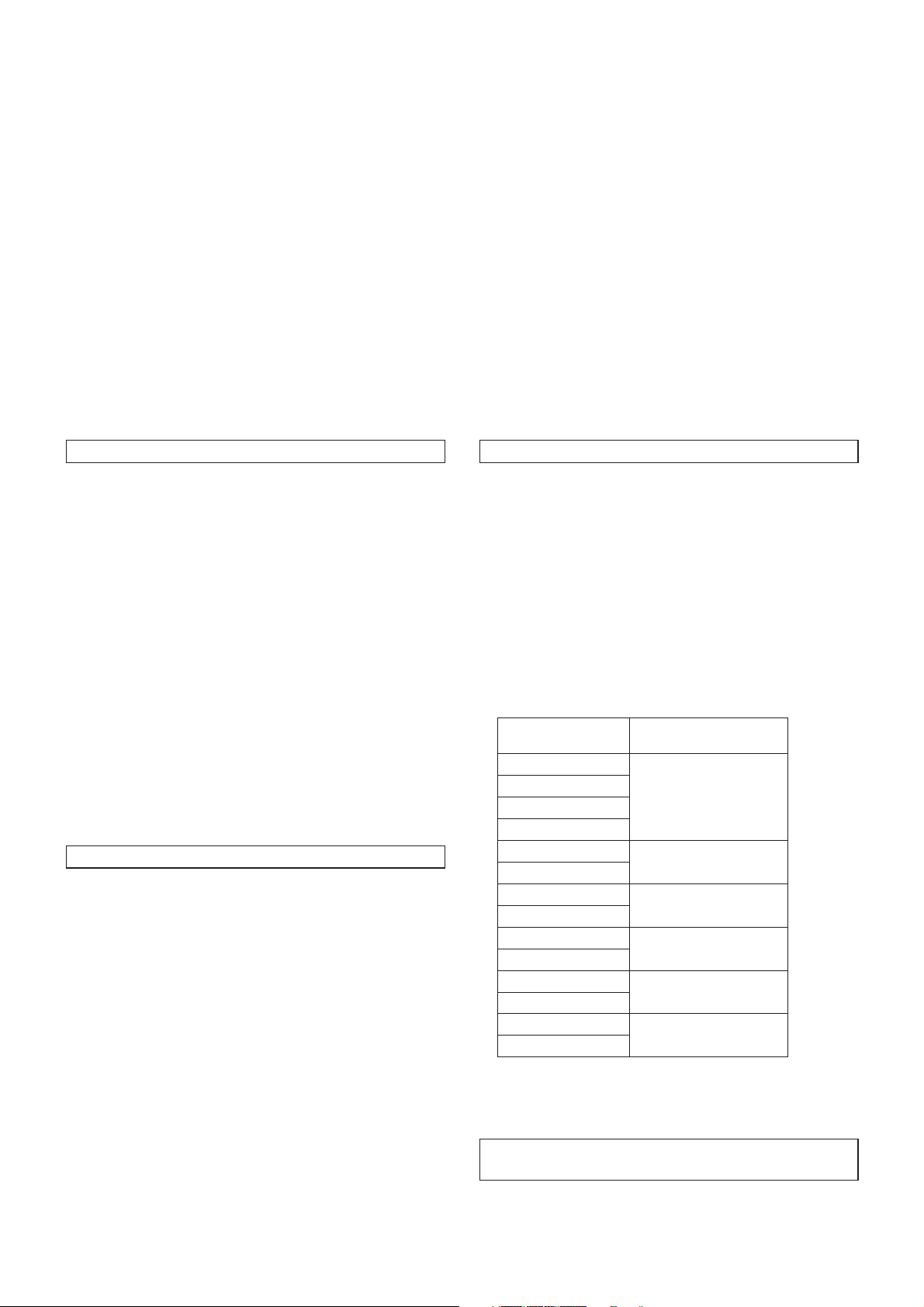
Required personal computer
environment
CPU Intel® CoreTM2 DUO 2.4 GHz or faster
recommended
Memory 512 MB or more
(When using Microsoft
1 GB or more, and when using
Microsoft
®
Windows® 7: 1 GB [32 bits]
or 2 GB [64 bits] or more)
Network
10Base-T or 100Base-TX port 1
function
Image display
Resolution: 1024 768 pixels or
function
Color generation: True Color 24 bits or
Supported
operating
system and
Web browser
Microsoft
SP1 64-bit*
Microsoft® Windows® 7 Professional
SP1 32-bit*
®
Windows® 7 Professional
1
1
Windows® Internet Explorer® 8.0*
Windows® Internet Explorer® 9.0*
®
Windows Vista®:
more
more
2
2
Microsoft® Windows Vista® Business
SP2 32-bit
®
Windows
Microsoft
SP3*
Microsoft® Windows® XP Professional
Edition SP3*
Internet Explorer® 7.0
®
Windows® XP Home Edition
3
3
Microsoft® Internet Explorer® 6.0 SP3
*1: This cannot be used in the
Windows
®
*2: This cannot be used with the 64-bit
version of Internet Explorer
*3: The Microsoft
Professional x64 Edition is not
supported.
Other CD-ROM drive
(for using the Operating Instructions and
various software)
®
Adobe
Reader
(for browsing the Operating Instructions
on the CD-ROM)
XP compatibility mode.
®
8.0.
®
Windows® XP
®
4
Before use
(continued)
IMPORTANT
Failure to provide the required personal computer
environment may slow down the delineation of
the images on the screen, make it impossible for
the web browser to work and cause other kinds of
problems.
When using Microsoft® Windows Vista® or Microsoft®
Windows
Windows
environment that is required and on the precautions and
other items.
®
7, refer to the “Notes on Windows Vista® /
®
7” (page 90) for details on the personal computer
Disclaimer of warranty
IN NO EVENT SHALL Panasonic Corporation BE LIABLE
TO ANY PARTY OR ANY PERSON, EXCEPT FOR
REPLACEMENT OR REASONABLE MAINTENANCE OF
THE PRODUCT, FOR THE CASES, INCLUDING BUT NOT
LIMITED TO BELOW:
ANY DAMAGE AND LOSS, INCLUDING WITHOUT
LIMITATION, DIRECT OR INDIRECT, SPECIAL,
CONSEQUENTIAL OR EXEMPLARY, ARISING OUT
OF OR RELATING TO THE PRODUCT;
PERSONAL INJURY OR ANY DAMAGE CAUSED BY
INAPPROPRIATE USE OR NEGLIGENT OPERATION
OF THE USER;
UNAUTHORIZED DISASSEMBLE, REPAIR OR
MODIFICATION OF THE PRODUCT BY THE USER;
INCONVENIENCE OR ANY LOSS ARISING WHEN
IMAGES ARE NOT DISPLAYED, DUE TO ANY
REASON OR CAUSE INCLUDING ANY FAILURE OR
PROBLEM OF THE PRODUCT;
ANY PROBLEM, CONSEQUENTIAL
INCONVENIENCE, OR LOSS OR DAMAGE, ARISING
OUT OF THE SYSTEM COMBINED BY THE DEVICES
OF THIRD PARTY;
LOSS OF REGISTERED DATA CAUSED BY ANY
FAILURE.
Network security
As you will use this unit connected to a network, your
attention is called to the following security risks.
Leakage or theft of information through this unit
Use of this unit for illegal operations by persons with
malicious intent
Interference with or stoppage of this unit by persons
with malicious intent
It is your responsibility to take precautions such as those
described below to protect yourself against the above
network security risks.
Use this unit in a network secured by a firewall, etc.
If this unit is connected to a network that includes PCs,
make sure that the system is not infected by computer
viruses or other malicious entities (using a regularly
updated antivirus program, anti-spyware program, etc.).
Protect your network against unauthorized access by
restricting users to those who log in with an authorized
user name and password.
Take measures by authenticating the users of the unit in
order to restrict access, for example, so that the setting
information contained inside the unit is not leaked over the
network.
Do not install the camera in locations where the camera or
the cables can be destroyed or damaged by persons with
malicious intent.
Refrain from connections that use public lines.
Usage restrictions
Use of the same segment is recommended for the network
in which the unit and the controller or personal computer are
connected.
If the equipment uses connections with different segments,
events based on the settings inherent to the network
equipment, for instance, may occur so check this thoroughly
prior to operation.
Before use
5

Basic shooting operations
1 Set the subject brightness to the appropriate
level.
2 Turn on the power of all the units and devices
in the system.
3 Select the unit to be operated.
Even when using only one unit, it must still be selected
from the wireless remote control or controller.
4 Select the shooting mode.
One of four shooting modes (Scene1, Scene2, Scene3
or Scene4) — whichever one will best suit the shooting
conditions — can be selected.
The shooting modes are set by the user.
For details of the factory settings, refer to pages 53 to 54.
Select the mode that satisfies the shooting conditions
and suits your preferences.
When continuing to shoot in the same circumstances,
there is no need to select another mode.
If the settings have already been changed and the original
settings are to be restored, refer to the “What to do when
encountering problems in the basic shooting operations”
(page 13) and “Camera screen” (page 38) in
“Setting the camera menu items”.
5 Start shooting.
(After shooting, turn off the power of all the
units and devices in the system.)
Note
Some of the initial settings are auto settings and
cannot be operated manually. To perform manual
operations for these settings, switch the auto
settings to manual settings as necessary.
6

How to turn the power on and off
Turning the power on
When performing the operations
using the wireless remote control
1 Set all the power switches of the units and
devices connected in the system to ON.
This unit does not have a power switch.
When power is supplied to it, the status display lamp
will light up orange, and the unit is set to the standby
mode.
2 Press one of the [CAM1] to [CAM4] buttons on
the wireless remote control to select the unit.
3 Press the [ON/STANDBY] button on the
wireless remote control for 2 seconds.
The POWER ON mode is established, images are
output, and control can be exercised.
The unit’s status display lamp now lights up green.
Notes
It takes maximum 30 seconds per unit for the initial
settings operation to be completed.
During this period, the unit cannot be operated.
(Status display lamp: light up orange)
When operation is transferred to the STANDBY
mode: The current zoom, focus and iris positions
are stored in the memory (POWER ON preset).
When operation is transferred to the POWER ON
mode: The zoom, focus and iris are adjusted to
the positions which were stored in the memory
(POWER ON preset) when operation was
transferred to the STANDBY mode.
4 If a multiple number of units are going to be
used, repeat steps
2 and 3 as required.
When performing the operations using the controller
When the AW-RP655 or AW-RP555 is connected:
1 Set all the power switches of the units and
devices connected in the system to ON.
This unit does not have a power switch.
When power is supplied to it, the status display lamp
will light up orange, and the unit is set to the standby
mode.
2 Set the [OPERATE] switch on the controller to
ON.
The POWER ON mode is established, images are
output, and control can be exercised.
The unit’s status display lamp now lights up green.
Notes
It takes maximum 30 seconds per unit for the initial
settings operation to be completed.
During this period, the unit cannot be operated.
(Status display lamp: light up orange)
When operation is transferred to the STANDBY
mode: The current zoom, focus and iris positions
are stored in the memory (POWER ON preset).
When operation is transferred to the POWER ON
mode: The zoom, focus and iris are adjusted to
the positions which were stored in the memory
(POWER ON preset) when operation was
transferred to the STANDBY mode.
Before setting the [OPERATE] switch on the controller to ON,
be absolutely sure to set all the power switches of the units
and devices connected in the system to ON.
For further details, refer to the Operating Instructions of the
controller.
Shooting
The unit’s status display lamp blinks green when a signal
matched by the remote control ID has been received, and
it blinks orange when a signal that is not matched by the
remote control ID has been received.
When the AW-RP50 is connected:
Refer to the Operating Instructions of the controller.
7

How to turn the power on and off
Turning the power off
(continued)
When performing the operations
using the wireless remote control
1 Press one of the [CAM1] to [CAM4] buttons on
the wireless remote control to select the unit.
2 Press the [ON/STANDBY] button on the
wireless remote control for 2 seconds.
The unit is set to the standby mode.
The unit’s status display lamp now lights up orange.
3 If a multiple number of units are going to be
used, repeat steps
1 and 2 as required.
4 Set all the power switches of the units and
devices connected in the system to OFF.
This unit does not have a power switch.
Notes
When operation is transferred to the STANDBY
mode: The current zoom, focus and iris positions
are stored in the memory (POWER ON preset).
When operation is transferred to the POWER ON
mode: The zoom, focus and iris are adjusted to
the positions which were stored in the memory
(POWER ON preset) when operation was
transferred to the STANDBY mode.
When performing the operations using the controller
When the AW-RP655 or AW-RP555 is connected:
1 Set the [OPERATE] switch on the controller to
OFF.
All the cameras (including the unit) connected to the
controller are set to the standby mode.
The unit’s status display lamp now lights up orange.
2 Set all the power switches of the units and
devices connected in the system to OFF.
This unit does not have a power switch.
Notes
When operation is transferred to the STANDBY
mode: The current zoom, focus and iris positions
are stored in the memory (POWER ON preset).
When operation is transferred to the POWER ON
mode: The zoom, focus and iris are adjusted to
the positions which were stored in the memory
(POWER ON preset) when operation was
transferred to the STANDBY mode.
For further details, refer to the Operating Instructions of the
controller.
When the AW-RP50 is connected:
Refer to the Operating Instructions of the controller.
8

Selecting the units
Up to four units can be operated using one wireless remote
control.
Up to five units and devices can be operated using one
controller.
Select the unit (or units) to be operated from the wireless
remote control or controller.
Even when using only one unit, it must still be selected.
When performing the operations
using the wireless remote control
To select the unit using the wireless remote control, the IR ID
switches on the unit’s back panel must be set.
For details of the IR ID switch settings, refer to pages 36 and 39
in the <Basics>.
1 Press the [CAM1], [CAM2], [CAM3] or [CAM4]
button.
The unit’s status display lamp blinks green when a signal
matched by the remote control ID has been received,
and it blinks orange when a signal that is not matched by
the remote control ID has been received.
When performing the operations using the controller
When the AW-RP655 is connected:
1 Press the [1], [2], [3], [4] or [5] button of
[CONTROL/PREVIEW MONITOR OUT SEL].
When the AW-RP555 is connected:
1 Press the [1], [2], [3], [4] or [5] button of
[CONTROL].
Shooting
When the AW-RP50 is connected:
Refer to the Operating Instructions of the controller.
Selecting the shooting modes (scene files)
Types of shooting modes
One of four shooting modes (Scene1, Scene2, Scene3
or Scene4) — whichever one will best suit the shooting
conditions — can be selected.
The shooting modes are set by the user.
For details of the factory settings, refer to pages 53 to 54.
Select the mode that satisfies the shooting conditions and
suits your preferences.
The settings can be changed by menu operations.
The results of the white balance and other adjustments
are stored in the memory separately by shooting mode.
Be absolutely sure to select the shooting mode before
making any adjustments.
Note
Some of the initial settings are auto settings and
cannot be operated manually. To perform manual
operations for these settings, switch the auto
settings to manual settings as necessary.
Scene1
Scene2
Scene3
Scene4
The settings of your preferences can be established
in line with the shooting scene, lighting and other
conditions.
9
Selecting the shooting modes (scene files)
How to select the shooting mode
When performing the operations
using the wireless remote control
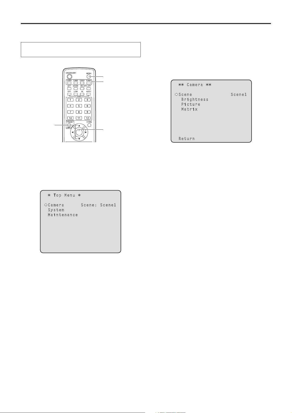
4 Press the [] button.
2, 8
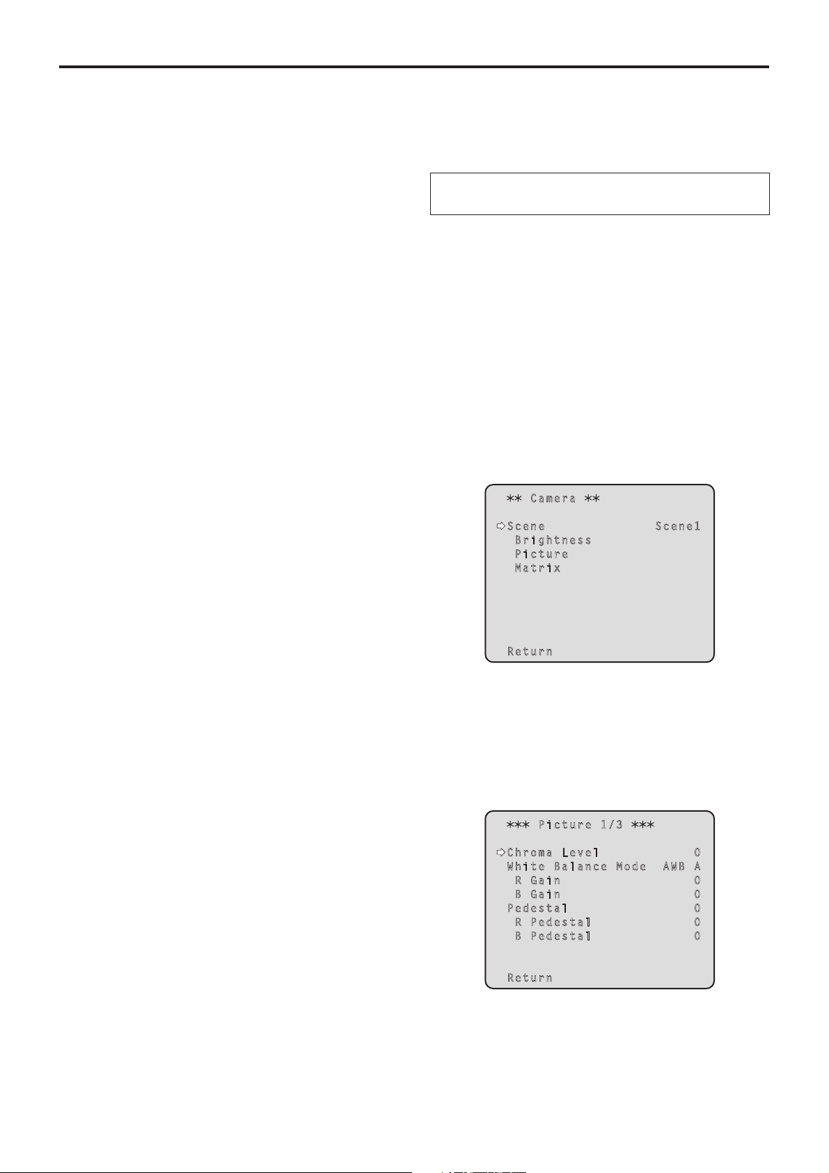
1
The “Camera” sub-menu is displayed on the monitor.
Camera
Scene Scene1
Brightness
Picture
Matrix
(continued)
3, 5, 7
4, 6, 7
1 Press the [CAM1], [CAM2], [CAM3] or [CAM4]
button to select the unit.
2 Press the [MENU] button for 2 seconds.
The Top Menu is displayed.
Top Menu
Camera Scene: Scene1
System
Maintenance
Return
5 Press the [] or [] button to bring the cursor
to “Scene”.
6 Press the [] button.
The shooting mode blinks.
7 Press the [] or [] button to select the
shooting mode (Scene1, Scene2, Scene3 or
Scene4) to be used, and press the [] button to
enter the selection.
8 Press the [MENU] button for 2 seconds.
The camera menu display is exited.
3 Press the [] or [] button to bring the cursor
to “Camera”.
10

Selecting the shooting modes (scene files)
When performing the operations using the controller
(continued)
When the AW-RP655 is connected:
1 Press one of the [1] to [5] buttons of
[CONTROL/PREVIEW MONITOR OUT SEL] to
select the unit which is to be operated.
2 Press the [MENU] button to set the LCD panel
display to the menu mode.
3 Turn the jog dial (main) until CAMERA SETTING
appears, and press the [OK] button.
CAMERA SETTING
OK Key
4 When the scene selection menu has appeared
on the LCD panel, select the scene to be set,
and press the [OK] button.
SCENE HALOGEN
OK Key
When the AW-RP555 is connected:
1 Press the [1], [2], [3], [4] or [5] button of
[CONTROL] to select the unit.
2 Press the [1], [2], [3] or [USER] button of
[SCENE FILE] to select the shooting mode.
Shooting mode [SCENE FILE] button
Scene1 [1]
Scene2 [2]
Scene3 [3]
Scene4 [USER]
Shooting
When the AW-RP50 is connected:
Refer to the Operating Instructions of the controller.
The scene names displayed on the LCD panel correlate
with the scene files of the AW-HE120 as shown below.
AW-RP655 display AW-HE120 scene file
HALOGEN Scene1
FLUORESCENT Scene2
OUTDOOR Scene3
USER Scene4
5 When the following message appears on the
LCD panel, press the [MENU] button twice to
exit the menu mode.
OPEN CAMERA MENU ?
OK Key
11
Shooting
When performing the operations
using the wireless remote control
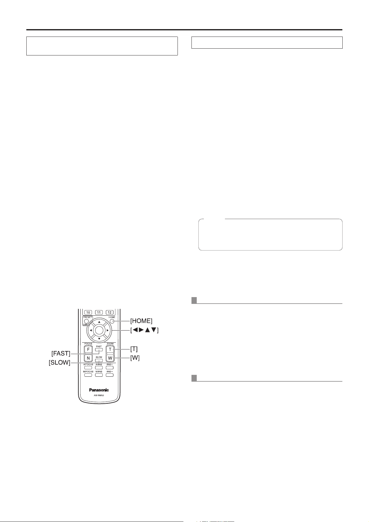
Changing the camera’s direction
Moving the camera toward the left or right (panning):
Press the [] or [] button.
Moving the camera up or down (tilting):
Press the [] or [] button.
Moving the camera diagonally:
Press the [] or [] button and [] or [] button at
the same time.
Returning the camera to the reference position:
Press the [HOME] button for 2 seconds.
Using the zoom function
Zooming in (the subject becomes magnified in size):
Press the [T] button of [ZOOM].
Zooming out (the subject becomes reduced in size):
Press the [W] button of [ZOOM].
Switching the panning/tilting and lens
operation speed
Changing the direction or zoom at high speed:
Press the [FAST] button.
When performing the operations using the controller
Changing the camera’s direction
Moving the camera toward the left or right (panning):
Tilt the [PAN/TILT] lever toward L or R.
Moving the camera up or down (tilting):
Tilt the [PAN/TILT] lever toward UP or DOWN.
Moving the camera diagonally:
Tilt the [PAN/TILT] lever diagonally.
Returning the camera to the reference position:
If the controller has a [HOME] button, press the
[HOME] button.
Using the zoom function
Zooming in (the subject becomes magnified in size):
Tilt the [ZOOM] lever toward the TELE direction.
Zooming out (the subject becomes reduced in size):
Tilt the [ZOOM] lever toward the WIDE direction.
Note
The indicator displays of the AW-RP655 are
indicators that show the positions of the optical
zoom. They will not work for electronic zooming.
Changing the direction or zoom at low speed:
Press the [SLOW] button.
The speeds at which the pan, tilt, zoom focus and iris are
controlled are now switched.
Switching the panning/tilting and lens
operation speed
AW-RP655 and AW-RP555
1 Press the [SPEED] button.
Each time the [SPEED] button is pressed, the control
speed is switched between the high speed (the button’s
lamp is off) and low speed (the button’s lamp is lit).
The speeds at which the pan, tilt, zoom focus and iris are
controlled are now switched.
AW-RP50
Refer to the Operating Instructions of the controller.
12

What to do when encountering problems in the basic shooting operations
If the trouble is not resolved by taking the action suggested
below, refer to “Troubleshooting” (page 42 in the <Basics>).
When performing the operations
using the wireless remote control
The unit does not move.
Press the [CAM1], [CAM2], [CAM3] or [CAM4] button to
select the unit which is to be operated.
If only one unit is being used, it is normally selected using
the [CAM1] button.
Check that the IR ID switches have been set correctly.
(Refer to pages 36 and 39 in the <Basics>.)
If the unit’s status display lamp is off or lights up orange, it
means that the unit’s power is not on.
Refer to “Turning the power on” (page 7), and turn on the
power.
If the unit’s status display lamp does not blink even when
the wireless remote control is operated near the unit’s
wireless remote control signal light-sensing area, it means
that the wireless remote control’s batteries have run down.
Replace the batteries.
Multiple color bands (color bars) are displayed.
Press the [MODE] button to switch to the camera picture.
When performing the operations using the controller
The unit does not move.
Select the unit to be operated by following the procedure
below.
When the AW-RP655 is connected:
Press the [1], [2], [3], [4] or [5] button of [CONTROL/
PREVIEW MONITOR OUT SEL].
When the AW-RP555 is connected:
Press the [1], [2], [3], [4] or [5] button of [CONTROL].
When the AW-RP50 is connected:
Refer to the Operating Instructions of the controller.
If the [OPERATE] lamp on the controller is off, it means
that the power of the controller is not on.
If the unit’s status display lamp is off or lights up orange, it
means that the unit’s power is not on.
Refer to “Turning the power on” (page 7), and turn on the
power.
Shooting
The menu screen is displayed.
Press the [MENU] button for 2 seconds to exit the camera
menu.
The lens focus is not adjusted automatically.
Press the [A/FOCUS] button to switch to auto focusing.
The camera picture is too light or too dark.
1. Press the [A/IRIS] button to switch automatically to the
lens iris adjustment.
2. Press the [AUTO] button of [GAIN] to switch automatically
to the gain adjustment.
Something is wrong with the coloring of the
camera pictures.
Refer to “Auto tracking white adjustment (ATW)” (page 24), and
switch to “ATW”.
The camera menus are not displayed.
If any of the camera menus are displayed within less than
a minute after the camera was restarted, the menus will be
displayed in all the outputs.
Check “OSD Mix” (page 50) on the camera menu Other 3/3
screen.
Multiple color bands (color bars) are displayed.
Press the [MODE] button to switch to the camera picture.
The menu screen is displayed.
Press the [MENU] button to exit the camera menu.
The lens focus is not adjusted automatically.
Press the [EXT(AF)] button to switch to auto focusing.
The camera picture is too light or too dark.
1. Press the [IRIS] button several times to turn on its lamp,
and switch the lens iris adjustment to auto.
2. Press the [GAIN] button several times to turn on its lamp,
and switch the gain adjustment to auto.
Something is wrong with the coloring of the
camera pictures.
Refer to “Auto tracking white adjustment (ATW)” (page 24), and
switch to “ATW”.
The camera menus are not displayed.
If any of the camera menus are displayed within less than
a minute after the camera was restarted, the menus will be
displayed in all the outputs.
Check “OSD Mix” (page 50) on the camera menu Other 3/3
screen.
13

More advanced operations
Manual shooting (see pages 15 to 18)
Manual adjustment of focus
Manual adjustment of iris
Manual adjustment of shutter speed
Manual adjustment of gain
Preset memories (see pages 19 to 21)
Up to 100 settings for the camera direction (panning and
tilting), zoom, focus, iris, gain up and white balance can be
registered in the preset memories, and called.
The number of settings that can be registered and
called depends on the type of wireless remote control
(12 settings) or controller that is used for operation.
White balance adjustment
(see pages 22 to 24)
This adjustment is performed to express the white
accurately. Its setting also has an effect on the color tones
of the entire screen.
It must be performed when using the unit for the first
time or when the unit has not been used for a prolonged
period.
It must be performed when the lighting conditions or
brightness has changed.
Once the white balance has been attained, no further
adjustment is required provided that the unit is going to be
used under the same conditions.
Black level (master pedestal) adjustment
(see pages 26 to 27)
This adjustment is performed to align the black level
(pedestal level) of a multiple number of cameras.
Ask your dealer to perform this adjustment.
Genlock adjustment (see page 28)
This adjustment is performed to achieve phase alignment
by applying external synchronization (genlock) when a
multiple number of cameras will be used or when the unit
will be used in combination with other devices.
Ask your dealer to perform this adjustment.
Black balance adjustment (see page 25)
This adjustment is performed to express the black
accurately. Its setting also has an effect on the color tones
of the entire screen.
It must be performed when using the unit for the first
time or when the unit has not been used for a prolonged
period.
It must be performed when the ambient temperature has
changed significantly and at the change of the seasons.
Once the black balance has been attained, no further
adjustment is required provided that the unit is going to be
used under the same conditions.
14

Manual shooting
Manually adjusting the focus
The lens focus can be adjusted manually.
When the AW-RP555 is connected:
When performing the operations
using the wireless remote control
1 Press the [M/FOCUS] button to switch the
focus to manual adjustment.
2 Press the [F] or [N] button of [FOCUS], and
adjust the focus.
When the [F] button is pressed, the focus moves further
away (far); conversely, when the [N] button is pressed, it
moves nearer (near).
The speed of focusing and other adjustments can
be switched to fast or slow by pressing the [FAST] or
[SLOW] button, respectively.
3 If necessary, press the [A/FOCUS] button to
return the focus to the automatic adjustment.
When performing the operations using the controller
When the AW-RP655 is connected:
1 Press the [EXT(AF)] button to switch the focus
to manual adjustment.
1 Press the [EXT(AF)] button to switch the focus
to manual adjustment.
2 Adjust the focus manually by tilting the
[FOCUS] lever.
Furthermore, every time the [SPEED] button is pressed,
the speed of the focusing and other adjustments can be
switched to fast or slow.
3 If necessary, press the [EXT(AF)] button to
return the focus to the automatic adjustment.
When the AW-RP50 is connected:
Refer to the Operating Instructions of the controller.
Note
When the focus is set to manual, the subject may
go out of focus during panning, tilting and zooming.
Therefore, the unit comes with a function which
compensates for this. (Focus compensation during
zooming function: Focus ADJ With PTZ.)
This function was set to ON at the factory.
If the function has been set to OFF, either adjust the
focus, as required, after zooming or set the focus to
auto. (See page 49 and page 73.)
Shooting
2 Adjust the focus manually by turning the dial
above the lit [FOCUS] lamp whether it is the
lamp of the [PAN/TILT] lever or [ZOOM] lever.
Furthermore, every time the [SPEED] button is pressed,
the speed of the focusing and other adjustments can be
switched to fast or slow.
3 If necessary, press the [EXT(AF)] button to
return the focus to the automatic adjustment.
15

Manual shooting
(continued)
Manually adjusting the iris
The lens iris can be adjusted manually.
When the AW-RP555 is connected:
When performing the operations
using the wireless remote control
1 Press the [M/IRIS] button to switch the iris to
manual adjustment.
2 Adjust the iris using the [IRIS +] or [IRIS –]
button.
Press the [IRIS +] button to adjust the lens iris in the
opening direction; conversely, press the [IRIS –] button to
adjust the lens iris in the closing direction.
The speed of the iris and other adjustments can be
switched to fast or slow by pressing the [FAST] or
[SLOW] button, respectively.
3 If necessary, press the [A/IRIS] button to return
the iris to the automatic adjustment.
1 Press the [IRIS] button to turn off its lamp and
switch to manual adjustment.
2 Turn the [LEVEL] dial of [IRIS] to adjust the iris
manually.
The position of the [LEVEL] dial does not represent an
absolute value.
This is why the brightness may differ from one camera to
another even when the dial is set to the same position.
3 If necessary, press the [IRIS] button to turn on
its lamp and switch to automatic adjustment in
order to return the iris to automatic adjustment.
When the AW-RP50 is connected:
Refer to the Operating Instructions of the controller.
When performing the operations using the controller
When the AW-RP655 is connected:
1 Press the [IRIS] button several times to turn
off the button’s lamp and switch to manual
adjustment.
2 Adjust the iris manually by turning the dial
above the lit [IRIS] lamp whether it is the lamp
of the [PAN/TILT] lever or [ZOOM] lever.
3 If necessary, press the [IRIS] button several
times and turn on its lamp to return the iris to
the automatic adjustment.
16
Manual shooting
(continued)
Manually adjusting the shutter speed
The shutter speed can be set using two methods. One is
a method that specifies the time (where a time such as
1/250 sec. is designated), and the other is a method that
specifies the frequency (where synchro scan, 60.17 Hz, etc.
is designated).
When shooting a TV screen or PC monitor screen, the
horizontal noise generated when the screen is shot can
be minimized by adjusting the frequency to the screen
frequency using synchro scan.
When performing the operations
using the wireless remote control
How to set the shutter speed using the AW-RP555
1 With the [MEMORY] button still held down,
press the [SHUTTER] button.
The [PRESET] [1] to [5] and [6] to [10] buttons blink
alternately.
2 Press one of the [1] to [8] buttons or the
[10] [PRESET] button — whichever button
corresponds to the shutter speed which is to
be set.
Any of the shutter speeds in the table below can be set.
Perform the adjustments on the Camera menu.
For further details, refer to the [Shutter Mode] on page 38 and
[Step/Synchro] items on page 39.
When performing the operations using the controller
The procedure is the same as for “When performing the
operations using the wireless remote control” in “Basic
operations” (pages 29 to 36).
When the AW-RP555 is connected:
1 Press the [SHUTTER] button and turn its lamp
on.
The shutter speed set ahead of time is selected.
2 If necessary, press the [SHUTTER] button and
turn its lamp off in order to return the shutter to
the OFF setting.
[When 59.94 Hz has been set as the unit’s frequency]
OFF 1/59.94 [6] 1/4000
[1] 1/100 [7] 1/10000
[2] 1/250 [8] Synchro Scan
[3] 1/500 [9] ELC
[4] 1/1000 [10] OFF
[5] 1/2000
[When 50 Hz has been set as the unit’s frequency]
OFF 1/50 [6] 1/4000
[1] 1/120 [7] 1/10000
[2] 1/250 [8] Synchro Scan
[3] 1/500 [9] ELC
[4] 1/1000 [10] OFF
[5] 1/2000
Any change in the shutter speed is reflected the next
time the [SHUTTER] button is pressed and its lamp is
turned on.
When OFF is selected, the shutter will not operate
even when the [SHUTTER] button is pressed.
Select the synchro scan setting on the menu.
The shutter speed setting performed here is stored in
the memory even when the power of the AW-RP555
is turned off.
For further details, refer to the Operating Instructions of the
AW-RP555.
Shooting
17
Manual shooting
(continued)
Manually adjusting the gain
There are two ways to adjust the gain. One way involves
using the buttons on the wireless remote control or controller;
the other way involves using the Camera menu or Web
setting.
The gain can be adjusted more precisely using the Camera
menu or Web setting.
For further details, refer to the [Gain] item on page 39 and
page 64.
Note
When adjusting the gain, the light quantity may
change suddenly (causing the image output to be
subjected to a shock).
When performing the operations
using the wireless remote control
1 Press the [OFF], [LOW] or [HI] button.
These buttons enable the gain increase to be selected in
three steps.
[LOW] is used to select 9 dB; [HI] is used to select 18 dB.
When the AW-RP555 is connected:
1 Press the [GAIN] button to turn off its lamp.
Each time this button is pressed, one of the three gain
increase amounts can be selected in sequence.
The current status is displayed as follows.
[MANU]
[L] lamp
0 dB Off Off Off
LOW Lit Off Off
HIGH Off Lit Off
AUTO Off Off Lit
Other Lit Lit Off
[MANU]
[H] lamp
[GAIN]
button
2 If necessary, press the [GAIN] button several
times and turn on its lamp in order to return the
gain to the automatic adjustment (AGC).
2 If necessary, press the [AUTO] button in order
to return the gain to the automatic adjustment
(AGC).
When performing the operations using the controller
When the AW-RP655 is connected:
1 Press the [GAIN] button to turn off its lamp, and
then switch to manual adjustment.
The preset gain increase amount is now selected.
For further details on the gain increase amount setting,
refer to the Operating Instructions of the AW-RP655.
2 If necessary, press the [GAIN] button and turn
on its lamp in order to return the gain to the
automatic adjustment (AGC).
When the AW-RP50 is connected:
Refer to the Operating Instructions of the controller.
In any case, the maximum gain of the automatic adjustment
can be set by the camera menu or Web setting.
For further details, refer to the [AGC Max Gain] item on
page 39 and page 64.
18

Preset memories
This unit enables up to 100 settings for the camera direction
(panning and tilting), zoom, focus, iris, gain and white
balance to be registered in its preset memories, and called.
However, the number of settings that can be registered and
called depends on the type of wireless remote control or
controller that is used for operation.
The focus and iris operating modes (manual and auto
settings) are neither registered nor recalled.
The current focus and iris values are registered.
The focus and iris values can be recalled only when the
manual settings are applicable.
For the white balance, the current White Balance Mode
adjustment values are registered. If a preset value
is recalled when AWB A or AWB B is selected, the
adjustment value selected when it was registered as a
preset will be recalled.
The White Balance Mode (ATW, AWB A or AWB B)
stored using the AW-RP655 are recalled only when the
AW-RP655 is connected.
Notes
When there is a large difference in the environmental
temperature between the time of registration and the
time the setting is called, displacement of the preset
position may occur.
If displacement occurs, perform registration again.
When a manual operation is performed for pan, tilt,
zoom, focus or iris during preset recall, the preset
operation for the pan, tilt, zoom, focus or iris operation
concerned will be aborted.
If another preset has been recalled during an ongoing
preset recall, the preset being recalled is aborted,
and operation for the preset called last is performed
instead.
When performing the operations
using the wireless remote control
Twelve settings (preset No.1 to No.12) can be registered and
called using the wireless remote control.
The [1] to [12] buttons correspond to the unit’s preset
memories No.1 to No.12.
Registering the settings in the preset memories
1 Display the picture to be shot on the monitor.
Operate the pan, tilt or zoom buttons to determine the
camera angle.
Adjust the focus, iris, gain and white balance if they need
to be adjusted.
2 While holding down the [PRESET] button, press
the button corresponding to the preset memory
number.
If a preset memory number with an already registered
setting has been selected, the existing setting will be
erased and replaced with the new one.
Calling the settings of the preset memories
1 Press the button in which the preset memory
setting has been registered.
Adjustment
19

Preset memories
(continued)
When performing the operations using the controller
When the AW-RP655 is connected:
Up to 50 settings can be registered and called.
The [1] to [50] buttons of [TRACING/PRESET MEMORY]
correspond to the unit’s preset memories No.1 to No.50.
Registering the settings in the preset memories
1 Set to the preset memory mode.
Press the [TR/PSET] button to turn off its lamp.
2 Set to the memory recording mode.
Press the [M.LOCK] button to turn off its lamp.
3 Display the picture to be shot on the monitor.
Operate the [PAN/TILT] lever and [ZOOM] lever to
determine the camera angle.
Adjust the focus, iris, gain and white balance if they need
to be adjusted.
4 Hold down the [MEMORY] button.
The buttons among the [1] to [50] buttons of [TRACING/
PRESET MEMORY] in which settings can be registered
now start blinking in sequence.
Preset memory settings cannot be registered in
buttons whose lamps are off (since they contain
tracing memory settings).
5 With the [MEMORY] button still held down,
press the button of the preset memory number
in which the setting is to be registered.
Calling the settings of the preset memories
1 Set to the preset memory mode.
Press the [TR/PSET] button to turn off its lamp.
2 Press the button among the [1] to [50] buttons
of [TRACING/PRESET MEMORY] in which the
desired setting was registered.
Erasing preset memory settings
1 Set to the preset memory mode.
Press the [TR/PSET] button to turn off its lamp.
2 Set the memory recording mode.
Press the [M.LOCK] button to turn off its lamp.
3 Hold down the [RESET] button.
The buttons among the [1] to [50] buttons of [TRACING/
PRESET MEMORY] whose settings can be erased now
start blinking in sequence.
The settings for the buttons whose lamps are off
cannot be erased (since they contain tracing memory
settings).
4 With the [RESET] button still held down, press
the button of the preset memory number whose
setting is to be erased.
20

Preset memories
(continued)
When the AW-RP555 is connected:
Up to 10 settings can be registered and called.
The [1] to [10] buttons of [PRESET] correspond to the unit’s
preset memories No.1 to No.10.
Registering the settings in the preset memories
1 Display the picture to be shot on the monitor.
Operate the [PAN/TILT] lever and [ZOOM] lever to
determine the camera angle.
Adjust the focus, iris, gain and white balance if they need
to be adjusted.
2 Hold down the [MEMORY] button.
The buttons among the [1] to [10] buttons of [PRESET]
in which settings can be registered now start blinking in
sequence.
3 With the [MEMORY] button still held down,
press the button of the preset memory number
in which the setting is to be registered.
When the AW-RP50 is connected:
Up to 100 settings can be registered and called.
For details, refer to the Operating Instructions of the
controller.
Adjustment
Calling the settings of the preset memories
1 Press the button among the [1] to [10] buttons
of [PRESET] in which the desired setting was
registered.
Erasing preset memory settings
1 While holding down the [MEMORY] button,
press the [OP] button.
The [OP] button lamp blinks, and the standby status is
established.
2 Press the [OP] button to establish the setting
mode.
The [PRESET] [1] to [10] button lamps blink in sequence.
When the [ZOOM] lever, [PAN/TILT] lever or [FOCUS]
lever is now operated, the mode is forcibly exited.
3 Press the [PRESET] button corresponding to
the preset memory which is to be deleted.
21
White balance adjustment
White balance adjustment
In order for the white to be reproduced accurately, the ratio
between the three primary colors (RGB) is adjusted. If the
white balance has shifted out of adjustment, not only will the
white be reproduced poorly but the color tones of the entire
screen will also be degraded.
This adjustment must be performed when using the
unit for the first time or when the unit has not been
used for a prolonged period.
It must be performed when the lighting conditions or
brightness has changed.
Either AWB (automatic white balance adjustment) which
initiates automatic adjustment when the AWB button on the
controller has been pressed or ATW (automatic tracking
white balance adjustment) which constantly adjusts the white
balance can be selected for adjustment purposes.
The results of the AWB adjustment can be stored in two
memories, A and B, when “AWB A” or “AWB B” has been
selected for the white balance.
Once the white balance values have been adjusted, their
setup procedure will be completed simply by selecting
them using the camera menus or web settings, or by
pressing the buttons on the controller, provided that they
are going to be used under the same conditions as the
ones established when the values were set.
There is no need to set it again.
Once a new setting is entered, the previous setting will be
erased.
Automatic adjustment
(AWB: AWB A or AWB B)
1 Shoot a white subject (such as a white wall or
handkerchief) so that it fills the screen.
Steps
the “AWB A” or “AWB B” memory. They need not be taken
if a selection has already been made.
2 Select Scene1, Scene2, Scene3 or Scene4 as
the shooting mode by following the procedure
in “Selecting the shooting modes (scene files)”
(page 10).
When performing the operations
using the wireless remote control
Do not shoot shiny or very bright objects.
2 through 8 represent the procedure for selecting
Camera
Scene Scene1
Brightness
Picture
Matrix
Use the two memories to store settings corresponding to
different shooting conditions.
Return
3 Press the [] or [] button to bring the cursor
to “Picture”.
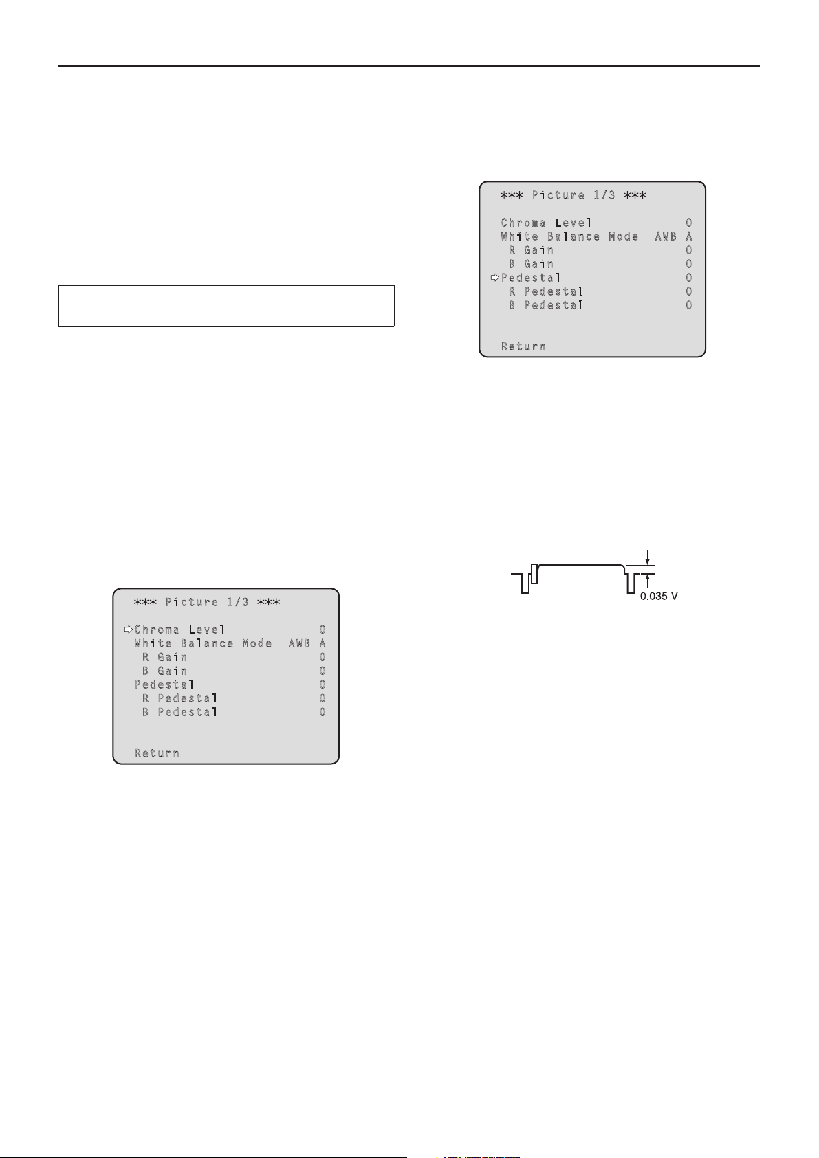
4 Press the [] button.
The “Picture 1/3” sub-menu is displayed.
Picture 1/3
Chroma Level 0
White Balance Mode AWB A
R Gain 0
B Gain 0
Pedestal 0
R Pedestal 0
B Pedestal 0
Return
22
White balance adjustment
(continued)
5 Press the [] or [] button to bring the cursor
to “White Balance Mode”.
6 Press the [] button.
“White Balance Mode” starts blinking.
7 Press the [] or [] button to change the
White Balance Mode to be used to “AWB A” or
“AWB B”, and press the [] button to enter the
selection.
8 Press the [MENU] button for 2 seconds.
The camera menu display is exited.
9 Press the [SET] button for 2 seconds.
The auto white balance adjustment (AWB) and auto
black balance adjustment (ABB) are performed, and the
white balance setting is entered.
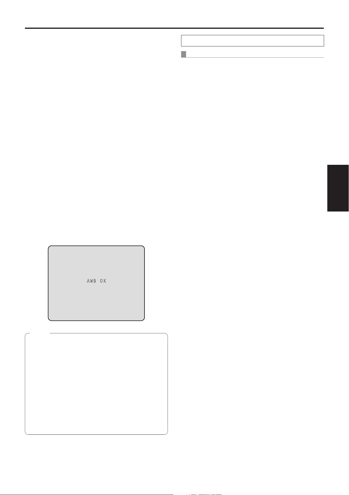
When “On” has been selected as the “OSD Status”
(page 50) setting, the “AWB OK” message will appear
at the center of the screen when the white balance
adjustment is completed successfully.
When the black balance adjustment is completed
successfully, the “ABB OK” message appears at the
center of the screen.
When performing the operations using the controller
When the AW-RP655 or AW-RP555 is connected:
1 Shoot a white subject (such as a white wall or
handkerchief) so that it fills the screen.
Do not shoot shiny or very bright objects.
2 Press the [A] button or [B] button of [WHITE
BAL] to select “AWB A” or “AWB B” for the
white balance.
The selected button’s lamp lights.
The white balance setting is not entered if “ATW” has
been selected.
3 Press the [AWC] button.
The auto white balance adjustment (AWB) is executed,
and the white balance setting is entered.
The [AWC] button’s lamp blinks while the white balance
is being adjusted, and its lamp goes off when the
adjustment is completed successfully. Its lamp lights if
the white balance could not be adjusted.
If color bars have been selected (the [MODE] button
or [BAR/CAM] button’s lamp lights) or if ATW is
selected (the [ATW] button’s lamp lights), it means
that the [AWC] button is not working or that the auto
white balance adjustment has failed. (The button’s
lamp lights.)
Adjustment
AWB OK
Notes
The black balance is set at the same time.
When this takes place, the lens is closed and then the
adjustment is performed so the screen will temporarily
turn black.
When only the auto white balance adjustment (AWB)
is to be performed, ensure that the [SET] button is
pressed or held down for a period of time which does
not exceed 2 seconds.
The white balance cannot be adjusted when color bars
are displayed. Press the [MODE] button to switch to
the camera picture.
When the adjustment has failed, an error message
such as “OUT RANGE NG”, “HIGH LIGHT NG”,
“LOW LIGHT NG” or “ATW NG” is displayed.
23

White balance adjustment
(continued)
When the AW-RP50 is connected:
Refer to the Operating Instructions of the controller.
Notes
White balance may not be correctly set if the lighting
of the object is too weak.
Since the unit has a built-in memory, the set white
balance will remain in the memory even if power is
turned off. Therefore, it is not necessary to reset the
white balance if the color temperature of those objects
remains unchanged. However, it must be reset if the
color temperature changes, such as when you move
from indoors to outside, or vice versa.
Auto tracking white adjustment (ATW)
When the white balance adjustment is set to “ATW”, the
white balance continues to be adjusted automatically all
the time, and it is automatically corrected even when the
light source or color temperature has changed to produce
completely natural pictures.
3200K and 5600K presets
When “3200K” or “5600K” is selected for the white balance,
the white balance is set using a color temperature of
3200K (equivalent to halogen light) or 5600K (equivalent to
daylight), respectively.
This function works when “3200K” or “5600K” is selected
instead of “AWB A” or “AWB B” by following the steps for
“Automatic adjustment” in “White balance adjustment”
(page 22).
(From the controller, this operation can be performed
only using the menu displays. Refer to “Basic operations”
(page 29).)
This function works when “ATW” is selected instead of
“AWB A” or “AWB B” by following the steps for “Automatic
adjustment” in “White balance adjustment” (page 22).
Notes
ATW might not function properly when high brightness
light (ex. fluorescent lamp) beams into a screen.
White balance may not be accurately set if there is no
white object in the scene being shot.
The white balance may shift out of adjustment when
a different kind of light source such as sunlight or
fluorescent lighting applies.
24

Black balance adjustment
Black balance adjustment
In order for the black to be reproduced accurately, the zero
levels of the three primary colors (RGB) are adjusted. If the
black balance has shifted out of adjustment, not only will the
black be reproduced poorly but the color tones of the entire
screen will also be degraded.
Normally, the black balance need not be re-adjusted, but it is
necessary in the following situations.
This adjustment must be performed when using the
unit for the first time or when the unit has not been
used for a prolonged period.
The adjustment must be performed when the ambient
temperature has changed significantly and at the
change of the seasons.
When performing the operations using the controller
When the AW-RP655 or AW-RP555 is connected:
1 Press the [ABC] button.
The auto black balance operation is executed, and the
black balance setting is entered.
The [ABC] button’s lamp or LED blinks while the black
balance is being adjusted, and its lamp goes off when
the adjustment is completed successfully. It lights if the
black balance could not be adjusted.
If color bars have been selected (the [MODE] button
or [BAR/CAM] button lights), it means that the [ABC]
button is not working or that the auto black balance
adjustment has failed. (The button’s lamp lights.)
Automatic adjustment
When performing the operations
using the wireless remote control
The procedure is the same as with “Automatic adjustment” in
“White balance adjustment” (page 22).
The auto white balance adjustment (AWB) and auto black
balance adjustment (ABB) can be performed, and the black
balance setting entered.
The white balance setting is also entered at the same
time so ensure that the conditions for adjusting the white
balance are met before proceeding.
The black balance cannot be adjusted when color bars
are displayed. Press the [MODE] button to switch to the
camera picture.
When the AW-RP50 is connected:
Refer to the Operating Instructions of the controller.
Adjustment
25
Black level (master pedestal) adjustment
Black level (master pedestal) adjustment
The black level can be adjusted when using a multiple
number of cameras including the unit. Ask your dealer to
perform this adjustment.
(Use an oscilloscope or waveform monitor for the
adjustment.)
Adjust the black level in accordance with the units and
devices used.
When performing the operations
using the wireless remote control
5 Press the [] or [] button to bring the cursor
to “Pedestal”.
Picture 1/3
Chroma Level 0
White Balance Mode AWB A
R Gain 0
B Gain 0
Pedestal 0
R Pedestal 0
B Pedestal 0
1 Press the [M/IRIS] button.
Set the iris to the manual mode.
2 Press the [IRIS –] button.
The lens iris is stopped down.
3 Press the [] or [] button to bring the cursor
to “Picture”.
4 Press the [] button.
The “Picture 1/3” sub-menu is displayed.
Picture 1/3
Chroma Level 0
White Balance Mode AWB A
R Gain 0
B Gain 0
Pedestal 0
R Pedestal 0
B Pedestal 0
Return
6 Press the [] button to start the “Pedestal”
value blinking.
7 Press the [] or [] button, change the
“Pedestal” value, and press the [] button to
enter the selection.
Adjust the black level to a value of approx. 0.035 V.
The pedestal values can be adjusted finely using the
“R Pedestal” and “B Pedestal” settings.
8 Press the [MENU] button for 2 seconds.
The camera menu display is exited.
26
Return
9 If necessary, press the [A/IRIS] button to adjust
the iris automatically.

Black level (master pedestal) adjustment
When performing the operations using the controller
(continued)
When the AW-RP655 is connected:
1 Press the [IRIS] button several times to turn off
its lamp.
Set the iris to the manual ([MANU]) mode.
2 Turn the [FOCUS/IRIS] dial to stop down the
lens iris.
3 Press the [R/B GAIN/PED] button several
times so that the “PEDESTAL TOTAL” item is
displayed on the LCD panel.
4 Turn the jog dial (main) and adjust the black
level to 0.035 V.
5 If necessary, adjust the iris automatically.
Press the [IRIS] button several times to turn on its
lamp.
When the AW-RP555 is connected:
1 Press the [IRIS] button several times to turn off
its lamp.
Set the iris to the manual ([MANU]) mode.
2 Turn the [LEVEL] dial of [IRIS] to stop down the
lens iris.
3 Follow the operation steps in “Basic
operations” (page 35), and use the camera
menu to perform the adjustment.
When the AW-RP50 is connected:
Refer to the Operating Instructions of the controller.
Adjustment
27
Genlock adjustment
Genlock adjustment
The genlock adjustment is performed to achieve phase
alignment by applying external synchronization (genlock)
when a multiple number of cameras will be used or when the
unit will be used in combination with other devices.
This unit supports BBS (Black Burst Sync) and tri-level sync
external synchronization signals.
Ask your dealer to perform this adjustment.
(Use a dual-trace oscilloscope for the adjustment.)
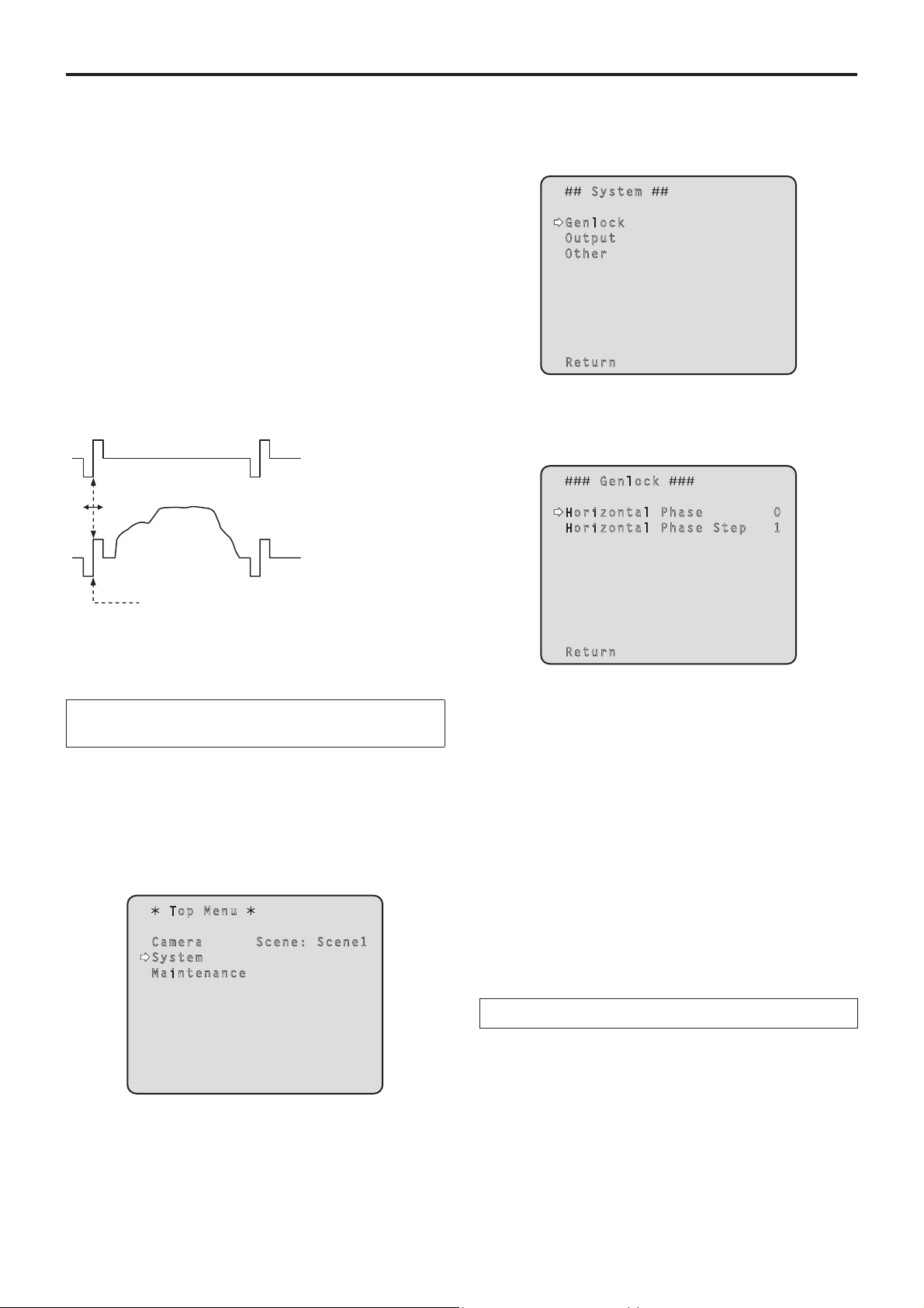
Horizontal phase adjustment
Observe the waveforms of the external sync signal input
( tri-level sync signal) and video signal output on the
dual-trace oscilloscope, and use the wireless remote control
or controller to bring the horizontal phase into alignment.
External sync signal
input (tri-level sync
signal)
3 Press the [] button.
The “System” sub-menu is displayed.
System
Genlock
Output
Other
Return
4 Press the [] or [] button to bring the cursor
to “Genlock”, and press the [] button.
The “Genlock” sub-menu is displayed.
Genlock
Horizontal Phase 0
Horizontal Phase Step 1
Video signal output
Bring the horizontal phase into alignment.
Example: When the tri-level sync phase is adjusted
When performing the operations
using the wireless remote control
1 Follow the operation steps in “Basic
operations” (page 31) to display the Top Menu.
2 Press the [] or [] button to bring the cursor
to “System”.
Top Menu
Camera Scene: Scene1
System
Maintenance
Return
5 Press the [] or [] button to bring the cursor
to “Horizontal Phase”, and press the [] button.
The “Horizontal Phase” value starts blinking.
6 Press the [] or [] button to change the
“Horizontal Phase” value, adjust the value
so that the horizontal phase is brought into
alignment, and press the [] button.
The extent of the phase adjustment can be selected
using “Horizontal Phase Step”.
7 Press the [MENU] button for 2 seconds.
The camera menu display is exited.
28
When performing the operations using the controller
These operations can be performed using the camera
menus by following the operation steps in “Basic operations”
(pages 29 to 36).
Basic operations
Camera menus are displayed on the monitor when the unit’s
settings are to be selected.
The monitor is connected to the video signal output
connector.
The basic camera menu operations involve displaying
sub-menus from the Top Menu items, and selecting settings
on the sub-menus.
Some sub-menus have menu items for performing more
detailed settings.
The camera menu operations are conducted using the
wireless remote control.
If a controller is connected, they can also be conducted using
the controller.
It may be necessary to upgrade the controller’s version in
order to support the AW-HE120.
For further details, consult with your dealer.
Described below are the basic operations for changing the
camera menu item settings using the wireless remote control
and controller (AW-RP655, AW-RP555 or AW-RP50).
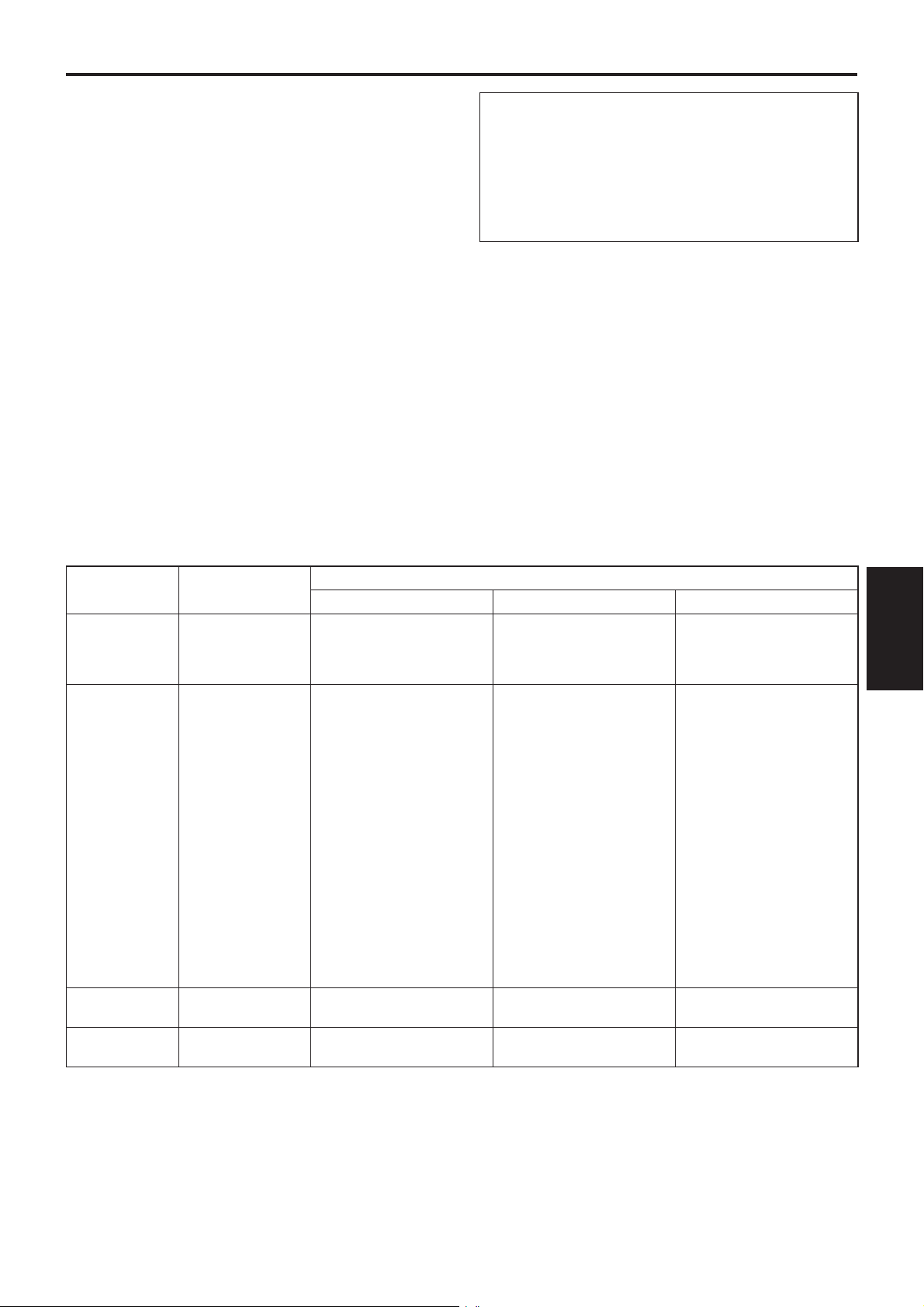
Table of operations
Only the steps taken using the wireless remote
control will be described here for the operations
conducted to select and set the items.
For details of the operations conducted using the
controller, substitute “controller” for “wireless
remote control” when reading the basic operations.
Also, refer to the Operating Instructions of the
controller.
Camera menu
operation
Selecting the unit
to be operated
Displaying the
Top Menu
Selecting the
items
Displaying the
sub-menus
Wireless remote
control
Press the [CAM1],
[CAM2], [CAM3] or
[CAM4] button.
Press the [MENU]
button for 2 seconds.
Press the [] or []
([] or []) button.
Press the [] button.
Controller
AW-RP655 AW-RP555 AW-RP50
Press one of the [1] to [5]
buttons of [CONTROL/
PREVIEW MONITOR OUT
SEL].
1. Press the [MENU] button.
The display on the
AW-RP655’s LCD panel
changes to the menu mode.
2. Turn the jog dial (main)
to display “CAMERA
SETTING” on the LCD
panel, and press the [OK]
button.
3. The scene selection menu
now appears on the LCD
panel so select the scene to
be set, and press the [OK]
button.
4. If the “OPEN CAMERA
MENU? OK Key”
message appears on the
LCD panel, press the [OK]
button again.
Turn the jog dial (main). Press the [YES] or [NO] button. Turn the F1 dial.
Press the jog dial (main). Press the [ITEM] button. Press the F1 dial.
Press one of the [1] to [5]
buttons of [CONTROL].
Press the [MENU] button for
2 seconds.
Press one of the [CAMERA
STATUS/SELECTION] buttons.
Press the [CAMERA OSD]
button for 2 seconds.
Basic
operations
29

Basic operations
(continued)
Camera menu
operation
Returning to the
previous menu
Changing the
settings
Canceling the
setting change
Exiting the
camera menu
operations
Wireless remote
control
With the cursor at
the [Return] position,
press the [] button.
With the cursor at the
item to be changed,
press the [] button to
start the item’s value
blinking.
Use the [], [], []
and [] buttons to
change the value, and
press the [] button to
enter the change.
While the setting
is blinking, press
the [MENU] button
quickly (for less than
2 seconds).
Press the [MENU]
button for 2 seconds.
AW-RP655 AW-RP555 AW-RP50
With the cursor at the [Return]
position, press the jog dial
(main).
1. Press the jog dial (main) to
start the setting blinking.
2. Turn the jog dial (main) to
change the setting.
3. Press the jog dial (main) to
enter the setting (and stop
the blinking).
While the setting is blinking,
press the jog dial (R).
Press the [MENU] button or
[R/B GAIN/PED] button.
Controller
With the cursor at the [Return]
position, press the [ITEM]
button.
1. Press the [ITEM] button to
start the setting blinking.
2. Press the [YES] or [NO]
button to change the setting.
3. Press the [ITEM] button to
enter the setting (and stop
the blinking).
While the setting is blinking,
press the [MENU] button.
Press the [MENU] button for
2 seconds.
With the cursor at the [Return]
position, press the F1 dial.
1. Press the F1 dial to start the
setting blinking.
2. Turn the F1 dial to change
the setting.
3. Press the F1 dial to enter
the setting (and stop the
blinking).
—
Press the [CAMERA OSD]
button for 2 seconds.
Notes
Perform the menu operations and exit from the menus using the controller which displayed the Top Menu.
If a menu operation has been performed or a menu has been exited using another controller, first display the Top Menu
and exit from it using one controller, and then display the Top Menu and exit from it using the other controller.
The procedures used for this unit’s menu operations may differ from the ones used for the convertible cameras and HD
integrated cameras which have already been released on the market.
For details, refer to the Operating Instructions of the camera concerned.
The response speed of the camera differs slightly depending on the controller used.
30
 Loading...