

Panasonic AK-HRP1015G Operating Manual
Operating Guide
Remote Operation Panel
Model No.
Read this document when using the AK-HRP1015G Remote Operation Panel
in conjunction with AW-UE70 Series 4K Integrated Cameras or AW-HE35/
AW-HE38/AW-HE40/AW-HE70 Series HD Integrated Cameras.
AK-HRP1015G
For details of operating Remote Operation Panel AK-HRP1015G, please
visit the Panasonic website (https://pro-av.panasonic.net/manual/en/index.
html), and refer to the Operating Instructions (HTML or PDF).
ENGLISH
DVQP2531ZAW0321AM0 -PS
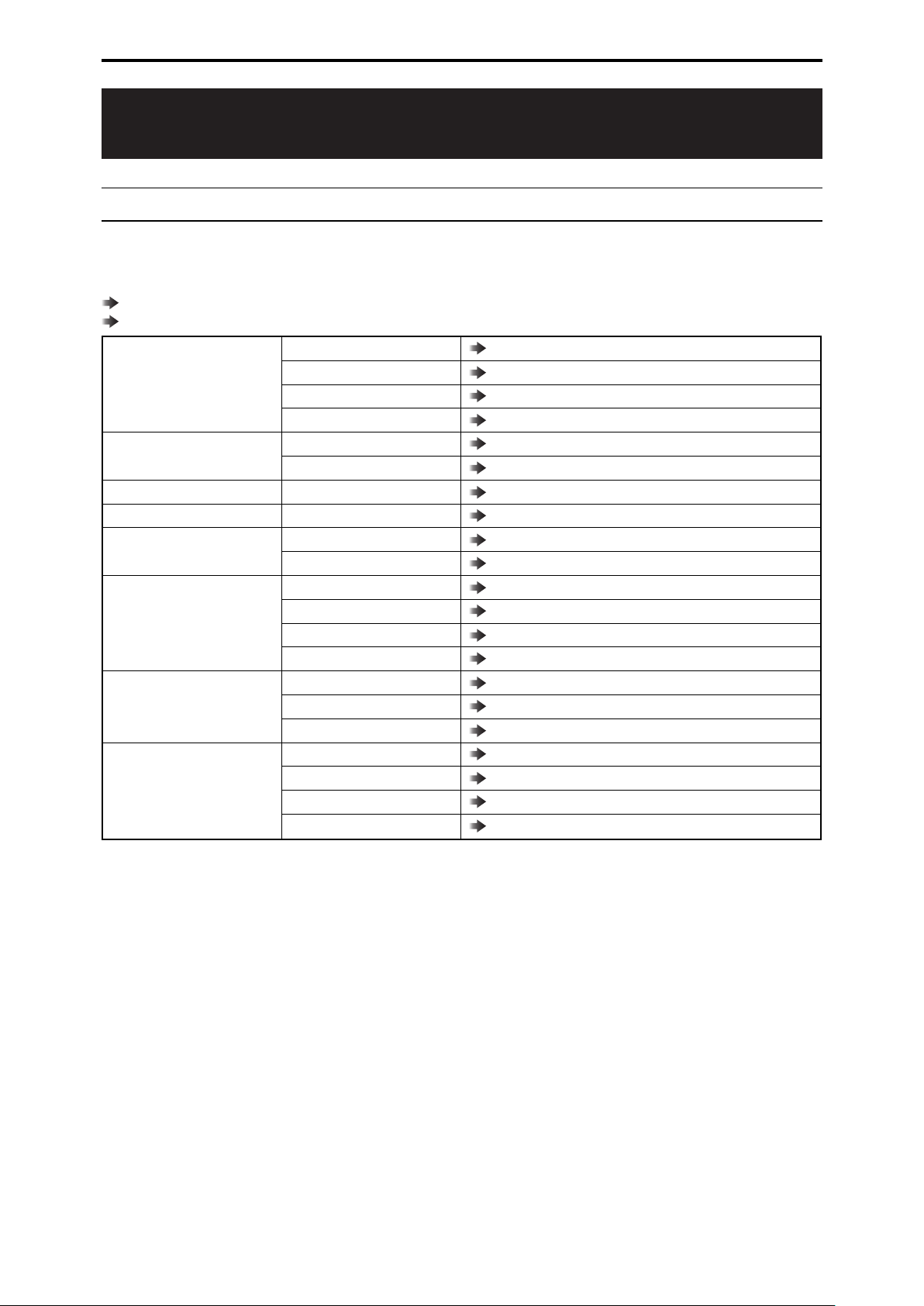
Table of Contents
Connecting the Unit to AW-UE70/AW-HE35/AWHE38/AW-HE40/AW-HE70 Series Cameras
Connection examples 3
Connections 5
Compatible Functions List 6
ROP Menu (when AW-UE70/AW-HE35/AWHE38/AW-HE40/AW-HE70 is connected)
ROP menu list 9
01 SCENE 13
02 SHUTTER SPEED 14
03 FILTER 15
04 CHROMA 16
05 GAIN 17
06 WHITE BALANCE 18
07 GAMMA 19
08 DETAIL 20
09 COLOR CORRECTION 21
10 DNR 24
11 CONTRAST 25
12 LENS CONTROL 26
13 IRIS RELATIVE 27
14 SYSTEM CAM 28
15 CAMERA MENU CONTROL 29
16 ROP SETTING 30
17 CONNECT SETTING 31
18 ROP IP SETTING 32
19 CAMERA IP SETTING 32
20 SWITCHER LINK 32
21 AW CONTROLLER LINK 32
3
9
- 2 -
Supplied AC adapter
[RS-422] connector
AW-UE70
* Prepare a cable that is in accordance
with the following serial connection
cable specifications.
PoE compatible
switching hub or injector
AW-UE70
Supplied AC adapter
LAN cable (straight cable)
LAN cable (straight cable)
Switching hub with
PoE support
[LAN ACT/LINK] connector
Connecting the Unit to AW-UE70/AW-HE35/AW-HE38/AW-HE40/AW-HE70 Series Cameras
Connecting the Unit to AW-UE70/AW-HE35/AWHE38/AW-HE40/AW-HE70 Series Cameras
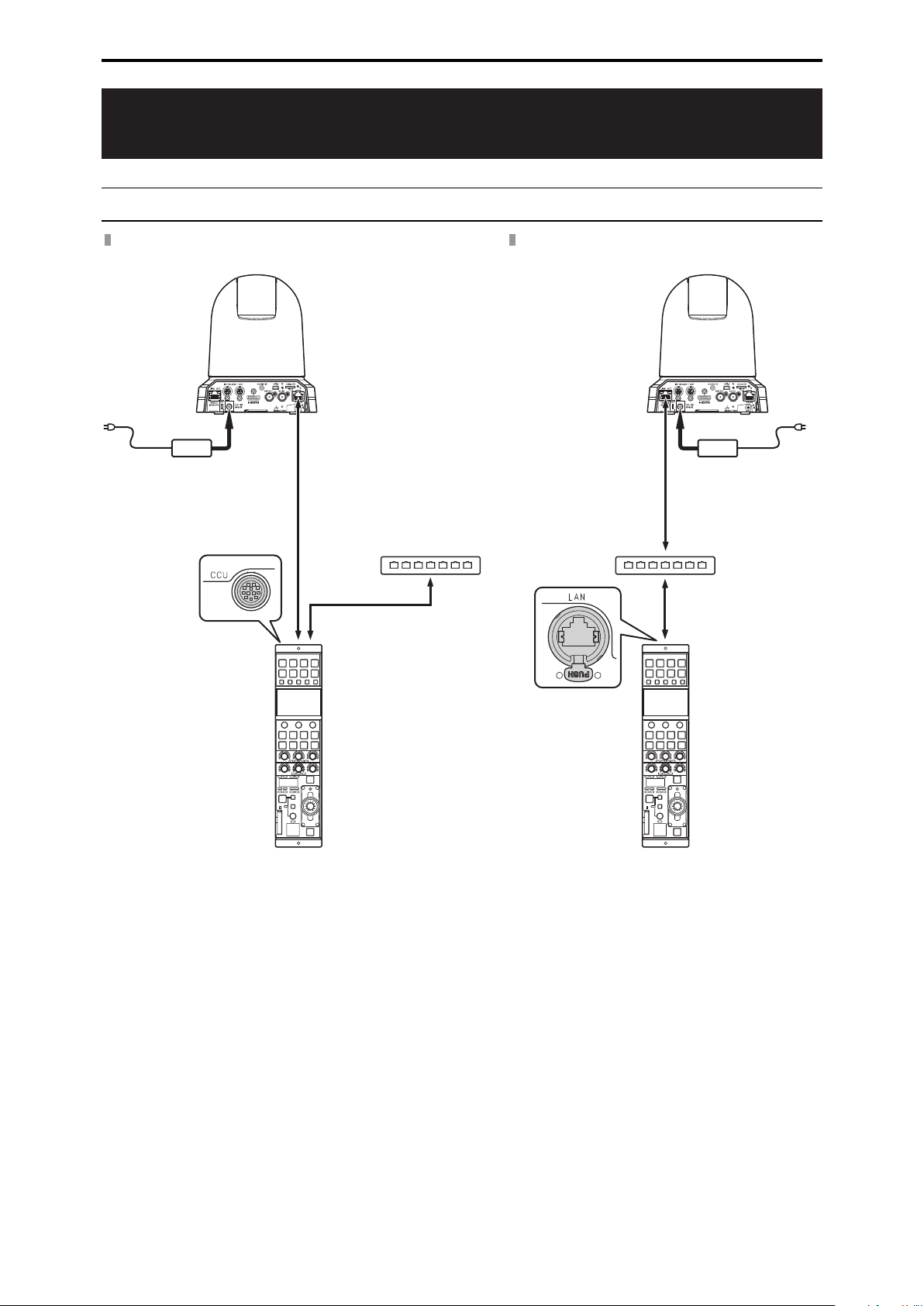
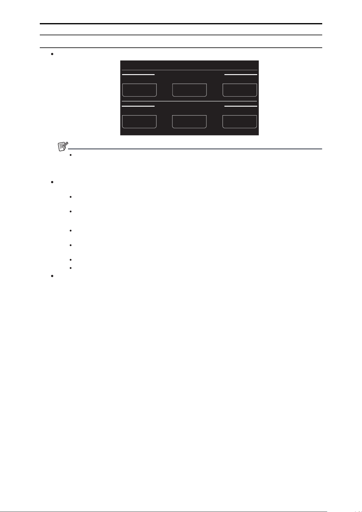
Connection examples
Serial connection with AW-UE70
IP connection with AW-UE70
- 3 -
AW-HE35/AW-HE38/
AW-HE40/AW-HE70
Supplied AC adapter
[RS-422] connector
* Prepare a cable that is in accordance
with the following serial connection
cable specifications.
PoE compatible
switching hub or injector
Supplied AC adapter
AW-HE35/AW-HE38/
AW-HE40/AW-HE70
LAN cable (straight cable)
LAN cable (straight cable)
Switching hub with
PoE support
[LAN ACT/LINK] connector
ヒ
ヤモヮチチュモヵユドラナ⾺
⾺
⾼
⾼
ビ
ヤヰヮチチュモヵユドロナ
ピ
ヤヰヮチチヤヰワヵドラナ
フ
ヤヰヮチチヤヰワヵドロナ
ヤモヮēチンヰヱ
ヤモヮēチンヰヱ
ンヰヱチēチヤモヮ
ンヰヱチēチヤモヮ
ブ
ヤヰヮチチワㄐハチモ
プ
ヤヰヮチチワㄐハチャ
ヘ
ヤヰヮチチワㄐハチヤ
ベ
ヤヰヮチチワㄐハチュ
ペ
ヒビチヷ
ヒパ
ヨワュ
ヒ
ヨンュ
ヵモロロヺ
ンヹュノ
ヵヹュノ
ヵヹュヌ
ンヹュヌ
チ⾼
チ⾼
ビ
ピ
フ
ブ
プ
ヘ
ベ
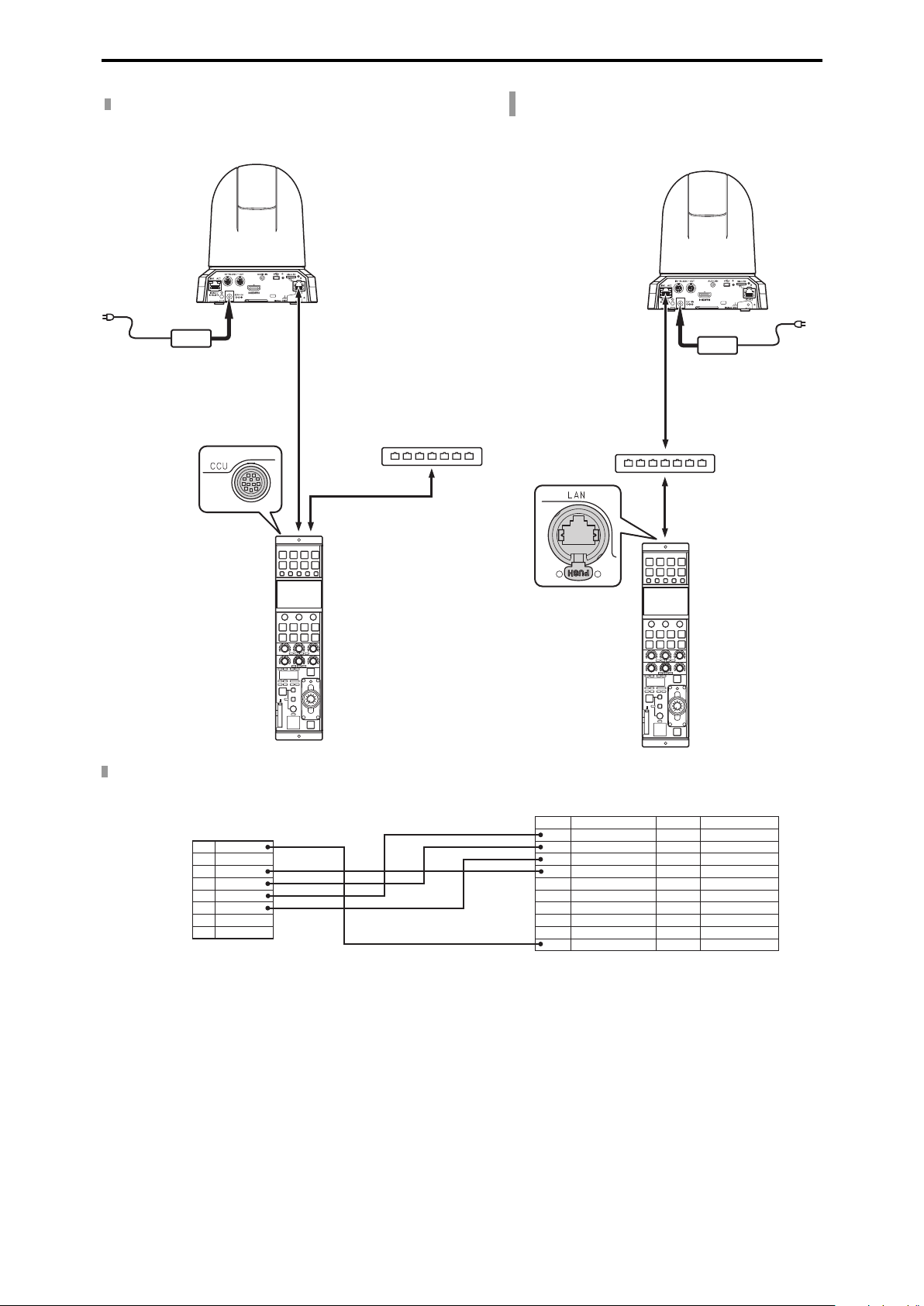
ラㄊㄓㄐㄔㄆホチランヒパモノヒパヱノヒパブドヘピナ
AW-UE70/AW-HE35/AW-HE38/
AW-HE40/AW-HE70
[RS-422] connector side (RJ45)
AK-HRP1015G
[CCU] connector side
Pin No. Function Polarity Flow of signal
Connecting the Unit to AW-UE70/AW-HE35/AW-HE38/AW-HE40/AW-HE70 Series Cameras
Serial connection with AW-HE35/AW-HE38/AW-HE40/AW-HE70
IP connection with AW-HE35/AW-HE38/AWHE40/AW-HE70
Serial connection cable specificatio ns
- 4 -
ヒチバチヒヘ
ヤヰワワユヤヵチヴユヵヵリワヨ
ヤヰワワユヤヵチヮヰュユドㄑㄖㄔㄉナ
ヤモヮビ
ヤヰワワユヤヵチヮヰュユドㄑㄖㄔㄉナ
ヤモヮブ
ヤモヮピ
ヤモヮプ
ヤモヮヒ
ヤモヮフ
ヴㄆㄓㄊㄍ
ドモヸピナ
ロモワ
ドモヸピナ
ワヰワ
ワヰワワヰワワヰワ
NOTE
Connecting the Unit to AW-UE70/AW-HE35/AW-HE38/AW-HE40/AW-HE70 Series Cameras
Connections
Set the conne ction setting to [Serial(AW3)] or [LAN(AW3)] in the [CONNECT SETTING] menu .
To connect with the AW-UE70 /AW-HE35/AW-HE38/AW-HE40/AW-HE70, upgrade the system version of the unit to
2.00-00-0.00 or later.
When connecting, observe the following points.
Serial connection
Use a dedicated cable to connect the [CCU] connecto r of this unit to the [RS-422] connecto r of the AW-UE70/AWHE35/AW-HE38/AW-HE40/AW-HE70.
Use a PoE power supply for the power supply.
LAN connection
Connect the [LAN] conne ctor on this unit to the [LAN ACT/LINK] conne ctor on the AW-UE70/AW-HE35/AW-HE38/AWHE40/AW-HE70 using a LAN cable (sold separately).
Configure the camera IP add ress and port number settings of the conne ction destinations in [CAMERA IP SETTING] as
well.
This unit can be powered using PoE. Use a switching hub with PoE support.
Use a straight cable (category 5e or higher; up to 100 m (328.0 ft) in length) for the LAN cable (STP).
For details on switching hubs and PoE injectors that have been verified to support PoE, consult with your dealer.
- 5 -
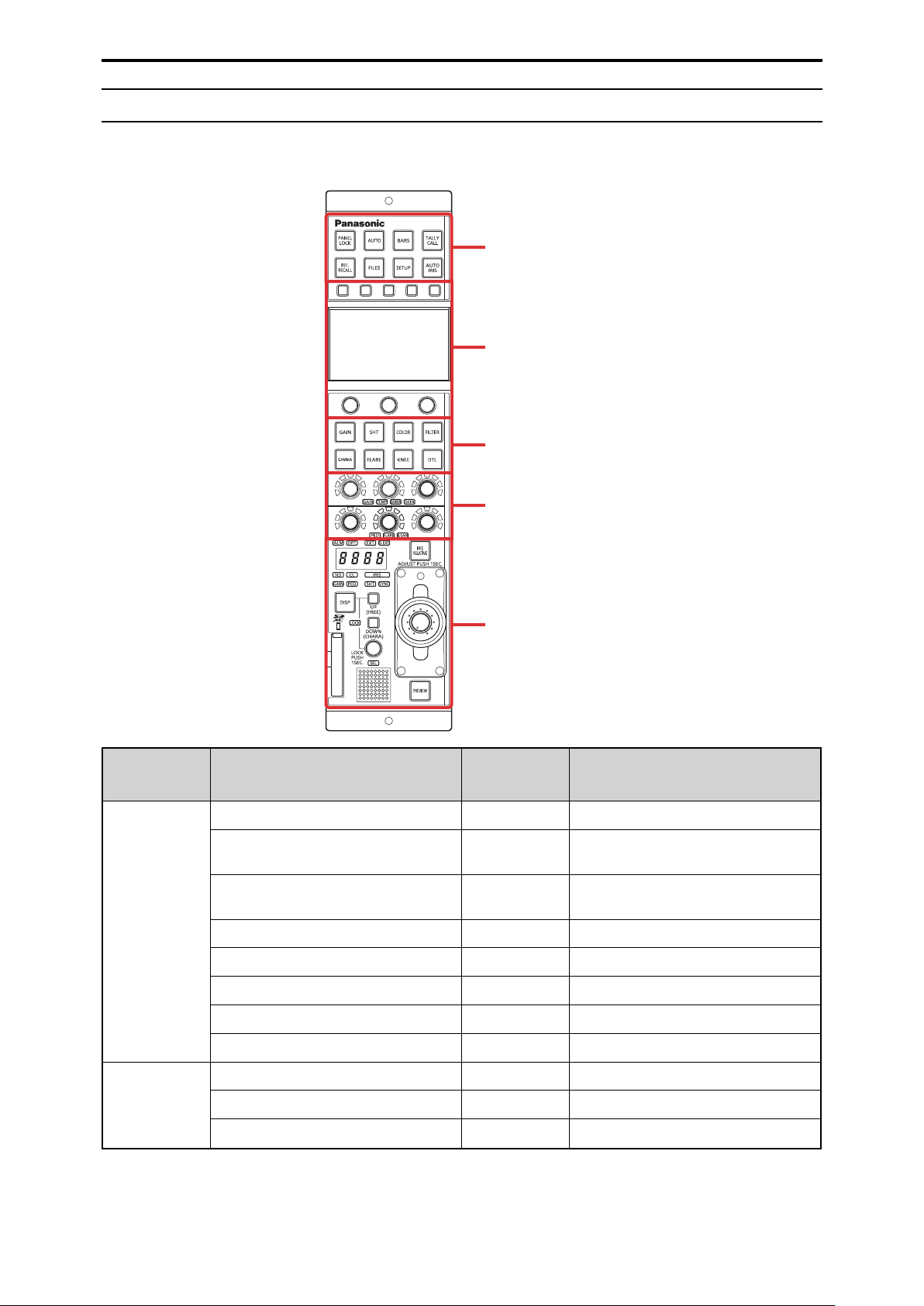
Front panel 1
Front panel 2
Front panel 3
Front panel 4
Front panel 5
Front panel 6
Connecting the Unit to AW-UE70/AW-HE35/AW-HE38/AW-HE40/AW-HE70 Series Cameras
Compatible Functions List
When the unit is used in conjunction with an AW-UE70 Series 4K Integrated Camera or AW-HE35/AW-HE38 /AW-HE40/AW-HE70 Series
HD Integrated Camera, there will be functions tha t are limited or disabled for some of the unit’s buttons, dials, and othe r controls. Be sure to
refer to the following table.
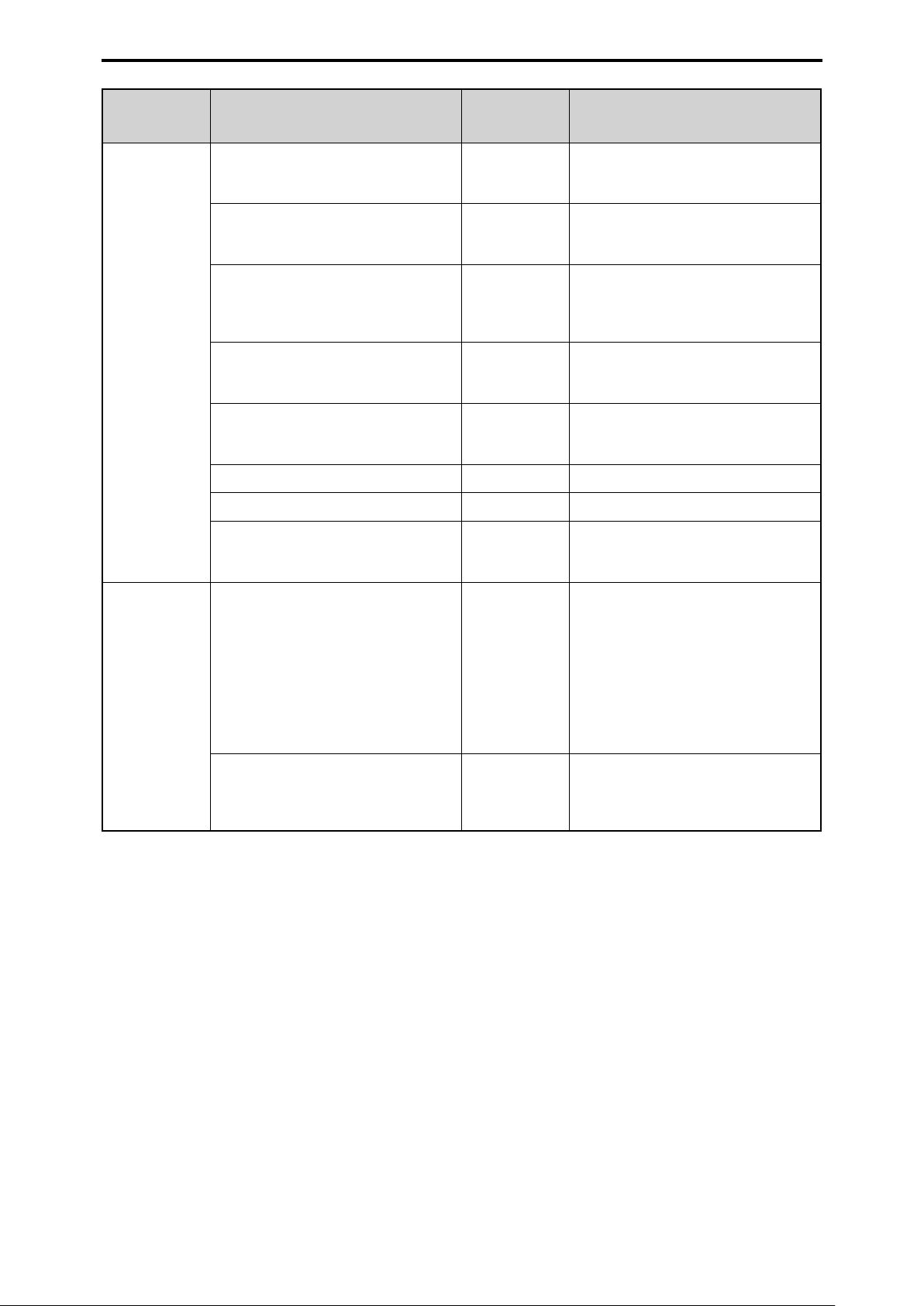
Number Part name
Front pan el 1
Front pan el 2
[PANEL LOCK] button ✓
[AUTO] button ✓ If auto setup has been assigned , this will not
[BARS] butto n ✓ Only the ON/OFF for the color bar signal
[TALLY/CALL] lamp/button ×
[REF. RECALL] button ×
[FILES] button ✓ This is always lit.
[SETUP] button ✓
[AUTO IRIS] button ✓
Function buttons ✓
LCD panel ✓
Menu operation dials ✓
✓ : Enabled
×: Disabled
Remark s
ope rate.
output will function.
- 6 -
Connecting the Unit to AW-UE70/AW-HE35/AW-HE38/AW-HE40/AW-HE70 Series Cameras
Number Part name
[GAIN] button ✓ When this button is pressed, the gain menu
[SHT] button ✓ When this button is pressed, the shutte r
[COLOR] button ✓ The menus will switch with each press of the
Front pan el 3
[FILTER] button ✓ When this button is pressed, the filter menu
[GAMMA] button ✓ When this button is pressed , the gamma
[FLARE] butto n ×
[KNEE] butto n ×
[DTL] button ✓ The menus will switch with each press of the
✓ : Enabled
×: Disabled
Remark s
app ea rs on the LCD panel. The button is lit
during menu display.
menu appears on the LCD pan el. The button
is lit during menu display.
button . The button is lit during menu display.
[CHROMA] > [COLOR CORRECTION] >
Menu off (status screen)
app ea rs on the LCD panel. The button is lit
during menu display.
menu appears on the LCD pan el. The button
is lit during menu display.
button . The button is lit during menu display.
[DETAIL ] > [DNR] > Menu off (status screen )
Front pan el 4
[GAIN], [TEMP], [GAMMA], [SKIN]
adjustment block
[PED], [FLARE], [B.GAM] adjustment block ✓ When [PED] is lit, [M.PED] is adjusted using
✓ When [GAIN] is lit, [GAIN R] and [GAIN B] are
adjusted using the red (R) and blue (B)
adjustment dials respectively.
When [TEMP] is lit, [COLOR TEMP] is
adjusted using the green (G) adjustment
dial.
When [GAMMA] is lit, the master gamma is
adjusted using the green (G) adjustment
dial.
[SKIN] adjustmen t is disabled.
the green (G) adjustment dial.
[FLARE] and [B.GAM] adjustment is
disabled.
- 7 -
Connecting the Unit to AW-UE70/AW-HE35/AW-HE38/AW-HE40/AW-HE70 Series Cameras
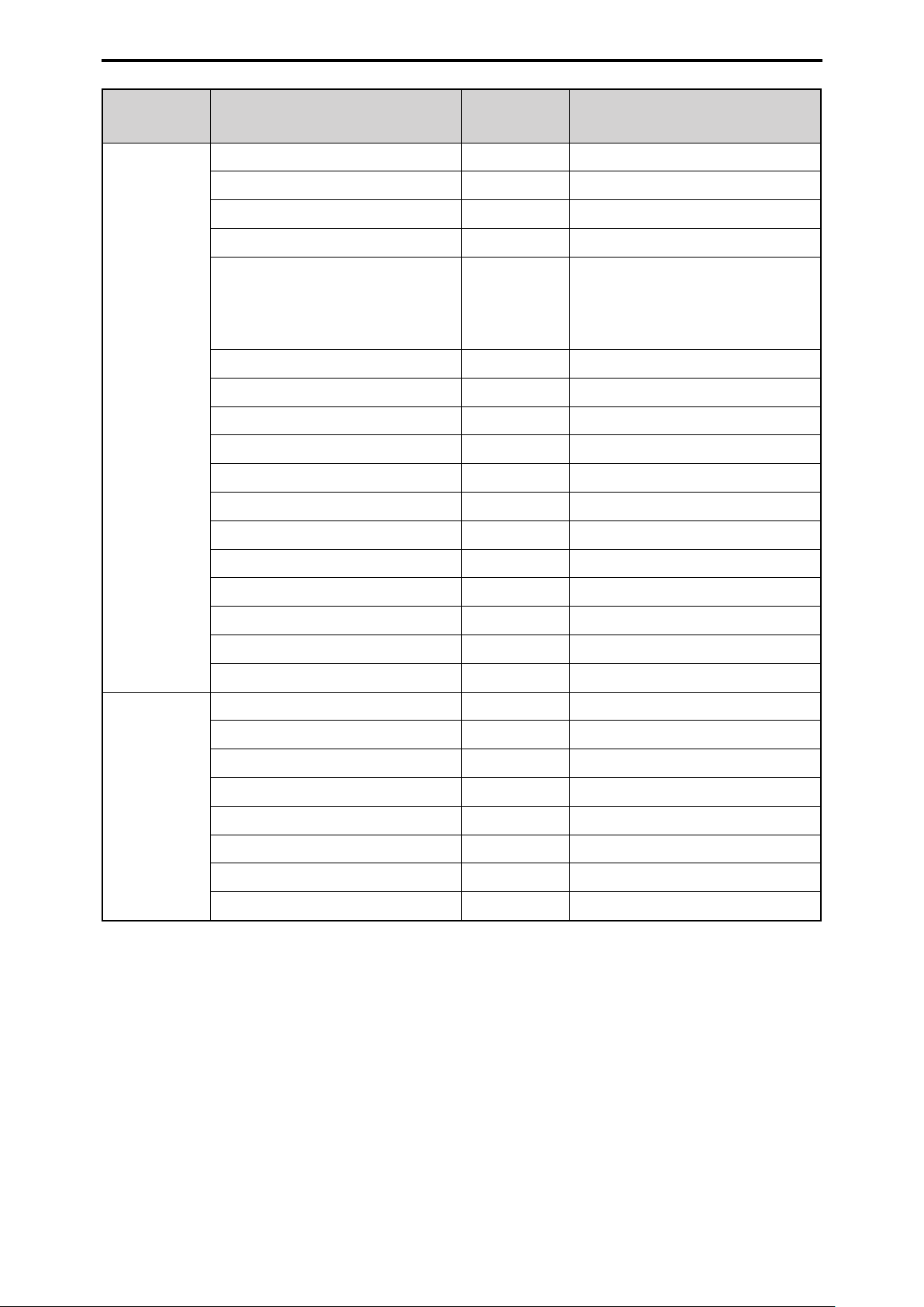
Number Part name
[ALM] indicator ✓
[OPT] indicator ×
[EXT] indicator ×
[D.EXT] indicator ✓
Adjustment value display ✓ A value is also not displayed when
[ND] indicator ✓ This is enabled only for the AW-UE70.
[CC] indicator ✓ This lights but does not function.
Front pan el 5
[IRIS] indicator ✓ The iris value is not displayed.
[GAIN] indicator ✓
[PED] indicator ✓
[SHT] indicato r ✓
[SYNC] indicator ✓
✓ : Enabled
×: Disabled
Remark s
[SHUTTER] is [SYNC]. The display will be bar
display.
When the shutte r speed value is “10000”,
“9999” is displayed.
Front pan el 6
[DISP] button ✓
[UP (FREE)] button ✓
[DOWN (CHARA)] button ✓
[LOCK] indicator ✓
[SEL] dial ✓
Memory card slot ✓
Memory card access indicator ✓
Camera number/tally display ✓
[IRIS RELATIVE] button ✓
Torque adjustment screw ✓
IRIS lever ✓
Master pedestal dial ✓
[PREVIEW] button ×
- 8 -
ROP Menu (when AW-UE70/AW-HE35 /AW-HE38/AW-HE40/AW-HE70 is conne cted)
ROP Menu (when AW-UE70/AW-HE35/AW-HE38/AWHE40/AW-HE70 is connected)
ROP menu list
When an AW-UE70 4K Integrated Camera or AW-HE35/AW-HE38/AW-HE40/AW-HE70 HD Integrated Camera is connected, the ROP
menu will be as follows.
For details on menu ope ration s, refer to the following section s in the Operating Instructions.
“Displaying menus”
“Basic menu operations”
MANUAL1(push)
01 SCENE
02 SHUTTER SPEED
03 FILTER ND
04 CHROMA LEVEL
05 GAIN
06 WHITE BALANCE
07 GAMMA
08 DETAIL
MANUAL2(push)
MANUAL3(push)
FULL AUTO(push)
MODE
SPEED
GAIN
AGC MAX GAIN
MODE
COLOR TEMP
GAIN R
GAIN B
TYPE
LEVEL
DRS
DTL
LEVEL H
LEVEL L
FLESH TONE MD
“MANUAL1(push)” (see page 13)
“MANUAL2(push)” (see page 13)
“MANUAL3(push)” (see page 13)
“FULL AUTO(push)” (see page 13)
“MODE” (see page 14)
“SPEED” (see page 14)
“ND” (see page 15)
“LEVEL” (see page 16)
“GAIN” (see page 17)
“AGC MAX GAIN” (see page 17)
“MODE” (see page 18)
“COLOR TEMP” (see page 18)
“GAIN R” (see page 18)
“GAIN B” (see page 18)
“TYPE” (see page 19)
“LEVEL” (see page 19)
“DRS” (see page 19)
“DTL” (see page 20)
“LEVEL H” (see page 20)
“LEVEL L” (see page 20)
“FLESH TONE MD” (see page 20)
- 9 -

ROP Menu (when AW-UE70/AW-HE35 /AW-HE38/AW-HE40/AW-HE70 is conne cted)
TYPE
COLOR CORRECT
SAT
PHASE
SAT B
PHASE B
SAT B_B_Mg
PHASE B_B_Mg
SAT B_Mg_Mg
PHASE B_Mg_Mg
SAT Mg
PHASE Mg
SAT Mg_R
PHASE Mg_R
SAT R
PHASE R
SAT R_R_Yl
09 COLOR CORRECTION
10 DNR DNR
11 CONTRAST
12 LENS CONTROL
PHASE R_R_Yl
SAT R_Yl_Yl
PHASE R_Yl_Yl
SAT Yl
PHASE Yl
SAT Yl_Yl_G
PHASE Yl_Yl_G
SAT Yl_G_G
PHASE Yl_G_G
SAT G
PHASE G
SAT G_Cy
PHASE G_Cy
SAT Cy
PHASE Cy
SAT Cy_Cy_B
PHASE Cy_Cy_B
SAT Cy_B_B
PHASE Cy_B_B
CONTRAST MODE
CONTRAST LEVEL
FRAME MIX
A.F.MIX MAX GAIN
DAY/NIGHT
FOCUS MODE
FOCUS SPEED
FOCUS
ZOOM WIDE
ZOOM SPEED
ZOOM TELE
“TYPE” (see page 22)
“COLOR CORRECT” (see page 22)
“SAT” (see page 22)
“PHASE” (see page 22)
“SAT B” (see page 22)
“PHASE B” (see page 22)
“SAT B_B_Mg” (see page 22)
“PHASE B_B_Mg” (see page 22)
“SAT B_Mg_Mg” (see page 22)
“PHASE B_Mg_Mg” (see page 22)
“SAT Mg” (see page 22)
“PHASE Mg” (see page 22)
“SAT Mg_R” (see page 23)
“PHASE Mg_R” (see page 23)
“SAT R” (see page 23)
“PHASE R” (see page 23)
“SAT R_R_Yl” (see page 23)
“PHASE R_R_Yl” (see page 23)
“SAT R_Yl_Yl” (see page 23)
“PHASE R_Yl_Yl” (see page 23)
“SAT Yl” (see page 23)
“PHASE Yl” (see page 23)
“SAT Yl_Yl_G” (see page 23)
“PHASE Yl_Yl_G” (see page 23)
“SAT Yl_G_G” (see page 23)
“PHASE Yl_G_G” (see page 23)
“SAT G” (see page 23)
“PHASE G” (see page 23)
“SAT G_Cy” (see page 23)
“PHASE G_Cy” (see page 23)
“SAT Cy” (see page 23)
“PHASE Cy” (see page 23)
“SAT Cy_Cy_B” (see page 23)
“PHASE Cy_Cy_B” (see page 23)
“SAT Cy_B_B” (see page 23)
“PHASE Cy_B_B” (see page 23)
“DNR” (see page 24)
“CONTRAST MODE” (see page 25)
“CONTRAST LEVEL” (see page 25)
“FRAME MIX” (see page 25)
“A.F.MIX MAX GAIN” (see page 25)
“DAY/NIGHT” (see page 25)
“FOCUS MODE” (see page 26)
“FOCUS SPEED” (see page 26)
“FOCUS” (see page 26)
“ZOOM WIDE” (see page 26)
“ZOOM SPEED” (see page 26)
“ZOOM TELE” (see page 26)
- 10 -
 Loading...