

Page 1
Before operating this product, please read the instructions carefully and save this manual for future use.
Digital Video Cassette Recorder
Operating Instructions
AJ-
P
ENGLISH
AJ-
E
Model No.
Printed in Japan
VQT0L54
EP
S0704A0 -M
D
Page 2
– 2 –
IMPORTANT
“Unauthorized recording of copyrighted television programmes, video tapes and other materials
may infringe the right of copyright owners and be contrary to copyright laws.”
For AJ-SD93P
THIS APPARATUS MUST BE GROUNDED
To ensure safe operation the three-pin plug must be
inserted only into a standard three-pin power outlet
which is effectively grounded through normal
household wiring.
Extension cords used with the equipment must be
threecore and be correctly wired to provide connection
to the ground. Incorrectly wired extension cords can be
extremely hazardous.
The fact that the equipment operates satisfactorily
does not imply that it is grounded, and the installation
is not necessarily safe. For your safety, if in any doubt
about the effective grounding of the equipment or
power outlet, please consult a qualified electrician.
WARNING:
TO REDUCE THE RISK OF FIRE OR SHOCK
HAZARD, DO NOT EXPOSE THIS EQUIPMENT
TO RAIN OR MOISTURE.
TO REDUCE THE RISK OF FIRE OR SHOCK
HAZARD, KEEP THIS EQUIPMENT AWAY FROM
ALL LIQUIDS-USE AND STORE ONLY IN
LOCATIONS WHICH ARE NOT EXPOSED TO
THE RISK OF DRIPPING OR SPLASHING
LIQUIDS, AND DO NOT PLACE ANY LIQUID
CONTAINERS ON TOP OF THE EQUIPMENT.
CAUTION:
Do not install or place this deck in a bookcase,
built-in cabinet or any other confined space in
order to maintain adequate ventilation. Ensure
that curtains and any other materials do not
obstruct the ventilation to prevent risk of
electric shock or fire hazard due to overheating.
CAUTION:
TO REDUCE THE RISK OF FIRE OR SHOCK
HAZARD AND ANNOYING INTERFERENCE,
USE THE RECOMMENDED ACCESSORIES
ONLY.
CAUTION:
TO REDUCE THE RISK OF FIRE OR SHOCK
HAZARD, REFER MOUNTING OF THE
OPTIONAL INTERFACE BOARD TO QUALIFIED
SERVICE PERSONNEL.
CAUTION:
TO REDUCE THE RISK OF FIRE OR SHOCK
HAZARD, REFER CHANGE OF SWITCH
SETTING INSIDE THE DECK TO QUALIFIED
SERVICE PERSONNEL.
CAUTION:
This apparatus can be operated at a voltage in the
range of 100 – 240 V AC.
Voltage other than 120 V is not intended for U.S.A.
and Canada.
CAUTION:
Operation at a voltage other than 120 V AC may
require the use of a different AC plug. Please
contact either a local or foreign Panasonic
authorized service center for assistance in
selecting an alternate AC plug.
CAUTION:
Even when the Power Switch is in the OFF
position, a small current flows the filter circuit.
FCC Note:
This equipment has been tested and found to
comply with the limits for a class A digital device,
pursuant to Part 15 of the FCC Rules. These limits
are designed to provide reasonable protection
against harmful interference when the equipment is
operated in a commercial environment. This
equipment generates, uses, and can radiate radio
frequency energy and, if not installed and used in
accordance with the instruction manual, may cause
harmful interference to radio communications.
Operation of this equipment in a residential area is
likely to cause harmful interference in which case
the user will be required to correct the interference
at his own expense.
Warning: To assure continued FCC emission limit
compliance, the user must use only shielded interface
cables when connecting to external units. Also any
unauthorized changes or modifications to this
equipment could void the user’s authority to operate it.
indicates safety information.
CAUTION:
TO COMPLETELY DISCONNECT THIS
APPARATUS FROM THE AC MAINS,
DISCONNECT THE POWER SUPPLY CORD
PLUG FROM THE AC RECEPTACLE.
THE AC OUTLET (MAIN SOCKET) SHALL BE
INSTALLED NEAR THE EQUIPMENT AND
SHALL BE EASILY ACCESSIBLE.
Page 3
– 3 –
indicates safety information.
For AJ-SD93E
FOR U.K. ONLY
This appliance is supplied with a moulded three pin
mains plug for your safety and convenience.
A 13 amp fuse is fitted in this plug.
Should the fuse need to be replaced please ensure that
the replacement fuse has a rating of 13 amps and that it
is approved by ASTA or BSI to BS1362.
Check for the ASTA mark or the BSI mark on the
body of the fuse.
If the plug contains a removable fuse cover you must
ensure that it is refitted when the fuse is replaced.
If you lose the fuse cover the plug must not be used
until a replacement cover is obtained.
A replacement fuse cover can be purchased from your
local Panasonic Dealer.
IF THE FITTED MOULDED PLUG IS UNSUITABLE
FOR THE SOCKET OUTLET IN YOUR HOME THEN
THE FUSE SHOULD BE REMOVED AND THE PLUG
CUT OFF AND DISPOSED OF SAFELY. THERE IS A
DANGER OF SEVERE ELECTRICAL SHOCK IF THE
CUT OFF PLUG IS INSERTED INTO ANY 13 AMP
SOCKET.
If a new plug is to be fitted please observe the wiring
code as shown below.
If in any doubt please consult a qualified electrician.
WARNING: THIS APPLIANCE MUST BE EARTHED.
IMPORTANT: The wires in this mains lead are coloured
in accordance with the following code:
Green-and-Yellow: Earth
Blue: Neutral
Brown: Live
As the colours of the wires in the mains lead of this
appliance may not correspond with the coloured
markings identifying the terminals in your plug, proceed
as follows:
The wire which is coloured GREEN-AND-YELLOW
must be connected to the terminal in the plug which is
marked with the letter E or by the Earth symbol or
coloured GREEN or GREEN-AND-YELLOW.
The wire which is coloured BLUE must be connected
to the terminal in the plug which is marked with the
letter N or coloured BLACK.
The wire which is coloured BROWN must be
connected to the terminal in the plug which is marked
with the letter L or coloured RED.
FOR YOUR SAFETY PLEASE READ THE FOLLOWING TEXT CAREFULLY.
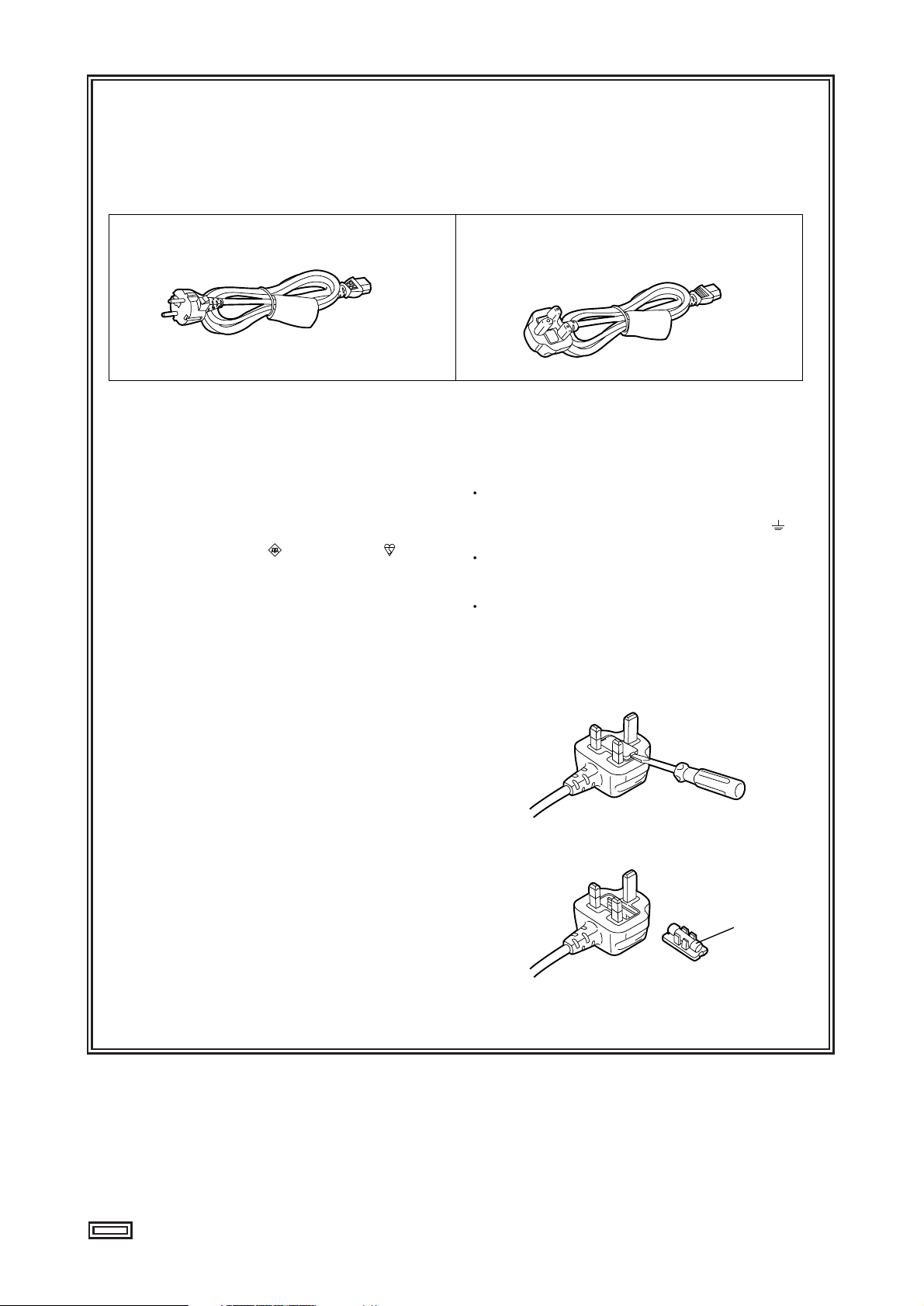
This product is equipped with 2 types of AC mains cable. One is for continental Europe, etc. and the other one is only
for U.K.
Appropriate mains cable must be used in each local area, since the other type of mains cable is not suitable.
FOR CONTINENTAL EUROPE, ETC.
Not to be used in the U.K.
FOR U.K. ONLY
If the plug supplied is not suitable for your socket
outlet, it should be cut off and appropriate one fitted.
Caution for AC Mains Lead
How to replace the fuse
1.Open the fuse compartment with a screwdriver.
2.Replace the fuse.
Fuse
Page 4
– 4 –
indicates safety information.
For AJ-SD93E
IMPORTANT
“Unauthorized recording of copyrighted television
programmes, video tapes and other materials may
infringe the right of copyright owners and be
contrary to copyright laws.”
Operating precaution
Operation near any appliance which generates strong
magnetic fields may give rise to noise in the
video and audio signals. If this should be the case,
deal with the situation by, for instance, moving the
source of the magnetic fields away from the unit before
operation.
THIS APPARATUS MUST BE EARTHED
To ensure safe operation the three-pin plug must be
inserted only into a standard three-pin power point
which is effectively earthed through the normal household wiring.
Extension cords used with the equipment must be
three-core and be correctly wired to provide
connection to earth. Wrongly wired extension cords
are a major cause of fatalities.
The fact that the equipment operates satisfactorily
does not imply that the power point is earthed and that
the installation is completely safe. For your safety, if in
any doubt about the effective earthing of the power
point, consult a qualified electrician.
DO NOT REMOVE PANEL COVER BY
UNSCREWING.
To reduce the risk of electric shock, do not remove
cover. No user serviceable parts inside.
Refer servicing to qualified service personnel.
WARNING:
TO REDUCE THE RISK OF FIRE OR SHOCK
HAZARD, KEEP THIS EQUIPMENT AWAY FROM
ALL LIQUIDS-USE AND STORE ONLY IN
LOCATIONS WHICH ARE NOT EXPOSED TO
THE RISK OF DRIPPING OR SPLASHING
LIQUIDS, AND DO NOT PLACE ANY LIQUID
CONTAINERS ON TOP OF THE EQUIPMENT.
CAUTION:
TO REDUCE THE RISK OF FIRE OR SHOCK
HAZARD, REFER MOUNTING OF THE
OPTIONAL INTERFACE BOARD TO
AUTHORIZED SERVICE PERSONNEL.
CAUTION:
TO REDUCE THE RISK OF FIRE OR SHOCK
HAZARD, REFER CHANGE OF SWITCH
SETTING INSIDE THE DECK TO QUALIFIED
SERVICE PERSONNEL.
CAUTION:
Do not install or place this deck in a bookcase,
built-in cabinet or any other confined space in
order to maintain adequate ventilation. Ensure
that curtains and any other materials do not
obstruct the ventilation to prevent risk of
electric shock or fire hazard due to overheating.
CAUTION:
Even when the Power Switch is in the OFF
position, a small current flows the filter circuit.
CAUTION:
TO REDUCE THE RISK OF FIRE OR SHOCK
HAZARD AND ANNOYING INTERFERENCE,
USE THE RECOMMENDED ACCESSORIES
ONLY.
CAUTION:
TO COMPLETELY DISCONNECT THIS
APPARATUS FROM THE AC MAINS,
DISCONNECT THE POWER SUPPLY CORD
PLUG FROM THE AC RECEPTACLE.
THE AC OUTLET (MAIN SOCKET) SHALL BE
INSTALLED NEAR THE EQUIPMENT AND
SHALL BE EASILY ACCESSIBLE.
Page 5

– 5 –
Contents
Introduction ......................................................6
Included accessories ......................................6
Optional boards ...............................................6
Features ...........................................................7
Parts and their functions .................................8
• Front Panel ........................................................8
• Display Panel...................................................11
• Rear Panel.......................................................12
Tapes ...............................................................13
IEEE 1394 digital interface.............................14
Search stick ....................................................15
PF (Programmable Function) ........................15
• Registering the items in the PF buttons...........15
• Performing operations using the PF buttons....15
Repeat playback .............................................16
Setup (initial settings)....................................17
Setup menus...................................................18
• SYSTEM menu ................................................20
• USER menus ...................................................21
<BASIC> .....................................................21
<OPERATION>...........................................23
<INTERFACE> ...........................................24
<TAPE PROTECT> ....................................25
<TIME CODE>............................................26
<VIDEO>.....................................................28
<AUDIO> ....................................................30
<V BLANK>.................................................32
<DIF> ..........................................................33
<MENU> .....................................................34
Time code/user bit..........................................35
Superimpose screen ......................................36
Video head cleaning.......................................37
Condensation .................................................37
Maintenance....................................................37
Error messages ..............................................38
Specifications .................................................43
Page 6

– 6 –
Introduction
The model AJ-SD93 multi-purpose digital VTR uses small,
1/4-inch wide cassette tapes to record and play back
images with a high picture quality at a video recording rate
of 50 Mbps while it can also record and play back
DVCPRO (25 Mbps) format tapes as well as play back
consumer-use DV/DVCAM tapes.
It comes with the following features.
•This high-picture-quality VTR incorporates digital
compression technology to dramatically reduce the
deterioration of the picture quality and sound quality
resulting from dubbing.
•It is equipped with an IEEE 1394 interface as a
standard feature and, in compliance with the IEEE
1394 standard, it can digitally transmit video and
audio signals as well as time code signals to a digital
VTR, etc.
•It has a compact and lightweight design so that it can
readily be carried around or easily installed in a rack.
3-pin power cord x 1
Included accessories
•Analog interface board:
AJ-YA93P
•SDI interface board:
AJ-YA94G
Use only the optional boards listed above.
Optional boards
Page 7

– 7 –
Features
Compact and lightweight
This unit is a DVCPRO50 digital VTR which uses 1/4inch wide cassette tapes. Its compact and lightweight
design makes it ideal as a feeder for non-linear editing
or as a viewer installed on a desk-top, for instance.
Up to 92 minutes of recording
M cassettes (max. 33 minutes: using the AJ-5P33MP)
and L cassettes (max. 92 minutes: using the AJ5P92LP) can be used with this unit. Tape width is a
compact 1/4-inch.
Superior picture quality
Superior picture quality is achieved through 4:2:2
component signal recording at 2 times the recording
rate of the DVCPRO format.
4-channel, high-sound-quality digital audio
The unit can record and play back 4-channel PCM
audio. (However, it does not support cue recording or
playback.)
IEEE 1394 digital input/output
The IEEE 1394 digital interface, which is provided as a
standard feature, enables DVCPRO50 or DVCPRO/DV
compressed digital video and audio signals to be input
and output with no accompanying deterioration of the
picture quality.
Compatibility with DVCPRO (25 Mbps) format
This unit can record, play back and edit material in the
DVCPRO (25 Mbps) format.
Compatibility with general consumer video
equipment
DV cassette tapes containing material shot with a
consumer digital camera or the like can be played
back on this unit. A cassette adapter (AJ-CS455P) is
necessary when a mini DV cassette tape is to be used.
Digital slow motion
Panasonic's original digital slow-motion technology
makes it possible to obtain clear pictures even during
slow playback at speeds ranging from -0.43x to +0.43x.
(DVCPRO, DVCPRO50 only)
Search stick
The unit comes with a search stick (stick controller). It
is used to control variable-speed playback during
searches, etc.
In addition, the settings for the on-screen menus and
time code generator can also be accomplished easily
using the search stick.
PF (Programmable Function) buttons
The unit comes with three PF buttons. Any three
frequently used setup menus can be selected, and by
operating these buttons on the front panel, it is possible
to change the menu settings.
Recording and playback of UMID information
Recording and playback of UMID (Unique Material
Identifier) information complies with the SMPTE 330M
standard.
UMID information can be checked on the DIAG menu.
Time code
The unit incorporates a TCG (time code
generator)/TCR (time code reader). In addition to the
internal time code, use of the analog interface board
(option: AJ-YA93P) enables the external time code
input or input signal VITC to be recorded on the unit as
the time code.
Multi-functional interfaces
• Serial digital input/output
Use of the SDI interface board (option: AJ-YA94G)
enables interfacing of the serial digital component
signals.
• Analog video/audio input/output
Use of the analog interface board (option: AJ-YA93P)
enables the following signals :
- Composite video input/output
- Component video input/output
- Reference video input (BNC, input x1; loop-through
x1)
- Analog audio input/output
Input: XLR, 4 channels; output: XLR, 4 channels
- Time code input/output (BNC connectors, 1 each
for input, output)
- 9-pin control input (RS-422)
Menu-based setup
The setup settings, which are conducted prior to
operating the unit, are performed while viewing the
setup menus on the unit’s display or a TV monitor.
UMID information cannot be played back
correctly by VTRs that do not support the
recording and playback of UMID information.
In addition, even if a VTR that does not support
the recording and playback of UMID information
is connected to this unit and recording
performed, UMID information will not be
recorded correctly.
Page 8
– 8 –
Parts and their functions
Front panel
Digital Video Cassette Recorder AJ-
SUPER
ON
OFF
TCG
REGEN
PRESET
EXT
INT
COUNTER
PF PF1PF2PF
3DIAG
MENU
PUSH
SHTL/SLOW
TC
PRESET
METER
FULL/FINE
MONITOR SEL
RESET
REC PB
UNITY
INPUT SELECT
VIDEO AUDIO
CH 1 CH 2 CH 3 CH 4
HEADPHONES
SEARCH
EJECT
POWER
REC INHIBITCONTROL
ON
ON
OFF
OFF
LOCAL
REMOTE
RECPLAY
FFREW STOP
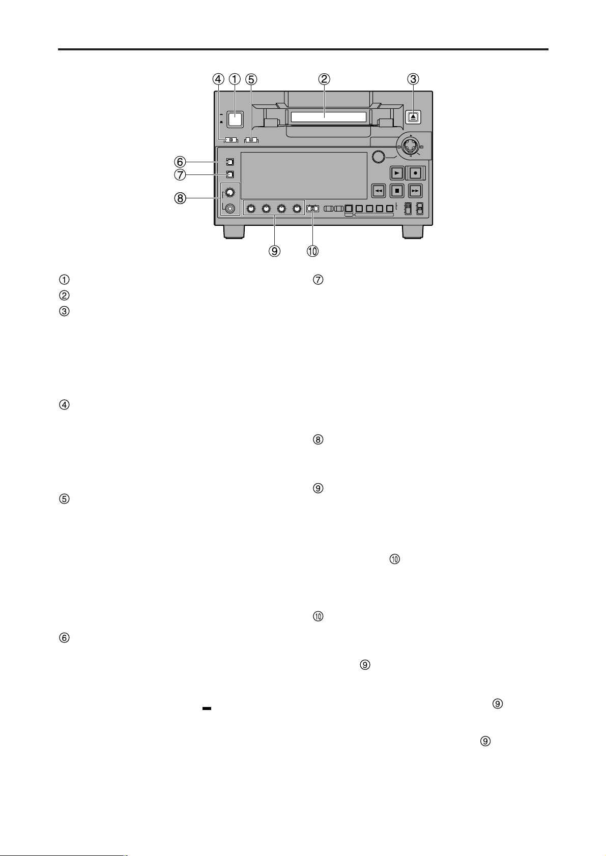
POWER switch
Cassette insertion slot
EJECT button
When this button is pressed, the tape is unloaded and
the cassette is ejected automatically a few seconds
later.
When CTL display has been selected for the counter
display, the display is reset.
EJECT button operation can be enabled or disabled
with setup menu No. 115 (EJECT SW INH).
CONTROL switch
This is selected to control the unit from an external
source using the REMOTE connector.
REMOTE: Set to this position to control the unit using
the 9-pin REMOTE connector and IEEE
1394 AV/C commands.
LOCAL : Set to this position to control the unit using
the controls on the unit's operation panel.
REC INHIBIT switch
This switch is used to enable or disable recording on
the cassette tape.
ON:
Recording on the cassette tape is disabled
(inhibited).
In this state, the REC INH lamp lights on the display
panel.
OFF:
Recording on the cassette tape is enabled so long
as the accidental erasure prevention mechanism on
the cassette tape is set to enable recording.
METER (FULL/FINE) selector button
This button is used to select the scale display for the
audio level meter.
FULL mode : The standard scale (– ∞ to 0 dB) is
selected.
FINE mode : The scale in 0.5 dB increments is
selected. The position indicates
the standard level of –20 dB (–18 dB).
(See page 11)
MONITOR SEL button
This button is used to select the audio signals which
are to be output to the AUDIO MON L and R
connectors.
Each time the button is pressed, the audio signals to
be output to the AUDIO MON L or R connector are
changed in the following sequence.
Which signal is currently selected is displayed by the
lighting of the L or R lamp on the level meter display.
Headphone jack and volume control
When stereo headphones are connected to the
headphone jack, the sound can be monitored using
the headphones during recording or playback.
Audio level control knobs
These knobs are used to adjust the recording and
playback level of the PCM audio signals (CH1, CH2,
CH3 and CH4).
Whether the recording level or playback level is to be
adjusted is selected using the audio level control
selector switch .
Note:
The level of the IEEE 1394 digital input/output audio
signals cannot be adjusted.
Audio level control selector switch
UNITY: At this position, the audio signals are recorded
or played back at a fixed level regardless of
the position of the audio level control knobs
.
REC : At this position, the audio signals are
recorded at the level which has been adjusted
by the audio level control knobs .
PB : At this position, the audio signals are played
back at the level which has been adjusted by
the audio level control knobs .
Note:
It is not possible to set this switch so that both the
recording level and playback level can be adjusted.
When REC is selected, UNITY (fixed level) is set for
the playback level; when PB is selected, UNITY is set
for the recording level.
L : [CH1] [CH3] [CH1] [CH2] [CH3] [CH4]
R : [CH2] [CH4] [CH1] [CH2] [CH3] [CH4]
[CH1+CH2] [CH3+CH4]
[CH1+CH2] [CH3+CH4]
→→→→→
→→
Page 9
– 9 –
Parts and their functions (continued)
Digital Video Cassette Recorder AJ-
SUPER
ON
OFF
TCG
REGEN
PRESET
EXT
INT
COUNTER
PF PF1PF2PF
3DIAG
MENU
PUSH
SHTL/SLOW
TC
PRESET
METER
FULL/FINE
MONITOR SEL
RESET
REC PB
UNITY
INPUT SELECT
VIDEO AUDIO
CH 1 CH 2 CH 3 CH 4
HEADPHONES
SEARCH
EJECT
POWER
REC INHIBITCONTROL
ON
ON
OFF
OFF
LOCAL
REMOTE
RECPLAY
FFREW STOP
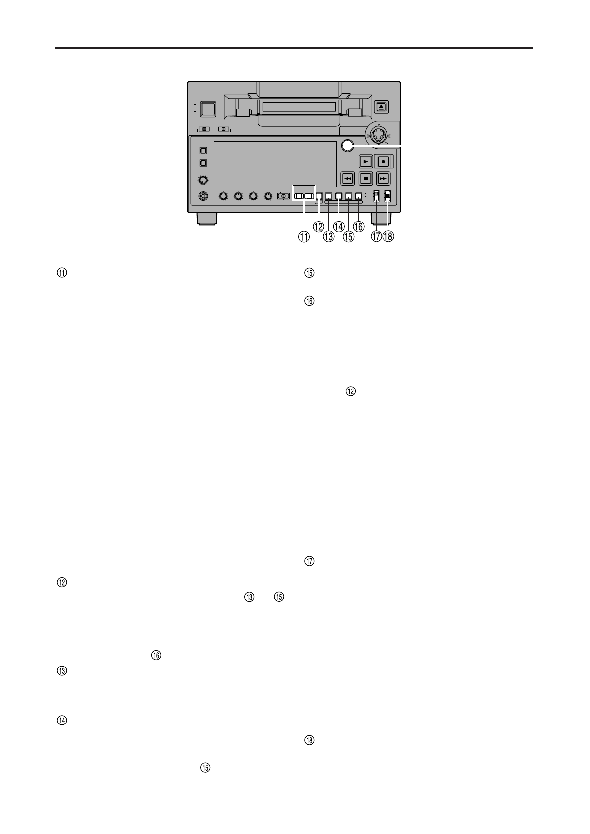
INPUT SELECT buttons
These buttons are used to switch the video and audio
input signals. They can also be used to switch the
input signals to the internal reference signal selected
as the setup menu item No.600 (INT SG) setting.
VIDEO:
Each time the VIDEO button is pressed, the input
video signal selection is switched in the order of [Y PB
PR] →[CMPST] → [SDI] → [1394] → [SG].
• When SG has been selected, the signal is
switched to the internal reference signal selected
as the setup menu item No.600 (INT SG) setting.
AUDIO:
Each time the AUDIO button is pressed, the input
audio signal selection is switched in the order of
[ANALOG] → [SDI] → [1394] → [SG].
Notes:
• It is possible to inhibit the input switch operations
(video and audio) of the INPUT SELECT buttons
using setup menu item No.112 (V IN SEL INH) and
item No.113 (A IN SEL INH).
• The Y PB PR and CMPST settings for the VIDEO
button as well as the ANALOG setting for the
AUDIO button cannot be selected unless the
optional board (AJ-YA93P) has been installed.
• The SDI setting for the VIDEO and AUDIO buttons
cannot be selected unless the optional board (AJYA94G) has been installed.
PF button
When this button is pressed, buttons to
function as the PF1, PF2 and PF3 buttons,
respectively. When it is pressed again before another
button is pressed, these modes are canceled.
When this button is pressed together with the
MENU/DIAG button , the DIAG screen is displayed.
COUNTER/PF1 button
Each time this button is pressed, the counter display
on the display panel changes by one step in the
following sequence: CTL → TC → UB.
RESET/PF2 button
When this button is pressed in the CTL mode, the
counter display is reset to [00:00:00:00].
When it is pressed in the TC/UB mode while holding
down the TC PRESET button , the generator is
reset.
TC PRESET/PF3 button
This button is used to set the TC or UB values.
MENU/DIAG button
When this button is pressed, the setup menus are
displayed on the TV monitor (but only when the VIDEO
MON connector is used), and the setup menu
numbers are displayed on the unit’s display panel.
When it is pressed again, the setup menu settings are
exited, and the original status is restored.
When the button is pressed while holding down the PF
button , the VTR information is displayed. When it
is pressed again, the original display is restored. The
VTR information consists of the WARNING, HOURS
METER, UMID and DIF STATUS 1, 2 information.
The SEARCH button is used to switch the displays
between these kinds of information.
Descriptions of the warnings are displayed on the
WARNING screen. The deck’s serial number, poweron time, drum rotation time, tape travel time, number
of loading times, number of power on/off times, etc.
are displayed on the HOURS METER screen. The
UMID (Unique Material Identifier) information is
displayed on the UMID INFO screen. The IEEE 1394
digital interface information is displayed on the DIF
STATUS 1, 2 screen.
TCG switch
REGEN:
The internal time code generator is synchronized with
the time code which the time code reader has read
from the tape.
The signal that is to be used for regeneration is
selected using setup menu No. 503 (TCG REGEN).
PRESET:
The time code generator can be preset (see page 35)
on the operation panel or by remote control.
EXT:
The external time code which is input from the time
code input connector or video signal VITC, or
IEEE1394 digital input signal is used. Which of the two
is to be set is selected using setup menu No. 505
(EXT TC SEL).
SUPER switch
ON : The time code and other superimposed
information are output to the VIDEO MON
connector.
OFF : No superimposed information is output.
Front panel
SEARCH
button
Page 10
– 10 –
Parts and their functions (continued)
Digital Video Cassette Recorder AJ-
SUPER
ON
OFF
TCG
REGEN
PRESET
EXT
INT
COUNTER
PF PF1PF2PF
3DIAG
MENU
PUSH
SHTL/SLOW
TC
PRESET
METER
FULL/FINE
MONITOR SEL
RESET
REC PB
UNITY
INPUT SELECT
VIDEO AUDIO
CH 1 CH 2 CH 3 CH 4
HEADPHONES
SEARCH
EJECT
POWER
REC INHIBITCONTROL
ON
ON
OFF
OFF
LOCAL
REMOTE
RECPLAY
FFREW STOP
Front panel
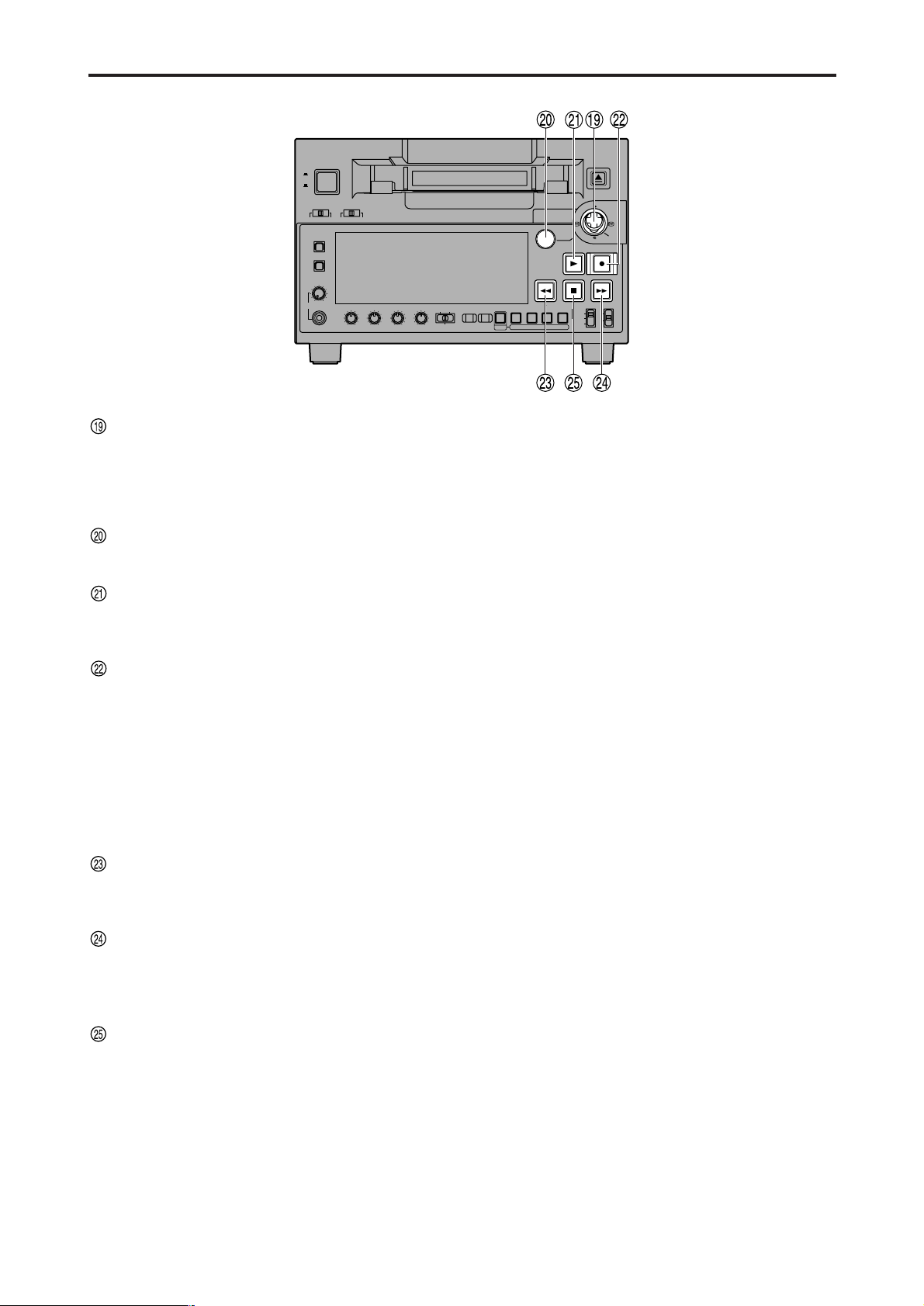
Search stick
This is used for shuttle, slow and other variable-speed
playback. It is also used for the menu settings, etc.
The stick can be moved upward, downward, to the left
or to the right, and it can also be pressed to initiate
operations.
SEARCH button
When this button is pressed, the search mode is
established.
PLAY button
When this button is pressed, playback starts.
When this button and the REC button are pressed
together, recording starts.
REC button
When this button is pressed together with the PLAY
button, recording starts.
When it is pressed during playback, a search, fast
forwarding or rewinding, the E-E mode pictures and
audio signals can be monitored while it is held down.
When it is pressed in the stop mode, the E-E mode
pictures and audio signals can be monitored. (When it
is pressed during playback, the servo will be
disrupted.) When the STOP button is pressed, the
original pictures and sound are restored.
REW button
When this button is pressed, the tape is rewound. The
rewinding speed can be selected using setup menu
No.102 (FF. REW MAX).
FF button
When this button is pressed, the tape is fast
forwarded.
The fast forwarding speed can be selected using setup
menu No.102 (FF. REW MAX).
STOP button
When this button is pressed, the tape stops traveling,
and when TAPE has been selected for the setup menu
item No.122 (STOP EE SEL) setting, the still images
can be monitored.
Even in the stop mode, the drum continues to rotate,
and the tape remains in close contact with the drum.
When the stop mode continues beyond a specific time
period, the unit is automatically set to the standby OFF
mode or STEP FWD mode in order to protect the tape.
(This is set using setup menu item No.400 to 403.)
Immediately after a cassette has been loaded in the
unit, the stop mode is established.
Page 11
– 11 –
Parts and their functions (continued)
Display panel
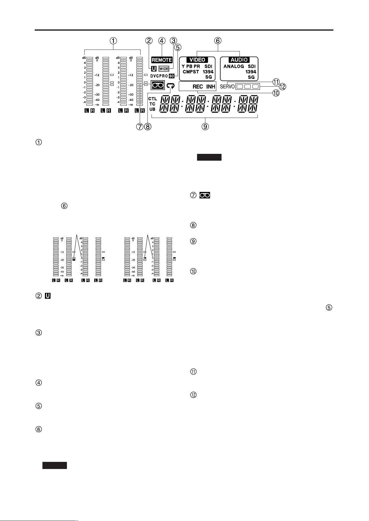
Level meter
This displays the levels of the PCM audio signals for
CH1, CH2, CH3 and CH4.
During recording and when the E-E mode is selected,
it shows the levels of the input audio signals; during
playback, it shows the levels of the output audio
signals.
The audio level display is switched between the FULL
mode and FINE mode using the METER selector
button . (See page 8)
lamp
This lamp lights when UMID information is present on
the input signal in E-E mode.
This lamp lights during tape playback when UMID
information has been recorded on the tape.
WIDE lamp
This lamp lights when 16:9 wide-screen information is
being recorded on a tape.
Recording of wide-screen information can be selected
on setup menu No. 645 (WIDE SELECT).
This lights lamps during tape playback when widescreen information has been recorded on the tape.
REMOTE lamp
This lamp lights when the CONTROL switch has been
set to the REMOTE position.
Format displays
The recording format and the format of the tape
inserted in the unit are displayed here.
INPUT SELECT display area
The characters corresponding to the selected input
signals light up in this area. With the exception of
analog audio signals, flashing appears in this area if
the selected input signals are not available.
Y PB PR : Analog component video signals (option)
CMPST : Analog composite video signals (option)
SDI : Serial digital video signals (option)
VIDEO
1394 : IEEE1394 digital signals
SG : Internal reference signal
ANALOG : Analog audio signals (option)
SDI : Serial digital audio signals (option)
1394 : IEEE1394 digital signals
SG : Internal reference signal
lamp
This lamp lights when a cassette tape is inserted into
the VTR.
In the standby OFF mode, this lamp is flashing.
Repeat lamp
This lights when the repeat play mode has been set.
Counter display
The tape counter, time code, etc. are displayed here.
The type of value displayed is indicated by CTL, TC or
UB.
REC/REC INH lamps
REC:
This lights in the recording mode.
REC INH:
This lights in the recording inhibit mode which is
established either when the REC INHIBIT switch
has been set to ON or the cassette has been set to
the accidental erasure prevention status. Recording
is not possible while this lamp is lighted.
Whether the lamp is to light or flash when the
accidental erasure prevention tab on the cassette
tape has been set to the recording inhibit position
can be selected using setup menu item No.114
(REC INH LAMP).
SERVO lamp
This lights when both the drum servo and capstan
servo are locked.
Channel condition lamps
These lamps light to indicate the error rate status.
(green → white → red)
Green : This lights when the error rates for the video
and audio playback signals are both at
acceptable levels.
White : This lights when the error rate for the video or
audio playback level has increased.
The playback picture and sound remain
unaffected even while this lamp is lighted.
Red : This lights when the error rate for the video or
audio playback level has increased to the
extent that correction or interpolation was
performed.
AUDIO
FULL mode
FINE mode
Reference level
(–20 dB)
FULL mode
FINE mode
Reference level
(–18 dB)
For AJ-SD93P
For AJ-SD93E
Page 12
– 12 –
Parts and their functions (continued)
DVCPRO
/DV
AUDIO MON
AUDIO OUT
VIDEO MON
(SUPER)
750
AUTO
IN
OUT
VIDEO
Y
VIDEO1
SDI
IN
SDI
OUT
VIDEO2
L
CH1CH
2
CH
3
CH
4
CH1CH
2
CH
3
CH
4
Y
R
AC IN
AUDIO IN
P
B
P
R
P
B
P
R
VIDEO OUT
DIGITAL
VIDEO
IN
REF VIDEO IN TIME CODE REMOTE
SIGNAL
GND
9
1
6
5
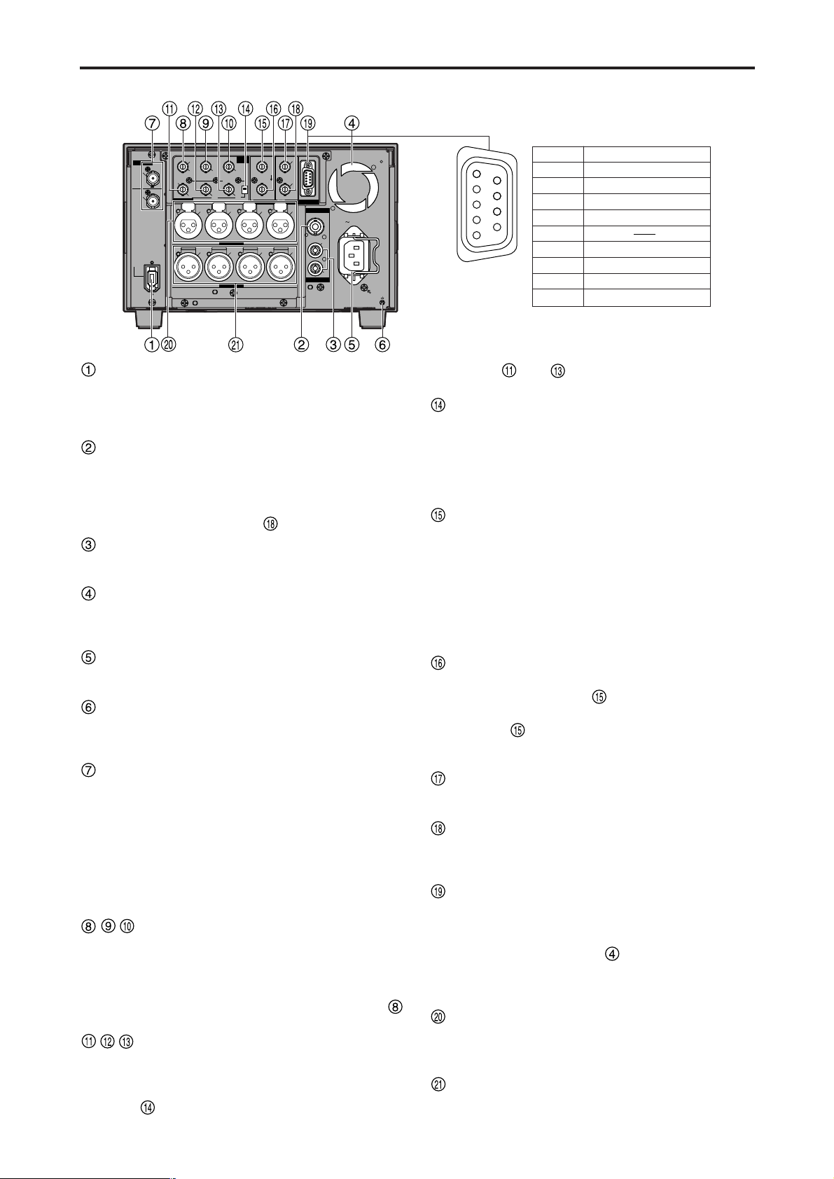
Pin No.
1 Frame Ground
Signal
2 Transmit A
3 Receive B
4 Receive Common
5
6 Transmit Common
7 Transmit B
8 Receive A
9 Frame Ground
Rear panel
IEEE 1394 digital input/output connector
This enables signals to be input and output using the
IEEE 1394 digital interface. Use a 6-pin type of
connector.
Bus power is not supported.
VIDEO MON connector
Analog composite video signals are output from this
connector.
Video signals with information superimposed on them
can be output. To set the superimposing to ON or
OFF, use the SUPER switch on the front panel.
AUDIO MON (L, R) connectors
The playback signal from the PCM audio signals (CH1,
CH2, CH3, CH4) are output from these connectors.
Fan
This fan is used to cool down the VTR.
If, for any reason, the fan stops, “E-10” will appear on
the counter display.
AC IN socket
Connect one end of the power cord supplied to this
socket and the other end to the power outlet.
SIGNAL GND terminal
This is connected to the signal ground terminal on the
component connected to this VTR in order to minimize
noise. It is not a safety ground.
SERIAL DIGITAL COMPONENT AUDIO
VIDEO IN/OUT connectors (option: AJYA94G)
Digital component audio/video signals complying with
the SMPTE 259M-C standard are input to and output
from these connectors.
Note:
The digital audio signals to be input must be
synchronized with the video input signals. Otherwise,
noise will be generated in the audio output signals.
ANALOG VIDEO IN connectors
(option: AJ-YA93P)
Analog component video signals are supplied to these
connectors when the INPUT SELECT button on the
front panel is set to Y PB PR. Analog composite video
signals are supplied using the VIDEO/Y connector
when the button is set to CMPST.
ANALOG VIDEO OUT connectors
(option: AJ-YA93P)
Analog component video signals are output from these
connectors when the ANALOG VIDEO OUT selector
switch has been set to the Y PB PR side (bottom
position). Analog composite video signals are output
from the and connectors when the switch has
been set to the VIDEO1/VIDEO2 side (top position).
ANALOG VIDEO OUT selector switch
(option: AJ-YA93P)
Set this switch to the Y PB PR side (bottom position)
when the ANALOG VIDEO OUT connectors are used
to output component video signals; set it to the
VIDEO1/VIDEO2 side (top position) when they are
used to output composite video signals.
REF VIDEO IN connector (option: AJ-YA93P)
This is the input connector for the reference video
signal. Input a signal with color burst.
Note:
Since the video or audio output signal may be
disrupted if the reference video signal is not input,
it is recommended that this connector be used by the
system which supplies the reference video signals.
Use a signal where SCH does not fluctuate for the
reference video signal.
REF VIDEO OUT connector (option: AJ-YA93P)
This is the loop-through output connector of the REF
VIDEO IN connector . When a cable is not
connected to this connector, the REF VIDEO IN
connector is automatically terminated by the 75 Ω
resistance. When a cable is connected, the 75 Ω
termination is released.
TIME CODE IN connector (option: AJ-YA93P)
This connector is used for recording the external time
code onto the tape.
TIME CODE OUT connector (option: AJ-YA93P)
The playback time code is output from this connector
during playback. During recording, the time code
generated by the internal time code generator is output.
Remote control connector (option: AJ-YA93P)
This enables the unit to be connected to the external
remote controller for operation from an external source.
Notes:
• Set the CONTROL switch to REMOTE.
• The specifications are based on the RS-422A
interface, and editing-related functions do not work.
In this case, use it as a player.
ANALOG AUDIO IN connectors (option: AJYA93P)
The analog audio signals are input from these
connectors.
ANALOG AUDIO OUT connectors (option: AJYA93P)
The analog audio signals are output from these
connectors.
Page 13
– 13 –
Digital Video Cassette Recorder AJ-
SUPER
ON
OFF
TCG
REGEN
PRESET
EXT
INT
COUNTER
PF PF1PF2PF
3DIAG
MENU
PUSH
SHTL/SLOW
TC
PRESET
METER
FULL/FINE
MONITOR SEL
RESET
REC PB
UNITY
INPUT SELECT
VIDEO AUDIO
CH 1 CH 2 CH 3 CH 4
HEADPHONES
SEARCH
EJECT
POWER
REC INHIBITCONTROL
ON
ON
OFF
OFF
LOCAL
REMOTE
RECPLAY
FFREW STOP
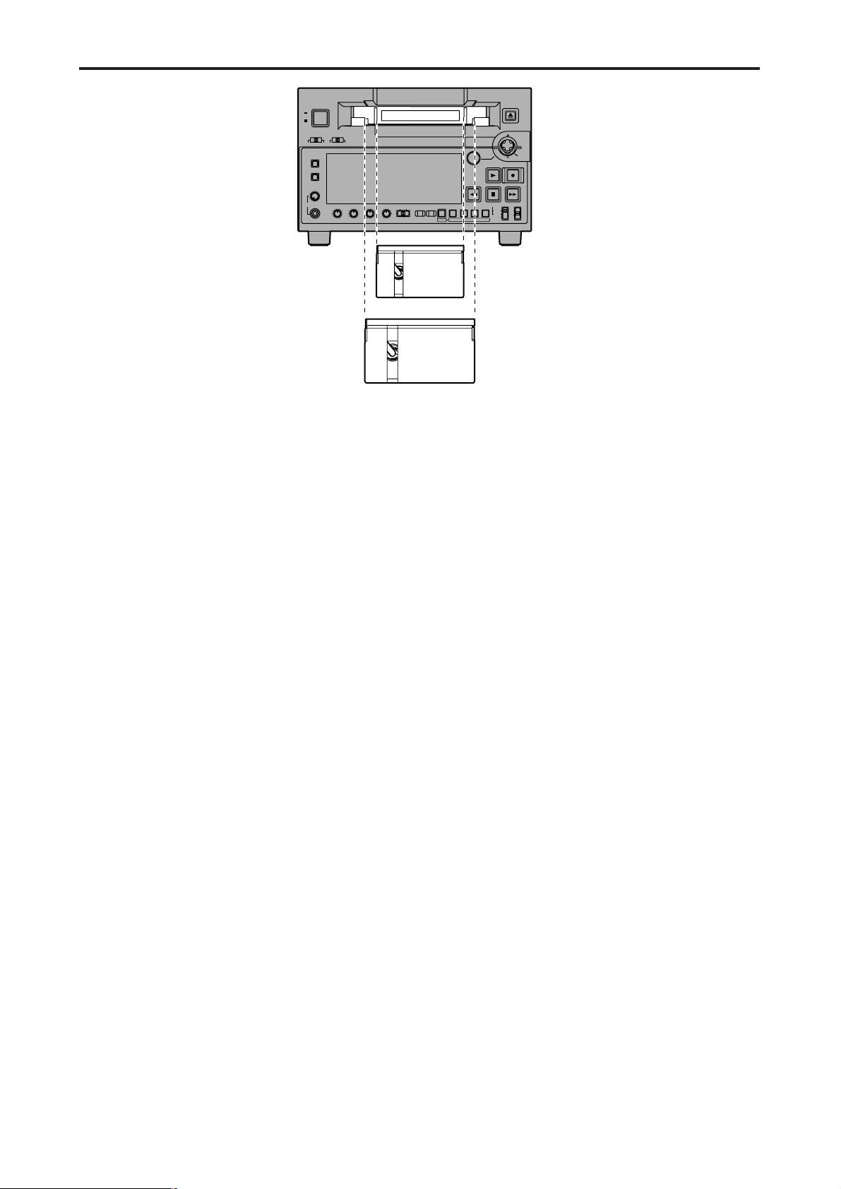
Tapes
Consumer-use DV and DVCAM cassettes
(Standard DV and DVCAM cassettes, mini DV
and DVCAM cassettes)
• Use a cassette adapter (AJ-CS455P) when a mini DV
or DVCAM cassette is to be used.
Note that inserting a mini DV or DVCAM cassette
without the use of a cassette adapter will cause
malfunctioning.
Also note that long-duration mini DV cassettes (80
minutes in the standard mode and 120 minutes in the
LP mode) cannot be used.
• It is not possible to play back tapes which have been
recorded in the LP mode.
• When editing material recorded on a consumer-use
DV or DVCAM cassette, first record the material on a
DVCPRO tape or other tape used by VTRs for
broadcast applications.
• The maximum transport speed of a mini DV or
DVCAM cassette tape is 32x.
• The images may be subject to disturbance during the
slow motion playback of consumer-use DV and
DVCAM cassette tapes.
• From the perspective of protecting consumer-use DV
and DVCAM cassette tapes, minimize the number of
times the tapes are cued up at the same locations as
much as possible.
• When consumer-use DV and DVCAM cassette tapes
are used, the maximum time for STILL TIMER is set
to 10 seconds.
It is recommended that tapes bearing the Panasonic
brand be used as the consumer-use DV tapes.
Align the center of the cassette with the center
of the insertion slot, and press it in gently.
The cassette tape will load automatically.
M cassettes
Tapes capable of up to 33 minutes of recording or
playback
(AJ-5P23MP, AJ-5P33MP)
L cassettes
Tapes capable of up to 92 minutes of recording or
playback
(AJ-5P63LP, AJ-5P92LP)
• Use AJ-5P92LP tapes which have been recorded using
the DVCPRO (25M) format in a VTR that supports 184
minutes of DVCPRO (25M) format recording and
playback.
M cassette size
L cassette size
Page 14
– 14 –
IEEE 1394 digital interface
Precautions for use
• Connect the interface with another device on a 1:1
basis.
• If the E-92 warning (1394 INITIAL ERROR) is
displayed, either re-connect the connecting cable or
turn the VTR’s power off and back on.
• The AV signals may be disrupted when the power of
the connected devices is turned on or off and when
the interface cable is connected or disconnected.
• When the input signals are switched or the mode is
transferred, it may take a few seconds for the system
to stabilize. Proceed with the recording operation only
after the system has stabilized.
• The following situation applies when recording is to
be performed by selecting the IEEE 1394 digital
interface input, and it applies with the signals which
are output by the IEEE 1394 digital interface.
- The audio level control knobs on the front panel do
not work.
- The settings in the 800 series of setup menu items
concerning the vertical blanking period are ignored.
- When playback signals other than regular 1x
speed playback signals have been input, no
guarantees are made for the pictures and sound
which will be recorded or for the EE-type pictures
and sound.
• The following situation applies when the video input
selection has been set as the IEEE 1394 digital
interface.
- The SDI signals, the analog video output signals
and time code output signals become irregular in
the E-E mode. Do not use these signals for
recording purposes. (The teletext signals and other
signals superimposed onto the video output signals
also become irregular.)
• During SLOW/STILL playback, unprocessed video
and audio signals are output as the IEEE 1394 digital
interface output. When these video and audio signals
are monitored using another device, they may differ
from the video and audio signals played back by this
unit.
Be absolutely sure not to defeat the
following safeguards when connecting the
IEEE 1394 cable.
(1) Ensure that the unit and all devices to be
connected are grounded (or connected to a
common ground).
If the equipment cannot be grounded, first turn off the
power of all the connected devices, and then
disconnect and re-connect the IEEE 1394 cable.
(2) When connecting the unit to a device
equipped with a 4-pin connector, connect the
unit’s connector (6-pin type) first.
(3) When making a connection to a PC equipped
with a 6-pin connector, connect the 1394
cable so that it mates properly with the 1394
connector. Bear in mind that if the plug is
inserted the wrong way round, the unit may
be damaged as a result.
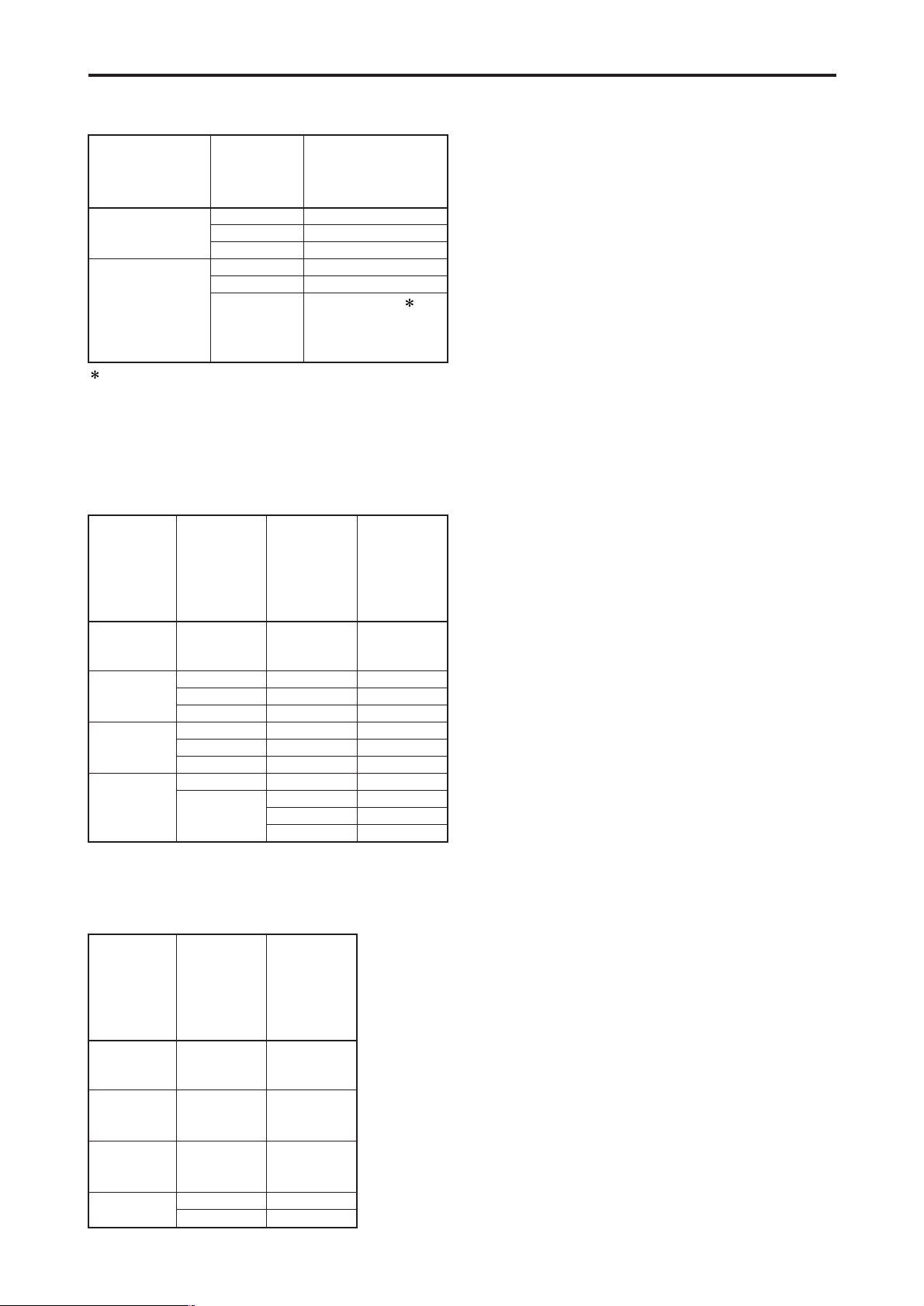
Setup menu
No. 012
(SYS FORMAT)
settings
50M
25M
Input data
DVCPRO50
DVCPRO
DV
DVCPRO50
DVCPRO
DV
Recording format
data
DVCPRO50
Recording not possible
Recording not possible
Recording not possible
DVCPRO
For AJ-SD93P 1:
DVCPRO
For AJ-SD93E:
Recording not possible
Setup menu
No. 881
(DIF TYPE)
setting
During
DVCPRO50
tape playback
During
DVCPRO
tape playback
During
DV/DVCAM
tape playback
During
EJECT or E-E
Setup menu
No. 012
(SYS
FORMAT)
setting
–
–
–
–
–
–
–
50 M
25 M
Mode
DVCPRO50
DVCPRO
DVCPRO
DV
DV
DVCPRO
DV
DVCPRO50
DVCPRO
DVCPRO
DV
Output data
format
–
AUTO
DVCPRO
DV
AUTO
DVCPRO
DV
–
AUTO
DVCPRO
DV
During
DVCPRO50
tape playback
During
DVCPRO
tape playback
During
DV/DVCAM
tape playback
During
EJECT or E-E
Setup menu
No. 012
(SYS
FORMAT)
setting
–
–
–
50 M
25 M
Mode
DVCPRO50
DVCPRO
DV
DVCPRO50
DVCPRO
Output data
format
The recording format for IEEE 1394 digital input data is
determined based on the table below.
1 If the audio of the input data is 32 kHz/4CH, CH1/CH2
and CH3/CH4 can be selected in setup menu No. 889
(DIF AUD IN).
For AJ-SD93P:
The format for IEEE 1394 digital output data is determined
based on the setup menu No. 881 (DIF TYPE) setting and
playback tape (mode).
For AJ-SD93E:
The format for IEEE 1394 digital output data is determined
based on the playback tape (mode).
Page 15

– 15 –
Search stick
(1) Press the SEARCH button to activate the
search stick.
When STICK has been selected as the setup menu
item No.100 (SEARCH ENA) setting, the search stick
will be activated without pressing the SEARCH button.
(2) Press the search stick to switch between the
SHTL mode and SLOW mode.
(3) When the search stick is inclined toward the
right, the tape can be played back in the
forward direction at a variable speed based
on the angle that the stick is inclined. When
the stick is inclined toward the left, the tape
is played back in the reverse direction.
• SHTL mode:
The maximum speed which is established when the
search stick has been inclined at the maximum angle
corresponds to the speed which has been set by
setup menu item No.101 (SHTL MAX).
• SLOW mode:
The speed ranges from -1.0x to +1.0x.
(4) When the search stick is inclined upward, the
tape travels in 1-frame increments in the
forward direction; when it is inclined
downward, it travels in 1-frame increments in
the reverse direction.
Slow playback is performed if the stick is
held at the top or bottom position.
PF (Programmable Function)
(1) Press the MENU button, and open the setup
menu.
(2) Incline the search stick upward or downward
to select the PF number item (A04-A06) to be
registered.
(3) When the search stick is pressed, a list of
items which can be set is displayed.
(4) Incline the search stick upward or downward
to select the item.
Registering the items in the PF buttons
(1) When the PF button is pressed, the
registered items are displayed on the monitor
screen which is output from the VIDEO MON
connector.
(2) Press the PF1, PF2 or PF3 button that
corresponds to the item whose setting is to
be changed. Each time the button is
pressed, the setting is updated in sequence.
(3) When the PF button is pressed again, the
regular display is restored. If no operations
are made, the display is also restored
automatically after five seconds elapse.
Performing operations using the PF buttons
Three setup menu items can be registered in the PF buttons, and these buttons can then be used to change the setup
menu settings by a simple operating procedure.
SETUP-MENU
<USER1>
A02
A04
A05
A06
END
P. ON LOAD
PF1 ASSIGN
PF2 ASSIGN
PF3 ASSIGN
OFF
012
513
---
NO .A04-
MENU
PF1: SYS FORMAT 50M
PF2: INT SG CB75
PF3: ------------------ --------
SETUP-MENU MENU
<USER1>
A04 PF1 ASSIGN - --
--- N O ASSIGN
001 LOCAL ENA
002 TAPE TIMER
003 REMAIN SEL
008 DISPLAY SEL
009 CHARA H-POS
010 CHARA V-POS
SETUP-MENU
NO .A04-
(5) When the search stick is pressed, the regular
menu display screen is restored.
When the MENU button is pressed, a
confirmation screen appears. Press the PLAY
button to set.
Digital Video Cassette Recorder AJ-
SUPER
ON
OFF
TCG
REGEN
PRESET
EXT
INT
COUNTER
PF PF1PF2PF
3 DIAG
MENU
PUSH
SHTL/SLOW
TC
PRESET
METER
FULL/FINE
MONITOR SEL
RESET
REC PB
UNITY
INPUT SELECT
VIDEO AUDIO
CH 1 CH 2 CH 3 CH 4
HEADPHONES
SEARCH
EJECT
POWER
REC INHIBITCONTROL
ON
ON
OFF
OFF
LOCAL
REMOTE
RECPLAY
FFREW STOP
(1)
(2)
(4)
(3)
(4)
(3)
• If the SEARCH button is pressed while the search
stick is pressed to one side, the current speed is
maintained even if the search stick is released.
Pressing the STOP, PLAY, or other operation buttons
cancels the fixed speed operation.
tte Recorder AJ-
PUSH
SHTL/SLOW
SEARCH
RECPLAY
Page 16

– 16 –
Repeat playback
Setting the BEGIN and END points
(1) Press the MENU button.
(2) Select menu item No.161 (CTL(TC)BGN) or
No.162 (END), and incline the search stick to
the left or right.
By operating the search stick, the user can choose
whether or not to set the BEGIN and END points.
“--:--:--:--” appears on the display when the points are
not set. If repeat playback is initiated in this state, the
tape start will serve as the BEGIN point, and the tape
end will serve as the END point.
(3) Press the search stick while the setting is
displayed. The changed digits flash on the
display.
(4) Select TC or CTL using the COUNTER button.
(5) Incline the search stick to the left or right,
and select the digits to change (flashing).
The frame digits cannot be selected. “00” is
always displayed for these digits.
When the search stick is now inclined upward
or downward, the value of the digits changes.
The counter display is reset to 00:00:00:00 when the
RESET button is pressed.
(6) After the settings have been completed,
press the search stick.
(7) Press the MENU button.
A confirmation screen now appears. The
settings are stored in the memory when the
PLAY button is pressed.
Setting the repeat playback mode
(1) Press the MENU button.
(2) Select menu item No.160 (MEMORY MODE),
and select the repeat playback mode.
(3) Press the MENU button.
A confirmation screen now appears. The
settings are stored in the memory if the PLAY
button is now pressed.
Notes:
• The picture quality deteriorates when repeat playback
is initiated for the same tape over and over again. As
a general rule of thumb, replace the tape with a new
one after playing back the tape for about 100 times.
• The output images to be displayed while the tape is
being rewound to the BEGIN point in the repeat
playback mode can be set using menu item No.163
(REPT MODE).
If FREEZE is selected as the REPT MODE setting
and the tape end has been set as the END point, the
playback image will not be frozen properly. Set the
END point at a place on the tape where images have
been recorded.
• If the counter display mode (TC or CTL), which was
established when menu item No.161 (CTL(TC)BGN)
and No.162 (END) were set, is different from the
counter display mode (TC or CTL) in which repeat
playback is to be initiated, the repeat lamp flashes,
and the repeat playback operation cannot be
performed.
Item setting Description of operation
OFF Normal operation
M-STOP
When the tape is fast forwarded or
rewound, it stops near the BEGIN
point.
REPT1
When the tape is played as far as
the END point, it is rewound to the
BEGIN point where it stops.
CONT
When the tape is played as far as
the END point, it is rewound to the
BEGIN point and played, and this
sequence of operations is repeated.
Page 17

– 17 –
Setup (initial settings)
The unit’s main settings are performed while making selections using a menu-driven system.
When a TV monitor is connected to the VIDEO MON connector on the unit’s rear panel, the setup menus will appear on
the TV monitor.
Digital Video Cassette Recorder AJ-
SUPER
ON
OFF
TCG
REGEN
PRESET
EXT
INT
COUNTER
PF PF1PF2PF
3DIAG
MENU
PUSH
SHTL/SLOW
TC
PRESET
METER
FULL/FINE
MONITOR SEL
RESET
REC PB
UNITY
INPUT SELECT
VIDEO AUDIO
CH 1 CH 2 CH 3 CH 4
HEADPHONES
SEARCH
EJECT
POWER
REC INHIBITCONTROL
ON
ON
OFF
OFF
LOCAL
REMOTE
RECPLAY
FFREW STOP
(1) (5)
(2) (3)
Changing the settings
(1) Press the MENU button.
The setup menu screen appears on the TV monitor,
and the setup menu item number appears on the
counter display.
When the FF button is pressed for about 1.5 seconds,
the name of the setup menu item is displayed on the
counter display. When the same button is pressed
again for about 1.5 seconds, the original item No.
display is restored.
(If a setup was performed previously, the screen on
which the last change was made is displayed.)
(2) Incline the search stick upward or downward
to select the item to be set.
The cursor ( ) on the menu screen moves, and the
item number on the display flashes.
• When the FF or REW button is pressed while holding
down the PLAY button, what is on the display is
replaced with the next or previous major item.
(3) Incline the search stick to the left or right at
the position where the change is to be made.
The setting is now changed.
To return what has been established as the setting to
the factory setting, press the RESET button while
holding down the SEARCH button.
(4) If there is another item to be changed, repeat
steps (2) to (3).
(5) Press the MENU button.
• If none of the settings have been changed, the menu
screen display is cleared.
• If a setting has been changed, a confirmation screen
appears.
• To activate the change in the setting, press the PLAY
button.
• To cancel the change in the setting, press the STOP
button.
• To return what has been established as the setting to
the factory setting, press the RESET button while the
menu is displayed. A confirmation screen now
appears, and if the PLAY button is pressed in this
status, the factory setting is restored.
Notes:
•
If the RESET button is pressed to restore the factory
settings, only the user files currently in use are
restored. The other user files remain unaffected.
• The changes made to the SYSTEM menu contents
are recorded also by pressing the MENU button to
close the menu screen.
Page 18

– 18 –
Setup menus
Changing the file
(1) Press the MENU button.
(2) When the FF button is pressed while holding
down the PF button, the next user file is
selected; conversely, when the REW button
is pressed while holding down the PF button,
the previous user file is selected.
Setting and releasing the lock mode
The lock mode can be set to protect the system file and
user file (USER2 to USER5) settings. Once the lock
mode is set, no further changes can be made to the
settings.
Setting and releasing the lock mode can be set for the
system file by using setup menu No. 30 (MENU LOCK)
and for the user files by using setup menu No. A03
(MENU LOCK).
(1) Press the MENU button.
(2) Press the REW button or FF button while
holding down the PF button to select the file
for which the lock mode is to be set or
released.
(3) Operate the search stick to move the cursor
( ) on the menu screen to item No.30 (MENU
LOCK) for the system file or to item No.A03
(MENU LOCK) for a user file.
(4) Press the SEARCH button, and use the
search stick to select whether the lock mode
is to be set or released.
To set the lock mode:
Select 0001 (ON) as the setting.
To release the lock mode:
Select 0000 (OFF) as the setting.
When the lock mode has been set, LOCKED flashes
on the menu screen. The counter display stops
flashing and remains lighted.
(5) Press the MENU button.
A confirmation screen now appears.
(6) When the PLAY button is pressed, what has
been set is stored in the memory.
Notes:
•
The lock mode cannot be set for the USER1 file.
• Once set to the lock mode, a file cannot be reset to
the factory settings even by pressing the RESET
button.
(3) Decide on the user file to be used in the step
(2) operation, and press the MENU button.
A confirmation screen now appears.
(4) When the PLAY button is pressed, what has
been set is stored in the memory.
SYSTEM
USER 1
USER 2
USER 3
USER 4
USER 5
FFFFREW
REW
FF REW
FF REW
FF REW
FF REW
User files
Each user file contains the
following items.
• BASIC
• OPERATION
• INTERFACE
• TAPE PROTECT
• TIME CODE
• VIDEO
• AUDIO
• V BLANK
• DIF
• MENU
This VTR can hold five user files, each of which has its own specific menu settings, and one of these files can be
selected for use.
Page 19

– 19 –
Setup menus (continued)
Loading user files
The contents of the USER2, USER3, USER4 or
USER5 file can be copied (loaded) into the USER1 file.
Also, the contents of the USER1 file can be copied
(saved) into the USER2, USER3, USER4 or USER5
file.
(1) Press the MENU button.
(2) Press the REW button or FF button while
holding down the PF button to select the
USER1 file.
(3) Operate the search stick, and move the
cursor ( ) on the menu screen to item
No.A00 (LOAD).
USER 1 USER 2
USER 3
USER 4
USER 5
Load/save
Lock mode can be
set
Lock mode can be
set
Lock mode can be
set
Lock mode can be
set
Load/save
Load/save
Load/save
SETUP-MENU
<USER1>
804
A00
A01
A02
END
BLANK LINE
LOAD
SAVE
P. ON LOAD
BLANK
USER2
USER2
OFF
NO .A00-0000
MENU
SETUP-MENU
<USER1>
804
A00
A01
A02
END
BLANK LINE
LOAD
SAVE
P. ON LOAD
BLANK
USER2
USER2
OFF
NO .A00-0000
MENU
SETUP-MENU
USER2 USER1 OK?
YES<PLAY>/NO<STOP>
LOAD
(4) Press the search stick, and incline it to the
left or right to select the user file whose
contents are to be loaded into USER1.
(5) Press the search stick.
The following message appears on the menu screen
and counter display.
Menu screen
Counter display
The number of the user file selected in step (4) is
displayed at .
(6) Press the PLAY button
The settings of the user file selected in step (4) are
loaded, and the USER1 menu display appears. If the
STOP button is pressed instead, the settings are not
changed, and the USER1 menu display appears.
(7) Press the MENU button.
A confirmation screen now appears.
When the PLAY button is pressed, the USER1 settings
are stored in the memory. If the settings are not to be
stored in the memory, press the STOP button instead.
Saving user files
(1) Press the MENU button.
(2) Press the REW button or FF button while
holding down the PF button to select the
USER1 file.
(3) Operate the search stick, and move the
cursor ( ) on the menu screen to item
No.A01 (SAVE).
(4) Press the search stick, and incline it to the
left or right to select the user file in which the
contents of USER1 are to be saved.
Those user files which have been set to the lock mode
do not appear on the display. If all the user files have
been set to the lock mode, the “LOCKED” display
appears, and the contents of USER1 cannot be saved
into any of the user files.
(5) Press the search stick.
The following message appears on the menu screen
and counter display.
Menu screen
SETUP-MENU
USER1 USER2 OK?
YES<PLAY>/NO<STOP>
SAVE
Counter display
The number of the user file selected in step (4) is
displayed at .
(6) Press the PLAY button
The settings of USER1 are saved in the user file
selected in step (4) and stored in the memory. If the
STOP button is pressed instead, the settings are not
changed, and the USER1 menu display appears.
(7) Press the MENU button.
The regular display is restored.
Automatically recalling a user file when
turning on the power
If the user file to be loaded is selected in advance
using setup menu No. A02 (P.ON LOAD), the file will
be automatically loaded into USER1 when the power is
turned on.
Page 20

– 20 –
Setup menus (continued)
SYSTEM menu
No./Item Description
13
SYS H
System phase adjustment: 74 ns steps
–: Advanced, +: Delayed
Note:
If setting operation is
performed, the setting
value does not return to
factory (default) setting.
0000 –128
::
0108
0
::
0216 127
11
SYS SC
System phase adjustment:
Variable range ±180 °
–: Advanced, +: Delayed
Note:
If setting operation is
performed, the setting
value does not return to
factory (default) setting.
0000 –128
::
0128
0
::
0255 127
14
SCH COARSE
SCH phase adjustment: 90 ° units
(The SC phase changes but the H phase does not change.)
–: Advanced, +: Delayed
0000 0
0001 90
0002 180
0003 270
15
SCH FINE
SCH phase adjustment:
Total variable range: ±45 ° or more
(The SC phase changes but the H phase does not change.)
–: Advanced, +: Delayed
0000 –32
::
0032
0
::
0064 32
The underlined items indicates the initial setting.
No./Item Description
18
SYS H
OFFSET
System phase adjustment.
0000 –3: –13.4 µsec
0001 –2: –8.96 µsec
0002 –1: –4.52 µsec
0003
0 : 0 sec
0004 1 : +4.52 µsec
0005 2 : +8.96 µsec
0006 3 : +13.4 µsec
Note:
If setting operation is performed, the
setting value does not return to factory
(default) setting.
22
VIDEO LEVEL
This sets the video level.
Max. variable range: ±3 dB
0000 –128
::
0128
0
::
0255 127
24
(For AJ-SD93P)
HUE
(For AJ-SD93E)
CHROMA
PHASE
This sets the hue (chroma phase).
Max. variable range: ±30 °
0000 –128
::
0128
0
::
0255 127
25
CHROMA
LEVEL
This sets the chroma level.
Max. variable range: ±3 dB
0000 –128
::
0128
0
::
0255 127
23
(For AJ-SD93P)
SET UP LEVEL
(For AJ-SD93E)
BLACK LEVEL
This sets the setup (black) level.
Max. variable range: 14 IRE (100 mV)
0000 –128
::
0128
0
::
0255 127
16
AV PHASE
This adjusts the audio output phase
with respect to the video output:
20.8 µs steps
–: The audio output phase is advanced
with respect to the video output.
+: The audio output phase is delayed
with respect to the video output.
0000 –128
::
0128
0
::
0255 127
30
MENU LOCK
This selects whether the system file
lock mode is to be engaged or released.
0000
OFF : The lock is released (file
data can be changed).
0001 ON : The lock is engaged (file
data cannot be changed).
YA93P
YA93P
YA93P
YA93P
YA94G
YA94G
YA93P
YA93P
YA94G
YA93P
YA94G
YA93P
YA94G
YA93P
YA94G
YA93P
YA94G
This appears only when the optional board
AJ-YA93P has been installed.
This appears only when the optional board
AJ-YA94G has been installed.
YA93P
YA93P
Page 21

– 21 –
No./Item Description
008
DISPLAY SEL
This selects what information is to
be provided by the time code and
other super displays output to the
VIDEO MON connector.
0000 TIME : Data only.
(The data indicates the value for
whichever of CTL, TC or UB
currently selected by the COUNTER
button.)
0001
T&STA :
Data and operation status.
0002 T&S&M :
Data, operation status and mode.
0003 T&RT : Data and REC TIME
0004 T&YMD :
Data and REC DATE
(year/month/day)
0005 T&MDY :
Data and REC DATE
(month/day/year)
0006 T&DMY :
Data and REC DATE
(day/month/year)
0007 T&UB :
Data and user bit.
However, when UB has been
selected with the COUNTER button,
the time code is displayed after the
user bit.
0008 T&CTL :
Data and CTL data.
However, when CTL has been
selected with the COUNTER button,
the time code is displayed after the
CTL data.
0009 T&T :
The data and time code recorded in
the VAUX area are displayed.
0010 VITC:
The time code and user bit recorded
in the VAUX area are displayed.
Notes:
• Mode display:
DVCPRO 50 (50 Mbps) =
DVCPRO_50,
DVCPRO (25 Mbps) = DVCPRO,
DV = DV, DVCAM = DVCAM
• An error message appears if a
warning or error has occurred when
“T&S&M” has been selected as this
setting.
•
REC TIME and REC DATE are
displayed during DV/DVCAM, playback
only. With the DVCPRO50 (50 Mbps) or
DVCPRO (25 Mbps) format, the
operating mode is
displayed.
No./Item Description
001
LOCAL ENA
This selects the buttons which can
be operated on the front panel when
the CONTROL switch has been set
to REMOTE.
0000 DIS :
No buttons can be operated.
0001
ST&EJ :
Only the STOP and EJECT buttons
can be operated.
0002 ENA :
All buttons can be operated.
002
TAPE TIMER
This selects the 12 or 24 hour display
for the CTL counter.
0000 ±12h : 12 hour display
0001 24h : 24 hour display
003
REMAIN SEL
This selects whether the remaining
tape time and total tape length are
to be displayed in the
superimposed display of the VIDEO
MON connector signals.
0000 OFF: No display.
0001
2L
:
The remaining tape time is
displayed on the second line.
0002 1L :
The remaining tape time is
displayed on the first line.
0003 R/TTL :
The remaining tape time is
displayed on the first line, and the
total tape length is displayed in the
second line.
Notes:
• When “2L” is selected, the remaining
tape time is not displayed if “TIME” or
“VITC” has been selected as the
setup menu item No.008 (DISPLAY
SEL) setting.
• When “R/TTL” is selected, the total
tape length is not displayed if “TIME”
or “VITC” has been selected as the
setup menu item No.008 (DISPLAY
SEL) setting.
Setup menus (continued)
USER menu <BASIC>
The underlined items indicates the initial setting.
Page 22

– 22 –
Setup menus (continued)
USER menu <BASIC>
The underlined items indicates the initial setting.
No./Item Description
009
CHARA H-POS
This sets the position of the characters
on the horizontal plane for the time
code and other super displays output to
the VIDEO MON connector.
Note:
Press the search stick, then you can
set the position of the characters by
inclining it up or down or to the left or
right.
0000 0
::
0004
4
::
0016 16
010
CHARA V-POS
This sets the position of the characters
on the vertical plane for the time code
and other super displays output to the
VIDEO MON connector.
Notes:
• Press the search stick, then you can
set the position of the characters by
inclining it up or down or to the left or
right.
• When the DISPLAY SEL status
causes characters to extend beyond
the edges of the screen, the setting
value is changed but the characters
are automatically displayed at a
position on the screen where they will
not extend.
(For AJ-SD93E)
0000 0
::
0023
23
::
0028 28
(For AJ-SD93P)
0000 0
::
0018
18
::
0022 22
011
CHARA TYPE
This selects the display type for the
super display output to the VIDEO
MON connector as well as for displays
such as the setting menu, etc.
0000 WHITE :
White characters against a black
background.
0001 W/OUT :
White characters with a black
border.
No./Item Description
012
SYS FORMAT
This sets the VTR’s recording and
playback format.
0000
50M :
DVCPRO50 (50 Mbps) is selected.
0001 25M :
DVCPRO (25 Mbps) is selected.
Note:
The format complies with the setting of
this menu item when the tape is
ejected.
017
CHARA SIZE
This selects the size of the
characters for the superimposed
display output from the VIDEO MON
connector.
0000
NORMAL : Standard size
0001 LARGE :
4 times larger than the standard
size
Note:
When LARGE has been selected, only
time data is displayed, regardless of
the setup menu No.008 (DISPLAY
SEL) setting.
013
PB FORMAT
This sets the format in which the
tape is to be played back.
0000 MANUAL :
The format complies with the setting
of setup menu No. 012 (SYS
FORMAT) when a DVCPRO
cassette is inserted. The format
complies to the format recorded on
the tape when a DV or DVCAM
cassette is inserted.
0001
AUTO :
The format complies with the format
recorded on the tape.
Note:
When AUTO has been selected, the
picture and sound may be disturbed
until the format is detected after a tape
is loaded.
Page 23

– 23 –
Setup menus (continued)
USER menu <OPERATION>
The underlined items indicates the initial setting.
No./Item Description
100
SEARCH ENA
This sets the method used to transfer
to the search mode (stick operation).
0000 STICK :
Operation transfers to the search
mode when the SEARCH button is
pressed or the stick is operated.
0001 KEY :
Operation is not transferred to the
search mode unless the SEARCH
button is pressed.
101
SHTL MAX
This sets the maximum speed for
shuttle
0000 x8.4 : 8.4x normal speed
0001
x16
: 16x normal speed
0002 x32 : 32x normal speed
104
REF ALARM
This selects whether to warn the
operator when the REF. VIDEO
signal has not been connected.
0000 OFF :
Warning is not given.
0001
ON
:
Warning is given by the flashing
STOP lamp.
Note:
Video and audio output may be disturbed
when the reference video signal is not
input, so it is recommended that a
system which inputs the reference video
signal be used.
102
FF. REW MAX
This sets the maximum speed for
FF and REW operations.
0000 x16 : 16(32)x normal speed
0001 x32 : 32(60)x normal speed
0002
x50 : 50(100)x normal speed
Notes:
• The speeds given in the parentheses
apply in the DVCPRO (25 Mbps), DV
and DVCAM mode.
• With mini DV or mini DVCAM cassette,
the maximum speed is set to 32x
regardless of this item’s settings.
107
PLAY DELAY
This set the play delay time in frame
increments.
0000
0
::
0015 15
108
CAP.LOCK
This selects the CAPSTAN LOCK
mode.
Note:
Color framing for the VIDEO MON
connector output is not guaranteed.
(For AJ-SD93E)
0000 2F : 2F mode
0001 4F : 4F mode
0002 8F : 8F mode
(For AJ-SD93P)
0000 2F : 2F mode
0001 4F : 4F mode
No./Item Description
111
FRZ MODE
SEL
This selects the output picture in the
STANDBY OFF (HALF LOADING) and
EJECT modes.
0000 DIS:
The video output is muted.
0001 STB OFF:
When the STANDBY OFF (HALF
LOADING) mode is established, the
picture being played back at the time is
frozen and output.
0002 SOF&EJ:
When the STANDBY OFF (HALF
LOADING) or EJECT mode is
established, the picture being played
back at the time is frozen and output.
Notes:
•
The freeze status complies with the setup
menu item No.605 (FREEZE SEL) setting.
•The playback screen freezes only
when setup menu No. 122 (STOP EE
SEL) is set to STOP.
•
In the EJECT mode, the freeze image is
output only when BLACK or GRAY is
selected as the setup menu item No.120
(EJECT EE SEL) setting.
109
AUTO REW
This selects whether to rewind the
tape automatically to the tape start
when the tape end is detected.
0000
OFF :
The tape stops at the tape end.
0001 ON :
The tape is rewound to the tape start.
Note:
The tape stops near the BEGIN point
when setup menu No. 160 (MEMORY
MODE) is set to M-STOP.
112
V IN SEL INH
This selects whether video input
switching using the INPUT SELECT
button is to be enabled or disabled.
0000
OFF :
Video input switching using the
INPUT SELECT button is enabled.
0001 ON :
Video input switching using the
INPUT SELECT button is disabled.
0002 REC :
Video input switching using the
INPUT SELECT button after the unit
has been transferred to a recording
(but not editing) mode is disabled.
113
A IN SEL INH
This selects whether audio input
switching using the INPUT SELECT
button is to be enabled or disabled.
0000
OFF :
Audio input switching using the
INPUT SELECT button is enabled.
0001 ON :
Audio input switching using the
INPUT SELECT button is disabled.
0002 REC :
Audio input switching using the
INPUT SELECT button after the unit
has been transferred to a recording
(but not editing) mode is disabled.
YA93P
YA93P
This appears only when the optional board
AJ-YA93P has been installed.
YA93P
Page 24

– 24 –
Setup menus (continued)
The underlined items indicates the initial setting.
USER menu <OPERATION>
No./Item Description No./Item Description
115
EJECT SW
INH
This selects whether to enable or
disable the operation of the EJECT
button on the front panel.
0000
REC :
Operation is disabled while the unit
is in the recording mode.
0001 OFF :
Operation is enabled in all modes.
120
EJECT EE SEL
This selects the modes for the
picture and sound output when the
tape is ejected.
0000
EE : EE mode
0001 BLACK :
The picture turns black, and the
sound is muted.
0002 GRAY :
The picture turns gray, and the
sound is muted.
Note:
The IEEE 1394 digital output video will
be black even if GRAY is selected.
121
F/R EE SEL
This selects whether the EE mode or
playback mode is to be established
during fast forwarding or rewinding.
0000 EE : EE mode
0001 TAPE : Playback mode
122
STOP EE SEL
This select whether the EE mode or
playback mode is to be established
when operation is stopped.
0000
EE
: EE mode
0001 TAPE : Playback mode
Note:
The selection is complied with even in the
standby OFF mode. However, the picture
will turn gray (black for IEEE 1394 digital
output) when TAPE is selected.
160
MEMORY
MODE
This sets the repeat play mode.
0000
OFF :
No repeat play (normal operation)
0001 M-STOP :
The tape stops near the BEGIN point when a
FF or REW operation has been performed.
0002 REPT1 :
During playback, the tape is rewound to the
BEGIN point and stopped when the END
point is reached.
0003 CONT :
During playback, the tape is rewound to the
BEGIN point and then played, and these
steps are repeated when the END point is
reached.
161
CTL BGN
or
TC BGN
This sets the BEGIN point in the
repeat play mode.
Whether TC or CTL is displayed on the counter
when the COUNTER button is pressed is set
here. When there is no setting, --:--:--:-- appears,
and the tape start serves as the BEGIN point.
162
END
This sets the END point in the
repeat play mode.
Whether TC or CTL is displayed on the counter
when the COUNTER button is pressed is set
here. When there is no setting, --:--:--:-- appears,
and the tape end serves as the END point.
163
REPT MODE
This sets the output image when the
tape returns to the BEGIN point in
the repeat play mode.
0000
FREEZE :
The tape returns to the BEGIN point
while the playback image at the
END point remains frozen.
0001 BLACK :
The tape returns to the BEGIN point while
a BLACK picture remains on the screen.
0002 EE_SEL :
The tape returns to the BEGIN point
with an image which is in
compliance with the setup menu
item No.121 (F/R EE SEL) setting.
Note:
If, when FREEZE has been selected, the
END point has been set at the tape end,
the playback image will not be frozen
properly. Set the END point in a range
where pictures have been recorded.
202
ID SEL
This sets the ID information to be
returned to the controller.
0000 OTHER :
0001
DVCPRO :
0002 ORIG :
Notes:
• ID information of any VTR except for
the DVCPRO’s is set in OTHER.
•
The ORIG setting should only be used
when a Panasonic controller (AG-A850
etc. sold separately) is connected.
114
REC INH
LAMP
This selects whether to cause the
REC INH lamp to flash or light up
when the cassette has been set to the
accidental erasure prevention status.
0000 LIGHT : The lamp lights up.
0001 FLASH : The lamp flashes.
Note:
When the REC INHIBIT switch is set to
ON, the REC INH lamp always lights
regardless of the general setting status.
YA93P
USER menu <INTERFACE>
No./Item Description
This appears only when the optional board
AJ-YA93P has been installed.
YA93P
Page 25

– 25 –
Setup menus (continued)
The underlined items indicates the initial setting.
No./Item Description
USER menu <TAPE PROTECT>
No./Item Description
401
SRC
PROTECT
When the time selected as the setup
menu item No. 400 (STILL TIMER)
setting elapses while the unit is in
the search STILL (JOG/SLOW/SHTL)
mode, the unit automatically enters
one of the tape protection modes.
This menu item is for selecting
which tape protection mode the unit
is to enter.
0000
STEP
: STEP FWD
0001 HALF : HALF LOADING
Note:
When STEP FWD is selected, the unit
automatically goes into the STANDBY
OFF (HALF LOADING) mode when
the total time for which the unit is left
standing in the still status reaches 30
minutes (or 1 minute for a DV/DVCAM
tape).
402
DRUM
STDBY
This selects the drum operation in
the STANDBY OFF (HALF
LOADING) mode.
0000 OFF :
The drum stops rotating.
0001
ON :
The drum continues rotating.
403
STOP
PROTECT
When the time selected as the setup
menu item No. 400 (STILL TIMER)
setting elapses while the unit is in
the STOP mode, the unit
automatically enters one of the tape
protection modes. This menu item
is for selecting which tape
protection mode the unit is to enter.
0000 STEP : STEP FWD
0001
HALF : HALF LOADING
Note:
When STEP FWD is selected, the unit
is automatically transferred to the
STANDBY OFF (HALF LOADING)
mode when the total time during which
it has been left standing in the STOP
mode reaches 30 minutes (or 1 minute
for a DV/DVCAM tape).
400
STILL TIMER
This selects the time to be taken until
the unit goes into the tape protection
mode when it is left standing in the stop
or search still (JOG/SLOW/SHTL) mode.
(Unit: s = second, min = minute)
0000 0.5s
0001 5s
0002 10s
0003 20s
0004 30s
0005 40s
0006 50s
0007 1min
0008
2min
Notes:
•
STEP FWD and HALF LOADING are
provided in the tape protection mode.
Either of these can be set for STOP
and SEARCH STILL.
•
The cumulative standby time at the
same tape position increases when
transmitting programs or otherwise
using identical materials repeatedly. In
order to protect the tape, it is
recommended that the shortest
possible setting for the standby time in
the same tape location is used.
• When a DV/DVCAM tape is used,
any setting above 10 seconds will be
treated as 10 seconds.
Page 26

– 26 –
Setup menus (continued)
USER menu <TIME CODE>
The underlined items indicates the initial setting.
No./Item Description
506
BINARY GP
This sets the usage status of the
user bit of the time code generated
by the TCG.
0000
000 :
NOT SPECIFIED (character set not
specified)
0001 001 :
ISO CHARACTER (8 bits character
set based on ISO646, ISO2022)
0002 010 :
UNASSIGNED 1 (undefined)
0003 011 :
UNASSIGNED 2 (undefined)
0004 100 :
UNASSIGNED 3 (undefined)
0005 101 : PAGE/LINE
0006 110 :
UNASSIGNED 4 (undefined)
0007 111 :
UNASSIGNED 5 (undefined)
507
PHASE
CORR
This selects whether to control the
phase correction of the LTC which
is output from the TIME CODE OUT
connector.
0000
OFF :
Phase correction control is not
performed.
0001 ON :
Phase correction control is
performed.
508
TCG CF
FLAG
This selects whether the CF flag of
the TCG is to ON.
0000
OFF : CF flag is OFF.
0001 ON : CF flag is ON.
509
DF MODE
(For AJ-SD93P)
This selects the DF or NDF mode for
CTL and TCG.
0000
DF :
The drop frame mode is used.
0001 NDF :
The non-drop frame mode is used.
Note:
DF/NDF switching is valid only when
the CONTROL switch is set to LOCAL
or the setup menu No. 001 (LOCAL
ENA) is set to ENA.
No./Item Description
500
VITC BLANK
For selecting whether to output the
VITC signal at the positions selected by
setup menu items No. 501 (VITC POS-1)
and No. 502 (VITC POS-2).
0000 BLANK :
VITC signals are not output.
0001
THRU :
VITC signals are output.
501
VITC POS-1
This sets the position where the
VITC signal is to be inserted.
Notes:
•
The same line as the one used for the
setup menu items No. 502 (VITC POS-
2) and No. 662 (UMID POS) setting
cannot be set.
• The default settings are not restored
even if the RESET button is pressed
while holding down the SEARCH
button.
(For AJ-SD93E)
0000 7L
::
0004
11L
::
0015 22L
(For AJ-SD93P)
0000 10L
::
0006
16L
::
0010 20L
502
VITC POS-2
This sets the position where the
VITC signal is to be inserted.
Notes:
•
The same line as the one used for the
setup menu items No. 501 (VITC POS-
1) and No. 662 (UMID POS) setting
cannot be set.
• The default settings are not restored
even if the RESET button is pressed
while holding down the SEARCH
button.
(For AJ-SD93E)
0000 7L
::
0006
13L
::
0015 22L
(For AJ-SD93P)
0000 10L
::
0008
18L
::
0010 20L
503
TCG REGEN
This selects the signal to be
regenerated when the time code
generator (TCG) in the REGEN
mode.
0000
TC&UB :
Both the time code and user bit are
regenerated.
0001 TC :
Only the time code is regenerated.
0002 UB :
Only the user bit is regenerated.
505
EXT TC SEL
This selects the time code to be
used when an external time code is
to be used.
0000
LTC :
The LTC of the TIME CODE IN
connector is used.
0001 VITC :
The VITC of the input video signal
or the timecode of the IEEE 1394
digital input signal is used.
Note:
Operation uses the VITC setting if AJYA93P is not installed.
YA93P
YA93P
This appears only when the optional board
AJ-YA93P has been installed.
YA93P
Page 27

– 27 –
USER menu <TIME CODE>
Setup menus (continued)
The underlined items indicates the initial setting.
No./Item Description
510
TC OUT REF
This is used to switch the phase of
the time code, which is output from
the TIME CODE OUT connector, for
the external LTC input when the
TCG switch is at the EXT position.
0000
V OUT :
Time code is synchronized with
output video signal.
0001 TC_IN :
Time code is synchronized with
external time code input.
511
VITC OUT
This selects how the VITC which is
to be superimposed onto the output
video signal is to be output.
0000
SBC :
During recording:
The input time code, which was
selected by the setup menu No.
505 (EXT TC SEL) setting and
TCG switch, is output as the
VITC.
During playback:
The time code recorded in the
SBC area is output as the VITC.
0001 VAUX :
During recording:
The time code detected from the
input video signal is output as the
VITC.
During playback:
The time code recorded in the
VAUX area is output as the
VITC.
Notes:
• The time code detected from the
input video signal is automatically
recorded in the VAUX area while
pictures are being recorded.
• If Y PB PR, CMPST, or SDI is
selected as the input signal, the VITC
output during recording is a timecode
superimposed on the input signal
regardless of the above setting.
514
VITC GEN
This selects whether or not to
record the internal time code
generator value in the VAUX area.
0000
OFF :
The internal time code generator
value is not recorded in the VAUX
area. When video signals on which
the time code has been recorded
are input, the time code of the input
signals is recorded in the VAUX
area.
0001 ON :
The internal time code generator
value is recorded in the VAUX area.
513
RUN MODE
This sets the operation mode which
is to make the internal time code
generator advance.
0000
REC :
The internal time code generator is
advanced during recording.
0001 FREE :
When the power is on, the internal
time code generator is advanced
regardless of the operation mode.
No./Item Description
SBC (sub code data) area:
This area is separate from the video and audio data area
on the helical track. The time code complying with
SMPTE/EBU standards is stored here. As with the
conventional LTC (linear time code), the time code can be
read even during rewinding or fast forwarding. It can also
be read out when the tape has stopped.
VAUX (video auxiliary data) area:
This area is to be found in the video data area on the
helical track.
The additional information relating to the video data is
stored here.
Note:
The time code and user bit are controlled during tape
playback by the data which has been recorded in the
SBC area. This means that all the data recorded in the
SBC area alone is used as the data which is to be
indicated on the counter display section in the middle of
the front panel or in the superimposed display, or as
the data which is to be transmitted to the editing
controller or other unit.
This appears only when the optional board
AJ-YA93P has been installed.
YA93P
YA93P
Page 28

– 28 –
Setup menus (continued)
The underlined items indicates the initial setting.
USER menu <VIDEO>
No./Item Description
600
INT SG
This selects the internal reference signal.
0001 BB :
The black burst is generated.
0002 CB100 :
100% color bars are generated.
0003
CB75 :
75% color bars are generated.
602
V-MUTE
SEL
This selects whether to mute the
video output signals when a blank
on the tape has been detected
during playback.
0000 N-MUTE : No muting. (Freeze)
0001
LOW RF
:Muting. (Set to gray.)
603
CC (F1)
BLANK
(For AJ-SD93P)
This selects ON or OFF for the closed
caption signal of the first field.
0000 BLANK :
Signal is forcibly blanked.
0001 THRU :Signal is not blanked.
604
CC (F2)
BLANK
(For AJ-SD93P)
This selects ON or OFF for the closed
caption signal of the second field.
0000 BLANK :
Signal is forcibly blanked.
0001 THRU
:Signal is not blanked.
605
FREEZE SEL
This selects the freeze mode for still
pictures.
0000
FIELD : Field freeze.
0001 FRAME : Frame freeze.
Note:
When frame freeze has been selected,
the frame slow status is established
with the slow setting.
609
EDH
This selects whether to
superimpose EDH onto the SDI
output signals.
0000 OFF :
EDH is not superimposed.
0001 ON : EDH is superimposed.
610
PB/PR IN LV
(For AJ-SD93P)
This selects the analog component
input level.
0000 M : M level
0001
B-CAM : ß-CAM level
614
PB/PR OUT
LV
(For AJ-SD93P)
This selects the analog component
output level.
0000 M : M level
0001
B-CAM : ß-CAM level
No./Item Description
YA94G
YA94G
This appears only when the optional board
AJ-YA93P has been installed.
This appears only when the optional board
AJ-YA94G has been installed.
YA93P
622
SETUP 25
(For AJ-SD93P)
For setting 7.5% setup processing
to be performed on input and output
signals in the DVCPRO (25 Mbps)
mode.
When the STOP button is pressed,
operation is transferred to the subscreen, and the setup level is set for
each output. To return from the subscreen, press the STOP button again.
00
CMPST IN
This selects the 7.5% setup processing
for the input composite signal.
0000 THRU :
The signal is recorded in its original
form.
0001 CUT :
The signal is recorded with the
7.5% setup removed.
01
CMPST OUT
This selects the 7.5% setup processing
for the output composite signal.
0000 THRU :
The signal is output in its original
form.
0001 ADD :
The signal is output with the 7.5%
setup added.
Note:
Bear in mind the setting for sub-screen
item No. 03 (CMPNT OUT) of setup
menu item No. 622 (SETUP 25).
02
CMPNT IN
This selects the 7.5% setup processing
for the input component signal.
0000 THRU :
The signal is recorded in its original
form.
0001 CUT :
The signal is recorded with the
7.5% setup removed.
03
CMPNT OUT
This selects the 7.5% setup processing
for the output composite, component
and serial (digital) signal.
0000 THRU :
The signal is output in its original
form.
0001 CUT :
The signal is output with the 7.5%
setup removed.
0002 ADD :
The signal is output with the 7.5%
setup added.
Sub-screen
YA93P
YA93P
YA93P
YA93P
YA94G
YA93P
YA94G
Page 29

– 29 –
660
UMID REC
This selects whether or not to
record the UMID information on the
tape.
0000 OFF :
UMID information is not recorded on
the tape.
0001
ON :
UMID information is recorded on the
tape.
Note:
If 1394 has been selected as the input
signals using the INPUT SELECT
button, UMID will not be recorded even
when it is set to ON unless the input
signal can be detected.
Setup menus (continued)
624
CC REC
(For AJ-SD93P)
For selecting whether to record the
closed caption signals multiplexed
on the input signals on the tape.
0000
OFF :
No closed caption signal is recorded.
0001 ON :
When a closed caption signal is
detected from the selected input
signal, it can be recorded.
Note:
If 1394 signals have been selected as
the input signals using the INPUT
SELECT button, the closed caption
signals which have been multiplexed
onto the input signals will be recorded
on the tape regardless of the setting.
645
WIDE
SELECT
This selects whether or not to record
the wide-screen information on the tape.
0001 WIDE :
The wide-screen information is not
recorded on the tape.
0002
NORMAL
:
The wide-screen information is
recorded on the tape.
Note:
If 1394 has been selected as the input
signals using the INPUT SELECT
button, the wide-screen information on
the input signals will be recorded
regardless of this menu’s setting.
YA93P
YA94G
623
SETUP 50
(For AJ-SD93P)
For setting 7.5% setup processing
to be performed on input and output
signals in the DVCPRO50 (50 Mbps)
mode.
When the STOP button is pressed,
operation is transferred to the subscreen, and the setup level is set for
each output. To return from the subscreen, press the STOP button again.
No./Item Description
00
CMPST IN
This selects the 7.5% setup processing
for the input composite signal.
0000 THRU :
The signal is recorded in its original
form.
0001 CUT :
The signal is recorded with the
7.5% setup removed.
01
CMPST OUT
This selects the 7.5% setup processing
for the output composite signal.
0000 THRU :
The signal is output in its original
form.
0001 ADD :
The signal is output with the 7.5%
setup added.
Note:
Bear in mind the setting for sub-screen
item No. 03 (CMPNT OUT) of setup
menu item No. 623 (SETUP 50).
02
CMPNT IN
This selects the 7.5% setup processing
for the input component signal.
0000 THRU :
The signal is recorded in its original
form.
0001 CUT :
The signal is recorded with the
7.5% setup removed.
03
CMPNT OUT
This selects the 7.5% setup processing
for the output composite, component
and serial (digital) signal.
0000
THRU :
The signal is output in its original
form.
0001 CUT :
The signal is output with the 7.5%
setup removed.
0002 ADD :
The signal is output with the 7.5%
setup added.
Sub-screen
No./Item Description
USER menu <VIDEO>
The underlined items indicates the initial setting.
YA94G
This appears only when the optional board
AJ-YA93P has been installed.
This appears only when the optional board
AJ-YA94G has been installed.
YA93P
YA93P
YA93P
YA94G
YA93P
YA94G
Page 30

– 30 –
Setup menus (continued)
USER menu <VIDEO>
The underlined items indicates the initial setting.
No./Item Description
662
UMID POS
This sets the line on which the
UMID information is to be
superimposed.
Notes:
• The line selected for the setup menu
item No. 501 (VITC POS-1) and No.
502 (VITC POS-2) settings cannot be
selected for this item.
• The default settings are not restored
even if the RESET button is pressed
while holding down the SEARCH
button.
(For AJ-SD93E)
0000 BLANK
0001 8L
::
0010
17L
::
0015 22L
(For AJ-SD93P)
0000 BLANK
0001 12L
::
0006
17L
::
0008 19L
No./Item Description
USER menu <AUDIO>
701
CH1 IN LV
This selects the audio input (CH1)
reference level switching.
0000 4dB
0001
0dB
0002 –20dB
702
CH2 IN LV
This selects the audio input (CH2)
reference level switching.
0000 4dB
0001
0dB
0002 –20dB
703
CH3 IN LV
This selects the audio input (CH3)
reference level switching.
0000 4dB
0001
0dB
0002 –20dB
704
CH4 IN LV
This selects the audio input (CH4)
reference level switching.
0000 4dB
0001
0dB
0002 –20dB
706
CH1 OUT LV
This selects the audio output (CH1)
reference level switching.
0000 4dB
0001
0dB
0002 –20dB
707
CH2 OUT LV
This selects the audio output (CH2)
reference level switching.
0000 4dB
0001
0dB
0002 –20dB
708
CH3 OUT LV
This selects the audio output (CH3)
reference level switching.
0000 4dB
0001
0dB
0002 –20dB
709
CH4 OUT LV
This selects the audio output (CH4)
reference level switching.
0000 4dB
0001
0dB
0002 –20dB
YA93P
YA94G
661
UMID GEN
This selects the basic UMID
information to be recorded on the
tape when ON has been selected as
the setup menu item No. 660 (UMID
REC) setting.
0000 INT :
Newly created basic UMID
information of this unit is always
recorded.
0001
EXT :
The basic UMID information of the
input signals is recorded.
Newly created basic UMID
information of this unit is recorded if
there is no basic UMID information
on the input signals.
Note:
The source pack (of the UMID
information) of the input signal will be
recorded on the tape, regardless of
this menu’s setting.
YA94G
This appears only when the optional board
AJ-YA93P has been installed.
This appears only when the optional board
AJ-YA94G has been installed.
YA93P
YA93P
YA93P
YA93P
YA93P
YA93P
YA93P
YA93P
Page 31

– 31 –
Setup menus (continued)
The underlined items indicates the initial setting.
USER menu <AUDIO>
No./Item Description
722
REC CH1
This selects the input signal to be
recorded on the audio CH1 track.
0000 CH1 :
Audio input CH1 signal.
0001 CH2 :
Audio input CH2 signal.
0002 CH1+2 :
Mixed audio input CH1 and CH2
signal.
723
REC CH2
This selects the input signal to be
recorded on the audio CH2 track.
0000 CH1 :
Audio input CH1 signal.
0001
CH2 :
Audio input CH2 signal.
0002 CH1+2 :
Mixed audio input CH1 and CH2
signal.
724
REC CH3
This selects the input signal to be
recorded on the audio CH3 track.
0000 CH3 :
Audio input CH3 signal.
0001 CH4 :
Audio input CH4 signal.
0002 CH3+4 :
Mixed audio input CH3 and CH4
signal.
725
REC CH4
This selects the input signal to be
recorded on the audio CH4 track.
0000 CH3 :
Audio input CH3 signal.
0001
CH4 :
Audio input CH4 signal.
0002 CH3+4 :
Mixed audio input CH3 and CH4
signal.
No./Item Description
727
PB FADE
This selects the processing method for
the audio edit points (IN point, OUT
point) during playback.
0000 AUTO :
According to the status during
recording.
0001 CUT : Forced CUT
0002 FADE : Forced FADE
728
EMBEDDED
AUD
This selects whether to superimpose
the audio data onto the SDI output.
0000 OFF :
Data is not superimposed.
0001 ON : Data is superimposed.
734
MONI SEL
INH
This selects whether the operation
of the MONITOR SELECT button on
the front panel is to be enabled or
disabled.
0000
OFF : Operation is enabled.
0001 ON : Operation is disabled.
0002 ON1 :
Operation is disabled in the FULL
display mode and enabled only in
the FINE display mode.
750
DV PB ATT
This selects the audio output level
during DV playback.
0000 OFF :
The audio output level is not
attenuated.
0001
ON :
The audio output level is attenuated
(reduced).
751
REC PT
MUTE
This selects whether to mute the
sound where recordings are joined
during DV/DVCAM
0000
OFF
: The sound is not muted.
0001 ON : The sound is muted.
YA93P
YA94G
YA93P
YA94G
YA93P
YA94G
YA93P
YA94G
YA94G
YA94G
This appears only when the optional board
AJ-YA93P has been installed.
This appears only when the optional board
AJ-YA94G has been installed.
YA93P
Page 32

– 32 –
13
10
Setup menus (continued)
USER menu <V BLANK>
The underlined items indicates the initial setting.
No./Item Description
802
TELETEXT
SEL
(For AJ-SD93P)
For selecting the type of teletext
signals to be recorded.
0000 MOJI : MOJI system
0001
NABTS : NABTS system
Note:
Signals like VITC signals are often
mistakenly detected as teletext signals
when the NABTS system has been
selected.
If this happens, select MANU as the setting
for setup menu No. 803 (TELETEXT DET),
then select the line for teletext signals.
803
TELETEXT
DET
For selecting the method used to
detect the lines in which the teletext
signals are to be recorded.
0000
OFF:
The teletext signals are not recorded.
0001 AUTO :
The teletext signals are automatically
detected
0002 MANU :
The lines in which the teletext signals
are to be recorded are selected and set.
Notes:
•
The number of lines in which the teletext
signals can be recorded differs depending
on the setup menu item No.660 (UMID
REC) setting. (See “Number of lines which
can be set for teletext”.)
•
When setting “MANU” is selected and the
STOP button is pressed, operation
transfers to the sub-screen, and the
number of recording lines can be
selected.
To return from the sub-screen, press the
STOP button again.
(For AJ-SD93P)
00
REC LINE1
:
12
REC LINE13
(For AJ-SD93E)
00
REC LINE1
:
14
REC LINE15
For selecting the lines in which the
teletext signals are to be recorded.
(For AJ-SD93E)
0000 OFF
0001 7&320
0002 8&321
0003 9&322
0004 10&323
0005 11&324
0006 12&325
0007 13&326
0008 14&327
0009 15&328
0010 16&329
0011 17&330
0012 18&331
0013 19&332
0014 20&333
0015 21&334
0016 22
(For AJ-SD93P)
0000 OFF
0002 11&274
0003 12&275
0004 13&276
0005 14&277
0006 15&278
0007 16&279
0008 17&280
0009 18&281
0010 19&282
0011 20&283
0012 21&284
0013 22
Sub-screen
No./Item Description
804
BLANK LINE
This turns the blanking ON or OFF
in the vertical blanking period of the
video output signals.
0000
BLANK :
Blanking is effected forcibly for all
lines.
0001 THRU :
No blanking is effected for any of
the lines.
0002 MANU :
Blanking ON or OFF is selected for
each line.
Note:
When setting “MANU” is selected and
the STOP button is pressed, operation
transfers to the sub-screen, and ON or
OFF can be selected for each line. To
return from the sub-screen, press the
STOP button again.
Sub-screen
(For AJ-SD93P)
00
LINE 10&273
:
11
LINE 21&284
(For AJ-SD93E)
00
LINE 7&320
:
15
LINE 22&335
0000
BLANK
:
Blanking is forcibly effected.
0001 THRU :
No blanking is effected.
• Number of lines which can be set for teletext
•The teletext signals which are played back do not satisfy
the ITU-R BT.653 teletext standard perfectly.
No.660:
UMID REC
setting
Number of lines which can be set
Record/playback
format,
50 Mbps
OFF
ON
10
9
Record/playback
format,
25 Mbps
YA93P
YA94G
YA93P
YA94G
YA94G
This appears only when the optional board
AJ-YA93P has been installed.
This appears only when the optional board
AJ-YA94G has been installed.
YA93P
For AJ-SD93P:
14
12
No.660:
UMID REC
setting
Number of lines which can be set
Record/playback
format,
50 Mbps
OFF
ON
15
12
Record/playback
format,
25 Mbps
For AJ-SD93E:
Page 33

– 33 –
No./Item Description No./Item Description
USER menu <DIF>
880
DIF SPEED
This sets the transfer rate of the IEEE
1394 digital interface output.
0000 S100 : 100 Mbps
0001 S200 : 200 Mbps
0002 S400 : 400 Mbps
881
DIF TYPE
(For AJ-SD93P)
This sets the format when the IEEE
1394 digital signals are output.
0000 DVCPRO :
The signals are forcibly output in the
DVCPRO format.
0001 DV :
The signals are forcibly output in the
DV format.
0002
AUTO :
During playback, the playback tape
format takes priority. During EE, the
setting in setup menu No. 012 (SYS
FORMAT) takes priority.
Note:
If the format during playback and EE is
DVPRO50, the signals are output in
DVPRO50 format regardless of this
menu setting.
882
DIF IN CH
This sets the IEEE 1394 digital input
channel.
0-63: These channels are fixed to
assigned values.
0064
AUTO :
The channel is not fixed to assigned
values. When the power is turned on,
the input channel is initialized to 63.
0000 0
::
0063 63
883
DIF OUT CH
This sets the IEEE 1394 digital output
channel.
0-63: These channels are fixed to
assigned values.
0064
AUTO :
The channel is not fixed to assigned
values. When the power is turned on,
the output channel is initialized to 63.
0000 0
::
0063 63
886
DIF CONFIG
This menu item is used to support
future expansion. Normally, “DFLT” is
used as the setting.
0000 DFLT
0001 1
::
0255 255
889
DIF AUD IN
(For AJ-SD93P)
This selects the channels to be used
for recording on the tape when DV
format data with audio signals in the
4CH mode are to be input and then
recorded on a DVCPRO tape.
0000 CH1&2 :
Received DV format data CH1 and
CH2 are selected.
0001 CH3&4 :
Received DV format data CH3 and
CH4 are selected.
891
DIF DV AUDIO
This sets the forced audio mode
conversion when a DV tape is played
and its signals are output in the DV
format.
0000 THRU : Normal (through)
0001 LOCK :
The audio mode is forcibly
converted to the LOCK mode. (The
frequency is not converted.)
0002 LOCK48 :
The audio mode is forcibly
converted to 48 kHz/2CH/LOCK.
890
DIF AUD OUT
(For AJ-SD93P)
This selects the channels when a
DV tape with audio signals in the
4CH mode is played and the signals
are output in the DVCPRO format or
when LOCK48 has been selected as
the setup menu item No.891 (DIF DV
AUDIO) setting.
(For AJ-SD93E)
When setup menu No. 891 (DIF DV
AUDIO) is set to LOCK48, this
selects the output channels for
playing back the DV tape with audio
signals in 4CH mode.
0000
CH1&2
:
DV tape CH1 and CH2 are selected.
0001 CH3&4 :
DV tape CH3 and CH4 are selected.
Setup menus (continued)
The underlined items indicates the initial setting.
Page 34

– 34 –
Setup menus (continued)
The underlined items indicates the initial setting.
USER menu <MENU>
No./Item Description
A00
LOAD
This selects the user file whose
contents will be loaded into USER1.
0000
USER2 :
The USER2 file contents are
loaded.
0001 USER3 :
The USER3 file contents are
loaded.
0002 USER4 :
The USER4 file contents are
loaded.
0003 USER5 :
The USER5 file contents are
loaded.
Note:
Pressing the MENU button after loading
displays a confirmation screen. Pressing
the PLAY button stores the setting
values. The setting values are not
changed if the STOP button is
pressed.
A01
SAVE
This selects the user file into which
the USER1 settings will be saved.
0000
USER2 :
The settings are saved in USER2.
0001 USER3 :
The settings are saved in USER3.
0002 USER4 :
The settings are saved in USER4.
0003 USER5 :
The settings are saved in USER5.
0004 LOCKED :
This display appears when all the
user files are in the change prohibit
status.
Notes:
• User files whose status have been
set to change prohibit cannot be
selected.
• When all the user files are in the
change prohibit status, the
“LOCKED” display appears and the
contents cannot be saved.
No./Item Description
A02
P. ON LOAD
This loads the contents of the
selected user file into USER1 and it
starts operation with the USER1
settings when the power is turned
on.
0000
OFF :
Operation is started with the
settings of the previously set user
file.
0001 USER2 :
The contents of USER2 are loaded
into USER1 and operation is started
with the USER1 settings.
0002 USER3 :
The contents of USER3 are loaded
into USER1 and operation is started
with the USER1 settings.
0003 USER4 :
The contents of USER4 are loaded
into USER1 and operation is started
with the USER1 settings.
0004 USER5 :
The contents of USER5 are loaded
into USER1 and operation is started
with the USER1 settings.
A03
MENU LOCK
This selects whether to set or
release the user file (USER2 –
USER5) lock mode.
0000
OFF :
The lock is released (changes can
be made).
0001 ON :
The lock is set (changes are
prohibited).
Note:
The lock cannot be set for USER1.
Notes:
• No. A00 (LOAD), No. A01 (SAVE) and No. A02 (P. ON
LOAD) are the menu items which can be set only for
USER1.
They are not displayed with the USER2 – USER5 files.
• No. A03 (MENU LOCK) is the menu item which can be
set only for the USER2 – USER5 files.
It is not displayed with USER1.
A04
PF1 ASSIGN
The setup menu item is stored to
the PF1 button.
A05
PF2 ASSIGN
The setup menu item is stored to
the PF2 button.
A06
PF3 ASSIGN
The setup menu item is stored to
the PF3 button.
Page 35

– 35 –
Time code/user bit
Time code
The time code is used when the time code signal
generated by the time code generator (time code signal
generator) is to be recorded on the tape, its values are to
be read by the time code reader (time code signal reader),
and the absolute position of the tape is to be displayed in
increments of hours, minutes, seconds and frames.
The time code is written in the sub-code area (data area)
of the helical track. The VTR’s playback speed can be
read from the stop mode to slow-motion playback up to
high-speed play (approx. 50 a normal speed approx. 100
a when using DVCPRO tape).
The time code values are indicated using the display and
superimpose functions.
TCR 00 : 07 : 04 : 24
↑↑↑↑
Hours Minutes Seconds Frames
User bit
“User bit” refers to the 32-bit (8-digit) data frame among
the time code signals which has been released to users. It
enables operator numbers values to be recorded.
The alphanumeric characters which can be used for the
user bit are the figures 0 to 9 and the letters A to F.
Setting the internal time code
(1) Set the VTR to stop mode.
(2) Select “TC” using the COUNTER button.
(3) Set the run mode for the time code generator
using setup menu No. 513 (RUN MODE).
REC:
The internal time code generator is advanced during
recording.
FREE:
When the power is on, the internal time code
generator is advanced regardless of the operation
mode.
(4) Set the TCG switch to REGEN mode.
REGEN:
In this mode, the continuity of the original time code
is maintained.
A more detailed setting can be performed using
setup menu No. 503 (TCG REGEN).
PRESET:
In this mode, recording is commenced from the
value which was set by the TC PRESET button.
(5) To preset the time code or user bit, take the
following steps.
Set the TCG switch to “PRESET.”
Select “TC” or “UB” using the COUNTER button.
When the TC PRESET button is pressed, operation
is transferred to the setting mode, and the setting
digits start flashing on the counter display.
Operate the search stick, and set the preset value.
Left, right →for moving between digits; up, down
→
for changing the setting
• When the RESET button is pressed, the preset
value is reset to zero.
The preset value is set by pressing the TC
PRESET button.
Setting the external time code
(1) Set the VTR to stop mode.
(2) Select “TC” using the COUNTER button.
(3) Set the TCG switch to EXT. (External time
code selection)
(4) The following settings can be selected with
setup menu No. 505 (EXT TC SEL).
(only when AJ-YA93P is installed).
LTC:
The LTC signal input to the TIME CODE IN
connector (BNC) on the rear panel is recorded as
time code.
VITC:
The VITC of the input video signal or time code on
IEEE 1394 is recorded.
Reproducing the time code/user bit
(1) Set the VTR to stop mode.
(2) Select “TC” or “UB” using the COUNTER
button.
(3) Press the PLAY button.
Playback starts and the time code is shown on the
display.
When the SUPER switch is set to ON, the time code
value is superimposed on the video signals from the
VIDEO MON connector.
Note:
When the time code signal cannot be read, the
time code is automatically interpolated by the
CTL signal. The display appears as shown below.
Note:
The LTC must be synchronized with the video
signal.
The AJ-YA93P analog I/O board option is
required.
T R 00:01:04:07
When the time code
signal cannot be read,
an asterix ( ) is
displayed.
: 1, 3 field
: 2, 4 field
The colon between the seconds
and frames changes to a period
during drop frame mode.
(For AJ-SD93P)
Page 36

– 36 –
Time code/user bit (continued)
Superimpose screen
The control signals, time code, etc. are displayed using
abbreviations.
TCR
: : :
TCR
: : :
TCR
: : :
Abbreviations:
CTL : Control signal count value
TCR : Time code data recorded in the SBC area
TCR. : Time code data recorded in the VAUX area
UBR : User bit data recorded in the SBC area
UBR.: User bit data recorded in the VAUX area
TCG : Time code data of the time code generator
UBG : User bit data of the time code generator
Characters displayed
The background of characters superimposed on the display can
be changed using setup menu No. 011 (CHARA TYPE).
TCR
: : :
TCR
: : :
Display position
The position of the characters superimposed on the
display can be changed using setup menus No. 009
(CHARA H-POS) and No. 010 (CHARA V-POS).
TCR
STOP
: : :
Operation mode
The VTR’s operation mode can also be displayed using
setup menu No. 008 (DISPLAY SEL).
TV monitor
TV monitor
TV monitor
TV monitor TV monitor
TV monitor
VTR operation mode
Note:
[T R], [T R.], [U R] or [U R.] is displayed when
the data has not been read correctly from the tape.
Timecodes recorded by this product
INT
(REGEN/
PRESET)
EXT
TCG switch
---
LTC
VITC
Setup menu
No. 505
EXT TC SEL
Setup menu
No. 514
VITC GEN
Selected video
input signal
OFF
ON
OFF
ON
OFF
ON
1394
Y PB PR/ CMPST/SDI
---
1394
1394
Y PB PR/ CMPST/SDI
Y PB PR/ CMPST/SDI
1394
Y PB PR/ CMPST/SDI
---
Timecode on IEEE 1394
digital input (VAUX area)
VITC on input video signal 3
Timecode on IEEE 1394 digital input (SBC area)
VITC on input video signal 2
Timecode on IEEE 1394
digital input (SBC area)
SBC area VAUX area
Recorded timecode
Internal TCG value
Timecode from TIME CODE IN connector input 1
Timecode on IEEE 1394
digital input (VAUX area)
VITC on input video signal 3
Timecode on IEEE 1394
digital input (VAUX area)
VITC on input video signal 3VITC on input video signal 2
Timecode from TIME CODE
IN connector input 1
Internal TCG value
1: The internal TCG value is used when the signal cannot be detected from the TIME CODE IN connector input.
2: The internal TCG value is used when the VITC cannot be detected on the input video signal.
3: Nothing is recorded if the VITC cannot be detected on the input video signal.
Page 37

– 37 –
Video head cleaning
Condensation
Condensation occurs due to the same principle involved
when droplets of water form on a window pane of a
heated room. It occurs when the unit or tape is moved
between places where the temperature or humidity varies
greatly or when, for instance:
• It is moved to a very humid place full of steam or a room
immediately after it has been heated up.
• It is suddenly moved from a cold location to a hot or
humid location.
This unit is equipped with an auto head cleaning function
which automatically reduces the amount of dirt on the
video heads. However, in order to maximize the unit’s
reliability, it is recommended that the video heads be
cleaned as and when appropriate.
When moving the unit to locations such as these, leave it
standing for about 10 minutes rather than switching on the
power immediately. If condensation occurs in the unit, “E20” will flash on the counter display and the cassette will
be automatically ejected.
Leave the unit with the power on until “E-20” is cleared
from the display.
Maintenance
Before starting any maintenance work, switch the power
to OFF and, holding the plug, unplug the cord from the
socket.
Use a soft cloth to clean the outside of the unit.
For stubborn dirt or stains, wipe the unit with a cloth that
has been lightly dampened with well-diluted kitchen
detergent and wrung out thoroughly.
After wiping off the dirt with the damp cloth, finish it off
with a dry cloth.
Note:
Do not use alcohol, benzene, thinners or any other
solvents as they may affect the color of external parts
or damage the unit’s coating.
For further details on how to actually clean the heads,
consult with one of our service companies or with your
dealer.
Page 38

– 38 –
Error messages
When a warning occurs in this unit, the error number is
indicated on the counter display.
Open the DIAG menu to display a description of the error
on the counter display or monitor TV.
When a operational malfunction has occurred in the unit,
the error number flashes on the counter display.
DIAG menu
This displays the VTR information.
The VTR information includes the warning information,
hours meter (usage time) information and UMID
information.
The DIAG menu appears on the TV monitor when the
VIDEO MON connector on the rear panel is connected
to the TV monitor.
Displaying the DIAG menu
(1) Press the MENU button while holding down
the PF button.
The DIAG menu screen appears on the TV monitor,
and a message appears on the counter display.
(2) Press the SEARCH button.
Each time this button is pressed, the display changes
by one step in the following sequence: “WARNING”
→“HOURS METER” → “ UMID INFO” → “DIF
STATUS1” → “DIF STATUS2.”
(3) When the MENU button is pressed again, the
original display is restored.
Displaying the “HOURS METER” information
When the search stick is moved up or down, the cursor ( ) moves, and a description of the item where the cursor is
located is shown on the counter display.
Item DescriptionNO.
Displays the unit’s serial No.Ser
OPERATION Displays the time that the power has been supplied in one-hour units.H00
DRUM RUN Displays the time that the drum has been rotating in one-hour units.H01
TAPE RUN
Displays the duration for which the tape has been running in the FF, REW, PLAY,
SEARCH (JOG, SLOW, SHTL) and REC modes (but not in the JOG, SLOW and
SHTL STILL modes) in 1-hour increments.
H02
THREADING
The number of times for threading (loading)/ unthreading (unloading) is displayed
in single units.
H03
F LOADING Displays the number of times front loading has been performed in single units.H04
DRUM RUNr Displays the time that the drum has been rotating in one-hour units. (Can be reset)H11
THREADINGr
The number of times for threading (loading)/ unthreading (unloading) is displayed
in single units. (Can be reset)
H13
F LOADINGr
Displays the number of times front loading has been performed in single units.
(Can be reset)
H14
POWER ON The number of times the power has been turned on is displayed in single units.H30
TAPE RUNr
Displays the duration for which the tape has been running in the FF, REW, PLAY,
SEARCH (JOG, SLOW, SHTL) and REC modes (but not in the JOG, SLOW and SHTL
STILL modes) in 1-hour increments. (This item can be reset.)
H12
Notes:
•The resettable items in the “HOURS METER” information are reset by the dealer when maintenance work is
performed.
•No operations can be performed using the SEARCH button or the search stick while the DIAG menu is displayed.
Digital Video Cassette Recorder AJ-
SUPER
ON
OFF
TCG
REGEN
PRESET
EXT
INT
COUNTER
PF PF1PF2PF
3DIAG
MENU
PUSH
SHTL/SLOW
TC
PRESET
METER
FULL/FINE
MONITOR SEL
RESET
REC PB
UNITY
INPUT SELECT
VIDEO AUDIO
CH 1 CH 2 CH 3 CH 4
HEADPHONES
SEARCH
EJECT
POWER
REC INHIBITCONTROL
ON
ON
OFF
OFF
LOCAL
REMOTE
RECPLAY
FFREW STOP
(1)
(2) (3)
Page 39

– 39 –
Error messages (continued)
If “T&S&M” is selected in the setup menu No. 008 (DISPLAY SEL), a message appears in the modedisplay whenever a
warning or error occurs. When multiple events occur, the event with the highest priority is displayed.
Display Description
Priority
Error messages
(See error message table)
When an operational malfunction has occurred in the unit, the error number
flashes and the error message is indicated on the counter display.
INT SG
When SG has been selected as the input signal by the INPUT SELECT button, the
“INT SG” display will appear for the first two seconds at the start of operation (E-E
mode) when the REC button is pressed.
NO INPUT
If there are no input signals--with the exception of the analog audio signals-supplied to the connectors selected by the INPUT SELECT button, the “NO
INPUT” display will appear for the first two seconds at the start of operation (E-E
mode) when the REC button is pressed.
Warning messages
(See error message table)
When a warning occurs in this unit, the error number and warning message are
indicated on the counter display.
When multiple warnings occur, the warning with the highest priority is displayed.
High
Low
Display Description
MATNO Material number
COPY Instance number (No. of copies)
OWNR Country, organization, user
DATE Date
TIME UTC (Coordinated Universal Time) and time difference with UTC
POS
Reception status from GPS satellites when recording spatial coordinates (height above sea
level, longitude and latitude):
HOLD : No reception from any satellite
2D : Reception possible, but number of satellites is insufficient. Height above sea level
will not be accurate.
3D : Good reception
UMID information display
This is displayed when UMID information is present on the input signal in E-E mode.
This lamp lights during tape playback when UMID information has been recorded on the tape. “NO-INFO” is displayed
when there is no UMID information.
Page 40

– 40 –
Error messages (continued)
Monitor display Description
Priority
High
(Low)
VTR operation
E-04
(UNKNOWN SIG)
This appears when the signals supplied from
the IEEE 1394 digital interface are not
DVCPRO/DV format signals.
Check that the 1394
input has been
connected properly.
E-11
(NOT 1x 25M SIG)
This appears when the signals supplied from
the IEEE 1394 digital interface are not
DVCPRO/DV (25 Mbps) format 1x transfer
signals.
Check the 1394 input
signals.
E-12
(NOT 1x 50M SIG)
This appears when the signals supplied from
the IEEE 1394 digital interface are not
DVCPRO50 (50 Mbps) format 1x transfer
signals.
Check the 1394 input
signals.
E-16
(INVALID VIDEO
SIG)
This appears when the compressed video
signals supplied from the IEEE 1394 digital
interface are irregular signals.
• This warning appears only during recording
operations. In such cases, no signals are
recorded on the tape, and only erasure of
existing signals is performed.
Check the 1394 input
signals.It is possible that
playback signals of an
unrecorded tape are
being input.
E-17
(INVALID AUDIO
SIG)
This appears when the audio signals
supplied from the IEEE 1394 digital interface
are irregular signals.
• This warning appears only during recording
operations. In such cases, the signals are
recorded with the audio signals muted.
Check the 1394 input
signals.It is possible that
signals other than 1x
playback signals are
being input from a VTR
or other device.
E-18
(INVALID TC SIG)
This appears when the time code
information supplied from the IEEE 1394
digital interface is irregular information.
• This warning appears only during recording
operations. In such cases, the internally
generated time code is recorded.
Check the time code of
the device which is
supplying the time code.
E-92
(1394 INITIAL
ERROR)
This appears when the connection status of
the IEEE 1394 digital interface is irregular.
If a loop-through format
has been adopted for the
cable connections, reconnect each of the
cables on a 1:1 basis. If
such a format has not
been adopted, set the
POWER switch to OFF
and then back to ON.
E-10
(FAN STOP)
This appears when the fan motor has shut
down.
Check the fan for foreign
matter.
E-09
(NO RF)
This appears when a blank section lasting
for more than one second on the tape has
been detected during playback.
A blank section is identified as such when all
the following conditions are met:
• There are no output signals from any of the
heads.
• The playback data cannot be read.
• There is no CTL signal (DV/DVCAM tapes
excluded).
Check the tape. It is
possible that an
unrecorded tape has
been loaded.
E-00
(SERVO NOT
LOCKED)
This appears when the servo is not locked
for three or more seconds during playback
or recording.
Check the tape. It is
possible that a tape
recorded by a system
other than 525/60 has
been loaded.
No recording
operations
are possible.
No recording
operations
are possible.
No recording
operations
are possible.
Operation
cannot be
continued.
Operation
cannot be
continued.
Operation
cannot be
continued.
Signal input
and output
through the
IEEE 1394
digital
interface is
stopped.
Operation
continues.
Operation
continues.
Operation
continues.
Corrective action
Displaying the warning information
•
A warning message appears when a warning has occurred. “NO WARNING” appears when a warning has not occurred.
• When more than one warning has occurred simultaneously, move the search stick up or down to check the
description of each warning.
Warning messages
Page 41

– 41 –
Error messages (continued)
Monitor display Description
VTR operation
Corrective action
E-01
(LOW RF)
This appears when an envelope level
approximately one-third of the normal level
has been detected for more than one
second during playback or recording.
Clean the video heads.
E-02
(HIGH ERROR
RATE)
This appears when the error rate has
increased to the extent that correction or
interpolation was applied to either the video
or audio playback signals.
Clean the video heads.
Operation
continues.
Operation
continues.
Priority
Low
Monitor display Description
VTR operation
E-29
FRONT LOAD
MOTOR
The unit switches to eject mode and if the cassette
fails to move up within 6 seconds, this error number
flashes on the display.
Note:
If the cassette does not move down inside the
machine even when 6 seconds have elapsed since
the cassette was inserted, the VTR is transferred to
the eject mode.
Set the POWER switch
to OFF and then to ON
again.
E-31
LOADING
MOTOR
If the unloading operation is not completed within 6
seconds, this error number flashes on the display.
Note:
When the loading operation is not completed within 6
seconds, the VTR is transferred to the eject
(unloading) mode.
Set the POWER switch
to OFF and then to ON
again.
E-20
DEW
If condensation is detected, the error number flashes
and the unit transfers to eject mode. The drum rotates
after the cassette is ejected to eliminate the
condensation.
Once the unit is released from condensation status,
the error message display is cleared and the VTR is
able to be used.
• If condensation is detected in the eject mode, the
drum starts rotating as soon as it is detected.
• If condensation is detected when the cassette has
been inserted, the drum rotation is stopped, and
after the tape is ejected, the drum starts rotating.
Leave the power on and
wait.
EJECT
STOP
STOP
E-35
SERVO CONTROL
ERROR
If there is no response from the servo microcomputer
for 1 second or more, this error number flashes on
the display.
Set the POWER switch
to OFF and then to ON
again.
STOP
E-37
SERVO COMM
ERROR
If 10 seconds or more elapses and the servo
microcomputer has not followed orders issued by the
system control microcomputer, this error number
flashes on the display.
Set the POWER switch
to OFF and then to ON
again.
STOP
E-51
FRONT LOAD
ERROR
If the take-up reel rotates without engaging for a
specific period of time during the start or end
processing operation while loading is underway (half
position), this error number flashes on the display.
Set the POWER switch
to OFF and then to ON
again.
STOP
Corrective action
Error messages
Page 42

– 42 –
Error messages (continued)
E-64
S REEL ROTA
TOO FAST
If the supply reel motor speed is abnormally high, the
error number flashes on the display.
Set the POWER switch
to OFF and then to ON
again.
STOP
E-67
T REEL ROTA
TOO FAST
If the take-up reel motor speed is abnormally high,
the error number flashes on the display.
Set the POWER switch
to OFF and then to ON
again.
STOP
E-69
T REEL
TORQUE ERR
If excess torque being applied to the take-up reel
motor is detected, the error number flashes on the
display.
Set the POWER switch
to OFF and then to ON
again.
STOP
E-70
S REEL
TORQUE ERR
If excess torque being applied to the supply reel
motor is detected or an abnormal current flowing to
the current detection resistor is detected, this error
number flashes on the display.
Set the POWER switch
to OFF and then to ON
again.
STOP
E-71
CAP TENSION
ERROR
If abnormal tension at the supply side is detected in
the capstan mode, the error number flashes on the
display.
Set the POWER switch
to OFF and then to ON
again.
STOP
E-72
REEL TENSION
ERROR
If abnormal tension at the supply side is detected in
the reel mode, the error number flashes on the
display.
Set the POWER switch
to OFF and then to ON
again.
STOP
E-73
REEL DIR
UNMATCH
If the take-up reel motor has rotated in the reverse
direction, this error number flashes on the display.
Set the POWER switch
to OFF and then to ON
again.
STOP
E-74
DRUM TORQUE
ERROR
If excess torque being applied to the cylinder motor is
detected, this error number flashes on the display.
Set the POWER switch
to OFF and then to ON
again.
STOP
E-78
M-IF COMM
ERROR
If a problem has been encountered in communication
between the servo microcomputer and mechanism
relay board, this error number flashes on the display.
Set the POWER switch
to OFF and then to ON
again.
STOP
Monitor display Description
VTR operation
Corrective action
Note:
Consult your dealer if the error message is still displayed even after restarting the unit.
E-59
DRUM ROTA
TOO SLOW
If the cylinder motor speed is abnormally low, this
error number flashes on the display.
Set the POWER switch
to OFF and then to ON
again.
STOP
E-60
DRUM ROTA
TOO FAST
If the cylinder motor speed is abnormally high, this
error number flashes on the display.
Set the POWER switch
to OFF and then to ON
again.
STOP
E-61
CAP ROTA
TOO SLOW
If the capstan motor speed is abnormally low, the
error number flashes on the display.
Set the POWER switch
to OFF and then to ON
again.
STOP
E-57
S-FF/REW
TIMEOVER
If the start or end processing operation is not
completed, this error number flashes on the display.
Set the POWER switch
to OFF and then to ON
again.
STOP
E-52
W-UP REEL
NOT ROTA
If the take-up reel fails to take up the tape while the
tape is traveling in the state where the total amount of
the tape has not yet been detected after the cassette
was inserted, this error number flashes on the
display.
Set the POWER switch
to OFF and then to ON
again.
STOP
E-55
UNLOAD ERROR
If the tape has not been taken up during unloading,
this error number flashes on the display.
Set the POWER switch to
OFF and then to ON again.
STOP
E-53
WINDUP ERROR
If there is an abnormally large discrepancy between
the amount of tape taken up by the take-up reel and
the amount of tape supplied by the supply reel while
the tape is traveling after the total amount of the tape
begins to be detected, this error number flashes on
the display.
Set the POWER switch
to OFF and then to ON
again.
STOP
Page 43

– 43 –
Specifications
Power supply:
AC 100 - 240 V, 50 / 60 Hz
Power consumption: 52 W
Operating ambient temperature:
5 °C to 40 °C (41 °F to 104 °F)
Operating ambient humidity:
10 % to 80 % (no condensation)
Weight:
6.8 kg (14.99 lb)
Dimensions:
214 (W) x 132 (H) x 434 (D) mm
(8 7/16 x 5 3/16 x 17 3/32 inches)
(excluding support legs and connectors)
Recording format:
DVCPRO50/DVCPRO format selectable
Recording video signals:
For AJ-SD93P: 525i system
For AJ-SD93E: 625i system
Recording audio signals:
DVCPRO50 : 48 kHz, 16 bits, 4 channels
DVCPRO : 48 kHz, 16 bits, 2 channels
Recording tracks:
Digital video/audio
Helical track
Time code is recorded in the sub-code area.
Control (CTL): 1 track
Tape speed:
For AJ-SD93P
67.640 mm/sec. (DVCPRO50)
For AJ-SD93E
67.708 mm/sec. (DVCPRO50)
Recording times:
92 minutes (with AJ-5P92LP)
33 minutes (with AJ-5P33MP)
Tapes used:
Metal tapes
FF/REW time:
Less than 3 min. (with AJ-5P92LP)
Less than 2 min. (with AJ-5P33MP)
Digital slow:
-0.43x to +0.43x (DVCPRO, DVCPRO50)
Tape timer accuracy:
±1 frame (when using continuous CTL signal)
Servo lock time:
Less than 0.5 sec. (When the format for 2Fmode,
standby ON, or setup menu No. 012 (SYS FORMAT)
is the same as the format recorded to the tape)
VIDEO
Digital video
Sampling frequency:
Y:13.5 MHz; PB/PR: 6.75 MHz (DVCPRO50)
Quantizing:
8 bits
Video compression method:
DV-Based compression (SMPTE 314M)
Video compression rate:
DVCPRO50: 1/3.3
DVCPRO : 1/5
Error correction:
Reed-Solomon product code
Bit rate:
DVCPRO50: 50 Mbps
DVCPRO : 25 Mbps
Digital IN/Analog Component OUT
Video bandwidth (when using AJ-YA93P, AJYA94G options):
For AJ-SD93P
Y : 30 Hz to 5.5 MHz (±1 dB),
5.75 MHz (–2 dB)
PB/PR : 30 Hz to 2.5 MHz (±1 dB),
2.75 MHz (–2 dB)
For AJ-SD93E
Y : 25 Hz to 5.5 MHz (±1 dB),
5.75 MHz (–2 dB)
PB/PR : 25 Hz to 2.5 MHz (±1 dB),
2.75 MHz (–2 dB)
S/N ratio:
Better than 58 dB (Y)
K factor:
Less than 1 % (Y 2T)
Y/PB/PR delay:
Less than 10 nsec.
Video input signals
Analog component input (option: AJ-YA93P):
BNC x 3 (Y, PB, PR) (also used as VIDEO IN
connectors)
For AJ-SD93P
Y : 1.0 V[p-p]
PB/PR : 0.486/0.7 V[p-p] selectable
(75 Ω, 75 % color bar, 7.5 % setup level)
For AJ-SD93E
Y : 1.0 V[p-p]
PB/PR : 0.7 V[p-p]
(75 Ω, 100 % color bar)
Analog composite input (option: AJ-YA93P):
BNC x 1
VIDEO: 1.0 V[p-p] (75 Ω)
Reference input (option: AJ-YA93P):
Analog composite, BNC x 2, loop-through, 75 Ω
ON/OFF automatically switched
SDI input (option: AJ-YA94G):
BNC x 1,
Compliant with SMPTE 259M-C/ITU-R BT. 656-4 standard
Video output signals
Analog component output (option: AJ-YA93P):
BNC x 3 (Y, PB, PR) (switchable with composite
outputs)
For AJ-SD93P
Y : 1.0 V[p-p]
PB/PR : 0.486/0.7 V[p-p] selectable
(75 Ω, 75 % color bar, 7.5 % setup level)
For AJ-SD93E
Y : 1.0 V[p-p]
PB/PR : 0.7 V[p-p]
(75 Ω, 100 % color bar)
Analog composite output (option: AJ-YA93P):
BNC x 2, VIDEO1, VIDEO2
SDI output (option: AJ-YA94G):
BNC x 1,
Compliant with SMPTE 259M-C/ITU-R BT. 656-4 standard
Monitor output:
BNC x 1
Video adjustment ranges
Video output gain:
±3 dB
Video output chroma gain:
±3 dB
Video output HUE (chroma phase):
±30 °
Video output setup level (black level):
±14 IRE (±100 mV)
Video output sync phase:
±15 µsec.
Video output SC phase:
±180 °
indicates safety information.
GENERAL
Page 44

– 44 –
Specifications (continued)
AUDIO
Digital Audio
Sampling frequency:
48 kHz (synchronized with video)
Quantizing:
16 bits
Frequency response:
20 Hz to 20 kHz ±1.0 dB (at reference level)
Dynamic range:
More than 85 dB (1 kHz, emphasis OFF, “A”
weighted)
Distortion:
Less than 0.1 % (1 kHz, emphasis OFF, reference
level)
Crosstalk:
Less than –80 dB (1 kHz, between 2 channels)
Wow & flutter:
Below measurable limits
Headroom:
For AJ-SD93P: 20 dB
For AJ-SD93E: 18 dB
De-emphasis:
T1=50 µsec., T2=15 µsec. (ON/OFF automatically
selected)
Audio input signals
Analog input (CH1, CH2, CH3, CH4) (option: AJYA93P):
XLR x 4, 600 Ω/high impedance selectable,
+4/0/–20 dBu selectable
SDI input (option: AJ-YA94G):
BNC x 1,
Compliant with SMPTE 259M-C/272M-A
/ITU-R BT. 656-4 standards
Audio output signals
Analog output (CH1, CH2, CH3, CH4) (option: AJYA93P):
XLR x 4, low impedance, +4/0/–20 dBu selectable
SDI output (option: AJ-YA94G):
BNC x 1, 75 Ω,
Compliant with SMPTE 259M-C/272M-A
/ITU-R BT. 656-4 standards
Monitor output:
RCA x 2, 600 Ω, –8 dBV
Headphone output:
M3, stereo, 8 Ω, variable level
Other Input/Output Connectors
IEEE 1394 digital input/output:
IEEE 1394, 6 pins x 1,
400/200/100 Mbps selectable
Compliant with IEEE 1394-1995 standard
Compliant with IEC61883-Part 1, Part 2
Compliant with SMPTE 396M
AV/C Command Set supported
Time code input (option: AJ-YA93P):
BNC x 1, 0.5 to 8.0 V[p-p], 10 kΩ
Time code output (option: AJ-YA93P):
BNC x 1, low impedance, 2.0 ±0.5 V[p-p]
RS-422A input/output (option: AJ-YA93P)
D-sub 9-pin, RS-422A interface
Weight and dimensions when shown are approximately.
Specifications are subject to change without notice.
Page 45

– 45 –
Page 46

Panasonic Broadcast Europe
Panasonic Marketing Europe GmbH
Hagenauer Str. 43, 65203 Wiesbaden-Biebrich Deutschland Tel: 49-611-235-481
© 2004 Matsushita Electric Industrial Co., Ltd. All Rights Reserved.
PANASONIC BROADCAST & TELEVISION SYSTEMS COMPANY
UNIT COMPANY OF MATSUSHITA ELECTRIC CORPORATION OF AMERICA
Executive Office:
One Panasonic Way 4E-7, Secaucus, NJ 07094 (201) 348-7000
EASTERN ZONE:
One Panasonic Way 4E-7, Secaucus, NJ 07094 (201) 348-7621
Southeast Region:
1225 Northbrook Parkway, Ste 1-160, Suwanee, GA 30024 (770) 338-6835
Central Region:
1707 N Randall Road E1-C-1, Elgin, IL 60123 (847) 468-5200
WESTERN ZONE:
3330 Cahuenga Blvd W., Los Angeles, CA 90068 (323) 436-3500
Government Marketing Department:
52 West Gude Drive, Rockville, MD 20850 (301) 738-3840
Broadcast PARTS INFORMATION & ORDERING:
9:00 a.m. – 5:00 p.m. (EST) (800) 334-4881/24 Hr. Fax (800) 334-4880
Emergency after hour parts orders (800) 334-4881
TECHNICAL SUPPORT:
Emergency 24 Hour Service (800) 222-0741
Panasonic Canada Inc.
5770 Ambler Drive, Mississauga, Ontario L4W 2T3 (905) 624-5010
Panasonic de Mexico S.A. de C.V.
Av angel Urraza Num. 1209 Col. de Valle 03100 Mexico, D.F. (52) 1 951 2127
Panasonic Sales Company
Division of Matsushita Electric of Puerto Rico Inc.
San Gabriel Industrial Park, 65th Infantry Ave., Km. 9.5, Carolina, Puerto Rico 00630 (787) 750-4300
 Loading...