

Page 1

Panasonic Broadcast
AJ-SD930B
Menu Information
Page 2
28
4
Upon completion of the setting, release the search
button.
The item number now flashes.
O When the search dial is in the SHTL mode, the
item will move unless the dial is set to the center
position.
5
When other items are to be changed, repeat steps
2 to 4.
6
Press the SET button.
The changes are stored in the memory.
To disregard the new settings and restore the
old settings instead, press the MENU button.
O To return the setup contents to the factory
settings (initial settings), press the RESET
button while the menu is displayed. The
following message is displayed.
If the PLAY button is now pressed, the factory
settings are reinstated.
<Notes>
O If the RESET button is pressed to restore the
factory settings, only the user files currently in
use are restored. The other user files remain
unaffected.
O The changes made to the SYSTEM menu
contents are recorded also by pressing the
MENU button to close the menu screen.
SETUP-MENU INIT SET
YES<PLAY>/NO<STOP>
Setup (initial settings)
1
Press the MENU button.
The setup menu screen appears on the TV
monitor, and the setup menu item number appears
on the counter display.
Each time the FF button is pressed (for about 1.5
seconds), the item number and item name are
selected and displayed alternately.
(If a setup was performed previously, the screen
on which the last change was made is displayed.)
3
At the position where the change is to be made,
turn the search dial while holding down the search
button.
The settings on the menu screen and display now
flash.
When the dial is turned clockwise, the setting
number is incremented; conversely, when it is
turned counterclockwise, it is decremented.
O At this time, when the RESET button is pressed
while holding down the search button, the
setting value is returned to the factory setting.
2
Turn the search dial to select the item to be set.
The menu screen cursor (2) moves, and the item
number on the display flashes.
O When the dial is turned clockwise, the item
number is incremented from 001 5 002 5 003
5 004 and so on; conversely, when it is turned
counterclockwise, the item number is
decremented.
O When the FF button or REW button is pressed
while holding down the PLAY button, the next or
previous item is selected.
O Whenever possible, limit the use of the search
dial to the JOG mode.
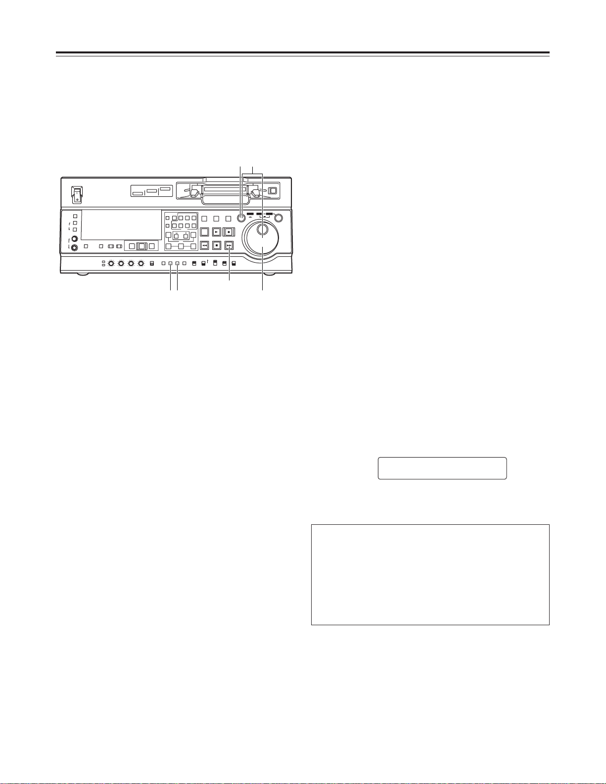
This VTR’s main settings are performed while making
selections using a system of menus.
If a TV monitor has been connected to the VIDEO
OUT 3 connector or SDI OUT 3 connector on the rear
panel, the setting menus are displayed on the TV
monitor.
Changing the settings
ON
OFF
POWER
DV
DVCPRO
DVCPRO 50
METER
L
R
FULL/FINE
MONITOR SELECT
HEADPHONES
MONITOR
MIX
A VOL
SELECT
INPUT SELECT
PREVIEW/PREVIEW
AUTO EDIT
PREROLL
VIDEO
REC LEVEL
CH1
PB LEVEL
AUDIO
CH2 CH3 CH4
TC
PRESET
MENU SET DIAG
SUPER REC INH
INT TCG
MODE
CONTROL
ON
OFF
UNITY
VAR
COUNTER
RESET
A IN
TRIM
SET
OUTIN
A OUT
CH1 CH4CH2
INSERT
CH3
ASSEM
VIDEO CUE TC
STAND BY
EDIT
REW STOP
PLAY REC
PLAYER
RECORDER
FF
JOG SHTL SLOW
TAPE
EE
ON
REGEN
PRESET
EXIT
OFF
REMOTE
LOCAL
4
261
3
FF button
Page 3
29
Setup menus
1
Press the MENU button.
2
When the FF button is pressed while holding down
the DIAG button, the next user file is selected;
conversely, when the REW button is pressed while
holding down the DIAG button, the previous user
file is selected.
3
To enter the selection made in step 2 for the user
file which is to be used, press the SET button.
The user file is changed and stored in the memory.
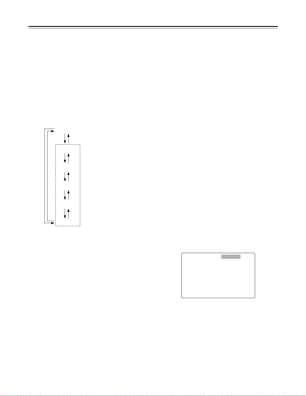
This VTR can hold five user files, each of which has
its own specific menu settings, and one of these files
can be selected for use.
Changing the file
1
Press the MENU button.
2
Press the REW button or FF button while holding
down the DIAG button to select the file for which
the lock mode is to be set or released.
3
Turn the search dial to move the cursor (2) on the
menu screen to No. 30 (MENU LOCK) for the
system file or to No. A03 (MENU LOCK) for a user
file.
4
Turn the search dial while holding down the search
button to select whether the lock mode is to be set
or released.
To set the lock mode:
Set 0001 (ON) as the setting.
To release the lock mode:
Set 0000 (OFF) as the setting.
When the lock mode has been set, “LOCKED”
flashes on the menu screen. The counter display
stops flashing and remains lighted.
5
Press the SET button.
The setting is stored in the memory.
The lock mode can be set to protect the system file
and user file (USER2 to USER5) settings. Once the
lock mode is set, no further changes can be made to
the settings.
Setting and releasing the lock mode can be set for the
system file by using setup menu No. 30 (MENU
LOCK) and for the user files by using setup menu No.
A03 (MENU LOCK).
Setting and releasing the lock mode
SYSTEM
FF REW
USER 1
FF REW
USER 2
FF REW
USER 3
FF REW
USER 4
FF REW
USER 5
FFREW
User files
Each user file contains the
following items.
O BASIC
O OPERATION
O INTERFACE
O EDIT
O TAPE PROTECT
O TIME CODE
O VIDEO
O AUDIO
O V BLANK
O MENU
<Note>
Since the SYSTEM menu items are not included in
user files 1 through 5, first select the user file and
switch to the SYSTEM file, and then set the SYSTEM
menu items.
<Notes>
O The lock mode cannot be set for the USER1 file.
O Once set to the lock mode, a file cannot be reset to
the factory settings even by pressing the RESET
button.
SETUP-MENU LOCKED
<USER2> NO.000-0005
2
000 P-ROLL TIME 5s
001 LOCAL ENA ST&EJ
002 TAPE TIMER ±12h
003 REMAIN SEL OFF
004 SETUP NUMBER OFF
005 METER SELECT CUE
006 SYNCHRONIZE ON
007 SUPER ON
008 DISPLAY SEL T&STA
Page 4
30
Setup menus
1
Press the MENU button.
2
Press the REW button or FF button while holding
down the DIAG button to select the USER1 file.
4
Turn the search dial while holding down the search
button to select the user file whose contents are to
be loaded into USER1.
6
Press the PLAY button.
The settings of the user file selected in step 4 are
loaded, and the USER1 menu display appears. If
the STOP button is pressed instead, the settings
are not changed, and the USER1 menu display
appears.
7
Turn the search dial to move the cursor (2) on the
menu screen to a number other than No. A00
(LOAD) or No. A01 (SAVE).
8
Press the SET button. The USER1 settings are
stored in the memory.
If the USER1 settings are not to be stored in the
memory, do not press the SET button but press the
MENU button instead.
5
Press the SET button.
The following message appears on the menu
screen and counter display.
3
Turn the search dial to move the cursor (2) on the
menu screen to No. A00 (LOAD).
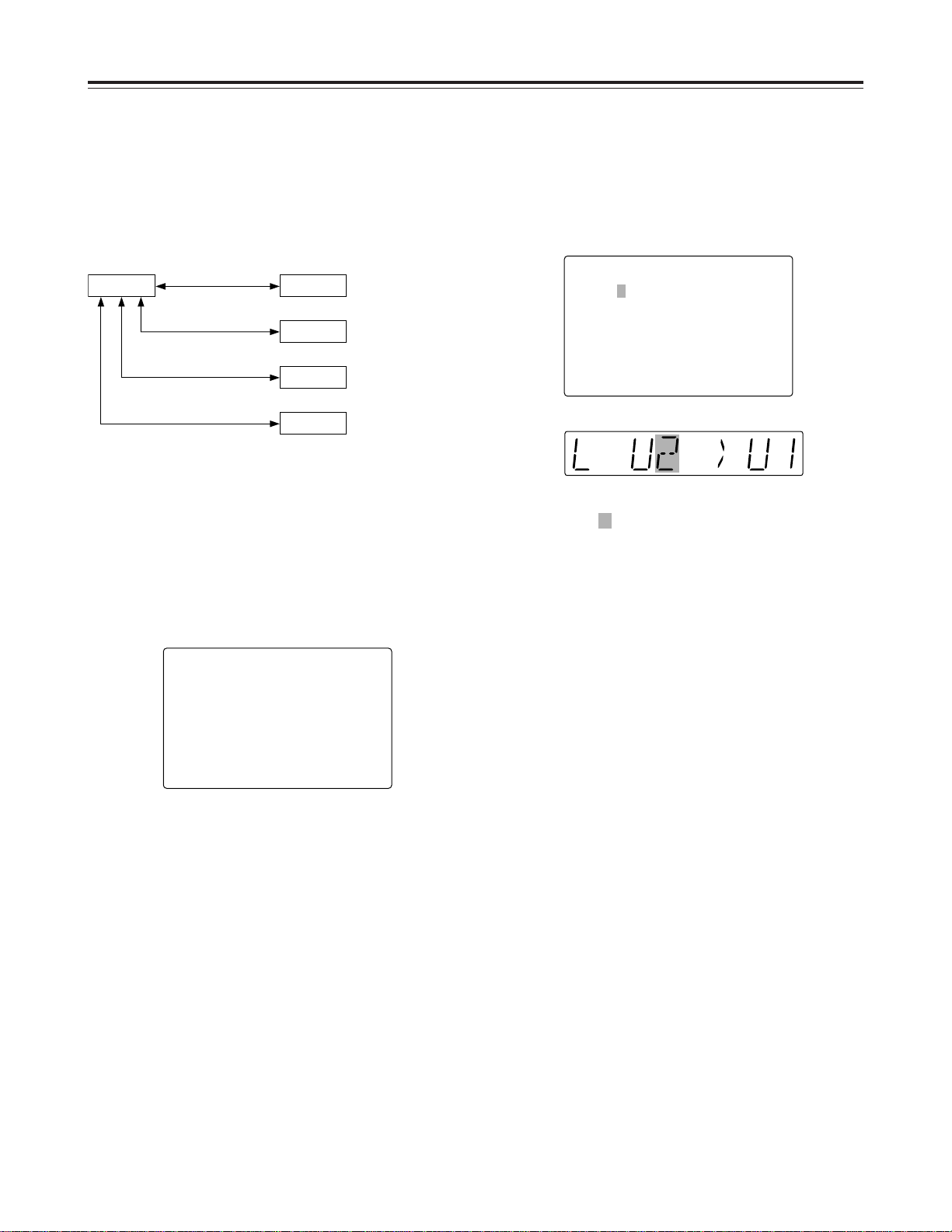
The contents of the USER2, USER3, USER4 or
USER5 file can be copied (loaded) into the USER1
file. Also, the contents of the USER1 file can be
copied (saved) into the USER2, USER3, USER4 or
USER5 file.
Loading user files
SETUP-MENU MENU
<USER1> NO.A00-0000
804 BLANK LINE BLANK
2
A00 LOAD USER2
A01 SAVE USER2
A02 P.ON LOAD OFF
END
SETUP-MENU LOAD
USER2 nUSER1 OK?
YES<PLAY>/NO<STOP>
USER 1 USER 2
USER 3
USER 4
USER 5
Load/save
Lock mode can be
set
Load/save
Lock mode can be
set
Load/save
Lock mode can be
set
Load/save
Lock mode can be
set
Menu screen
Counter display
The number of the user file selected in step 4 is
displayed at .
Page 5
31
Setup menus
1
Press the MENU button.
2
Press the REW button or FF button while holding
down the DIAG button to select the USER1 file.
4
Turn the search dial while holding down the search
button to select the user file in which the contents
of USER1 are to be saved.Those user files which
have been set to the lock mode do not appear on
the display. If all the user files have been set to the
lock mode, the “LOCKED” display appears, and
the contents of USER1 cannot be saved into any of
the user files.
3
Turn the search dial to move the cursor (2) on the
menu screen to No. A01 (SAVE).
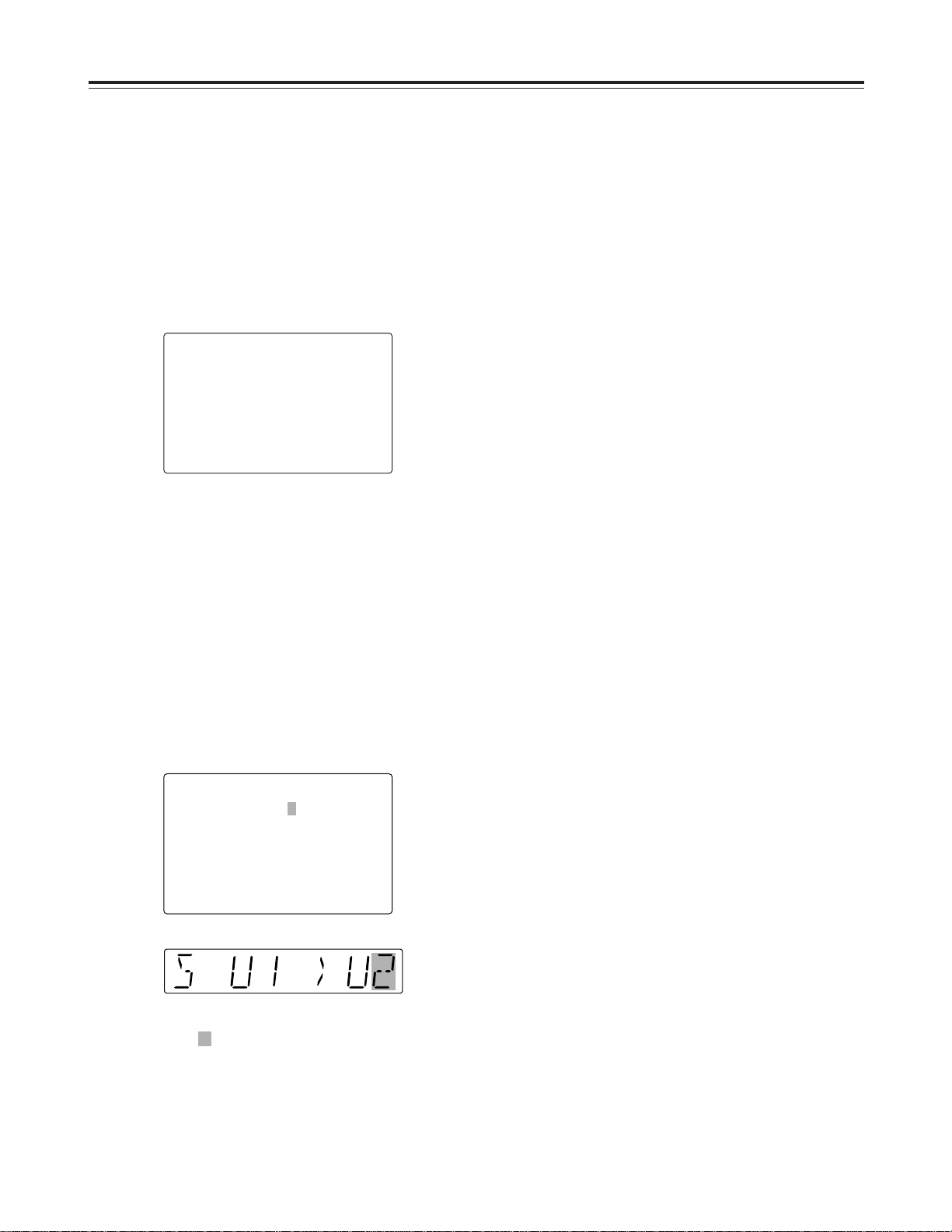
Saving user files
Automatically recalling a user file
when turning on the power
If the user file to be loaded is selected in advance
using setup menu No. A02 (P.ON LOAD), the file will
be automatically loaded into USER1 when the power
is turned on.
SETUP-MENU MENU
<USER1> NO.A00-0000
804 BLANK LINE BLANK
A00 LOAD USER2
2
A01 SAVE USER2
A02 P.ON LOAD OFF
END
5
Press the SET button.
The following message appears on the menu
screen and counter display.
SETUP-MENU SAVE
USER1 nUSER2 OK?
YES<PLAY>/NO<STOP>
Menu screen
Counter display
The number of the user file selected in step 4 is
displayed at .
6
Press the PLAY button.
The settings of USER1 are saved in the user file
selected in step 4 and stored in the memory. If the
STOP button is pressed instead, the settings are
not changed, and the USER1 menu display
appears.
7
Turn the search dial to move the cursor (2) on the
menu screen to a number other than No. A00
(LOAD) or No. A01 (SAVE).
8
Press the SET button. The USER1 settings are
stored in the memory.
If the USER1 settings are not to be stored in the
memory, do not press the SET button but press the
MENU button instead.
Page 6
32
Setup menus
SYSTEM menu
No./Item Description
The underlined items indicates the initial setting.
00
WFM SEL
This selects the signal to output from the
VIDEO OUT 2 connector.
0000 CTL
: The CTL signal is output.
0001 TC
: The TIME CODE signal is
output.
0002 VIDEO
: The VIDEO OUT signal is
output.
0003 RF_L
: The PB L RF signal is output.
0004 RF_R
: The PB R RF signal is output.
0005 ENV_L
: The PB L ENV signal is output.
0006 ENV_R
: The PB R ENV signal is output.
<Notes>
OThe settings can be changed at any time
regardless of the setup menu item No. 30
(MENU LOCK) setting.
ODuring normal playback, the output signals
have levels which are virtually identical to the
values given below under a 75Ω termination.
CTL: 0.1 to 0.3 Vp-p TC: 0.6 Vp-p
VIDEO: 1.0 Vp-p
10
ENCODER
SEL
This selects whether the video output signal
is to be adjusted with the VTR or with the
external encoder remote control.
0000 REMOTE
:
Video output signals are adjusted with the
external encoder remote control.
0001
LOCAL
:
Video output signals are adjusted with the
VTR.
11
SYS SC
COAR.
Coarse adjustment of system phase: 90° units
0000
0
0001 90
0002 180
0003 270
12
SYS SC FINE
Fine adjustment of system phase:
Variable range ±45° or more
–: Advanced, +: Delayed
0000 –128
::
0128 0
::
0255 127
13
SYS H
System phase adjustment: 74 ns steps
–: Advanced, +: Delayed
0000 –128
::
0108 0
::
0216 127
No./Item Description
14
SCH COARSE
SCH phase adjustment: 90° units
(The SC phase changes but the H phase does
not change.)
–: Advanced, +: Delayed
0000 0
0001 90
0002 180
0003 270
15
SCH FINE
SCH phase adjustment:
Total variable range: ±45° or more
(The SC phase changes but the H phase does
not change.)
–: Advanced, +: Delayed
0000 –32
::
0032 0
::
0064 32
16
AV PHASE
This adjusts the audio output phase with
respect to the video output: 20.8 µs steps
–: The audio output phase is advanced with
respect to the video output.
+: The audio output phase is delayed with respect
to the video output.
0000 –128
::
0128 0
::
0255 127
<Note>
If setting operation is
performed, the setting value
does not return to factory
(default) setting.
<Note>
If setting operation is
performed, the setting value
does not return to factory
(default) setting.
<Note>
If setting operation is
performed, the setting value
does not return to factory
(default) setting.
Page 7
33
Setup menus
The underlined items indicates the initial setting.
SYSTEM menu
No./Item Description
18
SYS H
OFFSET
System phase adjustment.
0000 –3
: –13.4 µsec
0001 –2
: –8.96 µsec
0002 –1
: –4.52 µsec
0003 0
: 0 sec
0004 1
: +4.52 µsec
0005 2
: +8.96 µsec
0006 3
: +13.4 µsec
<Note>
Factory settings will remain unchanged even if an
attempt is
19
SYS SC/H
This sets whether the system phase is to be
adjusted by the unit or from the external
encoder remote controller.
0000
REMOTE
:
The system phase is adjusted from the
external encoder remote controller.
0001 LOCAL
:
The system phase is adjusted by the unit.
<Note>
This setting does not take effect when LOCAL
has been selected as the SYSTEM menu item
No. 10 (ENCODER SEL) setting.
22
VIDEO LEVEL
This sets the video level.
Max. variable range: ±3 dB
0000 –128
::
0128 0
::
0255 127
23
[525i system]
SET UP LEVEL
[625i system]
BLACK LEVEL
SD955B
This sets the setup (black) level.
Max. variable range: 14 IRE (100 mV)
0000 –128
::
0128 0
::
0255 127
24
[525i system]
HUE
[625i system]
CHROMA PHASE
SD955B
This sets the hue (chroma phase).
Max. variable range: ±30°
0000 –128
::
0128
0
::
0255 127
25
CHROMA
LEVEL
This sets the chroma level.
Max. variable range: ±3 dB
0000 –128
::
0128
0
::
0255 127
No./Item Description
30
MENU LOCK
This selects whether the system file lock
mode is to be engaged or released.
0000 OFF
: The lock is released (file data
can be changed).
0001 ON
: The lock is engaged (file data
cannot be changed).
<Note>
Setup menu No. 00 (WFM SEL) can be changed
at any time regardless of the setting selected for
this menu item.
Video output signal adjustments
The video output signal adjustments are made by selecting the SYSTEM menu item No. 10 (ENCODER SEL) and
No. 19 (SYS SC/H) settings.
These adjustments can be used for analog component, analog composite and SDI signal output.
A control matrix of the adjustments is shown below.
Setting
SYSTEM menu item
10: ENCODER SEL
LOCAL
REMOTE
LOCAL
LOCAL
Unit
Unit
Unit
External encoder remote
controller
External encoder remote controller
REMOTE
REMOTE
SYSTEM menu item
19: SYS SC/H
SYSTEM menu item
11: SYS SC COAR.
12: SYS SC FINE
13: SYS H
SYSTEM menu item
22: VIDEO LEVEL
23: SET UP LEVEL/BLACK LEVEL
24: HUE/CHROMA PHASE
25: CHROMA LEVEL
Item adjusted
Page 8
34
Setup menus
The underlined items indicates the initial setting.
USER menu
<BASIC>
No./Item Description
000
P-ROLL TIME
This sets the preroll time.
The preroll time can be set from 0 to 15 seconds
in 1-second increments.
0000 0s
::
0005 5s
::
0015 15s
001
LOCAL ENA
This selects the buttons which can be operated
on the front panel when the CONTROL switch
has been set to REMOTE.
0000 DIS
:
No buttons can be operated.
0001 ST&EJ
:
Only the STOP and EJECT buttons can be
operated.
0002 ENA
:
AJ-SD955B: All buttons except for the
RECORDER and PLAYER
buttons can be operated.
AJ-SD930B: All buttons can be operated.
002
TAPE TIMER
This selects the 12 or 24 hour display for the
CTL counter.
0000 ±12h
: 12 hour display
0001 24h
: 24 hour display
006
SYNCHRONIZE
SD955B
This selects whether or not to synchronize
between two VTRs.
0000 OFF
:
No synchronization. The editing points deviate
several frames, but editing can be started
quickly.
0001 ON
:
Synchronization. Allows for error-free editing.
003
REMAIN SEL
This selects whether the remaining tape time
and total tape length are to be displayed in the
superimposed display of the VIDEO OUT 3/
SDI OUT 3 connector signals.
0000 OFF
: No display.
0001
2L
:
The remaining tape time is displayed on the
second line.
0002 1L
:
The remaining tape time is displayed on the
first line.
0003 R/TTL
:
The remaining tape time is displayed on the
first line, and the total tape length is displayed
in the second line.
<Notes>
OWhen “2L” is selected, the remaining tape time
is not displayed if “TIME” has been selected as
the setup menu item No.008 (DISPLAY SEL)
setting.
OWhen “R/TTL” is selected, the total tape length
is not displayed if “TIME” has been selected as
the setup menu item No.008 (DISPLAY SEL)
setting.
008
DISPLAY SEL
This selects what information is to be
provided by the time code and other super
displays output to the VIDEO OUT 3/SDI OUT 3
connector.
0000 TIME
: Data only.
(The data indicates the value for whichever of
CTL, TC or UB currently selected by the
COUNTER button.)
0001
T&STA
: Data and operation status.
0002 T&S&M
: Data, operation status and
mode.
0003 T&RT
: Data and REC TIME
0004 T&YMD
:
Data and REC DATE (year/month/day)
0005 T&MDY
:
Data and REC DATE (month/day/year)
0006 T&DMY
:
Data and REC DATE (day/month/year)
0007 T&UB
:
Data and user’s bit.
However, when UB has been selected with the
COUNTER button, the time code is displayed
after the user’s bit.
0008 T&CTL
:
Data and CTL data.
However, when CTL has been selected with
the COUNTER button, the time code is
displayed after the CTL data.
0009 T&T
:
Data and time code.
0010 VITC
:
The time code and user’s bit recorded in the
VAUX area are displayed.
<Notes>
OMode display:
DVCPRO 50 (50 Mbps) = DVCPRO_50,
DVCPRO (25 Mbps) = DVCPRO,
DV = DV, DVCAM = DVCAM
OAn error message appears if a warning or error
has occurred when “T&S&M” has been
selected as this setting.
OREC TIME and REC DATE are displayed
during DV/DVCAM, playback only. With the
DVCPRO50 (50 Mbps) or DVCPRO (25 Mbps)
format, the operating mode is displayed.
No./Item Description
<Note>
When the automatic editing
mode [PREVIEW, AUTO EDIT]
is set, the unit will not operate if
the preroll time is set to 0
seconds.
Page 9
35
Setup menus
The underlined items indicates the initial setting.
USER menu
<BASIC>
No./Item Description
015
MONI
CONTROL
SD955B
This sets whether the recorder is to be
forcibly set to the EE mode and the player’s
playback signals are to be output to the
monitor by pressing the recorder’s PLAYER
button when a monitor has been connected
only to the recorder during deck-to-deck
editing.
0000 MANU
:
The recorder is not forcibly set to the EE mode.
0001 AUTO
:
The recorder is forcibly set to the EE mode,
and the player’s playback signals are output.
017
CHARA SIZE
This selects the size of the characters for the
superimposed display output from the VIDEO
OUT 3 or SDI OUT 3 connector.
0000
NORMAL
: Standard size
0001 LARGE
: 4 times larger than the standard
size
<Note>
When LARGE has been selected, only time data
is displayed, regardless of the setup menu
No.008 (DISPLAY SEL) setting.
010
CHARA V-POS
This sets the position of the characters on the
vertical plane for the time code and other
super displays output to the VIDEO OUT 3/
SDI OUT 3 connector.
[525i system] [625i system]
0000 0 0000 0
::::
0018
18 0023 23
::::
0022 22 0028 28
<Notes>
OWhen setting this item, the DISPLAY SEL
status is output to VIDEO OUT 3/SDI OUT 3
even if SUPER OFF has been set. However,
when the menu is exited, operation complies
with the SUPER OFF/ON setting.
OWhen the DISPLAY SEL setting causes
characters to extend beyond the edges of the
screen, the setting value is changed so that the
characters are automatically displayed in a
position on the screen.
SD955B
011
CHARA TYPE
This selects the display type for the super
display output to the VIDEO OUT 3/SDI OUT 3
connector as well as for displays such as the
setting menu, etc.
0000
WHITE
: White characters against a black
background.
0001 W/OUT
: White characters with a black
border.
070
TV SYSTEM
SD955B
This selects the TV system.
0000
525
: The 525 interlace/59.94 Hz
system is selected.
0001 625
: The 625 interlace/50 Hz system
is selected.
<Note>
After this setting is changed, turn off and back on
the power again to take it effect.
012
SYS FORMAT
This sets the VTR’s recording and playback
format.
0000 50M
:
DVCPRO50 (50 Mbps) is selected.
0001 25M
:
DVCPRO (25 Mbps) is selected.
<Note>
The format complies with the setting of this menu
item when the tape is ejected.
013
PB FORMAT
This sets the format in which the tape is to be
played back.
0000
MANUAL
:
The format complies with the setting of setup
menu No. 012 (SYS FORMAT) when a
DVCPRO cassette is inserted.
The format complies to the format recorded on
the tape when a DV or DVCAM cassette is
inserted.
0001 AUTO
:
The format complies with the format recorded
on the tape.
<Notes>
OWhen an editing mode has been selected, the
“MANUAL” setting is forcibly established for
internal operations.
OWhen AUTO has been selected, the picture
and sound may be disturbed until the format is
detected after a tape is loaded.
No./Item Description
009
CHARA H-POS
This sets the position of the characters on the
horizontal plane for the time code and other
super displays output to the VIDEO OUT 3/
SDI OUT 3 connector.
0000 0
::
0004 4
::
0016 16
<Note>
When setting this item, the DISPLAY SEL status
is output to VIDEO OUT 3/SDI OUT 3 even if
SUPER OFF has been set. However, when the
menu is exited, operation complies with the
SUPER OFF/ON setting.
Also, CHARA TYPE is output to VIDEO OUT
3/SDI OUT 3 according to the status set in the
menu.
Page 10

36
Setup menus
The underlined items indicates the initial setting.
USER menu
<OPERATION>
No./Item Description
100
SEARCH ENA
This selects the direct search dial operation.
0000 DIAL
:
For direct search dial operations.
0001 KEY
:
Operation is not transferred to the search
mode unless the search button is pressed.
101
SHTL MAX
This sets the maximum speed for shuttle
operations.
0000 a8.4
: 8.4a normal speed
0001 a16
: 16a normal speed
0002 a32
: 32a normal speed
102
FF. REW MAX
This sets the maximum speed for FF and
REW operations.
0000 a16
: 16 (32)a normal speed
0001 a32
: 32 (60)a normal speed
0002 a50
: 50 (100)a normal speed
<Notes>
OThe speeds given in the parentheses apply in
the DVCPRO (25 Mbps), DV and DVCAM
mode.
OWith mini DV or mini DVCAM cassette, the
maximum speed is set to 32a regardless of
this item’s settings.
104
REF ALARM
This selects whether to warn the operator
when the REF. VIDEO signal has not been
connected.
0000 OFF
: Warning is not given.
0001
ON
: Warning is given by the flashing
STOP lamp.
<Note>
Video and audio output may be disturbed when
the reference video signal is not input, so it is
recommended that a system which inputs the
reference video signal be used.
105
AUTO EE SEL
This selects the VTR mode in which the EE
status is established when the MODE switch
is set to EE.
0000 S/F/R
: EE status is established in
STOP, FF, REW and EJECT modes.
0001 STOP
: EE status is established in STOP
and EJECT modes.
0002 BLACK
: EE status is established in STOP
and EJECT modes.
However, if the MODE switch is set to TAPE,
the picture becomes black and the sound is
muted when the tape is ejected.
0003 BLACK1
: EE status is established in
STOP, FF, REW and EJECT modes.
However, if the MODE switch is set to TAPE,
the picture becomes black and the sound is
muted when the tape is ejected.
0004 GRAY
: EE status is established in STOP
and EJECT modes.
However, if the MODE switch is set to TAPE,
the picture becomes gray and the sound is
muted when the tape is ejected.
0005 GRAY1
: EE status is established in
STOP, FF, REW and EJECT modes.
However, if the MODE switch is set to TAPE,
the picture becomes gray and the sound is
muted when the tape is ejected.
106
EE MODE SEL
This selects the EE mode output signals.
0000
NORMAL
:
Signals are output with a delay equivalent to
the length of internal signal processing.
0001 THRU
:
Signals are output directly, without internal
processing, and so are output with no delay.
<Note>
When the unit is in edit mode and SDTI/1394 or
SG has been selected for the input signals by the
INPUT SELECT button, internal operations are
forcibly set to NORMAL.
108
CAP. LOCK
This selects the CAPSTAN LOCK mode.
[525i system]
0000 2F
: 2F mode
0001 4F
: 4F mode
[625i system]
0000 2F
: 2F mode
0001 4F
: 4F mode
0002 8F
: 8F mode
SD955B
107
PLAY DELAY
This set the play delay time in frame
increments.
0000 0
::
0015 15
No./Item Description
Page 11

37
Setup menus
The underlined items indicates the initial setting.
USER menu
<OPERATION>
No./Item Description
111
FRZ MODE
SEL
This selects the output picture in the
STANDBY OFF (HALF LOADING) and EJECT
modes.
0000 DIS
:
The video output is muted.
0001 STB OFF
:
When the STANDBY OFF (HALF LOADING)
mode is established, the picture being played
back at the time is frozen and output.
0002 SOF&EJ
:
When the STANDBY OFF (HALF LOADING)
or EJECT mode is established, the picture
being played back at the time is frozen and
output.
<Notes>
OFreeze status complies with the setup menu
item No. 605 (FREEZE SEL) setting.
OIn the EJECT mode, freeze is output only when
BLACK, BLACK1, GRAY or GRAY1 is selected
as the setup menu item No. 105 (AUTO EE
SEL) setting.
112
V IN SEL INH
This selects whether video input switching
using the INPUT SELECT button is to be
enabled or disabled.
0000
OFF
:
Video input switching using the INPUT
SELECT button is enabled.
0001 ON
:
Video input switching using the INPUT
SELECT button is disabled.
0002 REC
:
Video input switching using the INPUT
SELECT button after the unit has been
transferred to a recording (but not editing)
mode is disabled.
113
A IN SEL INH
This selects whether audio input switching
using the INPUT SELECT button is to be
enabled or disabled.
0000 OFF
:
Audio input switching using the INPUT
SELECT button is enabled.
0001 ON
:
Audio input switching using the INPUT
SELECT button is disabled.
0002 REC
:
Audio input switching using the INPUT
SELECT button after the unit has been
transferred to a recording (but not editing)
mode is disabled.
<Note>
Even when the ON or REC setting is selected to
disable audio input switching using the INPUT
SELECT button, it is still possible to set the setup
menu items No. 715 (CH1 IN SEL), No. 716
(CH2 IN SEL), No. 717 (CH3 IN SEL), No. 718
(CH4 IN SEL), No. 719 (D IN SEL12) and No.
720 (D IN SEL34).
110
MEMORY
STOP
This selects whether the VTR is to stop
automatically when the counter value reaches
“0” during a fast forwarding or rewinding
operation in the CTL mode.
0000 OFF
: The VTR does not stop.
0001 ON
: The VTR stops automatically.
<Notes>
OThe stop mode concerned is either the stop or
the still-picture (SHTL STILL or SLOW STILL)
mode depending on the setup menu No. 315
(AFTER CUE-UP) setting.
OWhen both the AUTO REW function and
MEMORY function have been selected at the
same time, the AUTO REW function takes
precedence.
No./Item Description
Memory stop function
The MEMORY STOP function
does not work if it is activated
within a range of 0 ± 2 frames.
FF
button
Zero
point
FF
button
REW
button
REW
button
! When the FF button is pressed, the VTR performs the regular fast
forward operation since the zero point is not located in the
direction of operation.
@ When the REW button is pressed, the PREROLL lamp lights (the
SHTL lamp lights as well), the VTR proceeds with the preroll
operation, and it automatically stops when it reaches the position
where the counter reads “0.”
# When the REW button is pressed, the VTR performs the regular
rewinding operation since the zero point is not located in the
direction of operation.
$ When the FF button is pressed, the PREROLL lamp lights (the
SHTL lamp lights as well), the VTR proceeds with the preroll
operation, and it automatically stops when it reaches the position
where the counter reads “0.”
109
AUTO REW
This selects whether to rewind the tape
automatically to the tape start when the tape
end is detected.
0000 OFF
: The tape stops at the tape end.
0001 ON
: The tape is rewound to the tape
start.
3
4
1
2
Page 12

38
Setup menus
The underlined items indicates the initial setting.
USER menu
<OPERATION>
No./Item Description
114
REC INH
LAMP
This selects whether to cause the REC INH
lamp to flash or light up when the cassette
has been set to the accidental erasure
prevention status.
0000 LIGHT
: The lamp lights up.
0001 FLASH
: The lamp flashes.
<Note>
When the REC INH switch is set to ON, the REC
INH lamp always lights regardless of the general
setting status.
115
EJECT SW
INH
This selects whether to enable or disable the
operation of the EJECT button on the front
panel.
0000
REC
: Operation is disabled while the
unit is in the recording mode.
0001 OFF
: Operation is enabled in all
modes.
116
EJECT LAMP
This selects whether the EJECT lamp is to
remain lighted or be turned off in the cassette
out status.
0000 MODE1
:
The EJECT lamp remains lighted.
0001 MODE2
:
The EJECT lamp goes off.
117
DIAL LAMP
This selects the conditions under which the
dial ring on the front panel is to light.
0000 OFF :
The dial ring does not light.
0001 MODE1 :
The dial ring lights during search
(JOG/SLOW/SHTL) mode.
0002 MODE2 :
The dial ring lights during JOG
mode.
0003 MODE3 :
The dial ring lights when a
cassette is inserted.
Page 13

39
Setup menus
The underlined items indicates the initial setting.
USER menu
<INTERFACE>
No./Item Description
200
PARA RUN
This selects whether two or more VTRs are to
be operated in synchronization.
0000 DIS
: No operation in synchronization
0001 ENA
: Operation in synchronization
<Note>
When operating two or more VTRs in
synchronization, set all the VTRs to ENA.
202
ID SEL
This sets the ID information to be returned to
the controller.
0000 OTHER
0001 DVCPRO
0002 ORIG
<Notes>
OID information of any VTR except for the
DVCPRO’s is set in OTHER.
OThe ORIG setting should only be used when a
Panasonic controller (AG-A850 etc. sold
separately) is connected.
203
25P SEL
This selects whether the PARALLEL (25P)
connector functions when the CONTROL
switch has been set to REMOTE.
0000 OFF
: Connector does not function.
0001 ON
: Connector functions.
205
BAUD RATE
These settings are for selecting the RS-232C
communication speed (baud rate).
0000 300
0001 600
0002 1200
0003 2400
0004 4800
0005 9600
204
RS232C SEL
This selects whether the RS-232C connector
functions when the CONTROL switch has
been set to REMOTE.
0000 OFF
: Connector does not function.
0001 ON
: Connector functions.
206
DATA
LENGTH
These settings are for selecting the RS-232C
data length. (Unit: bit)
0000 7
0001 8
207
STOP BIT
These settings are for selecting the RS-232C
stop bit length. (Unit: bit)
0000 1
0001 2
201
9P SEL
This selects whether the REMOTE (9P)
connector functions when the CONTROL
switch has been set to REMOTE.
0000 OFF
: Connector does not function.
0001
ON
: Connector functions.
208
PARITY
These settings are for selecting the none, odd
or even for the RS-232C parity bit.
0000 NON
:
Parity bit is not used.
0001 ODD
:
An odd number of bits is used for the parity
system.
0002 EVEN
:
An even number of bits is used for the parity
system.
No./Item Description
209
RETURN ACK
These settings are for selecting whether the
ACK code is to be returned when a command
is received from RS-232C.
0000 OFF
: ACK code is not returned.
0001 ON
: ACK code is returned.
210
25P STBY
CMD
For selecting the method used to detect the
STANDBY COMMAND signal input at the
PARALLEL (25P) connector.
0000
OFF/ON
:
Each time active signals are detected, the
STANDBY ON or STANDBY OFF mode is
selected alternately.
0001 ON
:
When active signals are detected in the
STANDBY OFF mode, the unit is transferred to
the STANDBY ON mode.
Nothing happens if they are detected during an
operation in the STANDBY ON mode.
212
MASTER
PORT
SD955B
For selecting the remote control connector to
control the slave when the unit is used as the
master during deck-to-deck operations.
0000
IN/OUT
: The IN/OUT connector is used.
0001 OUT
: The OUT connector is used.
<Note>
This menu item takes effect only when the
CONTROL switch has been set to the LOCAL
position.
211
LOCAL 25P
This selects whether the PARALLEL (25P)
connector is to function when the CONTROL
switch is at the LOCAL position.
0000
OFF
: Connector does not function.
0001 ON
: Connector functions.
Page 14

40
Setup menus
The underlined items indicates the initial setting.
USER menu
<EDIT>
No./Item Description
301
IN/OUT DEL
SD955B
This selects the operation to be performed
when an edit point has been set incorrectly
(when the OUT point is before the IN point).
0000 MANU
:
Editing is not executed unless the illegal edit
point is cleared or set again properly.
0001 AUTO
:
The edit points already input are automatically
cleared.
303
STD/
NON-STD
This selects STD or NON-STD in accordance
with the composite input signal.
0000 AUTO
:
Standard/non-standard signals are
automatically identified and processed.
0001 STD
:
Standard signals are processed. (Forced STD)
0002 N-STD
:
Non-standard signals are processed. (Forced
NON-STD)
<Note>
Use the non-standard (N-STD) setting when
video or audio trouble occurs with signals from
laser discs or a satellite.
304
SERVO REF
This selects the video signal processing.
0000
AUTO
:
Servo is synchronized with the input signal
during recording and editing, or with the REF
signal during playback.
0001 EXT
:
Servo is synchronized at all times with the REF
signal.
305
EDIT RPLCE1
This sets the channel assignments for the
controller’s analog audio preset when editing
the digital audio of the VTR using a controller
which does not have a digital audio edit
preset control function.
This selects the channel concerned when the
VTR CH1 edit preset is set in compliance with
the ON or OFF presetting for the analog audio
signals designated by the controller.
0000 N-DEF
:
Not set.
0001 CH1
:
Compliance with analog CH1 edit preset.
0002 CH2
:
Compliance with analog CH2 edit preset.
0003 CH1+2
:
Compliance with either analog CH1 or CH2
edit preset.
306
EDIT RPLCE2
The same type of setting as setup menu No.
305. This selects the channel concerned when
the CH2 edit preset is set in compliance with
the ON or OFF presetting for the analog audio
signals designated by the controller.
0000 N-DEF
:
Not set.
0001 CH1
:
Compliance with analog CH1 edit preset.
0002 CH2
:
Compliance with analog CH2 edit preset.
0003 CH1+2
:
Compliance with either analog CH1 or CH2
edit preset.
No./Item Description
307
EDIT RPLCE3
The same type of setting as setup menu No.
305. This selects the channel concerned when
the CH3 edit preset is set in compliance with
the ON or OFF presetting for the analog audio
signals designated by the controller.
0000 N-DEF
:
Not set.
0001 CH1
:
Compliance with analog CH1 edit preset.
0002 CH2
:
Compliance with analog CH2 edit preset.
0003 CH1+2
:
Compliance with either analog CH1 or CH2
edit preset.
308
EDIT RPLCE4
The same type of setting as setup menu No.
305. This selects the channel concerned when
the CH4 edit preset is set in compliance with
the ON or OFF presetting for the analog audio
signals designated by the controller.
0000
N-DEF
:
Not set.
0001 CH1
:
Compliance with analog CH1 edit preset.
0002 CH2
:
Compliance with analog CH2 edit preset.
0003 CH1+2
:
Compliance with analog CH1 or CH2 edit
preset.
Page 15

41
Setup menus
The underlined items indicates the initial setting.
USER menu
<EDIT>
No./Item Description
320
VAR FWD
MAX
This sets the maximum SLOW FWD speed.
0000 +4.1
: +4.1 (+3.1)a speed
0001 +1.85
: +1.85a speed
0002 +1
: +1a speed
<Notes>
OThe value for the DV/DVCAM tape is shown in
parenthesis ( ).
OAt any speed setting other than +4.1, the
phase cannot be synchronized from the editing
controller.
323
JOG FWD
MAX
This sets the maximum JOG FWD speed.
0000 +4.1
: +4.1 (+3.1)a speed
0001 +1.85
: +1.85a speed
0002 +1
: +1a speed
<Notes>
OThe value for the DV/DVCAM tape is shown in
parenthesis ( ).
OThe maximum speed is set to +1a when the
dial on the front panel is operated.
OAt any speed setting other than +4.1, the
phase cannot be synchronized from an editing
controller which synchronizes the phase using
the JOG command.
324
JOG REV MAX
This sets the maximum JOG REV speed.
0000 –4.1
: –4.1 (–3.1)a speed
0001 –1.85
: –1.85a speed
0002 –1
: –1a speed
0003 –0.43
: –0.43 (–0.5)a speed
<Notes>
OThe value for the DV/DVCAM tape is shown in
parenthesis ( ).
OThe maximum speed is set to –1a when the
dial on the front panel is operated.
325
POSTROLL
TM
SD955B
This sets the postroll time.
Any time from 0 to 5 seconds can be set in 1second units.
0000 0s
0001 1s
0002 2s
0003 3s
0004 4s
0005 5s
321
VAR REV MAX
This sets the maximum SLOW REV speed.
0000 –4.1
: –4.1 (–3.1)a speed
0001 –1.85
: –1.85a speed
0002 –1
: –1a speed
0003 –0.43
: –0.43a speed
<Note>
The value for the DV/DVCAM tape is shown in
parenthesis ( ).
No./Item Description
309
EDIT RPLCEC
The same type of setting as setup menu No.
305. This selects the channel concerned when
the CUE edit preset is set in compliance with
the ON or OFF presetting for the analog audio
signals designated by the controller.
0000 N-DEF
:
Not set.
0001 CH1
:
Compliance with analog CH1 edit preset.
0002 CH2
:
Compliance with analog CH2 edit preset.
0003 CH1+2
:
Compliance with either analog CH1 or CH2
edit preset.
310
CONFI EDIT
This selects whether to conduct simultaneous
playback while editing is in progress.
0000 OFF
: No simultaneous playback
0001 ON
: Simultaneous playback
<Note>
Simultaneous playback is valid when the MODE
switch is set to TAPE.
311
AUD EDIT IN
This selects the connection method for the
digital audio edit IN point.
0000 CUT
: Cut processing
0001
FADE
: V Fade processing
312
AUD EDIT
OUT
This selects the connection method for the
digital audio edit OUT point.
0000 CUT
: Cut processing
0001 FADE
: V Fade processing
313
AUTO ENTRY
SD955B
This selects whether the IN point is to be
entered using the PREROLL button when it
has not been entered.
0000 DIS
: IN point is not entered.
0001 ENA
: IN point is entered.
314
CF ADJ SEL
SD955B
This selects the CF adjustment deck with
deck-to-deck editing.
0000
PLAYER
:
The player’s edit IN/OUT points are adjusted.
(reference as the RECORDER side)
0001 RECORD
:
The recorder’s edit IN/OUT points are
adjusted. (reference as the PLAYER side)
315
AFTER
CUE-UP
This selects the mode after cue-up operation
is complete.
0000
STOP
: STOP mode
0001 STILL
: SHTL STILL mode
0002 STILL2
: SLOW STILL mode
Page 16

42
Setup menus
The underlined items indicates the initial setting.
USER menu
<TAPE PROTECT>
No./Item Description
400
STILL TIMER
This selects the time to be taken until the unit
goes into the tape protection mode when it is
left standing in the stop or search still
(JOG/SLOW/SHTL) mode.
(Unit: s = second, min = minute)
0000 0.5s
0001 5s
0002 10s
0003 20s
0004 30s
0005 40s
0006 50s
0007 1min
0008
2min
401
SRC
PROTECT
When the time selected as the setup menu
item No. 400 (STILL TIMER) setting elapses
while the unit is in the search STILL
(JOG/SLOW/SHTL) mode, the unit
automatically enters one of the tape
protection modes. This menu item is for
selecting which tape protection mode the unit
is to enter.
0000 STEP
: STEP FWD
0001 HALF
: HALF LOADING
<Note>
When STEP FWD is selected, the unit
automatically goes into the STANDBY OFF
(HALF LOADING) mode when the total time for
which the unit is left standing in the still status
reaches 30 minutes (or 1 minute for a
DV/DVCAM tape).
402
DRUM STDBY
This selects the drum operation in the
STANDBY OFF (HALF LOADING) mode.
0000 OFF
: The drum stops rotating.
0001 ON
: The drum continues rotating.
<Notes>
OSTEP FWD and HALF
LOADING are provided in the
tape protection mode. Either
of these can be set for STOP
and SEARCH STILL.
OThe cumulative standby time
at the same tape position
increases when transmitting
programs or otherwise using
identical materials
repeatedly.
In order to protect the tape, it
is recommended that the
shortest possible setting for
the standby time in the same
tape location is used.
OWhen a DV/DVCAM tape is
used, any setting above 10
seconds will be treated as 10
seconds.
No./Item Description
403
STOP
PROTECT
When the time selected as the setup menu
item No. 400 (STILL TIMER) setting elapses
while the unit is in the STOP mode, the unit
automatically enters one of the tape
protection modes. This menu item is for
selecting which tape protection mode the unit
is to enter.
0000 STEP
: STEP FWD
0001 HALF
: HALF LOADING
<Note>
When STEP FWD is selected, the unit is
automatically transferred to the STANDBY OFF
(HALF LOADING) mode when the total time
during which it has been left standing in the
STOP mode reaches 30 minutes (or 1 minute for
a DV/DVCAM tape).
Page 17

43
Setup menus
The underlined items indicates the initial setting.
USER menu
<TIME CODE>
No./Item Description
506
BINARY GP
This sets the usage status of the user bit of
the time code generated by the TCG.
0000 000
:
NOT SPECIFIED (character set not specified)
0001 001
:
ISO CHARACTER (8 bits character set based
on ISO646, ISO2022)
0002 010
: UNASSIGNED 1 (undefined)
0003 011
: UNASSIGNED 2 (undefined)
0004 100
: UNASSIGNED 3 (undefined)
0005 101
: PAGE/LINE
0006 110
: UNASSIGNED 4 (undefined)
0007 111
: UNASSIGNED 5 (undefined)
507
PHASE CORR
This selects whether to control the phase
correction of the LTC which is output from
the TIME CODE OUT connector.
0000
OFF
:
Phase correction control is not performed.
0001 ON
:
Phase correction control is performed.
508
TCG CF FLAG
This selects whether the CF flag of the TCG is
to ON.
0000 OFF
: CF flag is OFF.
0001 ON
: CF flag is ON.
509
DF MODE
This selects the DF or NDF mode for CTL and
TCG.
0000 DF
: The drop frame mode is used.
0001 NDF
: The non-drop frame mode is
used.
<Notes>
ODrop frame mode is valid only when the
CONTROL switch is set to LOCAL or the setup
menu No. 001 (LOCAL ENA) is set to ENA.
OThis setup menu is not displayed in the 625i
system.
510
TC OUT REF
This is used to switch the phase of the time
code, which is output from the TIME CODE
OUT connector, for the external LTC input
when the TCG switch is at the EXT position.
0000 V OUT
:
Time code is synchronized with output video
signal.
0001 TC_IN
:
Time code is synchronized with external time
code input.
No./Item Description
500
VITC BLANK
For selecting whether to output the VITC
signal at the positions selected by setup
menu items No. 501 (VITC POS-1) and No. 502
(VITC POS-2).
0000 BLANK
: VITC signals are not output.
0001 THRU
: VITC signals are output.
501
VITC POS-1
This sets the position where the VITC signal
is to be inserted.
[525i system] [625i system]
0000 10L 0000 7L
::::
0006
16L 0004 11L
::::
0010 20L 0015 22L
<Note>
The same line as the one used for the setup
menu items No. 502 (VITC POS-2) and No. 662
(UMID POS) setting cannot be set.
SD955B
503
TCG REGEN
This selects the signal to be regenerated
when the time code generator (TCG) in the
REGEN mode.
0000 TC&UB
:
Both the time code and user bit are
regenerated.
0001 TC
:
Only the time code is regenerated.
0002 UB
:
Only the user bit is regenerated.
504
REGEN MODE
This selects whether the time code is to be
regenerated during automatic editing using
the unit’s control panel.
0000 AS&IN
:
Time code is regenerated with assemble or
insert editing.
0001 ASSEM
:
Time code is regenerated with assemble
editing.
0002 INSRT
:
Time code is regenerated with insert editing.
0003 SW
:
Setting complies with TCG switch setting.
505
EXT TC SEL
This selects the time code to be used when
an external time code is to be used.
0000 LTC
:
The LTC of the TIME CODE IN connector is
used.
0001 VITC
:
The VITC of the input video signal is used.
502
VITC POS-2
This sets the position where the VITC signal
is to be inserted.
[525i system] [625i system]
0000 10L 0000 7L
::::
0008 18L 0006 13L
::::
0010 20L 0015 22L
<Note>
The same line as the one used for the setup
menu items No. 501 (VITC POS-1) and No. 662
(UMID POS) setting cannot be set.
SD955B
Page 18

44
511
VITC OUT
This selects how the VITC which is to be
superimposed onto the output video signal is
to be output.
0000 SBC
:
During recording:
The input time code, which was selected by
the setup menu No. 505 (EXT TC SEL)
setting and TCG switch, is output as the
VITC.
During playback:
The time code recorded in the SBC area is
output as the VITC.
0001 VAUX
:
During recording:
The time code detected from the input video
signal is output as the VITC.
During playback:
The time code recorded in the VAUX area is
output as the VITC.
<Note>
The time code detected from the input video
signal is automatically recorded in the VAUX area
while pictures are being recorded.
Setup menus
The underlined items indicates the initial setting.
USER menu
<TIME CODE>
No./Item Description
514
VITC GEN
This selects whether or not to record the
internal time code generator value in the
VAUX area.
0000 OFF
:
The internal time code generator value is not
recorded in the VAUX area.
When video signals on which the time code
has been recorded are input, the time code of
the input signals is recorded in the VAUX area.
0001 ON
:
The internal time code generator value is
recorded in the VAUX area.
<Note>
If SDTI/1394 has been selected as the input
signals using the INPUT SELECT button, the
time code on the input signals will be recorded
regardless of this menu’s setting.
No./Item Description
512
TC OUT ADV
This selects how the phase alignment for the
time code output from the TIME CODE OUT
connector is to be handled.
Usually, it is aligned with the output video and
audio signals.
However, when external components are to be
connected, it is possible to align the phase with
the input signal.
0000 OFF
:
Phase alignment is not performed.
The time code output from the TIME CODE
OUT connector is aligned with the output video
and audio signals.
0001 EDIT
:
When editing mode has been selected, the
time code output from the TIME CODE OUT
connector is aligned with the input video and
audio signals during playback and editing
operations.
In all other modes it is aligned with the output
video and audio signals.
513
RUN MODE
This sets the operation mode which is to
make the internal time code generator
advance.
0000 REC
:
The internal time code generator is advanced
during recording.
0001 FREE
:
When the power is on, the internal time code
generator is advanced regardless of the
operation mode.
SBC (sub code data) area:
This area is separate from the video and audio data area on the
helical track. The time code complying with SMPTE/EBU standards
is stored here. As with the conventional LTC (linear time code), the
time code can be read even during rewinding or fast forwarding. It
can also be read out when the tape has stopped.
VAUX (video auxiliary data) area:
This area is to be found in the video data area on the helical track.
The additional information relating to the video data is stored here.
<Note>
The time code and user’s bit are controlled during tape playback by
the data which has been recorded in the SBC area. This means that
all the data recorded in the SBC area alone is used as the data
which is to be indicated on the counter display section in the middle
of the front panel or in the superimposed display, or as the data
which is to be transmitted to the editing controller or other unit.
Page 19

45
Setup menus
The underlined items indicates the initial setting.
USER menu
<VIDEO>
No./Item Description No./Item Description
600
INT SG
This selects the internal reference signal.
0001 BB
:
The black burst is generated.
0002 CB100
:
100% color bars are generated.
0003 CB75
:
75% color bars are generated.
601
OUT VSYNC
This selects whether to float the vertical sync
position of the video output in order to align
the video output phase with the input in the
EE/record/edit modes.
0000 N-VF
: Signals are not floated.
0001 VF
: Signals are floated.
602
V-MUTE SEL
This selects whether to mute the video output
signals when a blank on the tape has been
detected during playback.
0000 N-MUTE
: No muting. (Freeze)
0001
LOW RF
: Muting. (Set to gray.)
603
CC (F1)
BLANK
This selects ON or OFF for the closed caption
signal of the first field.
0000 BLANK
: Signal is forcibly blanked.
0001 THRU
: Signal is not blanked.
<Note>
This setup menu is not displayed in the 625i
system.
604
CC (F2)
BLANK
This selects ON or OFF for the closed caption
signal of the second field.
0000 BLANK
: Signal is forcibly blanked.
0001 THRU
: Signal is not blanked.
<Note>
This setup menu is not displayed in the 625i
system.
606
OUT C KILL
This selects chroma color killer processing
for the video output signals.
0000 B/W
: No color signals are output.
0001
COLOR
: Color signals are output.
609
EDH
This selects whether to superimpose EDH
onto the SDI output signals.
0000 OFF
: EDH is not superimposed.
0001 ON
: EDH is superimposed.
<Note>
Even when ON is selected for this setting, EDH is
not superimposed onto the signals output from
the SDI OUT 3 connector if the SUPER switch on
the front panel of the unit is set to ON.
610
P
B/PR IN LV
This selects the analog component input
level.
0000 M
II : M II level
0001
B-CAM
: ß-CAM level
<Notes>
OThis setup menu is not displayed in the 625i
system.
OWhen no optional board (AJ-YA931G) has
been installed, setup menu No. 610 is not
displayed.
614
PB/PR OUT LV
This selects the analog component output
level.
0000 M
II : M II level
0001
B-CAM
: ß-CAM level
<Note>
This setup menu is not displayed in the 625i
system.
611
YC SEP MODE
This selects Y/C separation processing for
the composite input signals.
0000 B/W
:
The signals are processed as B/W signals.
0001 AUTO
:
The signals are automatically detected.
<Note>
When no optional board (AJ-YA931G) has been
installed, setup menu No. 611 is not displayed.
618
INTERPOLATE
This selects the interpolation operation.
Vertical interpolation is conducted automatically
during slow-motion playback to reduce the
vertical movement of the playback pictures.
However, this menu item enables the
interpolation operation to be forcibly turned off.
0000 OFF
:
Interpolation is forcibly turned off.
0001 AUTO
:
Interpolation is automatically turned on during
slow-motion playback.
605
FREEZE SEL
This selects the freeze mode for still pictures.
0000 FIELD
: Field freeze.
0001 FRAME
: Frame freeze.
<Note>
When frame freeze has been selected, the frame
slow status is established with the slow setting.
Page 20

46
Setup menus
The underlined items indicates the initial setting.
USER menu
<VIDEO>
No./Item Description No./Item Description
621
CCR MODE
This selects the cross color processing
during playback.
0000 OFF
:
The cross color is output with no changes
made.
0001 ON
:
The cross color can be reduced.
<Note>
This setup menu is not displayed in the 625i
system.
622
SETUP 25
For setting 7.5% setup processing to be
performed on input and output signals in the
DVCPRO (25 Mbps) mode.
When the STOP button is pressed, operation is
transferred to the sub-screen, and the setup level
is set for each output. To return from the subscreen, press the STOP button again.
<Note>
This setup menu is not displayed in the 625i
system.
00
CMPST IN
Sub-screen
This selects the 7.5% setup processing for
the input composite signal.
0000 THRU
:
The signal is recorded in its original form.
0001 CUT
:
The signal is recorded with the 7.5% setup
removed.
02
CMPNT IN
This selects the 7.5% setup processing for
the input component signal.
0000
THRU
:
The signal is recorded in its original form.
0001 CUT
:
The signal is recorded with the 7.5% setup
removed.
03
CMPNT OUT
This selects the 7.5% setup processing for
the output composite, component and serial
(digital) signal.
0000 THRU
:
The signal is output in its original form.
0001 CUT
:
The signal is output with the 7.5% setup
removed.
0002 ADD
:
The signal is output with the 7.5% setup
added.
01
CMPST OUT
This selects the 7.5% setup processing for
the output composite signal.
0000 THRU
:
The signal is output in its original form.
0001 ADD
:
The signal is output with the 7.5% setup
added.
<Note>
Bear in mind the setting for sub-screen item No.
03 (CMPNT OUT) of setup menu item No. 622
(SETUP 25).
620
ESR MODE
This selects the operation mode for edge
subcarrier reduction (ESR) in the playback
circuit.
0000 OFF
:
The mode is forcibly set to OFF.
0001 AUTO
:
The mode is automatically set to ON or OFF
depending on the VTR operation.
Page 21

47
Setup menus
The underlined items indicates the initial setting.
USER menu
<VIDEO>
No./Item Description
623
SETUP 50
For setting 7.5% setup processing to be
performed on input and output signals in the
DVCPRO50 (50 Mbps) mode.
When the STOP button is pressed, operation is
transferred to the sub-screen, and the setup level
is set for each output. To return from the subscreen, press the STOP button again.
<Note>
This setup menu is not displayed in the 625i
system.
00
CMPST IN
Sub-screen
This selects the 7.5% setup processing for
the input composite signal.
0000 THRU
:
The signal is recorded in its original form.
0001 CUT
:
The signal is recorded with the 7.5% setup
removed.
02
CMPNT IN
This selects the 7.5% setup processing for
the input component signal.
0000
THRU
:
The signal is recorded in its original form.
0001 CUT
:
The signal is recorded with the 7.5% setup
removed.
03
CMPNT OUT
This selects the 7.5% setup processing for
the output composite, component and serial
(digital) signal.
0000 THRU
:
The signal is output in its original form.
0001 CUT
:
The signal is output with the 7.5% setup
removed.
0002 ADD
:
The signal is output with the 7.5% setup
added.
01
CMPST OUT
This selects the 7.5% setup processing for
the output composite signal.
0000 THRU
:
The signal is output in its original form.
0001 ADD
:
The signal is output with the 7.5% setup
added.
<Note>
Bear in mind the setting for sub-screen item No.
03 (CMPNT OUT) of setup menu item No. 623
(SETUP 50).
No./Item Description
624
CC REC
For selecting whether to record the closed
caption signals multiplexed on the input
signals on the tape.
0000 OFF
:
No closed caption signal is recorded.
In addition, the EE output signals are blanked.
0001 ON
:
When a closed caption signal is detected from
the selected input signal, it can be recorded.
<Notes>
OIf SDTI/1394 signals have been selected as
the input signals, the closed caption signals
which have been multiplexed onto the input
signals will be recorded on the tape regardless
of the setting.
OThis setup menu is not displayed in the 625i
system.
660
UMID REC
This selects whether or not to record the
UMID information on the tape.
0000 OFF
:
UMID information is not recorded on the tape.
In addition, EE output signals are blanked.
0001 ON
:
UMID information is recorded on the tape.
<Notes>
OIf SDTI/1394 has been selected as the input
signals using the INPUT SELECT button, the
UMID information on the input signals will be
recorded regardless of this menu’s setting.
OIf THRU has been selected as the setup menu
item No. 106 (EE MODE SEL) setting, UMID
information of the EE output signals will be
blanked.
645
WIDE SELECT
This selects whether or not to record the
wide-screen information on the tape.
0001 WIDE
:
The wide-screen information is not recorded on
the tape.
0002
NORMAL
:
The wide-screen information is recorded on the
tape.
<Note>
If SDTI/1394 has been selected as the input
signals using the INPUT SELECT button, the
wide-screen information on the input signals will
be recorded regardless of this menu’s setting.
Page 22

48
Setup menus
The underlined items indicates the initial setting.
USER menu
<VIDEO>
No./Item Description
661
UMID GEN
This selects the basic UMID information to be
recorded on the tape when ON has been
selected as the setup menu item No. 660
(UMID REC) setting.
0000 INT
:
Newly created basic UMID information of this
unit is always recorded.
0001 EXT
:
The basic UMID information of the input
signals is recorded.
Newly created basic UMID information of this
unit is recorded if there is no basic UMID
information on the input signals.
<Note>
The source pack (of the UMID information) of the
input signal will be recorded on the tape,
regardless of this menu’s setting.
662
UMID POS
This sets the line on which the UMID
information is to be superimposed.
[525i system] [625i system]
0000 BLANK 0000 BLANK
0001 12L 0001 8L
::::
0006
17L 0010 17L
::::
0008 19L 0015 22L
<Note>
The line selected for the setup menu item No.
501 (VITC POS-1) and No. 502 (VITC POS-2)
settings cannot be selected for this item.
SD955B
Page 23

49
Setup menus
The underlined items indicates the initial setting.
USER menu
<AUDIO>
No./Item Description No./Item Description
701
CH1 IN LV
This selects the audio input (CH1) reference
level switching.
0000 4dB
0001 0dB
0002 –20dB
702
CH2 IN LV
This selects the audio input (CH2) reference
level switching.
0000 4dB
0001 0dB
0002 –20dB
703
CH3 IN LV
This selects the audio input (CH3) reference
level switching.
0000 4dB
0001
0dB
0002 –20dB
704
CH4 IN LV
This selects the audio input (CH4) reference
level switching.
0000 4dB
0001 0dB
0002 –20dB
706
CH1 OUT LV
This selects the audio output (CH1) reference
level switching.
0000 4dB
0001 0dB
0002 –20dB
707
CH2 OUT LV
This selects the audio output (CH2) reference
level switching.
0000 4dB
0001 0dB
0002 –20dB
708
CH3 OUT LV
This selects the audio output (CH3) reference
level switching.
0000 4dB
0001 0dB
0002 –20dB
709
CH4 OUT LV
This selects the audio output (CH4) reference
level switching.
0000 4dB
0001
0dB
0002 –20dB
711
MONIL OUT
LV
This selects the audio monitor output (Lch)
reference level switching.
0000 4dB
0001 0dB
0002 –20dB
712
MONIR OUT
LV
This selects the audio monitor output (Rch)
reference level switching.
0000 4dB
0001 0dB
0002 –20dB
715
CH1 IN SEL
This selects the CH1 input when USER SET
has been selected by pressing the unit’s
AUDIO input selector button.
0000 ANA
: Analog input.
0001 DIGI
: Digital input.
716
CH2 IN SEL
This selects the CH2 input when USER SET
has been selected by pressing the unit’s
AUDIO input selector button.
0000 ANA
: Analog input.
0001 DIGI
: Digital input.
717
CH3 IN SEL
This selects the CH3 input when USER SET
has been selected by pressing the unit’s
AUDIO input selector button.
0000 ANA
: Analog input.
0001 DIGI
: Digital input.
718
CH4 IN SEL
This selects the CH4 input when USER SET
has been selected by pressing the unit’s
AUDIO input selector button.
0000 ANA
: Analog input.
0001 DIGI
: Digital input.
719
D IN SEL12
This selects the CH1 and CH2 digital input
when USER SET has been selected by pressing
the unit’s AUDIO input selector button.
0000 AES
: AES/EBU input
0001 SIF
: SDI input
720
D IN SEL34
This selects the CH3 and CH4 digital input
when USER SET has been selected by pressing
the unit’s AUDIO input selector button.
0000 AES
: AES/EBU input
0001 SIF
: SDI input
713
MONI OUT
This selects whether or not to couple the
volume level of the audio monitor output with
the volume control of the headphone jack.
0000 UNITY
:
Volume is output at a fixed level, regardless of
the position of the volume control.
0001
VAR
:
Audio monitor output volume is coupled to the
volume control.
Page 24

50
Setup menus
The underlined items indicates the initial setting.
USER menu
<AUDIO>
No./Item Description No./Item Description
721
MONI CH SEL
This selects the monitor output.
0000 MANU
:
The output signal is as selected in MONITOR
SELECT buttons.
0001 AUTO
:
PCM AUDIO output is selected within the
–0.43 (–0.5)a to +1a speed range; CUE is
automatically selected for all other tape
speeds.
<Note>
The value for the DV/DVCAM tape is shown in
parenthesis ( ).
0002 PCM
:
The PCM AUDIO signal is output over the
–10a to +10a range.
<Note>
This setup menu’s setting takes effect when CH1,
CH2, CH3 or CH4 has been selected by the L
and R MONITOR SELECT buttons on the front
panel. (If CUE has been selected, the cue signal
will be output at all the speeds regardless of the
setup menu’s setting.)
722
REC CH1
This selects the input signal to be recorded
on the audio CH1 track.
0000 CH1
: Audio input CH1 signal.
0001 CH2
: Audio input CH2 signal.
0002 CH1+2
: Mixed audio input CH1 and CH2
signal.
723
REC CH2
This selects the input signal to be recorded
on the audio CH2 track.
0000 CH1
: Audio input CH1 signal.
0001
CH2
: Audio input CH2 signal.
0002 CH1+2
: Mixed audio input CH1 and CH2
signal.
724
REC CH3
This selects the input signal to be recorded
on the audio CH3 track.
0000 CH3
: Audio input CH3 signal
0001 CH4
: Audio input CH4 signal
0002 CH3+4
: Mixed audio input CH3 and CH4
signal
725
REC CH4
This selects the input signal to be recorded
on the audio CH4 track.
0000 CH3
: Audio input CH3 signal
0001
CH4
: Audio input CH4 signal
0002 CH3+4
: Mixed audio input CH3 and CH4
signal
726
REC CUE
This selects the input signal recorded in CUE.
0001 CH1
: Audio CH1 input
0002 CH2
: Audio CH2 input
0003 CH1+2
: Audio CH1 and CH2 MIX signal
0004 CH3
: Audio CH3 input
0005 CH4
: Audio CH4 input
0006 CH3+4
: Audio CH3 and CH4 MIX signal
0007 CH1~4
: Audio CH1, CH2, CH3 and CH4
mixed signals
727
PB FADE
This selects the processing method for the
audio edit points (IN point, OUT point) during
playback.
0000
AUTO
: According to the status during
recording.
0001 CUT
: Forced CUT
0002 FADE
: Forced FADE
728
EMBEDDED
AUD
This selects whether to superimpose the
audio data onto the SDI output.
0000 OFF
: Data is not superimposed.
0001
ON
: Data is superimposed.
731
CUE OUT SEL
This selects whether or not the cue signal is
to be output to the main line output in the
search mode.
0000 OFF
: CUE is not output.
0001 ON
: CUE is output.
<Notes>
OThis function works only when a setting
other than MANU has been selected by
setup menu No. 721 (MONI CH SEL).
OThe main signal system output channels
used for the CUE output differ depending on
the setting selected by setup menu No. 735
(MON AUTO SEL).
When L/R is selected:
CUE is output to CH1 to CH4.
When L is selected:
CUE is output to CH1 and CH3.
When R is selected:
CUE is output to CH2 and CH4.
OWhen PCM has been selected as the setup
menu No. 721 (MONI CH SEL) setting, PCM
is output.
733
CUE OUT
This selects the timing for the output picture
and CUE output when CUE has been selected
for monitor output.
0000
NORMAL
: The timing is aligned with the
output picture.
0001 DIRECT
: Whatever has been recorded on
the tape is output with no delay.
<Note>
When DIRECT has been selected, the timing of
the output picture and that of the cue output are
not aligned properly.
Page 25

51
Setup menus
The underlined items indicates the initial setting.
USER menu
<AUDIO>
No./Item Description No./Item Description
735
MON AUTO
SEL
Although CUE is automatically output to the
monitor output in accordance with the
operation mode when a setting AUTO has
been selected by setup menu item No. 721
(MONI CH SEL), the MON AUTO SEL setup
menu item is used to select the monitor
channel which is to be automatically switched
to CUE.
0000 L/R
:
CUE is output to both the left and right
channels.
0001 L
:
CUE is output to the left channel only.
0002 R
:
CUE is output to the right channel only.
750
DV PB ATT
This selects the audio output level during DV
playback.
0000 OFF
: The audio output level is not
attenuated.
0001 ON
: The audio output level is
attenuated (reduced).
751
REC PT MUTE
This selects whether to mute the sound where
recordings are joined during DV/DVCAM
playback.
0000
OFF
: The sound is not muted.
0001 ON
: The sound is muted.
<Concerning the CUE output in the search mode>
The table below shows how the CUE output to the monitor and main signal system outputs differs according to how the setup menu item
(No. 721, No. 731 and No. 735) settings are combined.
731
CUE OUT
SEL
OFF
MANU
AUTO
PCM
MANU
----------
L/R
L
R
----------
----------
L/R
L
R
----------
PCM
21
PCM
21
CUE
CUE
CUE
PCM
21
PCM
21
PCM
22
PCM
21
CUE
CUE
PCM
21
CUE
PCM
21
CUE
PCM
22
CUE
PCM
22
PCM
21
PCM
22
PCM
21
PCM
22
PCM
22
PCM
22
PCM
22
PCM
21
PCM
21
PCM
21
CUE CUE CUE CUE
PCM
21
PCM
21
PCM
21
PCM
21
CUE
PCM
21
CUE
PCM
21
PCM
21
PCM
22
CUE
PCM
21
CUE
PCM
22
PCM
22
PCM
22
AUTO
PCM
ON
721
MONI CH
SEL
735
MON AUTO
SEL
Monitor output Main signal system output
CH1Lch Rch CH2 CH3 CH4
<Notes>
21: PCM audio signal output is muted when the VTR is played outside the –0.43 to +1 normal speed.
22: PCM audio signal output is muted when the VTR is played outside the –10 to +10 normal speed.
When either AUTO is selected, the PCM audio signal is output within –0.43 to +1 normal speed even in the automatic CUE output
mode.
734
MONI SEL INH
This selects whether the operation of the
MONITOR SELECT button on the front panel
is to be enabled or disabled.
0000 OFF
: Operation is enabled.
0001 ON
: Operation is disabled.
0002 ON1
:
Operation is disabled in the FULL display
mode and enabled only in the FINE display
mode.
Page 26

52
Setup menus
The underlined items indicates the initial setting.
USER menu
<V BLANK>
No./Item Description
800
ADD LINE 25
00
REC LINE1
Sub-screen
For selecting the mode for recording signals
on additional lines.
0000 OFF
: No signals are recorded on
additional lines.
0001 YC422
: The 422 mode signals are
recorded on 1 line.
0002 YC411
: The 411 mode signals are
recorded on 1 line.
0003 Y1_B/W
: Only the Y signal is recorded on
1 line directly.
0004 Y1_BPF
: Only the Y signal is recorded on
1 line after it has been separated
from the C signal.
0005 C1
: Only the C signal is recorded on
1 line.
0006 Y2_B/W
: Only the Y signal is recorded on
2 lines directly.
0007 Y2_BPF
: Only the Y signal is recorded on
2 lines after it has been
separated from the C signal.
0008 C2
: Only the C signal is recorded on
2 lines.
<Notes>
OWhen a setting from “0001 (YC422)” to “0008
(C2)” is selected and the STOP button is
pressed, operation transfers to the sub-screen,
and the recording line or lines can be selected.
To return from the sub-screen, press the STOP
button again.
OThe setting takes effect when the system
format is 25 Mbps.
For selecting the additional line where the
signals are to be recorded.
[525i system] [625i system]
0000 10L 0000 7L
::::
0012 22L 0015 22L
0013 263L 0016 320L
0014 273L : :
: : 0031 335L
0025 284L 0032 623L
0026 525L
SD955B
No./Item Description
01
REC LINE2
Sub-screen
For selecting the additional line where the
signals are to be recorded.
[525i system] [625i system]
0000 10L 0000 7L
::::
0012 22L 0015 22L
0013 263L 0016 320L
0014 273L : :
: : 0018
322L
0016 275L ::
: : 0031 335L
0025 284L 0032 623L
0026 525L
<Note>
This menu item is not displayed when additional
line mode setting “1” through “5” has been
selected.
SD955B
Page 27

53
Setup menus
The underlined items indicates the initial setting.
USER menu
<V BLANK>
No./Item Description No./Item Description
Sub-screen
801
ADD LINE 50
00
REC LINE1
Sub-screen
For selecting the mode for recording signals
on additional lines.
0000 OFF
: No signals are recorded on
additional lines.
0001 YC422
: The 422 mode signals are
recorded on 2 lines.
0002 Y4_B/W
: Only the Y signal is recorded on
4 lines directly.
0003 Y4_BPF
: Only the Y signal is recorded on
4 lines after it has been
separated from the C signal.
0004 C4
: Only the C signal is recorded on
4 lines.
<Notes>
OWhen a setting from “0001 (YC422)” to “0004
(C4)” is selected and the STOP button is
pressed, operation transfers to the sub-screen,
and the recording lines can be selected.
To return from the sub-screen, press the STOP
button again.
OThe setting takes effect when the system
format is 50 Mbps.
For selecting the additional line where the
signals are to be recorded.
[525i system] [625i system]
0000 10L 0000 7L
::::
0012 22L 0015 22L
0013 263L 0016 320L
0014 273L : :
: : 0031 335L
0025 284L 0032 623L
0026 525L
SD955B
01
REC LINE2
For selecting the additional line where the
signals are to be recorded.
[525i system] [625i system]
0000 10L 0000 7L
::::
0012 22L 0015 22L
0013 263L 0016 320L
0014 273L : :
: : 0018 322L
0016 275L ::
: : 0031 335L
0025 284L 0032 623L
0026 525L
SD955B
02
REC LINE3
For selecting the additional line where the
signals are to be recorded.
[525i system] [625i system]
0000 10L 0000 7L
::::
0003 13L 0003
10L
::::
0012 22L 0015 22L
0013 263L 0016 320L
0014 273L : :
: : 0031 335L
0025 284L 0032 623L
0026 525L
<Note>
This menu item is not displayed when setting “1”
has been selected as the additional line mode.
SD955B
03
REC LINE4
For selecting the additional line where the
signals are to be recorded.
[525i system] [625i system]
0000 10L 0000 7L
::::
0012 22L 0015 22L
0013 263L 0016 320L
0014 273L : :
: : 0019 323L
0017 276L
::
: : 0031 335L
0025 284L 0032 623L
0026 525L
<Note>
This menu item is not displayed when setting “1”
has been selected as the additional line mode.
SD955B
802
TELETEXT
SEL
For selecting the type of teletext signals to be
recorded.
0000 MOJI
: MOJI system
0001 NABTS
: NABTS system
<Notes>
OThis setup menu is not displayed in the 625i
system.
OVITC signals are often mistakenly detected as
teletext signals when the NABTS system has
been selected.
If this happens, select MANU as the setting for
setup menu No. 803 (TELETEXT DET), then
select the line for teletext signals.
Page 28

54
Setup menus
The underlined items indicates the initial setting.
USER menu
<V BLANK>
No./Item Description
803
TELETEXT
DET
[525i system]
00
REC LINE1
:
12
REC LINE13
[625i system]
00
REC LINE1
:
14
REC LINE15
SD955B
Sub-screen
For selecting the method used to detect the
lines in which the teletext signals are to be
recorded.
0000 OFF
:
The teletext signals are not recorded.
0001 AUTO
:
The teletext signals are automatically detected
and recorded.
0002 MANU
:
The lines in which the teletext signals are to be
recorded are selected and set.
<Notes>
OThe number of lines in which the teletext
signals can be recorded depends on the
number of recording lines which was entered
as the setup menu No. 800 (ADD LINE 25) or
No. 801 (ADD LINE 50) setting. [See “Number
of lines which can be set for teletext.”]
OWhen setting “MANU” is selected and the
STOP button is pressed, operation transfers to
the sub-screen, and the number of recording
lines can be selected.
To return from the sub-screen, press the STOP
button again.
OWhen the input signal is a non-standard signal
or N-STD has been selected for the setup
menu No. 303 (STD/NONSTD) setting, teletext
signals will not be played back correctly in EE
mode.
For selecting the lines in which the teletext
signals are to be recorded.
[525i system] [625i system]
0000 OFF 0000 OFF
0001 10&273 0001 7&320
0002 11&274 0002 8&321
0003 12&275 0003 9&322
0004 13&276 0004 10&323
0005 14&277 0005 11&324
0006 15&278 0006 12&325
0007 16&279 0007 13&326
0008 17&280 0008 14&327
0009 18&281 0009 15&328
0010 19&282 0010 16&329
0011 20&283 0011 17&330
0012 21&284 0012 18&331
0013 22 0013 19&332
0014 20&333
0015 21&334
0016 22
SD955B
No./Item Description
804
BLANK LINE
[525i system]
00
LINE 10&273
:
11
LINE 21&284
[625i system]
00
LINE 7&320
:
15
LINE 22&335
SD955B
Sub-screen
This turns the blanking ON or OFF in the
vertical blanking period of the video output
signals.
0000 BLANK
:
Blanking is effected forcibly for all lines.
0001 THRU
:
No blanking is effected for any of the lines.
0002 MANU
:
Blanking ON or OFF is selected for each line.
<Note>
When setting “MANU” is selected and the STOP
button is pressed, operation transfers to the subscreen, and ON or OFF can be selected for each
line. To return from the sub-screen, press the
STOP button again.
0000
BLANK
: Blanking is forcibly effected.
0001 THRU
: No blanking is effected.
Number of lines which can be set for TELETEXT
The number of lines differs, depending on whether ON or OFF has
been selected for the setup menu item No. 660 (UMID REC) setting.
OWhen 25 Mbps is the recording/playback format.
No. 800:
ADD LINE 25
setting value
Number of lines which can be set
[525i system]
[625i system]
SD955B
10 1213 14
OFF
4557
YC422
58810
YC411
10 1213 14
Y1_B/W,
Y1_BPF, C1
4557
Y2_B/W,
Y2_BPF, C2
UMID REC:ONUMID REC:
OFF
UMID REC:ONUMID REC:
OFF
OWhen 50 Mbps is the recording/playback format.
No. 801:
ADD LINE 50
setting value
Number of lines which can be set
[525i system]
[625i system]
SD955B
91210 15
OFF, YC422,
Y4_B/W,
Y4_BPF, C4
UMID REC:ONUMID REC:
OFF
UMID REC:ONUMID REC:
OFF
Page 29

55
Setup menus
The underlined items indicates the initial setting.
USER menu
<MENU>
No./Item Description
A00
LOAD
This selects the user file whose contents will
be loaded into USER1.
0000 USER2
: The USER2 file contents are
loaded.
0001 USER3
: The USER3 file contents are
loaded.
0002 USER4
: The USER4 file contents are
loaded.
0003 USER5
: The USER5 file contents are
loaded.
<Note>
When the SET button is pressed after loading,
the setting will be stored in the memory. When
the MENU button is pressed, the setting will not
be changed.
No./Item Description
A01
SAVE
This selects the user file into which the
USER1 settings will be saved.
0000 USER2
: The settings are saved in
USER2.
0001 USER3
: The settings are saved in
USER3.
0002 USER4
: The settings are saved in
USER4.
0003 USER5
: The settings are saved in
USER5.
0004
LOCKED
:
This display appears when all the user files are
in the change prohibit status.
<Notes>
OUser files whose status have been set to
change prohibit cannot be selected.
OWhen all the user files are in the change
prohibit status, the “LOCKED” display appears
and the contents cannot be saved.
A02
P. ON LOAD
This loads the contents of the selected user
file into USER1 and it starts operation with
the USER1 settings when the power is turned
on.
0000 OFF
:
Operation is started with the settings of the
previously set user file.
0001 USER2
:
The contents of USER2 are loaded into
USER1 and operation is started with the
USER1 settings.
0002 USER3
:
The contents of USER3 are loaded into
USER1 and operation is started with the
USER1 settings.
0003 USER4
:
The contents of USER4 are loaded into
USER1 and operation is started with the
USER1 settings.
0004 USER5
:
The contents of USER5 are loaded into
USER1 and operation is started with the
USER1 settings.
A03
MENU LOCK
This selects whether to set or release the user
file (USER2 – USER5) lock mode.
0000 OFF
: The lock is released (changes
can be made).
0001 ON
: The lock is set (changes are
prohibited).
<Note>
The lock cannot be set for USER1.
<Notes>
ONo. A00 (LOAD), No. A01 (SAVE) and No. A02 (P.ON LOAD) are
the menu items which can be set only for USER1.
They are not displayed with the USER2 – USER5 files.
ONo. A03 (MENU LOCK) is the menu item which can be set only for
the USER2 – USER5 files.
It is not displayed with USER1.
 Loading...