

Page 1

Operating Instructions
Memory Card Camera-Recorder
Model No. AJ-PX380G
Before operating this product, please read the instructions carefully and save this manual for future use.
W0915HM2056 -YI
ENGLISH
VQT5L72A-2(E)
Page 2
Read this rst!
Read this rst!
indicates safety information.
WARNING:
• To reduce the risk of fire, do not expose this
equipment to rain or moisture.
• To reduce the risk of fire, keep this equipment
away from all liquids. Use and store only in
locations which are not exposed to the risk of
dripping or splashing liquids, and do not place
any liquid containers on top of the equipment.
WARNING:
Always keep memory cards (optional accessory)
out of the reach of babies and small children.
CAUTION:
Do not remove panel covers by unscrewing.
No user serviceable parts inside. Refer servicing
to qualified service personnel.
CAUTION:
To reduce the risk of fire and annoying interference,
use the recommended accessories only.
CAUTION:
Do not jar, swing, or shake the unit by its handle
while the conversion lens or another accessory is
attached.
Due to the added weight of the conversion lens,
any strong jolt to the handle may damage the unit
or result in personal injury.
CAUTION:
In order to maintain adequate ventilation, do not
install or place this unit in a bookcase, built-in
cabinet or any other confined space. To prevent
risk of fire hazard due to overheating, ensure that
curtains and any other materials do not obstruct
the ventilation.
CAUTION:
Do not lift the unit by its handle while the tripod is
attached. When the tripod is attached, its weight
will also affect the unit’s handle, possibly causing
the handle to break and hurting the user. To carry
the unit while the tripod is attached, take hold of
the tripod.
CAUTION:
Excessive sound pressure from earphones and
headphones can cause hearing loss.
CAUTION:
Do not leave the unit in direct contact with the skin
for long periods of time when in use.
Low temperature burn injuries may be suffered if
the high temperature parts of this unit are in direct
contact with the skin for long periods of time.
When using the equipment for long periods of
time, make use of the tripod.
CAUTION:
A coin type battery is installed inside of the unit.
Do not store the unit in temperatures over 60 °C
(140 °F).
Do not leave the unit in an automobile exposed to
direct sunlight for a long period of time with doors
and windows closed.
– 2 –
Page 3

Read this rst!
indicates safety information.
FCC NOTICE (USA)
CAUTION:
This equipment has been tested and found to comply with the limits for a class A digital device, pursuant
to Part 15 of the FCC Rules. These limits are designed to provide reasonable protection against harmful
interference when the equipment is operated in a commercial environment. This equipment generates,
uses, and can radiate radio frequency energy and, if not installed and used in accordance with the
instruction manual, may cause harmful interference to radio communications.
Operation of this equipment in a residential area is likely to cause harmful interference in which case the
user will be required to correct the interference at his own expense.
Warning:
To assure continued FCC emission limit compliance, follow the attached installation instructions and the
user must use only shielded interface cables when connecting to host computer or peripheral devices.
Also, any unauthorized changes or modifications to this equipment could void the user’s authority to
operate this device.
NOTIFICATION (Canada)
CAN ICES-3(A)/NMB-3(A)
AEEE Yönetmeliğine Uygundur.
AEEE Complies with Directive of Turkey.
– 3 –
Page 4

Read this rst!
EMC NOTICE FOR THE PURCHASER/USER OF THE APPARATUS
1. Applicable standards and operating environment
The apparatus is compliant with:
standards EN55103-1 and EN55103-2, and
electromagnetic environments E1, E2, E3 and E4.
2. Pre-requisite conditions to achieving compliance with the above standards
<1>Peripheral equipment to be connected to the apparatus and special connecting cables
The purchaser/user is urged to use only equipment which has been recommended by us as peripheral
equipment to be connected to the apparatus.
The purchaser/user is urged to use only the connecting cables described below.
<2> For the connecting cables, use shielded cables which suit the intended purpose of the apparatus.
Video signal connecting cables
Use double-shielded coaxial cables, which are designed for 75-ohm type high-frequency applications, for SDI
(Serial Digital Interface).
Coaxial cables, which are designed for 75-ohm type high-frequency applications, are recommended for analog
video signals.
Audio signal connecting cables
If your apparatus supports AES/EBU serial digital audio signals, use cables designed for AES/EBU.
Use shielded cables, which provide quality performance for high-frequency transmission applications, for analog
audio signals.
Other connecting cables
Use shielded cables, which provide quality performance for high-frequency applications, such as connecting
cables for IEEE1394 or USB.
When connecting to the HDMI signal terminal, use multilayer shielded cables, which provide quality performance
for high-frequency applications.
When connecting to the DVI signal terminal, use a cable with a ferrite core.
If your apparatus is supplied with ferrite core(s), they must be attached on cable(s) following instructions in this
manual.
3. Performance level
The performance level of the apparatus is equivalent to or better than the performance level required by these
standards.
However, the apparatus may be adversely affected by interference if it is being used in an EMC environment, such as an
area where strong electromagnetic fields are generated (by the presence of signal transmission towers, cellular phones,
etc.). In order to minimize the adverse effects of the interference on the apparatus in cases like this, it is recommended
that the following steps be taken with the apparatus being affected and with its operating environment:
1. Place the apparatus at a distance from the source of the interference.
2. Change the direction of the apparatus.
3. Change the connection method used for the apparatus.
4. Connect the apparatus to another power outlet where the power is not shared by any other appliances.
Manufactured by: Panasonic Corporation, Osaka, Japan
Importer’s name and address of pursuant to EU rules:
Panasonic Marketing Europe GmbH
Panasonic Testing Centre
Winsbergring 15, 22525 Hamburg, Germany
– 4 –
Page 5
Read this rst!
Декларація про Відповідність
Вимогам Технічного Регламенту Обмеження Використання деяких Небезпечних Речовин в
електричному та електронному обладнанні
(затвердженого Постановою №1057 Кабінету Міністрів України)
Виріб відповідає вимогам Технічного Регламенту Обмеження Використання деяких Небезпечних Речовин в електричному та
електронному обладнанні (ТР ОВНР).
Вміст небезпечних речовин у випадках, не обумовлених в Додатку №2 ТР ОВНР, :
1. свинець(Pb) – не перевищує 0,1 % ваги речовини або в концентрації до 1000 частин на мільйон;
2. кадмій (Cd) – не перевищує 0,01 % ваги речовини або в концентрації до 100 частин на мільйон;
3. ртуть(Hg) – не перевищує 0,1 % ваги речовини або в концентрації до 1000 частин на мільйон;
4. шестивалентний хром (Cr6+) – не перевищує 0,1 % ваги речовини або в концентрації до 1000 частин на мільйон;
5. полібромбіфеноли (PBB) – не перевищує 0,1 % ваги речовини або в концентрації до 1000 частин на мільйон;
6. полібромдефенілові ефіри (PBDE) – не перевищує 0,1 % ваги речовини або в концентрації до 1000 частин на мільйон.
TO REMOVE BATTERY
Main Power Battery (Ni-Cd / Ni-MH / Li-ion Battery)
• To detach the battery, please proceed in the reverse order of the installation method described in this manual.
• If a battery made by any other manufacturer is to be used, check the Operating Instructions accompanying the battery.
Back-up Battery (Lithium Battery)
• For the removal of the battery for disposal at the end of its service life, please consult your dealer.
Battery recycling symbol (valid only in Taiwan)
– 5 –
Page 6

f SDXC logo is a trademark of SD-3C, LLC.
f HDMI, HDMI logo, and High-Denition Multimedia Interface are trademarks or registered trademarks of HDMI Licensing LLC in the United States and/
or other countries.
f MMC (Multi Media Card) is a registered trademark of Inneon Technologies AG.
f Microsoft
f Screenshots are used according to Microsoft Corporation guidelines.
f Apple, Macintosh, Mac OS, QuickTime, iPad, and iPhone are trademarks or registered trademarks of Apple Inc. in the United States and/or other
countries.
f Java and all Java-based trademarks are trademarks or registered trademarks of Sun Microsystems, Inc. in the United States.
f UniSlot is a registered trademark of Ikegami Tsushinki Co., LTD.
f All other names, company names, product names, etc., contained in this instruction manual are trademarks or registered trademarks of their
respective owners.
f This product is licensed under the AVC Patent Portfolio License. All other acts are not licensed except private use for personal and non-prot purposes
such as what are described below.
f Use of DCF Technologies under license from Multi-Format, Inc.
®
and Windows® are registered trademarks or trademarks of Microsoft Corporation in the United States and/or other countries.
- To record video in compliance with the AVC standard (AVC Video)
- To play back AVC Video that was recorded by a consumer engaged in a personal and non-commercial activity
- To play back AVC Video that was obtained from a video provider licensed to provide the video
Visit the MPEG LA, LLC website (http://www.mpegla.com/) for details.
How to read this manual
r Illustration
f Illustrations of the camera, menu screens, and other items, may vary from the actual items.
r Conventions used in this manual
f Words and phrases in [ ] brackets indicate content displayed in the viewnder or SmartUI.
f Words and phrases in < > brackets indicate design text used on this camera, such as button names.
r Reference pages
f Reference page is indicated as (page 00).
r Terminology
f SD memory card, SDHC memory card, and SDXC memory card are referred to as “SD memory card”.
f A memory card with the “P2” logo such as AJ-P2E064FG memory card (optional) is referred to as a “P2 memory card”.
f A memory card with the “microP2” logo such as AJ-P2M032AG (optional) is referred to as a “microP2 memory card”.
f P2 memory card and microP2 memory card are referred to only as “P2 card” unless distinguished otherwise.
f Media such as external hard disk drives (HDD) connected to USB are referred to as “storage devices”.
f Video that is created during a single recording operation is referred to as a “clip”.
– 6 –
Page 7

Contents
Contents
Read this rst! 2
Chapter 1 Overview 9
Before using the camera 10
Setting the region of use (setting the frame frequency, etc.)
11
Accessories 12
Use of the camera on a system 13
Basic conguration devices 13
Expanded conguration devices 13
Accessories 13
Chapter 2 Description of parts 14
Power supply and accessory mounting section 15
Audio (input) function section 17
Audio (output) function section 1 8
Shooting and recording/playback functions section 19
Shooting and recording (camera unit) 19
Shooting and recording/playback functions section (recording
unit) 21
Menu operation section and thumbnail operation section 23
Time code section 24
Warning and status display section 25
SmartUI display ([HOME] screen) 26
Chapter 3 Preparation 27
Power supply 28
Using batteries 28
Mounting and setting battery 28
Using external DC power supply 29
Mounting and adjusting the lens 31
Mounting the lens 31
Lens ange back adjustment 31
White shading compensation 33
Chromatic aberration compensation function (CAC) 34
Preparing for audio input 37
Using front microphone 37
When using a wireless microphone receiver 37
Using audio devices 38
Mounting accessories 39
Attaching a tripod 39
Attaching the shoulder strap 39
Attaching the rain cover 40
Connecting the <DC OUT> terminal to the external
recording start/stop switch 4 1
Charging the built-in battery 42
Setting the date/time of the internal clock 43
Inspections before shooting 44
Preparing to inspect 4 4
Inspecting the camera unit 44
Inspecting the memory recording functions 44
P2 card 47
Inserting a P2 card 47
Removing a P2 card 48
Preventing accidental erasure 48
P2 card access LEDs and status of P2 cards 48
P2 card recording time 49
CPS (Content Protection System) 50
How to handle data recorded on P2 cards 50
Tally lamp 52
Chapter 4 Shooting 53
Basic procedures 54
Preparation 5 4
For shooting 55
Standard recording 56
Native recording 56
Selecting the resolution, codec, and video format for recording 5 7
Adjustable settings when shooting 59
Focus assist function 59
Level gauge function 60
Adjusting the white and black balance 61
Adjusting the white balance 61
Adjusting the black balance 62
Setting the electronic shutter 64
Setting the shutter mode and speed 64
Setting the synchro scan mode 65
Flash band compensation (FBC) function 66
Setting the ash band compensation function 66
Assigning functions to USER buttons 67
Selectable functions 67
Selecting audio input and adjusting recording levels 69
Selecting audio input signals 69
Adjusting the recording level 6 9
Selecting the <F.AUDIO LEVEL> dial function 69
Adjusting image quality 70
Detail function 70
Skin tone function 70
RB gain control function 71
Chroma setting function 71
Matrix function 71
Color correction function 72
Black control function 7 2
Gamma function 72
Knee function 72
High color function 73
White clip function 73
Special recording functions 7 4
Pre-recording 7 4
Interval recording 74
One-shot recording 75
Loop recording 75
One-clip recording 76
Simultaneous recording
Hot swap recording 77
Recording check function 78
Shot mark recording function 78
Text memo recording function 7 8
77
Multi formats 79
Selecting recording signals 79
System modes and recording functions 7 9
List of recording settings and recording functions 82
Selecting video output 83
Recording/playback and output format list 8 4
Dual codec recording 85
Dual codec recording setting 85
Recording the proxy data 8 6
Recording to the SD memory card 86
Checking the proxy data 87
Error displays about proxy data recordings 88
Streaming function 89
Setting the network connection 8 9
Using the streaming function 89
List of system modes and supported streaming output 90
List of streaming modes and resolution/frame rates 90
Handling setting data 9 1
Setting data le conguration 91
Handling SD memory cards 91
Performing operations on SD memory cards 92
How to use user data 9 2
How to use scene le data 93
How to restore the scene le or menu setting status to the
factory settings 9 4
Saving to an SD memory card and loading saved data 94
Selection of external reference signal and generator lock
setting 96
Locking the video signal to the external reference signal 96
Setting the time data 97
Denition of time data 97
Recording of time codes and user bits 97
User bits settings 101
How to input user bits 101
Setting the time code 102
Externally locking the time code 103
Supplying the time code externally 105
Connecting and setting the genlock and time code input/
output 105
Setting and displaying the counter 106
Convenient shooting functions 107
Scan reverse shooting 107
Zebra patterns display 107
Displaying the center marker 107
Displaying the safety zone marker 107
Displaying frame marker 108
– 7 –
Page 8

Contents
Checking and displaying the shooting status 108
Changing image size 108
Dynamic range stretcher function 108
Backlight compensation 108
Color bars 108
Final clip delete function 108
Waveform monitor function 108
Conrmation of return video signal in the viewnder 109
Switching to the HDMI output 109
Chapter 5 Playback 110
Normal and variable speed playback 111
Thumbnail operations 112
Thumbnail operation overview 11 2
Thumbnail screen 112
Selecting thumbnails 114
Setting thumbnail screen display 11 5
Changing thumbnails 116
Shot mark 11 6
Text memo 1 1 7
Deleting clips 11 8
Restoring clips 11 8
Reconnecting incomplete clips 11 8
Copying clips 11 9
Setting clip metadata 11 9
Formatting a P2 card 121
Formatting SD memory cards 122
Properties
122
Chapter 6 Menu Operations 127
Setting menu structure 128
Menu types and how to open them 128
Main menu structure 128
Setting menu display 129
Setting menu basic operations 129
Setting [USER MENU] 130
Setting menu initialization 130
Menu list 131
[SCENE FILE] 131
[SYSTEM MODE] 136
[USER SW] 137
[SW MODE] 137
[RECORDING SETUP] 139
[CLIP] 140
[AUDIO SETUP] 143
[IN/OUT SEL] 144
[NETWORK SETUP] 145
[DISPLAY SETUP] 148
[BATTERY SETUP] 150
[CARD FUNCTIONS] 152
[OTHER FUNCTIONS] 152
[MAINTENANCE] 153
[DIAGNOSTIC] 153
[USER MENU SEL] 153
[OPTION MENU] list 154
[AREA SETTING] 154
[AWB PRE CONTROL] 154
[ENG SECURITY] 154
Chapter 7 SmartUI operation 155
SmartUI basic operations 156
Buttons used with SmartUI 156
Initializing SmartUI menu items 156
SmartUI menu structure 157
SmartUI menu operation overview 158
SmartUI menu list 159
[CAMERA] screen 159
[AUDIO] screen 159
[SETUP] screen 161
Chapter 8 Display 164
Screen status display 165
Conguration of status display on screen 165
Selecting display items on screen 165
Screen display 165
Checking and displaying the shooting status 169
Mode check display 170
Chapter 9 Connecting to External Devices 173
Connecting to video equipment/monitor 174
Connection through the <USB2.0> terminal 175
Connecting to a computer in the USB device mode 175
Connecting to external devices in USB host mode 175
Connecting to the remote control unit (AJ-RC10G) 183
Switch function in remote control mode 183
Recording and playback operations in remote control mode 183
Remote control mode menu operations 183
Remote control unit connected to the camera 183
Connecting to the extension control unit (AG-EC4G) 185
Switch functionality in remote control mode 185
Recording and playback operations in remote control mode 185
Remote control unit connected to the camera 185
Connecting to the remote operation panel (AK-HRP200G) 186
Switch function in remote control mode 186
Recording and playback operations in remote control mode 186
Remote control unit connected to the camera 187
Connecting to P2 ROP application 188
Switch functionality in remote control mode 188
Recording and playback operations in remote control mode 188
Connecting the base station (AG-BS300P/AG-BS300E) 189
Operation of the camera when [BS DIRECT MODE] is
operating 190
Chapter 10 Network Connection 191
Network connection 192
Available functions 192
Operating environment 192
Preparing for connection 193
For the wireless module AJ-WM30/AJ-WM50 193
For wireless module other than AJ-WM30/AJ-WM50 194
For wired LAN 195
Network settings 196
Wireless LAN settings 196
4G/LTE setting 198
Wired LAN settings 198
Network function 200
P2 browser function settings 200
P2 playlist edit function setting 201
Setting for connection with P2 ROP application 201
Setting for connection with remote operation panel
(AK-HRP200G) 202
Connection settings for the streaming function 202
Using FTP client function 204
FTP client function setting 204
FTP server folder list (FTP explorer screen) 205
Deleting clips on the FTP server 206
Viewing information of clips on FTP server 207
Transferring from a P2 card to an FTP server (copy) 207
Writing back from an FTP server to a P2 card (copy) 207
Transferring from an SD memory card to an FTP server
(export) 208
Writing back from an FTP server to an SD memory card
(import) 208
Rec during upload function 209
Transferring recorded clips automatically (automatic transfer
mode) 209
Transferring selected clips automatically (manual selection
mode) 209
Displaying the upload list 210
Chapter 11 Maintenance 212
Warning system 213
Cases indicated by error codes 213
Cases indicated by error messages 213
Updating the camera rmware 217
Chapter 12 Specication 218
Specications 219
Dimensions 219
Specications 219
Details of the connector signals 223
Index 226
– 8 –
Page 9

Chapter 1 Overview
Before using the camera, read this chapter.
Page 10

Chapter 1 Overview — Before using the camera
Before using the camera
r Before using the camera, always check if the built-in battery is not consumed, and then set the date/time.
The internal clock of the camera is reset when the built-in battery has been consumed. This may result in the metadata of the clip not recorded correctly,
and it may not display correctly in the thumbnail screen.
Check if the built-in battery is not consumed before using. (page 42)
Also, set the correct date/time. (page 43)
r Caution regarding laser beams
The MOS sensor may be damaged if the MOS sensor is subjected to light from a laser beam.
Take sufcient care to prevent laser beams from striking the lens when shooting in an environment where laser devices are used.
r Note the following points.
f If you prepare to record important images, always shoot some advance test footage to verify that both pictures and sound are being recorded
normally.
f Should video or audio recording fail due to a malfunction of the camera or the P2 cards used, we will not assume liability for such failure.
f Set up or check the calendar and time zone before recording. (page 43) These settings have an effect on the management and playback order of
recorded contents.
r Cautions when throwing memory cards away or transferring them to others
Formatting memory cards or deleting data using the functions of the camera or a computer will merely change the le management information: it will
not completely erase the data on the cards. When throwing these cards away or transferring them to others, either physically destroy them or use a
data deletion program for computers (commercially available) to completely erase the data. Users are responsible for managing the data stored in their
memory cards.
r Software information about this product
1 This product includes software licensed under GNU General Public License (GPL) and GNU Lesser General Public License (LGPL), and
customers are hereby notied that they have rights to obtain, re-engineer, and redistribute the source code of these software.
2 This product includes software licensed under MIT-License.
3 This product includes software developed by the OpenSSL Project for use in the OpenSSL Toolkit (http://www.openssl.org/).
4 This product includes software licensed under OpenBSD License.
5 This product includes PHP, freely available from <http://www.php.net/>.
6 This software is based in part on the work of the Independent JPEG Group.
7 This product includes software licensed under MOZILLA PUBLIC LICENSE.
For details (These details are originally provided in English.) on how to obtain the source code, visit the following website.
http://pro-av.panasonic.net/
We do not accept inquiries about the details of the source code obtained by the customer.
r Precautions when installing USB drivers
For the latest information on the driver, visit the following website.
http://pro-av.panasonic.net/
f Install the required driver into your computer from the website.
f For installation procedure of the driver, refer to the installation manual on the website.
– 10 –
Page 11

Chapter 1 Overview — Setting the region of use (setting the frame frequency, etc.)
Setting the region of use (setting the frame frequency, etc.)
When the camera is shipped, the region of use is not set. Before you use the camera for the rst time, follow the steps below to change the setting to
the frame frequency of the region of use.
When the region of use is not set, connect the camera’s power and set the <POWER> switch to <ON>.
1
The [AREA SELECT] screen for setting the region of use is displayed.
Use the jog button (or cursor buttons `/{) to select the region of use from [NTSC]/[NTSC (J)] (Japan)/[PAL] and press the jog
2
dial button (or <SET> button).
Select [YES] in the confirmation message, and press the jog dial button (or <SET> button).
3
The camera will be initialized according to the region of use selected and automatically restart.
After setting up the region of use once, this screen will not be displayed when subsequently turning the power on. To change the region of use,
perform [OPTION MENU] → [AREA SETTING].
NOTE
@@
t When making this setting to use the camera for the rst time, only the following items are changed on the camera. Menu setting values other than the
following items stay at their factory settings.
Factory settings [NTSC] [NTSC (J)] [PAL]
[LINE&FREQ] [1080-59.94i] [1080-59.94i] [1080-59.94i] [1080-50i]
[REC FORMAT] [AVC-I100/60i] [AVC-I100/60i] [AVC-I100/60i] [AVC-I100/50i]
[CAMERA MODE] [60i] [60i] [60i] [50i]
[SETUP] [7.5%A] [7.5%A] [0%] [0%]
[HEADROOM] [20dB] [20dB] [20dB] [18dB]
[REC META DATA] →
[LANGUAGE]*
M/D/Y indication*
[TIME ZONE]
*1 For details, refer to “Setting metadata display language” (page 121).
*2 Does not included in the menu item. Each character indicates the following: M: Month, D: Day, Y: Year
1
2
[ENGLISH] [ENGLISH] [JAPANESE] [ENGLISH]
M/D/Y M/D/Y Y/M/D D/M/Y
+0:00 +0:00 +9:00 +0:00
– 11 –
Page 12

Chapter 1 Overview — Accessories
Accessories
Shoulder strap (page 39)
Mount cap (already attached to the product) (page 16)
NOTE
@@
t After unpacking the product, dispose of the packing material properly.
– 12 –
Page 13
Chapter 1 Overview — Use of the camera on a system
Use of the camera on a system
Parts other than the camera are optionally available. Use the following recommended parts.
Basic conguration devices
Equipment necessary for shooting with the camera, such as batteries, etc.
Part name Part No. Remark
Electronic HD color viewnder AG-CVF10G/AG-CVF15G/AJ-HVF21KG —
Super-directional electret stereo microphone
(phantom +48V)
Lens (Bayonet type) FUJINON/CANON “Mounting and adjusting the lens” (page 31)
Battery
SD memory card*
P2 memory card*
microP2 memory card*
*1 A battery holder is provided as standard on the body.
*2 For the latest information on P2 cards and SD memory cards that are not described in the Operating Instructions, visit the support desk at the following
website:
http://pro-av.panasonic.net/
2
2
2
Expanded conguration devices
You can also use the following devices in addition to the basic conguration devices.
Part name Part No. Remark
Remote control cable AJ-C10050G —
Remote control unit AJ-RC10G
Extension control unit AG-EC4G
Remote operation panel AK-HRP200G
Base station AG-BS300P/AG-BS300E
Wireless module AJ-WM30/AJ-WM50
LCD monitor BT-LH80W/BT-LH900, etc. —
Storage device — —
UniSlot wireless microphone receiver — —
External DC power supply — “Using external DC power supply” (page 29)
AJ-MC700P/AG-MC200G “Using front microphone” (page 37)
HYTRON140*
DIONIC HC*
V-mount type battery plate
f ENDURA E-10
Visit the support desk at the website*2 “P2 card” (page 47)
1
1
“Mounting and setting battery” (page 28)
“Connecting to the remote control unit (AJ-RC10G)”
(page 183)
“Connecting to the extension control unit
(AG-EC4G)” (page 185)
“Connecting to the remote operation panel
(AK-HRP200G)” (page 186)
“Connecting the base station (AG-BS300P/
AG-BS300E)” (page 189)
“For the wireless module AJ-WM30/AJ-WM50”
(page 193)
Accessories
Part name Part No. Remark
Soft carrying case AJ-SC900 —
Microphone holder AJ-MH800G “Using front microphone” (page 37)
Rain cover SHAN-RC700 “Attaching the rain cover” (page 40)
Tripod adaptor SHAN-TM700 “Attaching a tripod” (page 39)
– 13 –
Page 14

Chapter 2 Description of parts
This chapter describes the names, functions, and operations of parts on the camera. Details displayed on the [HOME] screen of the SmartUI are also
described.
Page 15
Chapter 2 Description of parts — Power supply and accessory mounting section
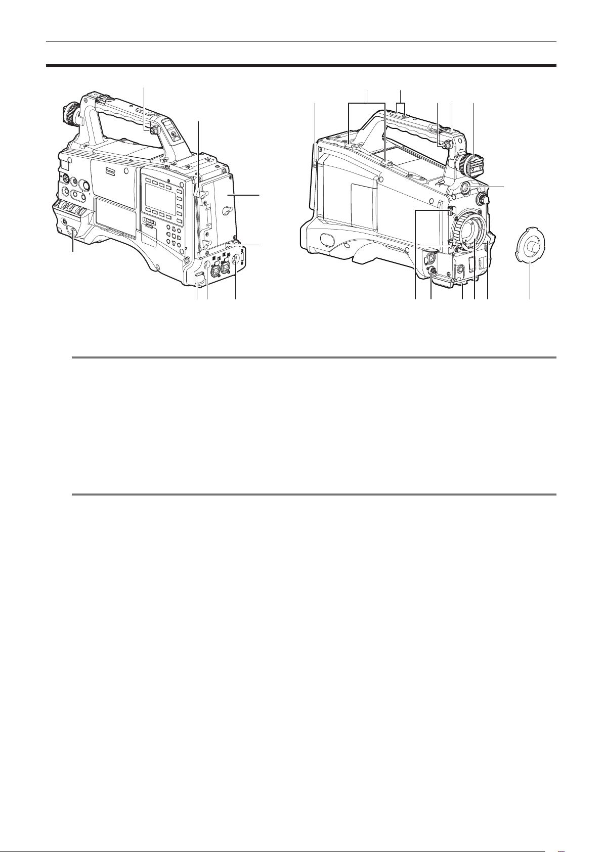
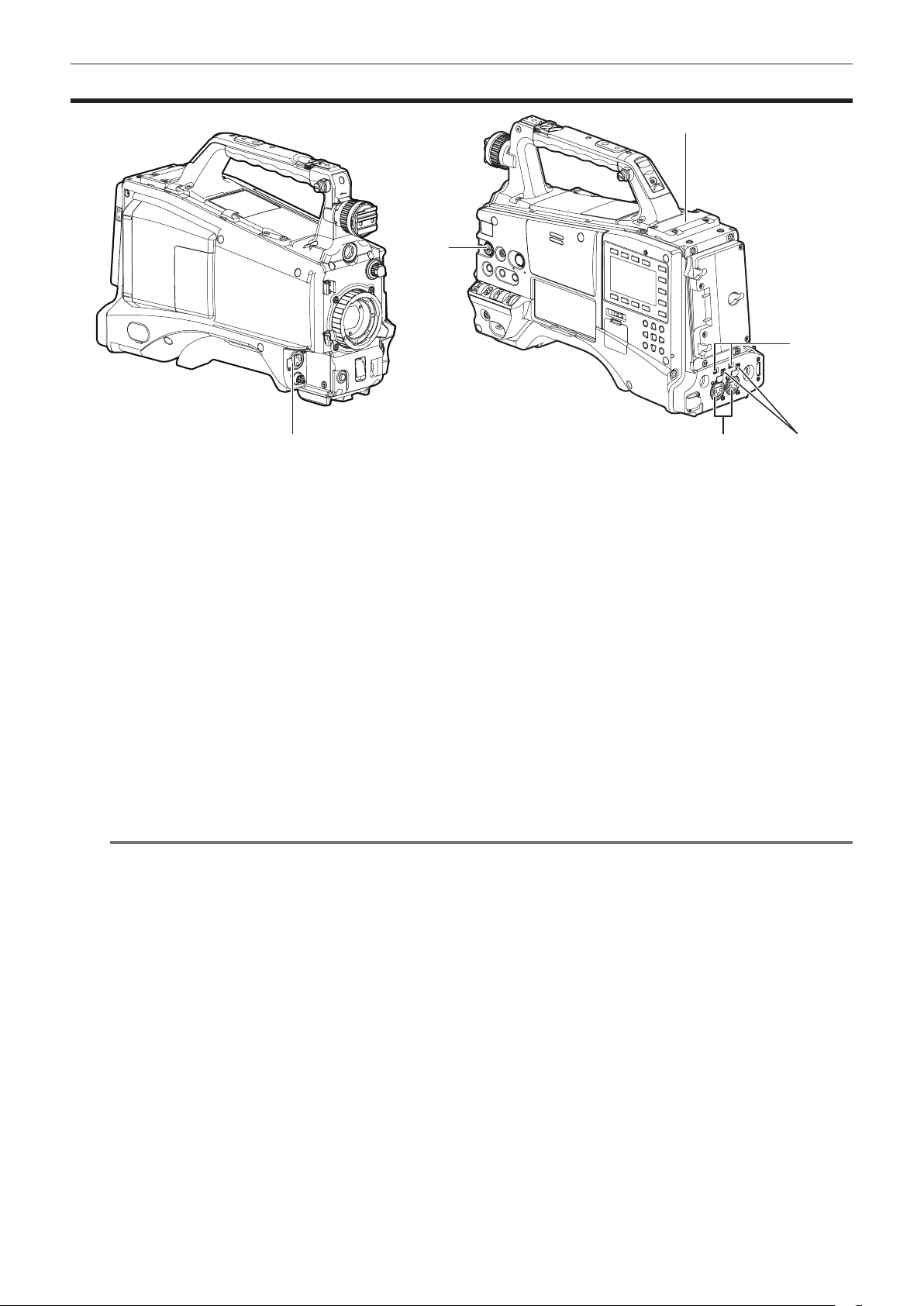
Power supply and accessory mounting section
9
10
1111128 13
2
3
14
4
1
5 6 7 2018171615
1 <POWER> switch (page 54)
Switch on/off the power.
NOTE
@@
t Even when the <POWER> switch is set to the <OFF> position, the camera is not shut off from the main power.
2 Battery release lever (page 28)
Pull this battery release lever down to release the battery.
3 Battery holder (page 28)
Mount the Anton/Bauer battery.
4 Light control switch (page 28)
5 <DC IN> terminal (page 29)
This is the external DC power supply input terminal. Connect to the external DC power supply.
6 <DC OUT> terminal (page 41)
This is the DC 12 V output terminal. It provides a maximum current of 1.5 A.
NOTE
@@
t When connecting external equipment to this terminal, rst fully check the polarities of the connection. Failure to do so may result in a malfunction.
7 <REMOTE> terminal (pages 183, 185)
Connect the remote control unit AJ-RC10G (optional) to remote-control some functions. For details, refer to “Connecting to the remote control unit
(AJ-RC10G)” (page 183).
Connect the extension control unit AG-EC4G (optional) to remote-control some functions. For details, refer to “Connecting to the extension control
unit (AG-EC4G)” (page 185).
8 Light output terminal
Connect the Ultralight 2 of Anton/Bauer (optional) or an equivalent video light of 50 W or under.
The battery charge level drops sharply when the light is illuminated. When using the light, using a battery of 90 Wh or more is recommended.
9 Cable holders
Used for clamping the light and microphone cables in place.
10 Accessory mounting holes
Attach accessories. Use only for the purpose of attaching accessories.
f Mounting hole size
- 1/4-20 UNC (screw length 10 mm or shorter)
- 3/8-16 UNC (screw length 10 mm or shorter)
11 Shoulder strap attachment tting (page 39)
Attach the shoulder strap.
12 Light shoe
Attach the video light.
Mounting hole size
f 1/4-20 UNC (screw length 6 mm or shorter)
13 Viewnder left-right positioning ring
To adjust the left/right position of the viewnder, loosen this ring, and slide the viewnder to the left or right to adjust it to an easy-to-view position.
Tighten the ring to clamp the viewnder in place after adjusting the viewnder.
14 <VF> terminal
Attach the viewnder AG-CVF15G (optional), etc.
19
– 15 –
Page 16

Chapter 2 Description of parts — Power supply and accessory mounting section
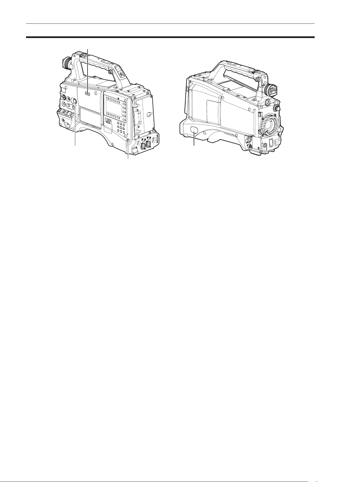
15 Lens cable/microphone cable clamp (page 31)
Used for securing the lens and microphone cables.
16 <LENS> terminal (page 31)
Connect the lens connection cable. For a detailed description of the lens used, refer to the Operating Instructions for the lens.
17 Tripod mount (page 39)
Attach the tripod adaptor SHAN-TM700 (optional) when mounting the camera on the tripod.
18 Lens mount (1/3 type bayonet) (page 31)
Mount the lens.
19 Lens lever (page 31)
After mounting the lens to the lens mount, tighten the lever to secure the lens.
20 Mount cap (page 31)
Raise the lens lever to remove the cap. Replace the cap when the lens is not mounted.
– 16 –
Page 17
Chapter 2 Description of parts — Audio (input) function section
Audio (input) function section
6
2
4
1
1 <MIC IN> terminal (page 37)
Connect the microphone (optional).
f The phantom microphone can also be used. To use this, set [ON] in the main menu → [AUDIO SETUP] → [INPUT SETTING] → [FRONT MIC
POWER]. When it is set to [ON] and a microphone is not connected, low frequency noise may occur. This is not a problem when a microphone is
connected.
2 <F.AUDIO LEVEL> dial (page 69)
Adjust the recording level of audio channels 1 to 4.
f Setting the audio level adjustment method to [MANU] on the [AUD02:INPUT] screen of SmartUI allows you to adjust the audio level of the voice
channel using this dial.
f You can use the main menu → [AUDIO SETUP] → [RECORDING CH SETTING] → [FRONT VR CH1], [FRONT VR CH2], [FRONT VR CH3], and
[FRONT VR CH4] to set the controls so that this operation can be done from any input terminal.
3 <AUDIO IN CH1/3>, <AUDIO IN CH2/4> terminal (page 38)
Connect the audio equipment or the microphone.
4 <LINE>/<MIC> switch (pages 38, 45)
Switch audio input signals connected to the <AUDIO IN CH1/3>/<AUDIO IN CH2/4> terminal.
<LINE>: Select when audio equipment is connected by the line input.
<MIC>: Select when the external microphone is connected.
5 Microphone input power switch (page 45)
Switch to supply power to the microphones connected to <AUDIO IN CH1/3> and <AUDIO IN CH2/4> terminals.
<+48V>: Supplies +48 V power to the microphone.
<OFF>: Does not supply power to the microphone.
NOTE
@@
t When microphone input <+48V> is set and microphones are not connected to the <AUDIO IN CH1/3> and <AUDIO IN CH2/4> terminals, low-
frequency noise may occur. This is not a problem when a microphone is connected.
6 Wireless slot (page 37)
Mount the UniSlot wireless microphone receiver (optional).
3 5
– 17 –
Page 18
Chapter 2 Description of parts — Audio (output) function section
Audio (output) function section
2
1 4
3
1 <MONITOR> dial
Adjust the volume of the speaker and earphones.
2 Internal speaker
During recording, EE audio can be monitored, and during playback, playback audio can be monitored.
Audio from the speaker automatically disappears when earphones are connected to the <PHONES> terminal.
3 <PHONES> terminal
This is the connecting terminal for audio monitor earphones (stereo mini-jack).
4 <AUDIO OUT> terminal(page 159)
Output audio signals recorded on audio channel 1/2 or 3/4.
f Select the output signal on the [AUD03:MONI] screen of SmartUI.
– 18 –
Page 19
Chapter 2 Description of parts — Shooting and recording/playback functions section
Shooting and recording/playback functions section
Shooting and recording (camera unit)
1
2 5 6 7 8 93 4
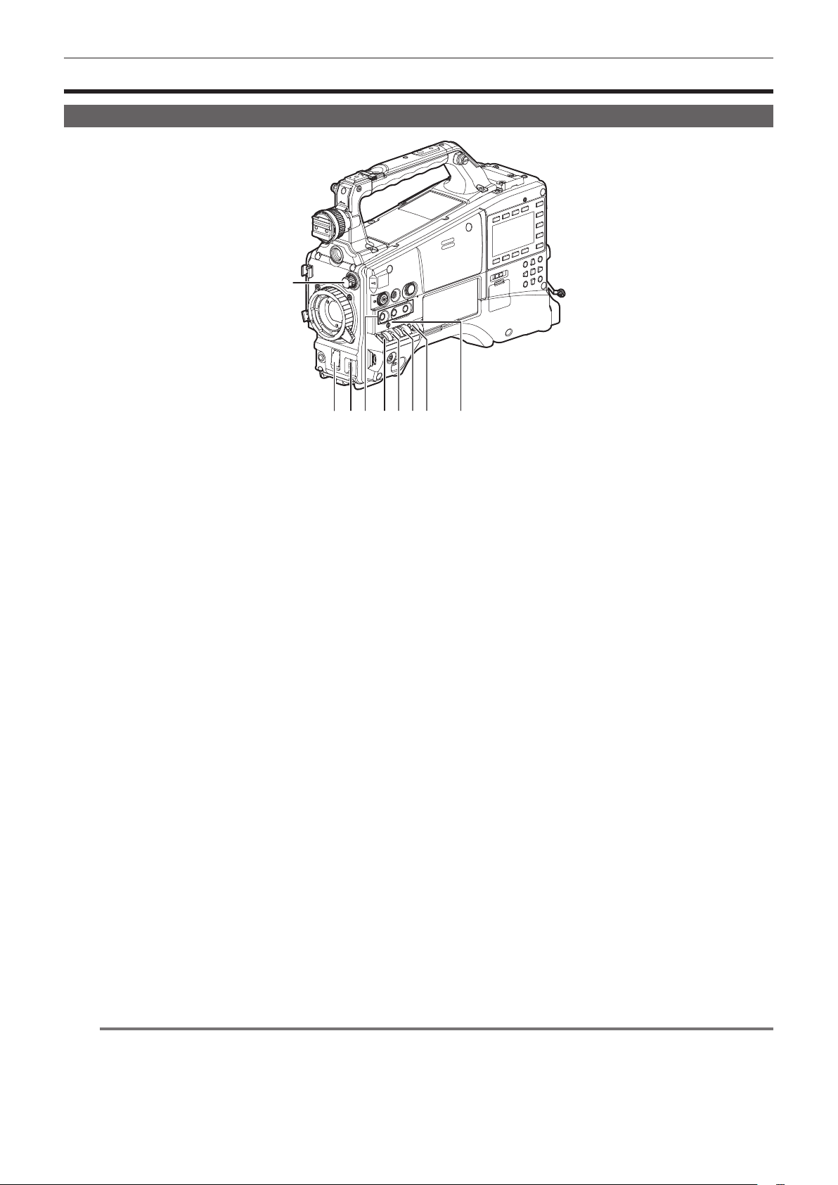
1 <ND FILTER> dial (page 55)
Select the lter to suit the brightness of the subject.
<1><CLEAR>: Does not use the ND lter.
<2><1/4ND>: Reduce the amount of light entering the MOS sensor to 1/4.
<3><1/16ND>: Reduce the amount of light entering the MOS sensor to 1/16.
<4><1/64ND>: Reduce the amount of light entering the MOS sensor to 1/64.
2 <SHUTTER> switch (page 64)
This is the electronic shutter switch.
<OFF>: Disables the electronic shutter.
<ON>: Enables the electronic shutter.
<SEL>: Changes the speed of the electronic shutter.
This switch is the spring switch. Each turn towards the <SEL> side alters the shutter speed.
3 <AUTO W/B BAL> switch (page 61)
<AWB>: Adjusts white balance automatically. When this switch is operated with the <WHITE BAL> switch on the side set to the <A> or <B> position,
white balance is adjusted in several seconds and the adjusted value is stored in memory. When the <WHITE BAL> switch is at the <PRST> position,
the value can be changed to the preset color temperature and user-specied variable value by setting the <AUTO W/B BAL> switch towards the
<AWB> side, and setting it once again towards the <AWB> side while the color temperature is displayed.
<ABB>: Adjusts black balance automatically.
4 USER (<USER MAIN>/<USER1>/<USER2> button) (page 67)
Assign user-selected functions to each button. Pressing each button performs the assigned function.
5 <DISP/MODE CHK> switch (page 108)
This is the spring switch to check the status of the shooting, etc.
f Push this towards the <OFF> side to clear all displays except viewnder operation status and frame displays such as the area display, and the
counter, marker, and safety zone displays.
f Push this towards the <CHK> side to display in the viewnder the setting status for all shooting functions, the list of functions assigned to the
USER button, etc. while on stand-by or while shooting. Pushing it to the <CHK> side again while information is displayed switches the display to
the next information page. The mode check information display disappears after approximately three seconds.
6 <GAIN> switch (page 61)
Switch the video amplier gain according to the brightness of the subject to shoot.
f The gain settings for the <L>/<M>/<H> positions can be changed using main menu → [SW MODE] → [LOW GAIN], [MID GAIN], and [HIGH GAIN].
f Factory settings are L=0 dB, M=6 dB, and H=12 dB.
7 <OUTPUT>/<AUTO KNEE> selector switch
Select the video signals output to the memory, viewnder and video monitor from the camera unit.
<CAM>/<ON>: Video captured with the camera is output and the auto knee function is activated. Instead of the auto knee function, the dynamic
range stretcher (DRS) function can be assigned.
<CAM>/<OFF>: Video captured with the camera is output and the auto knee function is not activated. The knee point is xed to the level set by
menu operations.
<BARS>/<OFF>: Color bars signal is output. The auto knee function is not activated.
NOTE
@@
t Auto knee function
When you adjust the levels to shoot people or scenery, etc. against a strongly lit background, the background will be totally whited out, and
buildings and scenery in the background will be blurred. In such a case, the auto knee function reproduces the background clearly.
The auto knee function is effective when shooting the following scenes:
- The subject is a person positioned in the shade under a clear sky.
- When shooting people in a vehicle or building as well as the background visible through a window at the same time.
– 19 –
Page 20

Chapter 2 Description of parts — Shooting and recording/playback functions section
- The subject is a high-contrast scene.
8 <WHITE BAL> switch (pages 61, 62)
Select the method for adjustment of the white balance.
<PRST>: Set the switch to this position when you have no time or are otherwise unable to adjust the white balance.
f The factory setting is 3200 K.
f The color temperature can be changed successively to 3200 K, 5600 K, and the user-specied variable value by setting the main menu → [SW
MODE] → [W.BAL PRESET], or by pushing the <AUTO W/B BAL> switch towards the <AWB> side, and pushing the <AUTO W/B BAL> switch
towards the <AWB> side again while the color temperature is displayed. The variable value can be set with the jog dial button. (page 62)
<A>/<B>: Pushing the <AUTO W/B BAL> switch towards the <AWB> side adjusts the white balance automatically and saves the adjusted value to
<A> or <B>.
f Selecting [Bch] from the main menu → [SW MODE] → [ATW] allows you to assign auto tracking white balance (ATW) function to <B>. (page 62)
9 Focal plane index <
Indicate the imaging plane inside the camera.
>
– 20 –
Page 21
Chapter 2 Description of parts — Shooting and recording/playback functions section
Shooting and recording/playback functions section (recording unit)
1
2
3
4
7
29
5
6
8 9
10 11 12 13
16
1 2
THUMBNAIL
EXIT
CANCEL BOTTOM
LIGHT
28
CAM
AUDIO
SETUP
HOME
27
26
25
24
SHIFT
23
MENU
0
-10
-18
-20
-30
dB
SET
TOP
MULTI SEL
14 15
17
18
19
20
HOLD COUNTER RESET MONITOR SEL
TC NDF SLAVE P -REC
MEDIA
CH1
A
E
F
CH2
BATT
E
F
/REW STOP FF/ PLAY/PAUSE
KEY LOCK
21 22
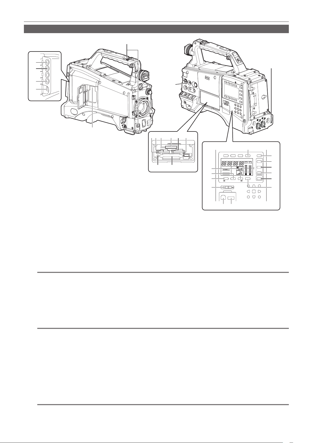
1 <REC> button (page 55)
Press this button to start recording. Press it again to stop recording.
This button has the same function as the VTR button on the lens side.
2 <SDI OUT1> terminal (page 83)
This is the output terminal for SDI signal. Output is performed in the same signal format as in the system mode. Down-conversion and up-conversion
are not supported.
3 <GL IN/VIDEO OUT> terminal (pages 103)
This is the input terminal for reference signals when setting the genlock to the camera unit. This is also the output terminal for the VBS signal for
monitor. Switch the setting using the main menu → [IN/OUT SEL] → [GL IN/VIDEO OUT SEL].
NOTE
@@
t Supply Y signal of HD or composite signals as the input signal. However, the sub-carrier of the composite signal on the camera cannot be
externally locked.
4 <SDI OUT2/IN> terminal (page 83)
This is the output terminal for the SDI signal for monitor. This is also the input terminal for SDI signal. Switch with the main menu → [IN/OUT SEL] →
[SDI OUT2/IN SEL]. Video independent from the <SDI OUT1> terminal can be output. Also, the HD SDI signal or the down-converted SD SDI signal
can be selected in the [SET02:MON OUT SELECT] screen of SmartUI. Cross-conversion and up-conversion are not supported.
5 <LAN> terminal (page 195)
Connect the LAN cable.
NOTE
@@
t For the cable to be connected to the <LAN> terminal, use the shielded cable.
6 <USB2.0> terminal (sub-host) (pages 193, 194)
Mount the wireless module AJ-WM30/AJ-WM50 (optional). Or, attach the USB 2.0 extension cable connecting the body and the 4G/LTE USB
modem (optional).
7 <FOCUS ASSIST> button (page 59)
Switch on/off the focus assist function.
8 microP2 memory card 1 access LED (page 48)
Indicate the access status of recording and playback of the card inserted in the microP2 memory card slot 1.
9 microP2 memory card slot 1 (page 47)
10 Busy (active status indication) lamp (page 92)
Indicate the active status of the SD memory card, and is illuminated when the card is active.
NOTE
@@
t Do not remove or insert the card while the lamp is lit. Doing so may damage the SD memory card.
– 21 –
Page 22

Chapter 2 Description of parts — Shooting and recording/playback functions section
11 SD memory card slot (page 91)
This is the insertion slot for the SD memory card (optional). Use the SD memory card for recording/opening the setting menu and scene les for the
camera, uploading metadata, or proxy recording, etc.
NOTE
@@
t Cautions when using SD memory cards
- On the camera, use SD memory cards that conform to the SD standard, SDHC standard, or the SDXC standard. To record the proxy data, use
SD, SDHC, or SDXC memory cards with an indication of class2 or higher.
If the recording format of the proxy data is [SHQ 2CH MOV] or [AVC-G6 2CH MOV], use a card of class4 or higher.
- MMC (Multi Media Card) cannot be used. (Bear in mind that taking pictures may no longer be possible if you use them.)
- When using miniSD/microSD cards with the camera, always install the adaptor specially designed for miniSD/microSD cards. (The camera will
not work properly if only the miniSD/microSD adaptor is installed. Make sure that the card has been inserted into the adaptor before use.)
- Use of Panasonic SD memory cards and miniSD/microSD cards is recommended. Be sure to format cards on the camera before use.
- Refer to our support desk at the following website for the latest information not included in these operating instructions.
http://pro-av.panasonic.net/
- SDHC memory cards are a standard that was established in 2006 by the SD Association for large-capacity memory cards that exceed 2 GB.
- SDXC memory cards are a standard that was established in 2009 by the SD Association for large-capacity memory cards that exceed 32 GB.
12 microP2 memory card 2 access LED (page 48)
Indicate the access status of recording and playback of the card inserted in the microP2 memory card slot 2.
13 microP2 memory card slot 2 (page 47)
14 P2 memory card access LED (page 48)
Indicate the access status of recording and playback of the card inserted in the P2 memory card slot.
15 P2 memory card slot (page 47)
16 <MONITOR SEL> button
Switch the audio channel that is output to the speaker, the <PHONES> terminal, and the <AUDIO OUT> terminal to [CH1/2] or [CH3/4] each time
you press the button. The channel display of the audio channel level meter is switched together.
When a screen other than the [HOME] screen of SmartUI is displayed, the function corresponding to each setting screen is performed.
17 <FF/)> button
Press this button during a pause to perform fast playback.
Press this button during playback to perform 4x speed playback.
If it is pressed with playback paused, the clip being played back is paused at the start point of the next clip (cued state).
When a screen other than the [HOME] screen of SmartUI is displayed, the function corresponding to each setting screen is performed.
18 <STOP> button
Press this button to stop playback.
Press this button when you stop interval recording or one-shot recording, or when you end combining to the clip of one-clip recording.
When a screen other than the [HOME] screen of SmartUI is displayed, the function corresponding to each setting screen is performed.
19 <%/REW> button
Press this button during a pause to perform fast-reverse playback.
Press this button during playback to perform 4x speed reverse playback.
If it is pressed with playback paused, the clip being played back is paused at its start point (cued state).
When a screen other than the [HOME] screen of SmartUI is displayed, the function corresponding to each setting screen is performed.
20 <KEY LOCK> switch (page 156)
Disable button operations related to SmartUI and thumbnail operations. However, <LIGHT> button operation is available.
21 <USB2.0> terminal (device) (page 175)
22 <USB2.0> terminal (host) (page 175)
Connect the USB 2.0 cable.
Setting to [ON] using main menu → [NETWORK SETUP] → [USB MODE] allows you to transfer data using USB 2.0.
In this state, recording/playback and clip operations on the camera are limited.
23 <PLAY/PAUSE> button
Press this button to view playback image.
Press it during playback to pause playback.
When a screen other than the [HOME] screen of SmartUI is displayed, the function corresponding to each setting screen is performed.
24 <HOME> button (page 156)
Display the [HOME] screen on SmartUI.
25 <SETUP> button (page 161)
Display the [SETUP] screen on SmartUI.
26 <AUDIO> button (page 159)
Display the [AUDIO] screen on SmartUI.
27 <CAM> button (page 159)
Display the [CAMERA] screen on SmartUI.
28 <LIGHT> button
Control lighting of SmartUI. Each press turns the light of the SmartUI on and off.
29 <HDMI> terminal (page 83)
This is the output terminal of the video for monitor.
– 22 –
Page 23
Chapter 2 Description of parts — Menu operation section and thumbnail operation section
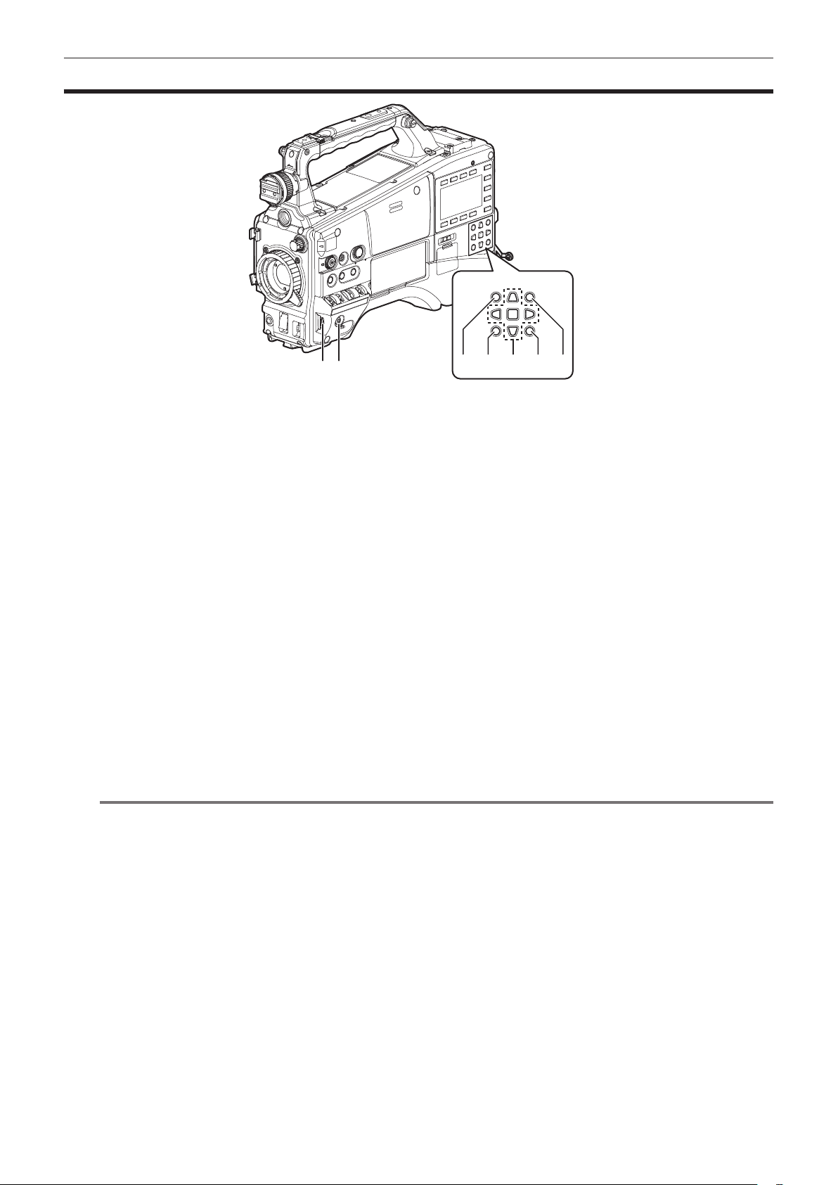
Menu operation section and thumbnail operation section
3
21
1 Jog dial button (page 129)
f When the setting menu is displayed, navigate through the setting menu pages to select and set items. Turning the jog dial button toward the bottom
moves the cursor toward the bottom. Turning it toward the top moves the cursor toward the top. Press the jog dial button to x the settings.
f When the setting menu is not displayed, the following operation allows you to adjust the synchro scan speed. Press the <SHUTTER> switch from
the <ON> position towards the <SEL> side several times to display the shutter speed in highlight and adjust using the jog dial button in synchro
scan mode. (page 65)
2 <MENU> button (page 129)
Press this button to display [USER MENU]. Press this button for 3 seconds or more to display the main menu. Press it again to return to the original
image.
During recording, button operation is disabled.
This button functions in the same way as the <THUMBNAIL MENU> button.
3 <THUMBNAIL> button (page 112)
Press the button to display the thumbnail screen on the viewnder and the monitor screen connected to the camera. Button operations are disabled
during recording and playback.
4 <EXIT>/<CANCEL> buttons (pages 114, 129)
Restore the display to the previous state while the setting menu or property screen is displayed.
Press this button while holding down the <SHIFT> button to act as the cancel button. This is convenient, for example, for batch-canceling clip
selections.
5 Cursor/<SET> button (pages 114, 129)
Operate the setting menu and thumbnails.
The four triangular buttons are cursor buttons and the square button in the center is the <SET> button.
6 <THUMBNAIL MENU> button
Press this button to display [USER MENU]. Press this button for three seconds or more to display the main menu. Press it again to return to the
original image.
During recording, button operation is disabled.
This button functions in the same way as the <MENU> button.
NOTE
@@
t Use the cursor/<SET> button and the <EXIT>/<CANCEL> buttons to select thumbnails or operate menus. (page 114)
7 <SHIFT> button (pages 114, 129)
Use this button while using other buttons at the same time. Operations with the <SHIFT> button held down are displayed in orange at the bottom of
each button.
f Press the cursor button (`/{) while holding down the <SHIFT> button.
This moves the cursor to the thumbnail of the clip at the start or the end on the thumbnail screen.
f Press the <SET> button while holding down the <SHIFT> button
This selects all clips from the previously selected clip up to the clip at the cursor position.
f Press the <EXIT>/<CANCEL> buttons while holding down the <SHIFT> button.
This works as the cancelation function.
4 5 6 7
– 23 –
Page 24
Time code section
1
Chapter 2 Description of parts — Time code section
432
1 2
THUMBNAIL
SET
0
-10
-18
-20
-30
dB
TOP SHIFT
LIGHT
CAM
AUDIO
SETUP
HOME
HOLD COUNTER RESET MONITOR SEL
TC NDF SLABE P -REC
MEDIA
CH1
A
E
F
CH2
BATT
E
F
/REW STOP FF/ PLAY/PAUSE
KEY LOCK
1 <TC IN/OUT> terminal (page 97)
This is the input/output terminal for time code.
f Switch input/output using the main menu → [IN/OUT SEL] → [TC IN/OUT SEL].
f Input the reference time code to this terminal when the time code is locked.
f Connect to the time code input terminal of the external device when locking the time code of the external device to the time code on the camera.
(page 105)
2 <HOLD> button
The time data indication on the counter display area is retained for the duration that this button is held down. However, the time code generator
continues to advance. Press again to release retained state.
This function is used to learn the time code or counter value of a particular recorded scene.
When a screen other than the [HOME] screen of SmartUI is displayed, the function corresponding to each setting screen is performed.
3 <COUNTER> button (page 101)
Each press of the button displays the counter value, time code, user bits, and VITC user bits information on the viewnder.
When a screen other than the [HOME] screen of SmartUI is displayed, the function corresponding to each setting screen is performed.
4 <RESET> button
Reset the counter value of the time code display.
When a screen other than the [HOME] screen of SmartUI is displayed, the function corresponding to each setting screen is performed.
– 24 –
Page 25
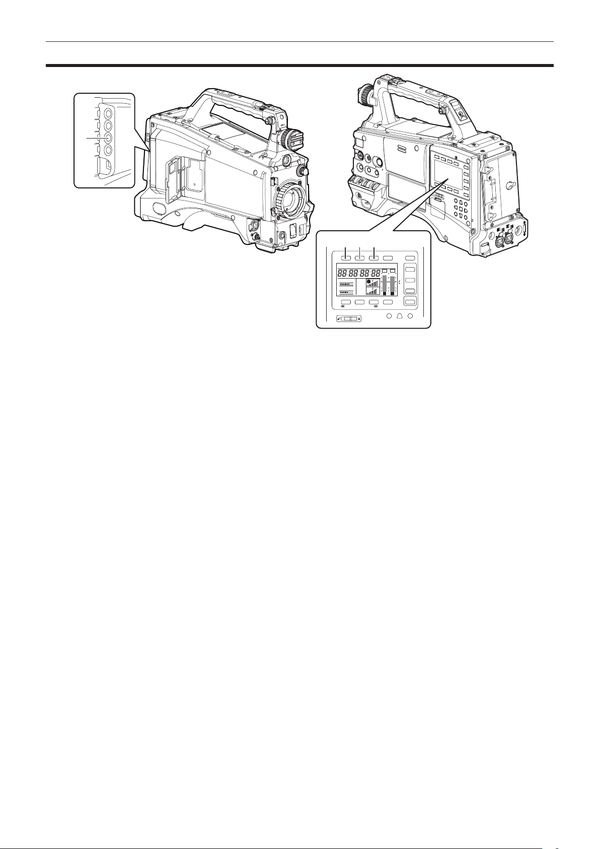
Chapter 2 Description of parts — Warning and status display section
Warning and status display section
431
2
1 Back tally lamp
When the back tally switch is set to <ON>, the lamp acts in the same way as the front tally lamp at the viewnder.
2 Rear tally lamp
When the back tally switch is set to <ON>, the lamp acts in the same way as the back tally lamp.
3 Back tally switch
Controls the operation of the battery tally lamp and rear tally lamp.
<ON>: Enables the back tally lamp and the rear tally lamp.
<OFF>: Disables the back tally lamp and the rear tally lamp.
4 <WARNING> lamp (page 213)
Starts ashing or is illuminated if something unusual occurs in the memory.
– 25 –
Page 26

Chapter 2 Description of parts — SmartUI display ([HOME] screen)
SmartUI display ([HOME] screen)
4
5
TCG NDF SLAVE P -REC
3
1
2
1 Media remaining space indicator bar
Displays the remaining free space in the P2 card using a 7-segment display.
Each segment is equivalent to three minutes, and the decreasing P2 card remaining time is indicated by the segments going out one segment at a
time.
2 Battery charge level indicator bar
When a battery with a digital indication (% indication) is used, all seven segments up to the F position light if the battery charge level is 70% or
higher.
When the battery charge level falls below 70%, the segments go out one by one for each 10% drop.
3 Audio channel level meter
One segment indicates 2 dB increment, with the smallest indication being −34 dB and the [OVER] indication displayed by r at the topmost position.
Each time you press the <MONITOR SEL> button, it switches between [CH1]/[CH2], stereo, [CH3]/[CH4], and the channel display of the level meter
is switched along with it. (page 159)
Channels output to the monitor audio are displayed in white dropout.
When the stereo is selected, both channels are displayed in white dropout.
4 Time code indications
Each time you press the <COUNTER> button, the display changes in the order of [COUNTER]/[CLIP] → [TCG[R]] → [UBG[R]] → [VUBG[R]] →
[COUNTER]/[CLIP] (not displayed in viewnder)* → [COUNTER]/[CLIP].
* The time code on the viewnder is not displayed.
[COUNTER]/[CLIP]: Displays the counter in hours:minutes:seconds. When [TOTAL] is selected from the main menu → [DISPLAY SETUP] → [REC
COUNTER], [COUNTER] is displayed. When [CLIP] is selected, [CLIP] is displayed.
[TCG[R]]: Displays the time code value in hours:minutes:seconds:frame.
[UBG[R]]: Displays the user bits value.
[VUBG[R]]: Displays the user bits value of VITC.
[NDF]: Indicates when the time code is in the non-drop frame mode.
[DF]: Indicates when the time code is in the drop frame mode.
[HOLD]: Indicates when the time code generator/reader value is held.
[F-RUN]: Indicates when the time code is set to advance continuously regardless of the recording operation.
[R-RUN]: Indicates when the time code is set to advance only during recording.
[SLAVE]: Indicates when the time code is externally locked.
5 Recording mode display
[REC]: Standard recording
[P-REC]: Pre-recording
[I-REC]: Interval recording
[L-REC]: Loop recording
[S-REC]: Simultaneous recording
6 Status information
Audio level display: Indicates whether audio [CH1]/[CH3] or [CH2]/[CH4] audio volume and audio level are in auto adjustment mode. In the auto
adjustment mode, [A] is displayed.
Audio input: Indicates audio [CH1], [CH2], [CH3], and [CH4] input settings.
When USB connected: Indicates when the main menu → [NETWORK SETUP] → [USB MODE] is set to [ON] and the device selected using [USB
MODE SELECT] is connected.
f In the USB host mode: [USB STORAGE CONNECTED]/[USB STORAGE DISCONNECTED]
f In the USB device mode: [USB DEVICE CONNECTED]/[USB DEVICE DISCONNECTED]
Error, card warning display: Indicates the error code when something has caused an error in the camera.
MEDIA
E
BATT
E
F
F
CH1
CH2
A
1 2
6
– 26 –
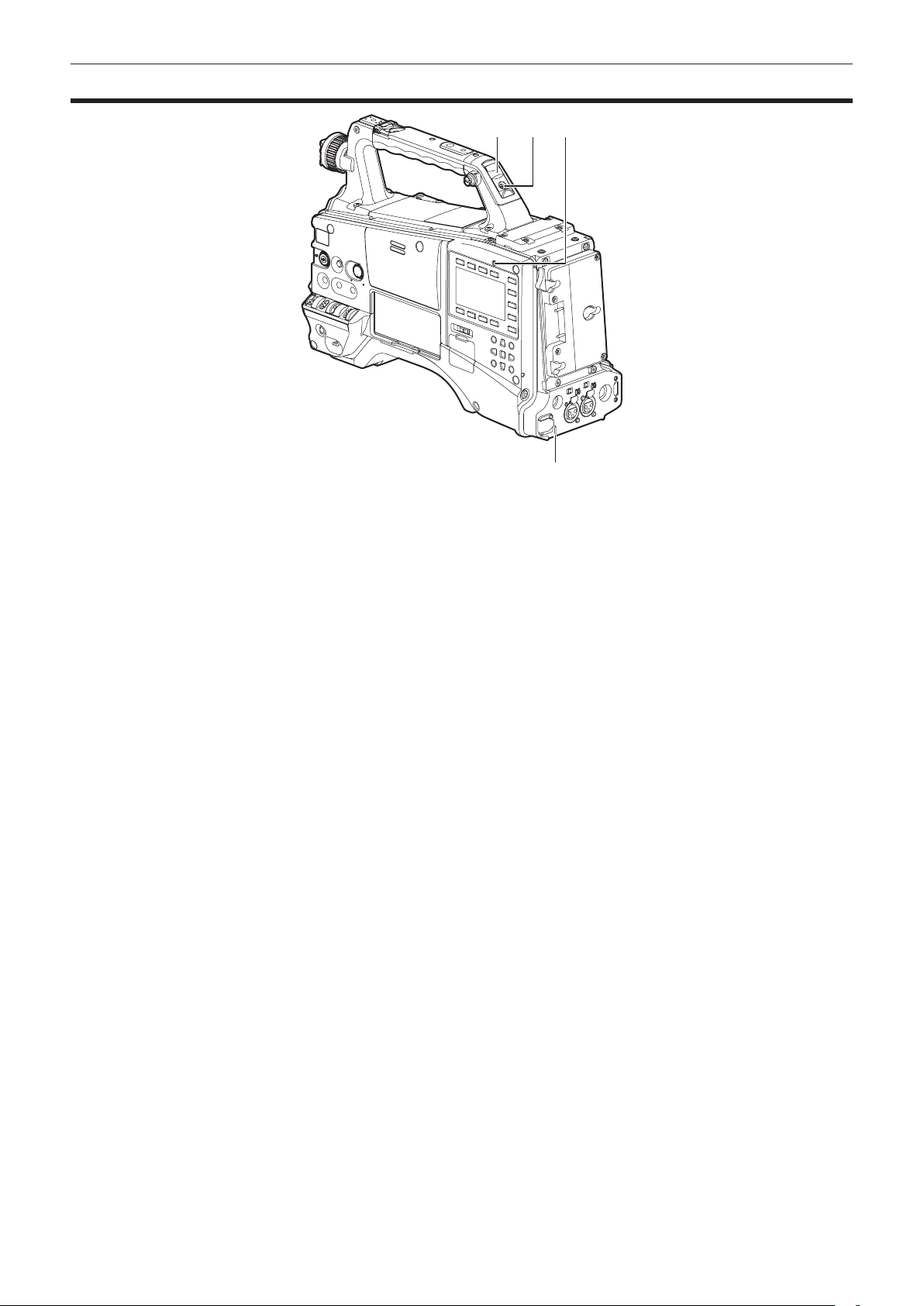
Page 27

Chapter 3 Preparation
Before you use the camera, mount the battery and lens following the procedures in this chapter. The mounting of accessories is also described in this
chapter.
Page 28
Chapter 3 Preparation — Power supply
Power supply
A battery or external DC power supply can be used as the camera’s power supply.
Using batteries
Connection of the following batteries to the camera has been veried.
r Anton/Bauer batteries
HYTRON140
DIONIC HC
r IDX batteries
ENDURA10
r PAG batteries
PAG L96e
NOTE
@@
t Other batteries can be used by changing [BATTERY SELECT] using the main menu → [BATTERY SETUP]. Use of batteries that are already veried
as connectable to the camera is recommended.
t Before you use a battery, charge it with a battery charger. (For details on charging, refer to each operation instructions.)
Mounting and setting battery
Using Anton/Bauer batteries
Power supply output terminal for lighting
Anton/Bauer batteries
Light control switch
Mount the Anton/Bauer battery.
1
Insert the battery terminal and slide in the direction of the arrow.
2
Set the battery type.
3
Select the type of battery from the main menu → [BATTERY SETUP] → [BATTERY SELECT].
For details, refer to “Setting menu basic operations” (page 129).
NOTE
@@
t The Anton/Bauer battery holder includes both a power supply output terminal for lighting and a light control switch, which are convenient when
installing light. Contact Anton/Bauer, Inc. for details on lighting systems.
t To remove the battery, keep the release lever of the battery holder completely down, slide the battery in the opposite direction of when you mounted it.
Release lever
– 28 –
Page 29
Chapter 3 Preparation — Power supply
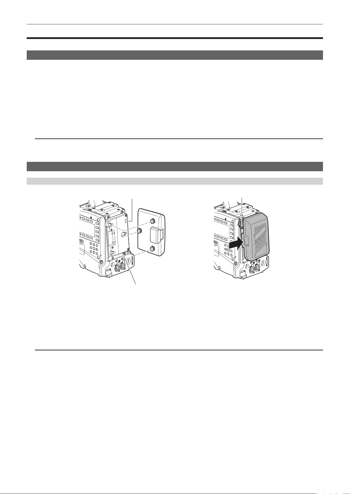
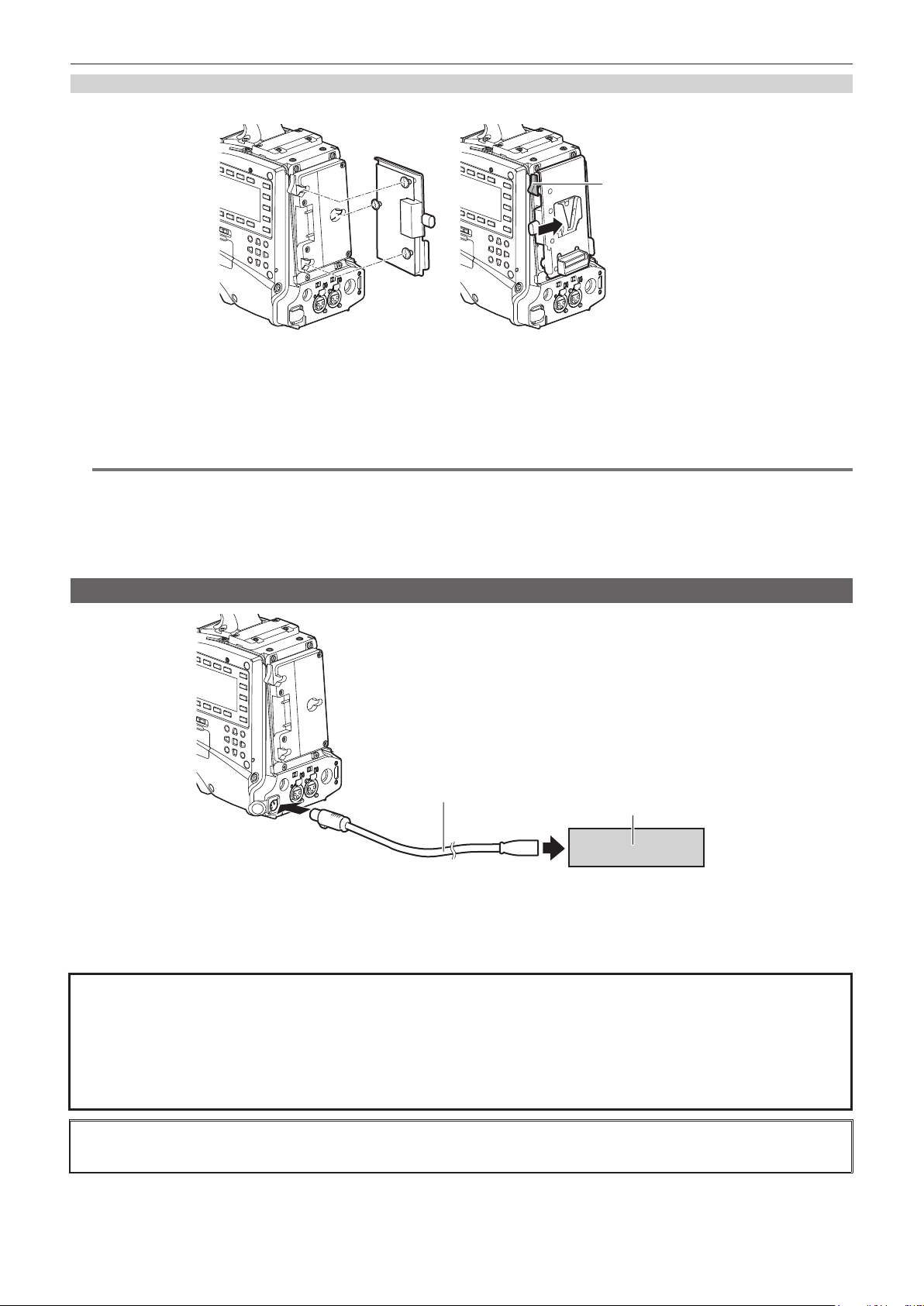
Using V-mount type batteries
Mount the V-mount type battery plate. As shown in the gure, insert and slide in the direction of the arrow.
Release lever
Mount the V-mount type battery plate.
1
Slide in the direction of the arrow.
2
Set the battery type.
3
f Select the type of battery from the main menu → [BATTERY SETUP] → [BATTERY SELECT].
NOTE
@@
t Contact your dealer for information about the V-mount type battery plate.
t When the V-mount type battery plate is used, % (percent) is not displayed even if batteries with a battery level indicator function are used.
t When removing the plate, remove by sliding the release lever.
t When using a battery that is not in the [BATTERY SELECT] item, set [TYPE A], [TYPE B], or [TYPE C], and set each item according to the
characteristics of the battery.
For details, refer to [BATTERY SETUP] (page 150).
Using external DC power supply
DC cable
<DC IN> terminal
Connect the <DC IN> terminal of the camera to the external DC power supply.
1
Turn on the <POWER> switch of the external DC power supply (if the external DC power supply has a <POWER> switch).
2
Turn the camera’s <POWER> switch to <ON>.
3
r External DC power supply
Connect after making sure that the output voltage of the external DC power supply is compatible with the rated voltage of the camera.
Select an output amperage for the external DC power supply with a margin above the total amperage of the connected devices.
The total amperage of connected devices can be calculated with the following formula.
Total power consumption ÷ voltage
When the power of the camera is turned on, inrush current is generated. Insufcient power supply when turning on the power may cause a malfunction. We
recommend that you use an external DC power supply that can assure double the capacity of the total power consumption of the camera and connected devices
that are turned on by interlock when the power of the camera is turned on (such as lenses, wireless microphone receivers). For the DC cable, use a dual-core
shielded cord of AWG18 (nominal cross section area 0.824 mm
2
) or thicker.
External DC power supply
f Make sure of the pin alignment of the DC output terminal of the external DC power supply and the camera <DC IN> terminal, and connect the polarity
correctly.
If the +12 V power supply is mistakenly connected to the GND terminal, it may cause re or malfunction.
– 29 –
Page 30

Chapter 3 Preparation — Power supply
DC IN
1 GND
2 NC
3 NC
4
Manufacturer Parts No.: HA16RX-4P (SW1) (76) (Hirose Electric Co.)
NOTE
@@
t When both the battery and the external DC power supply are connected, the power supply from the external DC power supply has priority. The battery
may be removed while using the external DC power supply.
t When using an external DC power supply, be sure to turn the camera’s <POWER> switch to <ON> after turning on the <POWER> switch of the
external DC power supply. If the operations are performed in reverse, the camera may malfunction because the external DC power supply output
voltage rises too slowly.
t When power is supplied from the <DC IN> terminal, the light circuit does not function. The light circuit can be used only when power is supplied from
the Anton/Bauer battery plate.
t When connecting the battery to the <DC IN> terminal, set the type of battery using the main menu → [BATTERY SETUP] → [EXT DC IN SELECT]. In
this case, the remaining battery level is not displayed with % even when the battery has the battery level indicator function.
Panasonic Parts No.: K1AA104H0038
+12 V
– 30 –
Page 31

Chapter 3 Preparation — Mounting and adjusting the lens
Mounting and adjusting the lens
Mounting the lens
Mount cap
Lens lever
Fig. 1
Mark
Fig. 2
Cable clamp
<LENS> terminal
Fig. 3
Raise the lens lever and remove the mount cap. (Fig. 1)
1
Align the indentation at the top center of the lens mount with the center mark of the lens to mount the lens. (Fig. 2)
2
Lower the lens lever to firmly clamp the lens. (Fig. 3)
3
Secure the cable through the cable clamp and connect it to the <LENS> terminal. (Fig. 4)
4
Perform lens flange back adjustments.
5
For details, refer to “Lens ange back adjustment” (page 31).
NOTE
@@
t For handling the lens, refer to the lens operating instructions.
t For details on the current from the <LENS> terminal, refer to “Details of the connector signals” (page 223).
t When the lens is removed, install the mount cap to protect the device.
Fig. 4
Lens ange back adjustment
If images are not clearly focused at both telephoto and wide-angle positions during zoom operations, adjust the lens ange back (distance from the lens
mounting surface to the image formation surface).
Once adjusted, the lens ange back does not need to be readjusted until the lens is changed.
NOTE
@@
t Refer to the lens operating instructions for guidance on adjustment methods and positions of lens parts.
– 31 –
Page 32

Chapter 3 Preparation — Mounting and adjusting the lens
For a normal lens
Approximately 3 m
Mount the lens on the camera.
1
Make sure to connect the lens cable.
Set the lens aperture to manual, and fully open the iris.
2
Place the lens flange back adjustment chart approximately 3 m from the lens and adjust the lighting on the chart to obtain an
3
appropriate image output level.
If the image level is too high, use the lters or the shutter.
Loosen the F.f (Flange focus) ring clamping screw.
4
Set the zoom ring to the telephoto end position, either manually or by electric drive.
5
Aim the lens at the lens flange back adjustment chart and turn the distance ring to bring the chart into focus.
6
Set the zoom ring to the wide-angle end position and turn the F.f (Flange focus) ring to bring into focus.
7
At this time, do not move the distance ring.
Repeat steps 5 to 7 until the lens is in focus at both the telephoto and wide-angle positions.
8
Firmly tighten the F.f (Flange focus) ring clamping screw.
9
NOTE
@@
t F.b (Lens ange back) ring may be indicated on some lenses as the F.f (lens ange focus) ring.
For an auto-focus compatible lens
If an auto-focus compatible lens is used, perform the following procedure to operate zoom and focus automatically and adjust the lens ange back.
Approximately 3 m
Mount the lens on the camera.
1
Turn the <POWER> switch of the camera to <OFF> before mounting the lens.
Make sure to connect the lens cable.
Set the lens iris to manual, and fully open the iris.
2
Place the lens flange back adjustment chart approximately 3 m away from the lens and adjust the lighting on the chart to obtain
3
an appropriate image output level.
Do not place other subjects near the adjustment chart.
Set the <ZOOM> switch of the lens to the <SERVO> side. (Electric zoom mode)
4
Change the setting menu of the camera to adjust the lens flange back.
5
1) Select [EXECUTE] in the main menu → [MAINTENANCE] → [LENS ADJ.] → [FB ADJ.].
2) Select [YES] using the jog dial button, and then press the jog dial button.
The [ACTIVE...] message is displayed on the viewnder screen during the adjustment.
– 32 –
Page 33

Chapter 3 Preparation — Mounting and adjusting the lens
The [FB ADJ. OK!] message is displayed on the viewnder screen when the adjustment has completed.
The [FB ADJ. ERROR!] message is displayed on the viewnder screen when the adjustment has not been performed correctly. In such a case,
check the conditions of the subject and lighting, open the iris again, and perform adjustment again.
White shading compensation
Three optionally adjustable data items ([L1:LENS1], [L2:LENS2], and [L3:LENS3]) can be used for white shading compensation with the camera.
Shading compensation is not performed when set to [OFF].
Selecting white shading data
Select [L1:LENS1], [L2:LENS2], [L3:LENS3], or [OFF] using main menu → [MAINTENANCE] → [WHITE SHADING] → [SHADING
1
SELECT].
With factory settings, no compensation data is stored in [L1:LENS1], [L2:LENS2], and [L3:LENS3].
The title of the white shading data can be changed using the setting menu. (page 34)
Adjusting the white shading
Fig. 1
Set the camera for adjustment.
1
1) Mount the lens on the camera.
f Make sure to connect the lens cable.
2) Set the <SHUTTER> switch to <OFF>, and the <GAIN> switch to <L> (0 dB).
3) If the lens is equipped with an extender function, release the extender function.
4) Make sure it is set to either [L1:LENS1], [L2:LENS2], or [L3:LENS3] using main menu → [MAINTENANCE] → [WHITE SHADING] → [SHADING
SELECT].
5) Select [EXECUTE] using main menu → [MAINTENANCE] → [WHITE SHADING].
f The [CHECK LUMINANCE LEVEL. ZEBRA ON EVF.] message is displayed on the screen. (Fig. 1)
Set the screen.
2
1) Shoot a white sheet of paper with no unevenness of color for the whole screen.
2) Set the lens aperture to manual, and adjust it so that the zebra pattern covers the whole viewfinder screen.
f Make sure that the lens aperture control is between F4 to F11.
f Adjust the position of the lighting because the zebra pattern will not cover the whole screen if there is any unevenness in the lighting.
f Make adjustments to avoid several light sources of different color temperature (e.g. uorescent lights and halogen lamp) from illuminating on
the white paper.
Adjust the white balance/black balance.
3
1) Set the <WHITE BAL> switch to <A> or <B>, and use the <AUTO W/B BAL> switch to adjust white balance automatically (AWB).
2) Use the <AUTO W/B BAL> switch to adjust black balance automatically (ABB).
3) Use the <AUTO W/B BAL> switch to adjust white balance automatically (AWB) again.
Repeat steps 2-2).
4
Adjust white shading.
5
1) Select [YES] and press the jog dial button.
f The [ACTIVE...] message is displayed on the screen during the adjustment.
f When the adjustment is complete after a few seconds, the [WHITE SHADING OK!] message is displayed.
f If an error message such as [WHITE SHADING ERROR!], [LEVEL OVER], [WHITE SHADING ERROR!], or [LOW LIGHT] appears, readjust
the iris.
f The adjusted value is automatically stored in the selected memory ([L1:LENS1], [L2:LENS2], or [L3:LENS3]).
– 33 –
Page 34

Chapter 3 Preparation — Mounting and adjusting the lens
If the lens is equipped with an extender function, enable the extender function and repeat steps 2 to 5.
6
Adjusted values are stored on the camera as a single lens correction data including two ways for when the lens is equipped and not equipped with a
lens extender.
Adjustment values are saved in memory, so there is no need to re-adjust white shading even after turning the camera off.
NOTE
@@
t Coloring may occur in the vertical direction near where the lens aperture is open (OPEN) even when the white shading has been adjusted, but this is
something that is inherent to optical systems. This is not a malfunction.
t When white shading adjustment is performed while image is being disturbed due to the genlock, adjustment may not be performed correctly. Try white
shading adjustment again after the image returns to normal.
t Since uorescent lights, mercury lamps, and other such kinds of lighting tend to icker, use a light source which is less subject to ickering such as
sunlight or a halogen lamp.
t Make sure to leave the <SHUTTER> switch at <OFF>.
Changing the white shading data title
Select the white shading data which title you want to change in the main menu → [MAINTENANCE] → [WHITE SHADING] →
1
[SHADING SELECT], and press the <SET> button (or the jog dial button).
In the main menu → [MAINTENANCE] → [WHITE SHADING] →, select [NAME EDIT].
2
The title entry screen and keyboard are displayed.
Enter the characters you want to set on the keyboard using cursor buttons (or the jog dial button).
3
Select [OK] and press the <SET> button (or the jog dial button).
4
The title is updated.
Chromatic aberration compensation function (CAC)
The chromatic aberration compensation function minimizes color smearing in peripheral images. This function automatically compensates for
registration error that is caused mainly due to slight chromatic aberration, which is hard to completely compensate with the lens itself, using the camera
recorder unit.
When the lens compatible with the chromatic aberration compensation function is mounted, if the camera has the chromatic aberration compensation
data of the lens, then the chromatic aberration compensation function is activated automatically.
What is lens chromatic aberration?
B
G
R
“Chromatic aberration” here refers to zoom factor chromatic aberration. Zoom factor chromatic aberration occurs since the diffraction ratio of a lens
differs according to red (R)/green (G)/blue (B). Chromatic aberration on the lens itself is compensated for, but still remains in the periphery, in particular.
Also, this chromatic aberration occurs on zoom lens due to a complex relationship between zoom ratio, iris and focal distance. In image terms, this is
registration error.
Chromatic aberration compensation function
To compensate chromatic aberration, store the chromatic aberration characteristics of the lens regarding zoom ratio, iris and focal distance to the
camera recorder beforehand. Connect a lens that matches those chromatic aberration characteristics, and perform compensation matched to the zoom
ratio, iris and focal distance of that lens.
The following type of chromatic aberration compensation function data for lenses is stored in the camera before it is shipped.
Display on the camera Corresponding lens parts number
XT17X4.5BRM-K14 XT17x4.5BRM-K14
NOTE
@@
t For details on additions and modications to lenses compatible with the chromatic aberration compensation function, visit the support desk at the
following website:
http://pro-av.panasonic.net/
– 34 –
Page 35

Chapter 3 Preparation — Mounting and adjusting the lens
Operation of chromatic aberration compensation function
Operate by the following procedure when lens data is already stored on the camera.
Mount the lens on the camera, and connect the lens connector to the camera.
1
Set to [ON] using main menu → [MAINTENANCE] → [CAC ADJ.] → [CAC CONTROL].
2
If the lens model number stored on the camera matches the model number of the connected lens, the chromatic aberration data stored on the
camera will automatically be read.
Checking the operating status of the chromatic aberration compensation function
Push the <DISP/MODE CHK> switch towards the <CHK> side five times.
1
The mode check [CAC INFO] screen is displayed.
If [CAC CONT] is displayed as [ON] in the [CAC INFO] screen, the chromatic aberration compensation function is in operation. If other than [ON] is
displayed, the chromatic aberration compensation function is not in operation.
Also, if [CAC ACTIVE] is displayed in the SmartUI [CAM01:STATUS] screen, the chromatic aberration compensation function is in operation. If other
than [CAC ACTIVE] is displayed, the chromatic aberration compensation function is not in operation.
Loading the chromatic aberration compensation le from the SD memory card
Fig. 1 Fig. 2
Insert the SD memory card written with the chromatic aberration compensation data you downloaded from our website into the
1
camera.
For details on downloading, refer to the following website.
http://pro-av.panasonic.net/
Select [LOAD] in the main menu → [CARD FUNCTIONS] → [CAC FILE]. (Fig. 1)
2
The list of CAC les on the SD memory card is displayed.
Select the file number to load, and press the jog dial button (or <SET> button). (Fig. 2)
3
A conrmation screen is displayed.
Select the file number to save, and press the jog dial button (or <SET> button).
4
A conrmation screen is displayed.
Select [YES], and press the jog dial button (or <SET> button).
5
The CAC les are loaded to camera memory.
To store multiple chromatic aberration compensation data files in the camera repeat steps 2 to 5.
6
To end menu operations, press the <MENU> button.
7
The setting menu disappears, and the camera status display is returned to.
NOTE
@@
t Up to 32 les can be loaded to the camera.
To load a new le, delete any le before loading the new le.
For details, refer to “Deleting the chromatic aberration compensation le from the camera” (page 36).
– 35 –
Page 36
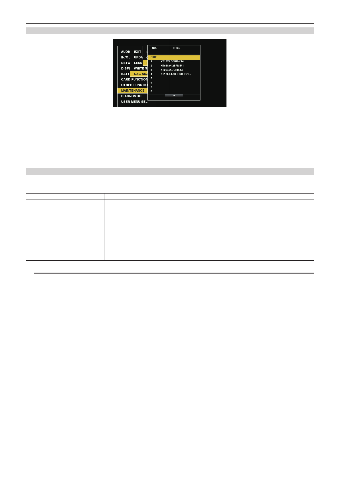
Chapter 3 Preparation — Mounting and adjusting the lens
Deleting the chromatic aberration compensation le from the camera
Fig. 1
Set to [OFF] using main menu → [MAINTENANCE] → [CAC ADJ.] → [CAC CONTROL].
1
In [LIST/DELETE], select the lens part no. you want to delete and press the jog dial button (or the <SET> button). (Fig. 1)
2
A conrmation screen is displayed.
Select [YES], and press the jog dial button (or <SET> button).
3
The le is deleted.
When the chromatic aberration compensation data is not functioning properly
When the chromatic aberration compensation function is not functioning properly, or when the chromatic aberration compensation data could not be
loaded normally, the viewnder displays an error message.
Error message Meaning Remedy
[CAC FILE DATA NOT FOUND] There is no chromatic aberration compensation data
matching the connected lens when the chromatic
aberration compensation function is [ON].
This is displayed when the camera is turned on or the
lens cable is connected.
[CAC LENS DATA INVALID] The response data from the lens is not supported, or the
response contains information other than that dened in
the chromatic aberration compensation data.
[LENS INIT. NOT COMPLETED] Position detection (focus zoom) of the lens is encoder
type, and initialization is not completed.
Load chromatic aberration compensation data matching
the connected lens to the camera.
The lens is not a lens compatible with the chromatic
aberration compensation function.
The chromatic aberration compensation will not function,
but will not cause any problems in use.
Turn the focus/zoom ring to pass through the center of
the operating range.
NOTE
@@
t When mounting lens optical system accessories (converter lens attachments), the chromatic aberration compensation function sometimes does not
function properly since the optical characteristics of the lens change. In this case, set the chromatic aberration compensation function to [OFF].
t When a focus servo is used on CANON lenses, enable recording after initialization is completed in the automatic initialization mode. Data is
sometimes recording while the focus ring is moving.
t When an error message is also not displayed while the chromatic aberration compensation function is not functioning, the software version of the lens
might be old. Contact the manufacturer of the lens you are using.
– 36 –
Page 37

Chapter 3 Preparation — Preparing for audio input
Preparing for audio input
Prepare the camera for connecting audio input devices.
Using front microphone
Attach microphones such as the microphone kit AJ-MC700P (optional), AG-MC200G (optional), etc.
Viewfinder
Microphone holder
Fig. 1
Viewfinder clamping screw
Fig. 2 Fig. 3
<MIC IN> terminal
AUTO
MANU
LVL
[
CH2
FRONT
W.L.
REAR
] [
IN
Fig. 4
] [
AUD02:INPUT
CH1
FRONT
W.L.
REAR
[
] [
IN
Open the microphone holder. (Fig. 1)
1
Mount the microphone and tighten the viewfinder clamping screw. (Fig. 2)
2
Connect the microphone connecting cable to the <MIC IN> terminal on the camera. (Fig. 3)
3
According to the audio channel to be recorded, switch the input signal to [FRONT] on the [AUD02:INPUT] screen of SmartUI. (Fig.
4
4)
CH3/4
AUTO
MANU
LVL
]
]
When using a wireless microphone receiver
AUD02:INPUT
CH1
[
CH2
CH3/4
]
LVL
FRONT
REAR
] [
IN
W.L.
] [
AUTO
MANU
LVL
]
FRONT
REAR
[
IN
Fig. 1 Fig. 2
Remove the cover to insert the wireless microphone receiver and secure it with the screws. (Fig. 1)
1
According to the audio channel to be recorded, switch the input signal to [W.L.] on the [AUD02:INPUT] screen of SmartUI. (Fig. 2)
2
When using a two-channel wireless microphone receiver, set to [DUAL] using main menu → [AUDIO SETUP] → [INPUT SETTING]
3
→ [WIRELESS TYPE].
W.L.
AUTO
MANU
] [
– 37 –
Page 38

Chapter 3 Preparation — Preparing for audio input
Using audio devices
c
a b
a: <AUDIO IN CH1/3> terminal
b: <AUDIO IN CH2/4> terminal
c: <LINE>/<MIC> switch
Connect the audio equipment to the <AUDIO IN CH1/3> or <AUDIO IN CH2/4> terminal of the camera with the XLR cable.
1
According to the channel to which the XLR cable is connected, switch the input signal to [REAR] on the [AUD02:INPUT] screen of
2
SmartUI.
Switch the <LINE>/<MIC> switch on the rear screen to <LINE>.
3
– 38 –
Page 39

Chapter 3 Preparation — Mounting accessories
Mounting accessories
Attaching a tripod
When attaching the camera to a tripod, use the tripod adaptor SHAN-TM700 (optional).
Tripod adaptor
Pan head
Fig. 1 Fig. 2
Mount the tripod adaptor on the tripod. (Fig. 1)
1
Mount the camera on the tripod adaptor. (Fig. 2)
2
Slide the camera forward along the grooves until you hear a click.
NOTE
@@
t Select an appropriate hole in the adaptor, taking into account the center of gravity of the camera and tripod adaptor combined.
Also, make sure that the diameter of the selected hole matches the diameter of the pan head screw.
Removing the camera from the tripod adaptor
While holding the red lever down, move the black lever in the direction of the arrow, and slide the camera backward to remove it.
Red lever Black lever
NOTE
@@
t If the tripod adaptor pin does not return to its original position after the camera has been removed, hold the red lever down and move the black lever in
the direction of the arrow again, in order to return the pin to its original position.
You cannot attach it to the camera if the pin is left in the center. Be careful.
Attaching the shoulder strap
Attach to the shoulder strap ttings.
To detach the shoulder strap, rst open the hooks, then detach the strap.
Press to open the hook
NOTE
@@
t Make sure that the shoulder strap is securely attached.
Shoulder strap
– 39 –
Page 40

Chapter 3 Preparation — Mounting accessories
Attaching the rain cover
The gure below shows an example of use of the rain cover SHAN-RC700.
Tighten the cord
Secure with the surface fastener
– 40 –
Page 41

Chapter 3 Preparation — Connecting the <DC OUT> terminal to the external recording start/stop switch
Connecting the <DC OUT> terminal to the external recording start/stop switch
It is possible to retrieve 1.5 A current from the <DC OUT> terminal of the camera.
Recording start/stop can be controlled by connecting an external switch to this terminal.
An LED connected to this terminal can also be used as a tally lamp. This is useful for shooting video when xing the camera on a crane.
<DC OUT> terminal
(Connection example)
Cable connector
HR10A-7R-4SC (73)
1
4
Hirose Electric Co.
23
LED
Resistance
Recording
start/stop
1 GND
2 TALLY OUT
Open collector output on the camera side
Tally lamp on: low impedance
Tally lamp off: high impedance
3 Recording start/stop switch
This is connected in parallel to the <REC> button on the camera and the <VTR> button on the lens.
4 +12 V
NOTE
@@
t Make sure that polarity is correct before connecting an external device. Otherwise, a malfunction may result.
– 41 –
Page 42

Chapter 3 Preparation — Charging the built-in battery
Charging the built-in battery
The date/time set in the camera is maintained by the built-in battery.
The built-in battery may be consumed when the power of the camera is not turned on for approximately a half year.
If [BACKUP BATT EMPTY] is displayed in the viewnder for approximately ve seconds when the <POWER> switch is set to <ON>, the built-in battery
has been consumed.
Charge the built-in battery with the following procedure.
Make sure that the <POWER> switch is <OFF>.
1
Connect the batteries or the external DC power supply to the camera.
2
For details on the connection of batteries or external DC power supply, refer to “Power supply” (page 28).
Leave the camera for approx. four hours.
3
The built-in battery will be charged.
Set the <POWER> switch to <ON>, and check that [BACKUP BATT EMPTY] is not displayed in the viewfinder screen.
4
Replacement of the built-in battery is necessary when [BACKUP BATT EMPTY] is displayed in the viewnder even after the built-in battery has been
charged. Consult your dealer.
– 42 –
Page 43

Chapter 3 Preparation — Setting the date/time of the internal clock
Setting the date/time of the internal clock
The date/time and time zone are recorded as metadata in the content (clip) while shooting. The date/time metadata will affect the playback order by the
thumbnail.
Always check and set the date/time and time zone before using the camera for the rst time.
Do not change the setting of the date/time and time zone while shooting.
Press the <MENU> button for 3 seconds or more.
1
f The main menu screen is displayed in the viewnder.
Select the main menu → [OTHER FUNCTIONS] → [TIME ZONE] to set the time difference from Greenwich Mean Time.
2
Select the main menu → [OTHER FUNCTIONS] → [CLOCK SETTING] to set the year, month, day, and time.
3
For details on the settings menu, refer to “Setting menu basic operations” (page 129).
NOTE
@@
t The accuracy of the clock is approximately ±30 seconds per month. Check and reset the time when accurate time is required.
r Time zone table
Time difference Region Time difference Region
00:00 Greenwich
−00:30 +01:30
Azores
−01:00
−01:30 +02:30
Mid-Atlantic
−02:00
−02:30 +03:30
Buenos Aires
−03:00
Newfoundland
−03:30
Halifax
−04:00
Caracas
−04:30
New York
−05:00
−05:30 +06:30
Chicago
−06:00
−06:30 +07:30
Denver
−07:00
−07:30 +08:30
Los Angeles
−08:00
−08:30 +09:30
Alaska
−09:00
Marquesas Islands
−09:30
Hawaii
−10:00
−10:30 +11:30
Midway Islands
−11:00
−11:30 +12:45
Kwajalein Atoll
−12:00
+00:30
+01:00
+02:00
+03:00
+04:00
+04:30
+05:00
+05:30
+06:00
+07:00
+08:00
+09:00
+10:00
+10:30
+11:00
+12:00
+13:00
Central Europe
Eastern Europe
Moscow
Tehran
Abu Dhabi
Kabul
Islamabad
Mumbai
Dakar
Yangon
Bangkok
Beijing
Tokyo
Darwin
Guam
Lord Howe Island
Solomon Islands
New Zealand
Chatham Islands
Phoenix Islands
– 43 –
Page 44

Chapter 3 Preparation — Inspections before shooting
1
599
min
2199min
NECSE
1
.
V
FBCDR
S
Inspections before shooting
Before recording, perform the following inspection to ensure that the system operates properly. It is recommended that you check the image using a
color video monitor.
Preparing to inspect
3
Fig. 1 Fig. 2
Attach an adequately charged battery.
1
Set the <POWER> switch to <ON> and check the following items.
2
f [BACKUP BATT EMPTY] is not displayed on the viewnder.
f There is sufcient battery charge level. (Fig. 1)
If the remaining battery level is low, replace the battery with an adequately charged one.
Insert a P2 card into a card slot and close the slot cover. (Fig. 2)
3
f Ensure that the P2 card access LED lights in orange for the card slot to which the P2 card is inserted. When P2 cards are inserted in the 2 slots,
only the P2 card access LED will illuminate in orange for the P2 card inserted rst (completed the access rst). The P2 card access LED for the P2
card inserted subsequently will illuminate in green.
f If the P2 card access LED for the card slot to which the P2 card is inserted ashes in green or does not light up, that P2 card is not available for
recording.
Inspecting the camera unit
Set the zoom to the electric zoom mode and check the behavior of the electric zoom.
1
Ensure that the image changes between telescopic and wide-angle.
Set the zoom to the manual zoom mode and check the behavior of the manual zoom.
2
Rotate the manual zoom lever and ensure that the image changes between telescopic and wide-angle.
Set the iris to automatic adjustment mode, and ensure that the automatic adjustment works when the lens is pointed at objects
3
with different degree of brightness.
Set the iris to manual adjustment mode and rotate the iris ring to check the manual iris adjustment.
4
Set the iris back to automatic adjustment mode, and check the followings by switching the <GAIN> switch setting to <L>, <M>,
5
and then <H>:
f The iris is adjusted for objects with same degree of brightness as the setting changes.
f The gain value display on the viewnder changes as the setting changes.
If a lens with an extender is attached, set the extender to its usage position to ensure that it works properly.
6
Inspecting the memory recording functions
Perform procedures from “Inspecting the P2 card recording” to “Inspecting the earphones and speaker” successively.
Inspecting the P2 card recording
On the viewfinder display, ensure that the remaining P2 card capacity is sufficient.
1
For details, refer to “Screen display” (page 165).
Press the <REC> button and check the following:
2
f The P2 card access LED ashes in orange.
f The [REC] lamp in the viewnder illuminates.
f No system warning is displayed on the viewnder screen.
Press the <REC> button again.
3
Ensure that the P2 card access LED illuminates in orange, and that the [REC] lamp disappears from the viewnder screen.
– 44 –
Page 45

Chapter 3 Preparation — Inspections before shooting
Use the <REC> button on the handle to check the same behaviors in steps 2 to 3.
4
Perform the same inspection for the <VTR> button on the lens.
Press the <THUMBNAIL> button to switch to the thumbnail screen, and from the thumbnail, playback the clip you just recorded.
5
Ensure that the clip plays back properly.
If two cards are inserted in the P2 card slots, press the USER button to which [SLOT SEL] is assigned and switch the target P2
6
card.
Perform steps 2 to 3 and step 5 to ensure that the recording and playback functions operate properly.
Inspecting the audio level automatic adjustment
Press the <AUDIO> button to display the [AUD02:INPUT] screen of SmartUI.
1
Set the [IN] in CH1/CH2 to [FRONT].
2
Set the [LVL] in CH1/CH2 to [AUTO].
3
Turn the microphone connected to the <MIC IN> terminal to an appropriate audio source, and ensure that both level displays for
4
CH1/CH2 change according to the audio volume.
Inspecting the audio level manual adjustment
Press the <AUDIO> button to display the [AUD02:INPUT] screen of SmartUI.
1
Set the [IN] in CH1/CH2 to [FRONT].
2
Set the [LVL] in CH1/CH2 to [MANU].
3
Press the <AUDIO> button to display the [AUD01:LEVEL] screen of SmartUI.
4
Turn the microphone connected to the <MIC IN> terminal to an appropriate audio source, and adjust the audio volume settings for
5
CH1/CH2.
Select the [+] item of CH1/CH2 to ensure that the level displays increase.
6
Inspecting the earphones and speaker
Adjust the <MONITOR> dial and ensure that the speaker volume changes.
1
Connect earphones to the <PHONES> terminal.
2
Ensure that the speaker is muted and the output from the microphone is directed to the earphones.
Adjust the <MONITOR> dial and ensure that the earphones volume changes.
3
Inspections for using an external microphone
Connect the external microphone to the <AUDIO IN CH1/3> terminal or <AUDIO IN CH2/4> terminal.
1
Set the <LINE>/<MIC> switch to <MIC>.
2
Toggle the microphone input power switch according to the power supply for the external microphone.
3
f Selection items
- <+48V>: Microphones with an external power supply
- <OFF>: Microphones with an internal power supply
Press the <AUDIO> button to display the [AUD02:INPUT] screen of SmartUI.
4
Set the [IN] in CH1/CH2 to [REAR].
5
Turn the microphone to an audio source, and confirm that the audio level display on the viewfinder or on SmartUI changes
6
according to the audio volume.
You can check each channel by connecting one microphone to each channel.
Inspections for the clock, time code, and user bits
Set the user bits as needed.
1
For details, refer to “User bits settings” (page 101).
Set the time code.
2
For details, refer to “Setting the time code” (page 102).
Press the <HOME> button to display the [HOME] screen of SmartUI.
3
Press the <COUNTER> button to display [TCG].
4
– 45 –
Page 46

Chapter 3 Preparation — Inspections before shooting
Press the <SETUP> button to display the [SET01:TC/UB] screen of SmartUI.
5
Set the [TC_MD] to [R-RUN].
6
Press the <HOME> button to display the [HOME] screen of SmartUI.
7
Press the <REC> button.
8
Ensure that the number in the counter display changes when the recording starts.
Press the <REC> button again.
9
Ensure that the number in the counter display stops changing when the recording stops.
Press the <SETUP> button to display the [SET01:TC/UB] screen of SmartUI.
10
Set the [TC_MD] to [F-RUN].
11
Press the <HOME> button to display the [HOME] screen of SmartUI.
12
Ensure that the number in the counter display changes regardless of the recording status.
Push the <DISP/MODE CHK> switch towards the <CHK> side and check the date and time displayed on the viewfinder.
13
If [DATE], [TIME], and the time zone is incorrect, set the correct date/time. (page 43)
NOTE
@@
t Note that date and time data based on [DATE], [TIME], and the time zone settings is recorded in the clip and affects the playback order in the
thumbnail operations. Be careful.
– 46 –
Page 47

Chapter 3 Preparation — P2 card
P2 card
Inserting a P2 card
When using the camera for the rst time, be sure to set the time data beforehand. (page 43)
Select and use either of the P2 or microP2 memory card slot on the camera.
microP2 memory card slot 1
Slot cover
Fig. 1 Fig. 2 Fig. 3
Set whether to use the microP2 memory card slot or the P2 memory card slot.
1
microP2 memory card slot 2
P2 memory card slot
Eject button
microP2 memory card access LED
P2 memory card access LED
1) Select [REC MEDIA] in the main menu → [RECORDING SETUP].
2) Select [microP2] when using a microP2 memory card and select [P2] when using a P2 memory card.
Open the card slot cover. (Fig. 1)
2
Insert a card into the card slot.
3
f P2 memory cards
- Insert the card with the logo facing upwards until the eject button pops out. (Fig. 2)
- Press the eject button that pops up to the right. (Fig. 3)
f microP2 memory cards
- Insert with the label side facing up.
- There are two microP2 memory card slots.
Make sure that the P2 card access LED is lit orange or green. (Fig. 3) (page 48)
4
When two microP2 memory cards are inserted in the card slots, recording will be performed in order from the microP2 memory card with the smaller
slot number. However, regardless of the slot number, if a microP2 memory card is inserted later, that microP2 memory card will be accessed later
than the previously inserted microP2 memory cards.
f Example: When microP2 memory cards are inserted in two slots
If microP2 memory cards are inserted into two slots, the cards are used as microP2 memory card to be recorded in the order of the slot number 1
→ 2. However, if the microP2 memory card in the slot number 1 is removed once and then inserted again, the cards are used as microP2 memory
card to be recorded in the order of the slot number 2 → 1.
The microP2 memory card number to be recorded to is maintained even if the camera is turned off. When the camera is next turned on, recording
can be continued to the same microP2 memory card as before the camera was turned off.
Close the card slot cover.
5
NOTE
@@
t You can also switch the memory card to be recorded by pressing the USER button on which [REC MEDIA] is assigned.
t Be sure to close the card slot cover in order to prevent dropping, dust, and static electricity.
t Be sure to format P2 cards only on a P2 device.
t The microP2 memory card with the microP2 card adaptor (AJ-P2AD1G) attached can be inserted into the P2 memory card slot on the camera.
t If SDHC/SDXC memory cards other than microP2 memory cards are used on the microP2 memory card slot, operation is not guaranteed.
t If a P2 card is inserted slowly or there is dirt on the terminal of the card, [FORMAT ERROR!], [NOT SUPPORTED!], or [CHECK SLOT] (slot number)
may be displayed. In such a case, insert the P2 card again.
– 47 –
Page 48

Chapter 3 Preparation — P2 card
Removing a P2 card
Fig. 1 Fig. 2
Open the card slot cover.
1
Remove the card.
2
f P2 memory cards
- Lift the eject button (Fig. 1), and press in. (Fig. 2)
f microP2 memory cards
- Press in the microP2 memory card further into the camera and let go.
- The microP2 memory card is released from the card slot, and the microP2 memory card can be removed.
NOTE
@@
t After insertion, do not remove the P2 card while it is being accessed or recognized (the P2 card access LED is ashing orange). Doing so may result
in a malfunction.
t If you remove the P2 card while it is being accessed, [E-30] [TURN POWER OFF] is displayed in the viewnder and the camera informs you of
warning via the tally lamp, etc. All P2 card access LEDs ash rapidly in orange. Turn off the power. (page 213)
t If the P2 card is removed while being accessed, clips on it may become irregular. Check the clips and restore them, if required. (page 118)
t If the P2 card is removed while it is being formatted, formatting of the removed P2 card is not guaranteed. In this case, [E-30] [TURN POWER OFF] is
displayed in the viewnder. Turn the power off and then on again, and reformat the P2 card.
t If a P2 card is inserted into another slot during playback, the inserted card is not recognized and the P2 card access LED does not light up. The P2
card will be recognized when playback ends.
t Even if a P2 card is inserted in a vacant card slot during recording, the P2 card may not be recognized immediately in the following instance:
- Immediately after a pre-recording
t The P2 card access LED can be set to continuously off in the main menu → [OTHER FUNCTIONS] → [ACCESS LED]. In this case, turn off the power
before removing the card, or after the card is inserted or after operation (recording, playback, etc.) has stopped, and wait for the charging to complete
before removing the card.
Preventing accidental erasure
In order to prevent erasing the recorded contents of the P2 card by mistake, turn the write protect switch on the P2 card to the Protect side (or the LOCK
side).
Write-protect switch Write-protect switch
NOTE
@@
t Write-protect switch can be switched while the card is being accessed (during recording or playback), but does not take effect until accessing of the
card stops.
P2 card access LEDs and status of P2 cards
P2 card access LED P2 card status Mode check display*
Is illuminated green Recording possible Reading/writing are both possible. [ACTIVE]
Is illuminated orange Recording target
Flashing orange Accessing card Reading/writing are currently being performed. [ACCESSING]
Flashing orange rapidly
The card is being
recognized.
Reading/writing are both possible. The card is currently
the recording target (including loop recording).
The P2 card is being recognized. [INFO READING]
[ACTIVE]
– 48 –
Page 49
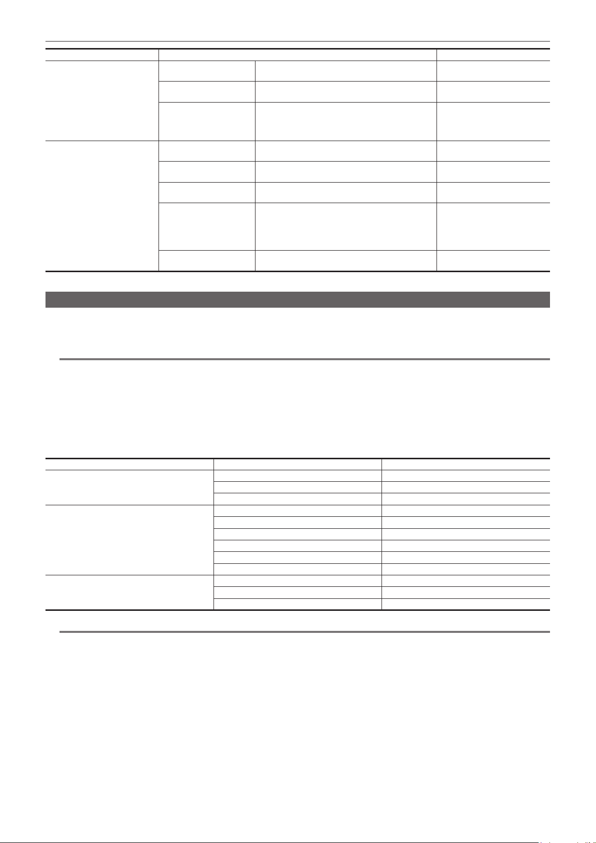
Chapter 3 Preparation — P2 card
P2 card access LED P2 card status Mode check display*
Card full
Write protect
Flashing green slowly
Unrecordable card
Card not supported
Illegal format
No card
Off
Unauthenticated card
USB non-access
* Mode check is displayed in the viewnder. For details, refer to “Screen status display” (page 165).
There is no free space on the P2 card. Reading only is
possible.
The write-protect switch on the P2 card is at the Protect
position. Reading only is possible.
Recording is not possible by the currently set recording
format since the SD memory card, etc. is inserted. To
record the card, change the recording format or use a
P2 card.
This card cannot be used on the camera. Replace the
card.
The P2 card is not properly formatted. Reformat the
card.
The P2 card is not inserted. The card is waiting to be
recognized.
This microP2 memory card cannot be authenticated.
Select the main menu → [CLIP] → [AUTHENTICATE],
and enter the password.
For details, refer to “Manual CPS authentication”
(page 125).
The P2 card cannot be accessed since the mode is the
USB device mode.
[FULL]
[PROTECTED]
[REC IMPOSSIBLE]
[NOT SUPPORTED]
[FORMAT ERROR]
[NO CARD]
[AUTH NG]
No display
P2 card recording time
r P2 cards supported on the camera
Optional P2 memory cards and microP2 memory cards with a capacity of 4 GB to 64 GB can be used with the camera.
NOTE
@@
t AJ-P2C002SG (2 GB) cards cannot be used.
t Following P2 cards cannot be used for recording when AVC-Intra 100 for 1080/59.94P or 1080/50P is selected.
- P2 memory cards of R, A, or E series
t The driver installed on the camera may be required to be updated depending on the type of P2 card. (page 217)
t Refer to our support desk at the following website for the latest information not included in these operating instructions.
http://pro-av.panasonic.net/
r P2 card recording times
(Example when a 64 GB card is used)
System mode Recording format (codec) Recording time
AVC-Intra 100 Approx. 32 min
1080P
1080i, 720P
480i, 576i
AVC-LongG 25 Approx. 128 min
AVC-LongG 12 Approx. 240 min
AVC-Intra 100 Approx. 64 min
AVC-Intra 50 Approx. 128 min
AVC-LongG 50 Approx. 128 min
AVC-LongG 25 Approx. 256 min
AVC-LongG 12 Approx. 480 min
DVCPRO HD Approx. 64 min
DVCPRO50 Approx. 128 min
DVCPRO Approx. 256 min
DV Approx. 256 min
NOTE
@@
t The above table shows values for regular recording. With native recording, even longer recording times are available depending on the system mode.
t In the case of 32 GB P2 cards, the recording time becomes 1/2 of the above recording times, in the case of 16 GB P2 cards, the recording time
becomes 1/4, and in the case of 8 GB P2 cards, the recording time becomes 1/8.
t Indicated capacities include management and other area, so the space available for recording is less than the values in the table above.
– 49 –
Page 50

Chapter 3 Preparation — P2 card
Dividing clips recorded on P2 cards
If P2 cards with a capacity of 8 GB or more are used on the camera, recording is automatically continued as another clip when a single continuous
recording time exceeds the following times. When thumbnails for clips are handled (displayed, deleted, restored, etc.) on P2 devices, they can be
handled as a single clip. Clips may be displayed as separate clips in nonlinear editing software and on a computer.
When recording on microP2 memory cards that exceed 32 GB in AVC-LongG codec, recording can be continued as the same clip by selecting the main
menu → [RECORDING SETUP] → [FILE SPLIT] → [ONE FILE].
A clip will be divided into recording les of approximately 128 seconds each when [SHORT SPLIT] is selected in the main menu → [RECORDING
SETUP] → [FILE SPLIT]. They can be operated as a single clip when the thumbnails of clips are operated on the P2 device.
The dividing unit of the recording les will become smaller when [SHORT SPLIT] is selected while the rec during upload function is used, allowing to
make the timing to start the clip transfer earlier. For details, refer to “Rec during upload function” (page 209).
[SHORT SPLIT] is disabled in interval recording, one-shot recording, and loop recording modes.
Recording format (excluding native recording) Continuous recording time
AVC-Intra 100 (1080P) Approx. 3 min
AVC-Intra 100 (1080i)
DVCPRO HD
AVC-LongG 50
AVC-Intra 50
DVCPRO50
AVC-LongG 25
DVCPRO
DV
AVC-LongG 12 Approx. 40 min
Approx. 5 min
Approx. 10 min
Approx. 20 min
CPS (Content Protection System)
The microP2 memory card supports the security function “Content Protection System” that allows encryption formatting to prevent data leak to third
parties.
To use the CPS function, set a CPS password to the body, and enable the microP2 memory card authentication and encryption formatting functions. An
encrypted microP2 memory card will be automatically recognized between devices where the same CPS password is set, and recording and playback
of the microP2 memory card are enabled. For details, refer to “Setting CPS password” (page 124).
NOTE
@@
t Setting or deleting of CPS can be performed in the main menu → [CLIP] → [PROPERTY] → [CPS PASSWORD].
t Up to 16 characters can be input.
t The encrypted microP2 memory card is not recognized on the SD card slot in a computer.
t If the card is unable to be recognized, authenticate with the correct password or format and use the card as recording media. Recording data on the
card failed to be recognized cannot be checked. Do not perform any operation other than manual authentication and formatting with the failed card
inserted.
t To access the encrypted card from a computer in the USB device mode, authenticate the encrypted card with P2 Viewer Plus.
How to handle data recorded on P2 cards
P2 cards are semiconductor memory cards that are used as the recording medium in the professional video production and broadcasting devices that
make up the DVCPRO P2 series.
f Since data recorded in the P2 format is in a le format, they have excellent compatibility with computers. The le structure is a unique format, which
in addition to video and audio data in MXF les contains various other important information items. The folder structure links data recorded in the P2
format as shown below.
Drive:\
CONTENTS
AVCLIP
AUDIO
CLIP
ICON
PROXY
VIDEO
VOICE
LASTCLIP.TXT*
All these folders are required.
If even part of this information is modified or deleted, the data may no longer
be recognized as P2 data, or the card may no longer be able to be used with
P2 devices.
This is the file to which the information of the final clip that was recorded
with the P2 device is written.
– 50 –
Page 51

Chapter 3 Preparation — P2 card
NOTE
@@
t P2 cards formatted on devices other than microP2 memory card compatible devices do not have the AVCLIP folder. For P2 cards without the AVCLIP
folder, the folder will automatically be created when recording is performed on microP2 memory card compatible devices.
t When transferring data from a P2 card to a computer, or when rewriting data saved on a computer back to a P2 card, to prevent data loss be sure to
download the special “P2 Viewer Plus” software. For details on downloading P2 Viewer Plus and the operating environment, visit the support desk at
the following website:
http://pro-av.panasonic.net/
t Follow the steps below to use general IT tools such as Microsoft Windows Explorer or Apple Finder to transfer the data to a computer. However, be
sure to use P2 Viewer Plus when bringing data back to a P2 card.
- Transfer the corresponding CONTENTS folder and LASTCLIP.TXT le together as a set.
- Do not transfer individual les from the CONTENTS folder.
- When copying, copy the LASTCLIP.TXT le at the same time as the CONTENTS folder.
- When transferring the data in multiple P2 cards to a computer, create a folder for each P2 card to prevent clips with the same name from being
overwritten.
- Do not delete data from the P2 card.
- Be sure to format P2 cards on a P2 device or P2 Viewer Plus.
– 51 –
Page 52

Chapter 3 Preparation — Tally lamp
Tally lamp
The tally lamp will ash when the camera is in the following status.
f When there is no remaining battery (once per second)
f The P2 card has less free space to record and the battery level is low (one time per second)
f The P2 card has been removed while being accessed (four times per second)
f The P2 card has no more space to record (four times per second)
f When warnings such as a system error or recording abnormality are displayed (four times per second)
For details, refer to “Warning system” (page 213).
Back tally lamp
Rear tally lamp
– 52 –
Page 53

Chapter 4 Shooting
This chapter describes the basic procedure for recording. It also describes special shooting methods such as pre-recording and loop recording.
Page 54
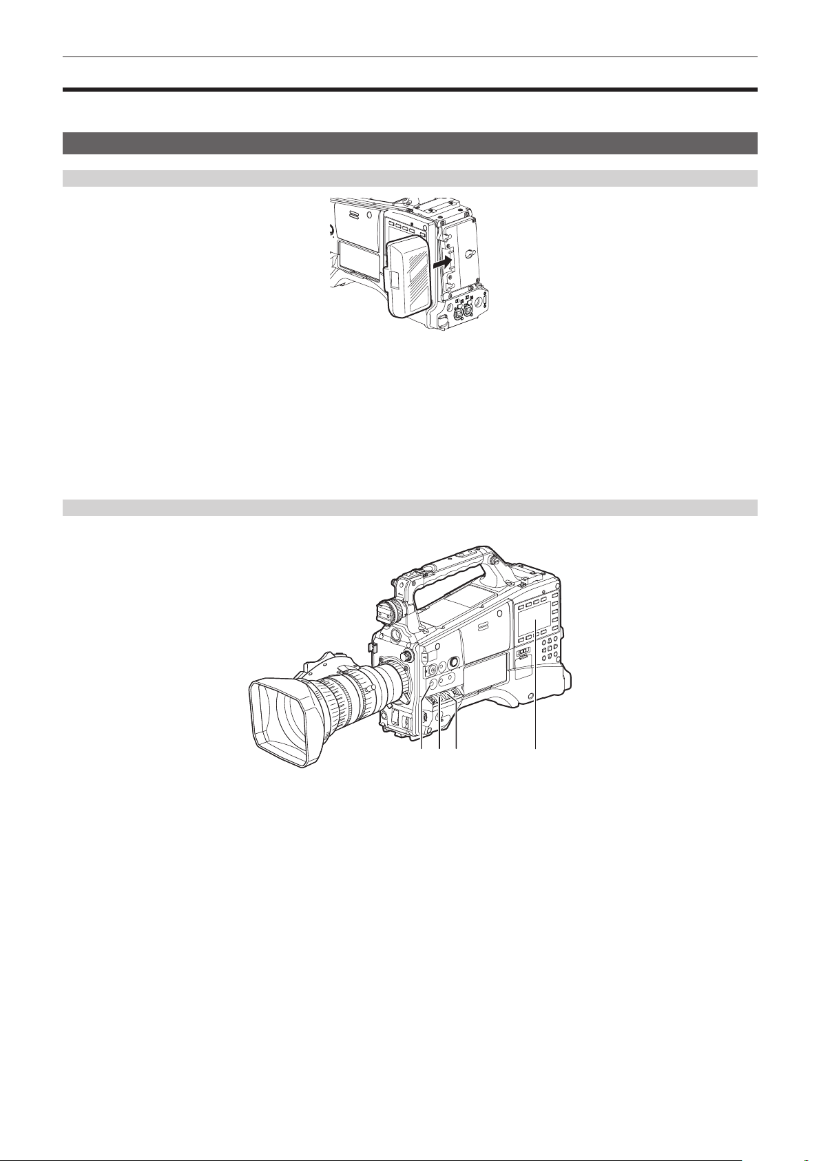
Chapter 4 Shooting — Basic procedures
Basic procedures
This section describes the basic procedures for shooting. Before you actually leave for shooting, pre-inspect your system to ensure that it works properly
after making preparations. (page 44)
Preparation
Power supply setup to P2 card insertion
Fig. 1
Insert a charged battery pack. (Fig. 1)
1
Turn the <POWER> switch <ON>, and check the battery charge level.
2
Check the battery charge level indication on the viewnder or the [HOME] screen of SmartUI.
If the battery charge level shows lower than actual, check the battery settings. (page 150) If the settings are correct, replace with a fully charged
battery.
Insert the P2 card. (page 47)
3
Shooting and recording switch settings
After turning on the power and inserting the P2 card, set the switches as follows before starting operations.
a b dc
a: <USER MAIN> button
The [Y GET] function is assigned in the factory settings.
b: <GAIN> switch
Normally, set this to <L> (0 dB). If conditions are too dark, set the gain to an appropriate value.
c: <OUTPUT>/<AUTO KNEE> selector switch
Set this switch to <CAM>/<ON>.
d: SmartUI
1 On the [SET01:TC/UB] screen, set [TC_MD] to [F-RUN] or [R-RUN].
2 On the [AUD02:INPUT] screen, set [LVL] to [AUTO].
– 54 –
Page 55

Chapter 4 Shooting — Basic procedures
For shooting
White/black balance adjustment to completion of recording
For shooting, use the following steps.
b
a
c db
a: <ND FILTER> dial
b: <REC> button
c: <SHUTTER> switch
d: <AUTO W/B BAL> switch
e: <WHITE BAL> switch
Switch the <ND FILTER> dial setting according to the light conditions.
1
Operate the <WHITE BAL> switch.
2
r When white balance is already saved in memory
f Set the <WHITE BAL> switch to <A> or <B>.
r When neither white or black balance is saved in memory and you have no time to adjust the white balance
f Set the <WHITE BAL> switch to <PRST>.
The value can be changed to 3200 K, 5600 K, or the user-specied variable value by pushing the <AUTO W/B BAL> switch towards the <AWB>
side, and while the color temperature is displayed, pushing the <AUTO W/B BAL> switch towards the <AWB> side again. The variable value can
be set with the jog dial button. (page 62)
r To adjust the white balance on the spot
f Select the lter matched to the lighting conditions. Set the <WHITE BAL> switch to <A> or <B>, shoot a white subject at the center of the screen,
and perform the following steps to adjust the white balance.
1) Push the <AUTO W/B BAL> switch towards the <AWB> side to adjust the white balance. (page 61)
2) Push the <AUTO W/B BAL> switch towards the <ABB> side to adjust the black balance. (page 62)
e
3) Push the <AUTO W/B BAL> switch towards the <AWB> side to adjust the white balance again.
Point the camera at the subject and adjust the focus and zoom.
3
When using the electronic shutter, set the shutter speed/shutter mode. (page 64)
4
Press the <REC> button to start recording.
5
To stop recording, press the <REC> button again.
6
NOTE
@@
t During recording, operation buttons (<%/REW>, <FF/)>, <PLAY/PAUSE>, <STOP>) do not function.
t When highly bright subjects (e.g. sun or lighting) are shot, the periphery of the subject might be colored.
– 55 –
Page 56
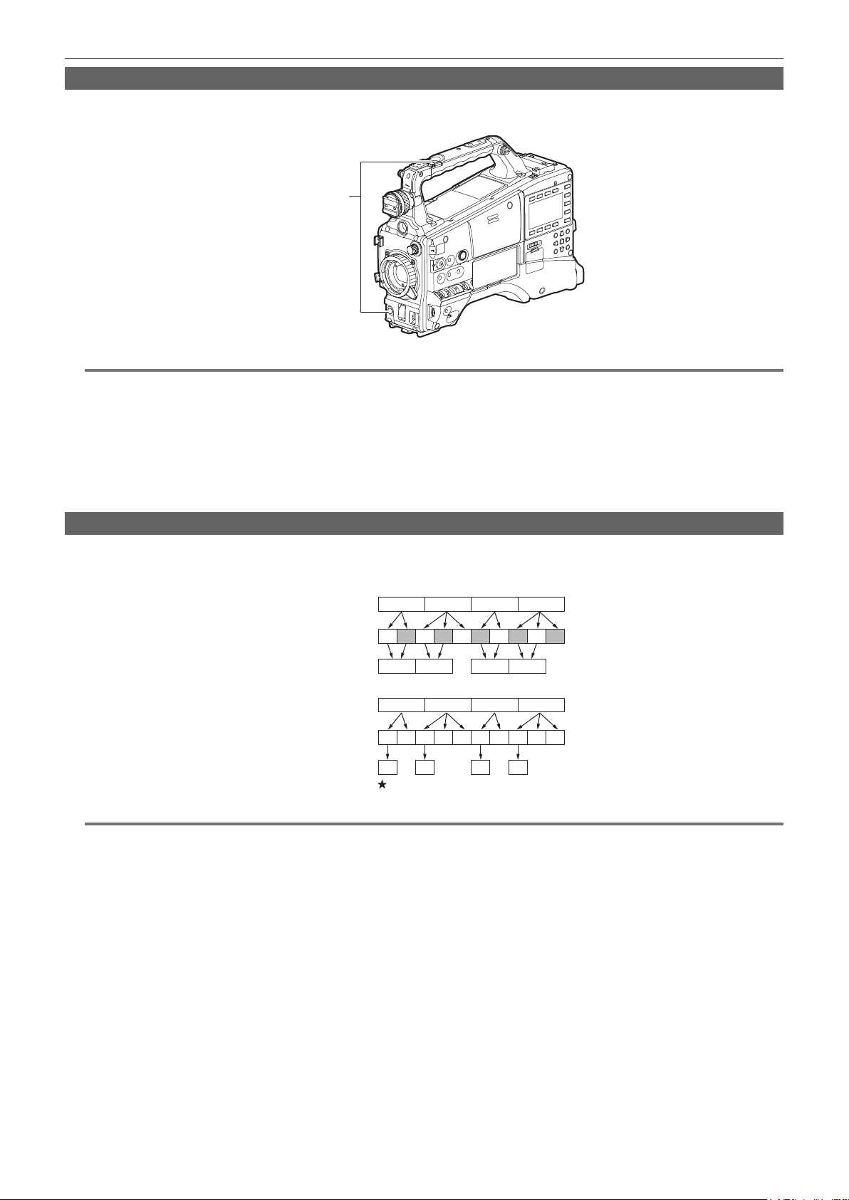
Chapter 4 Shooting — Basic procedures
Standard recording
Press the <REC> button to start recording of video and audio on the P2 card.
Data consisting of video and audio (including additional information) generated by a single shooting action is called a “clip”.
<REC> button
NOTE
@@
t In the following cases, it may take time to complete writing to the P2 card.
- Stopping of short-term recording
- When stopping recording immediately after recording is performed on the second P2 card
t If recording is not stopped even when the <REC> button is pressed, [REC PAUSE INVALID] is displayed at the center of the screen. Once stopping of
recording becomes possible, the message disappears.
t Also immediately after inserting a P2 card or turning on the power, recording is started using the internal memory of the camera. In this case, recording
cannot be stopped until the P2 card has been recognized.
Push the <DISP/MODE CHK> switch towards the <CHK> side and check the P2 card status on the [SLOT1], [SLOT2], and [SLOT3] rows displayed in
the viewnder.
Native recording
This recording method extracts and records valid frames at the shooting frame rates in 1080P recording and AVC-Intra recording in 720P.
With native recording, you can record longer than the normal recording time.
Even in native recording, the rate for outputting camera images and playback images is 59.94 frames or 50 frames that are pulled down.
Camera shooting
(1080/24PN)
2:3 pull-down
Recording
Camera shooting
(720/24PN)
2:3 pull-down
Recording
NOTE
@@
t Recording starts from the beginning of a 4-frame cycle for 24PN (native recording) and 2-frame cycle for 30PN of 720P (native recording). Therefore,
the time code may become non-continuous when clips are recorded continuously in system modes with different recording cycles.
t Also immediately after inserting a P2 card or turning on the power, recording is started using the internal memory of the camera. In this case, recording
cannot be stopped until the P2 card has been recognized.
Push the <DISP/MODE CHK> switch towards the <CHK> side and check the P2 card status on the [SLOT1], [SLOT2], and [SLOT3] rows displayed in
the viewnder.
A
Ao
Ae Bo Be Bo Ce Co De Do De
A B
A
A B B B C C D
A
A B C D
Valid frames
B C D
C D
B C D
D D
– 56 –
Page 57

Chapter 4 Shooting — Basic procedures
Selecting the resolution, codec, and video format for recording
The resolution of the recording image (1080P, 1080i, 720P, 480i, 576i) and recording codec (AVC-Intra, AVC-LongG, DVCPRO HD, etc.) and recording
frame rate can be selected.
Set in the main menu → [SYSTEM MODE] → [LINE&FREQ] and [REC FORMAT].
r Resolution: 1920×1080
[LINE&FREQ] [REC FORMAT] [CAMERA MODE]
[1080-59.94P] [AVC-I100/60P]
[AVC-G25/60P]
[AVC-G12/60P]
[AVC-I100/30PN]
[AVC-G50/30PN]
[AVC-G25/30PN]
[AVC-G12/30PN]
[AVC-I100/24PN]
[AVC-G50/24PN]
[AVC-G25/24PN]
[AVC-G12/24PN]
[1080-59.94i] [AVC-I100/60i]
[AVC-I50/60i]
[AVC-G50/60i]
[AVC-G25/60i]
[AVC-G12/60i]
[DVCPRO HD/60i]
[1080-50P] [AVC-I100/50P]
[AVC-G25/50P]
[AVC-G12/50P]
[AVC-I100/25PN]
[AVC-G50/25PN]
[AVC-G25/25PN]
[AVC-G12/25PN]
[1080-50i] [AVC-I100/50i]
[AVC-I50/50i]
[AVC-G50/50i]
[AVC-G25/50i]
[AVC-G12/50i]
[DVCPRO HD/50i]
[1080-23.98PsF] [AVC-I100/24PN]
[AVC-G50/24PN]
[AVC-G25/24PN]
[AVC-G12/24PN]
Setting
Recording format
— 1080/60P
1080/30PN Native
1080/24PN Native
— 1080/60i
— 1080/50P
1080/25PN Native
— 1080/50i
— 1080/24PN Native
r Resolution: 1280×720
[LINE&FREQ] [REC FORMAT] [CAMERA MODE]
[720-60P] [AVC-I100/60P]
[AVC-I50/60P]
[AVC-G50/60P]
[AVC-G25/60P]
[AVC-G12/60P]
[DVCPRO HD/60P]
[AVC-I100/30PN] 720/30PN Native
[AVC-I100/24PN] 720/24PN Native
[720-50P] [AVC-I100/50P]
[AVC-I50/50P]
[AVC-G50/50P]
[AVC-G25/50P]
[AVC-G12/50P]
[DVCPRO HD/50P]
[AVC-I100/25PN] 720/25PN Native
r Resolution: 720×480
[LINE&FREQ] [REC FORMAT] [CAMERA MODE]
[480-59.94i] [DVCPRO50/60i]
[DVCPRO/60i]
[DV/60i]
Setting
Setting
Recording format
— 720/60P
— 720/50P
Recording format
[60i] 480/60i
[30P] 480/30P over 60i 2:2 Pull Down
– 57 –
Page 58

r Resolution: 720×576
Chapter 4 Shooting — Basic procedures
Setting
[LINE&FREQ] [REC FORMAT] [CAMERA MODE]
[576-50i] [DVCPRO50/50i]
NOTE
@@
t In 480i/576i mode, the video aspect ratio for recording and output can be changed.
[DVCPRO/50i]
[DV/50i]
[50i] 576/50i
[25P] 576/25P over 50i 2:2 Pull Down
Recording format
– 58 –
Page 59

Chapter 4 Shooting — Adjustable settings when shooting
Adjustable settings when shooting
Congure the settings as necessary before you start shooting.
Focus assist function
The focus assist function enables you to focus the target easily.
Expanded display, focus assist color display (in which the contours of the image are displayed in the selected color), and focus bar display are available
in the viewnder.
Expanded display [EXPAND]
Set to [EXPAND] in the main menu → [SW MODE] → [FOCUS ASSIST MODE] beforehand.
When the <FOCUS ASSIST> button is pressed, the center of the screen is expanded approx. three times so that you can focus the image easily.
EXPANDED
f In the expanded display, the status display and zebra pattern disappear, and [EXPANDED] is displayed at the top of the screen.
f The method to cancel the expanded display can be selected in the main menu → [SW MODE] → [EXPAND MODE].
- [10SEC]: Cancels in 10 seconds.
- [HOLD]: Does not cancel until the <FOCUS ASSIST> button is pressed again.
- [UNTIL REC]: Cancels when recording starts. Expanded display is not available during recording.
NOTE
@@
t The viewnder screen is expanded.
t Expanded display is unavailable in the video output, SDI output, and HDMI output.
Focus assist color display [FOCUS IN COLOR]
Set the main menu → [SW MODE] → [FOCUS ASSIST MODE] to [FOCUS IN COLOR] in advance.
Select one of [RED]/[GREEN]/[BLUE] in the main menu → [SW MODE] → [FOCUS IN COLOR SETTING] → [PEAKING COLOR].
The contour of the image is bordered with the selected color when the <FOCUS ASSIST> button is pressed. At this time, the screen frame will be in the
selected color.
Adjust the focus so that the contour of the subject to focus will turn into the selected color.
NOTE
@@
t When various status information is displayed, they will disappear.
t Only displayed on the viewnder.
t When the main menu → [SW MODE] → [FOCUS IN COLOR SETTING] → [PICTURE B/W] is set to [ON], the image will turn to black and white when
the <FOCUS ASSIST> button is pressed.
Focus bar display [FOCUS BAR]
The focus bar can be displayed when [ON] is set in the main menu → [DISPLAY SETUP] → [FOCUS BAR].
The degree of focus is indicated by the length of the bar.
f White bar: Focus bar display
f Green line: Peak display
Not in focus The bar extends to the right when the viewfinder is
in-focus.
– 59 –
Page 60

Chapter 4 Shooting — Adjustable settings when shooting
Level gauge function
A level gauge that indicates the horizontal and vertical inclinations of the camera recorder can be displayed in the viewnder.
Horizontal direction
Example) When correcting the inclination towards the left
Vertical direction
Example) When correcting the downward inclination
Orange lines will be displayed when inclined. Orange lines will be changed to green lines when there is almost no inclination. Inclinations will be
displayed up to approximately ±45° in the horizontal direction, and up to ±30° in the vertical direction.
Select [ON] in the main menu → [DISPLAY SETUP] → [LEVEL GAUGE].
1
NOTE
@@
t The level gauge display is not recorded.
t While moving the camera, the level gauge may not be displayed properly.
t When shooting while tilting the camera upward or downward greatly, the level gauge may not be displayed properly.
t When pressing the USER button where [LEVEL GAUGE] is assigned in the main menu → [USER SW], [ON] and [OFF] can be switched.
t When holding down the USER button where [LEVEL GAUGE RESET] is assigned in the main menu → [USER SW], the setting will be reset to the
factory setting.
t When pressing the USER button where [LEVEL GAUGE RESET] is assigned in the main menu → [USER SW].
– 60 –
Page 61

Chapter 4 Shooting — Adjusting the white and black balance
Adjusting the white and black balance
To obtain high-quality video at all times using the camera, the white and black balance must be adjusted according to conditions.
To obtain higher image quality, adjust in the order of AWB (white balance adjustment) → ABB (black balance adjustment) → AWB (white balance
adjustment).
NOTE
@@
t When white or black balance is adjusted while video is disrupted by the generator lock, adjustment may not be performed correctly. Adjust white or
black balance again after video has returned to normal.
Adjusting the white balance
The white balance must be adjusted again when the lighting conditions change. Follow the steps below to adjust the white balance automatically.
r When storing in <A> of the <WHITE BAL> switch
Set the <GAIN> switch.
1
Normally, set this to 0 dB. If it is too dark, set the gain to an appropriate value.
Set the <WHITE BAL> switch to <A>.
2
Switch the <ND FILTER> dial setting according to the light conditions.
3
Place the white pattern at a point where the light conditions match those for the light source for the subject, and zoom in on the
4
white pattern so that the white color appears in the screen.
Adjust the lens aperture.
5
Adjust the iris so that the brightness of Y GET is approx. 70%.
Push the <AUTO W/B BAL> switch towards the <AWB> side.
6
White balance is automatically adjusted.
r White pattern
f A white object (cloth or wall) near the subject may also be used for the white pattern.
f Required size of white pattern is as follows.
1/3 or more of the screen width
1/3 or more of the screen height
f Keep bright spotlights out of the screen.
f The white pattern must be placed at the center of the screen.
r Message displayed in the viewnder
Status Message Remark
During adjustment [AWB Ach ACTIVE]
Adjustment completed [AWB A OK 3200K]
When the color temperature of the subject is lower
than 2000 K or higher than 15000 K
r [COLOR TEMP Ach SETTING]/[COLOR TEMP Bch SETTING] setting
f The color hue can be changed after the white balance has been adjusted automatically, after setting each item in the main menu → [SCENE FILE] →
[COLOR TEMP Ach SETTING]/[COLOR TEMP Bch SETTING].
f Adjusting either one of [COLOR TEMP], [R Gain], [B Gain], and [G AXIS] changes the other three values.
f Applying white balance automatic adjustment again resets [COLOR TEMP], [R Gain], [B Gain], and [G AXIS].
[AWB NG COLOR TEMP LOW]
[AWB NG COLOR TEMP HIGH]
f The adjusted value is automatically stored in the
specied memory (A or B).
f [AWB NG COLOR TEMP LOW] indicates that
the temperature is lower than the displayed
temperature. [AWB NG COLOR TEMP HIGH]
indicates that the temperature is higher than the
displayed temperature.
– 61 –
Page 62

Chapter 4 Shooting — Adjusting the white and black balance
When you have no time to adjust the white balance
f Set the <WHITE BAL> switch to <PRST>.
The value can be changed to 3200 K, 5600 K, or the user-specied variable value by pushing the <AUTO W/B BAL> switch towards the <AWB>
side, and while the color temperature is displayed, pushing the <AUTO W/B BAL> switch towards the <AWB> side again. The variable value can be
changed with the jog dial button while the color temperature indication [V****K] at the bottom of the screen is highlighted. At this time, if the jog dial
button is turned while pressing, the setting value can be changed faster. Highlight disappears in several seconds if the setting is not changed.
When the white balance has not been automatically adjusted
f When the auto tracking white balance (ATW) function is operating, white balance cannot be adjusted.
f When the white balance has not been successfully adjusted, the viewnder displays an error message.
Error message Meaning Remedy
[AWB Ach NG] or [AWB Bch NG] The color temperature is too high, or too low. Select the appropriate lter.
[LOW LIGHT] There is insufcient light. Increase the amount of light or increase gain.
[LEVEL OVER] There is too much light. Decrease the amount of light or decrease gain.
[COLOR TEMP LOW] or [COLOR TEMP HIGH] The color temperature is too high, or too low. Select the appropriate lter or light source.
Manual setting of color temperature
The color temperature of white balance can be adjusted by the setting menu.
Set the color temperature in the main menu → [SW MODE] → [W.BAL VAR].
1
This can be set from [2000K] to [15000K].
Viewnder display for white balance
For details, refer to “Screen status display” (page 165).
Setting the auto tracking white balance (ATW) function
The camera is equipped with the Auto Tracking White Balance (ATW) function that automatically tracks the white balance of images according to the
lighting conditions.
The auto tracking white balance function can be assigned to <B> of the <WHITE BAL> switch. Congure the settings in the main menu → [SW MODE]
→ [ATW].
Note that if the auto tracking white balance function is assigned to the USER button, the function follows the operation of the USER button.
For details, refer to “Assigning functions to USER buttons” (page 67).
Canceling the auto tracking white balance
Press the USER button to which auto tracking white balance function is assigned again or change the position of the <WHITE BAL> switch. Note that if
the auto tracking white balance function is set to the <WHITE BAL> switch, the function cannot be canceled with the USER button.
NOTE
@@
t This function does not guarantee 100% accuracy for the white balance. Note that the tracking performance relative to changes in ambient lighting and
white balance performance has been given a certain degree of latitude.
Adjusting the black balance
Black balance must be adjusted in the following instances:
f When the camera is used for the rst time
f When the camera has not been used for a long time
f When the ambient temperature has changed considerably
f When super gain is set with the USER button
f When changing the gain switch values
f When switching the items in the main menu → [SYSTEM MODE] → [REC FORMAT]
To shoot optimum video, we recommend adjusting the black balance immediately before shooting.
Before adjusting the black balance, prepare the conditions for adjusting the white balance.
Set the <WHITE BAL> switch to <A> or <B>.
1
Push the <AUTO W/B BAL> switch towards <ABB> and then release it.
2
The <AUTO W/B BAL> switch returns to the central position and the black balance is automatically adjusted.
– 62 –
Page 63

Chapter 4 Shooting — Adjusting the white and black balance
r Message displayed in the viewnder
Status Message Remark
During adjustment [ABB ACTIVE]
Adjustment completed [ABB OK]
NOTE
@@
t During black balance adjustment, the aperture is set to automatically shut out light.
t During recording, black balance cannot be adjusted.
t During the automatic black balance execution, recording to the P2 card is not performed by pressing the <REC> button.
t The gain switching circuit is automatically switched during black balance adjustment. Flicker or noise sometimes appears on the viewnder screen.
This is not a malfunction.
f The adjusted value is automatically stored in
memory.
Black balance memory
Values stored to memory are saved even if the camera is turned off.
– 63 –
Page 64

Chapter 4 Shooting — Setting the electronic shutter
Setting the electronic shutter
Setting the shutter mode and speed
Switch the <SHUTTER> switch to set the shutter speed in the shutter mode.
<SHUTTER> switch
Press the <SHUTTER> switch positioned at <OFF> towards the <ON> side.
1
Press the <SHUTTER> switch from <ON> towards the <SEL> side, and repeat this operation until the desired mode or speed is
2
displayed on the viewfinder.
f If all modes and speeds are available, the display changes in the following order.
r In the case of 60i, 60P recording
1/15 1/30 1/60 1/100 1/250S/S 1/120
r In the case of 50i, 50P recording
1/12.5 1/25 1/60 1/250S/S 1/120
r In the case of 30P recording
1/15 1/30 1/50 1/120S/S
r In the case of 25P recording
1/12.5 1/25 1/50 1/120S/S
r In the case of 24P recording
1/12 1/24 1/50 1/120S/S
f [S/S] display is indicated in the synchro scan mode.
NOTE
@@
t Whichever mode the electronic shutter is used in, the higher the shutter speed, the lower the sensitivity of the camera becomes.
t When the aperture is in the automatic mode, it will increasingly open and the depth of focus will become shallower as the shutter speed is increased.
t The screen might be disrupted when the synchro scan and shutter settings are changed.
t Under lighting conditions using uorescent lighting or other discharge tube, horizontal stripes might appear on screen. If this happens, this can be
improved by adjusting the shutter speed.
t A subject that quickly crosses the camera may appear distorted when shot. This is due to the method applied for reading the signals from the pickup
device (MOS sensor), and is not a malfunction.
t Red, blue, or green spots might appear on screen at slow shutter speeds, though this is not a malfunction.
1/50
1/60
1/60
1/60
1/500 1/1000 1/2000
1/500 1/1000 1/2000
1/250 1/500 1/1000
1/250 1/500 1/1000
1/250 1/500 1/1000
Viewnder display for shutter
For details, refer to “Screen status display” (page 165).
– 64 –
Page 65

Chapter 4 Shooting — Setting the electronic shutter
Setting the synchro scan mode
Perform the following steps to operate.
Jog dial button
<SHUTTER> switch
Press the <SHUTTER> switch from <ON> towards the <SEL> side to set the camera to synchro scan mode [S/S].
1
Change the setting value of the synchro scan shutter.
2
The setting value can be changed with the jog dial button while the synchro shutter indication displayed at the bottom of the screen is highlighted. At
this time, if the jog dial button is turned while pressing, the setting value of the shutter speed can be changed faster. Highlight disappears in several
seconds if the setting is not changed.
The shutter speed display in the synchro scan mode can be switched between seconds and angle in the main menu → [SCENE FILE] → [SYNC
SCAN TYPE].
Variable ranges in each mode
Mode Variable range
60P/60i 1/60.0 – 1/249.8
50P/50i 1/50.0 – 1/250.0
25P/25PN 1/25.0 – 1/250.0
30P/30PN 1/30.0 – 1/249.8
24PN 1/24.0 – 1/249.8
When [deg] is selected in the main menu → [SCENE FILE] → [SYNC SCAN
TYPE]
f After the setting has been changed in the main menu → [SYSTEM MODE], the shutter speed may have been changed.
f If you set [deg] in the main menu → [SCENE FILE] → [SYNC SCAN TYPE], setting and display can be performed as in the shutter open angle.
3.0d – 360.0d
– 65 –
Page 66

Chapter 4 Shooting — Flash band compensation (FBC) function
1
599
min
2199minNECSE1
.
V
FBCDR
S
Flash band compensation (FBC) function
The camera is equipped with a function for compensating and reducing band-like interference (called “ash band”) that occurs due to the MOS pickup
device when shooting in environments where ash strobe light such as that from still cameras is present.
Change over time
Flash firing
Shot image
(FBC OFF)
Setting the ash band compensation function
Assign the ash band compensation function to the USER buttons (<USER MAIN>/<USER1>/<USER2>).
By pressing the USER button that is assigned with the ash band compensation function, the function turns on, and ash strobe from a still camera, etc.
can be detected and compensated.
For details, refer to “Assigning functions to USER buttons” (page 67).
Flash band
<USER MAIN>/<USER1>/<USER2> buttons
When the ash band compensation function is enabled, [FBC] is displayed on the status screen.
* Not displayed when [OFF] is set in the main menu → [DISPLAY SETUP] → [DISPLAY SETTING] → [FBC].
NOTE
@@
t When the ash strobe lights, the following phenomena may occur. These are due to the ash band compensation function and are not malfunctions.
- Moving subjects look as if they have been stopped for a moment.
- The resolution drops when the ash strobe lights.
- Horizontal lines appear in the video when the ash strobe lights.
- Flash bands appear only in images shot at the time the ash strobe lights.
Using the ash band compensation function
The ash band compensation function is activated when there are large changes in brightness at the bottom of the screen regardless of whether there
is ash strobe light. The ash band compensation function may be activated depending on the shooting environment such as where a bright window has
zoomed in and then out. So, we recommend use of this function in shooting environments where ash strobe lighting is anticipated.
Even if ash strobe lighting occurs, sufcient ash band compensation function effect may not be obtained in some shooting environments.
Flash band compensation function operation conditions
f The ash band compensation function can be used when all of the following conditions are satised.
- Either in 59.94i, 59.94P, 50i, or 50P mode
- Scan reverse and digital zoom functions are not operating
- <SHUTTER> switch is <OFF>
f Even if the ash band compensation function is enabled, the ash band compensation function is forcibly disabled if the camera is changed to a mode
where the ash band compensation function cannot be used.
To use the function again, return to a mode where the function can be used, and press the USER button to turn on the ash band compensation
function.
The ash band compensation function is disabled once the power is turned off.
f Even if the ash band compensation function is active, the ash band compensation function temporarily turns off when the <SHUTTER> switch is
turned <ON>. The ash band compensation function turns on again by turning the <SHUTTER> switch <OFF>.
– 66 –
Page 67

Chapter 4 Shooting — Assigning functions to USER buttons
Assigning functions to USER buttons
Selected functions can be assigned to the <USER MAIN>, <USER1>, <USER2>, and lens <RET> buttons.
Set each function to be assigned in the main menu → [USER SW], [USER MAIN], [USER1], [USER2], [RET SW].
In the factory settings, [Y GET] is assigned to the <USER MAIN> button, [TEXT MEMO] to the <USER1> button, [LEVEL GAUGE] to the <USER2>
button, and [REC CHECK] to the <RET> button of the lens.
<USER MAIN>/<USER1>/<USER2> buttons
Selectable functions
The functions that can be assigned to the USER button are as follows:
Item Description
[INHIBIT] Disables assignment of functions.
[LEVEL GAUGE] Assigns the function for switching the level gauge display function to enabled/disabled.
[LEVEL GAUGE
RESET]
[WFM]
[D.ZOOM x2]
[D.ZOOM x4]
[DRS] Assigns the function for switching the dynamic range stretcher function to enabled/disabled.
[FBC] Assigns the function for switching the ash band compensation function to enabled/disabled.
[S.GAIN] Assigns the function for switching the super gain function to enabled/disabled.
[ATW] Assigns the function for switching the auto tracking white balance function to enabled/disabled.
[ATW LOCK]
[SPOTLIGHT] Assigns the function for switching the auto iris control function for the spotlight to enabled/disabled.
[BACKLIGHT] Assigns the function for switching the auto iris control for the backlight compensation to enabled/disabled.
[Y GET] Assigns the function for displaying the brightness level of the frame area displayed near the center.
[PRE REC] Assigns the function for switching the pre-recording function to enabled/disabled.
[TEXT MEMO] Assigns the text memo function.
[SHOT MARK] Assigns the shot mark function.
[DEL LAST CLIP] Assigns the function to delete the clip shot immediately beforehand.
[SLOT SEL] Assigns the function for switching the card to record when multiple cards are inserted in the microP2 memory card slot.
[REC MEDIA]
[AUDIO MON SEL]
[REC CHECK] Assigns the recording check function.
[CAM RET] Return video function is enabled. The signal supplied to the <SDI OUT2/IN> terminal is displayed on the viewnder while the switch is
[BS CALL] The <TALLY/CALL> lamp in AG-BS300P/AG-BS300E is illuminated while the switch is pressed. This is assigned when the AG-BS300P/
[TALK] By pressing the button to enable, the INCOM headset microphone is enabled and talking to the AG-BS300 side becomes possible.
[USB MODE] Assigns the function for switching the USB device mode or USB host mode to enabled/disabled.
[PLAYLIST] Assigns the function for switching the playlist edit mode to transfer/end.
[REC DURING
UPLOAD]
[UPLOAD LIST] Assigns the function to display the upload list of the rec during upload function. To close the upload list, press the <EXIT> button.
[STREAMING
START]
[EVF COLOR] Assigns the function for switching whether to display the viewnder image in color or in black and white.
[LOAD USER FILE] Assigns the function to display the selection screen for the user le saved on the SD memory card. This does not function in the thumbnail
Assigns the function to set the level gauge using the current horizontal and vertical directions as reference values. Holding down the
assigned button will reset to the factory setting.
Assigns the function for switching the waveform display of the waveform monitor. Select the waveform display from the main menu →
[SW MODE] → [WFM MODE].
Assigns the digital zoom function.
Zooms in on the eld angle by 2x/4x vertically and horizontally.
Fixes the white balance value when pressing this item while the auto tracking white balance function is activated. Resumes the auto
tracking white balance function when pressing again.
Assigns the function to select the recording target slot between the P2 memory card slot and microP2 memory card slot. This setting is
linked to the setting value in the main menu → [RECORDING SETUP] → [REC MEDIA].
Assigns the function for switching the output audio channel. If audio channel 1/2 is selected, every press of the assigned button switches
the channel between audio channel 1 monaural, audio channel 1 and 2 stereo, and audio channel 2 monaural. If audio channel 3/4 is
selected, every press of the assigned button switches the channel between audio channel 3 monaural, audio channel 3 and 4 stereo, and
audio channel 4 monaural.
pressed. Use by setting the main menu → [IN/OUT SEL] → [SDI OUT2/IN SEL] to [SDI IN].
AG-BS300E is connected directly and used as an extension system.
Assigns the function for enabling/disabling the rec during upload function.
This setting is linked to the setting value in the main menu → [NETWORK SETUP] → [FTP CLIENT SERVICE] → [REC DURING
UPLOAD].
Assigns the function for starting/stopping streaming from the camera.
This setting is linked to the setting value in the main menu → [NETWORK SETUP] → [STREAMING SETTING] → [START].
screen.
– 67 –
Page 68

Chapter 4 Shooting — Assigning functions to USER buttons
NOTE
@@
t The following functions are also turned off when the camera is turned off.
[WFM]/[D.ZOOM x2]/[D.ZOOM x4]/[DRS]/[FBC]/[S.GAIN]/[ATW]/[ATW LOCK]/[SPOTLIGHT]/[BACKLIGHT]/[Y GET]/[USB MODE]/[PLAYLIST]
t Select the [BS CALL]/[TALK] functions when connecting the camera directly to AG-BS300.
– 68 –
Page 69

Chapter 4 Shooting — Selecting audio input and adjusting recording levels
Selecting audio input and adjusting recording levels
The camera supports independent 4-channel sound recording in all recording formats (HD, SD).
When [LVL] is set to [AUTO] on the [AUD02:INPUT] screen of SmartUI, the recording level of audio channels 1/2/3/4 is automatically adjusted. Also, you
can adjust the level manually by setting it to [MANU].
Selecting audio input signals
Select the input signal to be recorded to audio channels 1/2/3/4 using the [IN] setting on the [AUD02:INPUT] screen of SmartUI. (page 159)
AUD02:INPUT
CH1
[
CH2
CH3/4
]
FRONT
W.L. W.L.
REAR
IN
MANU
] [
[
Set the switch settings and input line in the [AUD02:INPUT] screen of SmartUI. (page 160)
NOTE
@@
t The audio signals recorded in 4-channel are output with SDI signals.
Set audio-related details in the main menu → [AUDIO SETUP]. (page 143)
AUTO
LVL
FRONT
REAR
] [
IN
] [
AUTO
MANU
LVL
]
Adjusting the recording level
Adjust the recording level to audio channels 1/2 by the following procedure. Audio channels 3/4 can be set in the same manner.
Press the <MONITOR SEL> button on the [HOME] screen of SmartUI so that the audio channel level meter displays CH1 and CH2,
1
and make sure that the display is 1 and 2.
Set [LVL] on the [AUD02:INPUT] screen of SmartUI to [MANU].
2
Adjust the level by [+] or [−] on the [AUD01:LEVEL] screen of SmartUI while viewing the audio channel level meter display.
3
When the topmost bar (0 dB) is exceeded, of the [OVER] display is illuminated to indicate that input audio is excessive. Adjust the maximum
level so that the display does not reach 0 dB.
AUD01:LEVEL
CH1
[
CH2
RST][CH3/4
]
A
100
] [
[
–
When you operate the camera alone while recording, use the <F.AUDIO LEVEL> dial to adjust the audio level.
Select the audio channel to be adjusted in advance, and while viewing the level meter of the viewnder, adjust the level by the <F.AUDIO LEVEL>
dial so that input does not become excessive.
+
] [
–
70
] [
+
]
Selecting the <F.AUDIO LEVEL> dial function
Adjust the audio level so that the input does not reach an excess while viewing the level meter on the viewnder.
f Select the audio channel you want to adjust beforehand in the main menu → [AUDIO SETUP] → [RECORDING CH SETTING] → [FRONT VR CH1]
to [FRONT VR CH4].
f Adjust with the <F.AUDIO LEVEL> dial.
f The audio level when the <F.AUDIO LEVEL> dial is at level 10 becomes the value set in the [AUD01:LEVEL] screen of SmartUI.
– 69 –
Page 70

Chapter 4 Shooting — Adjusting image quality
Adjusting image quality
The image quality of the video to be recorded can be set in the main menu → [SCENE FILE]. To change “Advanced settings”, measuring equipment
such as vector scope is necessary.
Detail function
This function thickens or weakens the outlines of images. It effectively softens or sharpens images, but in some cases, the whole image may become
rough due to emphasized noise and edges. To avoid such problems, it is necessary not to add this effect on parts where emphasizing is not needed and
keep the details of the parts.
r General settings
[MASTER DTL]: Sets the level of the detail effect of the whole part.
[DTL CORING]: Sets the level of signal (including noise) not to activate the detail effect.
r Advanced settings
Set in the main menu → [SCENE FILE] → [DETAIL SETTING].
[DETAIL]: Sets [ON]/[OFF] of the detail function.
[V.DTL LEVEL]: Sets the intensity of the detail level in the vertical direction.
[H.DTL FREQ.]: Sets the thickness of the detail level in the horizontal direction.
[V. DTL FREQ.]: Sets the thickness of the detail level in the vertical direction.
[LEVEL DEPEND.]: When the detail of luminosity signal is emphasized, details in the darker parts are compressed. Details of bright areas are also
compressed more when the value set for [LEVEL DEPEND.] is larger.
[KNEE APE LVL]: Sets the detail level of high luminosity areas (high-brightness areas). For operation, 0 is displayed as [OFF].
[DTL GAIN(+)]: Sets the detail level of + direction (to make brighter).
[DTL GAIN(−)]: Sets the detail level of − direction (to make darker).
Skin tone function
This function makes human skin look smoother in images.
R-Y
255
R
[I WIDTH]
[I CENTER]
[Q WIDTH]
[Q PHASE]
Yl
255
0
G
r General settings
[SKIN TONE DTL A]/[SKIN TONE DTL B]/[SKIN TONE DTL C]: Selects what kind of skin color where the skin tone detail function should work from
the three data [SKIN TONE DTL A]/[SKIN TONE DTL B]/[SKIN TONE DTL C]. [SKIN TONE DTL A]/[SKIN TONE DTL B]/[SKIN TONE DTL C] can be set
alone or in combination.
[SKIN TONE ZEBRA]: When [SKIN TONE DTL A]/[SKIN TONE DTL B]/[SKIN TONE DTL C] are enabled, displays the zebra pattern in the selected skin
color eld. The zebra pattern displays the area selected in [SKIN TONE DTL SETTING].
Mg
Q axis
B-Y/0°
B
Cy
I axis
Fig. 1
r Advanced settings
Congure the settings in the main menu → [SCENE FILE] → [SKIN TONE DTL SETTING].
[DETECT TABLE]: Selects the skin color table of the object on which the skin tone table is applied.
[SKIN TONE GET]: Acquires the color information of [A], [B], or [C] selected in [DETECT TABLE] from the area around the center marker. By executing
this menu, [I CENTER] to [Q PHASE] data are acquired automatically.
[SKIN DTL EFFECT]: Sets the effect level of the skin tone detail.
f The color composition of video signal (R/G/B) can be converted to color difference signal (R-Y/B-Y) as in (Fig. 1). Within those ranges, set the area on
which the following skin tone is applied, using the axis across red and cyan (I axis) and the axis across green and magenta (Q axis).
[I CENTER]: Sets the center position on the I axis (the area where the skin tone applied).
[I WIDTH]: Sets the area width where the skin tone is applied, along the I axis with [I CENTER] in the center.
[Q WIDTH]: Sets the area width where the skin tone is applied, along the Q axis with [I CENTER] in the center.
[Q PHASE]: Sets the phase where the skin tone is applied, with the Q axis being the reference.
– 70 –
Page 71
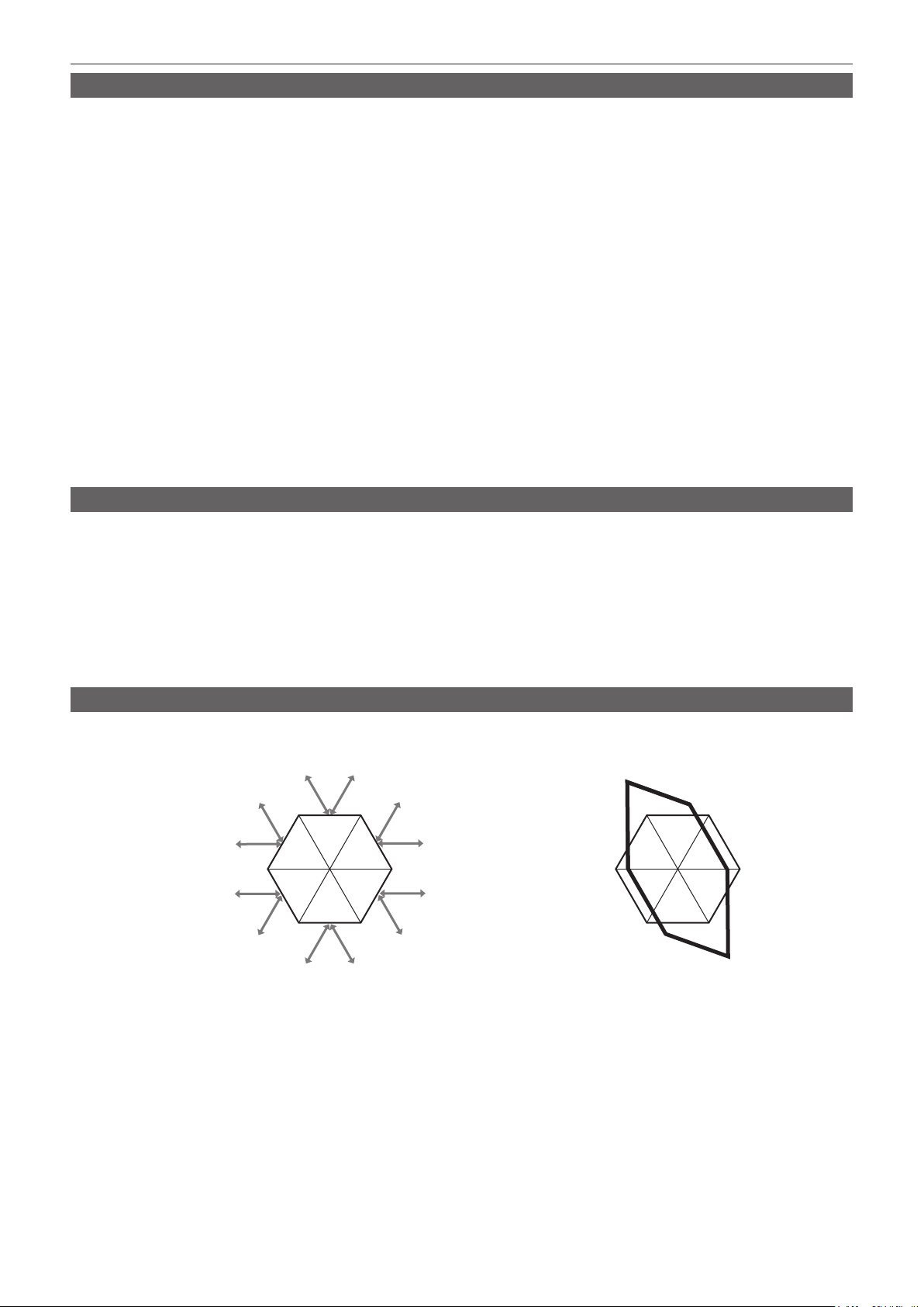
Chapter 4 Shooting — Adjusting image quality
RB gain control function
This function makes settings to add or reduce intensity of red and blue colors according to the position of the <WHITE BAL> switch.
The function works when the switch is at the <PRST> position or when automatic white balance is active. It does not work when auto tracking white
balance is activated.
r General settings
Use the camera with the factory settings.
r Advanced settings
Congure the settings in the main menu → [SCENE FILE] → [RB GAIN CONTROL SETTING].
f When the <WHITE BAL> switch is at <PRST> position
[R GAIN AWB PRE]: Makes settings to add or reduce intensity of red color.
[B GAIN AWB PRE]: Makes settings to add or reduce intensity of blue color.
f When the <WHITE BAL> switch is at <A> position
[R GAIN AWB A]: Makes settings to add or reduce intensity of red color.
[B GAIN AWB A]: Makes settings to add or reduce intensity of blue color.
f When the <WHITE BAL> switch is at <B> position
[R GAIN AWB B]: Makes settings to add or reduce intensity of red color.
[B GAIN AWB B]: Makes settings to add or reduce intensity of blue color.
f When setting the <WHITE BAL> switch to the <A> position and automatic white balance is performed
[AWB A GAIN OFFSET]: Sets whether to keep the values set for [R GAIN AWB A] and [B GAIN AWB A] or reset them.
f When setting the <WHITE BAL> switch to the <B> position and automatic white balance is performed
[AWB B GAIN OFFSET]: Sets whether to keep the values set for [R GAIN AWB B] and [B GAIN AWB B] or reset them.
Chroma setting function
This function sets color saturation and phase. It applies effects on whole images. It cannot be set to individual color hue.
r General settings
[CHROMA LEVEL]: Sets the chroma level of the PR signal and PB signal. When the vector scope is used, the distance from the center (no color)
increases in the whole image.
[CHROMA PHASE]: Finely adjusts the chroma phase of the P
or counter-clockwise.
signal and PB signal. When the vector scope is used, the whole image rotates clockwise
R
r Advanced settings
No setting items are provided.
Matrix function
This function sets the image color representation by selecting the matrix table. If the settings are changed, the representation of all the colors in the
image will also be changed.
[MATRIX R-G] (MATRIX G-R)
[MATRIX R-B] (MATRIX G-B)
(MATRIX B-R)
(MATRIX B-G)
[MATRIX G-B] (MATRIX R-B)
R Mg
G Cy
[MATRIX G-R] (MATRIX R-G)
[MATRIX B-G]
BYl
[MATRIX B-R]
R Mg
BYl
G Cy
Fig. 1 Fig. 2
r General settings
[MATRIX]: Selects the matrix table to represent the color for shooting.
r Advanced settings
Congure the settings in the main menu → [SCENE FILE] → [MATRIX SETTING].
It performs ne adjustment relatively on the matrix table selected in [MATRIX].
Since the ne adjustment is performed relatively, if the matrix table selected in [MATRIX] differs, the color representation may differ even when the same
value is set. (Fig. 1)
Example) When adjusting [MATRIX R-G] to the + side, and [MATRIX B-G] to the − side (Fig. 2)
– 71 –
Page 72

Chapter 4 Shooting — Adjusting image quality
Color correction function
This function sets color saturation and phase. It applies individual effect on 15 phases in an image. It can be set to individual color hue.
R
Yl-R
Yl-Yl-R
Yl
G-Yl Mg-B
R-R-MgYl-R-R
R-Mg
Mg
[(PHASE)]
[(SAT)]
G
Cy-G
Cy
B-Cy
B
r General settings
Use the camera with the factory settings.
r Advanced settings
[R (PHASE)]/[R-R-Mg (PHASE)]/[R-Mg (PHASE)]/[Mg (PHASE)]/[Mg-B (PHASE)]/[B (PHASE)]/[B-Cy (PHASE)]/[Cy (PHASE)]/[Cy-G (PHASE)]/[G
(PHASE)]/[G-Yl (PHASE)]/[Yl (PHASE)]/[Yl-Yl-R (PHASE)]/[Yl-R (PHASE)]/[Yl-R-R (PHASE)]: Changes the phases. + makes it rotate clockwise, and
− makes it rotate counter-clockwise.
[R (SAT)]/[R-R-Mg (SAT)]/[R-Mg (SAT)]/[Mg (SAT)]/[Mg-B (SAT)]/[B (SAT)]/[B-Cy (SAT)]/[Cy (SAT)]/[Cy-G (SAT)]/[G (SAT)]/[G-Yl (SAT)]/[Yl (SAT)]/
[Yl-Yl-R (SAT)]/[Yl-R (SAT)]/[Yl-R-R (SAT)]: Changes the saturation.
Black control function
This function sets the black level that is to be the reference of luminance.
r General settings
[MASTER PED]: Sets the reference black level. RGB also changes by changing this setting. − makes the black color darker, and + makes it less dark.
r Advanced settings
Congure the settings in the main menu → [SCENE FILE] → [RGB BLACK CONTROL SETTING].
[R PED]: Sets the pedestal level of Rch.
[G PED]: Sets the pedestal level of Gch.
[B PED]: Sets the pedestal level of Bch.
[PEDESTAL OFFSET]: Sets whether to keep the values set for each item of [R PED], [G PED], and [B PED] or reset them when automatic black
balance adjustment is performed.
Gamma function
This function optimizes the tone of images.
r General settings
[GAMMA MODE SEL]: Selects a gamma mode from seven types.
r Advanced settings
Congure the settings in the main menu → [SCENE FILE] → [GAMMA SETTING].
[MASTER GAMMA]: Sets the master gamma in 0.01 steps.
f When [FILM-REC] is selected in [GAMMA MODE SEL]
[F-REC DYNAMIC LVL]: Sets dynamic range.
[F-REC BLACK STR LVL]: Sets black stretch.
f When [VIDEO-REC] is selected in [GAMMA MODE SEL]
[V-REC KNEE SLOPE]: Sets knee slope.
[V-REC KNEE POINT]: Sets knee point.
[BLACK GAMMA]: Sets the gamma curve compression and expansion of dark areas.
[B. GAMMA RANGE]: Sets the maximum level to perform compression/expansion.
Knee function
This function sets the compression of video signals to prevent halation in images.
r General settings
Use the camera with the factory settings.
– 72 –
Page 73

Chapter 4 Shooting — Adjusting image quality
r Advanced settings
Congure the settings in the main menu → [SCENE FILE] → [KNEE SETTING].
f When the <OUTPUT>/<AUTO KNEE> selector switch is set to <ON>, and [ON] is selected in the main menu → [SW MODE] → [AUTO KNEE SW]
[A.KNEE RESPONSE]: Sets the speed of response. Smaller values make the response faster.
f When the <OUTPUT>/<AUTO KNEE> selector switch is set to <OFF>, and [ON] is selected in the main menu → [SCENE FILE] → [KNEE SETTING]
→ [MANUAL KNEE]
[KNEE MASTER POINT]: Sets the knee point position in 0.5% steps.
[KNEE MASTER SLOPE]: Sets the knee inclination.
[KNEE MASTER SLOPE Rch]: Sets the knee inclination of Rch.
[KNEE MASTER SLOPE Bch]: Sets the knee inclination of Bch.
High color function
This function sets the color dynamic range.
r General settings
[HI-COLOR SW]: Turns the mode that expands the color dynamic range [ON]/[OFF].
[HI-COLOR LVL]: Selects the level of mode that expands the color dynamic range.
r Advanced settings
Use the camera in a general settings.
White clip function
This function sets the brightest part of video signals to be not brighter than a certain level.
r General settings
Use the camera with the factory settings.
r Advanced settings
Congure the settings in the main menu → [SCENE FILE] → [WHITE CLIP SETTING].
[WHITE CLIP]: Turns the white clip function [ON]/[OFF]. When the function is [ON], the setting value of [WHITE CLIP LVL] is enabled.
[WHITE CLIP LVL]: Sets the white clip level.
[Rch CLIP LVL]: Sets the clip level of Rch for white clips.
[Bch CLIP LVL]: Sets the clip level of Bch for white clips.
– 73 –
Page 74

Chapter 4 Shooting — Special recording functions
Special recording functions
You can use special recording functions such as pre-recording and loop recording by setting the menu.
Pre-recording
This function enables recording of video and audio from a xed amount of time (approx. 3 seconds during HD recording, and approx. 7 seconds during
SD recording) before recording is actually started.
Operation to start recording Operation to stop recording
(Time)
Actual recording time
Pre-recording time
Check the settings of each item in the main menu → [SYSTEM MODE].
1
For details on system modes in which the pre-recording function can be used, refer to the table in “System modes and recording functions”
(page 79).
For details on menu operations, refer to “Setting menu basic operations” (page 129).
Set [ON] in the main menu → [RECORDING SETUP] → [PRE REC].
2
Press the <REC> button.
3
f [P-REC] is displayed while recording, and [P-] is displayed while paused. (page 168)
NOTE
@@
t [P-REC] indication when [PRE REC] is set to [OFF]
When [PRE REC] is set to [OFF], [REC] is displayed until recording of video or audio to the P2 card is completely nished after recording is stopped.
Refer to “One clip recording mode status display” (page 168) for information about the [P-REC] indicator.
t Press the USER button to which [PRE REC] is assigned to simply toggle between [ON]/[OFF] of [PRE REC]. For details, refer to “Assigning functions
to USER buttons” (page 67).
t Video and audio according to the preset time sometimes cannot be recorded in the following cases:
- Immediately after the power is turned on
- After recording-related settings have been altered in the setting menu
- Immediately after the P2 card is inserted
- After playback or recording check is performed
t The pre-recording function does not function in the following cases:
- When an item other than [NORMAL] is selected in the main menu → [RECORDING SETUP] → [RECORDING]
Interval recording
The camera will record one frame at each set time interval.
1 frame recording 1 frame recording 1 frame recording
(Time)
[INTERVAL TIME] set time [INTERVAL TIME] set time
Set all items in the main menu → [SYSTEM MODE].
1
Set [INTERVAL] in the main menu → [RECORDING SETUP] → [RECORDING].
2
Set the time in the main menu → [RECORDING SETUP] → [RECORDING SETTING] → [INTERVAL TIME].
3
Press the <REC> button.
4
f The camera will repeat the operation of one frame recording at each set time interval.
f To stop recording, press the <HOME> button to display the [HOME] screen of SmartUI, and press the <STOP> button. Recording cannot be
stopped on screens other than [HOME], because the function other than stop function is assigned to the <STOP> button.
f To clear settings, set [NORMAL] in the main menu → [RECORDING SETUP] → [RECORDING].
f When [OFF] is set in the main menu → [RECORDING SETUP] → [RECORDING SETTING] → [RECORDING HOLD], interval recording settings
are cleared by turning off the camera.
f [I-REC] is displayed while recording, and [I-] is displayed while paused. However, if the setting in step
according to the set interval time.
f When recording is stopped, [I-] ashes.
NOTE
@@
t Pre-recording and one-clip recording will not operate.
t Audio is not recorded.
t Recorded data (data recorded until the camera was stopped) is included in one clip.
3 is less than two seconds, [I-REC] ashes
– 74 –
Page 75

Chapter 4 Shooting — Special recording functions
One-shot recording
Recording takes place once for the set amount of time.
Set all items in the main menu → [SYSTEM MODE].
1
Select [ONE SHOT] in the main menu → [RECORDING SETUP] → [RECORDING].
2
Set the time with [ONE SHOT TIME] in the main menu → [RECORDING SETUP] → [RECORDING SETTING].
3
Press the <REC> button.
4
f Once recording has taken place for the set amount of time, recording will pause.
f To stop recording, press the <HOME> button to display the [HOME] screen of SmartUI, and press the <STOP> button. Recording cannot be
stopped on screens other than [HOME], because the function other than stop function is assigned to the <STOP> button.
f To clear settings, set [NORMAL] in the main menu → [RECORDING SETUP] → [RECORDING].
f When [OFF] is set in the main menu → [RECORDING SETUP] → [RECORDING SETTING] → [RECORDING HOLD], one-shot recording settings
are cleared by turning off the camera.
f [I-REC] is displayed while recording, and [I-] is displayed while paused.
f When recording is stopped, [I-] ashes.
NOTE
@@
t While in operation, other operations are unavailable.
t Pre-recording and one-clip recording will not operate.
t Audio is not recorded.
t Recorded data (data recorded until the camera was stopped) is included in one clip.
t When one-shot recording is continuously performed, the recording operation may be slower.
Loop recording
f This function successively records to two microP2 memory cards inserted in the microP2 memory card slots.
f When there is no more free space on the card, recording returns to the rst card, and recording is continued while erasing existing data already saved
on that card.
For details, refer to “Dividing clips recorded on P2 cards” (page 50).
1st card 2nd card
Before loop recording starts
Start recording
Recording cycle 1
Recording cycle 2
Check the settings of each item in the main menu → [SYSTEM MODE].
1
For details on system modes in which the loop recording function can be used, refer to the table in “System modes and recording functions”
(page 79).
For details on menu operations, refer to “Setting menu basic operations” (page 129).
Set [LOOP] in the main menu → [RECORDING SETUP] → [RECORDING].
2
Press the <REC> button.
3
f Recording is started.
f To stop recording, press the <REC> button again.
f To clear settings, set [NORMAL] in the main menu → [RECORDING SETUP] → [RECORDING].
f When [OFF] is set in the main menu → [RECORDING SETUP] → [RECORDING SETTING] → [RECORDING HOLD], loop recording settings are
cleared by turning off the camera.
f [L-REC] is displayed while recording, and [L-] is displayed while paused. When loop recording cannot be performed due to memory shortage, etc.,
[LOOP] ashes.
NOTE
@@
t Use two microP2 memory cards with at least one minute of free space each.
t The remaining free space of the card displayed in the mode check screen indicates the standard recording time in accordance with the recording
format. When loop recording is stopped immediately after an old recording is erased, the time recorded on the card may be less than the indicated
time.
t Pre-recording and one-clip recording will not operate.
t It may take time to stop recording. The subsequent operation is not accepted until the microP2 memory card access LED changes from blinking to
illuminating.
t During loop recording, all microP2 memory card access LEDs for the microP2 memory cards used for recording are lighted or blink orange. Loop
recording stops when these microP2 memory cards are removed. Be careful.
t Loop recording may stop when the input reference signal of the generator lock is disrupted during loop recording.
No recorded content Content recorded
BA
BC
– 75 –
Page 76

Chapter 4 Shooting — Special recording functions
One-clip recording
You can record a single recording (from start to stop of recording) not as one clip but as a clip integrating several recordings.
Record start
Record start
Record start
First recording
Record stop
A maximum of 99 recordings can be linked. When the 99th recording is finished, linking of clips ends automatically and the next
*
reading will be a new clip.
Set [ON] in the main menu → [RECORDING SETUP] → [ONE CLIP REC].
1
When one-clip recording mode is selected, [1-CLIP] is displayed.
Press the <REC> button.
2
The rst recording starts and [START 1*CLIP] is displayed.
Thereafter, each time recording takes place the clips are automatically linked, making a single group up to a maximum of 99 recordings.
Second recording
Record stop
A group of linked clips
Nth recording
Record stop
Recording as a new clip
When you want to split the clip as a new clip, nish linking clips using one of the following operations.
f To stop recording, press the <HOME> button to display the [HOME] screen of SmartUI, and press the <STOP> button for approx. two seconds or
more. (When operating while recording is paused)
f Press and hold the <REC> button for approx. two seconds during recording, to end recording. (To operate while recording)
By these operations, clip linking ends and [END 1-CLIP] is displayed. A new separate clip will start at the next recording.
NOTE
@@
t In the following cases, the camera nishes clip linking and records as a new clip.
- When the power is turned off
- When a P2 card recorded immediately before is removed
- When the P2 card is formatted or the clips are deleted (when the original linked clip no longer exists)
t When the menu and thumbnails are displayed, clip linking cannot be ended even if you press and hold the <STOP> button for approx. two seconds or
more.
Ending one-clip recording mode
Set [OFF] in the main menu → [RECORDING SETUP] → [ONE CLIP REC].
NOTE
@@
t Combining a clip cannot be ended by pressing the <STOP> or <REC> button on the remote control unit (AJ-RC10G) and on the extension control unit
(AG-EC4G).
Cueing up linked parts of clips
Each time recording starts, a text memo is automatically added to the recording start position so that you can cue up when playing back. You can also
check the thumbnail of its position.
To automatically add a text memo to the recording start point, set [ON] in the main menu → [RECORDING SETUP] → [START TEXT MEMO].
To view or play back the point of the added text memo, select [TEXT MEMO CLIPS] in the main menu → [CLIP] → [REPOSITION] and place the cursor
on the target clip.
For details, refer to “Playing back from the text memo position” (page 117).
To cue up the text memo position while playing back, set [CLIP&TEXT MEMO] in the main menu → [OTHER FUNCTIONS] → [SEEK POS SEL] and
press <%/REW>/<FF/)> while playback is paused.
Proxy recording in one-clip recording mode
You can carry out proxy recording in one-clip recording mode.
The group proxy data also can be combined as the same type of linked clip so that you can handle it as a single clip with the P2 Viewer Plus, etc.
However, when recording proxy data on an SD memory card, be careful of the following points.
f When you remove the SD memory card and replace it while continuously making clip links, proxy recording will not take place on the SD memory card
until the subsequent clips are linked. Use after making sure that there is sufcient available space and number of les (maximum of 1000 clips can be
recorded).
f When continuing proxy recording after replacing the SD memory card part-way through, carry out the following operation.
- Press the <HOME> button to display the [HOME] screen of SmartUI, and press the <STOP> button for approx. two seconds or more to nish
combining, and start recording as a new clip.
f The proxy data on the SD memory card that was discontinued during recording is not recognized as proxy data for the clip recorded on the P2 card
and will remain incomplete.
When using one-clip recording mode
f When interval recording, one-shot recording, loop recording, and simultaneous recording functions are selected, it will not operate.
– 76 –
Page 77

Chapter 4 Shooting — Special recording functions
f While continuing clip linking, menu and thumbnail operations are subject to the following restrictions. They can be operated after pressing the <STOP>
button continuously for approx. two seconds or more and ending clip linking.
- You cannot change the following menu items.
[LINE&FREQ], [REC FORMAT], [CAMERA MODE], [AUDIO SMPL RES], [ASPECT CONV], [SCAN REVERSE]
- When reading/exporting to the SD memory card and reading setting les, the following menu items cannot be executed.
Main menu → [SCENE FILE] → [LOAD/SAVE/INITIALIZE]
All items in the main menu → [CARD FUNCTIONS]
Main menu → [OTHER FUNCTIONS] → [USER FILE]
Main menu → [OTHER FUNCTIONS] → [USER FILE] → [INITIALIZE]
Main menu → [OTHER FUNCTIONS] → [MENU INITIALIZE]
- The following thumbnail items cannot be selected and operated.
Main menu → [CLIP] → [COPY]
f In order to make it possible to link clips in the next recording, the processing time required to end recording may take slightly longer than standard
recording.
f When playing back, fade processing of unlinked audio will not be done at the time recordings are linked within clips.
f When a clip with a large number of links is edited using nonlinear editing software, etc., the software may not operate properly depending on the type
of software.
f Refer to the support desk at the following website for the latest information on software whose operability has been conrmed.
http://pro-av.panasonic.net/
Simultaneous recording
This function records the same image onto two microP2 memory cards when the two microP2 memory cards are inserted into two slots.
Memory card recording time
Start recording
End recording
Start recording
Slot 1
Slot 2
Selecting [ON] in the main menu → [RECORDING SETUP] → [SIMUL REC] will set the camera to simultaneous recording mode.
The remaining time that can be simultaneously recorded (the remaining time of the memory card that has less available recording space) is displayed in
the media remaining space indicator on the screen, and [SIMUL] is displayed.
When the microP2 memory card in the slot with less remaining recording space becomes full, simultaneous recording will stop.
When starting simultaneous recording again, replace the microP2 memory card in a slot with full capacity with a new microP2 memory card, and press
the <REC> button. When the simultaneous recording cannot be performed, [SIMUL] is displayed with a diagonal line.
If you press the <REC> button without replacing the microP2 memory card, normal recording will be performed on the microP2 memory card in slot 2
(the slot with remaining memory space).
For details on system modes in which simultaneous recording can be used, refer to the table in “System modes and recording functions” (page 79).
NOTE
@@
t Start recording when two microP2 memory cards are recognized. When recording is started before both microP2 memory cards are recognized,
normal recording is performed using either microP2 memory card. The card status is checked after recording ends. At that time, if both cards are
recognized, simultaneous recording is performed.
t Simultaneous recording cannot be used together with loop recording, interval recording, one-shot recording, or dual codec recording.
t If recording stops because a recording malfunction occurs in one of the microP2 memory cards during simultaneous recording, the camera will
continue recording onto the other microP2 memory card. However, if the card is removed while being accessed, recording will stop.
t If there is space in one of the microP2 memory cards after simultaneous recording has ended, the microP2 memory card with space will automatically
be the recording target.
Press the <REC> button again to record normally.
t If only one microP2 memory card is inserted when simultaneous recording mode is set, the normal recording is performed.
A clip
A clip
Stand-by
Stand-by
B clip
B clip
End recording (no remaining space)
C clip
Hot swap recording
When microP2 memory cards are inserted into two microP2 memory card slots, recording can be performed continuously across two cards.
Also, the card other than the one currently being recorded to can be swapped and recording can be continued on three or more cards (hot swap
recording).
Note, however, microP2 memory card recognition might slow down depending on the timing (immediately after pre-recording or before and after
continuous recording across two card slots) when the microP2 memory card is inserted into the vacant card slot. When inserting microP2 memory card,
make sure that there is at least one minute of free space on the card to be recorded to.
NOTE
@@
t Change slots while recording is on stand-by. You cannot change slots during recording.
t Hot swap playback is not supported.
– 77 –
Page 78

Chapter 4 Shooting — Special recording functions
Recording check function
f After recording ends, press the <RET> button of the lens to automatically play back approximately three seconds of video and audio of the last clip.
In this way, you can check whether video has been recorded properly. After playback, the camera is again ready to start recording.
f The [REC CHECK] function can be assigned to the USER button. (page 67)
f Press and hold the <RET> button for one second to play back from the last ten seconds of the latest clip. During playback at recording check, press
the <RET> button again to stop the playback.
Shot mark recording function
The shot mark is the mark added to the thumbnail of each clip to distinguish that clip from other clips.
Only clips with shot marks attached can be displayed or played back.
Adding shot marks
You must assign [SHOT MARK] to the USER button beforehand. For details, refer to “Assigning functions to USER buttons” (page 67).
Press the USER button to which [SHOT MARK] is assigned.
1
f [MARK ON] is displayed, and the shot mark is added to the most recently recorded clip.
f Another press of the button displays [MARK OFF] and the shot mark disappears.
NOTE
@@
t When the shot mark is added during a recording pause, it is added to the clip recorded immediately before.
t Shot marks can also be added while the thumbnail is being displayed. (page 116)
t Shot marks cannot be added during loop recording, interval recording, or one-shot recording. If an operation is invalid, [SHOT MARK INVALID] is
displayed when the button is pressed.
t During playback, setting or canceling the shot mark is not available. While pausing the playback, setting or canceling the shot mark is available.
t To add shot marks to combined clips, such as those recorded over multiple P2 cards, or delete them, there are following restrictions.
- All P2 cards constituting clips must be inserted into the slots.
- A shot mark is added only to the top clip among combined clips.
Text memo recording function
Text memos can be added to any video point while a clip is being recorded or played back.
Only clips with a text memo added can be selected and displayed as thumbnails. Also, thumbnails at text memo positions can be displayed in order and
played back from text memo points, and only required portions can be selected and copied. (page 117)
Adding text memos
You must assign [TEXT MEMO] to the USER button beforehand. For details, refer to “Assigning functions to USER buttons” (page 67).
During recording or a playback, press the USER button to which the [TEXT MEMO] is assigned.
1
[TEXT MEMO] is displayed, and the text memo is added to the video clip that was displayed when the button was pressed.
NOTE
@@
t Up to 100 text memos can be recorded to a single clip.
t Text memos cannot be added during loop recording, interval recording, or one-shot recording. If an operation is invalid, [TEXT MEMO INVALID] is
displayed when the button is pressed.
– 78 –
Page 79

Chapter 4 Shooting — Multi formats
Multi formats
Selecting recording signals
This camera can record HD (1080P, 1080i, 720P) signals in a combined format of AVC-Intra, AVC-LongG, and DVCPRO HD codecs, and can record SD
(480i/576i) signals in a combined format of DVCPRO50, DVCPRO, and DV codecs.
Recording and shooting signals can be selected in the main menu → [SYSTEM MODE].
Setting Description of settings
[LINE&FREQ]
[REC FORMAT]
[SYSTEM MODE]
NOTE
@@
[AUDIO SMPL RES]
[REC SIGNAL]
[ASPECT CONV] In the SD mode, select the video aspect ratio for recording and output.
t When [LINE&FREQ] or [REC FORMAT] is changed, video or audio may be interrupted. This is not a malfunction.
t 1080/59.94i or 1080/50i signal is output from the <SDI OUT2/IN> terminal when 1080P is selected in [LINE&FREQ]. For details, refer to “System
modes and recording functions” (page 79), “Selecting video output” (page 83), and “Recording/playback and output format list” (page 84).
t When [LINE&FREQ] is set to [1080-59.94P], [1080-50P], or [1080-23.98PsF], [REC SIGNAL] is not displayed. Only camera signal can be recorded.
Select the signal format from 1080P, 1080i, 720P, 480i, and 576i.
If this setting has been changed, select [YES] on a conrmation message and restart the camera.
Select the codec of AVC-Intra, AVC-LongG, and DVCPRO HD in the HD mode, and select the
codec of DVCPRO50, DVCPRO, and DV in the SD mode.
Select the number of audio bits ([24BIT] or [16BIT]) when [REC FORMAT] is [AVC-I100] or
[AVC-I50].
At [REC FORMAT] other than these, recording is performed at the number of audio bits xed to 24
bits or 16 bits. For details, refer to “System modes and recording functions” (page 79).
Switch [CAM] (recording by shooting with the camera) and [SDI] (recording input from the <SDI
OUT2/IN> terminal).
System modes and recording functions
The following shows the relationship between system modes and recording functions on this camera.
f “l” are supported, and “—” are not supported.
System mode Recording function
[LINE&FREQ] [REC FORMAT] [CAMERA MODE] [AUDIO SMPL RES] Standard recording Pre-recording Interval recording
[1080-59.94P]
[1080-50P]
[1080-23.98PsF]
[1080-59.94i]
[AVC-I100/60P] —
[AVC-I100/30PN] —
[AVC-I100/24PN] —
[AVC-G50/30PN] —
[AVC-G50/24PN] —
[AVC-G25/60P] —
[AVC-G25/30PN] —
[AVC-G25/24PN] —
[AVC-G12/60P] —
[AVC-G12/30PN] —
[AVC-G12/24PN] —
[AVC-I100/50P] —
[AVC-I100/25PN] —
[AVC-G50/25PN] —
[AVC-G25/50P] —
[AVC-G25/25PN] —
[AVC-G12/50P] —
[AVC-G12/25PN] —
[AVC-I100/24PN] — [24BIT]/[16BIT]
[AVC-G50/24PN] —
[AVC-G25/24PN] —
[AVC-G12/24PN] — [16BIT]
[AVC-I100/60i] —
[AVC-I50/60i] —
[AVC-G50/60i] —
[AVC-G25/60i] —
[AVC-G12/60i] —
[DVCPRO HD/60i] —
[24BIT]/[16BIT]
[24BIT]
[16BIT]
[24BIT]/[16BIT]
[24BIT]
[16BIT]
[24BIT]
[24BIT]/[16BIT]
[24BIT]
[16BIT]
l l l
l
l
l
l
l l
l
l
l l
l
l
l l l
l
l
l l
l
l l
l
l
l
l
l
l l l
l l l
l l
l l
l l
l l l
— —
— —
— —
— —
— —
— —
— —
— —
— —
— —
— —
— —
— —
— —
— —
— —
—
—
—
—
—
—
—
– 79 –
Page 80

Chapter 4 Shooting — Multi formats
System mode Recording function
[LINE&FREQ] [REC FORMAT] [CAMERA MODE] [AUDIO SMPL RES] Standard recording Pre-recording Interval recording
[1080-50i]
[720-59.94P]
[720-50P]
[480-59.94i]
[576-50i]
[AVC-I100/50i] —
[AVC-I50/50i] —
[AVC-G50/50i] —
[AVC-G25/50i] —
[AVC-G12/50i] —
[DVCPRO HD/50i] —
[AVC-I100/60P] —
[AVC-I100/30PN] —
[AVC-I100/24PN] —
[AVC-I50/60P] —
[AVC-G50/60P] —
[AVC-G25/60P] —
[AVC-G12/60P] —
[DVCPRO HD/60P] —
[AVC-I100/50P] —
[AVC-I100/25PN] —
[AVC-I50/50P] —
[AVC-G50/50P] —
[AVC-G25/50P] —
[AVC-G12/50P] —
[DVCPRO HD/50P] —
[DVCPRO50/60i]
[DVCPRO/60i]
[DV/60i]
[DVCPRO50/50i]
[DVCPRO/50i]
[DV/50i]
[60i]
[30P]
[60i]
[30P]
[60i]
[30P]
[50i]
[25P]
[50i]
[25P]
[50i]
[25P]
[24BIT]/[16BIT]
[24BIT]
[16BIT]
[24BIT]/[16BIT]
[24BIT]
[16BIT]
[24BIT]/[16BIT]
[24BIT]
[16BIT]
[16BIT]
[16BIT]
l l l
l l l
l l
l l
l l
l l l
l l l
l
l
l l l
l l
l l
l l
l l l
l l l
l
l l l
l l
l l
l l
l l l
l l l
l
l l l
l
l l l
l
l l l
l
l l l
l
l l l
l
— —
— —
— —
— —
— —
— —
— —
— —
— —
—
—
—
—
—
—
—
—
—
System mode Recording function
[LINE&FREQ] [REC FORMAT] [CAMERA MODE] [AUDIO SMPL RES] One-shot recording Loop recording One-clip recording
[1080-59.94P]
[1080-50P]
[1080-23.98PsF]
[AVC-I100/60P] —
[AVC-I100/30PN] — — — —
[AVC-I100/24PN] — — — —
[AVC-G50/30PN] —
[AVC-G50/24PN] — — — —
[AVC-G25/60P] — —
[AVC-G25/30PN] — — — —
[AVC-G25/24PN] — — — —
[AVC-G12/60P] —
[AVC-G12/30PN] — — — —
[AVC-G12/24PN] — — — —
[AVC-I100/50P] —
[AVC-I100/25PN] — — — —
[AVC-G50/25PN] —
[AVC-G25/50P] — —
[AVC-G25/25PN] — — — —
[AVC-G12/50P] —
[AVC-G12/25PN] — — — —
[AVC-I100/24PN] — [24BIT]/[16BIT] — — —
[AVC-G50/24PN] —
[AVC-G25/24PN] — — — —
[AVC-G12/24PN] — [16BIT] — — —
[24BIT]/[16BIT]
[24BIT]
[16BIT]
[24BIT]/[16BIT]
[24BIT]
[16BIT]
[24BIT]
l l l
— — —
l l
—
l l l
— — —
—
— — —
l l
l l
l l
– 80 –
Page 81

Chapter 4 Shooting — Multi formats
System mode Recording function
[LINE&FREQ] [REC FORMAT] [CAMERA MODE] [AUDIO SMPL RES] One-shot recording Loop recording One-clip recording
[1080-59.94i]
[1080-50i]
[720-59.94P]
[720-50P]
[480-59.94i]
[576-50i]
[AVC-I100/60i] —
[AVC-I50/60i] —
[AVC-G50/60i] —
[AVC-G25/60i] — —
[AVC-G12/60i] —
[DVCPRO HD/60i] —
[AVC-I100/50i] —
[AVC-I50/50i] —
[AVC-G50/50i] —
[AVC-G25/50i] — —
[AVC-G12/50i] —
[DVCPRO HD/50i] —
[24BIT]/[16BIT]
[24BIT]
[16BIT]
[24BIT]/[16BIT]
[24BIT]
[16BIT]
[AVC-I100/60P] —
[AVC-I100/30PN] — — — —
[AVC-I100/24PN] — — — —
[24BIT]/[16BIT]
[AVC-I50/60P] —
[AVC-G50/60P] —
[AVC-G25/60P] — —
[AVC-G12/60P] —
[DVCPRO HD/60P] —
[24BIT]
[16BIT]
[AVC-I100/50P] —
[AVC-I100/25PN] — — — —
[24BIT]/[16BIT]
[AVC-I50/50P] —
[AVC-G50/50P] —
[AVC-G25/50P] — —
[AVC-G12/50P] —
[DVCPRO HD/50P] —
[DVCPRO50/60i]
[DVCPRO/60i]
[DV/60i]
[DVCPRO50/50i]
[DVCPRO/50i]
[DV/50i]
[60i]
[30P] — — —
[60i]
[30P] — — —
[60i]
[30P] — — —
[50i]
[25P] — — —
[50i]
[25P] — — —
[50i]
[25P] — — —
[24BIT]
[16BIT]
[16BIT]
[16BIT]
l l l
l l l
—
l l
l l
—
l l
l l l
l l l
l l l
—
l l
l l
—
l l
l l l
l l l
l l l
—
l l
l l
—
l l
l l l
l l l
l l l
—
l l
l l
—
l l
l l l
l l l
l l l
l l l
l l l
l l l
l l l
System mode Recording function
[LINE&FREQ] [REC FORMAT] [CAMERA MODE] [AUDIO SMPL RES]
[AVC-I100/60P] —
[AVC-I100/30PN] —
[24BIT]/[16BIT]
[AVC-I100/24PN] —
[AVC-G50/30PN] —
[AVC-G50/24PN] —
[1080-59.94P]
[AVC-G25/60P] —
[24BIT]
[AVC-G25/30PN] —
[AVC-G25/24PN] —
[AVC-G12/60P] —
[AVC-G12/30PN] —
[16BIT]
[AVC-G12/24PN] —
– 81 –
Simultaneous
recording
Dual codec recording
HD proxy*
1
— — —
l
l
l
l
l
l
l
l
l
l
— —
— —
— —
— —
— —
— —
— —
— —
— —
— —
SD proxy*
2
Page 82

Chapter 4 Shooting — Multi formats
System mode Recording function
[LINE&FREQ] [REC FORMAT] [CAMERA MODE] [AUDIO SMPL RES]
[AVC-I100/50P] —
[AVC-I100/25PN] —
[AVC-G50/25PN] —
[1080-50P]
[1080-23.98PsF]
[1080-59.94i]
[1080-50i]
[720-59.94P]
[720-50P]
[480-59.94i]
[576-50i]
*1 [AVC-G6 2CH MOV]
*2 When [LINE&FREQ] is set to [720-60P] or [720-50P], [LOW 2CH MOV] cannot be selected.
[AVC-G25/50P] —
[AVC-G25/25PN] —
[AVC-G12/50P] —
[AVC-G12/25PN] —
[AVC-I100/24PN] — [24BIT]/[16BIT]
[AVC-G50/24PN] —
[AVC-G25/24PN] —
[AVC-G12/24PN] — [16BIT]
[AVC-I100/60i] —
[AVC-I50/60i] —
[AVC-G50/60i] —
[AVC-G25/60i] —
[AVC-G12/60i] —
[DVCPRO HD/60i] —
[AVC-I100/50i] —
[AVC-I50/50i] —
[AVC-G50/50i] —
[AVC-G25/50i] —
[AVC-G12/50i] —
[DVCPRO HD/50i] —
[AVC-I100/60P] —
[AVC-I100/30PN] —
[AVC-I100/24PN] —
[AVC-I50/60P] —
[AVC-G50/60P] —
[AVC-G25/60P] —
[AVC-G12/60P] —
[DVCPRO HD/60P] —
[AVC-I100/50P] —
[AVC-I100/25PN] —
[AVC-I50/50P] —
[AVC-G50/50P] —
[AVC-G25/50P] —
[AVC-G12/50P] —
[DVCPRO HD/50P] —
[DVCPRO50/60i]
[DVCPRO/60i]
[DV/60i]
[DVCPRO50/50i]
[DVCPRO/50i]
[DV/50i]
[60i]
[30P]
[60i]
[30P]
[60i]
[30P]
[50i]
[25P]
[50i]
[25P]
[50i]
[25P]
[24BIT]/[16BIT]
[24BIT]
[16BIT]
[24BIT]
[24BIT]/[16BIT]
[24BIT]
[16BIT]
[24BIT]/[16BIT]
[24BIT]
[16BIT]
[24BIT]/[16BIT]
[24BIT]
[16BIT]
[24BIT]/[16BIT]
[24BIT]
[16BIT]
[16BIT]
[16BIT]
Simultaneous
recording
— — —
l
l
l
l
l
l
l
l
l
l
l l l
l
l l l
l l l
l
l
l l l
l
l l l
l l l
l
l
l l l
l l
l l
l
l l l
l l l
l
l
l l l
l l
l
l l l
l l l
l
l
l
l
l
l
l
l
l
l
l
l
l
l
Dual codec recording
HD proxy*
1
— —
— —
— —
— —
— —
— —
— —
— —
— —
— —
—
— —
— —
—
— —
— —
—
— —
— —
—
— —
— —
—
— —
—
— —
—
— —
—
— —
—
— —
—
— —
SD proxy*
l
l
—
—
l
—
l
l
l
l
l
l
l
2
List of recording settings and recording functions
The recording mode of the camera will operate as follows depending on the two settings (the main menu → [SYSTEM MODE] → [REC SIGNAL] and
the main menu → [RECORDING SETUP] → [RECORDING]). Even in “Available” cases, recording functions are restricted in some system modes. For
details, refer to the table in “System modes and recording functions”.
– 82 –
Page 83

Chapter 4 Shooting — Multi formats
Setting Recording setting (setting menu) Recording/operation enabled/disabled
Operation mode [REC SIGNAL] [RECORDING] Pre-recording
Interval recording [CAM] [INTERVAL] Not available Not available Not available
One-shot recording [CAM] [ONE SHOT] Not available Not available Not available
Loop recording [CAM] [LOOP] Not available Not available Not available
Standard recording [CAM] [NORMAL] Refer to “System modes and recording functions”.
SDI input recording [SDI] Disabled Not available Not available Available
Setting Recording setting (setting menu) Recording/operation enabled/disabled
Operation mode [REC SIGNAL] [RECORDING]
Interval recording [CAM] [INTERVAL] Not available Not available Not available
One-shot recording [CAM] [ONE SHOT] Not available Not available Not available
Loop recording [CAM] [LOOP] Not available Not available Not available
Standard recording [CAM] [NORMAL] Refer to “System modes and recording functions”.
SDI input recording [SDI] Disabled Available* Available Available
* It is not available when [LINE&FREQ] is [480-59.94i] or [576-50i].
Dual codec
recording
One-clip
recording
Text memo Shot mark
Simultaneous
recording
Selecting video output
The video output method can be selected.
Video output can be selected, for example, in the setting menus and SmartUI.
The setting of the <SDI OUT2/IN> terminal can be switched using the main menu → [IN/OUT SEL] → [SDI OUT2/IN SEL]. The setting of the <GL IN/
VIDEO OUT> terminal can be switched using the main menu → [IN/OUT SEL] → [GL IN/VIDEO OUT SEL].
Setting item Description of settings
[SDI2]
([SET02:MON OUT SELECT] screen of SmartUI)
[SETUP] (Main menu → [SYSTEM MODE])
[D.CON]
([SET02:MON OUT SELECT] screen of SmartUI)
Select the SDI output signal format from the <SDI OUT2/IN> terminal.
The output signal format from the <HDMI> terminal is determined linked to this when the main
menu → [IN/OUT SEL] → [HDMI OUT SIGNAL] is set to [MON].
Select the setup level of the signal (composite) to output to the <GL IN/VIDEO OUT> terminal.
f [0%]: 0% setup for both output and recording
f [7.5%A]: 7.5% setup for output only (recording 0%)
The [SETUP] menu setting is valid also at playback.
Select the screen type at down-conversion output (composite and SD SDI output) in the HD
mode (1080P, 1080i, 720P).
Selecting video output from each terminal
Describes the status of the video output when [MON] is set in the main menu → [IN/OUT SEL] → [HDMI OUT SIGNAL].
Monitor output setting
([SET02:MON OUT SELECT]
[LINE&FREQ]
[1080-59.94P]
[1080-59.94i]
[1080-23.98PsF]
[720-59.94P]
[480-59.94i] [480i] [480P] 480/59.94i 480/59.94i 480/59.94P 480/59.94i
[1080-50P]
[1080-50i]
[720-50P]
[576-50i] [576i] [576P] 576/50i 576/50i 576/50P 576/50i
*1 [SDI2] and [HDMI] are interlocked.
*2 1080/59.94P and 1080/50P can be output from only the <SDI OUT1> terminal.
screen of SmartUI) *
[SDI2] [HDMI] <SDI OUT1> terminal
[1080i] [1080i]
[480i] [480P] 480/59.94i 480/59.94P
[1080i] [1080i]
[480i] [480P] 480/59.94i 480/59.94P
[1080i] [1080i]
[480i] [480P]
[720P] [720P]
[480i] [480P] 480/59.94i 480/59.94P
[1080i] [1080i]
[576i] [576P] 576/50i 576/50P
[1080i] [1080i]
[576i] [576P] 576/50i 576/50P
[720P] [720P]
[576i] [576P] 576/50i 576/50P
1
<SDI OUT2/IN>
terminal
1080/59.94P*
1080/59.94i
1080/23.98PsF
720/59.94P
1080/50P*
1080/50i
720/50P
2
2
1080/59.94i 1080/59.94i
1080/59.94i 1080/59.94i
1080/23.98PsF over
59.94i 2:3
480/23.98PsF over
59.94i 2:3
720/59.94P 720/59.94P
1080/50i 1080/50i
1080/50i 1080/50i
720/50P 720/50P
Video output
<HDMI> terminal
1080/23.98PsF over
59.94i 2:3
480/23.98PsF over
59.94i 2:3
<GL IN/VIDEO OUT>
terminal
480/59.94i
480/59.94i
480/23.98PsF over
59.94i 2:3
480/59.94i
576/50i
576/50i
576/50i
– 83 –
Page 84

Chapter 4 Shooting — Multi formats
Recording/playback and output format list
f Frequencies in signal methods are annotated without fractions.
- 59.94 → 60 / 23.98 → 24 / 29.97 → 30
Setting
[LINE&FREQ] [REC FORMAT] [CAMERA MODE] Video format Audio
[AVC-I100/60P]
[AVC-G25/60P]
[AVC-G12/60P]
[AVC-I100/30PN]
[1080-59.94P]
[1080-59.94i]
[1080-50P]
[1080-50i]
[1080-23.98PsF]
[720-59.94P]
[720-50P]
[480-59.94i]
[576-50i]
[AVC-G50/30PN]
[AVC-G25/30PN]
[AVC-G12/30PN]
[AVC-I100/24PN]
[AVC-G50/24PN]
[AVC-G25/24PN]
[AVC-G12/24PN]
[AVC-I100/60i]
[AVC-I50/60i]
[AVC-G50/60i]
[AVC-G25/60i]
[AVC-G12/60i]
[DVCPRO HD/60i] — 1080/60i 1080/59.94i 4ch
[AVC-I100/50P]
[AVC-G25/50P]
[AVC-G12/50P]
[AVC-I100/25PN]
[AVC-G50/25PN]
[AVC-G25/25PN]
[AVC-G12/25PN]
[AVC-I100/50i]
[AVC-I50/50i]
[AVC-G50/50i]
[AVC-G25/50i]
[AVC-G12/50i]
[DVCPRO HD/50i] — 1080/50i 1080/50i 4ch
[AVC-I100/24PN]
[AVC-G50/24PN]
[AVC-G25/24PN]
[AVC-G12/24PN]
[AVC-I100/60P]
[AVC-I50/60P]
[AVC-G50/60P]
[AVC-G25/60P]
[AVC-G12/60P]
[AVC-I100/30PN] 720/30PN Native 720/30P over 60P 2:2 4ch
[AVC-I100/24PN] 720/24PN Native 720/24P over 60P 2:3 4ch
[DVCPRO HD/60P] 720/60P 720/59.94P 4ch
[AVC-I100/50P]
[AVC-I50/50P]
[AVC-G50/50P]
[AVC-G25/50P]
[AVC-G12/50P]
[AVC-I100/25PN] 720/25PN Native 720/25P over 50P 2:2 4ch
[DVCPRO HD/50P] 720/50P 720/50P 4ch
[DVCPRO50/60i]
[DVCPRO/60i]
[DV/60i]
[DVCPRO50/50i]
[DVCPRO/50i]
[DV/50i]
Disabled
Disabled 1080/60i 1080/59.94i 4ch
Disabled
Disabled 1080/50i 1080/50i 4ch
Disabled 1080/24PN Native 1080/23.98PsF 4ch
Disabled
Disabled
[60i] 480/60i 480/59.94i
[30P]
[50i] 576/50i 576/50i
[25P]
Recording format
1080/60P 1080/59.94P 4ch
1080/30PN Native
1080/24PN Native
1080/50P 1080/50P 4ch
1080/25PN Native 1080/25P over 50P 2:2 4ch
720/60P 720/59.94P 4ch
720/50P 720/50P 4ch
480/30P over 60i 2:2 Pull
Down
576/25P over 50i 2:2 Pull
Down
1080/29.97P over
1080/23.98P over
480/29.97PsF over
576/25PsF over 50i 2:2
<SDI OUT1> terminal
59.94P 2:2
59.94P 2:3
59.94i 2:2
4ch
4ch
4ch
4ch
– 84 –
Page 85

Chapter 4 Shooting — Dual codec recording
Dual codec recording
Recording in different formats for main recording and sub recording can be performed on the camera.
For sub recording, HD proxy (AVC-LongG 6 format) and SD proxy can be selected according to the [LINE&FREQ] setting.
The le format is MOV that is suitable for nonlinear editing.
For the combination with the main recording, refer to “System modes and recording functions” (page 79).
Dual codec recording setting
Setting menu
When recording proxy data with the camera, set in the main menu → [RECORDING SETUP] → [DUAL CODEC SETTING].
Item Description of settings
[CODEC USAGE] Selects media for recording proxy data.
[PROXY REC MODE] Sets the recording mode of proxy data.
[STREAMING MODE] Sets the transfer mode for streaming.
[PROXY DISP] Selects whether to display proxy data recorded information or messages in the viewnder.
[QoS MAX RATE] Sets the maximum bitrate for video data when the QoS is operating. This setting is used when the
[QoS MIN RATE] Sets the minimum bitrate for video data when the QoS is operating. This setting is used when the
[STREAMING LATENCY] Sets the delay mode during the streaming distribution. This setting is used when the streaming distribution
f For details on relations between dual codec recording and system mode, refer to “System modes and recording functions” (page 79).
f When streams are output, proxy data is not recorded.
f If [CODEC USAGE] cannot be changed, change the [PROXY REC MODE] or [STREAMING MODE] setting.
f When the main menu → [SYSTEM MODE] → [LINE&FREQ] is set to [480-59.94i] or [576-50i], proxy recording mode is xed to [LOW 2CH MOV], and
[PROXY REC MODE] is not displayed.
f When the main menu → [SYSTEM MODE] → [LINE&FREQ] is set to [1080-59.94P], [1080-50P], [1080-23.98PsF], [480-59.94i], or [576-50i], the
streaming function is disabled and the following items are not displayed.
- [STREAMING MODE]
- [QoS MAX RATE]
- [QoS MIN RATE]
- [STREAMING LATENCY]
[PROXY REC(P2)]: Records proxy data to a P2 card.
[PROXY REC(P2&SD)]: Records proxy data to both of a P2 card and SD memory card.
[STREAMING]: Outputs video stream.
[OFF]: Does not record proxy data or output streaming.
f Factory setting: [OFF]
[LOW 2CH MOV], [HQ 2CH MOV], [SHQ 2CH MOV], [AVC-G6 2CH MOV]
f Factory setting: [HQ 2CH MOV]
[LOW], [HQ], [AVC-G6], [SHQ (QoS)], [AVC-G (QoS)]
f Factory setting: [HQ]
[ON]: Displays proxy recording information and SD memory card remaining capacity at the start of
recording. Warning information is displayed at all times.
[OFF]: Displays proxy and SD memory card warning information for only three seconds when warning
occurs.
f Factory setting: [OFF]
streaming distribution is started from the operation of the camera.
This can be set when [CAMERA] is selected in the main menu → [NETWORK SETUP] → [STREAMING
SETTING] → [START TRIGGER].
[256Kbps], [512Kbps], [1Mbps], [1.5Mbps], [2.5Mbps], [3.5Mbps], [6Mbps], [9Mbps]
f Factory setting: [9Mbps]
[9Mbps] cannot be selected when [STREAMING MODE] is set to [SHQ (QoS)].
streaming distribution is started from the operation of the camera.
This can be set when [CAMERA] is selected in the main menu → [NETWORK SETUP] → [STREAMING
SETTING] → [START TRIGGER].
[256Kbps], [512Kbps], [1Mbps], [1.5Mbps], [2.5Mbps], [3.5Mbps], [6Mbps], [9Mbps]
f Factory setting: [256Kbps]
is started from the operation of the camera.
This can be set when [CAMERA] is selected in the main menu → [NETWORK SETUP] → [STREAMING
SETTING] → [START TRIGGER].
[NORMAL]: Set this to prioritize the stability of streaming.
[SHORT]: Set this to prioritize the reduction of streaming delay.
f Factory setting: [NORMAL]
Checking the setting status
Push the <DISP/MODE CHK> switch on the camera towards the <CHK> side twice to check the setting values of [CODEC USAGE], [PROXY REC
MODE], and [STREAMING MODE] with the mode check function.
Recording modes and recording signals (video/audio)
The following settings are available only when the main recording is set to [1080-59.94i], [1080-50i], [720-59.94P], or [720-50P] from the main menu →
[SYSTEM MODE] → [LINE&FREQ]. For details, refer to “System modes and recording functions” (page 79).
– 85 –
Page 86

Chapter 4 Shooting — Dual codec recording
r Video
Recording mode File format Resolution Codec Frame rate Bitrate
[AVC-G6 2CH
MOV]
[SHQ 2CH MOV] MOV
[HQ 2CH MOV] MOV
[LOW 2CH MOV] MOV
*1 When [LINE&FREQ] is [1080-59.94i] or [1080-50i]
*2 When [LINE&FREQ] is [720-59.94P] or [720-50P]
*3 480/59.94i mode
*4 576/50i mode
MOV
1920×1080*
1280×720*
960×540
640×360
480×270
352×240*
352×288*
1
2
3
4
H.264
High Prole
H.264
High Prole
H.264
High Prole
H.264
Baseline Prole
30 fps/25 fps 6 Mbps
60 fps/50 fps
30 fps/25 fps/24 fps 3 Mbps
30 fps/25 fps 3500 kbps
30 fps/25 fps 1500 kbps
30 fps/25 fps 800 kbps
r Audio
Recording mode File format Codec Number of channels Bitrate per channel Sampling frequency
[AVC-G6 2CH
MOV]
[SHQ 2CH MOV] MOV LPCM 2ch 768 kbps 48 kHz
[HQ 2CH MOV] MOV AAC-LC 2ch 64 kbps 48 kHz
[LOW 2CH MOV] MOV AAC-LC 2ch 64 kbps 48 kHz
MOV AAC-LC 2ch 64 kbps 48 kHz
Recording the proxy data
Select [PROXY REC(P2)] or [PROXY REC(P2&SD)] in main menu → [RECORDING SETUP] → [DUAL CODEC SETTING] → [CODEC USAGE] and
press the <REC> button to start proxy recording at the same time as recording of the materials.
Push the <DISP/MODE CHK> switch towards the <CHK> side twice to display the proxy data recording information on the viewnder.
Recording to the SD memory card
To record the proxy data, use SD, SDHC, or SDXC memory cards with an indication of class2 or higher.
If the recording format of the proxy data is [SHQ 2CH MOV] or [AVC-G6 2CH MOV], use a card of class4 or higher.
For the latest information not included in these Operating Instructions, refer to the support desk at the following website.
http://pro-av.panasonic.net/
When recording the proxy data to an SD memory card, always format the card using the camera.
Checking the SD memory card
Insert the SD memory card into the camera.
1
Select the main menu → [CARD FUNCTIONS] → [SD CARD PROPERTY].
2
f The format status is displayed in [SD STANDARD].
If [NOT SUPPORTED] is displayed, format the card with the camera.
f In the [PROXY REM] item, check the remaining recording time of the proxy data.
The remaining SD memory card capacity displayed ([PROXY REM]) indicates the remaining proxy recording, but it may differ from the actual
available space. If short recordings are repeated, the available recording time may decrease signicantly compared to the available space. When
the remaining capacity exceeds 999 min, [999min] is displayed.
If the proxy is not recorded to the SD memory card, the remaining time is not displayed.
f In the [NUMBER OF CLIPS] item, check the number of clips recorded in the SD memory card.
If the number of clips is 1000 or more, no additional proxy data can be recorded to the SD memory card even if there is available capacity.
f Shot marks and text memos cannot be added to the clips in the SD memory card,
f Deleting the clips recorded on the P2 card on the thumbnail screen does not delete the proxy data recorded on the SD memory card.
NOTE
@@
t While recording is performed to the SD memory card, the remaining capacity can be checked also with the mode check on the viewnder.
t If proxy data cannot be recorded to the SD memory card, even when the main menu → [RECORDING SETUP] → [DUAL CODEC SETTING] →
[CODEC USAGE] → [PROXY REC(P2&SD)] is set, [SD WR ERR] is displayed. In this case, check the SD memory card. For details, refer to “Error
displays about proxy data recordings” (page 88).
t Data deleted as a result of formatting cannot be restored. Always check the data before formatting.
Formatting SD memory cards
Insert the SD memory card into the camera.
1
Select [YES] in the main menu → [CARD FUNCTIONS] → [FORMAT SD CARD].
2
This completes formatting the SD memory card.
– 86 –
Page 87
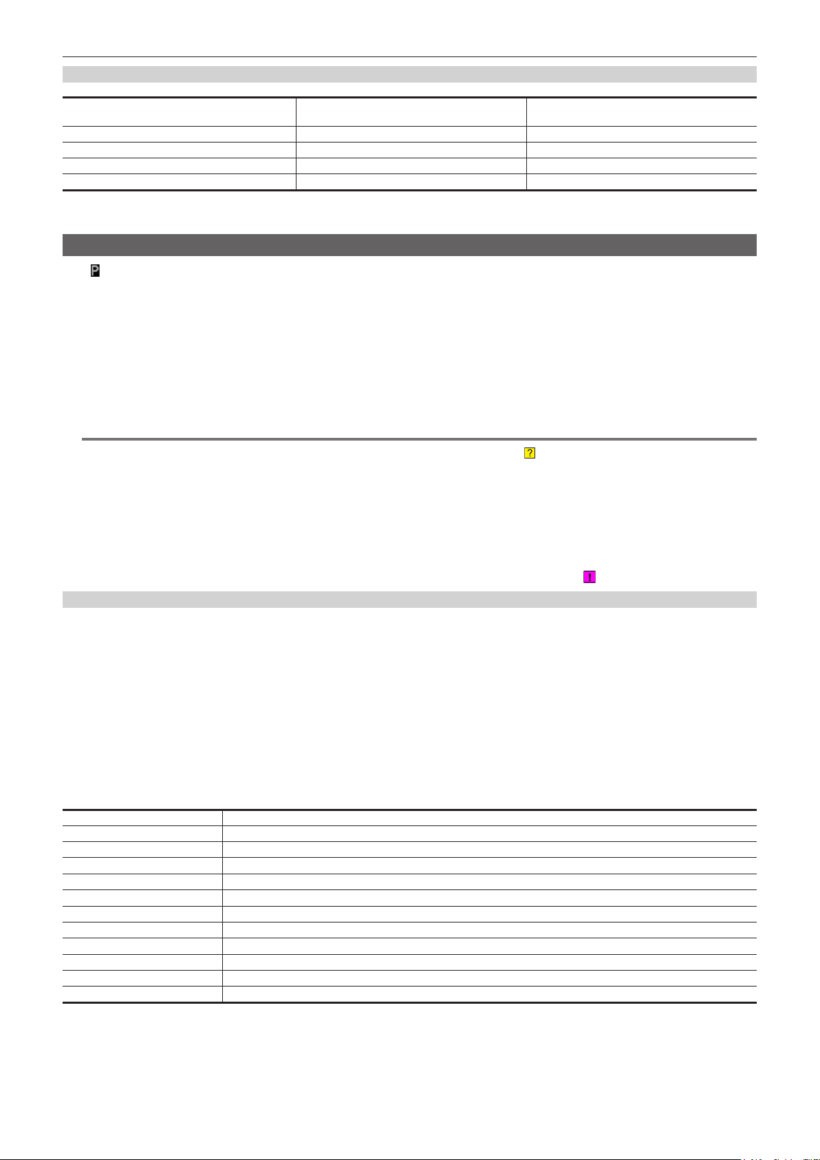
Proxy data recording time (approximate)
Chapter 4 Shooting — Dual codec recording
Recording mode Total recording rate
[AVC-G6 2CH MOV] Approx. 6 Mbps Approx. 13 min
[SHQ 2CH MOV] Approx. 5060 kbps Approx. 25 min
[HQ 2CH MOV] Approx. 1650 kbps Approx. 78 min
[LOW 2CH MOV] Approx. 950 kbps Approx. 135 min
(These are reference values for continuous recording with Panasonic products. The recording time may differ depending on the scene or the number of
clips.)
Recording time
(per 1 GB)
Checking the proxy data
f The indicator is displayed for the material clips with the proxy data recorded.
f The detailed information of the recorded proxy data can be viewed in the clip property.
For details on operations, refer to “Checking detailed information of the proxy data” (page 87).
f The proxy data is recorded to the P2 card or SD memory card as a video/audio le and real-time metadata le.
- Audio le: XXXXXXXX.MOV
- Real-time metadata le: XXXXXXXX.BIN
The time code, user bits, and information are recorded to the frame unit.
Use P2 Viewer Plus to check the proxy data. Some versions of P2 Viewer Plus may not be able to check the data.
For information on P2 Viewer Plus, visit the following website:
http://pro-av.panasonic.net/
NOTE
@@
t Clips with proxy data recorded with the camera are handled as unknown clips by some P2 devices. (unknown clip indicator) is displayed on the
thumbnail, and the following operations become unavailable.
- [DELETE]
- [REPAIR CLIP]
- [RE-CONNECTION]
- [COPY]
- [EXCH. THUMBNAIL]
- Adding and deleting [TEXT MEMO] and [SHOT MARK]
Playback is possible.
On these devices, clips with proxy data made of linked multiple clips are displayed as individual incomplete clips
.
Checking detailed information of the proxy data
Operation methods and panels may differ by version.
Press the <THUMBNAIL> button.
1
The thumbnail screen appears on the viewnder.
Select [CLIP PROPERTY] in the main menu → [CLIP] → [PROPERTY].
2
The clip property screen is displayed.
Use the cursor buttons to select [PROXY].
3
Press the <SET> button.
4
Detailed information about the proxy data is displayed as below.
r Detailed information about proxy data
Item Content of display
[FORMAT] The le format of the recorded data is displayed.
[VIDEO CODEC] Video codec information of the recorded data is displayed.
[VIDEO FRAME RATE] Video frame rate information of the recorded data is displayed.
[VIDEO BIT RATE] Video bitrate information of the recorded data is displayed.
[VIDEO RESOLUTION] The video resolution of the recorded data is displayed.
[ASPECT RATIO] The aspect ratio of the recorded data is displayed.
[TC SUPER] An indication whether the TC (time code) display is superimposed over the recorded video.
[AUDIO CODEC] Audio codec information of the recorded data is displayed.
[AUDIO BIT RATE] Audio bitrate information of the recorded data is displayed.
[AUDIO SAMPLING RATE] Audio sampling rate information of the recorded data is displayed.
[NUM.OF AUDIO CH] The number of audio channels of the recorded data is displayed.
– 87 –
Page 88

Chapter 4 Shooting — Dual codec recording
Error displays about proxy data recordings
If an error occurs during recording the proxy data, check the entries in the following table and take necessary actions.
Error displays
(Viewnder)
[PROXY ERROR] or [PROXY
REC WARNING]
[SD 0 min] Recording of the materials and proxy data will continue.
[SD END] Proxy data recording to the SD memory card will stop, but
[SD WR ERR] Proxy data recording to the SD memory card will stop, but
Stops recording of proxy data. This may also stop recording of
materials.
f An error occurred in the internal proxy module.
[PROXY ERROR]
f A proxy data recording error occurred.
[PROXY REC WARNING]
f If a proxy data recording error occurs, the proxy data currently
being recorded will be processed as below:
- The proxy data being recorded to the P2 card will be
deleted.
- The proxy data being recorded to the SD memory card will
not be restored.
f The remaining SD memory card capacity is getting low.
(approximately shorter than one minute)
recording to the P2 card will continue.
f No SD memory card capacity remains.
recording to the P2 card will continue.
This is displayed when proxy data cannot be recorded in the
SD memory card even when the main menu → [RECORDING
SETUP] → [DUAL CODEC SETTING] → [CODEC USAGE] is
set to [PROXY REC(P2&SD)].
r If the error message is displayed when recording
starts:
f The SD memory card format is different.
f The SD memory card contains 1000 clips or more.
Behavior and cause Action to take
The proxy data will not be properly recorded. Turn off the
camera and turn on it again to check the recording and
playback. If the error continues to occur, please consult your
dealer.
After nishing recording, insert a new SD memory card.
After nishing recording, insert a new SD memory card.
f The proxy data being recorded to the SD memory card will
be deleted.
To restore the deleted proxy data, select clips in the P2 card
and copy them to the SD memory card. (page 88)
Check the status of the SD memory card and insert a
recordable card. (page 86)
r If the error message is displayed during
recording:
f The SD memory card was ejected during recording.
f An error occurred in recording to the SD memory card.
[SD --min] or [SD WP] Proxy data will not be recorded to the SD memory card, but
recording to the P2 card will be performed.
f No SD memory card is inserted. [SD --min]
f The SD memory card is write-protected. [SD WP]
Check the status of the SD memory card.
Copying proxy data to the SD memory card
Press the <THUMBNAIL> button to display the thumbnail screen.
1
Use the cursor buttons to move the cursor to the clip to be copied, and press the <SET> button.
2
Select [SD CARD] in the main menu → [CLIP] → [COPY].
3
Select [YES] in the confirmation message and press the <SET> button.
4
NOTE
@@
t If [SD END] is displayed and the proxy data being recorded to the SD memory card is deleted, perform this procedure to copy the proxy data from the
P2 card, and enable the deleted proxy data to be restored.
t Source data is not copied.
– 88 –
Page 89

Chapter 4 Shooting — Streaming function
Streaming function
You can perform live streaming of audio and video from the camera over the network (wired LAN, wireless LAN, 4G/LTE).
Streaming video from the camera or an application software (e.g. P2 Browser, P2 Streaming Receiver) of a device connected to the camera through a
network is transmitted to a server capable of receiving such signal.
There are two ways to start streaming: streaming from an application software and streaming from the camera.
NOTE
@@
t To display the streaming video in the P2 Browser, start the streaming distribution by operation from the application software. The streaming video
cannot be displayed when operated from the camera.
Setting the network connection
The network settings of the camera are congured according to the settings of application software.
For details on the network connection when starting streaming from the camera or an application software such as P2 Streaming Receiver, refer to
“Connection settings for the streaming function” (page 202).
Using the streaming function
After you nish conguring the network connection, you can congure the streaming function.
Select [STREAMING] in the main menu → [RECORDING SETUP] → [DUAL CODEC SETTING] → [CODEC USAGE].
1
Streaming function is enabled.
Set the streaming mode in the main menu → [RECORDING SETUP] → [DUAL CODEC SETTING] → [STREAMING MODE].
2
f Select either [LOW], [HQ], [AVC-G6], [SHQ (QoS)], or [AVC-G (QoS)].
f For details on combinations of system modes and streaming modes, refer to the table in “List of system modes and supported streaming output”
(page 90).
Set the method for starting streaming.
3
f When starting streaming through operation from an application software
- Select [RECEIVER] in the main menu → [NETWORK SETUP] → [STREAMING SETTING] → [START TRIGGER].
f When starting streaming through operation from the camera
- Select [CAMERA] in the main menu → [NETWORK SETUP] → [STREAMING SETTING] → [START TRIGGER].
- Perform following settings when the streaming mode is set to [SHQ (QoS)] or [AVC-G (QoS)] in Step
Set the main menu → [RECORDING SETUP] → [DUAL CODEC SETTING] → [QoS MAX RATE] and [QoS MIN RATE].
- Set the delay mode during streaming in the main menu → [RECORDING SETUP] → [DUAL CODEC SETTING] → [STREAMING LATENCY].
[NORMAL] is set when the stability of streaming is to be prioritized. [SHORT] is set when reducing of the streaming delay is to be prioritized.
Start streaming.
4
f When starting streaming through operation from an application software
If you started streaming using an application software, the camera starts the transmission of streaming video.
f When starting streaming through operation from the camera
Select [ON] in the main menu → [NETWORK SETUP] → [STREAMING SETTING] → [START].
The transmission of streaming video is started when the camera is connected to to the transmission destination via network.
To stop the transmission of streaming video, select [OFF] in the main menu → [NETWORK SETUP] → [STREAMING SETTING] → [START].
Starting and stopping the transmission of streaming video can be switched using the USER button in which [STREAMING START] is assigned in
the main menu → [USER SW]. During recording, switching is disabled.
NOTE
@@
t To display streaming video using the P2 Browser, VLC Media Player is required for Windows OS and QuickTime Player is required for Mac OS.
However, the P2 Browser does not support the QoS function.
t For details on downloading the video streaming compatible application software and the operating environment, visit the support desk at the following
website:
http://pro-av.panasonic.net/
t The streaming function cannot be used together with the dual codec recording or simultaneous recording.
t The streaming function cannot be used together with the rec during upload function.
t If available bandwidth of the network is low and streaming playback is interrupted, playback condition can be improved by selecting a lower bitrate
mode in [STREAMING MODE], or selecting either [SHQ (QoS)] or [AVC-G (QoS)]. In addition, if [SHQ (QoS)] or [AVC-G (QoS)] is selected, the
terminal that receives streaming data needs to support the QoS function.
t The streaming video from the camera will be a black screen in the playback mode (including the recording check).
2.
– 89 –
Page 90

Chapter 4 Shooting — Streaming function
List of system modes and supported streaming output
The following shows the relationship between system modes and streaming modes on this camera.
f “l”: Supported; “—”: Not supported
[SYSTEM MODE] [STREAMING MODE]
[LINE&FREQ] [REC FORMAT]
[1080-59.94i]
[1080-50i]
[720-59.94P]
[720-50P]
* [LOW] cannot be selected.
[AVC-I100/60i]
[AVC-I50/60i] —
[AVC-G50/60i]
[AVC-G25/60i]
[AVC-I100/50i]
[AVC-I50/50i] —
[AVC-G50/50i]
[AVC-G25/50i]
[AVC-I100/60P]
[AVC-I50/60P] —
[AVC-G50/60P]
[AVC-G25/60P]
[AVC-I100/50P]
[AVC-I50/50P] —
[AVC-G50/50P]
[AVC-G25/50P]
HD streaming
[AVC-G6], [AVC-G (QoS)]
l l
l l
l l
l l
l l
l l
l l*
l l*
l l*
l l*
l l*
l l*
SD streaming
[HQ], [LOW], [SHQ (QoS)]
l
l
l*
l*
List of streaming modes and resolution/frame rates
Streaming mode Resolution Codec Frame rate Bitrate
[AVC-G6]
[HQ]
[LOW]
[AVC-G (QoS)]
[SHQ (QoS)]
*1 When [LINE&FREQ] is [1080-59.94i] or [1080-50i]
*2 When [LINE&FREQ] is [720-60P] or [720-50P]
1920×1080*
1280×720*
640×360
480×270
1920×1080*
1280×720*
960×540
1
2
1
2
Video: H.264 High Prole
Audio: AAC-LC 2ch
Video: H.264 Baseline Prole
Audio: AAC-LC 2ch
Video: H.264 High Prole
Audio: AAC-LC 2ch
Video: H.264 High Prole
Audio: AAC-LC 2ch
30 fps/25 fps
60 fps/50 fps
30 fps/25 fps 1500 kbps
30 fps/25 fps 800 kbps
30 fps/25 fps
60 fps/50 fps
30 fps/25 fps
depending on the application
depending on the application
6 Mbps
Receiving side: Variable
Maximum 9 Mbps
Receiving side: Variable
Maximum 6 Mbps
– 90 –
Page 91

Chapter 4 Shooting — Handling setting data
Handling setting data
Setting data le conguration
[F1:] to [F6:] scene les can be saved internally on the camera according to scene le numbers.
Scene le data ([F1:] to [F6:]) can be saved as a le, and up to eight les can be saved on the SD memory card at a time, which can be loaded and
used.
Setting menu values (including SmartUI setting values) can be saved as one user le on the camera, and can be saved as up to eight user les in the
SD memory card.
Setting data le structure of the camera is as follows.
r Scene le
The camera
[F1:](Factory settings)
[F2:] [F3:] [F4:] [F5:] [F6:]
*1 *1 *1 *1 *1 *1
(Current value)
(Value saved on the camera)
*1 Select [INITIALIZE] in the main menu → [SCENE FILE] → [LOAD/SAVE/INITIALIZE].
By scene le unit as selected in [FILE] in the [CAM02:SCENE FILE] screen of SmartUI
*2 Select [LOAD] or [SAVE] in the main menu → [SCENE FILE] → [LOAD/SAVE/INITIALIZE].
By scene le unit as selected in [FILE] in the [CAM02:SCENE FILE] screen of SmartUI
*3 Select [LOAD] or [SAVE] in the main menu → [CARD FUNCTIONS] → [SCENE FILE].
[F1:] to [F6:] at once
[F1:] [F2:] [F3:] [F4:] [F5:] [F6:]
*2 *2 *2 *2 *2 *2
[F1:] [F2:] [F3:] [F4:] [F5:] [F6:]
r User le
The camera
[USER FILE](Factory settings)
*1
(Current value)
[USER FILE]
SD memory card
Scene file 1
[F1:]
[F2:] [F3:] [F4:] [F5:] [F6:]
*3
Scene file 8
[F1:]
[F2:] [F3:] [F4:] [F5:] [F6:]
SD memory card
User file 1
*3
*2
(Value saved on the camera)
*1 Select [INITIALIZE] in the main menu → [OTHER FUNCTIONS] → [USER FILE].
*2 Select [LOAD] or [SAVE] in the main menu → [OTHER FUNCTIONS] → [USER FILE].
*3 Select [LOAD] or [SAVE] in the main menu → [CARD FUNCTIONS] → [USER FILE].
[USER FILE]
Handling SD memory cards
The SD memory card can be removed and inserted, either before or after the power is turned on.
Inserting SD memory cards
Open the slot cover.
1
User file 8
– 91 –
Page 92

Chapter 4 Shooting — Handling setting data
Insert the SD memory card into the SD memory card slot with the label side of the card upward, and close the slot cover.
2
NOTE
@@
t Before inserting the SD memory card, conrm that the orientation of the SD memory card is correct. If the SD memory card is hard to insert, it may be
reversed or upside-down. Do not force it into the slot. Check the orientation of the card before reinserting it.
t On the camera, use SD memory cards that are compliant with the SD, the SDHC, or the SDXC standards.
t For details on handling SD memory cards, refer to “Cautions when using SD memory cards” (page 22).
Removing SD memory cards
After opening the slot cover and making sure that the busy lamp is not illuminated, push the SD memory card further into the camera and then release.
This releases the SD memory card from the card slot. Remove the SD memory card and close the slot cover.
Note the following points when using or storing memory cards.
f Avoid high temperature and humidity.
f Avoid water droplets.
f Avoid charging with electricity.
Store the SD memory card with the card still inserted into the camera and with the slot cover closed.
Performing operations on SD memory cards
To perform operations such as formatting an SD memory card, writing setting data to an SD memory card, or reading the written data, use [FORMAT SD
CARD] and [SCENE FILE]/[USER FILE] in the main menu → [CARD FUNCTIONS].
If the SD memory card that was formatted in a standard other than the SD/SDHC/SDXC standards on a device other than the camera is inserted,
[LOAD] or [SAVE] operation of the le cannot be performed. Format the SD memory card again.
Formatting SD memory cards
Fig. 1
Select the main menu → [CARD FUNCTIONS] → [FORMAT SD CARD].
1
The conrmation screen is displayed.
Select [YES] in the confirmation screen, and press the <SET> button (or the jog dial button). (Fig. 1)
2
When you do not want to format the memory card, select [NO], and press the <SET> button (or the jog dial button).
When the completion message is displayed, select [OK] and press the <SET> button (or the jog dial button).
3
For details on error messages, refer to “During thumbnail and menu operation” (page 215).
NOTE
@@
t SD memory cards can also be formatted from the thumbnail screen.
For details, refer to “Formatting SD memory cards” (page 122).
t Data deleted as a result of formatting cannot be restored. Always check the data before formatting.
How to use user data
The content of setting data can be written to and read written data from user area on the internal memory of the camera.
Use of this data allows you to quickly reproduce optimum setup states.
Writing setting data to user area
Select [SAVE] in the main menu → [OTHER FUNCTIONS] → [USER FILE].
1
The conrmation screen is displayed.
Select [YES] and press the <SET> button (or the jog dial button).
2
When the completion message is displayed, press the <SET> button (or the jog dial button).
3
– 92 –
Page 93

Chapter 4 Shooting — Handling setting data
Loading written user data
Select [LOAD] in the main menu → [OTHER FUNCTIONS] → [USER FILE].
1
The conrmation screen is displayed.
If [SYSTEM RESTART] is displayed on the conrmation screen, the camera will restart after reading out is complete.
Select [YES] and press the <SET> button (or the jog dial button).
2
Loading of the le begins.
How to use scene le data
The content of setting data can be written to and read written data from scene le area on the internal memory of the camera. Six types of scene les
can be registered. Use of this data allows you to quickly reproduce optimum setup states.
r Factory settings
[F1:]: File that is suitable for standard shooting.
[F2:FLUO.]: The le suitable for shooting when the characteristics of uorescent light should be considered (such as shooting indoors).
[F3:SPARK]: The le that sharpens the color hue and contrast and that has suitable resolution for SD shooting.
[F4:B-STR]: The le suitable for shooting when the tone level of darker areas are to be stretched (such as shooting at sunset).
[F5:CINE V]: The le suitable for shooting cinematic video that has shaper contrast.
[F6:CINE D]: The le suitable for shooting cinematic video that has wider dynamic range.
NOTE
@@
t [SYSTEM MODE] does not change even if the scene le is changed. Set all items in the main menu → [SYSTEM MODE].
Saving scene le setting data to the camera memory
Fig. 1
Select a scene file to save in [FILE] in the [CAM02:SCENE FILE] screen of SmartUI.
1
Select [SAVE] in the main menu → [SCENE FILE] → [LOAD/SAVE/INITIALIZE]. (Fig. 1)
2
A conrmation screen is displayed.
Select [YES] and press the <SET> button (or the jog dial button).
3
The selected scene le is saved to the camera.
Loading the scene le saved in the camera
Select a scene file to load in [FILE] in the [CAM02:SCENE FILE] screen of SmartUI.
1
Select [LOAD] in the main menu → [SCENE FILE] → [LOAD/SAVE/INITIALIZE].
2
The conrmation screen is displayed.
Select [YES] and press the <SET> button (or the jog dial button).
3
The selected scene le is loaded from the camera.
Restoring the scene le setting data to the factory settings
Select the scene file to restore to the factory settings in [FILE] in the [CAM02:SCENE FILE] screen of SmartUI and press the
1
<SET> button (or the jog dial button).
Select [INITIALIZE] in the main menu → [SCENE FILE] → [LOAD/SAVE/INITIALIZE].
2
The conrmation screen is displayed.
– 93 –
Page 94

Chapter 4 Shooting — Handling setting data
Select [YES] and press the <SET> button (or the jog dial button).
3
The selected scene le is restored to the factory settings.
Changing the scene le title
Select the scene file to change the title in [FILE] in the [CAM02:SCENE FILE] screen of SmartUI and press the <SET> button (or
1
the jog dial button).
Select [NAME EDIT] in the main menu → [SCENE FILE].
2
The title entry screen and keyboard are displayed.
Enter the characters you want to set on the keyboard using cursor buttons (or the jog dial button).
3
Select [OK] and press the <SET> button (or the jog dial button).
4
The le name is updated.
How to restore the scene le or menu setting status to the factory settings
All the scene les and menu settings of the camera can be collectively restored to the factory settings.
Select [MENU INITIALIZE] in the main menu → [OTHER FUNCTIONS].
1
Select [EXECUTE] and press the <SET> button (or the jog dial button).
2
[SYSTEM RESTART] indication appears on the conrmation screen.
Select [YES] and press the <SET> button (or the jog dial button).
3
The camera is restarted and data are restored to the factory settings.
Saving to an SD memory card and loading saved data
Scene les and other setting values that you have set can be saved as a le, and up to 8 les can be saved on the SD memory card, and saved data
can be loaded.
f For scene les, the current setting values are saved in the camera automatically, and you can write the saved data to an SD memory card. When they
are loaded from the SD memory card, the current setting values are overwritten as well as the data saved in the camera.
f All scene les [F1:] to [F6:] are overwritten.
Saving scene les
Fig. 1 Fig. 2
Select [SAVE] in the main menu → [CARD FUNCTIONS] → [SCENE FILE]. (Fig. 1)
1
Select the file number (1 to 8) and press the <SET> button (or the jog dial button). (Fig. 2)
2
The title entry screen and keyboard are displayed.
Enter desired characters using cursor buttons (or the jog dial button).
3
Select [OK] on the keyboard and press the <SET> button (or the jog dial button).
4
A conrmation screen is displayed.
Select [YES] and press the <SET> button (or the jog dial button).
5
The le is written with the entered title on the SD memory card, and the screen of Fig. 2 returns.
Loading scene les
Select [LOAD] in the main menu → [CARD FUNCTIONS] → [SCENE FILE].
1
Select the file number (1 to 8) and press the <SET> button (or the jog dial button).
2
A conrmation screen is displayed.
Select [YES] and press the <SET> button (or the jog dial button).
3
When loading is completed, [LOAD OK!] is displayed.
– 94 –
Page 95

Chapter 4 Shooting — Handling setting data
Saving and loading user les
Select [SAVE] or [LOAD] in the main menu → [CARD FUNCTIONS] → [USER FILE]. The operations onward are the same as for scene les.
– 95 –
Page 96

Chapter 4 Shooting — Selection of external reference signal and generator lock setting
Selection of external reference signal and generator lock setting
Locking the video signal to the external reference signal
The video signal output from the camera can be locked to the reference signal supplied from an external source.
The camera can receive external reference signals from the <GL IN/VIDEO OUT> terminal.
Genlocking to the reference signal supplied from the <GL IN/VIDEO OUT> terminal
HD-Y or composite signal that suits the system frame frequency is supplied to the <GL IN/VIDEO OUT> terminal. Select the output signal to lock to the
input reference signal in the main menu → [IN/OUT SEL] → [GENLOCK SETTING] → [GL PHASE] (not available for 480i, 576i).
Adjust the horizontal phase of the reference signal and output signal in the main menu → [IN/OUT SEL] → [GENLOCK SETTING] → [H PHASE].
NOTE
@@
t The subcarrier of the composite signal of the camera is not locked to the subcarrier of the reference signal.
t To set the <GL IN/VIDEO OUT> terminal for genlock input, go to the main menu → [IN/OUT SEL] → [GL IN/VIDEO OUT SEL], and select [GENLOCK
IN].
Output status
The output status changes as follows according to selection of the external reference signal and generator lock setting.
Set [GL PHASE] in the main menu → [IN/OUT SEL] → [GENLOCK SETTING].
Selection of external reference signal Generator lock setting
System mode Input signal [GL PHASE]
HD-Y (1080i)
1080i, 1080P
Composite
HD-Y
720P
Composite
Composite —
480i, 576i
HD-Y —
[HD SDI]
[COMPOSITE]
[HD SDI]
[COMPOSITE]
[HD SDI]
[COMPOSITE]
[HD SDI]
[COMPOSITE]
(phase relationship with external reference signal)
HD SDI output matches the HD-Y input signal.
Down converter output has a delay of approx. 90 H from the HD-Y input
signal.
Down converter output matches the HD-Y input signal.
HD SDI output has an advance of approx. 90 H from the HD-Y input
signal.
HD SDI output matches the composite input signal.
Down converter output has a delay of approx. 90 H from the composite
input signal.
Down converter output matches the composite input signal.
HD SDI output has an advance of approx. 90 H from the composite
input signal.
HD SDI output matches the HD-Y input signal.
Down converter output has a delay of approx. 120 H from the HD-Y
input signal.
Down converter output matches the HD-Y input signal.
HD SDI output has an advance of approx. 120 H from the HD-Y input
signal.
HD SDI output matches the composite input signal.
Down converter output has a delay of approx. 120 H from the composite
input signal.
Down converter output matches the composite input signal.
HD SDI output has an advance of approx. 120 H from the composite
input signal.
SD SDI output matches the composite input signal.
Composite output matches the composite input signal.
SD SDI output is not locked to the HD-Y input signal.
Composite output is not locked to the HD-Y input signal.
Output signal status
NOTE
@@
t The video signal will have genlock when the HD-Y signal is input if the system mode is 720P. In this case, time code may shift by one frame.
t The down converter output represents the output from the <SDI OUT2/IN> terminal.
t When the system mode is 1080/23.98PsF, the genlock can be applied only for HD-Y signal. In this case, regardless of the [GL PHASE] setting, HD
SDI signal output is matched with HD-Y signal.
– 96 –
Page 97

Chapter 4 Shooting — Setting the time data
Setting the time data
The camera provides time codes, user bits, and date and time (real time) data as time data, and they are recorded in the frame in sync with video. They
are also recorded as data for clip metadata les.
Denition of time data
r Time code
Rec run and free run can be switched by [TC_MD] in the [SET01:TC/UB] screen of SmartUI.
f [F-RUN]: The time code always advances even when the power is turned off, and it can be handled in the same way as the actual time. It can also be
slaved to the time code input to the <TC IN/OUT> terminal.
f [R-RUN]: The time code advances only during recording. The number of the previously recorded clip is usually succeeded. The counter value is held
even after the camera is turned off or the P2 card to be recorded to is removed.
NOTE
@@
t In the following case, the values are not continuous.
- When deleting recorded clips
- When switching to 24PN and 30PN (25PN)
- When recording is interrupted due to a malfunction of [REC WARNING], etc. during recording.
r User bits
Two types of user bits are built in.
f LTC UB: Recorded as LTC and output from the <TC IN/OUT> terminal. It is also output as LTC of the HD SDI signal.
f VITC UB: Recorded as VITC (recorded to VIDEO AUX area by DVCPRO). It is also output as VITC of the HD SDI signal.
LTC UB can select and record user set values, time, year/month/day, the same value as time codes, camera frame rate information, and input value of
external signals from the <TC IN/OUT> terminal, etc.
VITC UB records the camera frame rate information.
The LTC UB value of the recording start time can be recorded on the user bits of the clip metadata.
r Date/time (real time)
f By means of the internal clock, year, month, day, and time can be displayed in the viewnder and on the image output from the <SDI OUT2/IN>
terminal, <GL IN/VIDEO OUT> terminal, and <HDMI> terminal, etc.
f The internal clock is used for measuring the free run time code while the power is off and as time and year/month/day data of the user bits. It is also
used as the reference for le generation times during clip recording, which determine the sorting order of thumbnails and the order of playback.
f It is also used to generate clip metadata and UMID (Unique Material Identier).
For details, refer to “Setting the date/time of the internal clock” (page 43).
Recording of time codes and user bits
Recording of time codes
Setting Recording TC
[LINE&FREQ] [REC FORMAT] [CAMERA MODE] LTC VITC
[1080-59.94P]
[1080-59.94i]
[1080-50P]
[1080-50i]
[AVC-I100/60P]
[AVC-G25/60P]
[AVC-G12/60P]
[AVC-I100/30PN]
[AVC-G50/30PN]
[AVC-G25/30PN]
[AVC-G12/30PN]
[AVC-I100/24PN]
[AVC-G50/24PN]
[AVC-G25/24PN]
[AVC-G12/24PN]
[AVC-I100/60i]
[AVC-I50/60i]
[AVC-G50/60i]
[AVC-G25/60i]
[AVC-G12/60i]
[DVCPRO HD/60i]
[AVC-I100/50P]
[AVC-G25/50P]
[AVC-G12/50P]
[AVC-I100/25PN]
[AVC-G50/25PN]
[AVC-G25/25PN]
[AVC-G12/25PN]
[AVC-I100/50i]
[AVC-I50/50i]
[AVC-G50/50i]
[AVC-G25/50i]
[AVC-G12/50i]
[DVCPRO HD/50i]
—
—
—
—
Recording run/free run*
[DF]/[NDF]
30 frames
Recording run/free run*
[DF]/[NDF]
30 valid frames
Recording run/free run*
[NDF]
24 valid frames
Recording run/free run*
[DF]/[NDF]
30 frames
Recording run/free run*
25 frames
Recording run/free run*
25 valid frames
Recording run/free run*
25 frames
Same value as LTC
Same value as LTC
Same value as LTC
Same value as LTC
– 97 –
Page 98
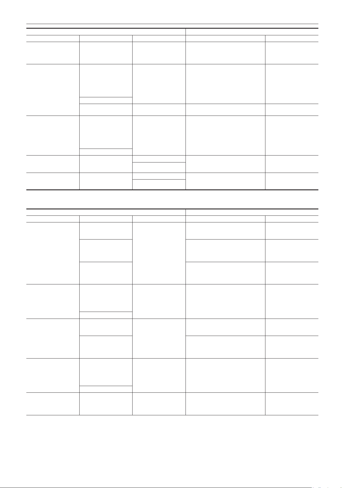
Chapter 4 Shooting — Setting the time data
Setting Recording TC
[LINE&FREQ] [REC FORMAT] [CAMERA MODE] LTC VITC
[AVC-I100/24PN]
[1080-23.98PsF]
[720-59.94P]
[720-50P]
[480-59.94i]
[576-50i]
* For free run, the time code is slaved to the input TC of the <TC IN/OUT> terminal.
[AVC-G50/24PN]
[AVC-G25/24PN]
[AVC-G12/24PN]
[AVC-I100/60P]
[AVC-I50/60P]
[AVC-G50/60P]
[AVC-G25/60P]
[AVC-G12/60P]
[AVC-I100/30PN]
[DVCPRO HD/60P]
[AVC-I100/24PN] —
[AVC-I100/50P]
[AVC-I50/50P]
[AVC-G50/50P]
[AVC-G25/50P]
[AVC-G12/50P]
[AVC-I100/25PN]
[DVCPRO HD/50P]
[DVCPRO50/60i]
[DVCPRO/60i]
[DV/60i]
[DVCPRO50/50i]
[DVCPRO/50i]
[DV/50i]
—
—
—
[60i] Recording run/free run*
[30P]
[50i]
[25P]
Recording run/free run*
[NDF]
24 frames
Recording run/free run*
[DF]/[NDF]
30 frames
Recording run/free run*
24 frames
Recording run/free run*
25 frames
[DF]/[NDF]
30 frames
Recording run/free run*
25 frames
Same value as LTC
Same value as LTC
Same value as LTC
Same value as LTC
Same value as LTC
(No recording in [DV/60i]/
Same value as LTC
(No recording in [DV/60i]/
Output of time codes
Setting Output TC
[LINE&FREQ] [REC FORMAT] [CAMERA MODE] TC OUT LTC, VITC of HD SDI
[AVC-I100/60P]
[1080-59.94P]
[1080-59.94i]
[1080-50P]
[1080-50i]
[1080-23.98PsF]
[AVC-G25/60P]
[AVC-G12/60P]
[AVC-I100/30PN]
[AVC-G50/30PN]
[AVC-G25/30PN]
[AVC-G12/30PN]
[AVC-I100/24PN]
[AVC-G50/24PN]
[AVC-G25/24PN]
[AVC-G12/24PN]
[AVC-I100/60i]
[AVC-I50/60i]
[AVC-G50/60i]
[AVC-G25/60i]
[AVC-G12/60i]
[DVCPRO HD/60i]
[AVC-I100/50P]
[AVC-G25/50P]
[AVC-G12/50P]
[AVC-I100/25PN]
[AVC-G50/25PN]
[AVC-G25/25PN]
[AVC-G12/25PN]
[AVC-I100/50i]
[AVC-I50/50i]
[AVC-G50/50i]
[AVC-G25/50i]
[AVC-G12/50i]
[DVCPRO HD/50i]
[AVC-I100/24PN]
[AVC-G50/24PN]
[AVC-G25/24PN]
[AVC-G12/24PN]
—
LTC is converted to 30 frames and output.
— LTC is output. LTC is output.
—
— LTC is output. LTC is output.
— LTC is output. LTC is output.
LTC is output. LTC is output.
LTC is output. LTC is output.
LTC is converted to 30
frames and output.
LTC is output. LTC is output.
LTC is output. LTC is output.
[DV/50i])
[DV/50i])
– 98 –
Page 99
Chapter 4 Shooting — Setting the time data
Setting Output TC
[LINE&FREQ] [REC FORMAT] [CAMERA MODE] TC OUT LTC, VITC of HD SDI
[AVC-I100/60P]
[AVC-I50/60P]
[AVC-G50/60P]
[720-59.94P]
[AVC-G25/60P]
[AVC-G12/60P]
[AVC-I100/30PN]
— LTC is output. LTC is output.
[DVCPRO HD/60P]
[AVC-I100/24PN] — LTC is converted to 30 frames and output.
LTC is converted to 30
frames and output.
[AVC-I100/50P]
[AVC-I50/50P]
[AVC-G50/50P]
[720-50P]
[AVC-G25/50P]
[AVC-G12/50P]
— LTC is output. LTC is output.
[AVC-I100/25PN]
[DVCPRO HD/50P]
[480-59.94i]
[576-50i]
[DVCPRO50/60i]
[DVCPRO/60i]
[DV/60i]
[DVCPRO50/50i]
[DVCPRO/50i]
[DV/50i]
[60i]
[30P]
[50i]
[25P]
LTC is output. None
LTC is output. None
Recording of user bits
Setting Recording TC
[LINE&FREQ] [REC FORMAT] [CAMERA MODE] LTC UB VITC UB
[AVC-I100/60P]
[AVC-G25/60P]
Follows [VITC UBG MODE]
[AVC-G12/60P]
[AVC-I100/30PN]
[1080-59.94P]
[AVC-G50/30PN]
[AVC-G25/30PN]
[AVC-G12/30PN]
[AVC-I100/24PN]
— Follows [UBG MODE]*
1
Frame information lock
[AVC-G50/24PN]
[AVC-G25/24PN]
[AVC-G12/24PN]
[AVC-I100/60i]
[AVC-I50/60i]
[1080-59.94i]
[AVC-G50/60i]
[AVC-G25/60i]
— Follows [UBG MODE]*
1
Follows [VITC UBG MODE]
[AVC-G12/60i]
[DVCPRO HD/60i]
[AVC-I100/50P]
[AVC-G25/50P]
Follows [VITC UBG MODE]
[AVC-G12/50P]
[1080-50P]
[AVC-I100/25PN]
[AVC-G50/25PN]
[AVC-G25/25PN]
— Follows [UBG MODE]*
1
Frame information lock
[AVC-G12/25PN]
[AVC-I100/50i]
[AVC-I50/50i]
[1080-50i]
[AVC-G50/50i]
[AVC-G25/50i]
— Follows [UBG MODE]*
1
Follows [VITC UBG MODE]
[AVC-G12/50i]
[DVCPRO HD/50i]
[AVC-I100/24PN]
[1080-23.98PsF]
[AVC-G50/24PN]
[AVC-G25/24PN]
— Follows [UBG MODE] Frame information lock
[AVC-G12/24PN]
[AVC-I100/60P]
[AVC-I50/60P]
[AVC-G50/60P]
[720-59.94P]
[AVC-G25/60P]
[AVC-G12/60P]
— Follows [UBG MODE]*
1
Frame information lock
[AVC-I100/30PN]
[AVC-I100/24PN]
[DVCPRO HD/60P]
– 99 –
Page 100

Chapter 4 Shooting — Setting the time data
Setting Recording TC
[LINE&FREQ] [REC FORMAT] [CAMERA MODE] LTC UB VITC UB
[AVC-I100/50P]
[AVC-I50/50P]
[AVC-G50/50P]
[720-50P]
[AVC-G25/50P]
[AVC-G12/50P]
— Follows [UBG MODE]*
1
Frame information lock
[AVC-I100/25PN]
[DVCPRO HD/50P]
[480-59.94i]
[576-50i]
[DVCPRO50/60i]
[DVCPRO/60i]
[DV/60i]
[DVCPRO50/50i]
[DVCPRO/50i]
[DV/50i]
[60i]
[30P]
[50i]
[25P]
Follows [UBG MODE]*
Follows [UBG MODE]*
1
1
Follows [VITC UBG
MODE]*
Follows [VITC UBG
MODE]*
*1 With [EXT], UB of the <TC IN/OUT> terminal is slaved.
*2 When [CAMERA MODE] is set to [30P] and [25P], frame rate information will be xed.
Output of user bits
Setting Output UB
[LINE&FREQ] [REC FORMAT] [CAMERA MODE] UB for TC OUT LTC UB for HD SDI VITC UB for HD SDI
[AVC-I100/60P]
[AVC-G25/60P]
[AVC-G12/60P]
[AVC-I100/30PN]
LTC UB is output. LTC UB is output.
[AVC-G50/30PN]
[1080-59.94P]
[AVC-G25/30PN]
—
VITC UB is output.
[AVC-G12/30PN]
[AVC-I100/24PN]
[AVC-G50/24PN]
[AVC-G25/24PN]
Outputs along to over
60P, based on LTC UB.
Outputs along to over
60P, based on LTC UB.
[AVC-G12/24PN]
[AVC-I100/60i]
[AVC-I50/60i]
[1080-59.94i]
[AVC-G50/60i]
[AVC-G25/60i]
— LTC UB is output. LTC UB is output. VITC UB is output.
[AVC-G12/60i]
[DVCPRO HD/60i]
[AVC-I100/50P]
[AVC-G25/50P]
[AVC-G12/50P]
[1080-50P]
[AVC-I100/25PN]
— LTC UB is output. LTC UB is output. VITC UB is output.
[AVC-G50/25PN]
[AVC-G25/25PN]
[AVC-G12/25PN]
[AVC-I100/50i]
[AVC-I50/50i]
[1080-50i]
[AVC-G50/50i]
[AVC-G25/50i]
— LTC UB is output. LTC UB is output. VITC UB is output.
[AVC-G12/50i]
[DVCPRO HD/50i]
[AVC-I100/24PN]
[1080-23.98PsF]
[AVC-G50/24PN]
[AVC-G25/24PN]
— LTC UB is output. LTC UB is output. LTC UB is output.
[AVC-G12/24PN]
[AVC-I100/60P]
[AVC-I100/30PN]
[AVC-I50/60P]
[720-59.94P]
[AVC-G50/60P]
[AVC-G25/60P]
[AVC-G12/60P]
—
LTC UB is output. LTC UB is output.
VITC UB is output.
[DVCPRO HD/60P]
[AVC-I100/24PN]
Outputs along to over
60P, based on LTC UB.
Outputs along to over
60P, based on LTC UB.
[AVC-I100/50P]
[AVC-I100/25PN]
[AVC-I50/50P]
[720-50P]
[AVC-G50/50P]
[AVC-G25/50P]
— LTC UB is output. LTC UB is output. VITC UB is output.
[AVC-G12/50P]
[DVCPRO HD/50P]
[480-59.94i]
[DVCPRO50/60i]
[DVCPRO/60i]
[DV/60i]
[60i]
[30P]
LTC UB is output. None None
2
2
– 100 –
 Loading...