

Page 1
Operating Instructions
Memory Card Camera-Recorder
Model No. AJ-PX270
Before operating this product, please read the instructions carefully and save this manual for future use.
W0214HM0 -YI
ENGLISH
VQT5J83A(E)
Page 2
Read this rst!
Read this rst!
indicates safety information.
CAUTION
RISK OF ELECTRIC SHOCK
DO NOT OPEN
CAUTION: TO REDUCE THE RISK OF ELECTRIC SHOCK,
DO NOT REMOVE COVER (OR BACK).
NO USER-SERVICEABLE PARTS INSIDE.
REFER TO SERVICING TO QUALIFIED SERVICE PERSONNEL.
The lightning flash with arrowhead symbol,
within an equilateral triangle, is intended to
alert the user to the presence of uninsulated
“dangerous voltage” within the product’s
enclosure that may be of sufficient magnitude
to constitute a risk of electric shock to
persons.
The exclamation point within an equilateral
triangle is intended to alert the user to
the presence of important operating and
maintenance (servicing) instructions in the
literature accompanying the appliance.
WARNING:
• To reduce the risk of fire or electric shock, do not
expose this equipment to rain or moisture.
• To reduce the risk of fire or electric shock, keep
this equipment away from all liquids. Use and
store only in locations which are not exposed
to the risk of dripping or splashing liquids, and
do not place any liquid containers on top of the
equipment.
CAUTION:
The mains plug of the power supply cord shall
remain readily operable.
The AC receptacle (mains socket outlet) shall be
installed near the equipment and shall be easily
accessible.
To completely disconnect this equipment from the
AC mains, disconnect the power cord plug from
the AC receptacle.
CAUTION:
Danger of explosion or fire if battery is incorrectly
replaced or mistreated.
• Do not disassemble the battery or dispose of it
in fire.
• Do not store in temperatures over 60°C (140°F).
• Do not expose the battery to excessive heat
such as sunshine, fire or the like.
For Battery Pack
• Use specified charger.
• Replace only with same or specified type.
CAUTION:
In order to maintain adequate ventilation, do
not install or place this unit in a bookcase, builtin cabinet or any other confined space. To
prevent risk of electric shock or fire hazard due to
overheating, ensure that curtains and any other
materials do not obstruct the ventilation.
WARNING:
Always keep memory cards (optional accessory)
or accessories (microphone holder screws) out of
the reach of babies and small children.
CAUTION:
To reduce the risk of fire or electric shock and
annoying interference, use the recommended
accessories only.
CAUTION:
Do not jar, swing, or shake the unit by its handle
while the conversion lens or another accessory is
attached.
Due to the added weight of the conversion lens,
any strong jolt to the handle may damage the unit
or result in personal injury.
CAUTION:
Do not lift the unit by its handle while the tripod is
attached. When the tripod is attached, its weight
will also affect the unit’s handle, possibly causing
the handle to break and hurting the user. To carry
the unit while the tripod is attached, take hold of
the tripod.
CAUTION:
Excessive sound pressure from earphones and
headphones can cause hearing loss.
CAUTION:
Do not leave the unit in direct contact with the skin
for long periods of time when in use.
Low temperature burn injuries may be suffered if
the high temperature parts of this unit are in direct
contact with the skin for long periods of time.
When using the equipment for long periods of
time, make use of the tripod.
CAUTION (For USA and Canada):
To prevent electric shock, match wide blade of
plug to wide slot, fully insert.
– 2 –
Page 3
Read this rst!
indicates safety information.
CAUTION:
Keep metal objects (such as necklaces and
hairpins) away from the battery.
Short-circuiting may occur across the terminals,
causing the battery to heat up, and you may
seriously burn yourself if you touch the battery in
this state.
CAUTION:
A coin type battery is installed inside of the unit.
Do not store the unit in temperatures over 60 °C
(140 °F).
Do not leave the unit in an automobile exposed to
direct sunlight for a long period of time with doors
and windows closed.
CAUTION:
This apparatus can be operated at a voltage in the range of 100-240 V AC.
Voltages other than 120 V are not intended for U.S.A. and Canada.
Operation at a voltage other than 120 V AC may require the use of a different AC plug. Please contact either
a local or foreign Panasonic authorized service center for assistance in selecting an alternate AC plug.
FCC NOTICE (USA)
Declaration of Conformity
Model Number: AJ-PX270
Trade Name: Panasonic
Responsible Party: Panasonic Corporation of North America
Two Riverfront Plaza, Newark, NJ 07102
Support contact: 1-800-524-1448
This device complies with Part 15 of the FCC Rules.
Operation is subject to the following two conditions:
(1) This device may not cause harmful interference, and (2) this device must accept any interference
received, including interference that may cause undesired operation.
To assure continued compliance, follow the attached installation instructions and do not make any
unauthorized modifications.
CAUTION:
This equipment has been tested and found to comply with the limits for a Class B digital device, pursuant
to Part 15 of the FCC Rules. These limits are designed to provide reasonable protection against harmful
interference in a residential installation. This equipment generates, uses and can radiate radio frequency
energy and, if not installed and used in accordance with the instructions, may cause harmful interference
to radio communications. However, there is no guarantee that interference will not occur in a particular
installation. If this equipment does cause harmful interference to radio or television reception, which
can be determined by turning the equipment off and on, the user is encouraged to try to correct the
interference by one of the following measures:
• Reorient or relocate the receiving antenna.
• Increase the separation between the equipment and receiver.
• Connect the equipment into an outlet on a circuit different from that to which the receiver is connected.
• Consult the dealer or an experienced radio/TV technician for help.
The user may find the booklet “Something About Interference”
available from FCC local regional offices helpful.
FCC Warning:
To assure continued FCC emission limit compliance, follow the attached installation instructions and the
user must use only shielded interface cables when connecting to host computer or peripheral devices.
Also, any unauthorized changes or modifications to this equipment could void the user’s authority to
operate this device.
– 3 –
Page 4
Read this rst!
indicates safety information.
NOTIFICATION (Canada)
CAN ICES-3(B)/NMB-3(B)
The rating plate is on the underside of the Camera Recorder, Battery Charger and AC Adaptor.
IMPORTANT SAFETY INSTRUCTIONS
1) Read these instructions.
2) Keep these instructions.
3) Heed all warnings.
4) Follow all instructions.
5) Do not use this apparatus near water.
6) Clean only with dry cloth.
7) Do not block any ventilation openings. Install in accordance with the manufacturer’s instructions.
8) Do not install near any heat sources such as radiators, heat registers, stoves, or other apparatus (including amplifiers) that
produce heat.
9) Do not defeat the safety purpose of the polarized or grounding-type plug. A polarized plug has two blades with one wider
than the other. A grounding-type plug has two blades and a third grounding prong. The wide blade or the third prong are
provided for your safety. If the provided plug does not fit into your outlet, consult an electrician for replacement of the
obsolete outlet.
10) Protect the power cord from being walked on or pinched particularly at plugs, convenience receptacles, and the point
where they exit from the apparatus.
11) Only use attachments/accessories specified by the manufacturer.
12) Use only with the cart, stand, tripod, bracket, or table specified by the manufacturer, or sold with the apparatus.
When a cart is used, use caution when moving the cart/ apparatus combination to avoid injury from tip-over.
13) Unplug this apparatus during lightning storms or when unused for long periods of time.
14) Refer all servicing to qualified service personnel. Servicing is required when the apparatus has been damaged
in any way, such as power-supply cord or plug is damaged, liquid has been spilled or objects have fallen into the
apparatus, the apparatus has been exposed to rain or moisture, does not operate normally, or has been dropped.
For USA
A lithium ion/polymer battery that is recyclable powers the product you have purchased.
Please call 1-800-8-BATTERY for information on how to recycle this battery.
– 4 –
Page 5
Read this rst!
Brazil Only
Brasil Apenas
rManuseio de baterias usadas
BRASIL
Após o uso, as pilhas e /ou baterias poderão
ser entregues ao estabelecimento comercial
ou rede de assistência técnica autorizada.
Cobrir os terminais positivo (+) e negativo (-) com uma fita isolante adesiva, antes de depositar numa caixa
destinada para o recolhimento. O contato entre partes metálicas pode causar vazamentos, gerar calor, romper a
blindagem e produzir fogo.
Não desmonte, não remova o invólucro, nem amasse a bateria. O gás liberado pela bateria pode irritar a
garganta, danificar o lacre do invólucro ou o vazamento provocar calor, ruptura da blindagem e produzir fogo
devido ao curto circuito dos terminais. Não incinere nem aqueça as baterias, elas não podem ficar expostas a
temperaturas superiores a 100°C (212°F). O gás liberado pela bateria pode irritar a garganta, danificar o lacre
do invólucro ou o vazamento provocar calor, ruptura da blindagem e produzir fogo devido ao curto circuito dos
terminais provocado internamente.
Evite o contato com o liquido que vazar das baterias. Caso isto ocorra, lave bem a parte afetada com bastante
água. Caso haja irritação, consulte um médico.
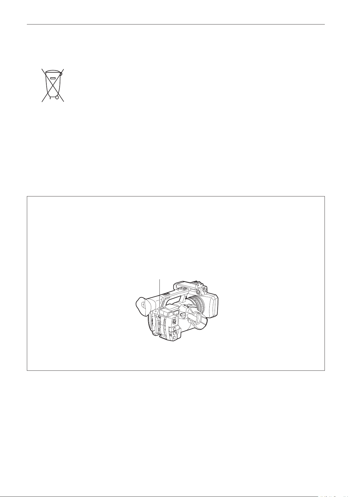
To remove the battery
Para remover a bateria
Main Power Battery (Lithium ion Battery)
Bateria Principal de Energia
(Refer to page 27 for the detail.)
Press the battery release button.
Pressione o botão para liberar a bateria.
Battery release button
Botão de liberação da bateria
Back-up Battery (Lithium Battery)
• For the removal of the battery for disposal at the end of its service life, please consult your dealer.
– 5 –
Page 6

Read this rst!
rBatteries that may be used with this product (Correct as of March 2014)
Panasonic VW-VBD58 batteries may be used with this product.
It has been found that counterfeit battery packs which look very similar to the genuine product are made
available to purchase in some markets. Some of these battery packs are not adequately protected with internal
protection to meet the requirements of appropriate safety standards. There is a possibility that these battery
packs may lead to fire or explosion. Please be advised that we are not liable for any accident or failure occurring
as a result of use of a counterfeit battery pack. To ensure that safe products are used we would recommend that
a genuine Panasonic battery pack is used.
Battery Charger / AC Adaptor
Disconnect the AC mains plug from the AC mains socket when not in use.
– 6 –
Page 7

f SDXC logo is a trademark of SD-3C, LLC.
f HDMI, HDMI logo, and High-Denition Multimedia Interface are trademarks or registered trademarks of HDMI Licensing LLC in the United States and/
or other countries.
f MMC (Multi Media Card) is a registered trademark of Inneon Technologies AG.
f Microsoft
f Screenshots are used according to Microsoft Corporation guidelines.
f Apple, Macintosh, Mac OS, QuickTime, iPad, and iPhone are trademarks or registered trademarks of Apple Inc. in the United States and/or other
countries.
f Java and all Java-based trademarks are trademarks or registered trademarks of Sun Microsystems, Inc. in the United States.
f All other names, company names, product names, etc., contained in this instruction manual are trademarks or registered trademarks of their
respective owners.
f This product is licensed under the AVC Patent Portfolio License. All other acts are not licensed except private use for personal and non-prot purposes
such as what are described below.
f Use of DCF Technologies under license from Multi-Format, Inc.
®
and Windows® are registered trademarks or trademarks of Microsoft Corporation in the United States and/or other countries.
- To record video in compliance with the AVC standard (AVC Video)
- To play back AVC Video that was recorded by a consumer engaged in a personal and non-commercial activity
- To play back AVC Video that was obtained from a video provider licensed to provide the video
Visit the MPEG LA, LLC website (http://www.mpegla.com/) for details.
How to read this document
r Illustrations
f Illustrations of the camera, menu screens, and other items, may vary from the actual items.
r Conventions used in this manual
f Words and phrases in [ ] brackets indicate details and content displayed in the viewnder or LCD monitor.
f Words and phrases in < > brackets indicate design text used on this camera, such as button names.
r Reference pages
f Reference pages in this document are indicated by (page 00).
r Terminology
f SD memory card, SDHC memory card, and SDXC memory card are referred to as “SD memory card”.
f A memory card with the “P2” logo such as AJ-P2E064AG memory card (optional) is referred to as a “P2 memory card”.
f A memory card with the “microP2” logo such as AJ-P2M032AG memory card (optional) is referred to as a “microP2 memory card”.
f P2 memory card and microP2 memory card are referred to only as “P2 card” unless distinguished otherwise.
f Media such as external hard disk drives (HDD) connected to USB are referred to as “storage devices”.
f Video that is created during a single recording operation is referred to as a “clip”.
– 7 –
Page 8

Contents
Contents
Read this rst! 2
Chapter 1 Overview 10
Before using the camera 11
Use of the camera on a system 13
Basic conguration devices 13
Expanded conguration devices 13
What you can do with this camera 14
Recording to the memory card 14
Linking to external devices 14
Connecting to the network 15
Chapter 2 Description of Parts 16
Left side 17
Right side 19
Front side, rear side 21
Top side 2 3
Chapter 3 Preparation 25
Power supply 26
Charging the battery 26
Attaching and removing the battery 27
Using the AC adaptor 27
Attaching and adjusting accessories 29
Adjusting the grip strap 29
Attaching the shoulder strap 29
Attaching the lens hood 29
Attaching the eye cup 30
Attaching the front microphone 31
Attaching a tripod 31
Turning on/off the power 32
How to turn on the power 32
How to turn off the power 32
Setting the date/time of the internal clock 33
P2 card 34
Inserting a P2 card 34
Removing a P2 card 35
Preventing accidental erasure 35
P2 card access LEDs and status of P2 cards 35
P2 card recording time 36
CPS (Content Protection System) 37
How to handle data recorded on P2 cards 37
Assigning functions to the USER buttons 38
Adjusting and setting the LCD monitor 40
Using the LCD monitor 40
Adjusting the LCD monitor 40
Mirror shooting 40
Highlighting the outlines of images 40
Adjusting and setting the viewnder 41
Using the viewnder 4 1
Adjusting the viewnder 41
Highlighting the outlines of images 41
Tally lamp 4 2
Chapter 4 Shooting 43
Basic procedures 44
Preparation 4 4
Shooting 44
Selecting the resolution, codec, and video format for recording 45
Adjustable settings when shooting 47
Iris 47
Gain 4 7
Super gain 47
Brightness adjustment 47
Macro 47
Focusing (manual focus) 47
Focus assist function 48
Area mode function 49
Level gauge function 50
Adjusting the white and black balance 51
Adjusting the white balance 51
Adjusting the black balance 52
Using the zoom function 54
Setting the <ZOOM> switch 54
Adjusting the zoom position 5 4
Zoom ring 54
Adjusting image quality 55
Detail function 55
Skin tone function 55
RB gain control function 56
Chroma setting function 56
Matrix function 56
Color correction function 57
Black control function 5 7
Gamma function 57
Knee function 57
High color function 58
White clip function 58
Setting the electronic shutter 59
Shutter mode 59
Adjusting with the <SEL/PUSH SET> dial button and <MODE/
MENU CANCEL> button 5 9
Flash band compensation (FBC) function 60
Setting the ash band compensation function 60
Variable frame rate (VFR) recording function 61
Native variable frame rate recording 61
Standard variable frame rate recording (pull-down recording) 61
Selecting audio input and adjusting recording levels 63
Selecting audio input signals 63
Using the built-in microphone 63
Using the external microphone and audio device 63
Adjusting the recording level 64
Displaying the audio level detailed 64
Getting position information using the GPS 65
Special recording functions
Pre-recording 66
Interval recording 6 6
One-shot recording 67
Loop recording 67
One-clip recording 68
Simultaneous recording 69
Hot swap recording 69
Recording check function 70
Shot mark recording function 70
Text memo recording function 7 0
6 6
Convenient shooting functions 71
Low angle shooting 7 1
Scan reverse shooting 71
Zebra patterns display 71
Displaying the center marker 71
Displaying the safety zone marker 7 1
Displaying frame marker 72
Checking and displaying the shooting status 72
Changing image size 72
Image stabilization function 7 2
Dynamic range stretcher function 72
Backlight compensation 72
Color bars 72
Time stamp function 72
Deleting last clip function 73
Waveform monitor function 73
Direct menu operation 7 3
Multi formats 74
Selecting recording signals 7 4
System modes and recording functions 74
List of recording settings and recording functions 76
Selecting video output 7 7
Recording/playback and output format list 7 8
Dual codec recording 79
Dual codec recording setting 79
Recording the proxy data 79
Recording to the SD memory card 79
Checking the proxy data 80
Error displays about proxy data recordings 81
Handling setting data 8 3
Setting data le conguration 8 3
Handling SD memory cards 8 3
Performing operations on SD memory cards 84
How to use user data 85
How to use scene le data 8 5
How to restore the scene le or menu setting status to the
factory settings 87
Saving to an SD memory card and loading saved data 87
Selection of external reference signal and generator lock
setting 88
– 8 –
Page 9

Contents
Locking the video signal to the external reference signal 88
Setting the time data 89
Recording of time codes and user bits 89
User bits settings 92
How to input user bits 93
Setting the time code 93
Externally locking the time code 94
Supplying the time code externally 96
Connecting and setting the genlock and time code input/output 96
Setting and displaying the counter 9 7
Chapter 5 Playback 98
Basic procedures 99
Preparation 99
Playback 99
Thumbnail operations 100
Thumbnail operation overview 100
Thumbnail screen 100
Selecting thumbnails 102
Setting thumbnail screen display 102
Changing thumbnails 103
Shot mark 104
Text memo 104
Deleting clips 105
Restoring clips 105
Reconnecting incomplete clips 106
Copying clips 106
Setting clip metadata
Formatting a P2 card 108
Formatting SD memory cards 109
Properties
106
109
Chapter 6 Menu Operations 114
Setting menu structure 1 1 5
Menu types and how to open them 11 5
Main menu structure 115
Setting menu display 11 6
Setting menu basic operations 116
Setting [USER MENU] 117
Setting menu initialization 117
Menu list 11 9
[SCENE FILE] 11 9
[SYSTEM MODE] 124
[USER SW] 125
[SW MODE] 126
[AUTO SW] 127
[RECORDING SETUP] 128
[CLIP] 129
[AUDIO SETUP] 131
[OUTPUT SEL] 132
[NETWORK SETUP] 134
[DISPLAY SETUP] 135
[CARD FUNCTIONS] 138
[OTHER FUNCTIONS] 138
[MAINTENANCE] 138
[DIAGNOSTIC] 139
[USER MENU SEL] 139
Connecting to a computer in the USB device mode 152
Connecting to external devices in USB host mode 152
Chapter 9 Network Connection 161
Network connection 162
Available functions 162
Operating environment 162
Preparing for connection 163
For wireless LAN 163
For wired LAN 164
Network settings 165
Wireless LAN settings 165
Wired LAN settings 166
P2 browser function settings and connection status check 168
FTP client function setting 168
Using FTP client function 170
FTP server folder list (FTP explorer screen) 170
Deleting clips on the FTP server 171
Viewing information of clips on FTP server 171
Transferring from a P2 card to an FTP server (copy) 172
Writing back from an FTP server to a P2 card (copy) 172
Transferring from an SD card to an FTP server (export) 172
Writing back from an FTP server to an SD memory card
(import) 173
Chapter 10 Maintenance and Inspection 174
Maintenance 175
Charging the built-in battery 175
Frequently asked questions 176
Power supply 176
Battery 176
Shooting 176
Editing 176
Playback 176
Others 177
Warning system 178
Cases indicated by error codes 178
Cases indicated by error messages 178
Updating the camera rmware 182
Cleaning and storing 183
Cleaning the camera recorder 183
Cautions when storing the camera recorder 183
Chapter 11 Specication 184
Specications 185
Dimensions 185
Specications 185
Index 190
[OPTION MENU] list 140
[AREA SELECT] 140
[AWB PRE CONTROL] 140
[CAM REMOTE ADJ.] 140
[ENG SECURITY] 140
Chapter 7 Display 141
Screen status display 142
Conguration of status display on screen 142
Selecting display items on screen 142
Displaying screen 142
Checking and displaying shooting status 146
Mode check display 147
Chapter 8 Connecting to External Devices 149
Connecting with headphones, remote control, or TV/
monitor 150
Headphones 150
Remote control 150
TV/monitor 150
Connection function via <USB2.0 DEVICE> or <USB3.0
HOST> terminal 152
– 9 –
Page 10

Chapter 1 Overview
Before using the camera, read this chapter.
For accessories, refer to the leaet supplied with the product.
Page 11

Chapter 1 Overview — Before using the camera
Before using the camera
r When using this product during rain or snow or when at the beach, be careful that water does not get inside the camera recorder.
Water causes damage to the camera recorder and memory card. (Repair may be impossible)
r Keep the camera recorder away from devices (TVs, TV games, etc.) that produce magnetism.
f If you use the camera recorder on or near TVs, video and sound data may be distorted by electromagnetic waves.
f Strong magnetic elds produced by speakers and large motors may cause damage to recorded contents and may distort images.
f Electromagnetic waves emitted by microcomputers may have a harmful effect on the camera recorder and may corrupt video and sound data.
f The camera recorder may not operate properly if it receives harmful effects from devices that produce magnetism. If this happens, turn off the camera
recorder and either remove the battery or unplug the AC adaptor from the power outlet. Then, replace the battery or reconnect the AC adaptor. After
that, turn on the camera recorder.
r Do not use the camera recorder near radio transmitters or high-voltage devices.
If you use the camera recorder near radio transmitters or high-voltage devices, the recorded video and sound data may suffer harmful effects.
r When using the camera recorder at the beach, etc., be careful that sand and dust do not get inside the camera recorder.
Sand and dust may damage the camera recorder and memory card. (Be careful when inserting and removing the memory card)
r Battery charger and battery
f If the <CHARGE> lamp continues blinking even when the battery is at its optimal temperature, the battery or battery charger may be damaged.
Contact a dealer.
f If the battery is warm, it will take longer than usual to charge.
f If you use the battery charger near a radio, the radio sound may be distorted. Keep the battery and battery charger at least 1 m away from radios
when in use.
f Noise may be emitted when using the battery charger, but this is not a malfunction.
r When carrying the camera recorder, be careful not to drop it.
f Strong shocks will damage the camera recorder body and it may not operate properly.
f If you carry the camera recorder, use a grip strap or shoulder strap and handle it carefully.
r Do not apply insecticide or volatile materials to the camera recorder.
f If insecticide or volatile materials come into contact with the camera recorder, the camera recorder body may warp and the paint may come off.
f Do not allow the camera recorder to remain in contact with rubber or vinyl objects for a long period of time.
r After using the camera recorder, either remove the battery or disconnect the AC cable from the power outlet.
r Battery characteristics
The battery is a rechargeable lithium-ion battery. It produces electrical energy via an internal chemical reaction. This chemical reaction is easily
inuenced by the surrounding temperature and humidity, so the effective usage time of the battery is reduced when the surrounding temperature is hot
or cold. When used in extremely low temperature environments, the effective usage time is approximately ve minutes.
When the battery is in an extremely hot environment, its protective function will operate and the camera recorder cannot be used temporarily.
r After using the camera recorder, be sure to remove the battery.
Be sure to remove the battery from the camera recorder. (If the battery is left in the camera recorder, it will continue to consume a small amount of
electric current even when the power is turned off)
If the battery is left inside the camera recorder for a long time, it will over discharge and may become unusable even if it is recharged.
Do not remove the battery when the power is turned on.
Turn off the power and remove the battery after the operation lamp goes completely out.
r Take proper care of the battery terminal.
Do not allow dust or foreign objects on the battery terminal.
Also, if you drop the battery by mistake, make sure that the battery body and the terminal are not warped.
Inserting a deformed battery into the camera recorder or attaching it to the battery charger may cause damages on the camera recorder or battery
charger.
r Cautions when throwing memory cards away or transferring them to others
Formatting memory cards or deleting data using the functions of the camera or a computer will merely change the le management information: it will
not completely erase the data on the cards. When throwing these cards away or transferring them to others, either physically destroy them or use a
data deletion program for computers (commercially available) to completely erase the data. Users are responsible for managing the data stored in their
memory cards.
r LCD monitor and viewnder
f If the same image or letters are allowed to be displayed on the LCD monitor for a long time, the image may be burned into the screen. It will return to
normal after leaving the camera recorder turned off for several hours.
f Condensation sometimes forms on the LCD panel of the LCD monitor in locations subject to extreme temperature differences. If this happens, wipe
with a soft, dry cloth.
f If the camera recorder is very cold, the LCD monitor will be slightly darker than normal immediately after the power is turned on. The screen will return
to its regular brightness when the temperature inside increases.
– 11 –
Page 12

Chapter 1 Overview — Before using the camera
f Since the viewnder of the camera uses organic EL, if the same image or letters are allowed to be displayed for a long time, the image may be burned
into the screen. There is no problem with the recorded images.
Switch the screen by turning off the screen or by using the eye sensor, etc.
f The LCD monitor and viewnder (organic EL) are highly-precisely managed so that at least 99.99% of the dots are effective pixels and 0.01% or less
are invalid pixels and always lit. This is not a malfunction and it has no effect whatsoever on the recorded images.
r Do not point the eye piece of the lens and viewnder at the sun.
Doing so might damage the components inside.
r Protective cap for the terminal
Place a protective cap on connection terminals not being used.
r GPS
GPS (Global Position System) satellite is managed by the United States Department of State and its precision is sometimes intentionally changed.
Position it in a location where there is a good view of the sky and there is no inuence of obstacles such as roofs and trees, etc.
Depending upon the surrounding environment and the time, it may take a long time to position and errors may be larger.
r Caution regarding laser beams
The MOS sensor may be damaged if the MOS sensor is subjected to light from a laser beam.
Take sufcient care to prevent laser beams from striking the lens when shooting in an environment where laser devices are used.
r Note the following points.
f If you prepare to record important images, always shoot some advance test footage to verify that both pictures and sound are being recorded
normally.
f Should video or audio recording fail due to a malfunction of the camera or the P2 cards used, we will not assume liability for such failure.
f Set up or check the calendar and time zone before recording (Setting the date/time of the internal clock). These settings have an effect on the
management and playback order for recorded contents.
r Software information about this product
1 This product includes software licensed under GNU General Public License (GPL) and GNU Lesser General Public License (LGPL), and
customers are hereby notied that they have rights to obtain, re-engineer, and redistribute the source code of these software.
2 This product includes software licensed under MIT-License.
3 This product includes software developed by the OpenSSL Project for use in the OpenSSL Toolkit (http://www.openssl.org/).
4 This product includes software licensed under OpenBSD License.
5 This product includes PHP, freely available from <http://www.php.net/>.
6 This software is based in part on the work of the Independent JPEG Group.
For details on these descriptions (originally provided in English) and how to obtain the source code, visit the following website.
http://pro-av.panasonic.net/
We do not accept inquiries about the details of the source code obtained by the customer.
r Precautions when installing USB drivers
For the latest information on the driver, visit the following website.
http://pro-av.panasonic.net/
f Install the required driver into your computer from the website.
f For installation procedure of the driver, refer to the installation manual on the website.
– 12 –
Page 13

Chapter 1 Overview — Use of the camera on a system
Use of the camera on a system
Parts other than the camera are optionally available. Use the following recommended parts.
Basic conguration devices
Equipment necessary for shooting with the camera, such as batteries, etc.
Part name Part No. Remark
Super-directional electret stereo microphone
(phantom +48V)
Battery
SD memory card*
P2 memory card*
microP2 memory card*
* For the latest information on P2 cards and SD memory cards that are not described in the Operating Instructions, visit the support desk at the following website:
http://pro-av.panasonic.net/
Expanded conguration devices
You can also use the following devices in addition to the basic conguration devices.
Part name Part No. Remark
Wireless module AJ-WM30 “For wireless LAN” (page 163)
AG-MC200G “Attaching the front microphone” (page 31)
VW-VBD58 (7.2 V, 5800 mAh: Product comparable
to the included battery)
CGA-D54/CGA-D54s (7.2 V, 5400 mAh)
Visit the support desk at the website* “P2 card” (page 34)
“Attaching and removing the battery” (page 27)
– 13 –
Page 14
Chapter 1 Overview — What you can do with this camera
What you can do with this camera
This camera is a P2 hand-held camera recorder with the following features.
f The camera has an optical 22x cam-type zoom and a newly-developed 1/3-type 2.2 million pixel 3MOS sensor with high sensitivity F11 (59.94 Hz)/F12
(50 Hz) and low noise.
f In addition to AVC-Intra, as a recording codec, the camera also has a low-rate and full HD (1920×1080, 4:2:2, 10-bit) image quality AVC-LongG 50/
AVC-LongG 25, and AVC-LongG 12 (4:2:0, 8-bit), which allow long-term recording.
f It is compatible with both microP2 memory cards and P2 memory cards.
f It supports progressive full frame rate shooting in 1080/60P and 1080/50P, output of 3G SDI/HDMI, and operations using AVC proxy video.
f In addition to metadata input and playlist editing* by using both wired and wireless LAN connections, you can send proxy les to the network server by
connecting 4G adaptor*.
* Schedule to support when future versions are upgraded
Recording to the memory card
P2 card
The following can be recorded on the P2 card:
f HD/SD recording
f AVC Ultra system codec support
f Simultaneous recording (microP2 memory card only)
f Dual codec recording
f Variable frame rate
Slow & quick motion recording
SD memory card
Settings for user les and scene les, etc. can be stored in and loaded from the SD memory card.
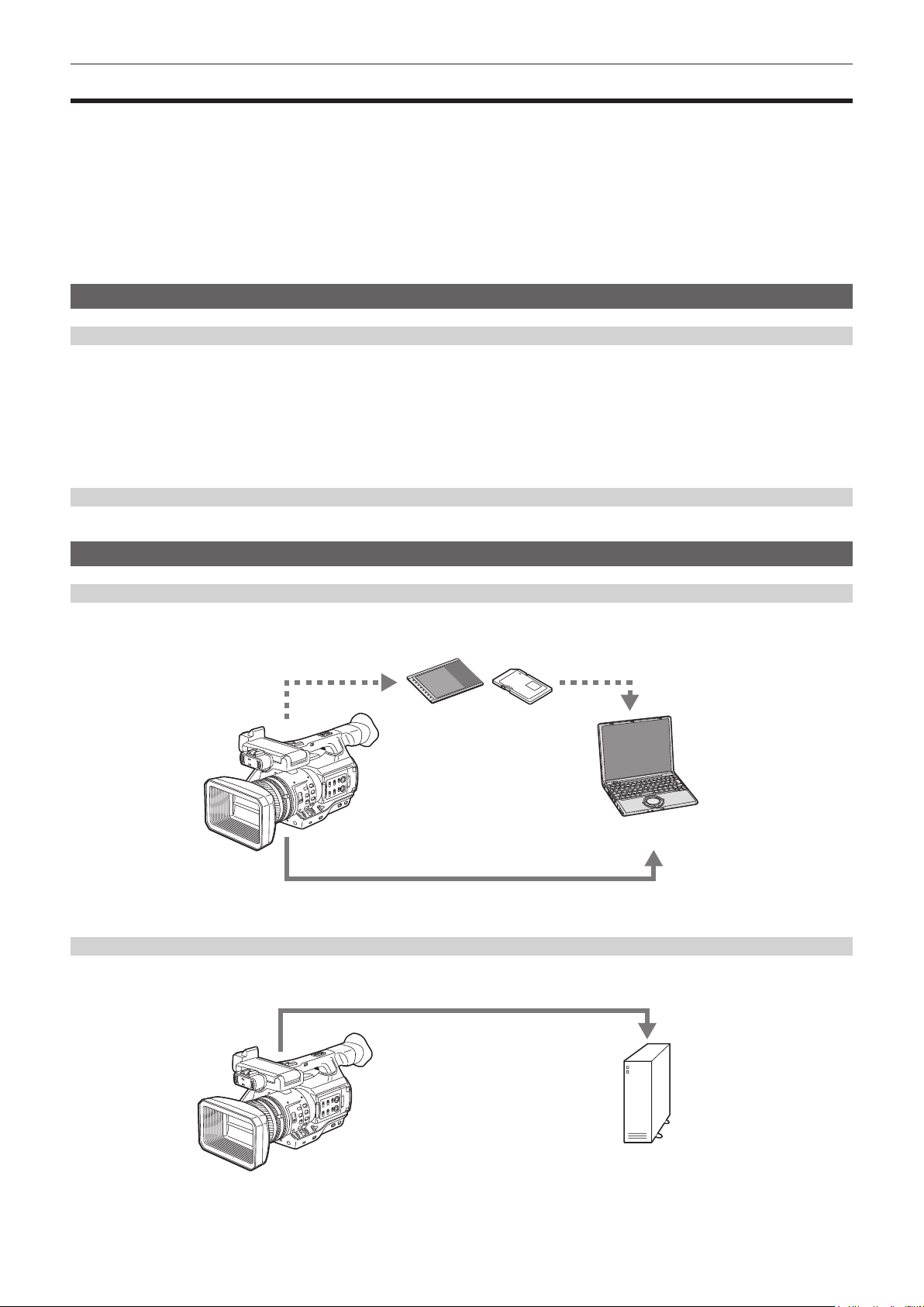
Linking to external devices
USB device mode
Data (les) for performing nonlinear editing on a computer are transferred.
P2 memory card, microP2 memory card*
USB 2.0 (device mode)*
*1 P2 memory cards and microP2 memory cards are optionally available. They are not supplied with the camera.
*2 The USB 2.0 cable is not supplied with the camera. Prepare a commercial USB 2.0 cable (double-shielded for noise suppression).
2
USB host mode (<USB3.0 HOST> terminal connection)
The camera directly controls the hard disk drive to transfer data.
USB 3.0*
1
Personal computer
External storage device
* A USB 3.0 cable is not supplied with this product. Use a commercially sold USB 3.0 cable (with double shielding for noise reduction).
– 14 –
Page 15
Chapter 1 Overview — What you can do with this camera
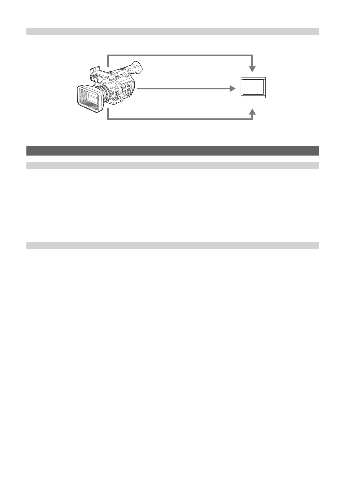
Connecting to monitor
A monitor can be connected to output images.
Audio pin cable*
1
HDMI cable*
2
Monitor
BNC cable (composite/HD SDI/SD SDI)*
*1 Cables are optionally available. They are not supplied with the camera.
*2 Use an HDMI cable (optional) with double shielding. For the HDMI cable, using Panasonic HDMI cable is recommended.
*3 For the BNC cable (optional) connected to the <SDI OUT> terminal, prepare a double-shielded cable equivalent to 5C-FB.
3
Connecting to the network
Wired LAN connection
The following operations are available on your computer via LAN terminal:
f Camera status check
f Thumbnail image check
f Proxy playback*
f Download of proxy le/clip management information
f Displaying/editing of metadata
f Adding/deleting of metadata (shot mark or text memo)
f Camera remote control (collective operations of recording control and time code/user bits)
In addition, clip transferring can be performed by the FTP client function via the LAN terminal.
* Contents which were recorded with AVC-LongG 6 cannot be played back.
Connecting using wireless LAN connection and 4G adaptor*
Attaching the wireless module AJ-WM30 (optional) to the <USB2.0 HOST> terminal (sub-host) of the camera allows you to connect the camera via
wireless LAN (IEEE 802.11).
The following operations are available using your tablet, smartphone, and computer.
f Camera status check
f Thumbnail image check
f Proxy playback
f Displaying/editing of metadata
f Adding/deleting of metadata (shot mark or text memo)
f Camera remote control (collective operations of recording control and time code/user bits)
In addition, clip transferring can be performed by the FTP client function via wireless LAN (access point connection) or 4G adaptor*.
* Schedule to support when future versions are upgraded
– 15 –
Page 16

Chapter 2 Description of Parts
This chapter describes the names, functions, and operations of parts on the camera.
Page 17
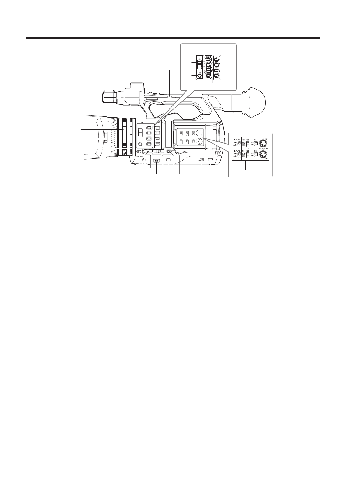
Left side
Chapter 2 Description of Parts — Left side
20 21
22
23
26 27
2524
28
29
30
31
1
2
3
4
5
7 9 11 13 14
6 8
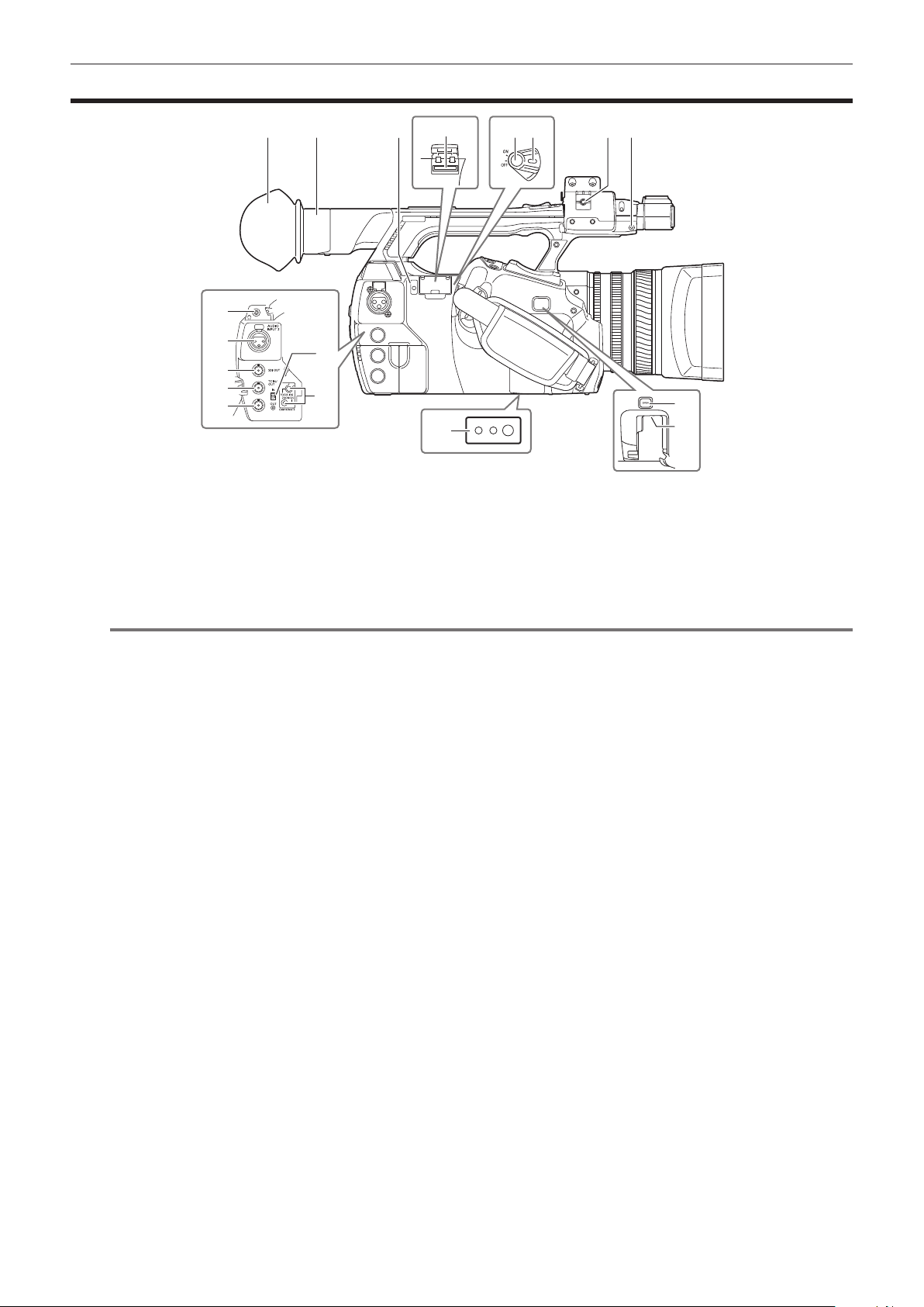
1 Focus ring (page 47)
Focus manually when the <FOCUS> switch is set to <M>.
2 Zoom ring (page 54)
Adjust the zoom manually when the <ZOOM> switch is set to <MANUAL>.
3 Lens cover switching lever (page 30)
Open/close the lens cover.
4 Iris ring (page 47)
Adjust the lens iris manually when the manual iris is set with the <IRIS> button.
5 <ZOOM> switch (page 54)
Select the operation of the zoom.
<SERVO>: You can use the motor-driven zoom using the zoom lever.
<MANUAL>: You can operate the zoom ring manually to adjust the angle of view.
6 <DISP/MODE CHK> switch (page 72)
This is the spring switch to check the status of the shooting, etc.
f Push this switch towards the <OFF> side to clear all displays except the display of the operation status, frame display such as an area, counter,
marker, and safety zone.
f Push this switch towards the <CHK> side to display all information such as setting status of the functions for the shooting, the list of functions
assigned to the USER buttons on the LCD monitor during shooting stand-by or shooting. Each time the switch is pushed towards the <CHK> side,
the display of the status switches in turn.
7 <GAIN> switch (page 47)
Switch the brightness of the screen according to the lighting conditions under which you are shooting.
8 <F.AUDIO LEVEL> dial (page 64)
In the following conditions, the recording levels for the audio channels 1 to 4 can be adjusted.
f When the <CH1>/<CH2> switch is set to <MANU>
f When [AUTO LEVEL CH3]/[AUTO LEVEL CH4] is set to [OFF] in the main menu → [AUDIO SETUP] → [RECORDING CH SETTING]
Assignment of audio channels 1 to 4 can be performed in the main menu → [AUDIO SETUP] → [RECORDING CH SETTING] → [FRONT VR
SELECT].
9 <WHITE BAL> switch (page 51)
Select the method for adjustment of the white balance.
<PRST>: Set the white balance to the preset value. Each time the <AWB> button is pressed, [3200K], [5600K], and [VAR] are toggled.
<A>/<B>: Select when using the stored value of the adjustment of the white balance.
10 <MENU> button (page 116)
Press this button to display [USER MENU]. Press this button for 3 seconds or more to display the main menu. Press it again to return to the original
image.
11 <SEL/PUSH SET> dial button (page 116)
Move, select, and set the items in the setting menu while the setting menu is displayed.
Set the preset values of the shutter, synchro scan, variable frame rate value, and white balance.
12 <MODE/MENU CANCEL> button (page 59)
f When the setting menu is not displayed, each press of the button switches modes to change the variable value of shutter speed, variable frame
rate, and white balance.
f When the setting menu is displayed, setting of the menu items is canceled and the previous screen is displayed.
10 12
15
16 18
17 19
– 17 –
Page 18

Chapter 2 Description of Parts — Left side
13 <AUTO/MANUAL> switch
Select the method to adjust the focus, gain, iris, white balance, and shutter speed at shooting. You can set the function to assign to <AUTO> in the
main menu → [AUTO SW].
<AUTO>: Adjust automatically. (Auto mode)
<MANUAL>: Adjust manually. (Manual mode)
14 <SLOT SEL> button
Select the microP2 memory card slot for the target of recording.
This button can be used as the USER button (USER7). (page 38)
15 Diopter adjustment lever (page 41)
Adjust the diopter scale so that the viewnder screen can be viewed clearly.
16 <INPUT 1>/<INPUT 2> switch (page 63)
Switch audio input signals connected to the <AUDIO INPUT 1>/<AUDIO INPUT 2> terminal.
<LINE>: Select when audio equipment is connected by the line input.
<MIC>: Select when the external microphone is connected.
<+48V>: Select when the external microphone is connected and the microphone needs power supply.
17 <CH1 SELECT>/<CH2 SELECT> switch (page 63)
Select the audio to be recorded to audio channel 1/2.
<INT(L)>/<INT(R)>: Record left audio (right audio) of the built-in microphone.
<INPUT1>: Record input signals from the <AUDIO INPUT 1> terminal.
<INPUT2>: Record input signals from the <AUDIO INPUT 2> terminal.
18 <CH1>/<CH2> switch (page 64)
Select the method to adjust the input level of audio channel 1/2.
<AUTO>: Adjust automatically.
<MANU>: Adjust using the <AUDIO LEVEL CH1>/<AUDIO LEVEL CH2> dial.
19 <AUDIO LEVEL CH1>/<AUDIO LEVEL CH2> dial (page 64)
Adjust the recording level of audio channel 1/2.
20 Internal speaker
Output audio during playback.
When connecting the headphones to the headphones terminal, audio from the speaker turns off automatically.
21 HANDLE ZOOM switch (page 54)
Select the operation of the zoom lever (handle side).
<FIX>: Zoom in/out with the speed set in the main menu → [SW MODE] → [H.ZOOM SPEED].
<VAR>: Zoom speed changes depending on how strong the lever is pushed. (When pushed gently, the speed becomes slower, and when pushed
strongly, it becomes faster.)
<OFF>: The zoom lever does not work.
22 <ND FILTER> switch (page 47)
Select the lter to suit the illumination of the subject.
<1/64>: Reduce the amount of light entering the MOS sensor to 1/64.
<1/16>: Reduce the amount of light entering the MOS sensor to 1/16.
<1/4>: Reduce the amount of light entering the MOS sensor to 1/4.
<OFF>: Does not use the ND lter.
23 <IRIS> button (page 47)
Select the method for adjustment of the lens iris.
24 <FOCUS ASSIST> button (page 48)
Switch on/off the focus assist function.
This button can be used as the USER button (USER1). (page 38)
25 <MACRO> button (page 47)
Switch on/off the macro function of the focus.
This button can be used as the USER button (USER2). (page 38)
26 <FOCUS> switch (page 47)
Select the focus function.
<A>: Changes to the auto focus mode. Adjust the focus automatically.
<M>: Changes to the manual focus mode. Control the focus ring manually to adjust the focus.
<c>: Changes to the manual focus mode after the focus distance is set to innity.
This is the spring switch. Even when the <FOCUS> switch is pushed towards the <c> side, the switch returns to the <M> position.
27 <PUSH AUTO> button (page 48)
When the button is pressed in manual focus mode, focus is adjusted automatically while it is pressed.
28 <OIS> button (page 72)
Switch on/off the image stabilization function.
This button can be used as the USER button (USER3). (page 38)
29 <ZEBRA> button (page 71)
Select the display of either zebra of marker.
This button can be used as the USER button (USER4). (page 38)
30 <WFM> button (page 73)
Select whether to display the waveform monitor on the LCD monitor.
This button can be used as the USER button (USER5). (page 38)
31 <A.IRIS.LEVEL> button
Switch on/off the auto iris function.
Set the target value of the auto iris level in the main menu → [SCENE FILE] → [A.IRIS LEVEL EFFECT].
This button can be used as the USER button (USER6). (page 38)
– 18 –
Page 19
Right side
Chapter 2 Description of Parts — Right side
1
9
10
11
12
13
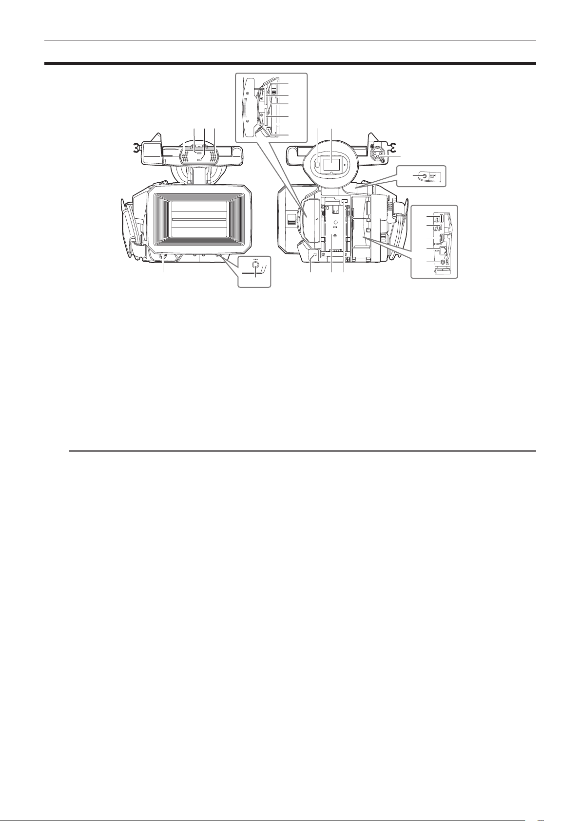
1 Eye cup (page 30)
2 Eye piece
3 Busy (active status indication) lamp (page 84)
Indicate the active status of the SD memory card, and is illuminated when the card is active.
4 SD memory card slot (page 84)
This is the insertion slot for the SD memory card (optional). Use the SD memory card for recording/opening the setting menu of the camera, or
uploading metadata or proxy recording, etc.
NOTE
@@
t Cautions when using SD memory cards
- On the camera, use SD memory cards that conform to the SD standard, SDHC standard, or the SDXC standard. When performing proxy
recording, use SDHC memory cards, SDXC memory cards, or SD memory cards with the class description of class2 or higher.
- MMC (Multi Media Card) cannot be used. (Bear in mind that taking pictures may no longer be possible if you use them.)
- When using miniSD/microSD cards with the camera, always install the adaptor specially designed for miniSD/microSD cards. (The camera will
not work properly if only the miniSD/microSD adaptor is installed. Make sure that the card has been inserted into the adaptor before use.)
- Use of Panasonic SD memory cards and miniSD/microSD cards is recommended. Be sure to format cards on the camera before use.
- Refer to our support desk at the following website for the latest information not included in these operating instructions.
http://pro-av.panasonic.net/
- SDHC memory cards are a standard that was established in 2006 by the SD Association for large-capacity memory cards that exceed 2 GB.
- SDXC memory cards are a standard that was established in 2009 by the SD Association for large-capacity memory cards that exceed 32 GB.
5 Recording button (grip side) (page 44)
Press this button to start recording. Press it again to stop recording.
Used for direct shooting in thumbnail mode.
6 Power switch (page 44)
Switch on/off the power.
7 Microphone cable clamp (page 31)
Used for securing the microphone cable.
8 Pin holder
Attach the zoom ring pin which is removed from the camera.
9 Headphones terminal (page 150)
This is the connecting terminal of headphones for audio monitor.
10 <AUDIO INPUT 2> terminal (XLR, 3-pin) (page 63)
Connect the audio equipment or the microphone.
11 <SDI OUT> terminal (page 96)
This is the output terminal for HD/SD SDI signals.
12 <TC IN/OUT> terminal (page 89)
This is the input/output terminal for time code.
Use the <IN/OUT> switch to select the input or output.
13 <GENLOCK IN/VIDEO OUT> terminal (page 94)
This is the input terminal for reference signals when setting the genlock to the camera section. This is the output terminal of the video for monitor.
Use the <IN/OUT> switch to switch the input or output.
14 <IN/OUT> switch (page 92)
Switch the input and output of the <TC IN/OUT> terminal and <GENLOCK IN/VIDEO OUT> terminal.
2 3
14
15
16
54 6
87
17
18
– 19 –
Page 20

Chapter 2 Description of Parts — Right side
15 <CAM REMOTE> terminal (page 150)
Connect the remote control (optional) to control some functions remotely.
<FOCUS IRIS>: (3.5 mm mini jack) Control the focus operation and iris operation remotely.
<ZOOM S/S>: (2.5 mm mini jack) Control the zoom operation and start/stop operation of recording remotely.
16 Tripod holes
Attach the tripod. (bottom)
f Mounting hole size
- 1/4-20 UNC (screw length 5.5 mm or shorter)
- 3/8-16 UNC (screw length 5.5 mm or shorter)
17 <OPEN> button (page 163)
Use this button when opening the cover of the <USB2.0 HOST> terminal at the bottom of the button.
18 <USB2.0 HOST> terminal (sub-host) (page 163)
This is the terminal for the wireless LAN. Mount the wireless module AJ-WM30 (optional).
– 20 –
Page 21
Chapter 2 Description of Parts — Front side, rear side
Front side, rear side
12
13
14
1 1
2 3
4
1 Built-in microphone (page 63)
This is the built-in stereo microphone.
2 Light sensor
Detects indoor and outdoor light.
3 Front tally lamp (page 42)
Lights during shooting. This lamp will blink when the battery level becomes low.
4 Recording button (front side) (page 44)
Press this button to start recording. Press it again to stop recording.
The operation of this button can be forbidden by the main menu → [SW MODE] → [FRONT REC].
5 <AWB> button (page 51)
Press this button to adjust the white balance. Press it for two seconds or more to adjust the white balance and then black balance.
6 Eye sensor (page 41)
Bring your eyes closer to display the screen on the viewnder.
NOTE
@@
t The eye sensor may not work properly depending on the shape of glasses in use, how you hold the camera, or by hitting the strong light around
the eye piece.
t The eye sensor does not work during video playback.
7 Viewnder (page 41)
8 <AUDIO INPUT 1> terminal (XLR, 3-pin) (page 31)
Connect the audio equipment or the microphone.
9 Rear tally lamp (page 42)
Light during shooting. This lamp will blink when the battery level becomes low.
10 Battery attachment (page 27)
11 Battery release button (page 27)
Remove the battery.
12 microP2 memory card 1 access LED (page 35)
Indicate the access status of recording and playback of the card inserted in the microP2 memory card slot 1.
13 microP2 memory card slot 1 (page 34)
14 microP2 memory card 2 access LED (page 35)
Indicate the access status of recording and playback of the card inserted in the microP2 memory card slot 2.
15 microP2 memory card slot 2 (page 34)
16 P2 memory card slot (page 34)
17 P2 memory card access LED (page 35)
Indicate the access status of recording and playback of the card inserted in the P2 memory card slot.
18 <AUDIO OUT> terminal (page 150)
Output audio signals recorded to audio channel 1/2.
19 <USB3.0 HOST> terminal (host) (page 152)
Connect external hard disk drive, etc.
20 <USB2.0 DEVICE> terminal (device) (page 152)
Connect to a computer with the USB 2.0 cable to transfer data.
21 <HDMI OUT> (monitor output) terminal (page 150)
This is the output terminal of the video for monitor.
5
15
16
17
76
8
18
19
20
21
22
23
11109
– 21 –
Page 22

Chapter 2 Description of Parts — Front side, rear side
22 <LAN> terminal (page 164)
Connect the LAN cable.
23 <DC IN 12V> terminal (page 27)
This is the input terminal for the external power supply. Connect the supplied AC adaptor.
– 22 –
Page 23
Top side
Chapter 2 Description of Parts — Top side
14 15 16
19
20
18
6
22
23
24
21
1
7
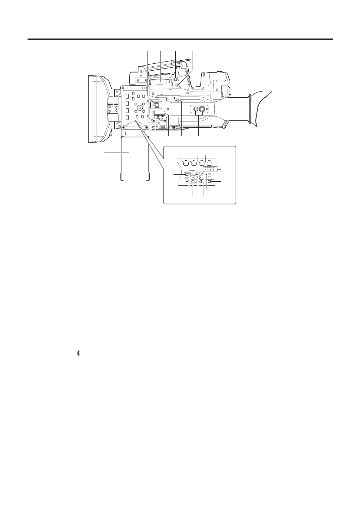
1 Light shoe
Attach the video light.
2 Recording button (handle side) (page 44)
Press this button to start recording. Press it again to stop recording.
This includes hold mechanism.
3 Zoom lever (grip side) (page 54)
Adjust the zoom of an image.
<T>: Zoom in the image.
<W>: Zoom out the image.
4 <IRIS> button (page 47)
Select the method for adjustment of the lens iris.
This button can be used as the USER button (USER8). (page 38)
5 <REC CHECK> button (page 44)
Press this button while recording is suspended, to play back the video and audio of the most recent clip for approximately three seconds.
6 Shoulder strap attachment (page 29)
Attach the shoulder strap.
7 LCD monitor (page 40)
8 Zoom lever (handle side) (page 54)
Adjust the zoom of an image.
<T>: Zoom in the image.
<W>: Zoom out the image.
9 Focal plane index <
Indicate the focal plane of the MOS sensor.
It provides a reference for measuring the accurate focal distance from the subject.
10 Handle mounting holes
Mount the handle.
f Mounting hole size
- 1/4-20 UNC (screw length 5.5 mm or shorter)
- 3/8-16 UNC (screw length 5.5 mm or shorter)
11 <COUNTER> button (page 93)
Switch the display item of the counter.
12 <RESET> button
Reset the display of the time counter.
13 <%> button
This works when the thumbnail screen is displayed.
Press this button during a pause to perform fast-reverse playback.
Press this button during playback to perform 4x speed reverse playback.
If it is pressed with playback paused, the clip being played back is paused at its start point (cued state).
>
2 53
6 109
4
8
13
11
12
17
– 23 –
Page 24

Chapter 2 Description of Parts — Top side
14 <(> button
This works when the thumbnail screen is displayed.
Press this button to stop playback.
Press this button when you stop interval recording or one-shot recording, or when you end combining to the clip of one-clip recording.
15 <)> button
This works when the thumbnail screen is displayed.
Press this button during a pause to perform fast playback.
Press this button during playback to perform 4x speed playback.
If it is pressed with playback paused, the clip being played back is paused at the start point of the next clip (cued state).
16 <=/&> button
This works when the thumbnail screen is displayed.
Press this button to view playback image.
Press it during playback to pause playback.
17 <THUMBNAIL> button (page 100)
Press the button to display the thumbnail screen on the LCD monitor and viewnder. Press it again to return to the regular display.
18 <EXIT>/<CANCEL> buttons (page 102)
Restore the display to the previous state while the setting menu or property screen is displayed.
Press this button while holding down the <SHIFT> button to act as the cancel button. This is convenient, for example, for batch-canceling clip
selections.
19 Control stick (page 102)
Use this button to select a thumbnail or to perform operations of menus and area mode function.
20 <MENU> button (page 116)
Press this button to display [USER MENU]. Press this button for 3 seconds or more to display the main menu.
Press it while the thumbnail is displayed to display the operation screen of the thumbnail menu, and clips can be deleted.
21 <SHIFT> button (page 102)
Use this button together with the control stick or other buttons.
f Press the control stick upward/downward while holding down the <SHIFT> button.
This moves the cursor to the thumbnail of the clip at the start or the end on the thumbnail screen.
f Press the control stick while holding down the <SHIFT> button.
This selects all clips from the previously selected clip up to the clip at the cursor position.
f Press the <EXIT>/<CANCEL> buttons while holding down the <SHIFT> button.
This works as the cancelation function. (page 24)
Operations with the <SHIFT> button held down are displayed in orange at each operation section.
22 <AUDIO MON/ADV> button (page 99)
<+>: When pressing during playback, the audio volume of the monitor is increased. When pressing during pause, frame-by-frame play is performed.
<−>: When pressing during playback, the audio volume of the monitor is decreased. When pressing during pause, frame-by-frame rewind is
performed.
23 <BARS> button (page 72)
Switch on/off the color bar. The color bar is interlocked with the test tone (1 kHz).
24 <LCD BACKLIGHT> button (page 40)
Select the brightness of the backlight of the LCD monitor.
– 24 –
Page 25

Chapter 3 Preparation
Before you use the camera, mount the battery following the procedures in this chapter. The mounting of accessories is also described in this chapter.
Page 26
Chapter 3 Preparation — Power supply
Power supply
A battery or AC adaptor can be used as the power supply.
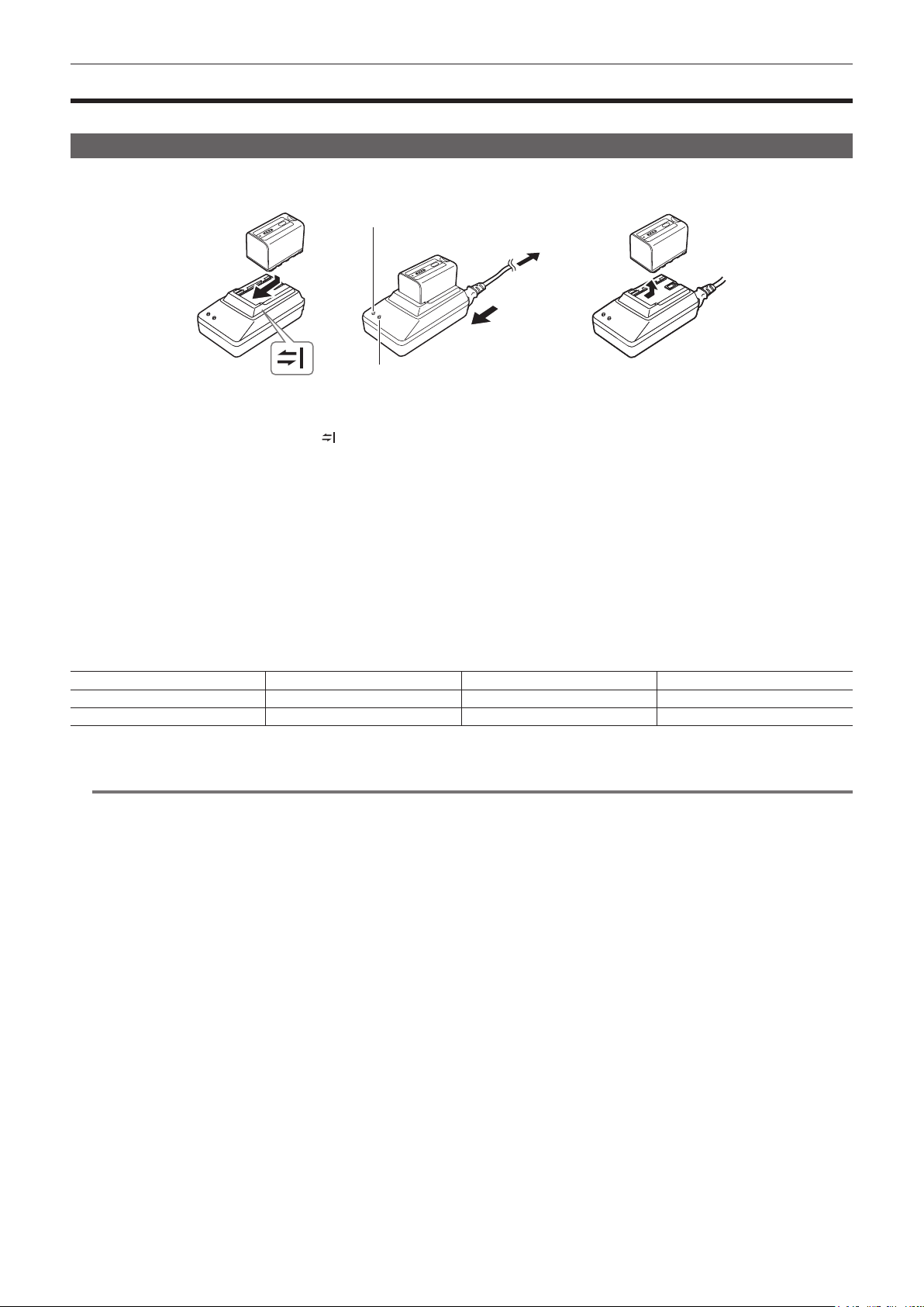
Charging the battery
The battery is not charged at the time of purchase. Fully charge the battery in the battery charger before using the battery.
It is recommended that you have one extra battery.
<POWER> lamp
To the power outlet
(2)
(1)
<CHARGE> lamp
Fig. 1 Fig. 2 Fig. 3
Place the battery horizontally along the mark in the battery charger and slide it in. (Fig. 1)
1
Press it in rmly.
Connect an AC cable. (Fig. 2)
2
Connect in the order shown in the gure.
f <POWER> lamp
- Once the AC cable is connected, the lamp will light up.
f <CHARGE> lamp
- Lit: Charging.
- Not lit: Charging is complete.
- Flashing: Reinsert the battery.
Slide the battery out to remove it. (Fig. 3)
3
r Standard charging time and recording time
Battery parts number Voltage/capacity Charging time Continuous shootable time
VW-VBD58 (supplied) 7.2 V/5800 mAh Approx. 380 min Approx. 90 min
CGA-D54/CGA-D54s (optional) 7.2 V/5400 mAh Approx. 330 min Approx. 85 min
f The time when the ambient operating temperature is 20°C (68°F) and the relative operating humidity is 60%. At other temperature and humidity the
charging time may take longer.
NOTE
@@
t Continuous recordable time is applied under the following conditions. If you use the camera in other conditions, continuous shootable time will shorten.
- With the LCD monitor open
- When the main menu → [OUTPUT SEL] → [SDI OUT] is set to [OFF]
- When the main menu → [OUTPUT SEL] → [VIDEO OUT] is set to [OFF]
- With the cable not inserted into the <HDMI OUT> terminal
t The battery and camera recorder will become warm during use or while charging.
t Make sure that batteries are discharged before storing them.
t When stored for long periods of time, it is recommended that you charge batteries once per year and then use up the battery capacity by using the
battery in the camera recorder before storing it again.
t When the battery becomes extremely hot or cold, the <CHARGE> lamp will ash several times and charging will automatically begin.
t When the battery is left unused and discharged for a long time, the <CHARGE> lamp will ash several times and charging will automatically begin.
t If the <CHARGE> lamp continues blinking even when the battery is at its optimal temperature, the battery or battery charger may be damaged.
Contact a dealer.
t If the battery is warm, it will take longer than usual to charge.
t If you use the battery charger near a radio, the radio sound may be distorted. Keep the battery and battery charger at least 1 m away from radios
when in use.
t Noise may be emitted from the battery charger when using the battery charger, but this does not indicate a malfunction.
r Supplied battery
f Remaining battery level display function
The approximate remaining battery level can be checked by looking at the LED display of the battery.
The displayed battery level may be different when the battery is attached to the camera and you are shooting and when the battery is not attached.
f The supplied battery is intended for use only in this camera.
Do not use it in other devices.
– 26 –
Page 27
Attaching and removing the battery
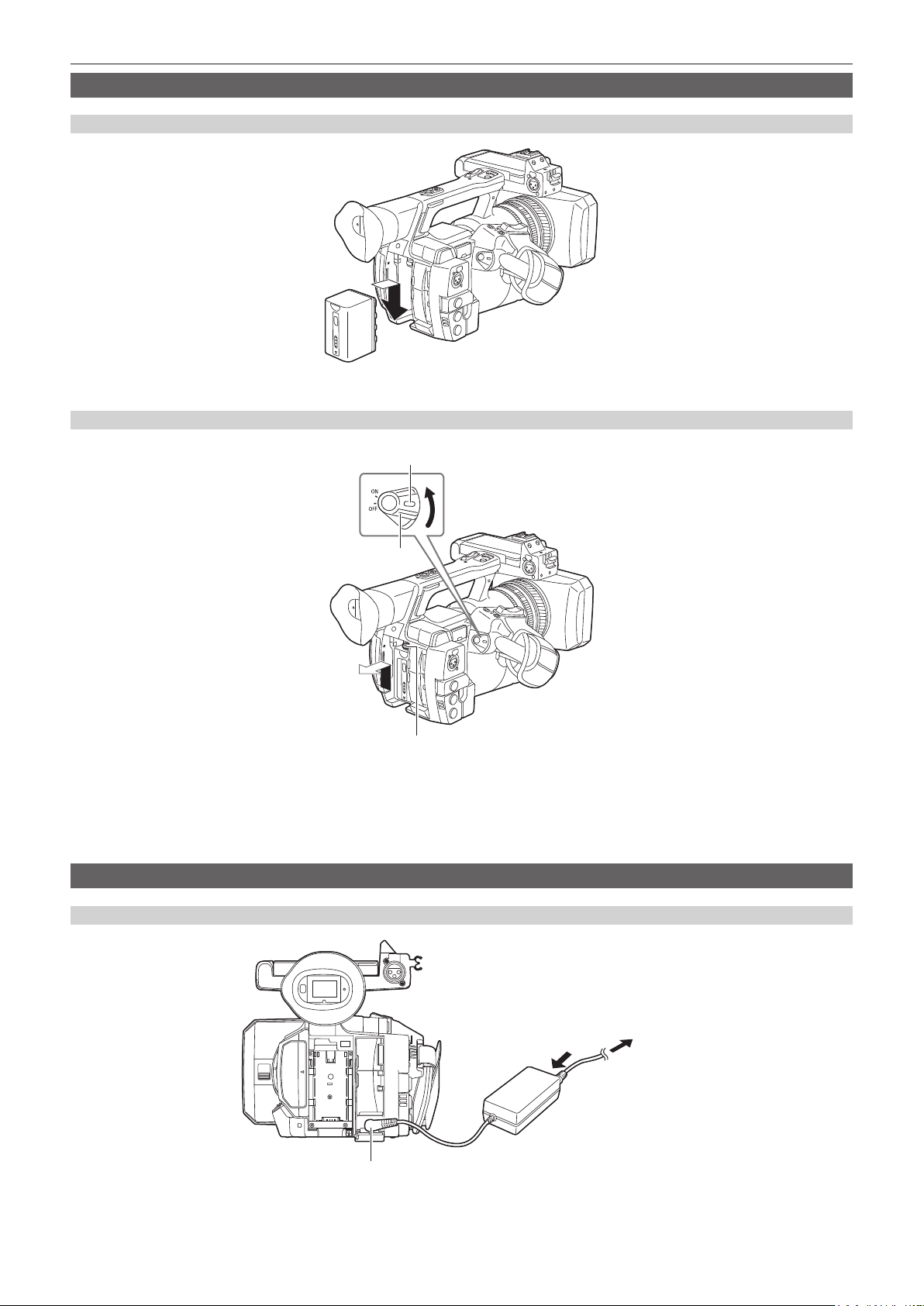
Attaching
Insert the battery until you hear it clicks.
1
Removing
Chapter 3 Preparation — Power supply
Lock release button
Power switch
Battery release button
Turn the power switch to <OFF> while holding down the lock release button.
1
Make sure that the LCD monitor has gone off.
Lift up and remove the battery while holding down the battery release button.
2
Support the battery with your hand so that it does not fall down.
Using the AC adaptor
Attaching
Connect an AC cable.
1
Connect in the order shown in the gure.
<DC IN 12V> terminal
– 27 –
To the power outlet
(1)
(2)
Page 28

Chapter 3 Preparation — Power supply
Connect the AC adaptor to the <DC IN 12V> terminal.
2
Removing
Turn the power switch to <OFF> while holding down the lock release button.
1
Make sure that the LCD monitor has gone off.
Remove the AC adaptor from the <DC IN 12V> terminal.
2
NOTE
@@
t When not using the camera, remove the AC cable from the power outlet.
t Use the supplied AC adaptor. Do not use other AC adaptors.
t The AC adaptor can be connected when attaching the battery to the camera. When the AC adaptor is connected, the camera will switch to be powered
by the AC adaptor. When removing the AC adaptor, the camera will be powered by the battery.
– 28 –
Page 29
Chapter 3 Preparation — Attaching and adjusting accessories
Attaching and adjusting accessories
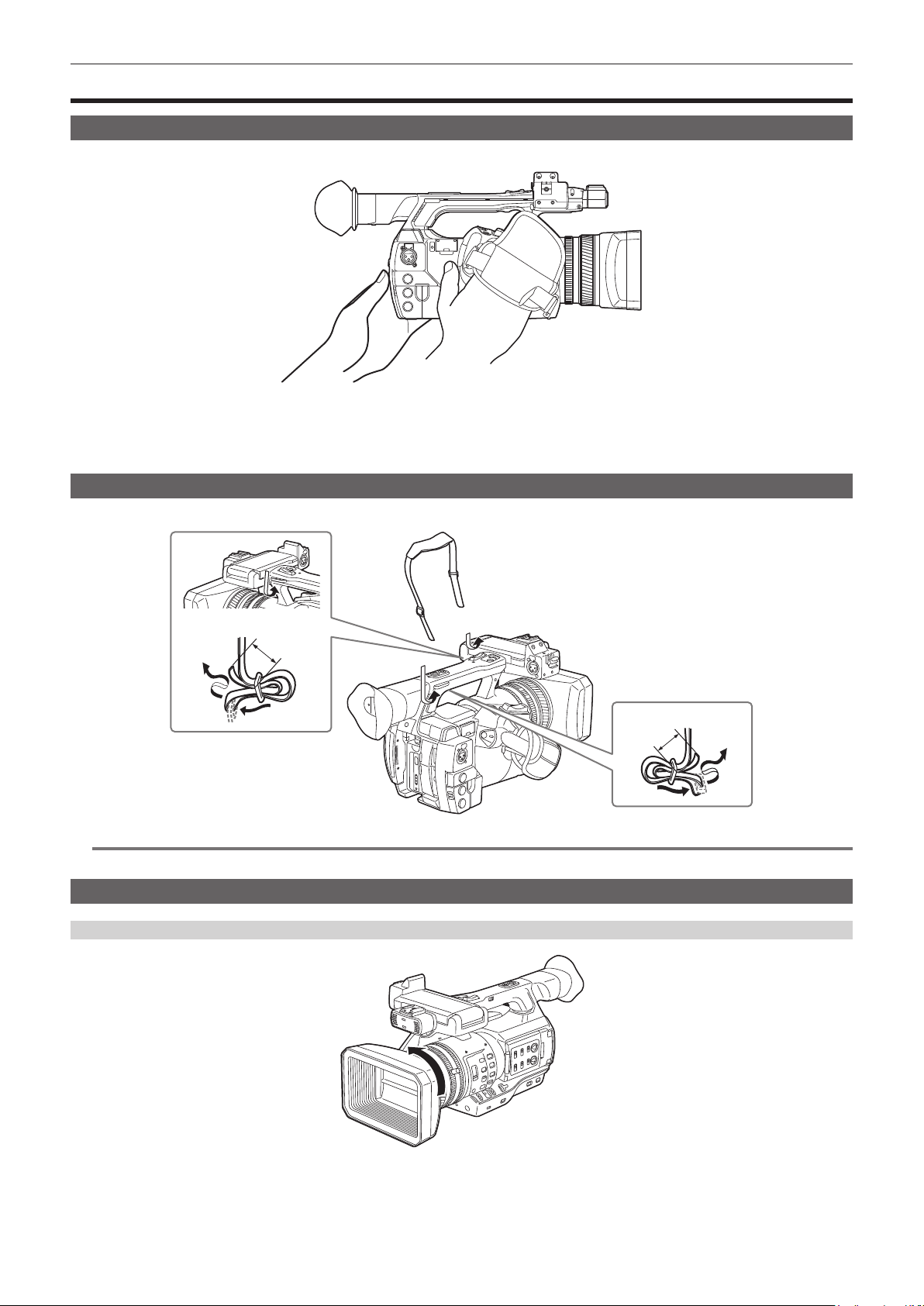
Adjusting the grip strap
Adjust the grip strap so that it ts the size of your hand.
Open the cover and adjust the length of the strap.
1
Replace the cover.
2
Attach the cover rmly.
Attaching the shoulder strap
Attach the shoulder strap to the attachment lugs.
Longer than 20 mm
NOTE
@@
t Make sure that the shoulder strap is securely attached.
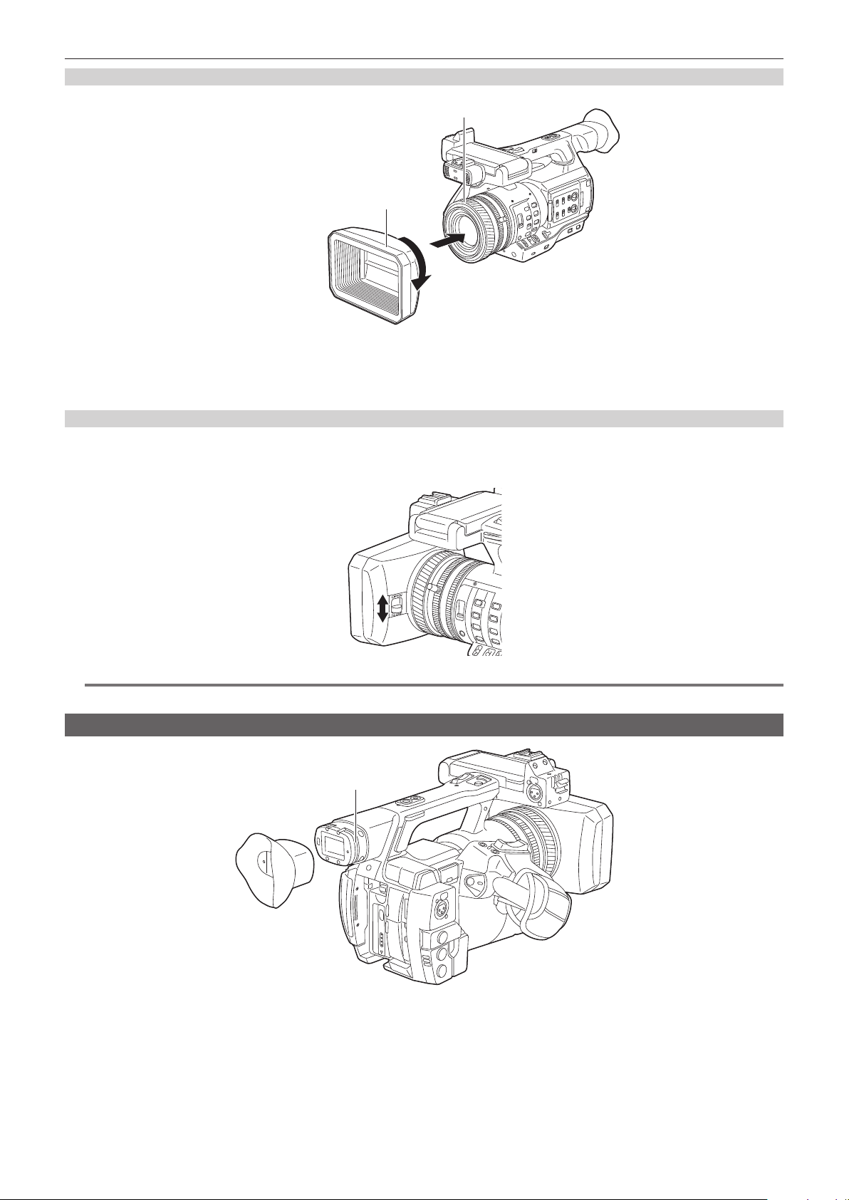
Attaching the lens hood
Removing
Longer than 20 mm
Rotate the lens hood counter-clockwise.
1
– 29 –
Page 30
Chapter 3 Preparation — Attaching and adjusting accessories
Attaching
Center of camera
The side with the index of the lens hood
Align the index of the lens hood with the center of the camera body and attach.
1
Position the lens hood so that the side with the index of the lens hood is facing upwards.
Rotate the lens hood clockwise until it locks in with a click.
2
Opening and closing the lens cover
Use the lens cover open/close lever to open and close the lens cover.
Open the lens cover to take videos and photographs.
When not using the camera, close the lens cover in order to protect the lens.
NOTE
@@
t Do not press the lens cover with force. Doing so may damage the lens and lens cover.
Attaching the eye cup
Groove
Attach the eye cup by aligning the groove on the attaching part of the eye cup with the inner ridge of the eye cup.
1
– 30 –
Page 31

Chapter 3 Preparation — Attaching and adjusting accessories
Attaching the front microphone
Microphones such as a super-directional microphone AG-MC200G (optional) can be attached.
Screws for tapped hole protection are attached on the camera body. Remove those screws when you attach the microphone holder.
Screw for the microphone holder
Microphone cable clamp
Microphone holder
<AUDIO INPUT 1> terminal
Fig. 3Fig. 2Fig. 1
Attach the microphone holder. (Fig. 1)
1
Attach the microphone and tighten the microphone holder clamping screw. (Fig. 2)
2
Connect the microphone connecting cable to the <AUDIO INPUT 1> terminal on the camera. (Fig. 3)
3
Secure the microphone connecting cable with the microphone cable clamp.
4
Set the <INPUT 1> switch to match the microphone to be connected.
5
NOTE
@@
t The microphone holder cannot be xed with the screws originally attached on the camera. Use the dedicated screws that came with the camera to x
the microphone holder.
Attaching a tripod
The tripod attachment holes accept 1/4-20 UNC and 3/8-16 UNC screws. Use the hole that matches the diameter of the clamping screw on the tripod.
NOTE
@@
t Use a tripod in safe locations.
t The depth of the tripod attachment hole is 5.5 mm. When attaching the camera to a tripod, do not over-tighten the tripod screw.
– 31 –
Page 32

Chapter 3 Preparation — Turning on/off the power
Turning on/off the power
How to turn on the power
Align the power switch to <ON> while holding down the lock release button.
1
The LCD monitor lights up.
How to turn off the power
Align the power switch to <OFF> while holding down the lock release button.
1
The LCD monitor goes off.
Lock release button
Power switch
– 32 –
Page 33

Chapter 3 Preparation — Setting the date/time of the internal clock
Setting the date/time of the internal clock
The value of the time is recorded to content (clips) and affects the thumbnail playback order. Before recording, be sure to check and set the date and
time zone.
Press the <MENU> button for 3 seconds or more.
1
f The main menu screen is displayed in the viewnder and on the LCD monitor.
Select the main menu → [OTHER FUNCTIONS] → [CLOCK SETTING] to set the year, month, day, and time.
2
For details on the settings menu, refer to “Setting menu basic operations” (page 116).
Select the main menu → [OTHER FUNCTIONS] → [TIME ZONE] to set the time difference from Greenwich Mean Time.
3
NOTE
@@
t You can correct the date and time of the internal clock from GPS by enabling the GPS function.
r Time zone table
Time difference Region Time difference Region
00:00 Greenwich
−00:30 +01:30
Azores
−01:00
−01:30 +02:30
Mid-Atlantic
−02:00
−02:30 +03:30
Buenos Aires
−03:00
Newfoundland
−03:30
Halifax
−04:00
−04:30 +05:30
New York
−05:00
−05:30 +06:30
Chicago
−06:00
−06:30 +07:30
Denver
−07:00
−07:30 +08:30
Los Angeles
−08:00
−08:30 +09:30
Alaska
−09:00
Marquesas Islands
−09:30
Hawaii
−10:00
−10:30 +11:30
Midway Islands
−11:00
−11:30 +12:45
Kwajalein Atoll
−12:00
+00:30
+01:00
+02:00
+03:00
+04:00
+04:30
+05:00
+06:00
+07:00
+08:00
+09:00
+10:00
+10:30
+11:00
+12:00
+13:00
Central Europe
Eastern Europe
Moscow
Tehran
Abu Dhabi
Kabul
Islamabad
Bombay
Dakar
Yangon
Bangkok
Beijing
Tokyo
Darwin
Guam
Lord Howe Island
Solomon Islands
Norfolk Island
New Zealand
Chatham Islands
NOTE
@@
t Be sure to make this setting before using the camera for the rst time. After, do not change the setting during use.
t Clock accuracy is a lunar inequality of approximately ±30 seconds with the power off. When accurate time is required, check and reset the time when
the power is turned on.
t The built-in clock runs for several years on the built-in lithium cell of the camera. When the lithium cell runs low,
and LCD monitor screen when the camera is turned on. For details, refer to “Maintenance” (page 175).
will be displayed in the viewnder
– 33 –
Page 34

Chapter 3 Preparation — P2 card
P2 card
Inserting a P2 card
When using the camera for the rst time, be sure to set the time data beforehand. (page 33)
Select and use either of the microP2 or P2 memory card slot on the camera.
microP2 memory card slot 1
Eject button
microP2 memory card access LED
Card slot cover
microP2 memory card slot 2
Fig. 1 Fig. 2 Fig. 3
Set whether to use the microP2 memory card slot or the P2 memory card slot.
1
1) Select [REC MEDIA] in the main menu → [RECORDING SETUP].
2) When using microP2 memory cards, select [microP2], and when using P2 memory cards, select [P2].
Open the card slot cover. (Fig. 1)
2
Insert a card into the card slot. (Fig. 2)
3
f microP2 memory cards
- Insert with the label side facing left.
- There are two microP2 memory card slots.
f P2 memory cards
- Insert the card with the logo facing left until the eject button pops out.
- Press the eject button that popped out to the upward.
Make sure that the P2 card access LED is lit orange or green. (Fig. 3) (page 35)
4
When two microP2 memory cards are inserted in the card slots, recording will be performed in order from the microP2 memory card with the smaller
slot number. However, regardless of the slot number, if a microP2 memory card is inserted later, that microP2 memory card will be accessed later
than the previously inserted microP2 memory cards.
f Example: When microP2 memory cards are inserted in two slots
If microP2 memory cards are inserted into two slots, the cards are used as P2 card in the order of the slot number 1 → 2. However, if you remove
the microP2 memory card from slot 1 and then insert it again, recording of the microP2 memory card will take place in order from slot 2 → 1.
The microP2 memory card number to be recorded to is maintained even if the camera is turned off. When the camera is next turned on, recording
can be continued to the same microP2 memory card as before the camera was turned off.
Close the card slot cover.
5
P2 memory card slot
P2 memory card access LED
NOTE
@@
t You can also switch the memory card to be recorded by pressing the USER button on which [REC MEDIA] is assigned.
t Be sure to close the card slot cover in order to prevent dropping, dust, and static electricity.
t Be sure to format P2 cards only on a P2 device.
t The microP2 memory card with the P2 card adaptor (AJ-P2AD1G) attached cannot be inserted into the P2 memory card slot on the camera.
t If SDHC/SDXC memory cards other than microP2 memory cards are used on the microP2 memory card slot, operation is not guaranteed.
t If a microP2 memory card is inserted slowly, [FORMAT ERROR!] or [NOT SUPPORTED!] may be displayed. In such a case, insert the card again.
– 34 –
Page 35

Chapter 3 Preparation — P2 card
Removing a P2 card
Fig. 1 Fig. 2
Open the card slot cover.
1
Remove the card.
2
f microP2 memory cards
- Press in the microP2 card further into the camera and let go.
- The microP2 memory card is released from the card slot, and the microP2 memory card can be removed.
f P2 memory cards
- Lift the eject button (Fig. 1), and press in. (Fig. 2)
NOTE
@@
t After insertion, do not remove the P2 card while it is being accessed or recognized (the P2 card access LED is ashing orange). Doing so may result
in a malfunction.
t If the P2 card is removed while being accessed, [TURN POWER OFF] is displayed on the LCD monitor screen or the viewnder screen, and the tally
lamp or other warning is displayed. Also, all P2 card access LEDs ash rapidly in orange. Turn off the power. (page 178)
t If the P2 card is removed while being accessed, clips on it may become irregular. Check the clips and restore them, if required. (page 105)
t If the P2 card being formatted is removed, formatting of the P2 card is not guaranteed. In this case, [TURN POWER OFF] is displayed on the LCD
monitor screen or the viewnder screen. Turn off the power and then back on again, and reformat the P2 card.
t If a P2 card is inserted into another slot during playback, the inserted card is not recognized and the P2 card access LED does not light. The P2 card
starts to be recognized when playback ends.
t Even if a P2 card is inserted in a vacant card slot during recording, the P2 card may not be recognized immediately in the following instance:
- Immediately after a pre-recording
- Immediately after a recording slot is switched
t The P2 card access LED can be set to continuously off in the main menu → [OTHER FUNCTIONS] → [ACCESS LED]. In this case, turn off the power
before removing the card, or after the card is inserted or after operation (recording, playback, etc.) has stopped, and wait for the charging to complete
before removing the card.
Preventing accidental erasure
In order to prevent erasing the recorded contents of the P2 card by mistake, turn the write protect switch on the P2 card to the Protect side (or the LOCK
side).
Write-protect switch Write-protect switch
NOTE
@@
t Write-protect switch can be switched while the card is being accessed (during recording or playback), but does not take effect until accessing of the
card stops.
P2 card access LEDs and status of P2 cards
P2 card access LED P2 card status Mode check display*
Is illuminated green Recording possible Reading/writing are both possible. [ACTIVE]
Is illuminated orange Recording target
Flashing orange Accessing card Reading/writing are currently being performed. [ACCESSING]
Flashing orange rapidly
The card is being
recognized.
Reading/writing are both possible. The card is currently
the recording target (including loop recording).
The P2 card is being recognized. [INFO READING]
[ACTIVE]
– 35 –
Page 36

Chapter 3 Preparation — P2 card
P2 card access LED P2 card status Mode check display*
Card full
Write protect
Flashing green slowly
Off
* Mode check is displayed on the LCD monitor screen or the viewnder screen. For details, refer to “Screen status display” (page 142).
Unrecordable card
Slot that is not recording
target
Card not supported
Illegal format
No card
Unauthenticated card
There is no free space on the P2 card. Reading only is
possible.
The write-protect switch on the P2 card is at the Protect
position. Reading only is possible.
Recording is not possible by the currently set recording
format since the SD memory card, etc. is inserted. To
record the card, change the recording format or use a
P2 card.
The card has been inserted into a different slot from the
slot ([P2] or [microP2]) that was selected in the main
menu → [RECORDING SETUP] → [REC MEDIA].
This card cannot be used on the camera. Replace the
card.
The P2 card is not properly formatted. Reformat the
card.
The P2 card is not inserted. The card is waiting to be
recognized.
This microP2 memory card cannot be authenticated.
Select the main menu → [CLIP] → [AUTHENTICATE],
and enter the password.
For details, refer to “Manual CPS authentication”
(page 112).
[FULL]
[PROTECTED]
[REC IMPOSSIBLE]
No display
[NOT SUPPORTED]
[FORMAT ERROR]
[NO CARD]
[AUTH NG]
P2 card recording time
r P2 cards supported on the camera
Optional P2 and microP2 memory cards with a capacity of 4 GB to 64 GB can be used with the camera. (As of March 2014)
NOTE
@@
t AJ-P2C002SG (2 GB) cards cannot be used.
t When AVC-Intra 100 in 1080/59.94P or 1080/50P mode is selected, you cannot record to the following P2 cards.
- P2 memory cards of R, A, or E series
t The driver installed on the camera may be required to be updated depending on the type of P2 card. (page 182)
t Refer to our support desk at the following website for the latest information not included in these operating instructions.
http://pro-av.panasonic.net/
r P2 card recording times
(Example when a 64 GB card is used)
System mode Recording format (codec) Recording time
AVC-Intra 100 Approx. 32 min
1080P
1080i, 720P
480i, 576i
AVC-LongG 25 Approx. 128 min
AVC-LongG 12 Approx. 256 min
AVC-Intra 100 Approx. 64 min
AVC-Intra 50 Approx. 128 min
AVC-LongG 50 Approx. 128 min
AVC-LongG 25 Approx. 256 min
AVC-LongG 12 Approx. 512 min
DVCPRO HD Approx. 64 min
DVCPRO50 Approx. 128 min
DVCPRO Approx. 256 min
DV Approx. 256 min
NOTE
@@
t The above table shows values for regular recording. With native recording, even longer recording times are available depending on the system mode.
t In the case of 32 GB P2 cards, the recording time becomes 1/2 of the above recording times, in the case of 16 GB P2 cards, the recording time
becomes 1/4, and in the case of 8 GB P2 cards, the recording time becomes 1/8.
t Indicated capacities include management and other area, so the space available for recording is less than the values in the table above.
Dividing clips recorded on P2 cards
If P2 cards with a capacity of 8 GB or more are used on the camera, recording is automatically continued as another clip when a single continuous
recording time exceeds the following times. When thumbnails for clips are handled (displayed, deleted, restored, etc.) on P2 devices, they can be
handled as a single clip. Clips may be displayed as separate clips in nonlinear editing software and on a computer. When recording on microP2
memory cards that exceed 32 GB in AVC-LongG codec, recording can be continued as the same clip by selecting [ONE FILE] from the main menu →
[RECORDING SETUP] → [FILE SPLIT].
Recording format (excluding native recording) Continuous recording time
AVC-I100 (1080P) Approx. 3 min
– 36 –
Page 37

Chapter 3 Preparation — P2 card
Recording format (excluding native recording) Continuous recording time
AVC-I100 (1080i)
DVCPRO HD
AVC-LongG 50
AVC-Intra 50
DVCPRO50
AVC-LongG 25
DVCPRO
DV
AVC-LongG 12 Approx. 40 min
Approx. 5 min
Approx. 10 min
Approx. 20 min
CPS (Content Protection System)
The microP2 memory card supports the security function “Content Protection System” that allows encryption formatting to prevent data leak to third
parties.
To use the CPS function, set a CPS password to the camera, and enable the microP2 memory card authentication and encryption formatting functions.
An encrypted microP2 memory card will be automatically recognized between devices where the same CPS password is set, and recording and
playback of the microP2 memory card are enabled. For details, refer to “Setting CPS password” (page 112).
NOTE
@@
t Setting or deleting of CPS can be performed in the main menu → [CLIP] → [PROPERTY] → [CPS PASSWORD].
t Up to 16 characters can be input.
t The encrypted microP2 memory card is not recognized on the SD card slot in a computer.
t If the card is unable to be recognized, authenticate with the correct password or format and use the card as recording media. Recording data on the
card failed to be recognized cannot be checked. Do not perform any operation other than manual authentication and formatting with the failed card
inserted.
t To access the encrypted card from a computer in the USB device mode, authenticate the encrypted card with P2 Viewer Plus.
How to handle data recorded on P2 cards
P2 cards are semiconductor memory cards that are used as the recording medium in the professional video production and broadcasting devices that
make up the DVCPRO P2 series.
f Since data recorded in the P2 format is in a le format, they have excellent compatibility with computers. The le structure is a unique format, which
in addition to video and audio data in MXF les contains various other important information items. The folder structure links data recorded in the P2
format as shown below.
Drive:\
CONTENTS
AVCLIP
AUDIO
CLIP
ICON
PROXY
VIDEO
VOICE
LASTCLIP.TXT*
All these folders are required.
If even part of this information is modified or deleted, the data may no longer
be recognized as P2 data, or the card may no longer be able to be used with
P2 devices.
This is the file to which the information of the final clip that was recorded
with the P2 device is written.
NOTE
@@
t P2 cards formatted on devices other than microP2 memory card compatible devices do not have the AVCLIP folder. For P2 cards without the AVCLIP
folder, the folder will automatically be created when recording is performed on microP2 memory card compatible devices.
t When transferring data from a P2 card to a computer, or when rewriting data saved on a computer back to a P2 card, to prevent data loss be sure to
download the special “P2 Viewer Plus” software. For details on downloading P2 Viewer Plus and the operating environment, visit the support desk at
the following website:
http://pro-av.panasonic.net/
t Follow the steps below to use general IT tools such as Microsoft Windows Explorer or Apple Finder to transfer the data to a computer. Be sure to use
P2 Viewer Plus to write data back to a P2 card.
- Transfer the corresponding CONTENTS folder and LASTCLIP.TXT le together as a set.
- Do not transfer individual les from the CONTENTS folder.
- When copying, copy the LASTCLIP.TXT le at the same time as the CONTENTS folder.
- When transferring the data in multiple P2 cards to a computer, create a folder for each P2 card to prevent clips with the same name from being
overwritten.
- Do not delete data from the P2 card.
- Be sure to format P2 cards on a P2 device or P2 Viewer Plus.
– 37 –
Page 38

Chapter 3 Preparation — Assigning functions to the USER buttons
Assigning functions to the USER buttons
Selected functions can be assigned to USER1 to USER8.
Set the functions to be assigned to [USER1] to [USER8] in the main menu → [USER SW].
Check the setting details using the <DISP/MODE CHK> button.
The following button functions are assigned to USER1 to USER8 as the factory settings. (The numbers of the USER buttons are displayed in the
camera.)
f USER1: <FOCUS ASSIST>
f USER2: <MACRO>
f USER3: <OIS>
f USER4: <ZEBRA>
f USER5: <WFM>
f USER6: <A.IRIS.LEVEL>
f USER7: <SLOT SEL>
f USER8: <IRIS>
USER2
USER1
USER3
USER4
USER8
USER7
USER5
USER6
Selectable functions
Item Description
[INHIBIT] Disables assignment of functions.
[SCENE FILE SEL]
[LEVEL GAUGE
RESET]
[WFM]
[D.ZOOM] Assigns the digital zoom function. Zooms in on the eld angle by 2x, 5x, and 10x vertically and horizontally.
[DRS] Assigns the dynamic range stretcher function.
[FBC] Switches the ash band compensation function to enabled/disabled.
[S.GAIN]
[1S.EXP.] Enables/disables the one second exposure function.
[ATW] Switches the auto tracking white balance functions to enabled/disabled.
[ATW LOCK]
[SPOTLIGHT] Switches the auto iris control function for the spot light to enabled/disabled.
[BACKLIGHT] Switches the auto iris control function for the backlight compensation to enabled/disabled.
[BLACKFADE] Assigns the functions that fade out the entire image as black.
[WHITEFADE] Assigns the functions that fade out the entire image as white.
[A.IRIS.LEVEL] Switches the auto iris setting function to enabled/disabled.
[IRIS] Assigns the function for switching the auto iris and manual iris.
[Y GET]
[FOCUS ASSIST] Switches the manual focus assist display to on/off.
[FOCUS MACRO]
[OIS] Switches the image stabilizer to enabled/disabled.
[FAST ZOOM] Speeds up the zoom speed when the zoom lever (with the HANDLE ZOOM switch at the handle side set to <VAR>) is pushed in to the
[ZEBRA] Assigns the display function of the zebra pattern and marker.
[EVF ON/OFF] Assigns the function that forces images to be displayed in the viewnder.
[PRE REC] Assigns the function for switching the pre-recording function to enabled/disabled.
[TEXT MEMO] Assigns the text memo function.
[SHOT MARK] Assigns the shot mark function.
Assigns the function to display the screen (the main menu → [SCENE FILE] → [FILE SELECT]) in which users select the scene le.
Assigns the function to set the level gauge using the current horizontal and vertical directions as reference values. Holding down the
assigned button will reset to the factory setting.
Assigns the function for switching the waveform display. Select the waveform display from the main menu → [SW MODE] → [WFM
MODE].
Assigns the function that increases the gain to 24 dB or more. Select the gain value from the main menu → [SW MODE] → [SUPER
GAIN].
Fixes the white balance value when pressing this item while the auto tracking white balance function is activated. Resumes the auto
tracking white balance function when pressing again.
Assigns the function for displaying the luminance level of the image at the position indicated by the square marker displayed near the
center.
Switches the macro focus setting. You can set the macro function effects in the main menu → [SW MODE] → [MACRO MODE].
end.
– 38 –
Page 39

Chapter 3 Preparation — Assigning functions to the USER buttons
Item Description
[DEL LAST CLIP] Assigns the function to delete the clip shot immediately beforehand.
[SLOT SEL] Assigns the function for switching the card to record when two or more cards are inserted in the microP2 memory card slot.
[REC MEDIA]
[AUDIO MON SEL] Assigns the function that switches between the display of the audio level meter and the audio channel ([CH1]/[CH2] and [CH3]/[CH4]) of
[REC CHECK] Assigns the recording check function.
[USB MODE] Assigns the function for switching the USB device mode or USB host mode to enabled/disabled.
NOTE
@@
t The following functions are also turned off when the camera is turned off.
[WFM]/[D.ZOOM]/[FBC]/[S.GAIN]/[ATW]/[ATW LOCK]/[SPOTLIGHT]/[BACKLIGHT]/[BLACKFADE]/[WHITEFADE]/[Y GET]/[FOCUS ASSIST]/[FAST
ZOOM]/[EVF ON/OFF]/[AUDIO MON SEL]/[USB MODE]
t When [FAST ZOOM] is enabled, the zoom sound becomes louder than usual.
Assigns the function to select the recording target slot between the P2 memory card slot and microP2 memory card slot. This setting is
linked to the setting value in the main menu → [RECORDING SETUP] → [REC MEDIA].
output audio (headphones, built-in speaker, <AUDIO OUT> terminal, and <HDMI OUT> terminal) while the button is held down.
– 39 –
Page 40

Chapter 3 Preparation — Adjusting and setting the LCD monitor
Adjusting and setting the LCD monitor
Using the LCD monitor
The LCD monitor of this camera is a 3.5 type. Use either the viewnder or the LCD monitor depending on your purpose and the shooting conditions.
Fig. 1 Fig. 2
Open the LCD monitor. (Fig. 1)
1
The light goes on when the LCD monitor is opened. The light goes off when it is closed.
Set the LCD monitor screen to the easiest-to-view position. (Fig. 2)
2
Rotates 90° toward the lens and 180° toward you.
NOTE
@@
t When closing the LCD monitor, be sure to close it rmly.
t Take care not to apply excessive force on the LCD monitor when it is opened. Doing so may result in a malfunction.
t Condensation sometimes forms on the LCD panel of the LCD monitor in locations subject to extreme temperature differences. If this happens, wipe
with a soft, dry cloth.
t If the camera recorder is very cold, the LCD monitor will be slightly darker than normal immediately after the power is turned on. The screen will return
to its regular brightness when the temperature inside increases.
t The brightness or hue of the image on the viewnder and LCD monitor may be different from those of the image on a TV monitor. The nal check
should be done on a TV monitor.
Adjusting the LCD monitor
r Adjusting the brightness, contrast, and color level
Adjust [LCD BRIGHTNESS] (brightness), [LCD CONTRAST] (contrast), and [LCD COLOR LEVEL] (color level) in the main menu → [DISPLAY SETUP]
→ [LCD SETTING].
These adjustments will not affect the images to be recorded.
r Adjusting the backlight luminance
Switches the brightness of the LCD monitor backlight. There are two ways to do this:
f Set from the main menu → [DISPLAY SETUP] → [LCD SETTING] → [LCD BACKLIGHT].
f Press the <LCD BACKLIGHT> button. Each press of the button switches in the order [0] → [1] → [−3] → [−2] → [−1].
Mirror shooting
When recording with the LCD monitor rotated towards the lens side, if the camera is set [MIRROR] in the main menu → [DISPLAY SETUP] → [SELF
SHOOT], the image is displayed in reverse in left and right on the LCD monitor. This allows shooting as if looking at a mirror image. Note that only the
display of the LCD monitor is horizontally reversed. Recording is performed normally.
Highlighting the outlines of images
It is easier to focus if the outlines of images on the LCD monitor are highlighted.
Even when the outlines are highlighted on the LCD monitor, images output from the camera recorder and recorded images are not affected.
To highlight outlines, set [ON] in the main menu → [DISPLAY SETUP] → [EVF DETAIL], and adjust [EVF PEAK LEVEL] and [EVF PEAK FREQ] in the
main menu → [DISPLAY SETUP].
– 40 –
Page 41

Chapter 3 Preparation — Adjusting and setting the viewnder
Adjusting and setting the viewnder
The viewnder of this camera is a 0.5 type organic EL. Use either the viewnder or the LCD monitor depending on your purpose and the shooting
conditions.
Using the viewnder
When it is difcult to use the LCD monitor because the surroundings are bright, you can check the image using the viewnder.
Positioning your eye near the viewnder will trigger the eye sensor to automatically display the image.
f The eye sensor sensitivity can be set to [HIGH] or [LOW] in the main menu → [DISPLAY SETUP] → [EYE SENSOR].
f The eye sensor may not work properly depending on the shape of the eyeglasses you may be wearing, how you hold the camera, or by strong light
present in the vicinity of the eye piece. If this happens, switch the image display by assigning [EVF ON/OFF] to the USER button.
Diopter adjustment lever
Eye sensor
Set the viewfinder screen to the easiest-to-view position.
1
The viewnder can be lifted vertically to approximately 90 degrees.
Adjust the characters inside the viewfinder screen so that they are clearly visible using the diopter adjustment lever.
2
NOTE
@@
t The image brightness and color hue seen on the viewnder and LCD monitor may be different from that seen on a TV monitor. The nal check of the
color hue should be done on a TV monitor.
Adjusting the viewnder
r Adjusting the brightness, contrast, and color level
Adjust [EVF BRIGHTNESS] (brightness), [EVF CONTRAST] (contrast), and [EVF COLOR LEVEL] (color level) in the main menu → [DISPLAY SETUP]
→ [EVF SETTING].
These adjustments will not affect recorded images.
r Switching between color and monochrome
The viewnder screen can be switched between color display and monochrome display. Set from the main menu → [DISPLAY SETUP] → [EVF
SETTING] → [EVF COLOR].
Highlighting the outlines of images
It is easier to focus if the outlines of images in the viewnder are highlighted.
Even when the outlines are highlighted on the LCD monitor, images output from the camera recorder and recorded images are not affected.
To highlight outlines, set [ON] in the main menu → [DISPLAY SETUP] → [EVF DETAIL], and adjust [EVF PEAK LEVEL] and [EVF PEAK FREQ] in the
main menu → [DISPLAY SETUP].
– 41 –
Page 42

Chapter 3 Preparation — Tally lamp
Tally lamp
If set to anything other than [OFF] in the main menu → [OTHER FUNCTIONS] → [TALLY LAMP], you can make up the tally lamp light while
photographing.
Also, the tally lamp will ash when the following situations occur:
f When the remaining capacity of the battery is exhausted (four times per second)
f The P2 card has less free space to record and the battery level is low (one time per second)
f The P2 card has been removed while being accessed (four times per second)
f The P2 card has no more space to record (four times per second)
f When the warnings such as the uctuation of the reference signal for the <GENLOCK IN/VIDEO OUT> terminal and a system error or recording
abnormality warning are displayed (four times per second)
Front tally lamp
Rear tally lamp
– 42 –
Page 43

Chapter 4 Shooting
This chapter describes the basic procedure for recording. It also describes special shooting methods such as pre-recording and loop recording.
Page 44

Chapter 4 Shooting — Basic procedures
Basic procedures
This section describes the basic procedures for shooting. When you actually start shooting, pre-inspect your system to ensure that it works properly
after making preparations.
Preparation
Attach the fully charged battery, or connect the AC adaptor. (page 26)
1
Set the power switch to <ON>. (page 32)
2
Insert the P2 card. (page 34)
3
Adjust the angle of the LCD monitor and viewfinder or other conditions. (pages 40, 41)
4
Set the lens cover lever to <OPEN>. (page 30)
5
NOTE
@@
t Even if the battery is fully charged, the remaining capacity of the battery may not be correctly displayed.
Shooting
For shooting, use the following steps.
b c
b
a
a: <AUTO/MANUAL> switch
b: Recording button (grip side, handle side, front side)
c: <REC CHECK> button
Set the video settings and the audio input.
1
Before shooting, the followings must be set or adjusted.
f Image settings for the brightness function (iris, gain, shutter) and the white balance adjustment function, etc.
f Audio input settings for audio recording.
f Adjusting audio recording level
Select shooting mode with the <AUTO/MANUAL> switch.
2
<AUTO>: auto mode
f [A] is displayed at the upper part of the viewnder and LCD monitor.
f Focus, iris, gain, shutter, and white balance are automatically adjusted.
f You can set the operation specics for auto mode in the main menu → [AUTO SW].
<MANUAL>: manual mode
f To adjust focus, iris, gain, shutter speed, and white balance manually, set the camera to manual mode.
f Adjust the brightness by adjusting the iris and ND lter. (page 47)
f To focus manually, use the focus operation. (page 47)
f To adjust the white balance, adjust the white balance and black balance. (page 51)
f To set the audio input and adjust the recording level, switch audio input. (page 63)
b
Press the REC button to start recording.
3
f The REC button is on three locations: the grip side, the handle side, and the front side.
f During recording, the tally lamp lights red.
To stop recording, press the REC button again.
4
Check videos recorded.
5
After recording ends, pressing the <REC CHECK> button automatically plays back approximately the last three seconds of the latest clip.
Holding down the <REC CHECK> button for one second plays back from the last ten seconds of the latest clip.
In this way, you can check whether video has been recorded properly.
– 44 –
Page 45

Chapter 4 Shooting — Basic procedures
f Returns to recording standby after checking.
f For clips within ten seconds, previous clips are not played back even if the <REC CHECK> button is held down after returning to the start of the
current clip.
NOTE
@@
t During recording standby and recording, operation buttons (<%>, <)>, <=/&>, <(>) do not function.
t When highly bright subjects (e.g. sun or lighting) are shot, the periphery of the subject might be colored.
t When shooting at low angles, using the REC button on the handle side is helpful.
t The REC button on the handle side includes a hold mechanism to prevent accidental operation.
t The REC button on the front side can be disabled by settings. (page 127)
t In the following cases, it may take time to complete writing to the P2 card even when you have pressed the REC button and stopped recording. For
this reason, if you press the REC button soon to start recording, the camera is unable to operate.
- Stopping of short-term recording
- Stopping immediately after recording to two microP2 memory cards
Selecting the resolution, codec, and video format for recording
You can select the recording resolution (1080P, 1080i, 720P, 480i, 576i), recording codec (AVC-Intra, AVC-LongG, DVCPRO HD, etc.), and the
recording frame rate.
Set in the main menu → [SYSTEM MODE] → [LINE&FREQ] and [REC FORMAT].
r Resolution: 1920×1080
[LINE&FREQ] [REC FORMAT] [CAMERA MODE]
[1080-59.94P] [AVC-I100/60P]
[AVC-G25/60P]
[AVC-G12/60P]
[AVC-I100/30PN] 1080/30PN Native
[AVC-I100/24PN] 1080/24PN Native
[1080-59.94i] [AVC-I100/60i]
[AVC-I50/60i]
[AVC-G50/60i]
[AVC-G25/60i]
[AVC-G12/60i]
[DVCPRO HD/60i] [60i]
[1080-50P] [AVC-I100/50P]
[AVC-G25/50P]
[AVC-G12/50P]
[1080-50i] [AVC-I100/50i]
[AVC-I50/50i]
[AVC-G50/50i]
[AVC-G25/50i]
[AVC-G12/50i]
[DVCPRO HD/50i] [50i]
r Resolution: 1280×720
[LINE&FREQ] [REC FORMAT] [CAMERA MODE]
[720-60P] [AVC-I100/60P]
[AVC-I50/60P]
[AVC-G50/60P]
[AVC-G25/60P]
[AVC-G12/60P]
[DVCPRO HD/60P]
[720-50P] [AVC-I100/50P]
[AVC-I50/50P]
[AVC-G50/50P]
[AVC-G25/50P]
[AVC-G12/50P]
[DVCPRO HD/50P]
Setting
Setting
Recording format
— 1080/60P
— 1080/60i
— 1080/50P
— 1080/50i
Recording format
— 720/60P
— 720/50P
r Resolution: 720×480
[LINE&FREQ] [REC FORMAT] [CAMERA MODE]
[480-59.94i] [DVCPRO50/60i]
[DVCPRO/60i]
[DV/60i]
Setting
Recording format
[60i] 480/60i
[30P] 480/30P over 60i 2:2 Pull Down
– 45 –
Page 46

r Resolution: 720×576
Chapter 4 Shooting — Basic procedures
Setting
[LINE&FREQ] [REC FORMAT] [CAMERA MODE]
[576-50i] [DVCPRO50/50i]
NOTE
@@
t In 480i/576i mode, the video aspect ratio for recording and output can be changed.
[DVCPRO/50i]
[DV/50i]
[50i] 576/50i
[25P] 576/25P over 50i 2:2 Pull Down
Recording format
– 46 –
Page 47

Chapter 4 Shooting — Adjustable settings when shooting
Adjustable settings when shooting
Adjust the iris and gain when shooting.
Iris
Switch to manual mode with the <AUTO/MANUAL> switch. (page 44)
1
Press the <IRIS> button to switch the adjustment method for the lens aperture.
2
[AUTO IRIS]: Adjusts iris setting automatically. (Auto iris)
[MANUAL IRIS]: Adjust the lens iris manually. (Manual iris)
When on manual iris, rotate the iris ring to adjust the lens iris.
3
When the auto iris level function for auto iris is enabled, the value of the auto iris level can be adjusted by turning the iris ring. The value is not
applied to the setting in the main menu → [SCENE FILE] → [A.IRIS LEVEL EFFECT].
NOTE
@@
t Auto iris does not function when the frame rate is set to [9fps] or lower in variable frame rate, and when the shutter speed is set to less than 1/12.
Gain
If the camera recorder screen is dark, increase the gain to brighten the screen.
Switch to manual mode with the <AUTO/MANUAL> switch. (page 44)
1
Switch gain with the <GAIN> switch.
2
<L>: Normally set to this position. (Factory setting is 0 dB)
<M>: Increases the gain of the camera image amp. (Factory setting is 6 dB)
<H>: Increases the gain of the camera image amp. (Factory setting is 12 dB)
The gain values for <L>, <M>, and <H> can be changed in the main menu → [SW MODE] → [LOW GAIN], [MID GAIN], and [HIGH GAIN].
(page 126)
When in auto mode, selecting [ON] in the main menu → [AUTO SW] → [AGC] will set the camera to auto gain regardless of the position of the
<GAIN> switch. (page 127)
NOTE
@@
t When [NORMAL] is selected from the main menu → [SYSTEM MODE] → [SHOOTING MODE], the setting of −3 dB does not function.
Super gain
When shooting in dark locations, you can set super gain regardless of whether the camera is in auto mode or manual mode.
Select either [24dB], [30dB], [36dB], or [ALL] in the main menu → [SW MODE] → [SUPER GAIN].
You can switch to the selected gain by pressing a USER button assigned [SUPER GAIN]. (page 38)
When [ALL] is selected, each time the USER button is pressed, the camera toggles [24dB] → [30dB] → [36dB] → normal gain settings in order.
NOTE
@@
t Super gain does not function when the frame rate is set to lower than [12fps] in variable frame rate, or when the shutter speed is set to lower than
1/12.
Brightness adjustment
When the external light is strong, you can switch the ND lter (brightness adjustment lter) to use with the <ND FILTER> switch.
Change the setting of the <ND FILTER> switch.
1
<1/64>: Reduce the amount of light entering the MOS sensor to 1/64.
<1/16>: Reduce the amount of light entering the MOS sensor to 1/16.
<1/4>: Reduce the amount of light entering the MOS sensor to 1/4.
<OFF>: Does not use the ND lter.
Macro
Macro function can be switched [ON]/[OFF].
Press the USER button to which [FOCUS MACRO] has been assigned.
1
f When [ON] is set, is displayed at the top of the focus display on the viewnder or LCD monitor.
f The operation mode when [ON] is set can be made in the main menu → [SW MODE] → [MACRO MODE].
f Focus operation in the tele macro area is disabled when [MACRO MODE] is set to [TELE OFF]. The minimum shooting distance (M.O.D) is
maintained to be 1.1 m even when the zoom position is within the tele macro area.
f Focus operation in all macro areas is disabled when [MACRO MODE] is set to [ALL OFF]. The minimum shooting distance (M.O.D) is maintained
to be 1.1 m from the lens at any zoom position.
Focusing (manual focus)
Switch the method of controlling the focus with the <FOCUS> switch.
1
<A>: Changes to the auto focus mode. Adjusts the focus automatically.
– 47 –
Page 48

Chapter 4 Shooting — Adjustable settings when shooting
<M>: Changes to the manual focus mode. Control the focus ring manually to adjust the focus.
<c>: Changes to the manual focus mode after the focus distance is set to innity.
This switch is the spring switch. Even when the <FOCUS> switch is pushed towards the <c> side, the switch returns to the <M> position.
NOTE
@@
t Since the auto focus control may not operate properly if there is a icker, select a shutter speed that is appropriate to the light.
t If you set the camera to auto focus mode at times other than 60i (50i) and 60P (50P), the time required for the focus control will be slightly longer than
when in normal focus mode.
t When [ON] is selected in the main menu → [AUTO SW] → [AF] and the camera is in auto mode, auto focusing is performed regardless of the position
of the <FOCUS> switch.
t Auto focus does not function when the frame rate is set to [9fps] or lower in variable frame rate, and when the shutter speed is set to less than 1/12.
Auto high-speed focusing
Pressing the <PUSH AUTO> button performs the operation set in the main menu → [SW MODE] → [PUSH AF MODE].
[TURBO]: Performs high-speed focusing until the image is focused, once the button is pressed.
[NORMAL]: Performs automatic focusing while pressing the button.
Manual focus assist mode
By setting [ON] in the main menu → [SW MODE] → [MF ASSIST], you can switch from manual focus mode to manual focus assist mode.
f Compared to manual focus mode, you can adjust the focus (course adjustment) by rotating the focus ring approximately a half-turn.
f After adjusting with the focus ring, the focus is automatically adjusted (ne adjustment).
f When the focus deviation is great, it may not be in focus.
f After executing auto adjustment, it will not adjust automatically until you move the focus ring again.
Focus assist function
The focus assist function enables you to focus the target easily.
Expanded display in the viewnder and LCD monitor, focus in red display (display with the contours of the image in red), and focus bar display are
available.
Expanded display [EXPAND]
Set to [EXPAND] in the main menu → [SW MODE] → [FOCUS ASSIST MODE] beforehand.
When the <FOCUS ASSIST> button is pressed, the center of the screen is expanded approx. three times so that you can focus the image easily.
EXPANDED
f In the expanded display, the status display and zebra pattern disappear, and [EXPANDED] is displayed at the top of the screen.
NOTE
@@
t Viewnder screen and LCD monitor screen are expanded.
t Expanded display is unavailable in the video output, SDI output, and HDMI output.
Focus in red display [IN RED]
Set [IN RED] in the main menu → [SW MODE] → [FOCUS ASSIST MODE] beforehand.
Press the <FOCUS ASSIST> button to put red borders around the contours of the image. When this happens the screen frame will turn red.
Adjust the focus so that the contours of the subject you want to focus on turn red.
NOTE
@@
t It is displayed only on the viewnder screen and LCD monitor screen.
When various status information is displayed, they will disappear.
Focus bar display [FOCUS BAR]
The focus bar can be displayed when [ON] is set in the main menu → [DISPLAY SETUP] → [FOCUS BAR].
The degree of focus is indicated by the length of the bar.
f White bar: Focus bar display
f Green line: Peak display
Not in focus The bar extends to the right when the viewfinder is
in-focus.
– 48 –
Page 49

Chapter 4 Shooting — Adjustable settings when shooting
Area mode function
You can perform the following operations by displaying the area frame with the control stick.
f Area auto focus function
Auto focus operation is performed within the area selected with the area frame.
f Area auto iris function
The iris value is adjusted automatically within the area selected with the area frame.
f Area brightness display
The luminance level of the center of the selected area frame is displayed.
Operation function settings
Set the operations to be assigned to the area mode function from the main menu.
Select the desired function in the main menu → [SW MODE] → [AREA MODE].
1
f [INHIBIT]: Does not assign a function.
f [FOCUS]: Area focus function and area focus bar function
f [IRIS]: Area iris function
f [Y GET]: Area brightness display
f [FOCUS/IRIS]: Simultaneous operation of area focus function/area iris function, and area focus bar function
f [FOCUS/Y GET]: Simultaneous operation of area focus function/area brightness display, and area focus bar function
Operation of area mode function
The function set in the main menu → [SW MODE] → [AREA MODE] can be used by performing the following operation when shooting or while in
shooting standby.
Press the control stick.
1
f An area frame (white) is displayed.
Press the control stick upward/downward/to the left/to the right to move the area frame to a desired position.
2
Press the control stick.
3
f The area frame color changes from white to yellow.
f When the yellow frame is displayed, the function set for [AREA MODE] can be operated in the area frame.
f While the function is activated, [AREA] is displayed on the right of the display.
f When the area brightness display is activated, the brightness display in the center does not operate.
Press the control stick for two seconds or longer.
4
f The area frame disappears and the camera exits the area mode function.
NOTE
@@
t The area mode function is released when the power is turned off or when a video is played back.
– 49 –
Page 50

Chapter 4 Shooting — Adjustable settings when shooting
Level gauge function
A level gauge that indicates the horizontal and vertical inclinations of the camera recorder can be displayed on the LCD monitor.
Horizontal direction
Example) When correcting the inclination towards the left
Vertical direction
Example) When correcting the downward inclination
Yellow lines will be displayed when inclined. Green lines will be displayed when there is almost no inclination. Inclinations will be displayed up to
approximately ±45° in the horizontal direction, and up to ±30° in the vertical direction.
Select [ON] in the main menu → [DISPLAY SETUP] → [LEVEL GAUGE].
1
NOTE
@@
t The level gauge display is not recorded.
t The level gauge is not displayed in the viewnder.
t The level gauge is not displayed when selecting [MIRROR] in the main menu → [DISPLAY SETUP] → [SELF SHOOT].
t While moving the camera, the level gauge may not be displayed properly.
t When shooting while tilting the camera upward or downward greatly, the level gauge may not be displayed properly.
t When holding down the USER button where [LEVEL GAUGE RESET] is assigned in the main menu → [USER SW], the setting will be reset to the
factory setting.
t When pressing the USER button where [LEVEL GAUGE RESET] is assigned in the main menu → [USER SW].
– 50 –
Page 51

Chapter 4 Shooting — Adjusting the white and black balance
Adjusting the white and black balance
To obtain high-quality video at all times using the camera, the white and black balance must be adjusted according to conditions.
To obtain higher image quality, adjust in the order of AWB (white balance adjustment) → ABB (black balance adjustment) → AWB (white balance
adjustment).
NOTE
@@
t When white or black balance is adjusted while video is disrupted by the generator lock, adjustment may not be performed correctly. Adjust white or
black balance again after video has returned to normal.
Adjusting the white balance
The white balance must be adjusted again when the lighting conditions change. Follow the steps below to adjust the white balance automatically.
r When storing in <A> of the <WHITE BAL> switch
Switch to manual mode with the <AUTO/MANUAL> switch. (page 44)
1
Set the <GAIN> switch.
2
Normally, set this to 0 dB. If it is too dark, set the gain to an appropriate value.
Set the <WHITE BAL> switch to <A>.
3
Change the <ND FILTER> switch settings according to the light conditions.
4
For setting examples for the <ND FILTER> switch, refer to “Brightness adjustment” (page 47).
Place the white pattern at a point where the light conditions match those for the light source for the subject, and zoom in on the
5
white pattern so that the white color appears in the screen.
Adjust the lens aperture.
6
Adjust the iris so that the brightness of Y GET is approx. 70%.
Press the <AWB> button.
7
White balance is automatically adjusted.
r White pattern
f A white object (cloth or wall) near the subject may also be used for the white pattern.
f Required size of white pattern is as follows.
1/2 or more of the screen width
1/2 or more of the screen height
f Keep bright spotlights out of the screen.
f The white pattern must be placed at the center of the screen.
r Messages displayed in the viewnder and LCD monitor
f When the auto tracking white balance (ATW) function is operating, white balance cannot be adjusted.
Status Message Remark
During adjustment [AWB Ach ACTIVE]
Adjustment completed [AWB A OK 3200K]
When the color temperature of the subject is lower
than 2000 K or higher than 15000 K
[AWB NG COLOR TEMP LOW]
[AWB NG COLOR TEMP HIGH]
f The adjusted value is automatically stored in the
specied memory (A or B).
f [AWB NG COLOR TEMP LOW] indicates that
the temperature is lower than the displayed
temperature. [AWB NG COLOR TEMP HIGH]
indicates that the temperature is higher than the
displayed temperature.
r [COLOR TEMP Ach SETTING]/[COLOR TEMP Bch SETTING] setting
f The color hue can be changed after the white balance has been adjusted automatically, after setting each item in the main menu → [SCENE FILE] →
[COLOR TEMP Ach SETTING]/[COLOR TEMP Bch SETTING].
f Adjusting either one of [COLOR TEMP], [R Gain], [B Gain], and [G AXIS] changes the other three values.
f Applying white balance automatic adjustment again resets [COLOR TEMP], [R Gain], [B Gain], and [G AXIS].
– 51 –
Page 52

Chapter 4 Shooting — Adjusting the white and black balance
When you have no time to adjust the white balance
Set the <WHITE BAL> switch to <PRST>.
f Each time the <AWB> button is pressed, the values set in [3200K], [5600K], and main menu → [SW MODE] → [W.BAL VAR] are toggled in order.
When [VAR] is selected, turning the <SEL/PUSH SET> dial button can set any white balance value between [2000K] and [15000K].
f The value displayed as [VAR] is not always assured. Use it as a reference value.
f The value for [VAR] can be viewed by pressing the <AWB> button.
When the white balance has not been automatically adjusted
When the white balance has not been successfully adjusted, an error message is displayed on the viewnder screen and LCD monitor displays.
Error message Meaning Remedy
[AWB Ach NG] or [AWB Bch NG] The color temperature is too high, or too low. Select the appropriate lter.
[LOW LIGHT] There is insufcient light. Increase the amount of light or increase gain.
[LEVEL OVER] There is too much light. Decrease the amount of light or decrease gain.
[COLOR TEMP LOW] or [COLOR TEMP HIGH] The color temperature is too high, or too low. Select the appropriate lter or light source.
Manual setting of color temperature
The color temperature of white balance can be adjusted by the setting menu.
Press the <AWB> button to select [W.BAL VAR] mode.
1
Set the color temperature in the main menu → [SW MODE] → [W.BAL VAR].
2
This can be set from [2000K] to [15000K].
NOTE
@@
t It can also be operated by the <SEL/PUSH SET> dial button. For details, refer to “Direct menu operation” (page 73).
Viewnder and LCD monitor screen displays relating to white balance
For details, refer to “Screen status display” (page 142).
Setting the auto tracking white balance (ATW) function
The camera is equipped with the Auto Tracking White Balance (ATW) function that automatically tracks the white balance of images according to the
lighting conditions.
The auto tracking white balance function can be assigned to each of <A>, <B>, and <PRST> of the <WHITE BAL> switch. Congure the settings in the
main menu → [SW MODE] → [ATW].
Note that if the auto tracking white balance function is assigned to the USER button, the function follows the operation of the USER button.
For details, refer to “Assigning functions to the USER buttons” (page 38).
Canceling the auto tracking white balance
Press the USER button to which auto tracking white balance function is assigned again or change the position of the <WHITE BAL> switch. Note that if
the auto tracking white balance function is set to the <WHITE BAL> switch, the function cannot be canceled with the USER button.
NOTE
@@
t This function does not guarantee 100% accuracy for the white balance. Note that the tracking performance relative to changes in ambient lighting and
white balance performance has been given a certain degree of latitude.
t Auto tracking white balance does not function when the frame rate is set to [9fps] or lower in variable frame rate, and when the shutter speed is set to
less than 1/12.
Adjusting the black balance
Black balance must be adjusted in the following instances:
f When the camera is used for the rst time
f When the camera has not been used for a long time
f When the ambient temperature has changed considerably
f When super gain is set with the USER button
f When changing the gain switch values
f When switching the items in the main menu → [SYSTEM MODE] → [REC FORMAT]
To shoot optimum video, we recommend adjusting the black balance immediately before shooting.
Before adjusting the black balance, prepare the conditions for adjusting the white balance.
Switch to manual mode with the <AUTO/MANUAL> switch. (page 44)
1
Set the <WHITE BAL> switch to <A> or <B>.
2
Press and hold the <AWB> button for approx. two seconds.
3
Black balance is adjusted after the white balance.
– 52 –
Page 53

Chapter 4 Shooting — Adjusting the white and black balance
r Messages displayed in the viewnder and LCD monitor
Status Message Remark
During adjustment [ABB ACTIVE]
Adjustment completed [ABB OK]
NOTE
@@
t During black balance adjustment, the aperture is set to automatically shut out light.
t During recording, black balance cannot be adjusted.
t During the automatic black balance execution, recording to the P2 card is not performed by pressing the REC button.
t The gain switching circuit is automatically switched during black balance adjustment. Flicker or noise sometimes appears on the viewnder screen and
LCD monitor. This is not a malfunction.
f The adjusted value is automatically stored in
memory.
Black balance memory
Values stored to memory are saved even if the camera is turned off.
– 53 –
Page 54

Chapter 4 Shooting — Using the zoom function
Using the zoom function
Adjust the angle of view you want to shoot.
The camera has a 22x optical zoom.
The zoom can be operated at the following three locations:
f Zoom lever (on the grip)
f Zoom lever (on the handle)
f Zoom ring on the lens
Select the zoom operation with the <ZOOM> switch and the HANDLE ZOOM switch.
Setting the <ZOOM> switch
Switch the <ZOOM> switch to set the zoom operation.
<MANUAL>: You can operate the zoom ring manually to adjust the angle of view.
<SERVO>: You can use the motor-driven zoom using the zoom lever.
Adjusting the zoom position
Adjust the zoom with the zoom lever.
<T>: Zoom in the image.
<W>: Zoom out the image.
Lightly pressing the zoom lever on the grip will operate the zoom at low speed. Pressing strongly will operate the zoom at high speed.
NOTE
@@
t To operate the zoom with higher speed, press the USER button where [FAST ZOOM] is assigned in the main menu → [USER SW] to enable/disable
[FAST ZOOM].
t When [FAST ZOOM] is enabled, the motorized zoom can operated with higher speed when the zoom lever is pushed to the end. However, the zoom
sound becomes louder than usual. If the sound of the motorized zoom is obtrusive, disable [FAST ZOOM].
Using the zoom lever on the handle
You can select three shooting modes with the HANDLE ZOOM switch.
<FIX>: Zoom with the speed set in the main menu → [SW MODE] → [H.ZOOM SPEED].
<VAR>: Zoom speed changes depending on how strong the lever is pushed. (When pushed gently, the speed becomes slower, and when pushed
strongly, it becomes faster.)
<OFF>: The zoom lever does not work.
Zoom ring
Setting the <ZOOM> switch to the <MANUAL> position will allow manual zoom operation with the zoom ring.
f When the <ZOOM> switch is at the <SERVO> position, do not operate the zoom manually. Doing so may result in a malfunction.
– 54 –
Page 55

Chapter 4 Shooting — Adjusting image quality
Adjusting image quality
The image quality of the video to be recorded can be set in the main menu → [SCENE FILE]. To change “Advanced settings”, measuring equipment
such as vector scope is necessary.
Detail function
This function thickens or weakens the outlines of images. It effectively softens or sharpens images, but in some cases, the whole image may become
rough due to emphasized noise and edges. To avoid such problems, it is necessary not to add this effect on parts where emphasizing is not needed and
keep the details of the parts.
r General settings
[MASTER DTL]: Sets the level of the detail effect of the whole part.
[DTL CORING]: Sets the level of signal (including noise) not to activate the detail effect.
r Advanced settings
Set in the main menu → [SCENE FILE] → [DETAIL SETTING].
[DETAIL]: Sets [ON]/[OFF] of the detail function.
[V.DTL LEVEL]: Sets the intensity of the detail level in the vertical direction.
[H.DTL FREQ.]: Sets the thickness of the detail level in the horizontal direction.
[V. DTL FREQ.]: Sets the thickness of the detail level in the vertical direction.
[LEVEL DEPEND.]: When the detail of luminosity signal is emphasized, details in the darker parts are compressed. Details of bright areas are also
compressed more when the value set for [LEVEL DEPEND.] is larger.
[KNEE APE LVL]: Sets the detail level of high luminosity areas (high-brightness areas).
[DTL GAIN(+)]: Sets the detail level of + direction (to make brighter).
[DTL GAIN(−)]: Sets the detail level of − direction (to make darker).
Skin tone function
This function makes human skin look smoother in images.
R-Y
255
R
[I WIDTH]
[I CENTER]
[Q WIDTH]
[Q PHASE]
Yl
255
0
G
r General settings
[SKIN TONE DTL A]/[SKIN TONE DTL B]/[SKIN TONE DTL C]: Selects what kind of skin color where the skin tone detail function should work from
the three data [SKIN TONE DTL A]/[SKIN TONE DTL B]/[SKIN TONE DTL C]. [SKIN TONE DTL A]/[SKIN TONE DTL B]/[SKIN TONE DTL C] can be set
alone or in combination.
[SKIN TONE ZEBRA]: When [SKIN TONE DTL A]/[SKIN TONE DTL B]/[SKIN TONE DTL C] are enabled, displays the zebra pattern in the selected skin
color eld. The zebra pattern displays the area selected in [SKIN TONE DTL SETTING].
Mg
Q axis
B-Y/0°
B
Cy
I axis
Fig. 1
r Advanced settings
Congure the settings in the main menu → [SCENE FILE] → [SKIN TONE DTL SETTING].
[DETECT TABLE]: Selects the skin color table of the object on which the skin tone table is applied.
[SKIN TONE GET]: Acquires the color information of [A], [B], or [C] selected in [DETECT TABLE] from the area around the center marker. By executing
this menu, [I CENTER] to [Q PHASE] data are acquired automatically.
[SKIN DTL EFFECT]: Sets the effect level of the skin tone detail.
f The color composition of video signal (R/G/B) can be converted to color difference signal (R-Y/B-Y) as in (Fig. 1). Within those ranges, set the area on
which the following skin tone is applied, using the axis across red and cyan (I axis) and the axis across green and magenta (Q axis).
[I CENTER]: Sets the center position on the I axis (the area where the skin tone applied).
[I WIDTH]: Sets the area width where the skin tone is applied, along the I axis with [I CENTER] in the center.
[Q WIDTH]: Sets the area width where the skin tone is applied, along the Q axis with [I CENTER] in the center.
[Q PHASE]: Sets the phase where the skin tone is applied, with the Q axis being the reference.
– 55 –
Page 56

Chapter 4 Shooting — Adjusting image quality
RB gain control function
This function makes settings to add or reduce intensity of red and blue colors according to the position of the <WHITE BAL> switch.
The function works when the switch is at the <PRST> position or when automatic white balance is active. It does not work when auto tracking white
balance is activated.
r General settings
Use the camera with the factory settings.
r Advanced settings
Congure the settings in the main menu → [SCENE FILE] → [RB GAIN CONTROL SETTING].
f When the <WHITE BAL> switch is at <PRST> position
[R GAIN AWB PRE]: Makes settings to add or reduce intensity of red color.
[B GAIN AWB PRE]: Makes settings to add or reduce intensity of blue color.
f When the <WHITE BAL> switch is at <A> position
[R GAIN AWB A]: Makes settings to add or reduce intensity of red color.
[B GAIN AWB A]: Makes settings to add or reduce intensity of blue color.
f When the <WHITE BAL> switch is at <B> position
[R GAIN AWB B]: Makes settings to add or reduce intensity of red color.
[B GAIN AWB B]: Makes settings to add or reduce intensity of blue color.
f When setting the <WHITE BAL> switch to the <A> position and automatic white balance is performed
[AWB A GAIN OFFSET]: Sets whether to keep the values set for [R GAIN AWB A] and [B GAIN AWB A] or reset them.
f When setting the <WHITE BAL> switch to the <B> position and automatic white balance is performed
[AWB B GAIN OFFSET]: Sets whether to keep the values set for [R GAIN AWB B] and [B GAIN AWB B] or reset them.
Chroma setting function
This function sets color saturation and phase. It applies effects on whole images. It cannot be set to individual color hue.
r General settings
[CHROMA LEVEL]: Sets the chroma level of the PR signal and PB signal. When the vector scope is used, the distance from the center (no color)
increases in the whole image.
[CHROMA PHASE]: Finely adjusts the chroma phase of the P
or counter-clockwise.
signal and PB signal. When the vector scope is used, the whole image rotates clockwise
R
r Advanced settings
No setting items are provided.
Matrix function
This function sets the image color representation by selecting the matrix table. If the settings are changed, the representation of all the colors in the
image will also be changed.
[MATRIX R-G] (MATRIX G-R)
[MATRIX R-B] (MATRIX G-B)
(MATRIX B-R)
(MATRIX B-G)
[MATRIX G-B] (MATRIX R-B)
R Mg
BYl
G Cy
[MATRIX G-R] (MATRIX R-G)
R Mg
[MATRIX B-G]
BYl
[MATRIX B-R]
G Cy
Fig. 1
Fig. 2
r General settings
[MATRIX]: Selects the matrix table to represent the color for shooting.
r Advanced settings
Congure the settings in the main menu → [SCENE FILE] → [MATRIX SETTING].
It performs ne adjustment relatively on the matrix table selected in [MATRIX].
Since the ne adjustment is performed relatively, if the matrix table selected in [MATRIX] differs, the color representation may differ even when the same
value is set. (Fig. 1)
Example) When adjusting [MATRIX R-G] to the + side, and [MATRIX B-G] to the − side (Fig. 2)
– 56 –
Page 57

Chapter 4 Shooting — Adjusting image quality
Color correction function
This function sets color saturation and phase. It applies individual effect on 15 phases in a image. It can be set to individual color hue.
R
Yl-R
Yl-Yl-R
Yl
G-Yl Mg-B
R-R-MgYl-R-R
R-Mg
Mg
[(PHASE)]
[(SAT)]
G
Cy-G
Cy
B-Cy
B
r General settings
Use the camera with the factory settings.
r Advanced settings
[R (PHASE)]/[R-R-Mg (PHASE)]/[R-Mg (PHASE)]/[Mg (PHASE)]/[Mg-B (PHASE)]/[B (PHASE)]/[B-Cy (PHASE)]/[Cy (PHASE)]/[Cy-G (PHASE)]/[G
(PHASE)]/[G-Yl (PHASE)]/[Yl (PHASE)]/[Yl-Yl-R (PHASE)]/[Yl-R (PHASE)]/[Yl-R-R (PHASE)]: Changes the phases. + makes it rotate clockwise, and
− makes it rotate counter-clockwise.
[R (SAT)]/[R-R-Mg (SAT)]/[R-Mg (SAT)]/[Mg (SAT)]/[Mg-B (SAT)]/[B (SAT)]/[B-Cy (SAT)]/[Cy (SAT)]/[Cy-G (SAT)]/[G (SAT)]/[G-Yl (SAT)]/[Yl (SAT)]/
[Yl-Yl-R (SAT)]/[Yl-R (SAT)]/[Yl-R-R (SAT)]: Changes the saturation.
Black control function
This function sets the black level that is to be the reference of luminance.
r General settings
[MASTER PED]: Sets the reference black level. RGB also changes by changing this setting. − makes the black color darker, and + makes it less dark.
r Advanced settings
Congure the settings in the main menu → [SCENE FILE] → [RGB BLACK CONTROL SETTING].
[R PED]: Sets the pedestal level of Rch.
[G PED]: Sets the pedestal level of Gch.
[B PED]: Sets the pedestal level of Bch.
[PEDESTAL OFFSET]: Sets whether to keep the values set for each item of [R PED], [G PED], and [B PED] or reset them when automatic black
balance adjustment is performed.
Gamma function
This function optimizes the tone of images.
r General settings
[GAMMA MODE SEL]: Selects a gamma mode from seven types.
r Advanced settings
Congure the settings in the main menu → [SCENE FILE] → [GAMMA SETTING].
[MASTER GAMMA]: Sets the master gamma in 0.01 steps.
f When [FILM-REC] is selected in [GAMMA MODE SEL]
[F-REC DYNAMIC LVL]: Sets dynamic range.
[F-REC BLACK STR LVL]: Sets black stretch.
f When [VIDEO-REC] is selected in [GAMMA MODE SEL]
[V-REC KNEE SLOPE]: Sets knee slope.
[V-REC KNEE POINT]: Sets knee point.
[BLACK GAMMA]: Sets the gamma curve compression and expansion of dark areas.
[B. GAMMA RANGE]: Sets the maximum level to perform compression/expansion.
Knee function
This function sets the compression of video signals to prevent halation in images.
r General settings
Use the camera with the factory settings.
– 57 –
Page 58

Chapter 4 Shooting — Adjusting image quality
r Advanced settings
Congure the settings in the main menu → [SCENE FILE] → [KNEE SETTING].
[KNEE MODE]: Sets the operation mode of knee function ([AUTO]/[MANUAL]/[OFF]).
f When [AUTO] is selected in [KNEE SETTING]
[A.KNEE RESPONSE]: Sets the speed of response. Smaller values make the response faster.
f When [MANUAL] is selected in [KNEE SETTING]
[KNEE MASTER POINT]: Sets the knee point position in 0.5% steps.
[KNEE MASTER SLOPE]: Sets the knee inclination.
[KNEE MASTER SLOPE Rch]: Sets the knee inclination of Rch.
[KNEE MASTER SLOPE Bch]: Sets the knee inclination of Bch.
High color function
This function sets the color dynamic range.
r General settings
[HI-COLOR SW]: Turns the mode that expands the color dynamic range [ON]/[OFF].
[HI-COLOR LVL]: Selects the level of mode that expands the color dynamic range.
r Advanced settings
Use the camera in a general settings.
White clip function
This function sets the brightest part of video signals to be not brighter than a certain level.
r General settings
Use the camera with the factory settings.
r Advanced settings
Congure the settings in the main menu → [SCENE FILE] → [WHITE CLIP SETTING].
[WHITE CLIP]: Turns the white clip function [ON]/[OFF]. When the function is [ON], the setting value of [WHITE CLIP LVL] is enabled.
[WHITE CLIP LVL]: Sets the white clip level.
[Rch CLIP LVL]: Sets the clip level of Rch for white clips.
[Bch CLIP LVL]: Sets the clip level of Bch for white clips.
– 58 –
Page 59

Chapter 4 Shooting — Setting the electronic shutter
Setting the electronic shutter
Shutter mode
The shutter modes available on the electronic shutter of the camera and selectable shutter speeds are as follows.
Using a xed shutter speed
f To remove icker caused by lighting
f To shoot fast-moving subjects clearly
Using the synchro scan mode
f To shoot so that stripe patterns in the horizontal direction are reduced when shooting on the monitor screen
f To shoot moving subjects with special effects
Adjusting with the <SEL/PUSH SET> dial button and <MODE/MENU CANCEL> button
The shutter mode can be switched and adjusted using the <SEL/PUSH SET> dial button and <MODE/MENU CANCEL> button.
Enabling shutter mode
Press the <SEL/PUSH SET> dial button.
1
[SHUTTER ON] indication appears in the center of the screen. The shutter speed value is indicated and the shutter is enabled.
If you press the dial button again, [SHUTTER OFF] indication appears in the center of the screen and the shutter mode is disabled.
Every press of the dial button switches [SHUTTER ON]/[SHUTTER OFF].
Changing the shutter mode setting
Press the <SEL/PUSH SET> dial button and enable the shutter mode.
1
[SHUTTER ON] indication appears in the center of the screen.
Press the <MODE/MENU CANCEL> button and select a shutter mode.
2
Every press of the button switches the modes as follows, and the selected mode is highlighted in orange.
Shutter mode → variable frame rate mode → white balance variable mode
f Variable frame rate mode can be selected only when [ON] is set in the main menu → [SCENE FILE] → [VFR].
f White balance variable mode can be selected only when [VAR] is set in the main menu → [SW MODE] → [W.BAL PRESET], and the <WHITE
BAL> switch is set to the <PRST> position.
Press the <SEL/PUSH SET> dial button and select shutter mode or synchro shutter mode.
3
Each time the button is pressed, the normal shutter mode and synchro shutter mode will be toggled.
Turn the <SEL/PUSH SET> dial button upward/downward and change the settings.
4
In synchro shutter mode, you can change the mode quickly by turning the button while it is pressed.
Press the <MODE/MENU CANCEL> button several times until the highlight of the mode disappears.
5
NOTE
@@
t The synchro scan display can be switched to [sec] (second) or [deg] (degree) in the main menu → [SCENE FILE] → [SYNC SCAN TYPE].
t Also, synchro scan setting can be made in the main menu → [SCENE FILE] → [SYNCHRO SCAN].
t Once selected, the shutter speed value and synchro scan speed value are saved even after the camera is turned off.
t Whichever mode the electronic shutter is used in, the higher the shutter speed, the lower the sensitivity of the camera becomes.
t When the aperture is in the automatic mode, it will increasingly open and the depth of focus will become shallower as the shutter speed is increased.
t Under lighting conditions using uorescent lighting or other discharge tube, horizontal stripes might appear on screen. If this happens, this can be
improved by adjusting the shutter speed.
t A subject that quickly crosses the camera may appear distorted when shot. This is due to the method applied for reading the signals from the pickup
device (MOS sensor), and is not a malfunction.
Viewnder screen display for shutter
For details, refer to “Screen status display” (page 142).
– 59 –
Page 60

Chapter 4 Shooting — Flash band compensation (FBC) function
AREA
1
599
min
2199min
FBCNECSE1
DRS
Flash band compensation (FBC) function
The camera is equipped with a function for compensating and reducing band-like interference (called “ash band”) that occurs due to the MOS pickup
device when shooting in environments where ash strobe light such as that from still cameras is present.
Change over time
Flash firing
Shot image
(FBC OFF)
Setting the ash band compensation function
Use after assigning the ash band compensation function to the USER button.
By pressing the USER button that is assigned with the ash band compensation function, the function turns on, and ash strobe from a still camera, etc.
can be detected and compensated.
For details, refer to “Assigning functions to the USER buttons” (page 38).
When the ash band compensation function is enabled, [FBC] is displayed on the status screen.
Flash band
NOTE
@@
t When the ash strobe lights, the following phenomena may occur. These are due to the ash band compensation function and are not malfunctions.
- Moving subjects look as if they have been stopped for a moment.
- The resolution drops when the ash strobe lights.
- Horizontal lines appear in the video when the ash strobe lights.
Using the ash band compensation function
The ash band compensation function is activated when there are large changes in brightness at the bottom of the screen regardless of whether there
is ash strobe light. The ash band compensation function may be activated depending on the shooting environment such as where a bright window has
zoomed in and then out. So, we recommend use of this function in shooting environments where ash strobe lighting is anticipated.
Even if ash strobe lighting occurs, sufcient ash band compensation function effect may not be obtained in some shooting environments.
Flash band compensation function operation conditions
f The conditions the ash band compensation function can be used in are 59.94i, 59.94P, 50i, or 50P mode and when the electronic shutter, digital
zoom, and variable frame rate functions are not in operation.
f Even if the ash band compensation function is enabled, the ash band compensation function is forcibly disabled if the camera is changed to a mode
where the ash band compensation function cannot be used.
To use the function again, return to a mode where the function can be used, and press the USER button to turn on the ash band compensation
function.
The ash band compensation function is disabled once the power is turned off.
– 60 –
Page 61

Chapter 4 Shooting — Variable frame rate (VFR) recording function
Variable frame rate (VFR) recording function
This camera can shoot quick motion (undercrank) or slow motion (overcrank) video in 1080P and in the AVC-I100 mode.
You can select native (PN) recording mode and standard (OVER) recording.
In native recording, quick motion and slow motion effects can be obtained without processing recorded images in nonlinear recording system. In
standard recording, quick motion and slow motion effects can be obtained by processing recorded images in nonlinear recording system.
Native variable frame rate recording
Set [1080-59.94P] ([1080-50P]) in the main menu → [SYSTEM MODE] → [LINE&FREQ].
1
Set either one of [AVC-I100/30PN] and [AVC-I100/24PN] ([AVC-I100/25PN]) in the main menu → [SYSTEM MODE] → [REC
2
FORMAT].
Set [ON] in the main menu → [SCENE FILE] → [VFR].
3
Set the frame rate according to the shooting conditions in the main menu → [SCENE FILE] → [FRAME RATE].
4
[FRAME RATE] can be changed using the <SEL/PUSH SET> dial button. For details, refer to “Direct menu operation” (page 73).
Press the recording button.
5
Recording starts in native variable frame rate mode.
r Frame rate and effect
Quick motion (undercrank) or slow motion (overcrank) effect can be obtained by the following frame rate settings.
[SYSTEM MODE]
[LINE&FREQ] [REC FORMAT]
[AVC-I100/30PN]
[1080-59.94P]
[AVC-I100/24PN]
[1080-50P] [AVC-I100/25PN]
Effect on playback
Audio recording Not available Available Not available
[1fps], [2fps], [4fps], [6fps],
[9fps], [12fps], [15fps], [18fps],
[20fps], [21fps], [22fps],
[24fps], [25fps], [26fps],
[27fps], [28fps]
[1fps], [2fps], [4fps], [6fps],
[9fps], [12fps], [15fps], [18fps],
[20fps], [21fps], [22fps]
[1fps], [2fps], [4fps], [6fps],
[9fps], [12fps], [15fps], [18fps],
[20fps], [21fps], [22fps],
[23fps], [24fps]
Quick motion
(Quicker in smaller value)
Shooting frame rate that can be selected
[30fps]
[24fps]
[25fps]
Standard
[32fps], [34fps], [36fps],
[40fps], [44fps], [48fps],
[54fps], [60fps]
[25fps], [26fps], [27fps],
[28fps], [30fps], [32fps],
[34fps], [36fps], [40fps],
[44fps], [48fps], [54fps],
[60fps]
[26fps], [27fps], [28fps],
[30fps], [32fps], [34fps],
[37fps], [42fps], [45fps],
[48fps], [50fps]
Slow motion
(Slower in smaller value)
NOTE
@@
t During native variable frame rate recording, pre-recording, loop recording, interval recording, one-shot recording, dual codec recording, and one-clip
recording can not be performed.
t Audio cannot be recorded. At this time, no audio is output and
NO AUDIO RECORDING] is displayed.
t Time code is xed to recording run.
t The screen may be distorted when changing the frame rate setting.
t Auto iris and auto focus do not function when the frame rate is set to [9fps] or lower, and when the shutter speed is set to less than 1/12. They must be
operated manually.
t When the frame rate is set to [9fps] or lower, the shutter setting is forcibly disabled and shutter speed settings cannot be changed.
t Audio can be recorded when the recording format is [AVC-I100/24PN] and the frame rate is [24fps], and when the recording format is [AVC-I100/30PN]
([AVC-I100/25PN]) and the frame rate is [30fps] ([25fps]). In this case, the time code can be set to free run.
When the frame rate is set to lower than [12fps], the shutter speed is forcibly set to the same time value as the frame rate. Shutter speed setting
cannot be changed.
is displayed over the audio level meter. When the recording starts, [VFR ON,
Standard variable frame rate recording (pull-down recording)
Set [1080-59.94P] ([1080-50P]) in the main menu → [SYSTEM MODE] → [LINE&FREQ].
1
Set [AVC-I100/60P] or [AVC-I100/50P] in the main menu → [SYSTEM MODE] → [REC FORMAT].
2
Set [ON] in the main menu → [SCENE FILE] → [VFR].
3
Set the frame rate according to the shooting conditions in the main menu → [SCENE FILE] → [FRAME RATE].
4
[FRAME RATE] can be changed using the <SEL/PUSH SET> dial button. For details, refer to “Direct menu operation” (page 73).
Press the recording button.
5
Recording starts in standard variable frame rate.
– 61 –
Page 62

Chapter 4 Shooting — Variable frame rate (VFR) recording function
NOTE
@@
t During standard variable frame rate recording, pre-recording, loop recording, interval recording, one-shot recording, dual codec recording, and one-clip
recording can not be performed.
t Audio can be recorded.
t Auto iris, auto focus, and auto tracking white balance do not function when the frame rate is set to [9fps] or lower, or when the shutter speed is set to
lower than 1/12. They must be operated manually.
– 62 –
Page 63

Chapter 4 Shooting — Selecting audio input and adjusting recording levels
Selecting audio input and adjusting recording levels
The camera supports independent 4-channel sound recording in all recording formats (HD, SD).
You can switch audio input recorded on the various channels between the built-in microphone, an external microphone, or a connected audio device.
Selecting audio input signals
Select the audio signal to be recorded to audio channel 1/2.
Audio channel 3/4 is automatically determined by the <CH1 SELECT> and <CH2 SELECT> settings.
<CH1 SELECT> switch Subjects recorded on channel 1 Subjects recorded on channel 3
<INT(L)> L audio of built-in microphone Microphone and device connected to <AUDIO
<INPUT1> Microphone and device connected to <AUDIO
<INPUT2> Microphone and device connected to <AUDIO
<CH2 SELECT> switch Subjects recorded on channel 2 Subjects recorded on channel 4
<INT(R)> R audio of built-in microphone Microphone and device connected to <AUDIO
<INPUT1> Microphone and device connected to <AUDIO
<INPUT2> Microphone and device connected to <AUDIO
You can set the number of audio bits recorded in accordance with the format.
For details, refer to “System modes and recording functions” (page 74).
Format Number of audio bits
[AVC-I100]
[AVC-I50]
[AVC-G50]
[AVC-G25]
[AVC-G12]
[DVCPRO HD]
[DVCPRO50]
[DVCPRO]
[DV]
INPUT 1>
INPUT 2>
INPUT 1>
INPUT 2>
You can select [24BIT] and [16BIT].
You can select the main menu → [SYSTEM MODE] → [AUDIO SMPL RES].
[24BIT] xed.
[16BIT] xed.
INPUT 1>
L audio of built-in microphone
L audio of built-in microphone
INPUT 2>
R audio of built-in microphone
R audio of built-in microphone
Using the built-in microphone
Set the <CH1 SELECT> switch to the <INT(L)> position.
1
The L audio signal of the built-in microphone is recorded on audio channel 1.
Set the <CH2 SELECT> switch to the <INT(R)> position.
2
The R audio signal of the built-in microphone is recorded on audio channel 2.
NOTE
@@
t You can switch among [STEREO], [MONO], and [OFF] of the built-in microphone in the main menu → [AUDIO SETUP] → [INPUT SETTING] → [INT
MIC].
t To decrease wind noise in the microphone, set [ON] in the main menu → [AUDIO SETUP] → [RECORDING CH SETTING] → [MIC LOWCUT CH1] to
[MIC LOWCUT CH4].
Using the external microphone and audio device
Connect the external microphone or audio device to the <AUDIO INPUT 1>/<AUDIO INPUT 2> terminal.
1
Switch the connected audio input with the <INPUT 1>/<INPUT 2> switch.
2
Setting Description Input level
<LINE> Use this setting when connected to an audio device.
<MIC> Use this setting when connected to a dynamic microphone.
<+48V>
Use this setting when connected to a microphone (phantom
microphone) that requires a +48V power source.
You can select [+4dB] and [0dB].
You can select the main menu → [AUDIO SETUP] → [INPUT
SETTING] → [INPUT1 LINE LEVEL]/[INPUT2 LINE LEVEL].
The factory setting is [0dB].
You can select [−40dB], [−50dB], and [−60dB].
You can select the main menu → [AUDIO SETUP] → [INPUT
SETTING] → [INPUT1 MIC LEVEL]/[INPUT2 MIC LEVEL].
The factory setting is [−50dB].
You can select [−40dB], [−50dB], and [−60dB].
You can select the main menu → [AUDIO SETUP] → [INPUT
SETTING] → [INPUT1 MIC LEVEL]/[INPUT2 MIC LEVEL].
The factory setting is [−50dB].
– 63 –
Page 64

Chapter 4 Shooting — Selecting audio input and adjusting recording levels
NOTE
@@
t Set the input level to [−50dB] when using AG-MC200G (optional).
Adjusting the recording level
The adjustment dial on the camera has manual adjustment and auto adjustment.
Automatic adjustment
r Setting audio channels 1/2
Set the <CH1>/<CH2> switch to <AUTO>.
1
When set, the camera moves to auto adjustment mode and the audio recording level is automatically set in accordance with the input level.
f You can set audio channels 1/2 separately using the switch.
f When set to <AUTO>, the following operations are disabled.
- Changing the recording level with the <AUDIO LEVEL CH1>/<AUDIO LEVEL CH2> dial.
- Setting in the main menu → [AUDIO SETUP] → [RECORDING CH SETTING] → [LIMITER CH1]/[LIMITER CH2].
r Setting audio channels 3/4
Set [ON] in the main menu → [AUDIO SETUP] → [RECORDING CH SETTING] → [AUTO LEVEL CH3]/[AUTO LEVEL CH4].
1
The camera moves to auto adjustment mode and the audio recording level is automatically set in accordance with the input level.
f You can set audio channels 3/4 separately with the switch.
f When set to <AUTO>, the following operations are disabled.
- Recording level settings in the main menu → [AUDIO SETUP] → [RECORDING CH SETTING] → [LEVEL CONTROL CH3]/[LEVEL CONTROL
CH4]
- Setting in the main menu → [AUDIO SETUP] → [RECORDING CH SETTING] → [LIMITER CH3]/[LIMITER CH4].
f Recording level of audio signal is adjusted automatically. Therefore, depending on the ambient sound, the zoom sound may be recorded during
high-speed zoom operation. In this case, adjust the recording level manually.
Manual adjustment
r Setting audio channels 1/2
Set the <CH1>/<CH2> switch to <MANU>.
1
Set in the main menu → [AUDIO SETUP] → [OUTPUT SETTING] → [AUDIO OUT] to [CH1/CH2] so that the audio level meter
2
display shows [CH1] and [CH2].
Make sure that the audio level meter display is [CH1] and [CH2].
Adjust with the <AUDIO LEVEL CH1>/<AUDIO LEVEL CH2> dial.
3
If the audio meter indication exceeds 0 dB, the vertical red line of 0 dB thickens to indicate that the input audio volume is excessive.
Adjust to keep lower than 0 dB.
r Setting audio channels 3/4
Set [OFF] in the main menu → [AUDIO SETUP] → [RECORDING CH SETTING] → [AUTO LEVEL CH3]/[AUTO LEVEL CH4].
1
Set and adjust in the main menu → [AUDIO SETUP] → [RECORDING CH SETTING] → [LEVEL CONTROL CH3]/[LEVEL CONTROL
2
CH4].
The higher the value, the higher the level.
The factory setting is [70].
r Recording standard level
You can select [12dB]/[18dB]/[20dB] in the main menu → [AUDIO SETUP] → [RECORDING CH SETTING] → [HEADROOM].
Common settings for channels 1 through 4.
[20dB]: Select to match to the Panasonic AJ series camera recorder for broadcasting.
[12dB]: Select to match to the Panasonic AG-HPX170 series camera recorder for business use.
Adjustment with the <F.AUDIO LEVEL> dial
Adjust not to reach the excessive input while watching the level meter on the LCD monitor or viewnder screen.
f Select the audio channel you want to adjust beforehand in the main menu → [AUDIO SETUP] → [RECORDING CH SETTING] → [FRONT VR
SELECT].
f Adjust with the <F.AUDIO LEVEL> dial.
Displaying the audio level detailed
Press the <DISP/MODE CHK> switch towards the <CHK> side to check the display on the audio screen of the mode check screen. For details, refer to
“Mode check display” (page 147).
– 64 –
Page 65

Chapter 4 Shooting — Getting position information using the GPS
Getting position information using the GPS
The GPS is built-in the camera. You can record the position information using GPS.
During playback, the recorded information can be displayed on the screen. For details, refer to “Mode check display” (page 147).
Set [ON] in the main menu → [OTHER FUNCTIONS] → [GPS].
f [GPS] ashes on the LCD monitor and viewnder screens and the camera gets prepared for positioning.
f Once positioning completes, [GPS] illuminates and GPS signal reception is indicated by bars in four levels.
f If [HOLD] is set in the main menu → [OTHER FUNCTIONS] → [P.OFF GPS DATA], the GPS position information can be retained.
f Longitude, latitude, and date/time can be viewed in the mode check.
NOTE
@@
t If it cannot position even after waiting several minutes, it means that the GPS signals are weak and difcult to receive.
t Position in the open space with a clear view of the sky.
t The followings are locations where the signals from the GPS satellite cannot be properly received. Thus, you may not be able to position or you have
large margin of errors.
- Indoors
- Near buildings or a canyon of buildings
- In underground shopping areas
- In forests
- While moving in trains or automobiles
- Inside tunnels
– 65 –
Page 66

Chapter 4 Shooting — Special recording functions
Special recording functions
You can use special recording functions such as pre-recording and loop recording by setting the menu.
Pre-recording
This function enables recording of video and audio from a xed amount of time (approx. 3 seconds during HD recording, and approx. 7 seconds during
SD recording) before recording is actually started.
Operation to start recording Operation to stop recording
(Time)
Actual recording time
Pre-recording time
Check the settings of each item in the main menu → [SYSTEM MODE].
1
For details on system modes in which the pre-recording function can be used, refer to the table in “System modes and recording functions”
(page 74).
For details on menu operations, refer to “Setting menu basic operations” (page 116).
Set [ON] in the main menu → [RECORDING SETUP] → [PRE REC].
2
Press the REC button.
3
f [P-REC] is displayed while recording, and [P-] is displayed while paused. (page 145)
NOTE
@@
t [P-REC] indication when [PRE REC] is set to [OFF]
When [PRE REC] is set to [OFF], [REC] is displayed until recording of video or audio to the P2 card is completely nished after recording is stopped.
Refer to “One clip recording mode status display” (page 145) for information about the [P-REC] indicator.
t Press the USER button to which [PRE REC] is assigned to simply toggle between [ON]/[OFF] of [PRE REC]. For details, refer to “Assigning functions
to the USER buttons” (page 38).
t Video and audio according to the preset time sometimes cannot be recorded in the following cases:
- Immediately after the power is turned on
- After recording-related settings have been altered in the setting menu
- Immediately after the P2 card is inserted
- After playback or recording check is performed
t The pre-recording function does not function in the following cases:
- When an item other than [NORMAL] is selected in the main menu → [RECORDING SETUP] → [RECORDING]
Interval recording
The camera will record one frame at each set time interval.
1 frame recording 1 frame recording 1 frame recording
(Time)
[INTERVAL TIME] set time [INTERVAL TIME] set time
Set all items in the main menu → [SYSTEM MODE].
1
Set [INTERVAL] in the main menu → [RECORDING SETUP] → [RECORDING].
2
Set the time in the main menu → [RECORDING SETUP] → [RECORDING SETTING] → [INTERVAL TIME].
3
Press the REC button.
4
f The camera will repeat the operation of one frame recording at each set time interval.
f To stop recording, press the <(> button.
f To clear settings, set [NORMAL] in the main menu → [RECORDING SETUP] → [RECORDING].
f When [OFF] is set in the main menu → [RECORDING SETUP] → [RECORDING SETTING] → [RECORDING HOLD], interval recording settings
are cleared by turning off the camera.
f [I-REC] is displayed while recording, and [I-] is displayed while paused. However, if the setting in step
according to the set interval time.
f When recording is stopped, [I-] ashes.
NOTE
@@
t Pre-recording and one-clip recording will not operate.
t Audio is not recorded.
t Recorded data (data recorded until the camera was stopped) is included in one le.
3 is less than two seconds, [I-REC] ashes
– 66 –
Page 67

Chapter 4 Shooting — Special recording functions
One-shot recording
Recording takes place once for the set amount of time.
Set all items in the main menu → [SYSTEM MODE].
1
Select [ONE SHOT] in the main menu → [RECORDING SETUP] → [RECORDING].
2
Set the time with [ONE SHOT TIME] in the main menu → [RECORDING SETUP] → [RECORDING SETTING].
3
Press the REC button.
4
f Once recording has taken place for the set amount of time, recording will pause.
f To stop recording, press the <(> button.
f To clear settings, set [NORMAL] in the main menu → [RECORDING SETUP] → [RECORDING].
f When [OFF] is set in the main menu → [RECORDING SETUP] → [RECORDING SETTING] → [RECORDING HOLD], one-shot recording settings
are cleared by turning off the camera.
f [I-REC] is displayed while recording, and [I-] is displayed while paused.
f When recording is stopped, [I-] ashes.
NOTE
@@
t While in operation, other operations are unavailable.
t Pre-recording and one-clip recording will not operate.
t Audio is not recorded.
t Recorded data (data recorded until the camera was stopped) is included in one le.
t When one-shot recording is continuously performed, the recording operation may be slower.
Loop recording
f This function successively records to two microP2 memory cards inserted in the microP2 card slots. You cannot combine microP2 cards and P2 cards.
f When there is no more free space on the card, recording returns to the rst card, and recording is continued while erasing existing data already saved
on that card.
For details, refer to “Dividing clips recorded on P2 cards” (page 36).
1st card 2nd card
Before loop recording starts
Start recording
Recording cycle 1
Recording cycle 2
Check the settings of each item in the main menu → [SYSTEM MODE].
1
For details on system modes in which the loop recording function can be used, refer to the table in “System modes and recording functions”
(page 74).
For details on menu operations, refer to “Setting menu basic operations” (page 116).
Set [LOOP] in the main menu → [RECORDING SETUP] → [RECORDING].
2
Press the REC button.
3
f Recording is started.
f To stop recording, press the <(> button.
f To clear settings, set [NORMAL] in the main menu → [RECORDING SETUP] → [RECORDING].
f When [OFF] is set in the main menu → [RECORDING SETUP] → [RECORDING SETTING] → [RECORDING HOLD], loop recording settings are
cleared by turning off the camera.
f [L-REC] is displayed while recording, and [L-] is displayed while paused. When loop recording cannot be performed due to memory shortage, etc.,
[LOOP] ashes.
NOTE
@@
t When this function is used, use two microP2 memory cards with at least one minute of free space each.
t The remaining time of the microP2 memory card displayed in the mode check screen displays the standard recording time in accordance with the
recording format. When loop recording is stopped immediately after an old recording is erased, the time recorded on the card is sometimes less than
the indicated time.
t Pre-recording and one-clip recording will not operate.
t It may take time for recording to stop. The subsequent operation is not accepted until LED of microP2 memory card access stops blinking and stays
lighted on.
t During loop recording, all LEDs of microP2 memory card access on the microP2 memory cards used for recording are lighted or blink orange. Loop
recording stops when these microP2 memory cards are removed. Be careful.
t Loop recording may stop when the input reference signal of the generator lock is disrupted during loop recording.
No recorded content Content recorded
BA
BC
– 67 –
Page 68

Chapter 4 Shooting — Special recording functions
One-clip recording
You can record a single recording (from start to stop of recording) not as one clip but as a clip integrating several recordings.
Record start
Record start
Record start
First recording
Record stop
A maximum of 99 recordings can be linked. When the 99th recording is finished, linking of clips ends automatically and the next
*
reading will be a new clip.
Set [ON] in the main menu → [RECORDING SETUP] → [ONE CLIP REC].
1
When one-clip recording mode is selected, [1-CLIP] is displayed.
Press the REC button.
2
The rst recording starts and [START 1*CLIP] is displayed.
Thereafter, each time recording takes place the clips are automatically linked, making a single group up to a maximum of 99 recordings.
Second recording
Record stop
A group of linked clips
Nth recording
Record stop
Recording as a new clip
When you want to split the clip as a new clip, nish linking clips using one of the following operations.
f Press and hold the <(> button for approximately two seconds while recording is paused. (When operating while recording is paused)
f Press and hold the REC button for approximately two seconds during recording, to end recording. (When operating while recording.)
By these operations, clip linking ends and [END 1-CLIP] is displayed. A new separate clip will start at the next recording.
NOTE
@@
t In the following cases, the camera nishes clip linking and records as a new clip.
- When the power is turned off
- When a P2 card recorded immediately before is removed
- When the P2 card is formatted or the clips are deleted (when the original linked clip no longer exists)
t When the menu and thumbnails are displayed, clip linking cannot be ended even if you press and hold the <(> button for approximately two seconds
or longer.
Ending one-clip recording mode
Set [OFF] in the main menu → [RECORDING SETUP] → [ONE CLIP REC].
Cueing up linked parts of clips
Each time recording starts, a text memo is automatically added to the recording start position so that you can cue up when playing back. You can also
check the thumbnail of its position.
To automatically add a text memo to the recording start point, set [ON] in the main menu → [RECORDING SETUP] → [START TEXT MEMO].
To view or play back the point of the added text memo, select [TEXT MEMO CLIPS] in the main menu → [CLIP] → [REPOSITION] and place the cursor
on the target clip.
For details, refer to “Playing back from the text memo position” (page 104).
To cue up the text memo position when playing back, set [CLIP&TEXT MEMO] in the main menu → [OTHER FUNCTIONS] → [SEEK POS SEL] and
press <%>/<)> while playback is paused.
Proxy recording in one-clip recording mode
You can carry out proxy recording in one-clip recording mode.
The group proxy data also can be combined as the same type of linked clip so that you can handle it as a single clip with the P2 Viewer Plus, etc.
However, when recording proxy data on an SD memory card, be careful of the following points.
f When you remove the SD memory card and replace it while continuously making clip links, proxy recording will not take place on the SD memory card
until the subsequent clips are linked. Use after making sure that there is sufcient available space and number of les (maximum of 1000 clips can be
recorded).
f When continuing proxy recording after replacing the SD memory card part-way through, carry out the following operation.
- Press the <(> button for approximately two seconds to nish linking, and start recording as a new clip.
f The proxy data on the SD memory card that was discontinued during recording is not recognized as proxy data for the clip recorded on the P2 card
and will remain incomplete.
When using one-clip recording mode
f When interval recording, one-shot recording, loop recording, and variable frame rate recording functions are selected, it will not operate.
f While continuing clip linking, menu and thumbnail operations are subject to the following restrictions. They can be operated after pressing the <(>
button continuously for approximately two seconds and ending clip linking.
- You cannot change the following menu items.
[LINE&FREQ], [REC FORMAT], [CAMERA MODE], [AUDIO SMPL RES], [ASPECT CONV], [SCAN REVERSE]
- You can change the variable frame rate recording function to [ON] in the main menu → [SCENE FILE] → [VFR], even while continuously linking
clips. In this case, clip linking ends and subsequent recordings become separate clips each time.
– 68 –
Page 69

Chapter 4 Shooting — Special recording functions
- When reading/exporting to the SD memory card and reading setting les, the following menu items cannot be executed.
Main menu → [SCENE FILE] → [LOAD/SAVE/INITIALIZE]
All items in the main menu → [CARD FUNCTIONS]
Main menu → [OTHER FUNCTIONS] → [USER FILE]
Main menu → [OTHER FUNCTIONS] → [USER FILE] → [INITIALIZE]
Main menu → [OTHER FUNCTIONS] → [MENU INITIALIZE]
- The following thumbnail items cannot be selected and operated.
Main menu → [CLIP] → [COPY]
f In order to make it possible to link clips in the next recording, the processing time required to end recording may take slightly longer than standard
recording.
f When playing back, fade processing of unlinked audio will not be done at the time recordings are linked within clips.
f When editing a clip with a large number of links using nonlinear editing software, etc., the software may not operate properly depending upon the type
of software. (As of March 2014)
f Refer to the support desk at the following website for the latest information on software whose operability has been conrmed.
http://pro-av.panasonic.net/
Simultaneous recording
This function records the same image onto two microP2 memory cards when the two microP2 memory cards are inserted into two slots.
Memory card recording time
Start recording
End recording
Start recording
Slot 1
Slot 2
Selecting [ON] in the main menu → [RECORDING SETUP] → [SIMUL REC] will set the camera to simultaneous recording mode.
The remaining time that can be simultaneously recorded (the remaining time of the memory card that has less available recording space) is displayed in
the media remaining space indicator on the screen, and [SIMUL] is displayed.
When the microP2 memory card in the slot with less remaining recording space becomes full, simultaneous recording will stop.
When starting simultaneous recording again, replace the microP2 memory card in slot 1 with a new microP2 memory card, and press the REC button.
When the simultaneous recording cannot be performed, [SIMUL] indication is displayed with a diagonal line.
If you press the REC button without replacing the microP2 memory card, normal recording will be performed on the microP2 memory card in slot 2 (the
slot with remaining memory space).
For details on system modes in which simultaneous recording can be used, refer to the table in “System modes and recording functions” (page 74).
NOTE
@@
t Start recording when two microP2 memory cards are recognized. When recording is started before both microP2 memory cards are recognized,
normal recording is performed using either microP2 memory card. The card status is checked after recording ends. At that time, if both cards are
recognized, simultaneous recording is performed.
t When [1080-59.94P] or [1080-50P] is set in the main menu → [SYSTEM MODE] → [LINE&FREQ], simultaneous recording is not performed.
t Simultaneous recording cannot be used together with loop recording, interval recording, or one-shot recording.
t If recording stops because a recording malfunction occurs in one of the microP2 memory cards during simultaneous recording, the camera will
continue recording onto the other microP2 memory card. However, if the card is removed while accessing, recording will stop.
t If there is space in one of the microP2 memory cards after simultaneous recording has ended, the microP2 memory card with space will automatically
be the recording target.
Press the REC button again to record normally.
t If only one microP2 memory card is inserted when simultaneous recording mode is set, the camera will record normally.
t The nal clip delete function after simultaneous recording is disabled.
A clip
A clip
Stand-by
Stand-by
B clip
B clip
End recording (no remaining space)
C clip
Hot swap recording
When microP2 memory cards are inserted into two microP2 memory card slots, recording can be performed continuously across two cards.
Also, the card other than the one currently being recorded to can be swapped and recording can be continued on three or more cards (hot swap
recording).
Note, however, microP2 memory card recognition might slow down depending on the timing (immediately after pre-recording or before and after
continuous recording across two card slots) when the microP2 memory card is inserted into the vacant card slot. When inserting microP2 memory card,
make sure that there is at least one minute of free space on the card to be recorded to.
Pressing the <SLOT SEL> button allows you to change the slot to be recorded to with one touch.
NOTE
@@
t You can perform hot swap recording only in the microP2 memory card slot.
t Change slots while recording is on stand-by. You cannot change slots during recording.
t Hot swap playback is not supported.
– 69 –
Page 70

Chapter 4 Shooting — Special recording functions
Recording check function
f After recording ends, press the <REC CHECK> button automatically to play back approximately three seconds of the latest video and audio.
In this way, you can check whether video has been recorded properly. After playback, the camera is again ready to start recording.
f Hold down the <REC CHECK> button for one second to play back from the last ten seconds of the latest clip. During playback at recording check,
press the <REC CHECK> button again to stop the playback.
Shot mark recording function
Shot mark is the mark added to the thumbnail of each clip to distinguish that clip from others.
Only clips with shot marks attached can be displayed or played back.
Adding shot marks
Assign [SHOT MARK] to one of [USER1] to [USER8] in the main menu → [USER SW].
1
During recording or a pause after recording, press the button to which the shot mark is assigned.
2
f [MARK ON] is displayed, and the shot mark is added to the most recently recorded clip.
f Another press of the button displays [MARK OFF] and the shot mark disappears.
NOTE
@@
t When the shot mark is added during a recording pause, it is added to the clip recorded immediately before.
t Shot marks can also be added while the thumbnail is being displayed. (page 104)
t Shot marks cannot be added during loop recording, interval recording, or one-shot recording. If an operation is invalid, [SHOT MARK INVALID] is
displayed when the button is pressed.
t During playback, setting or canceling the shot mark is not available. While pausing the playback, setting or canceling the shot mark is available.
t The following restrictions apply when adding shot marks to combined clips, such as those recorded over multiple microP2 memory cards, or when
deleting them.
- All microP2 memory cards composed of clips must be inserted into the slots.
- A shot mark is added only to the top clip among combined clips.
Text memo recording function
Text memos can be added to any video point while a clip is being recorded or played back.
Only clips with a text memo added can be selected and displayed as thumbnails. Also, thumbnails at text memo positions can be displayed in order and
played back from text memo points, and only required portions can be selected and copied. (page 104)
Adding text memos
Assign [TEXT MEMO] to one of [USER1] to [USER8] in the main menu → [USER SW].
1
During recording or a playback, press the button to which the text memo is assigned.
2
[TEXT MEMO] is displayed, and the text memo is added to the video clip that was displayed when the button was pressed.
NOTE
@@
t Up to 100 text memos can be recorded to a single clip.
t Text memos cannot be added during loop recording, interval recording, or one-shot recording. If an operation is invalid, [TEXT MEMO INVALID] is
displayed when the button is pressed.
– 70 –
Page 71

Chapter 4 Shooting — Convenient shooting functions
Convenient shooting functions
Low angle shooting
When shooting at low angles, releasing the hold cover on the REC button on the handle from the <HOLD> position will allow shooting with the REC
button on the handle.
f To prevent accidental operation of the REC button on the handle when it is not in use, keep the hold cover to the <HOLD> position.
Scan reverse shooting
Set [ON] in the main menu → [SYSTEM MODE] → [SCAN REVERSE] to display and record the image in vertically or horizontally reverse.
Zebra patterns display
The camera can display two types of zebra patterns.
Press the <ZEBRA> button displays the zebra pattern that is set in the menu.
Zebra patterns can also be displayed in the video of the monitor output terminal (<SDI OUT>, <GENLOCK IN/VIDEO OUT>, <HDMI OUT>) according
to settings.
The level for zebra pattern display can be set in the main menu → [DISPLAY SETUP].
Item Description of settings
[ZEBRA1 DETECT] Sets the extraction level of zebra pattern 1.
[ZEBRA2 DETECT] Sets the extraction level of zebra pattern 2.
[ZEBRA2] Sets on/off of zebra pattern 2 and selects the type.
[SPOT]: The image level from the setting value of [ZEBRA1 DETECT] to the setting value of [ZEBRA2 DETECT] is displayed in the zebra pattern.
[0%]…[109%]
f Factory setting: [70%]
[0%]…[109%]
f Factory setting: [85%]
[ON], [SPOT], [OFF]
f Factory setting: [SPOT]
Image level
[109%]
[ZEBRA2]
[ON] [OFF] [SPOT]
[ZEBRA2 DETECT]
[ZEBRA1 DETECT]
[0%]
To display the zebra patterns in the video of the monitor output terminal (<SDI OUT>, <GENLOCK IN/VIDEO OUT>, <HDMI OUT>), set in the main
menu → [OUTPUT SEL] → [VIDEO OUT ZEBRA].
Displaying the center marker
Displays when setting an item other than [OFF] in the main menu → [DISPLAY SETUP] → [CENTER MARK].
NOTE
@@
t The center marker display is not displayed in the images of terminals <SDI OUT>, <GENLOCK IN/VIDEO OUT>, and <HDMI OUT>.
Displaying the safety zone marker
The items you select the main menu → [DISPLAY SETUP] → [SAFETY MARK] are displayed.
The size of the safety zone marker can be changed in the main menu → [DISPLAY SETUP] → [SAFETY AREA].
– 71 –
Page 72

Chapter 4 Shooting — Convenient shooting functions
NOTE
@@
t The safety zone marker display is not displayed in the images of terminals <SDI OUT>, <GENLOCK IN/VIDEO OUT>, and <HDMI OUT>.
Displaying frame marker
Displays when [ON] is set in the main menu → [DISPLAY SETUP] → [FRAME MARK].
Set the angle of view in the main menu → [DISPLAY SETUP] → [FRAME SIG].
Set the outside level in the main menu → [DISPLAY SETUP] → [FRAME LVL].
Checking and displaying the shooting status
<DISP/MODE CHK> switch is the spring switch to check the shooting status of the camera during recording standby or recording.
f Pushing this to the <OFF> side will hide all displays other than operation status displays on the viewnder and LCD monitor screens, frame display of
the area, counter, marker, and safety zone displays.
f Pushing this towards the <CHK> side will display information on the screen such as setting status of all shooting functions, the list of functions
assigned to the USER buttons, etc. Each press of the button switches the information page.
Changing image size
When recording in 480i/576i mode, you can change the size (aspect ratio) of the recorded image. Select the main menu → [SYSTEM MODE] →
[ASPECT CONV].
[SIDE CROP]: Record using standard 4:3 mode. Cut both the left and right edges.
[LETTER BOX]: Record 16:9 the angle of view. A black band is recorded at the top and bottom of the screen. When set to [LETTER BOX], black bands
at the top and bottom are not displayed because the screen size of the viewnder and LCD monitor is 16:9. [LT.BOX] is displayed on the screen.
[SQUEEZE]: Camera images are compressed in the horizontal direction when recording. Replaying recorded images on a TV monitor that supports a
wide screen will convert the images to an aspect ratio of 16:9.
Image stabilization function
The image stabilizer function will reduce the amount of hand shake on the image when you shoot while holding the camera recorder in your hand.
The image stabilizer can be switched from enabled/disabled with the <OIS> button.
When the image stabilizer is enabled,
When using a tripod, disabling the image stabilizer function will allow you to obtain natural images.
NOTE
@@
t When there is a lot of shaking while shooting and when following a moving subject, the function may not be able to stabilize the image.
is displayed in the viewnder and LCD monitor.
Dynamic range stretcher function
You can increase the dynamic range by compressing the image signal for the extremely bright areas that are overexposed during normal shooting while
maintaining contrast.
The knee function, black gamma function, and gamma mode function do not work when the dynamic range stretcher function is activated.
Select [ON] in the main menu → [SCENE FILE] → [DRS] to operate.
You can change the level of compression in the main menu → [SCENE FILE] → [DRS EFFECT DEPTH].
[ON]/[OFF] of [DRS] can be assigned to the USER button.
Backlight compensation
When shooting a subject in backlight, press the USER button to which the [BACKLIGHT] function is assigned.
The [BACK] is displayed on the screen.
The auto iris control for the backlight compensation prevents darkening of the image of the subject.
Press the USER button again to cancel backlight compensation.
Color bars
Pressing the <BARS> button allows you to display the color bars, which are a convenient tool for adjusting image quality on a TV or external monitor.
Pressing this button again returns the view to the original image.
Four types of color bar ([SMPTE]/[FULL BARS]/[SPLIT]/[ARIB]) can be selected in the main menu → [SW MODE] → [BARS TYPE].
Time stamp function
You can record the date and time of shooting on the images.
Select [ON] in the main menu → [RECORDING SETUP] → [TIME STAMP].
When the time stamp function is [ON], [R] is displayed at the top of the date and time display on the viewnder and LCD monitor.
f [R] is not recorded on the actual image.
f Depending upon the shooting format, the size and location of the lettering of the date and time recorded on the image will be different.
f The recorded details will change depending on the settings in the main menu → [DISPLAY SETUP] → [DATE/TIME]. It will not be recorded when the
camera is set to [OFF].
NOTE
@@
t Image on the viewnder and LCD monitor, and the actual time stamp recorded in the video on <SDI OUT>, <GENLOCK IN/VIDEO OUT>, and <HDMI
OUT> terminals are not displayed. Video recorded in media includes time stamp.
– 72 –
Page 73

Chapter 4 Shooting — Convenient shooting functions
t Date and time is recorded at the lower right of the video. It is different from the position of the date and time displayed in the viewnder and LCD
monitor.
Deleting last clip function
You can delete the last clip you shot.
Press the USER button to which [DEL LAST CLIP] is assigned, [YES]/[NO] appears on the screen.
Select [YES] to delete the last shot clip, [LAST CLIP DELETE OK] appears on the screen.
Not to delete the clip, select [NO].
Waveform monitor function
Press the <WFM> button to display the image waveform. Press the button again to return to the normal display.
f The waveform and vector displays can be switched using [WFM MODE] in the main menu → [SW MODE]. The waveform display will only be
displayed on the LCD monitor. The viewnder does not show the waveform.
f The waveform is not displayed while the focus assist function [EXPAND] is active.
f The waveform display cannot be recorded.
Direct menu operation
This function changes the settings of values for shutter speed, synchro scan shutter speed, white balance, and frame rate that are displayed on the
screen using the <MODE/MENU CANCEL> button.
f Variable frame rate mode can be selected only when [ON] is selected in the main menu → [SCENE FILE] → [VFR].
f White balance variable mode can be selected only when [VAR] is set in the main menu → [SW MODE] → [W.BAL PRESET], and the <WHITE BAL>
switch is set to the <PRST> position.
Press the <MODE/MENU CANCEL> button and select an item to be changed.
1
Every press of the button shows orange highlight on the selected mode.
Turn the <SEL/PUSH SET> dial button upward/downward and change the settings.
2
Press the <MODE/MENU CANCEL> button several times until the highlight of the mode disappears.
3
– 73 –
Page 74

Chapter 4 Shooting — Multi formats
Multi formats
Selecting recording signals
The camera can record HD (1080P, 1080i) signals in the combined format of AVC-Intra, AVC-LongG, DVCPRO HD codecs, and can record SD
(480i/576i) signals in the combined format of DVCPRO50, DVCPRO, and DV codecs respectively.
Recording and shooting signals can be selected in the main menu → [SYSTEM MODE].
Setting Description of settings
[LINE&FREQ]
[REC FORMAT]
[SYSTEM MODE]
[AUDIO SMPL RES]
[ASPECT CONV] In the SD mode, select the video aspect ratio for recording and output.
NOTE
@@
t When [LINE&FREQ] or [REC FORMAT] is changed, video or audio may be interrupted. This is not a malfunction.
System modes and recording functions
The following shows the relationship between system modes and recording functions on this camera.
f “l” are supported, and “—” are not supported.
System mode Recording function
[LINE&FREQ] [REC FORMAT] [CAMERA MODE] [AUDIO SMPL RES] Standard recording Pre-recording Interval recording
[AVC-I100/60P] —
[AVC-I100/30PN] —
[1080-59.94P]
[1080-50P]
[1080-59.94i]
[1080-50i]
[720-59.94P]
[720-50P]
[AVC-I100/24PN] —
[AVC-G25/60P] — [24BIT]
[AVC-G12/60P] — [16BIT]
[AVC-I100/50P] —
[AVC-I100/25PN] —
[AVC-G25/50P] — [24BIT]
[AVC-G12/50P] — [16BIT]
[AVC-I100/60i] —
[AVC-I50/60i] —
[AVC-G50/60i] —
[AVC-G25/60i] —
[AVC-G12/60i] —
[DVCPRO HD/60i] [60i]
[AVC-I100/50i] —
[AVC-I50/50i] —
[AVC-G50/50i] —
[AVC-G25/50i] —
[AVC-G12/50i] —
[DVCPRO HD/50i] [50i]
[AVC-I100/60P] —
[AVC-I50/60P] —
[AVC-G50/60P] —
[AVC-G25/60P] —
[AVC-G12/60P] —
[DVCPRO HD/60P] —
[AVC-I100/50P] —
[AVC-I50/50P] —
[AVC-G50/50P] —
[AVC-G25/50P] —
[AVC-G12/50P] —
[DVCPRO HD/50P] —
Select the signal format from 1080P/1080i/720P/480i/576i.
If this setting has been changed, select [YES] on a conrmation message and restart the camera.
Select the codec of AVC-Intra, AVC-LongG, and DVCPRO HD in the HD mode, and select the
codec of DVCPRO50, DVCPRO, and DV in the SD mode.
Select the number of audio bits ([24BIT] or [16BIT]) when [REC FORMAT] is [AVC-I100] or
[AVC-I50].
At [REC FORMAT] other than these, recording is performed at the number of audio bits xed to 24
bits or 16 bits. For details, refer to “System modes and recording functions” (page 74).
l l l
[24BIT]/[16BIT]
[24BIT]/[16BIT]
[24BIT]/[16BIT]
[24BIT]
[16BIT]
[24BIT]/[16BIT]
[24BIT]
[16BIT]
[24BIT]/[16BIT]
[24BIT]
[16BIT]
[24BIT]/[16BIT]
[24BIT]
[16BIT]
l
l
l l
l l
l l l
l
l l
l l
l l l
l l l
l l
l l
l l
l l l
l l l
l l l
l l
l l
l l
l l l
l l l
l l l
l l
l l
l l
l l l
l l l
l l l
l l
l l
l l
l l l
— —
— —
—
—
— —
—
—
—
—
—
—
—
—
—
—
—
—
—
—
– 74 –
Page 75

Chapter 4 Shooting — Multi formats
System mode Recording function
[LINE&FREQ] [REC FORMAT] [CAMERA MODE] [AUDIO SMPL RES] Standard recording Pre-recording Interval recording
[DVCPRO50/60i]
[480-59.94i]
[576-50i]
[LINE&FREQ] [REC FORMAT] [CAMERA MODE] [AUDIO SMPL RES] One-shot recording Loop recording One-clip recording
[1080-59.94P]
[1080-50P]
[1080-59.94i]
[1080-50i]
[720-59.94P]
[720-50P]
[480-59.94i]
[576-50i]
[DVCPRO/60i]
[DV/60i]
[DVCPRO50/50i]
[DVCPRO/50i]
[DV/50i]
System mode Recording function
[AVC-I100/60P] —
[AVC-I100/30PN] — — — —
[AVC-I100/24PN] — — — —
[AVC-G25/60P] — [24BIT] —
[AVC-G12/60P] — [16BIT] —
[AVC-I100/50P] —
[AVC-I100/25PN] — — — —
[AVC-G25/50P] — [24BIT] —
[AVC-G12/50P] — [16BIT] —
[AVC-I100/60i] —
[AVC-I50/60i] —
[AVC-G50/60i] —
[AVC-G25/60i] — —
[AVC-G12/60i] —
[DVCPRO HD/60i] [60i]
[AVC-I100/50i] —
[AVC-I50/50i] —
[AVC-G50/50i] —
[AVC-G25/50i] — —
[AVC-G12/50i] —
[DVCPRO HD/50i] [50i]
[AVC-I100/60P] —
[AVC-I50/60P] —
[AVC-G50/60P] —
[AVC-G25/60P] — —
[AVC-G12/60P] —
[DVCPRO HD/60P] —
[AVC-I100/50P] —
[AVC-I50/50P] —
[AVC-G50/50P] —
[AVC-G25/50P] — —
[AVC-G12/50P] —
[DVCPRO HD/50P] —
[DVCPRO50/60i]
[DVCPRO/60i]
[DV/60i]
[DVCPRO50/50i]
[DVCPRO/50i]
[DV/50i]
[60i]
[30P]
[60i]
[30P]
[60i]
[30P]
[50i]
[25P]
[50i]
[25P]
[50i]
[25P]
[60i]
[30P] — — —
[60i]
[30P] — — —
[60i]
[30P] — — —
[50i]
[25P] — — —
[50i]
[25P] — — —
[50i]
[25P] — — —
[16BIT]
[16BIT]
[24BIT]/[16BIT]
[24BIT]/[16BIT]
[24BIT]/[16BIT]
[24BIT]
[16BIT]
[24BIT]/[16BIT]
[24BIT]
[16BIT]
[24BIT]/[16BIT]
[24BIT]
[16BIT]
[24BIT]/[16BIT]
[24BIT]
[16BIT]
[16BIT]
[16BIT]
l l l
l
l l l
l
l l l
l
l l l
l
l l l
l
l l l
l
l l l
l l l
l l l
l l l
—
—
l l l
l l l
l l l
—
—
l l l
l l l
l l l
—
—
l l l
l l l
l l l
—
—
l l l
l l l
l l l
l l l
l l l
l l l
l l l
— —
— —
— —
— —
— —
— —
l
l
l
l
l
l
l
l
l
l
l
l
l
l
l
l
—
—
—
—
—
—
—
—
—
—
—
—
—
—
—
—
– 75 –
Page 76

Chapter 4 Shooting — Multi formats
System mode Recording function
[LINE&FREQ] [REC FORMAT] [CAMERA MODE] [AUDIO SMPL RES]
[AVC-I100/60P] —
[AVC-I100/30PN] — — — —
[1080-59.94P]
[1080-50P]
[1080-59.94i]
[1080-50i]
[720-59.94P]
[720-50P]
[480-59.94i]
[576-50i]
*1 [AVC-G6 2CH MOV]
*2 [SHQ 2CH MOV], [HQ 2CH MOV], [LOW 2CH MOV]
[AVC-I100/24PN] — — — —
[AVC-G25/60P] — [24BIT] — — —
[AVC-G12/60P] — [16BIT] — — —
[AVC-I100/50P] —
[AVC-I100/25PN] —
[AVC-G25/50P] — [24BIT] — — —
[AVC-G12/50P] — [16BIT] — — —
[AVC-I100/60i] —
[AVC-I50/60i] —
[AVC-G50/60i] —
[AVC-G25/60i] —
[AVC-G12/60i] —
[DVCPRO HD/60i] [60i]
[AVC-I100/50i] —
[AVC-I50/50i] —
[AVC-G50/50i] —
[AVC-G25/50i] —
[AVC-G12/50i] —
[DVCPRO HD/50i] [50i]
[AVC-I100/60P] —
[AVC-I50/60P] —
[AVC-G50/60P] —
[AVC-G25/60P] —
[AVC-G12/60P] —
[DVCPRO HD/60P] —
[AVC-I100/50P] —
[AVC-I50/50P] —
[AVC-G50/50P] —
[AVC-G25/50P] —
[AVC-G12/50P] —
[DVCPRO HD/50P] —
[DVCPRO50/60i]
[DVCPRO/60i]
[DV/60i]
[DVCPRO50/50i]
[DVCPRO/50i]
[DV/50i]
[60i]
[30P]
[60i]
[30P]
[60i]
[30P]
[50i]
[25P]
[50i]
[25P]
[50i]
[25P]
[24BIT]/[16BIT]
[24BIT]/[16BIT]
[24BIT]/[16BIT]
[24BIT]
[16BIT]
[24BIT]/[16BIT]
[24BIT]
[16BIT]
[24BIT]/[16BIT]
[24BIT]
[16BIT]
[24BIT]/[16BIT]
[24BIT]
[16BIT]
[16BIT]
[16BIT]
Simultaneous
recording
— — —
l
l
l l l
l
l l l
l l l
l
l
l l l
l l l
l l l
l l l
l
l
l
l
l
l
l
l
l
l
l
l
l
l
l
l
l
l
l
l
l
l
l
l
l
l
Dual codec recording
HD proxy*
1
— —
— —
—
— —
— —
— —
— —
— —
— —
— —
— —
— —
— —
— —
— —
— —
— —
— —
— —
— —
— —
— —
— —
— —
— —
— —
— —
— —
— —
— —
— —
SD proxy*
l
2
List of recording settings and recording functions
The recording modes of the camera act as follows depending on the setting of [RECORDING] in the main menu → [RECORDING SETUP]. Even in
“Available” cases, recording functions are restricted in some system modes. For details, refer to the table in “System modes and recording functions”.
Setting Recording setting (setting menu) Recording/operation enabled/disabled
Operation mode [RECORDING] [VFR] Pre-recording
Interval recording [INTERVAL] Disabled Not available Not available Not available
One-shot recording [ONE SHOT] Disabled Not available Not available Not available
Loop recording [LOOP] Disabled Not available Not available Not available
Native variable frame rate recording [NORMAL] [ON] Not available Not available Not available
Standard variable frame rate recording [NORMAL] [ON] Not available Not available Not available
One-clip
recording
– 76 –
Simultaneous
recording
Page 77

Chapter 4 Shooting — Multi formats
Setting Recording setting (setting menu) Recording/operation enabled/disabled
Operation mode [RECORDING] [VFR] Pre-recording
Standard recording [NORMAL] [OFF] Refer to “System modes and recording functions”.
Setting Recording setting (setting menu) Recording/operation enabled/disabled
Operation mode [RECORDING] [VFR]
Interval recording [INTERVAL] Disabled Not available Not available Not available
One-shot recording [ONE SHOT] Disabled Not available Not available Not available
Loop recording [LOOP] Disabled Not available Not available Not available
Native variable frame rate recording [NORMAL] [ON] Not available Available Available
Standard variable frame rate recording [NORMAL] [ON] Not available Available Available
Standard recording [NORMAL] [OFF] Refer to “System modes and recording functions”.
Dual codec
recording
One-clip
recording
Text memo Shot mark
Simultaneous
recording
Selecting video output
The video output method can be selected.
Video output, etc. can be selected by the setting of [SDI&HDMI SELECT], [3G-SDI OUT], or [DOWNCON MODE] in the main menu → [OUTPUT SEL].
Item Description of settings
[SDI&HDMI SELECT] Selects output signals from the <SDI OUT> terminal and <HDMI OUT> terminal.
[3G-SDI OUT]
[DOWNCON MODE]
Selects the 3G-HD SDI signal type output from the <SDI OUT> terminal from [LEVEL-A] and
[LEVEL-B] at 1080P.
Selects the mode of the down converter output signal mode from the <SDI OUT> or
<GENLOCK IN/VIDEO OUT> terminal in HD mode (1080P, 1080i, or 720P).
Selecting video output from each terminal
f “—” indicates an item that cannot be selected.
Setting Video output
[LINE&FREQ] [SDI&HDMI SELECT] <SDI OUT> terminal <HDMI OUT> terminal
[SYSTEM MODE] 1080/59.94P* 1080/59.94P 480/59.94i
[1080-59.94P]
[1080-59.94i]
[720-59.94P]
[480-59.94i]
[1080-50P]
[1080-50i]
[720-50P]
[576-50i]
* Output type can be selected from [LEVEL-A] and [LEVEL-B] in the main menu → [OUTPUT SEL] → [3G-SDI OUT]. [LEVEL-B] is set in the factory settings.
[1080i] 1080/59.94i 1080/59.94i 480/59.94i
[DOWNCON] 480/59.94i 480/59.94P 480/59.94i
[SYSTEM MODE] 1080/59.94i 1080/59.94i 480/59.94i
— — — —
[DOWNCON] 480/59.94i 480/59.94P 480/59.94i
[SYSTEM MODE] 720/59.94P 720/59.94P 480/59.94i
— — — —
[DOWNCON] 480/59.94i 480/59.94P 480/59.94i
—
480/59.94i 480/59.94P 480/59.94i—
—
[SYSTEM MODE] 1080/50P* 1080/50P 576/50i
[1080i] 1080/50i 1080/50i 576/50i
[DOWNCON] 576/50i 576/50P 576/50i
[SYSTEM MODE] 1080/50i 1080/50i 576/50i
— — — —
[DOWNCON] 576/50i 576/50P 576/50i
[SYSTEM MODE] 720/50P 720/50P 576/50i
— — — —
[DOWNCON] 576/50i 576/50P 576/50i
—
576/50i 576/50P 576/50i—
—
<GENLOCK IN/VIDEO OUT>
terminal
– 77 –
Page 78

Chapter 4 Shooting — Multi formats
Recording/playback and output format list
f Frequencies in signal methods are annotated without fractions.
- 59.94 → 60 / 23.98 → 24 / 29.97 → 30
Setting
[LINE&FREQ] [REC FORMAT]
[AVC-I100/60P]
[AVC-G25/60P]
[AVC-G12/60P]
[AVC-I100/30PN] 1080/30PN Native
[1080-59.94P]
[AVC-I100/24PN] 1080/24PN Native
[AVC-I100/60P]
[AVC-I100/30PN]
[AVC-I100/24PN]
[AVC-I100/60i]
[AVC-I50/60i]
[1080-59.94i]
[AVC-G50/60i]
[AVC-G25/60i]
[AVC-G12/60i]
[DVCPRO HD/60i] [60i] 1080/60i 1080/59.94i 4ch
[AVC-I100/50P]
[AVC-G25/50P]
[AVC-G12/50P]
[1080-50P]
[AVC-I100/25PN] 1080/25PN Native
[AVC-I100/50P]
[AVC-I100/25PN]
[AVC-I100/50i]
[AVC-I50/50i]
[1080-50i]
[AVC-G50/50i]
[AVC-G25/50i]
[AVC-G12/50i]
[DVCPRO HD/50i] [50i] 1080/50i 1080/50i 4ch
[AVC-I100/60P]
[AVC-I50/60P]
[AVC-G50/60P]
[720-59.94P]
[AVC-G25/60P]
[AVC-G12/60P]
[DVCPRO
HD/60P]
[AVC-I100/50P]
[AVC-I50/50P]
[AVC-G50/50P]
[720-50P]
[AVC-G25/50P]
[AVC-G12/50P]
[DVCPRO
HD/50P]
[DVCPRO50/60i]
[480-59.94i]
[DVCPRO/60i]
[DV/60i]
[DVCPRO50/50i]
[576-50i]
[DVCPRO/50i]
[DV/50i]
*1 In 30P: 30PN Native audio can be recorded.
*2 In 30P: 4ch available
*3 In 24P: 24PN Native audio can be recorded.
*4 In 24P: 4ch available
*5 In 25P: 25PN Native audio can be recorded.
*6 In 25P: 4ch available
[CAMERA
MODE]
Disabled [OFF] Disabled
Disabled [ON] [1fps] - [60fps]
Disabled
Disabled Disabled
Disabled [OFF] Disabled
Disabled [ON] [1fps] - [50fps]
Disabled
Disabled Disabled
Disabled Disabled Disabled
Disabled Disabled Disabled
[60i]
[30P]
Disabled Disabled
[50i]
[25P]
Disabled Disabled
Recording
[VFR] [FRAME RATE] Video format Audio
format
<SDI OUT1> terminal
1080/60P 1080/59.94P 4ch
1080/29.97P over
59.94P 2:2
1080/23.98P over
59.94P 2:3
4ch
4ch
1080/60P VFR 1080/59.94P VFR 4ch
1080/30PN Native
VFR*
1080/24PN Native
VFR*
1080/59.94P VFR No audio*
1
1080/59.94P VFR No audio*
3
1080/60i 1080/59.94i 4ch
1080/50P 1080/50P 4ch
1080/25P over
50P 2:2
4ch
1080/50P VFR 1080/50P VFR 4ch
1080/25PN Native
VFR*
5
1080/50P VFR No audio*
1080/50i 1080/50i 4ch
720/60P 720/59.94P 4ch
720/60P 720/59.94P 4ch
720/50P 720/50P 4ch
720/50P 720/50P 4ch
480/60i 480/59.94i
480/30P over 60i
2:2 Pull Down
480/29.97PsF
over 59.94i 2:2
4ch
576/50i 576/50i
576/25P over 50i
2:2 Pull Down
576/25PsF over
50i 2:2
4ch
2
4
6
– 78 –
Page 79

Chapter 4 Shooting — Dual codec recording
Dual codec recording
Recording in different formats for main recording and sub recording can be performed on the camera.
For sub recording, you can select HD proxy in AVC-LongG 6 format with 1920×1080 resolution or one of three SD proxies with different resolution.
The le format is MOV that is suitable for nonlinear editing.
For the combination with the main recording, refer to “System modes and recording functions” (page 74).
Dual codec recording setting
Setting menu
When recording proxy data with the camera, set in the main menu → [RECORDING SETUP] → [DUAL CODEC SETTING].
Item Description of settings
[REC MEDIA] Selects media for recording proxy data.
[PROXY MODE] Sets the recording mode of proxy data.
[PROXY DISP] Selects whether to display proxy data recorded information or messages in the viewnder and LCD
f For details on relations between dual codec recording and system mode, refer to “System modes and recording functions” (page 74).
f When recording proxy data, set [SPLIT] in the main menu → [RECORDING SETUP] → [FILE SPLIT].
[P2]: Records proxy data to a P2 card.
[P2&SD]: Records proxy data to both of a P2 card and SD memory card.
[OFF]: Does not record proxy data.
f Factory setting: [OFF]
[LOW 2CH MOV], [HQ 2CH MOV], [SHQ 2CH MOV], [AVC-G6 2CH MOV]
f Factory setting: [HQ 2CH MOV]
monitor.
[ON]: Displays proxy recording information and SD memory card remaining capacity at the start of
recording. Warning information is displayed at all times.
[OFF]: Displays proxy and SD memory card warning information for only three seconds when warning
occurs.
f Factory setting: [OFF]
Checking the setting status
Push the <DISP/MODE CHK> switch on the camera towards the <CHK> side twice to check the menu values of [REC MEDIA] and [PROXY MODE]
with the mode check function.
Recording modes and recording signals (video/audio)
The following settings are available only when [1080-59.94i] or [1080-50i] is set in the main menu → [SYSTEM MODE] → [LINE&FREQ].
r Video
Recording mode File format Resolution Codec Frame rate Bitrate
[AVC-G6 2CH
MOV]
[SHQ 2CH MOV] MOV
[HQ 2CH MOV] MOV
[LOW 2CH MOV] MOV
r Audio
Recording mode File format Codec Number of channels Bitrate per channel Sampling frequency
[AVC-G6 2CH
MOV]
[SHQ 2CH MOV] MOV LPCM 2ch 768 bps 48 kHz
[HQ 2CH MOV] MOV AAC-LC 2ch 64 kbps 48 kHz
[LOW 2CH MOV] MOV AAC-LC 2ch 64 kbps 48 kHz
MOV
MOV AAC-LC 2ch 64 kbps 48 kHz
1920×1080
960×540
640×360
480×270
H.264
High Prole
H.264
High Prole
H.264
High Prole
H.264
Baseline Prole
60 fps/50 fps 6 Mbps
30 fps/25 fps 3500 kbps
30 fps/25 fps 1500 kbps
30 fps/25 fps 800 kbps
Recording the proxy data
Select [P2] or [P2&SD] in the main menu → [RECORDING SETUP] → [DUAL CODEC SETTING] → [REC MEDIA] and press the REC button to start
proxy recording at the same time as recording of the sources.
Push the <DISP/MODE CHK> switch towards the <CHK> side twice to display the proxy data recording information on the viewnder and LCD monitor.
Recording to the SD memory card
To record the proxy data, use SD, SDHC, or SDXC memory cards with an indication of class2 or higher. Refer to our support desk at the following
website for the latest information not included in these operating instructions.
http://pro-av.panasonic.net/
When recording the proxy data to an SD memory card, always format the card using the camera.
– 79 –
Page 80

Chapter 4 Shooting — Dual codec recording
Checking the SD memory card
Insert the SD memory card into the camera.
1
Select the main menu → [CARD FUNCTIONS] → [SD CARD PROPERTY].
2
f The format status is displayed in [SD STANDARD].
If [NOT SUPPORTED] is displayed, format the card with the camera.
f In the [PROXY REM] item, check the remaining recording time of the proxy data.
The remaining SD memory card capacity displayed ([PROXY REM]) indicates the remaining proxy recording, but it may differ from the actual
available space. If short recordings are repeated, the available recording time may decrease signicantly compared to the available space. When
the remaining capacity exceeds 999 min, [999min] is displayed.
If the proxy is not recorded to the SD memory card, the remaining time is not displayed.
f In the [NUMBER OF CLIPS] item, check the number of clips recorded in the SD memory card.
If the number of clips is 1000 or more, no additional proxy data can be recorded to the SD memory card even if there is available capacity.
f Shot marks and text memos cannot be added to the clips in the SD memory card,
f Deleting the clips recorded on the P2 card on the thumbnail screen does not delete the proxy data recorded on the SD memory card.
f The proxy data cannot be recorded to the SD memory card containing data for updating.
NOTE
@@
t While recording to the SD memory card, the remaining capacity can be checked with the mode check on the viewnder screen.
t If proxy data cannot be recorded in the SD memory card even when the main menu → [RECORDING SETUP] → [DUAL CODEC SETTING] → [REC
MEDIA] → [P2&SD] is set, [SD WR ERR] is displayed. In this case, check the SD memory card. For details, refer to “Error displays about proxy data
recordings” (page 81).
t Data deleted as a result of formatting cannot be restored. Always check the data before formatting.
Formatting SD memory cards
Insert the SD memory card into the camera.
1
Select [YES] in the main menu → [CARD FUNCTIONS] → [FORMAT SD CARD].
2
This completes formatting the SD memory card.
Proxy data recording time (approximate)
Recording mode Total recording rate
[AVC-G6 2CH MOV] Approx. 6 Mbps Approx. 13 min
[SHQ 2CH MOV] Approx. 5060 kbps Approx. 25 min
[HQ 2CH MOV] Approx. 1650 kbps Approx. 78 min
[LOW 2CH MOV] Approx. 950 kbps Approx. 135 min
(These are reference values for continuous recording with Panasonic products. The recording time may differ depending on the scene or the number of
clips)
Recording time
(per 1 GB)
Checking the proxy data
f The indicator is displayed for the material clips with the proxy data recorded.
f The detailed information of the recorded proxy data can be viewed in the clip property.
For details on operations, refer to “Checking detailed information of the proxy data” (page 81).
f The proxy data is recorded to the P2 card or SD memory card as a video/audio le and real-time metadata le.
- Audio le: XXXXXXXX.MOV
- Real-time metadata le:XXXXXXXX.BIN
The time code, user bits, and information are recorded to the frame unit.
Use P2 Viewer Plus to check the proxy data. Some versions of P2 Viewer Plus may not be able to check the data.
For information on P2 Viewer Plus, visit the following website:
http://pro-av.panasonic.net/
NOTE
@@
t Clips with proxy data recorded with the camera are handled as unknown clips by some P2 devices. (unknown clip indicator) is displayed on the
thumbnail, and the following operations become unavailable.
- [DELETE]
- [REPAIR CLIP]
- [RE-CONNECTION]
- [COPY]
- [EXCH. THUMBNAIL]
- Adding and deleting [TEXT MEMO] and [SHOT MARK]
Playback is possible.
On these devices, clips with proxy data made of linked multiple clips are displayed as individual incomplete clips
.
– 80 –
Page 81

Chapter 4 Shooting — Dual codec recording
Checking detailed information of the proxy data
Operation methods and panels may differ by version.
Press the <THUMBNAIL> button.
1
The thumbnail screen appears on the viewnder screen and LCD monitor.
Select [CLIP PROPERTY] in the main menu → [CLIP] → [PROPERTY].
2
The clip property screen is displayed.
Select [PROXY] using the control stick.
3
Press the control stick.
4
Detailed information about the proxy data is displayed as below.
r Detailed information about proxy data
[FORMAT] The le format of the recorded data is displayed.
[VIDEO CODEC] Video codec information of the recorded data is displayed.
[VIDEO FRAME RATE] Video frame rate information of the recorded data is displayed.
[VIDEO BIT RATE] Video bitrate information of the recorded data is displayed.
[VIDEO RESOLUTION] The video resolution of the recorded data is displayed.
[ASPECT RATIO] The aspect ratio of the recorded data is displayed.
[TC SUPER] An indication whether the TC (time code) display is superimposed over the recorded video.
[AUDIO CODEC] Audio codec information of the recorded data is displayed.
[AUDIO BIT RATE] Audio bitrate information of the recorded data is displayed.
[AUDIO SAMPLING RATE] Audio sampling rate information of the recorded data is displayed.
[NUM.OF AUDIO CH] The number of audio channels of the recorded data is displayed.
Error displays about proxy data recordings
If an error occurs during recording the proxy data, check the entries in the following table and take necessary actions.
Error displays
(viewnder screen)
[PROXY ERROR] or [PROXY
REC WARNING]
[SD 0 min] Recording of the materials and proxy data will continue.
[SD END] Proxy data recording to the SD memory card will stop, but
[SD WR ERR] Proxy data recording to the SD memory card will stop, but
Proxy data recording will stop, but recording of the material will
continue.
f An error occurred in the internal proxy module.
[PROXY ERROR]
f A proxy data recording error occurred.
[PROXY REC WARNING]
f If a proxy data recording error occurs, the proxy data currently
being recorded will be processed as below:
- The proxy data being recorded to the P2 card will be
deleted.
- The proxy data being recorded to the SD memory card will
not be restored.
f The remaining SD memory card capacity is getting low.
(approximately shorter than one minute)
recording to the P2 card will continue.
f No SD memory card capacity remains.
recording to the P2 card will continue.
This is displayed when proxy data cannot be recorded in the SD
memory card even though [P2&SD] is set in the main menu →
[RECORDING SETUP] → [DUAL CODEC SETTING] → [REC
MEDIA].
r If the error message is displayed when recording
starts:
f The SD memory card format is different.
f The SD memory card contains 1000 clips or more.
f An attempt is made to record to an SD memory card
containing data for updating the rmware of the camera.
Behavior and cause Action to take
The proxy data will not be properly recorded. Turn off the
camera and turn on it again to check the recording and
playback. If the error continues to occur, please consult your
dealer.
After nishing recording, insert a new SD memory card.
After nishing recording, insert a new SD memory card.
f The proxy data being recorded to the SD memory card will
be deleted.
To restore the deleted proxy data, select clips in the P2 card
and copy them to the SD memory card. (page 82)
Check the status of the SD memory card and insert a
recordable card. (page 80)
r If the error message is displayed during
recording:
f The SD memory card was ejected during recording.
f An error occurred in recording to the SD memory card.
– 81 –
Page 82

Chapter 4 Shooting — Dual codec recording
Error displays
(viewnder screen)
[SD --min] or [SD WP] Proxy data will not be recorded to the SD memory card, but
Copying proxy data to the SD memory card
Press the <THUMBNAIL> button to display the thumbnail screen.
1
Use the control stick to move the cursor to the clip to be copied and press the control stick.
2
Select [SD CARD] in the main menu → [CLIP] → [COPY].
3
Select [YES] in the confirmation message and press the control stick.
4
NOTE
@@
t If [SD END] is displayed and the proxy data being recorded to the SD memory card is deleted, perform this procedure to copy the proxy data from the
P2 card, and enable the deleted proxy data to be restored.
t Source data is not copied.
recording to the P2 card will be performed.
f No SD memory card is inserted. [SD --min]
f The SD memory card is write-protected. [SD WP]
Behavior and cause Action to take
Check the status of the SD memory card.
– 82 –
Page 83

Chapter 4 Shooting — Handling setting data
Handling setting data
Setting data le conguration
Scene les with [F1:] to [F6:] can be saved on the camera according to the settings in the main menu → [SCENE FILE].
Scene le data ([F1:] to [F6:]) can be saved as a le, and up to eight les can be saved on the SD memory card at a time, which can be loaded and
used.
Setting menu values can be saved as one user le on the camera, and up to eight les can be saved on the SD memory card.
Setting data le structure of the camera is as follows.
r Scene le
The camera
[F1:](Factory settings)
[F2:] [F3:] [F4:] [F5:] [F6:]
*1 *1 *1 *1 *1 *1
(Current value)
(Value saved on the camera)
*1 Select [INITIALIZE] in the main menu → [SCENE FILE] → [LOAD/SAVE/INITIALIZE].
By scene le unit as selected in the main menu → [SCENE FILE] → [FILE SELECT]
*2 Select [LOAD] or [SAVE] in the main menu → [SCENE FILE] → [LOAD/SAVE/INITIALIZE].
By scene le unit as selected in the main menu → [SCENE FILE] → [FILE SELECT]
*3 Select [LOAD] or [SAVE] in the main menu → [CARD FUNCTIONS] → [SCENE FILE].
[F1:] to [F6:] at once
[F1:] [F2:] [F3:] [F4:] [F5:] [F6:]
*2 *2 *2 *2 *2 *2
[F1:] [F2:] [F3:] [F4:] [F5:] [F6:]
r User le
The camera
[USER FILE](Factory settings)
*1
(Current value)
[USER FILE]
SD memory card
Scene file 1
[F1:]
[F2:] [F3:] [F4:] [F5:] [F6:]
*3
Scene file 8
[F1:]
[F2:] [F3:] [F4:] [F5:] [F6:]
SD memory card
User file 1
*3
*2
(Value saved on the camera)
*1 Select [INITIALIZE] in the main menu → [OTHER FUNCTIONS] → [USER FILE].
*2 Select [LOAD] or [SAVE] in the main menu → [OTHER FUNCTIONS] → [USER FILE].
*3 Select [LOAD] or [SAVE] in the main menu → [CARD FUNCTIONS] → [USER FILE].
[USER FILE]
Handling SD memory cards
The SD memory card can be removed and inserted, either before or after the power is turned on.
User file 8
– 83 –
Page 84

Chapter 4 Shooting — Handling setting data
Inserting SD memory cards
Fig. 1 Fig. 2
Open the slot cover. (Fig. 1)
1
Insert the SD memory card into the SD memory card slot with the label side of the card upward, and close the slot cover. (Fig. 2)
2
NOTE
@@
t The SD memory card must be inserted with the correct side facing the SD card slot. If the SD memory card is hard to insert, it may be reversed or
upside-down. Do not force it into the slot. Check the orientation of the card before reinserting it.
t On the camera, use SD memory cards that are compliant with the SD, the SDHC, or the SDXC standards.
t For details on handling SD memory cards, refer to “Cautions when using SD memory cards” (page 19).
Removing SD memory cards
After opening the slot cover and making sure that the busy lamp is not illuminated, push the SD memory card further into the camera and then release.
This releases the SD memory card from the card slot. Remove the SD memory card and close the slot cover.
Note the following points when using or storing memory cards.
f Avoid high temperature and humidity.
f Avoid water droplets.
f Avoid charging with electricity.
Store the SD memory card with the card still inserted into the camera and with the slot cover closed.
Performing operations on SD memory cards
To perform operations such as formatting an SD memory card, writing setting data to an SD memory card, or reading the written data, use [FORMAT SD
CARD] and [SCENE FILE]/[USER FILE] in the main menu → [CARD FUNCTIONS].
If the SD memory card that was formatted in a standard other than the SD/SDHC/SDXC standards on a device other than the camera is inserted,
[LOAD] or [SAVE] operation of the le cannot be performed. Format the SD memory card again.
Formatting SD memory cards
Fig. 1
Select the main menu → [CARD FUNCTIONS] → [FORMAT SD CARD] and press the control stick (or <SEL/PUSH SET> dial
1
button).
The conrmation screen is displayed.
– 84 –
Page 85

Chapter 4 Shooting — Handling setting data
Select [YES] in the confirmation screen and press the control stick (or <SEL/PUSH SET> dial button). (Fig. 1)
2
Not to format the memory card, select [NO] and press the control stick (or <SEL/PUSH SET> dial button).
When the completion message is displayed, select [OK] and press the control stick (or <SEL/PUSH SET> dial button).
3
For details on error messages, refer to “During thumbnail and menu operation” (page 179).
NOTE
@@
t SD memory cards can also be formatted from the thumbnail screen.
For details, refer to “Formatting SD memory cards” (page 109).
t Data deleted as a result of formatting cannot be restored. Always check the data before formatting.
How to use user data
The content of setting data can be written to and read written data from user area on the internal memory of the camera.
Use of this data allows you to quickly reproduce optimum setup states.
Writing setting data to user area
Select [SAVE] in the main menu → [OTHER FUNCTIONS] → [USER FILE] and press the control stick (or <SEL/PUSH SET> dial
1
button).
The conrmation screen is displayed.
Select [YES] and press the control stick (or <SEL/PUSH SET> dial button).
2
When the completion message is displayed, press the control stick (or the <SEL/PUSH SET> dial button).
3
Loading written user data
Select [LOAD] in the main menu → [OTHER FUNCTIONS] → [USER FILE] and press the control stick (or <SEL/PUSH SET> dial
1
button).
The conrmation screen is displayed.
If [SYSTEM RESTART] is displayed on the conrmation screen, the camera will restart after reading out is complete.
Select [YES] and press the control stick (or <SEL/PUSH SET> dial button).
2
Loading of the le begins.
How to use scene le data
The content of setting data can be written to and read written data from scene le area on the internal memory of the camera. Six types of scene les
can be registered. Use of this data allows you to quickly reproduce optimum setup states.
r Factory settings
[F1:]: File that is suitable for standard shooting.
[F2:FLUO.]: The le suitable for shooting when the characteristics of uorescent light should be considered (such as shooting indoors).
[F3:SPARK]: The le that sharpens the color hue and contrast and that has suitable resolution for SD shooting.
[F4:B-STR]: The le suitable for shooting when the tone level of darker areas are to be stretched (such as shooting at sunset).
[F5:CINE V]: The le suitable for shooting cinematic video that has shaper contrast.
[F6:CINE D]: The le suitable for shooting cinematic video that has wider dynamic range.
NOTE
@@
t [SYSTEM MODE] does not change even if the scene le is changed. Set all items in the main menu → [SYSTEM MODE].
– 85 –
Page 86

Chapter 4 Shooting — Handling setting data
Saving scene le setting data to the camera memory
Fig. 1
Select the file to be saved in the main menu → [SCENE FILE] → [FILE SELECT] and press the control stick (or <SEL/PUSH SET>
1
dial button).
Select [SAVE] in the main menu → [SCENE FILE] → [LOAD/SAVE/INITIALIZE] and press the control stick (or <SEL/PUSH SET>
2
dial button). (Fig. 1)
A conrmation screen is displayed.
Select [YES] and press the control stick (or <SEL/PUSH SET> dial button).
3
The selected scene le is saved to the camera.
Loading the scene le saved in the camera
Select the file to be loaded in the main menu → [SCENE FILE] → [FILE SELECT] and press the control stick (or <SEL/PUSH SET>
1
dial button).
Select [LOAD] in the main menu → [SCENE FILE] → [LOAD/SAVE/INITIALIZE] and press the control stick (or <SEL/PUSH SET>
2
dial button).
The conrmation screen is displayed.
Select [YES] and press the control stick (or <SEL/PUSH SET> dial button).
3
The selected scene le is loaded from the camera.
Restoring the scene le setting data to the factory settings
Select the file to be restored to the factory settings in the main menu → [SCENE FILE] → [FILE SELECT] and press the control
1
stick (or <SEL/PUSH SET> dial button).
Select [INITIALIZE] in the main menu → [SCENE FILE] → [LOAD/SAVE/INITIALIZE] and press the control stick (or <SEL/PUSH
2
SET> dial button).
The conrmation screen is displayed.
Select [YES] and press the control stick (or <SEL/PUSH SET> dial button).
3
The selected scene le is restored to the factory settings.
Changing the scene le title
Select the file to change the title in the main menu → [SCENE FILE] → [FILE SELECT] and press the control stick (or <SEL/PUSH
1
SET> dial button).
Select [NAME EDIT] in the main menu → [SCENE FILE] and press the control stick (or <SEL/PUSH SET> dial button).
2
The title entry screen and keyboard are displayed.
Enter desired characters on the keyboard using the control stick (or <SEL/PUSH SET> dial button).
3
Select [OK] and press the control stick (or <SEL/PUSH SET> dial button).
4
The le name is updated.
– 86 –
Page 87

Chapter 4 Shooting — Handling setting data
How to restore the scene le or menu setting status to the factory settings
All the scene les and menu settings of the camera can be collectively restored to the factory settings.
Select [MENU INITIALIZE] in the main menu → [OTHER FUNCTIONS] and press the control stick (or <SEL/PUSH SET> dial
1
button).
Select [EXECUTE] and press the control stick (or <SEL/PUSH SET> dial button).
2
[SYSTEM RESTART] indication appears on the conrmation screen.
Select [YES] and press the control stick (or <SEL/PUSH SET> dial button).
3
The camera is restarted and data are restored to the factory settings.
Saving to an SD memory card and loading saved data
Scene les and other setting values that you have set can be saved as a le, and up to 8 les can be saved on the SD memory card, and saved data
can be loaded.
f For scene les, the current setting values are saved in the camera automatically, and you can write the saved data to an SD memory card. When they
are loaded from the SD memory card, the current setting values are overwritten as well as the data saved in the camera.
f All scene les [F1:] to [F6:] are overwritten.
Saving scene les
Fig. 1 Fig. 2
Select [SAVE] in the main menu → [CARD FUNCTIONS] → [SCENE FILE]. (Fig. 1)
1
Select a file number (1 to 8) and press the control stick (or <SEL/PUSH SET> dial button). (Fig. 2)
2
The title entry screen and keyboard are displayed.
Enter desired characters on the keyboard using the control stick (or <SEL/PUSH SET> dial button).
3
Select [OK] on the keyboard and press the control stick (or <SEL/PUSH SET> dial button).
4
A conrmation screen is displayed.
Select [YES] and press the control stick (or <SEL/PUSH SET> dial button).
5
The le is written with the entered title on the SD memory card, and the screen of Fig. 2 returns.
Loading scene les
Select [LOAD] in the main menu → [CARD FUNCTIONS] → [SCENE FILE].
1
Select a file number (1 - 8) and press the control stick (or <SEL/PUSH SET> dial button).
2
A conrmation screen is displayed.
Select [YES] and press the control stick (or <SEL/PUSH SET> dial button).
3
When loading is completed, [LOAD OK] is displayed.
Saving and loading user les
Select [SAVE] or [LOAD] in the main menu → [CARD FUNCTIONS] → [USER FILE]. The operations onward are the same as for scene les.
– 87 –
Page 88

Chapter 4 Shooting — Selection of external reference signal and generator lock setting
Selection of external reference signal and generator lock setting
Locking the video signal to the external reference signal
The video signal output from the camera can be locked to the reference signal supplied from an external source.
The camera can receive external reference signals from the <GENLOCK IN/VIDEO OUT> terminal.
Generator-locking to the reference signal supplied from the <GENLOCK IN/VIDEO OUT> terminal
HD-Y or composite signal that suits the system frame frequency is supplied to the <GENLOCK IN/VIDEO OUT> terminal. To enable the reference signal
input to the <GENLOCK IN/VIDEO OUT> terminal, the <IN/OUT> switch needs to be set to <IN>. The output signal to be locked to the input reference
signal can be set in the main menu → [OTHER FUNCTIONS] → [GL PHASE] (only in 1080/59.94i and 1080/50i).
Adjust the horizontal phase of the reference signal and output signal in the main menu → [OTHER FUNCTIONS] → [H PHASE].
NOTE
@@
t The subcarrier of the composite signal of the camera is not locked to the subcarrier of the reference signal.
Output status
The output status changes as follows according to selection of the external reference signal and generator lock setting.
Set [GL PHASE] in the main menu → [OTHER FUNCTIONS].
Selection of external reference signal Generator lock setting
System mode Input signal [GL PHASE]
HD-Y
1080i/1080P
Composite
HD-Y
720P
Composite
Composite —
480i/576i
HD-Y —
[HD SDI]
[COMPOSITE]
[HD SDI]
[COMPOSITE]
[HD SDI]
[COMPOSITE]
[HD SDI]
[COMPOSITE]
(phase relationship with external reference signal)
HD SDI output matches the HD-Y input signal.
Down converter output has a delay of approx. 90 H from the HD-Y input
signal.
Down converter output matches the HD-Y input signal.
HD SDI output has an advance of approx. 90 H from the HD-Y input
signal.
HD SDI output matches the composite input signal.
Down converter output has a delay of approx. 90 H from the composite
input signal.
Down converter output matches the composite input signal.
HD SDI output has an advance of approx. 90 H from the composite
input signal.
HD SDI output matches the HD-Y input signal.
Down converter output has a delay of approx. 120 H from the HD-Y
input signal.
Down converter output matches the HD-Y input signal.
HD SDI output has an advance of approx. 120 H from the HD-Y input
signal.
HD SDI output matches the composite input signal.
Down converter output has a delay of approx. 120 H from the composite
input signal.
Down converter output matches the composite input signal.
HD SDI output has an advance of approx. 120 H from the composite
input signal.
SD SDI output matches the composite input signal.
Composite output matches the composite input signal.
SD SDI output is not locked to the HD-Y input signal.
Composite output is not locked to the HD-Y input signal.
Output signal status
NOTE
@@
t In the system mode of [1080P], a genlock is applied to the video signal when the HD-Y signal is input. In this case, time code may shift by one frame.
t Down converter output refers to the output from the <GENLOCK IN/VIDEO OUT> and <SDI OUT> terminals.
– 88 –
Page 89

Chapter 4 Shooting — Setting the time data
Setting the time data
The camera provides time codes, user bits, and date and time (real time) data as time data, and they are recorded in the frame in sync with video. They
are also recorded as data for clip metadata les.
Denition of time data
r Time code
It can be switched between [REC RUN] and [FREE RUN] in the main menu → [RECORDING SETUP] → [TCG].
f [FREE RUN]: The time code always advances even when the power is turned off, and it can be handled in the same way as time. It can also be
slaved to the time code input to the <TC IN/OUT> terminal.
f [REC RUN]: Can be regenerated and recorded into the time code of clips recorded to P2 cards as a continuous value.
NOTE
@@
t In the following case, the values are not continuous.
- When deleting recorded clips
- When switching to 24PN and 30PN (25PN)
- When recording is interrupted due to a malfunction of [REC WARNING], etc. during recording.
r User bits
Two types of user bits are built in.
f LTC UB: Recorded as LTC and output from the <TC IN/OUT> terminal. It is also output as LTC of the HD SDI signal.
f VITC UB: Recorded as VITC (recorded to VIDEO AUX area by DVCPRO). It is also output as VITC of the HD SDI signal.
LTC UB can select and record user set values, time, year/month/day, the same value as time codes, camera frame rate information, and input value of
external signals from the <TC IN/OUT> terminal, etc.
VITC UB records the camera frame rate information.
The LTC UB value of the recording start time can be recorded on the user bits of the clip metadata.
r Date/time (real time)
f By means of the internal clock, year, month, day, and time can be displayed on the viewnder/LCD monitor and on the output image of the
<GENLOCK IN/VIDEO OUT> terminal, etc.
f The internal clock is used for measuring the free run time code while the power is off and as time and year/month/day data of the user bits. It is also
used as the reference for le generation times during clip recording, which determine the sorting order of thumbnails and the order of playback.
f It is also used to generate clip metadata and UMID (Unique Material Identier).
For details, refer to “Setting the date/time of the internal clock” (page 33).
Recording of time codes and user bits
Recording of time codes
Setting Recording TC
[LINE&FREQ] [REC FORMAT] [CAMERA MODE] [FRAME RATE] LTC VITC
[1080-59.94P]
[1080-59.94i]
[1080-50P]
[AVC-I100/60P]
[AVC-G25/60P]
[AVC-G12/60P]
[30fps]
[AVC-I100/30PN]
—
[AVC-I100/24PN]
[AVC-I100/60i]
[AVC-I50/60i]
[AVC-G50/60i]
[AVC-G25/60i]
[AVC-G12/60i]
[DVCPRO HD/60i] [60i] —
[AVC-I100/50P]
[AVC-G25/50P]
[AVC-G12/50P]
[AVC-I100/25PN]
— —
—
Other than [30fps]
[24fps]
Other than [24fps]
[25fps]
Other than [25fps]
—
—
Recording run/free run*
[DF]/[NDF]
30 frames
Recording run/free run*
[DF]/[NDF]
30 valid frames
Recording run
[DF]/[NDF]
30 valid frames
Recording run/free run*
[NDF]
24 valid frames
Recording run
[NDF]
24 valid frames
Recording run/free run*
[DF]/[NDF]
30 frames
Recording run/free run*
25 frames
Recording run/free run*
25 frames
Recording run
25 valid frames
Same value as LTC
Same value as LTC
Same value as LTC
– 89 –
Page 90

Chapter 4 Shooting — Setting the time data
Setting Recording TC
[LINE&FREQ] [REC FORMAT] [CAMERA MODE] [FRAME RATE] LTC VITC
[AVC-I100/50i]
[AVC-I50/50i]
[1080-50i]
[720-59.94P]
[720-50P]
[480-59.94i]
[576-50i]
* For free run, the time code is slaved to the input TC of the <TC IN/OUT> terminal.
[AVC-G50/50i]
[AVC-G25/50i]
[AVC-G12/50i]
[DVCPRO HD/50i] [50i] —
[AVC-I100/60P]
[AVC-I50/60P]
[AVC-G50/60P]
[AVC-G25/60P]
[AVC-G12/60P]
[DVCPRO HD/60P]
[AVC-I100/50P]
[AVC-I50/50P]
[AVC-G50/50P]
[AVC-G25/50P]
[AVC-G12/50P]
[DVCPRO HD/50P]
[DVCPRO50/60i]
[DVCPRO/60i]
[DV/60i]
[DVCPRO50/50i]
[DVCPRO/50i]
[DV/50i]
— —
— —
— —
[60i] —
[30P] —
[50i] —
[25P] —
Recording run/free run*
25 frames
Recording run/free run*
[DF]/[NDF]
30 frames
Recording run/free run*
25 frames
Recording run/free run*
[DF]/[NDF]
30 frames
Recording run/free run*
25 frames
Same value as LTC
Same value as LTC
Same value as LTC
Same value as LTC
(No recording in
[DV/60i]/[DV/50i])
Same value as LTC
(No recording in
[DV/60i]/[DV/50i])
Output of time codes
Setting Output TC
[LINE&FREQ] [REC FORMAT] [CAMERA MODE] [FRAME RATE] TC OUT LTC, VITC of HD SDI
[AVC-I100/60P]
[1080-59.94P]
[1080-59.94i]
[1080-50P]
[1080-50i]
[720-59.94P]
[AVC-G25/60P]
[AVC-G12/60P]
[AVC-I100/30PN]
—
[AVC-I100/24PN]
[AVC-I100/60i]
[AVC-I50/60i]
[AVC-G50/60i]
[AVC-G25/60i]
[AVC-G12/60i]
[DVCPRO HD/60i] [60i] —
[AVC-I100/50P]
[AVC-G25/50P]
[AVC-G12/50P]
[AVC-I100/25PN]
[AVC-I100/50i]
[AVC-I50/50i]
[AVC-G50/50i]
[AVC-G25/50i]
[AVC-G12/50i]
[DVCPRO HD/50i] [50i] —
[AVC-I100/60P]
[AVC-I50/60P]
[AVC-G50/60P]
[AVC-G25/60P]
[AVC-G12/60P]
[DVCPRO HD/60P]
— —
—
— —
— — LTC is output. LTC is output.
— LTC is output. LTC is output.
[30fps] LTC is output. LTC is output.
Other than [30fps]
[24fps]
Other than [24fps]
— LTC is output. LTC is output.
[25fps] LTC is output. LTC is output.
Other than [25fps]
Matches to the recording TC at the
top of recording.
30 frames/second
LTC is converted to 30 frames and
output.
Matches to the recording TC at the
top of recording.
30 frames/second
LTC is output. LTC is output.
Matches to the recording TC at the
top of recording.
25 frames/second
LTC is output. LTC is output.
Matches to the
recording TC at the top
30 frames/second
Matches to the
recording TC at the top
30 frames/second
Matches to the
recording TC at the top
25 frames/second
of recording.
LTC is output.
of recording.
of recording.
– 90 –
Page 91

Chapter 4 Shooting — Setting the time data
Setting Output TC
[LINE&FREQ] [REC FORMAT] [CAMERA MODE] [FRAME RATE] TC OUT LTC, VITC of HD SDI
[AVC-I100/50P]
[AVC-I50/50P]
[720-50P]
[480-59.94i]
[576-50i]
[AVC-G50/50P]
[AVC-G25/50P]
[AVC-G12/50P]
[DVCPRO HD/50P]
[DVCPRO50/60i]
[DVCPRO/60i]
[DV/60i]
[DVCPRO50/50i]
[DVCPRO/50i]
[DV/50i]
— — LTC is output. LTC is output.
[60i] —
[30P] —
[50i] —
[25P] —
LTC is output. None
LTC is output. None
Recording of user bits
Setting Recording TC
[LINE&FREQ] [REC FORMAT] [CAMERA MODE] [FRAME RATE] LTC UB VITC UB
[1080-59.94P]
[1080-59.94i]
[1080-50P]
[1080-50i]
[720-59.94P]
[720-50P]
[480-59.94i]
[576-50i]
[AVC-I100/60P]
[AVC-G25/60P]
[AVC-G12/60P]
[AVC-I100/30PN]
[AVC-I100/24PN]
[AVC-I100/60i]
[AVC-I50/60i]
[AVC-G50/60i]
[AVC-G25/60i]
[AVC-G12/60i]
[DVCPRO HD/60i] [60i] —
[AVC-I100/50P]
[AVC-G25/50P]
[AVC-G12/50P]
[AVC-I100/25PN]
[AVC-I100/50i]
[AVC-I50/50i]
[AVC-G50/50i]
[AVC-G25/50i]
[AVC-G12/50i]
[DVCPRO HD/50i] [50i] —
[AVC-I100/60P]
[AVC-I50/60P]
[AVC-G50/60P]
[AVC-G25/60P]
[AVC-G12/60P]
[DVCPRO HD/60P]
[AVC-I100/50P]
[AVC-I50/50P]
[AVC-G50/50P]
[AVC-G25/50P]
[AVC-G12/50P]
[DVCPRO HD/50P]
[DVCPRO50/60i]
[DVCPRO/60i]
[DV/60i]
[DVCPRO50/50i]
[DVCPRO/50i]
[DV/50i]
—
— —
—
— —
— — Follows [UBG MODE].* Frame information lock
— — Follows [UBG MODE].* Frame information lock
[60i] —
[30P] —
[50i] —
[25P] —
[30fps]
Other than [30fps]
[24fps]
Other than [24fps]
[25fps]
Other than [25fps]
—
Follows [UBG MODE].*
Follows [UBG MODE].*
—
Follows [UBG MODE].*
Follows [UBG MODE].*
Follows [UBG MODE].*
Follows [UBG MODE].*
Follows [VITC UBG
MODE].
Frame information lock
Follows [VITC UBG
MODE].
Follows [VITC UBG
MODE].
Frame information lock
Follows [VITC UBG
MODE].
Follows [VITC UBG
MODE].
Follows [VITC UBG
MODE].
* With [EXT], UB of the <TC IN/OUT> terminal is slaved.
– 91 –
Page 92

Chapter 4 Shooting — Setting the time data
Output of user bits
Setting Output UB
[LINE&FREQ] [REC FORMAT] [CAMERA MODE] [FRAME RATE] UB for TC OUT LTC UB for HD SDI VITC UB for HD SDI
[AVC-I100/60P]
[1080-59.94P]
[1080-59.94i]
[1080-50P]
[1080-50i]
[720-59.94P]
[720-50P]
[480-59.94i]
[576-50i]
[AVC-G25/60P]
[AVC-G12/60P]
[AVC-I100/30PN]
[AVC-I100/24PN]
[AVC-I100/60i]
[AVC-I50/60i]
[AVC-G50/60i]
[AVC-G25/60i]
[AVC-G12/60i]
[DVCPRO HD/60i] [60i] —
[AVC-I100/50P]
[AVC-G25/50P]
[AVC-G12/50P]
[AVC-I100/25PN]
[AVC-I100/50i]
[AVC-I50/50i]
[AVC-G50/50i]
[AVC-G25/50i]
[AVC-G12/50i]
[DVCPRO HD/50i] [50i] —
[AVC-I100/60P]
[AVC-I50/60P]
[AVC-G50/60P]
[AVC-G25/60P]
[AVC-G12/60P]
[DVCPRO HD/60P]
[AVC-I100/50P]
[AVC-I50/50P]
[AVC-G50/50P]
[AVC-G25/50P]
[AVC-G12/50P]
[DVCPRO HD/50P]
[DVCPRO50/60i]
[DVCPRO/60i]
[DV/60i]
[DVCPRO50/50i]
[DVCPRO/50i]
[DV/50i]
—
— —
—
— —
— — LTC UB is output. LTC UB is output. VITC UB is output.
— — LTC UB is output. LTC UB is output. VITC UB is output.
[60i] —
[30P] —
[50i] —
[25P] —
—
[30fps]
Other than [30fps]
[24fps]
Other than [24fps]
—
[25fps]
Other than [25fps]
LTC UB is output. LTC UB is output.
VITC UB is output.
Outputs along to
over 60P, based on
LTC UB.
LTC UB is output. LTC UB is output. VITC UB is output.
LTC UB is output. LTC UB is output. VITC UB is output.
LTC UB is output. LTC UB is output. VITC UB is output.
LTC UB is output. None None
LTC UB is output. None None
Outputs along to
over 60P, based on
LTC UB.
User bits settings
Sets the user bits to be recorded in the sub code area in the main menu → [RECORDING SETUP] → [UBG MODE].
Item Description
[USER]
[TIME] Records the time measured by the internal clock.
[DATE] Records the hour digit of year/month/day/date-time measured by the internal clock.
[EXT] Records the user bits values currently entered to the <TC IN/OUT> terminal.
[TCG] Records the time code value.
[FRAME RATE] Records the camera photo frame rate information.
[REGEN] Reads the user bit last recorded to P2 card that is currently to be recorded to and recording this value as it is.
NOTE
@@
t When slave-lock to the user bits value input to the <TC IN/OUT> terminal, set to [EXT].
t During slaving, the [UB] display letters are shown with black and white reversed.
t After executing slave once, even if input from the <TC IN/OUT> terminal stops, the slave status will continue. However, in the following cases, the
slave status of the user bits will be released.
- When [UBG MODE] is set to other than [EXT]
- When [UB PRESET] is executed
- When the power is turned off
Records internal user values. You can set the user value in the main menu → [RECORDING SETUP] → [UB PRESET]. Setting
values are held even when the power is turned off.
For details, refer to “How to input user bits” (page 93).
When playing back clips recorded in native format, the same frame rate information as VITC UB is output regardless of the
recorded value. Use at this setting when the editing device such as a computer uses the frame rate information of the user bits.
– 92 –
Page 93

Chapter 4 Shooting — Setting the time data
t The internal [USER] value retains the slaved value even after slave lock is released.
t To input external time codes from the <TC IN/OUT> terminal, set the <IN/OUT> switch to the <IN> side.
How to input user bits
By setting user bits, information such as memos (date, time) up to eight digits long (hexadecimal) can be recorded.
Select [USER] in the main menu → [RECORDING SETUP] → [UBG MODE].
1
Select the main menu → [RECORDING SETUP] → [UB PRESET].
2
Set the user bits using the control stick.
3
f Screen display
- Push it to the right to move right the digit to be set.
- Push it to the left to move left the digit to be set.
- Push it upward to increase the value of the digit to be set by one.
- Push it downward to decrease the value of the digit to be set by one.
Press the control stick, enter the values of user bits, and exit the user bits settings screen.
4
Use the <COUNTER> button to display [UBG] and confirm that the set value is displayed.
5
NOTE
@@
t If you exit the user bits setting screen without pressing the control stick, the set values are disabled.
Retention of user bits in memory
User bit settings are automatically recorded and are retained even if the power is turned off.
Frame rate information recorded on user bits
Saving the frame rate values for the image information shot/saved according to the frame rate set in the main menu → [SYSTEM MODE] to user bits
allows you to use the editor (personal computer editing software).
Information is always saved in VITC UB.
In addition, selecting [FRAME RATE] in the main menu → [RECORDING SETUP] → [UBG MODE] saves the information in user bits (LTC UB) as well.
The same value as in the frame rate information obtained from VITC UB playback is also output as LTC UB during playback of clips recorded in native
format.
Frame rate information
The relationship between frame rates, image pull-down, and time codes/user bits is as follows.
Verification information on the right-hand six digits
Fixed values
Sequence No.
Other than above: F-fixed
24P: 0-4
Camera image mode
Example)
・60P:608
・30P:308
・24P:248
・24PN:24C
・50i:502
・50P:50A
・25P:25A
・** P:** 9
・** P:** 1
・** P:** D
・** P:** B
・60i:600
Media management information
・
Updated frame flags and valid frame flags
・
REC mark
(During shooting)
(VFR 30PN or over 60P)
(VFR over 60P)
(VFR24PN during shooting)
(VFR25PN or over 50P)
Setting the time code
Set the mode for time code in the main menu → [RECORDING SETUP] → [DF MODE]/[TCG].
1
f [TC MODE] (When 59.94 Hz)
Sets [DF] (Drop frame mode)/[NDF] (non-drop frame mode).
In 24PN, the camera always operates in [NDF].
f [TCG]
Sets [FREE RUN] (free run)/[REC RUN] (recording run).
Set to [TC PRESET] in the main menu → [RECORDING SETUP].
2
– 93 –
Page 94

Chapter 4 Shooting — Setting the time data
Set the time code using the control stick.
3
f Screen display
- When pushed down to the right, the digit that has been to set (ashing) moves to the right.
- When pushed down to the left, the digit that has been to set (ashing) moves to the left.
- When pushed down toward the top, the value of the digit that has been to set (ashing) is raised by one.
- When pushed down toward the bottom, the value of the digit that has been to set (ashing) is lowered by one.
Press the control stick, enter the values of the time code, and exit the time code settings screen.
4
Use the <COUNTER> button to display [TC] and confirm that the set value is displayed.
5
Settable time code range
For 59.94 Hz (except for 24PN) 00:00:00:00 to 23:59:59:29
24PN 00:00:00:00 to 23:59:59:23
For 50 Hz: 00:00:00:00 to 23:59:59:24
NOTE
@@
t When using with 24P, the time code setting is adjusted in 5-frame units. When 24PN, adjusted in multiples of 4, and when 720/30PN and 720/25PN,
adjusted to even numbers. Also, the time code cannot be set during recording.
t If you exit the time code setting screen without pressing the control stick, the set values are disabled.
Time code function during battery replacement
Even during battery replacement, the backup mechanism functions, allowing the time code generator to continue operating.
When each item of the system mode has been changed, the time code of free run may shift. Turn on the power again, check the time code, and reset it,
if necessary.
NOTE
@@
t When the power switch has been switched to <ON> → <OFF> → <ON>, the backup accuracy of the time code in the free run mode is approximately
±2 frames.
Time codes in variable frame rate
f In 24PN, recording is 24 frames, output is 30 frames, which matches 2:3 pull-down images.
f The advance rate of the recording and output time code matches real time only when the image frame rate is 24P. When 60P, recording advance rate
is 60/24 times. In this case, the camera switches to [REC RUN] xed operation and the time code value that is output when recording starts matches
the recording time code.
f It is the same when shooting in modes other than 30P when in 30PN and shooting in modes other than 25P when in 25PN.
Externally locking the time code
The internal time code generator of the camera can be locked to an external generator. In addition, the time code generator of an external device can be
locked to the internal time code generator of the camera.
Example of connections for external locking
As shown in the gure, connect both the reference video signal and the reference time code.
For details on reference signal and generator lock, refer to “Selection of external reference signal and generator lock setting” (page 88).
r When locking onto an external signal
Reference video signal
Reference time code
<GENLOCK IN/VIDEO OUT> terminal
<TC IN/OUT> terminal
NOTE
@@
t To input or genlock input external time code, set the <IN/OUT> switch to <IN> and select [FREE RUN] in the main menu → [RECORDING SETUP] →
[TCG].
t You can input Y reference signals of HD and composite video signals as reference videos signals.
t When the system mode is 480i (576i) (SD) and 720P, input the composite video signal.
– 94 –
Page 95

Chapter 4 Shooting — Setting the time data
t When the system mode is 720P, if you input the HD-Y signal, genlock will be applied to the image signal, but the time code may be shifted by one eld.
t If the genlock input reference signal becomes disrupted, a normal recording cannot be performed and [TEMPORARY PAUSE IRREGULAR FRM SIG]
ashes on the viewnder and LCD monitor, then clips are divided. The synchronization with the time code is not also guaranteed. Recording will be
resumed when the signal returns to normal. However, interval recording, one-shot recording, and loop recording are not resumed.
r When two cameras are connected and one is used as a reference camera
Reference camera Slave camera
<TC IN/OUT> terminal
<GENLOCK IN/VIDEO OUT> terminal
NOTE
@@
t Set the <TC IN/OUT> terminal to output or input with the <IN/OUT> switch.
t For all devices, set [RECORDING] in the main menu → [OUTPUT SEL] → [TC OUTPUT REF] and set [COMPOSITE] in the main menu → [OTHER
FUNCTIONS] → [GL PHASE].
t If you set [RECORDING] in the main menu → [OUTPUT SEL] → [TC OUTPUT REF], the two cameras will be able to record with the same time code
in the image.
t You cannot externally lock the composite signal subcarrier output from the <GENLOCK IN/VIDEO OUT> terminal of the camera.
<TC IN/OUT> terminal
<GENLOCK IN/VIDEO OUT> terminal
External lock operation procedure
To externally lock the time code, follow the steps below.
Set [FREE RUN] in the main menu → [RECORDING SETUP] → [TCG].
1
Display TC with the <COUNTER> button.
2
Input a reference time code and reference video signal that are in a phase relationship (that conforms to time code specifications)
3
to the <TC IN/OUT> terminal and the <GENLOCK IN/VIDEO OUT> terminal.
The built-in time code generator is locked to the reference time code. When approximately ten seconds has elapsed after locking, the external lock
status will be held even if the reference time code from the external device is disconnected.
f When the input reference signal of generator lock is disrupted, recording cannot be performed normally. [TEMPORARY PAUSE IRREGULAR SIG]
is displayed in the viewnder screen, and the clip is divided. The continuity of the time code is not guaranteed. Recording resumes when the signal
returns to normal. However, during loop recording, recording does not resume.
f When the time code is externally locked, the time code is instantaneously locked to the external time code, the same value as the value of the
external time code is output to the counter display area. Do not set to the recording mode for several seconds until the sync generator has
stabilized. Furthermore, lock the time code to the <TC IN/OUT> terminal signal.
f When using the camera with [ON] set in the main menu → [RECORDING SETUP] → [PRE REC], disrupted images or stopped time codes may
be recorded if the time code is switched from recording run to free run immediately before recording or an external time code is input to be slavelocked to the <TC IN/OUT> terminal.
f If you execute the slave once, even if there is no longer <TC IN/OUT> terminal and <GENLOCK IN/VIDEO OUT> terminal input, the slave status is
maintained. However, in the following cases, the slave status will be released.
- When [TC PRESET] is executed
- When the power is turned off
- When switching between [DF]/[NDF] in [DF MODE]
- When [TCG] is set to [REC RUN]
- When switching between [REC FORMAT] and [CAMERA MODE]
Setting of user bits when the time code is externally locked
To lock user bits to the input values from an external source, set [EXT] in the main menu → [RECORDING SETUP] → [UBG MODE]. Regardless of the
setting of [REC RUN]/[FREE RUN], it is slaved to user bits values input to the <TC IN/OUT> terminal.
Canceling the external lock
Set [REC RUN] in the main menu → [RECORDING SETUP] → [TCG] after stopping supply of the external time code.
Cautions when switching the power supply from the battery to the AC adaptor while an external lock is active
To keep continuously on the power supply of the time code generator, connect the AC adaptor to the <DC IN 12V> terminal and then remove the battery
pack. If the battery pack is removed rst, there is no guarantee that the time code will stay externally locked.
– 95 –
Page 96

Chapter 4 Shooting — Setting the time data
External synchronization of the camera unit while an external lock is active
While an external lock is active, the genlock is activated on the camera unit by the reference video signal input to the <GENLOCK IN/VIDEO OUT>
terminal.
NOTE
@@
t To externally lock multiple units with the camera as the master device, set to the same setting as on the camera. Note that in a system using a mixture
of interlaced and progressive scanning, the continuity of the video and time codes is not guaranteed.
t When the external lock is applied to 24PN Native, be sure to input non-drop frame time code. External lock is not available in drop frame. Also, at the
moment external lock is applied, the image may look corrupted. This is an operation to match the 5-frame cycle and is not a malfunction.
Supplying the time code externally
You can supply the output time codes to a VTR or other recording device from the camera by matching the camera images or the replayed images.
<GENLOCK IN/VIDEO OUT> terminal or <SDI OUT> terminal
VIDEO IN terminal
SDI IN terminal
HD SDI IN terminal
VTR, etc.
TC IN terminal
<TC IN/OUT> terminal
Set [VIDEO OUT] in the main menu → [OUTPUT SEL] → [TC OUTPUT REF].
1
Set [HD SDI] or [COMPOSITE] in the main menu → [OTHER FUNCTIONS] → [GL PHASE] to match the supplied video output.
2
Set [TCG/TCR] in the main menu → [OUTPUT SEL] → [TC OUT].
3
NOTE
@@
t If you set [TC OUTPUT REF] to [VIDEO OUT] in the main menu → [OUTPUT SEL], the input time code will be output to match the video output delay.
Connecting and setting the genlock and time code input/output
The relationship of the connecting and settings between the genlock and time code input/output is shown in the table.
When the genlock input and the camera output phase match, l is displayed, and when they do not match, × is displayed.
r When the camera recording format is 1080P, 1080i
Image and standard signals
Camera usage conditions
Camera settings [GL PHASE] [HD SDI] [COMPOSITE] [HD SDI] [COMPOSITE]
Genlock input and camera
output phase
supplied externally
Genlock input 1080i SD (480i/576i)
SDI output (HD)
Video output and SDI output
(SD)
Time code output
r When the camera recording format is 720P
SDI VIDEO SDI VIDEO
l
90H delay
l l l l
90H advance
l
l
90H delay
90H advance
l
Image and standard signals
Camera usage conditions
Camera settings [GL PHASE] [HD SDI] [COMPOSITE] [HD SDI] [COMPOSITE]
Genlock input and camera
output phase
supplied externally
Genlock input 720P SD (480i/576i)
SDI output (HD)
Video output and SDI output
(SD)
Time code output
SDI VIDEO SDI VIDEO
l
120H delay
× ×
120H advance
l
l
120H delay
l l
r When the camera recording format is 480i/576i
Image and standard signals
Camera usage conditions
Camera settings [GL PHASE] Disabled
supplied externally
Genlock input SD (480i/576i)
SDI VIDEO
– 96 –
120H advance
l
Page 97

Chapter 4 Shooting — Setting the time data
SDI output (HD) None
Genlock input and camera
output phase
Video output and SDI output
(SD)
Time code output
l
l
Setting and displaying the counter
If you display the counter using the <COUNTER> button, the counter value is displayed on the time code display of the viewnder/LCD monitor. Counter
value is displayed as hour, minute, second. This is not displayed during playback.
You can set either of two types in the main menu → [DISPLAY SETUP] → [REC COUNTER].
[TOTAL]: The camera will continuously count until reset using the <RESET> button. Even if you replace the P2 card or turn off the power, the value will
be maintained.
[CLIP]: Each time you start recording the counter value will clear and the count will start from 0. You can shoot always while checking the recording time
of the clip you are currently shooting.
NOTE
@@
t If the <RESET> button is pressed while the counter value is displayed, the counter value is reset. It will start again from 0.
t The counter value is one second of [0:00.00] to [9:59.59].
– 97 –
Page 98

Chapter 5 Playback
Data including additional information such as images, audio, text memo, and metadata that are created from one shooting are saved as a clip. You can
play back and edit clips with the camera.
Page 99

Basic procedures
Preparation
Connect the battery or AC adaptor. (page 26)
1
Set the power switch to <ON>. (page 32)
2
Open the LCD monitor.
3
Playback
Chapter 5 Playback — Basic procedures
a b
c
a: <THUMBNAIL> button
b: <=/&> button
c: Control stick
Press the <THUMBNAIL> button.
1
The thumbnail screen appears on the viewnder screen.
Use the control stick to move the cursor over the clip to be played back.
2
Press the <=/&> button.
3
f Playback starts from the beginning of the clip indicated by the cursor.
f After playback of the clip indicated by the cursor ends, the clips will be played back in the order displayed on the thumbnail screen. The screen
returns to the thumbnail screen when playback of the last clip ends.
f By changing the thumbnail display settings, you can set it to play clips on a specied slot or clips with an inserted text memo only.
f To change the playback order of clips, select clips in the order you want to play back. Select [SELECTED CLIPS] in the main menu → [CLIP] →
[REPOSITION], to display the clips in selected order.
f During playback of clips, press the <%> button to start 4x speed reverse playback, and the <)> button to start 4x speed fast playback. Press
the <=/&> button to return to normal playback.
f During playback of clips, press the <=/&> button to pause the playback.
During a pause, press the <%> button to pause the playback at the beginning of the clip. Press the <%> button again to pause the playback at
the beginning of the previous clip.
During a pause, press the <)> button to pause the playback at the beginning of the next clip.
During a pause, press <+> of the <AUDIO MON/ADV> button to advance a frame, and press <−> to return one frame.
f Pressing the <(> button during clip playback stops the playback and returns the display to the thumbnail screen.
NOTE
@@
t When playing clips, it is not necessary to select the clips (blue frames around the thumbnails).
t Clips with clip numbers displayed in red cannot be played back. These are the clips in different video formats (such as 1080i, 480i).
t When playback is stopped, the cursor moves to the position of the clip that was being played back, regardless of where the playback started.
t Press the <=/&> button again to start playback from the beginning of the clip on which the cursor is placed. To play back from the point where the
last playback has been stopped, select [RESUME] in the main menu → [CLIP] → [THUMBNAIL SETUP] → [PB POSITION].
t Playing different compressed recording formats may cause audio and video distortions in between clips.
t Continuously playing clips of the same format but of different audio bit rates mutes the audio in between clips.
t You can play back clips from the text memo position by switching the thumbnail screen to the text memo display. (page 104)
t You can select the playback start position for playback from thumbnails in the main menu → [CLIP] → [THUMBNAIL SETUP] → [PB POSITION].
Adjusting the audio
You can adjust the output volume from the built-in speaker and headphone terminal.
Press <+>/<−> of the <AUDIO MON/ADV> button.
1
– 99 –
Page 100

Chapter 5 Playback — Thumbnail operations
Thumbnail operations
Thumbnail operation overview
A clip is a group of data created from one shooting session, which includes additional information such as images, audio, text memo, and metadata that
are created from one shooting.
The following operations can be performed while viewing the clip thumbnails displayed on the LCD monitor.
f Play back, delete, copy, or restore clips.
f Adding or deleting a shot mark and text memo to the clip
f Copying part of a clip using the text memo
f Changing the thumbnail image using the text memo
f Format P2 cards and SD memory cards.
f Upload and edit clip metadata from the SD memory card.
Thumbnail screen
Press the <THUMBNAIL> button to display the thumbnail screen on the LCD monitor. Press the <THUMBNAIL> button again to return to the regular
display. Also, when changing from the regular display to the thumbnail screen display, all clips will be displayed on the thumbnail screen.
Press the <MENU> button on the thumbnail screen to enable thumbnail menu operations.
1 2
3
19
4
5
6
7
1 Status message
A message showing the process status is displayed. [UPDATING] and the icon
2 Status displays for card slot, storage device, and network connection
The status conditions of the P2 card, storage device, and network connection are displayed as follows:
(White)
(Yellow)
(Gray)
(White)
(Yellow)
(Red)
(Gray)
(White)
(Yellow)
(Red)
(Gray)
(White)
(Yellow)
(Red)
8
The card slot number in which the P2 card is inserted is displayed in white.
The card slot number of the P2 card in which the clip in the cursor position is saved is displayed in yellow. If the clips are
recorded across multiple P2 cards, all slot numbers of those cards that contain the clips are displayed.
NOTE
@@
The frame turns red if the inserted P2 card is in any of the following conditions:
f [RUNDOWN CARD]
The maximum number of overwrites on the P2 card has been exceeded.
f [DIR ENTRY NG CARD]
The directory structure on the P2 card is not supported.
f [AUTH NG CARD]
Indicates that the card is a microP2 memory card which cannot authenticate a CPS password.
Displayed in gray when a storage device is not connected.
Displayed in white when a storage device can be used.
Displayed in yellow when the thumbnails of clips in the storage device are displayed.
Displayed in red when a storage device is connected but cannot be used.
Displayed in gray when the wired LAN is not activated properly.
Displayed in white when the wired LAN is not connected.
Displayed in yellow while the wired LAN is active.
Displayed in red when there is a problem with the connection status of wired LAN.
Displayed in gray when the wireless LAN is not activated properly.
Displayed in white when the wireless LAN is not connected.
Displayed in yellow while the wireless LAN is active.
Displayed in red when there is a problem with the connection status of wireless LAN.
9
10
are displayed while the screen is being refreshed.
11
121314
15
16
17
18
– 100 –
 Loading...