

Panasonic AJ-PX270 User Manual
Register now!!
This product is eligible for
the P2HD 5 Year Warranty
Repair Program.
For details, see page 5.
http://panasonic.biz/sav/pass_e/
Operating Instructions
Memory Card Camera-Recorder
Model No. AJ-PX270EJ
Before operating this product, please read the instructions carefully and save this manual for future use.
W0214HM0 -YI
ENGLISH
VQT5J85A(E)
Read this rst!
Read this rst!
indicates safety information.
WARNING:
• To reduce the risk of fire or electric shock, do
not expose this equipment to rain or moisture.
• To reduce the risk of fire or electric shock, keep
this equipment away from all liquids. Use and
store only in locations which are not exposed
to the risk of dripping or splashing liquids, and
do not place any liquid containers on top of the
equipment.
WARNING:
Always keep memory cards (optional accessory)
or accessories (microphone holder screws) out of
the reach of babies and small children.
CAUTION:
Do not remove panel covers by unscrewing them.
To reduce the risk of electric shock, do not remove
cover. No user serviceable parts inside. Refer
servicing to qualified service personnel.
CAUTION:
The mains plug of the power supply cord shall
remain readily operable.
The AC receptacle (mains socket outlet) shall be
installed near the equipment and shall be easily
accessible.
To completely disconnect this equipment from the
AC mains, disconnect the power cord plug from
the AC receptacle.
CAUTION:
Danger of explosion or fire if battery is incorrectly
replaced or mistreated.
Do not disassemble the battery or dispose of it in
fire.
Do not store in temperatures over 60°C (140°F).
Do not expose the battery to excessive heat such
as sunshine, fire or the like.
For Battery Pack
Use specified charger.
Replace only with same or specified type.
CAUTION:
To reduce the risk of fire or electric shock and annoying
interference, use the recommended accessories only.
CAUTION:
Do not jar, swing, or shake the unit by its handle
while the conversion lens or another accessory is
attached.
Due to the added weight of the conversion lens,
any strong jolt to the handle may damage the unit
or result in personal injury.
CAUTION:
In order to maintain adequate ventilation, do
not install or place this unit in a bookcase, builtin cabinet or any other confined space. To
prevent risk of electric shock or fire hazard due to
overheating, ensure that curtains and any other
materials do not obstruct the ventilation.
CAUTION:
Do not lift the unit by its handle while the tripod is
attached. When the tripod is attached, its weight
will also affect the unit’s handle, possibly causing
the handle to break and hurting the user. To carry
the unit while the tripod is attached, take hold of
the tripod.
CAUTION:
Excessive sound pressure from earphones and
headphones can cause hearing loss.
CAUTION:
Do not leave the unit in direct contact with the skin
for long periods of time when in use.
Low temperature burn injuries may be suffered if
the high temperature parts of this unit are in direct
contact with the skin for long periods of time.
When using the equipment for long periods of
time, make use of the tripod.
CAUTION:
Keep metal objects (such as necklaces and
hairpins) away from the battery.
Short-circuiting may occur across the terminals,
causing the battery to heat up, and you may
seriously burn yourself if you touch the battery in
this state.
CAUTION:
A coin type battery is installed inside of the unit.
Do not store the unit in temperatures over 60 °C
(140 °F).
Do not leave the unit in an automobile exposed to
direct sunlight for a long period of time with doors
and windows closed.
– 2 –
Read this rst!
EU
Caution for AC Mains Lead
FOR YOUR SAFETY PLEASE READ THE FOLLOWING TEXT CAREFULLY.
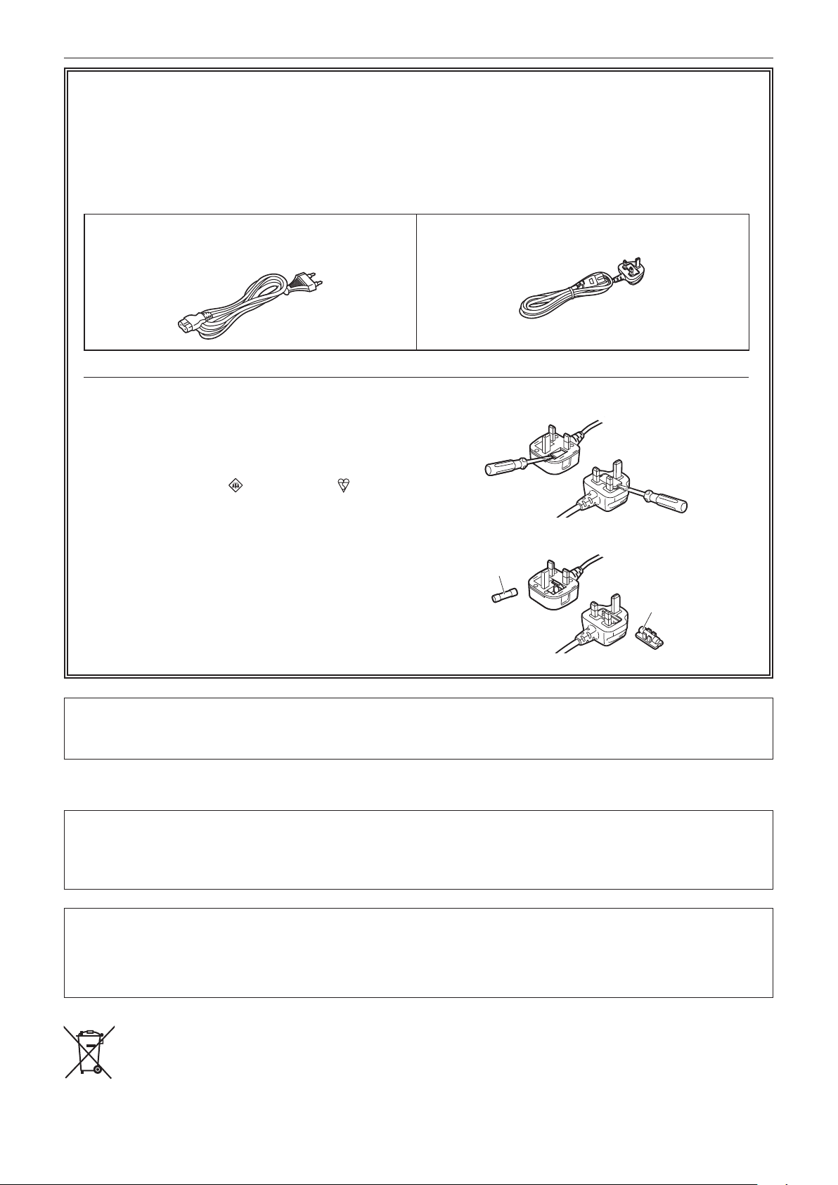
This product is equipped with 2 types of AC mains cable. One is for continental Europe, etc. and the other one
is only for U.K.
Appropriate mains cable must be used in each local area, since the other type of mains cable is not suitable.
TYPE C
(FOR CONTINENTAL EUROPE, ETC.
Not to be used in the U.K.)
FOR U.K. ONLY
This appliance is supplied with a moulded three pin mains
plug for your safety and convenience.
A 5 amp fuse is fitted in this plug.
Should the fuse need to be replaced please ensure that
the replacement fuse has a rating of 5 amps and that it is
approved by ASTA or BSI to BS1362.
Check for the ASTA mark
body of the fuse.
If the plug contains a removable fuse cover you must
ensure that it is refitted when the fuse is replaced.
If you lose the fuse cover the plug must not be used until
a replacement cover is obtained.
A replacement fuse cover can be purchased from your
local Panasonic Dealer.
or the BSI mark on the
TYPE BF
(FOR U.K. ONLY)
How to replace the fuse
1. Open the fuse compartment with a screwdriver.
Or
2. Replace the fuse.
Fuse
Or
Fuse
For Turkey
EEE Yönetmeliğine Uygundur.
EEE Complies with Directive of Turkey.
The rating plate is on the underside of the Camera Recorder, Battery Charger and AC Adaptor.
This equipment is in compliance with the essential requirements and other relevant provisions of
Directive 1999/5/EC.
Customers can download a copy of the original DoC for this product from our DoC server:
http://www.ptc.panasonic.de/
Manufactured by: Panasonic Corporation, Osaka, Japan
Importer’s name and address of pursuant to EU rules:
Panasonic Marketing Europe GmbH
Panasonic Testing Centre
Winsbergring 15, 22525 Hamburg, Germany
– 3 –
Read this rst!
rBatteries that may be used with this product (Correct as of March 2014)
Panasonic VW-VBD58 batteries may be used with this product.
Note regarding the Power Management function specified under COMMISSION REGULATION (EC) No
1275/2008 implementing Directive 2009/125/EC of the European Parliament and of the Council.
This device is designed and manufactured for use at a broadcasting station and/or in a similar environment.
This device is not equipped with a Power Management function or the Power Management function is set to OFF
as it will prevent the device from fulfilling its intended purpose for the reasons below.
1. If the device is a Studio Camera, a Weather Camera, a Mixer or other processor:
A Power Management function may cause the device to suddenly stop during recording or while On Air.
2. If the device is a Studio Monitor:
A Power Management function may cause video for the confirmation of whether a signal is normal, or whether
the signal has been lost, to be un-viewable.
3. If the device is a Camera Recorder:
A professional camera recorder must be able to start quickly at any time, but a Power Management function
will cause an increase in the time taken to resume from Stand-by mode.
It has been found that counterfeit battery packs which look very similar to the genuine product are made
available to purchase in some markets. Some of these battery packs are not adequately protected with internal
protection to meet the requirements of appropriate safety standards. There is a possibility that these battery
packs may lead to fire or explosion. Please be advised that we are not liable for any accident or failure occurring
as a result of use of a counterfeit battery pack. To ensure that safe products are used we would recommend that
a genuine Panasonic battery pack is used.
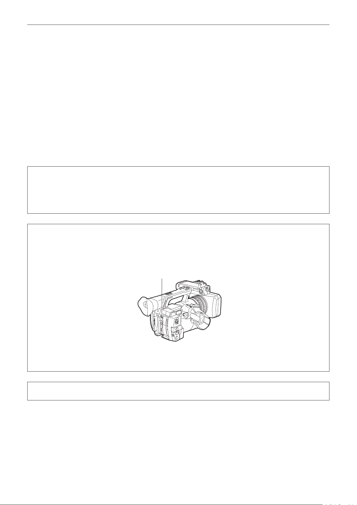
To remove the battery
Main Power Battery (Lithium ion Battery)
(Refer to page 26 for the detail.)
Press the battery release button.
Battery release button
Back-up Battery (Lithium Battery)
• For the removal of the battery for disposal at the end of its service life, please consult your dealer.
Battery Charger / AC Adaptor
Disconnect the AC mains plug from the AC mains socket when not in use.
– 4 –

Read this rst!
P2HD 5 Year Warranty Repair Program*
1
Thank you for purchasing this Panasonic P2HD device.
Register as a user for this device to receive a special service warranty up to five years of free warranty repairs.
Customers who register as users on the website will receive an extended warranty repair valid for up to
five years.
1st year 2nd year 3rd year 4th year 5th year
P2HD device
*1: Please note that this extended warranty is not available in some countries/regions. *2: Not all models eligible for extended
warranty coverage. *3: The basic warranty period may vary depending on the country/region. *4: Not all repair work is covered by
this extended warranty. *5: The maximum warranty period may be adjusted depending on the number of hours the device has been
used.
2
*
Basic warranty
3
*
Extended warranty repair
4
*
5
*
Free 5 years of Warranty Repairs
Make sure to save the “Registration Notice” e-mail
Purchase
P2 product
Register online
within 1 month
“Registration Notice”
e-mail sent
during the warranty period.
Details about user registration and the extended warranty: http://panasonic.biz/sav/pass_e
Please note, this is a site that is not maintained by Panasonic Canada Inc. The Panasonic Canada Inc. privacy policy does not apply and is not applicable in relation to any
information submitted. This link is provided to you for convenience.
– 5 –

f SDXC logo is a trademark of SD-3C, LLC.
f HDMI, HDMI logo, and High-Denition Multimedia Interface are trademarks or registered trademarks of HDMI Licensing LLC in the United States and/
or other countries.
f MMC (Multi Media Card) is a registered trademark of Inneon Technologies AG.
f Microsoft
f Screenshots are used according to Microsoft Corporation guidelines.
f Apple, Macintosh, Mac OS, QuickTime, iPad, and iPhone are trademarks or registered trademarks of Apple Inc. in the United States and/or other
countries.
f Java and all Java-based trademarks are trademarks or registered trademarks of Sun Microsystems, Inc. in the United States.
f All other names, company names, product names, etc., contained in this instruction manual are trademarks or registered trademarks of their
respective owners.
f This product is licensed under the AVC Patent Portfolio License. All other acts are not licensed except private use for personal and non-prot purposes
such as what are described below.
f Use of DCF Technologies under license from Multi-Format, Inc.
®
and Windows® are registered trademarks or trademarks of Microsoft Corporation in the United States and/or other countries.
- To record video in compliance with the AVC standard (AVC Video)
- To play back AVC Video that was recorded by a consumer engaged in a personal and non-commercial activity
- To play back AVC Video that was obtained from a video provider licensed to provide the video
Visit the MPEG LA, LLC website (http://www.mpegla.com/) for details.
How to read this document
r Illustrations
f Illustrations of the camera, menu screens, and other items, may vary from the actual items.
r Conventions used in this manual
f Words and phrases in [ ] brackets indicate details and content displayed in the viewnder or LCD monitor.
f Words and phrases in < > brackets indicate design text used on this camera, such as button names.
r Reference pages
f Reference pages in this document are indicated by (page 00).
r Terminology
f SD memory card, SDHC memory card, and SDXC memory card are referred to as “SD memory card”.
f A memory card with the “P2” logo such as AJ-P2E064AG memory card (optional) is referred to as a “P2 memory card”.
f A memory card with the “microP2” logo such as AJ-P2M032AG memory card (optional) is referred to as a “microP2 memory card”.
f P2 memory card and microP2 memory card are referred to only as “P2 card” unless distinguished otherwise.
f Media such as external hard disk drives (HDD) connected to USB are referred to as “storage devices”.
f Video that is created during a single recording operation is referred to as a “clip”.
– 6 –

Contents
Contents
Read this rst! 2
Chapter 1 Overview 9
Before using the camera 10
Use of the camera on a system 12
Basic conguration devices 12
Expanded conguration devices 12
What you can do with this camera 13
Recording to the memory card 13
Linking to external devices 13
Connecting to the network 14
Chapter 2 Description of Parts 15
Left side 16
Right side 18
Front side, rear side 20
Top side 2 2
Chapter 3 Preparation 24
Power supply 25
Charging the battery 25
Attaching and removing the battery 26
Using the AC adaptor 26
Attaching and adjusting accessories 28
Adjusting the grip strap 28
Attaching the shoulder strap 28
Attaching the lens hood 28
Attaching the eye cup 29
Attaching the front microphone 30
Attaching a tripod 30
Turning on/off the power 31
How to turn on the power 31
How to turn off the power 3 1
Setting the date/time of the internal clock 32
P2 card 33
Inserting a P2 card 33
Removing a P2 card 34
Preventing accidental erasure 34
P2 card access LEDs and status of P2 cards 34
P2 card recording time 35
CPS (Content Protection System) 36
How to handle data recorded on P2 cards 36
Assigning functions to the USER buttons 37
Adjusting and setting the LCD monitor 39
Using the LCD monitor 39
Adjusting the LCD monitor 39
Mirror shooting 39
Highlighting the outlines of images 39
Adjusting and setting the viewnder 40
Using the viewnder 4 0
Adjusting the viewnder 40
Highlighting the outlines of images 40
Tally lamp 4 1
Chapter 4 Shooting 42
Basic procedures 43
Preparation 43
Shooting 43
Selecting the resolution, codec, and video format for recording 44
Adjustable settings when shooting 46
Iris 46
Gain 4 6
Super gain 46
Brightness adjustment 46
Macro 46
Focusing (manual focus) 46
Focus assist function 47
Area mode function 48
Level gauge function 49
Adjusting the white and black balance 50
Adjusting the white balance 50
Adjusting the black balance 51
Using the zoom function 53
Setting the <ZOOM> switch 53
Adjusting the zoom position 53
Zoom ring 53
Adjusting image quality 54
Detail function 54
Skin tone function 54
RB gain control function 55
Chroma setting function 55
Matrix function 55
Color correction function 56
Black control function 5 6
Gamma function 56
Knee function 56
High color function 57
White clip function 57
Setting the electronic shutter 58
Shutter mode 58
Adjusting with the <SEL/PUSH SET> dial button and <MODE/
MENU CANCEL> button 5 8
Flash band compensation (FBC) function 59
Setting the ash band compensation function 59
Variable frame rate (VFR) recording function 60
Native variable frame rate recording 60
Standard variable frame rate recording (pull-down recording) 6 0
Selecting audio input and adjusting recording levels 62
Selecting audio input signals 62
Using the built-in microphone 62
Using the external microphone and audio device 62
Adjusting the recording level 63
Displaying the audio level detailed 63
Getting position information using the GPS 64
Special recording functions 6 5
Pre-recording 65
Interval recording 6 5
One-shot recording 66
Loop recording 66
One-clip recording 67
Simultaneous recording 68
Hot swap recording 68
Recording check function 69
Shot mark recording function 69
Text memo recording function 6 9
Convenient shooting functions 70
Low angle shooting 7 0
Scan reverse shooting 70
Zebra patterns display 70
Displaying the center marker 70
Displaying the safety zone marker 7 0
Displaying frame marker 71
Checking and displaying the shooting status 71
Changing image size 71
Image stabilization function 7 1
Dynamic range stretcher function 71
Backlight compensation 71
Color bars 71
Time stamp function 71
Deleting last clip function 72
Waveform monitor function 72
Direct menu operation 7 2
Multi formats 73
Selecting recording signals 7 3
System modes and recording functions 73
List of recording settings and recording functions 75
Selecting video output 7 6
Recording/playback and output format list 7 7
Dual codec recording 78
Dual codec recording setting 78
Recording the proxy data 78
Recording to the SD memory card 78
Checking the proxy data 79
Error displays about proxy data recordings 80
Handling setting data 8 2
Setting data le conguration 8 2
Handling SD memory cards 8 2
Performing operations on SD memory cards 83
How to use user data 84
How to use scene le data 8 4
How to restore the scene le or menu setting status to the
factory settings 86
Saving to an SD memory card and loading saved data 86
Selection of external reference signal and generator lock
setting 87
– 7 –

Contents
Locking the video signal to the external reference signal 87
Connecting to external devices in USB host mode 151
Setting the time data 88
Recording of time codes and user bits 88
User bits settings 91
How to input user bits 92
Setting the time code 92
Externally locking the time code 93
Supplying the time code externally 95
Connecting and setting the genlock and time code input/output 95
Setting and displaying the counter 9 6
Chapter 9 Network Connection 159
Network connection 160
Available functions 160
Operating environment 160
Preparing for connection 161
For wireless LAN 161
For wired LAN 162
Network settings 163
Chapter 5 Playback 97
Basic procedures 98
Preparation 98
Playback 98
Thumbnail operations 9 9
Thumbnail operation overview 99
Thumbnail screen 99
Selecting thumbnails 101
Setting thumbnail screen display 101
Changing thumbnails 102
Shot mark 103
Text memo 103
Deleting clips 104
Restoring clips 104
Reconnecting incomplete clips 105
Copying clips 105
Setting clip metadata
Formatting a P2 card 107
Formatting SD memory cards 108
Properties
105
108
Chapter 6 Menu Operations 113
Setting menu structure 1 1 4
Menu types and how to open them 11 4
Main menu structure 114
Setting menu display 11 5
Setting menu basic operations 11 5
Setting [USER MENU] 116
Setting menu initialization 116
Menu list 11 8
[SCENE FILE] 11 8
[SYSTEM MODE] 123
[USER SW] 124
[SW MODE] 125
[AUTO SW] 126
[RECORDING SETUP] 127
[CLIP] 128
[AUDIO SETUP] 130
[OUTPUT SEL] 131
[NETWORK SETUP] 133
[DISPLAY SETUP] 134
[CARD FUNCTIONS] 137
[OTHER FUNCTIONS] 137
[MAINTENANCE] 137
[DIAGNOSTIC] 138
[USER MENU SEL] 138
Wireless LAN settings 163
Wired LAN settings 164
P2 browser function settings and connection status check 166
FTP client function setting 166
Using FTP client function 168
FTP server folder list (FTP explorer screen) 168
Deleting clips on the FTP server 169
Viewing information of clips on FTP server 169
Transferring from a P2 card to an FTP server (copy) 170
Transferring from an SD card to an FTP server (export) 170
Chapter 10 Maintenance and Inspection 172
Maintenance 173
Charging the built-in battery 173
Frequently asked questions 174
Power supply 174
Battery 174
Shooting 174
Editing 174
Playback 174
Others 175
Warning system 176
Cases indicated by error codes 176
Cases indicated by error messages 176
Updating the camera rmware 180
Cleaning and storing 181
Cleaning the camera recorder 181
Cautions when storing the camera recorder 181
Chapter 11 Specication 182
Specications 183
Dimensions 183
Specications 183
Index 188
[OPTION MENU] list 139
[AWB PRE CONTROL] 139
[CAM REMOTE ADJ.] 139
[ENG SECURITY] 139
Chapter 7 Display 140
Screen status display 141
Conguration of status display on screen 141
Selecting display items on screen 141
Displaying screen 141
Checking and displaying shooting status 145
Mode check display 146
Chapter 8 Connecting to External Devices 148
Connecting with headphones, remote control, or TV/
monitor 149
Headphones 149
Remote control 149
TV/monitor 149
Connection function via <USB2.0 DEVICE> or <USB3.0
HOST> terminal 151
Connecting to a computer in the USB device mode 151
– 8 –

Chapter 1 Overview
Before using the camera, read this chapter.
For accessories, refer to the leaet supplied with the product.

Chapter 1 Overview — Before using the camera
Before using the camera
r When using this product during rain or snow or when at the beach, be careful that water does not get inside the camera recorder.
Water causes damage to the camera recorder and memory card. (Repair may be impossible)
r Keep the camera recorder away from devices (TVs, TV games, etc.) that produce magnetism.
f If you use the camera recorder on or near TVs, video and sound data may be distorted by electromagnetic waves.
f Strong magnetic elds produced by speakers and large motors may cause damage to recorded contents and may distort images.
f Electromagnetic waves emitted by microcomputers may have a harmful effect on the camera recorder and may corrupt video and sound data.
f The camera recorder may not operate properly if it receives harmful effects from devices that produce magnetism. If this happens, turn off the camera
recorder and either remove the battery or unplug the AC adaptor from the power outlet. Then, replace the battery or reconnect the AC adaptor. After
that, turn on the camera recorder.
r Do not use the camera recorder near radio transmitters or high-voltage devices.
If you use the camera recorder near radio transmitters or high-voltage devices, the recorded video and sound data may suffer harmful effects.
r When using the camera recorder at the beach, etc., be careful that sand and dust do not get inside the camera recorder.
Sand and dust may damage the camera recorder and memory card. (Be careful when inserting and removing the memory card)
r Battery charger and battery
f If the <CHARGE> lamp continues blinking even when the battery is at its optimal temperature, the battery or battery charger may be damaged.
Contact a dealer.
f If the battery is warm, it will take longer than usual to charge.
f If you use the battery charger near a radio, the radio sound may be distorted. Keep the battery and battery charger at least 1 m away from radios
when in use.
f Noise may be emitted when using the battery charger, but this is not a malfunction.
r When carrying the camera recorder, be careful not to drop it.
f Strong shocks will damage the camera recorder body and it may not operate properly.
f If you carry the camera recorder, use a grip strap or shoulder strap and handle it carefully.
r Do not apply insecticide or volatile materials to the camera recorder.
f If insecticide or volatile materials come into contact with the camera recorder, the camera recorder body may warp and the paint may come off.
f Do not allow the camera recorder to remain in contact with rubber or vinyl objects for a long period of time.
r After using the camera recorder, either remove the battery or disconnect the AC cable from the power outlet.
r Battery characteristics
The battery is a rechargeable lithium-ion battery. It produces electrical energy via an internal chemical reaction. This chemical reaction is easily
inuenced by the surrounding temperature and humidity, so the effective usage time of the battery is reduced when the surrounding temperature is hot
or cold. When used in extremely low temperature environments, the effective usage time is approximately ve minutes.
When the battery is in an extremely hot environment, its protective function will operate and the camera recorder cannot be used temporarily.
r After using the camera recorder, be sure to remove the battery.
Be sure to remove the battery from the camera recorder. (If the battery is left in the camera recorder, it will continue to consume a small amount of
electric current even when the power is turned off)
If the battery is left inside the camera recorder for a long time, it will over discharge and may become unusable even if it is recharged.
Do not remove the battery when the power is turned on.
Turn off the power and remove the battery after the operation lamp goes completely out.
r Take proper care of the battery terminal.
Do not allow dust or foreign objects on the battery terminal.
Also, if you drop the battery by mistake, make sure that the battery body and the terminal are not warped.
Inserting a deformed battery into the camera recorder or attaching it to the battery charger may cause damages on the camera recorder or battery
charger.
r Cautions when throwing memory cards away or transferring them to others
Formatting memory cards or deleting data using the functions of the camera or a computer will merely change the le management information: it will
not completely erase the data on the cards. When throwing these cards away or transferring them to others, either physically destroy them or use a
data deletion program for computers (commercially available) to completely erase the data. Users are responsible for managing the data stored in their
memory cards.
r LCD monitor and viewnder
f If the same image or letters are allowed to be displayed on the LCD monitor for a long time, the image may be burned into the screen. It will return to
normal after leaving the camera recorder turned off for several hours.
f Condensation sometimes forms on the LCD panel of the LCD monitor in locations subject to extreme temperature differences. If this happens, wipe
with a soft, dry cloth.
f If the camera recorder is very cold, the LCD monitor will be slightly darker than normal immediately after the power is turned on. The screen will return
to its regular brightness when the temperature inside increases.
– 10 –

Chapter 1 Overview — Before using the camera
f Since the viewnder of the camera uses organic EL, if the same image or letters are allowed to be displayed for a long time, the image may be burned
into the screen. There is no problem with the recorded images.
Switch the screen by turning off the screen or by using the eye sensor, etc.
f The LCD monitor and viewnder (organic EL) are highly-precisely managed so that at least 99.99% of the dots are effective pixels and 0.01% or less
are invalid pixels and always lit. This is not a malfunction and it has no effect whatsoever on the recorded images.
r Do not point the eye piece of the lens and viewnder at the sun.
Doing so might damage the components inside.
r Protective cap for the terminal
Place a protective cap on connection terminals not being used.
r GPS
GPS (Global Position System) satellite is managed by the United States Department of State and its precision is sometimes intentionally changed.
Position it in a location where there is a good view of the sky and there is no inuence of obstacles such as roofs and trees, etc.
Depending upon the surrounding environment and the time, it may take a long time to position and errors may be larger.
r Caution regarding laser beams
The MOS sensor may be damaged if the MOS sensor is subjected to light from a laser beam.
Take sufcient care to prevent laser beams from striking the lens when shooting in an environment where laser devices are used.
r Note the following points.
f If you prepare to record important images, always shoot some advance test footage to verify that both pictures and sound are being recorded
normally.
f Should video or audio recording fail due to a malfunction of the camera or the P2 cards used, we will not assume liability for such failure.
f Set up or check the calendar and time zone before recording (Setting the date/time of the internal clock). These settings have an effect on the
management and playback order for recorded contents.
r Software information about this product
1 This product includes software licensed under GNU General Public License (GPL) and GNU Lesser General Public License (LGPL), and
customers are hereby notied that they have rights to obtain, re-engineer, and redistribute the source code of these software.
2 This product includes software licensed under MIT-License.
3 This product includes software developed by the OpenSSL Project for use in the OpenSSL Toolkit (http://www.openssl.org/).
4 This product includes software licensed under OpenBSD License.
5 This product includes PHP, freely available from <http://www.php.net/>.
6 This software is based in part on the work of the Independent JPEG Group.
For details on these descriptions (originally provided in English) and how to obtain the source code, visit the following website.
http://pro-av.panasonic.net/
We do not accept inquiries about the details of the source code obtained by the customer.
r Precautions when installing USB drivers
For the latest information on the driver, visit the following website.
http://pro-av.panasonic.net/
f Install the required driver into your computer from the website.
f For installation procedure of the driver, refer to the installation manual on the website.
– 11 –

Chapter 1 Overview — Use of the camera on a system
Use of the camera on a system
Parts other than the camera are optionally available. Use the following recommended parts.
Basic conguration devices
Equipment necessary for shooting with the camera, such as batteries, etc.
Part name Part No. Remark
Super-directional electret stereo microphone
(phantom +48V)
Battery
SD memory card*
P2 memory card*
microP2 memory card*
* For the latest information on P2 cards and SD memory cards that are not described in the Operating Instructions, visit the support desk at the following website:
http://pro-av.panasonic.net/
Expanded conguration devices
You can also use the following devices in addition to the basic conguration devices.
Part name Part No. Remark
Wireless module AJ-WM30 “For wireless LAN” (page 161)
AG-MC200G “Attaching the front microphone” (page 30)
VW-VBD58 (7.2 V, 5800 mAh: Product comparable
to the included battery)
CGA-D54/CGA-D54s (7.2 V, 5400 mAh)
Visit the support desk at the website* “P2 card” (page 33)
“Attaching and removing the battery” (page 26)
– 12 –
Chapter 1 Overview — What you can do with this camera
What you can do with this camera
This camera is a P2 hand-held camera recorder with the following features.
f The camera has an optical 22x cam-type zoom and a newly-developed 1/3-type 2.2 million pixel 3MOS sensor with high sensitivity F11 (59.94 Hz)/F12
(50 Hz) and low noise.
f In addition to AVC-Intra, as a recording codec, the camera also has a low-rate and full HD (1920×1080, 4:2:2, 10-bit) image quality AVC-LongG 50/
AVC-LongG 25, and AVC-LongG 12 (4:2:0, 8-bit), which allow long-term recording.
f It is compatible with both microP2 memory cards and P2 memory cards.
f It supports progressive full frame rate shooting in 1080/60P and 1080/50P, output of 3G SDI/HDMI, and operations using AVC proxy video.
f In addition to metadata input and playlist editing* by using both wired and wireless LAN connections, you can send proxy les to the network server by
connecting 4G adaptor*.
* Schedule to support when future versions are upgraded
Recording to the memory card
P2 card
The following can be recorded on the P2 card:
f HD/SD recording
f AVC Ultra system codec support
f Simultaneous recording (microP2 memory card only)
f Dual codec recording
f Variable frame rate
Slow & quick motion recording
SD memory card
Settings for user les and scene les, etc. can be stored in and loaded from the SD memory card.
Linking to external devices
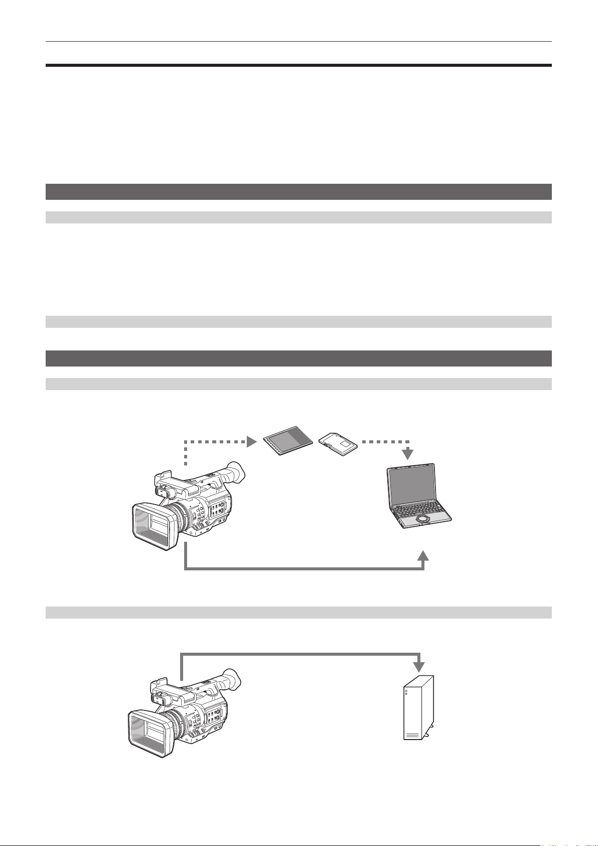
USB device mode
Data (les) for performing nonlinear editing on a computer are transferred.
P2 memory card, microP2 memory card*
USB 2.0 (device mode)*
*1 P2 memory cards and microP2 memory cards are optionally available. They are not supplied with the camera.
*2 The USB 2.0 cable is not supplied with the camera. Prepare a commercial USB 2.0 cable (double-shielded for noise suppression).
2
USB host mode (<USB3.0 HOST> terminal connection)
The camera directly controls the hard disk drive to transfer data.
USB 3.0*
1
Personal computer
External storage device
* A USB 3.0 cable is not supplied with this product. Use a commercially sold USB 3.0 cable (with double shielding for noise reduction).
– 13 –
Chapter 1 Overview — What you can do with this camera
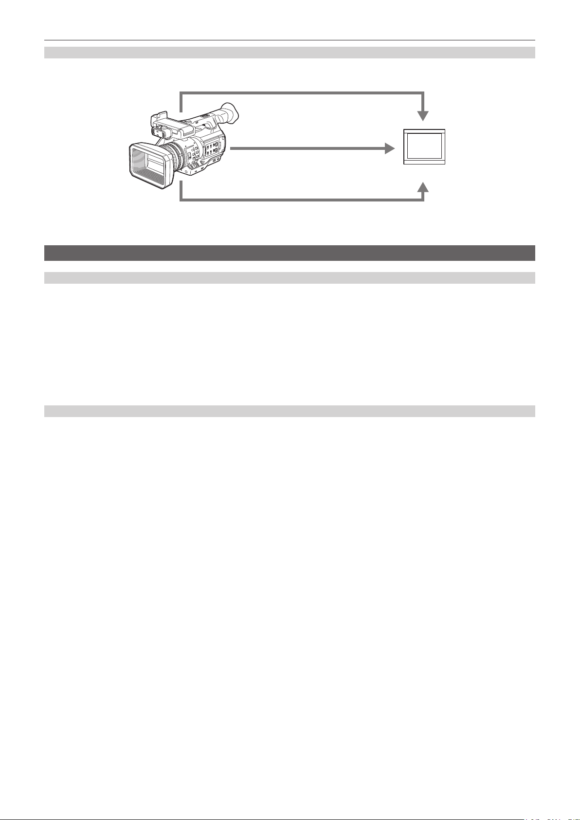
Connecting to monitor
A monitor can be connected to output images.
Audio pin cable*
1
HDMI cable*
2
Monitor
BNC cable (composite/HD SDI/SD SDI)*
*1 Cables are optionally available. They are not supplied with the camera.
*2 Use an HDMI cable (optional) with double shielding. For the HDMI cable, using Panasonic HDMI cable is recommended.
*3 For the BNC cable (optional) connected to the <SDI OUT> terminal, prepare a double-shielded cable equivalent to 5C-FB.
3
Connecting to the network
Wired LAN connection
The following operations are available on your computer via LAN terminal:
f Camera status check
f Thumbnail image check
f Proxy playback*
f Download of proxy le/clip management information
f Displaying/editing of metadata
f Adding/deleting of metadata (shot mark or text memo)
f Camera remote control (collective operations of recording control and time code/user bits)
In addition, clip transferring can be performed by the FTP client function via the LAN terminal.
* Contents which were recorded with AVC-LongG 6 cannot be played back.
Connecting using wireless LAN connection and 4G adaptor*
Attaching the wireless module AJ-WM30 (optional) to the <USB2.0 HOST> terminal (sub-host) of the camera allows you to connect the camera via
wireless LAN (IEEE 802.11).
The following operations are available using your tablet, smartphone, and computer.
f Camera status check
f Thumbnail image check
f Proxy playback
f Displaying/editing of metadata
f Adding/deleting of metadata (shot mark or text memo)
f Camera remote control (collective operations of recording control and time code/user bits)
In addition, clip transferring can be performed by the FTP client function via wireless LAN (access point connection) or 4G adaptor*.
* Schedule to support when future versions are upgraded
– 14 –

Chapter 2 Description of Parts
This chapter describes the names, functions, and operations of parts on the camera.
Left side
Chapter 2 Description of Parts — Left side
20 21
22
23
26 27
2524
28
29
30
31
1
2
3
4
5
7 9 11 13 14
6 8
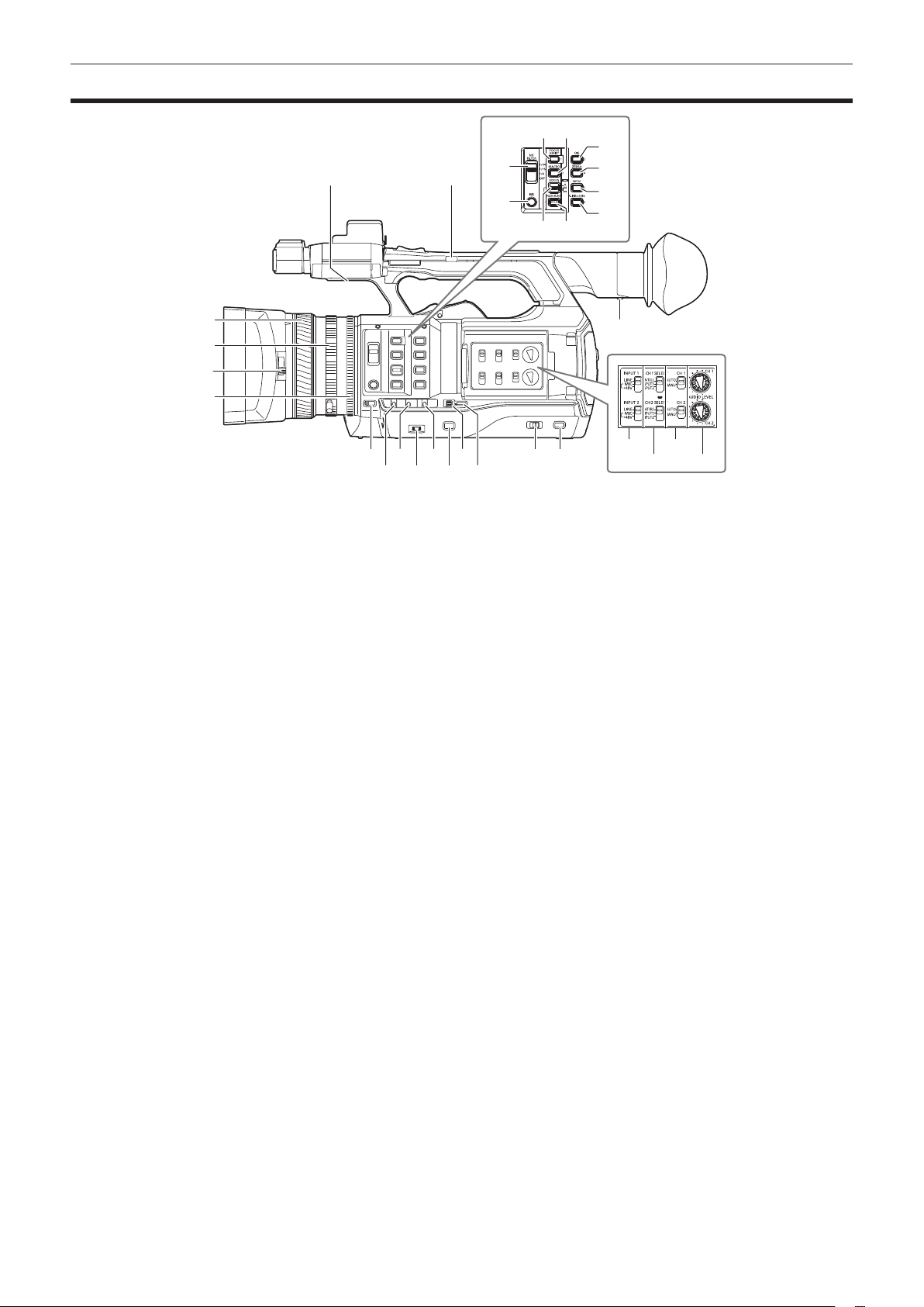
1 Focus ring (page 46)
Focus manually when the <FOCUS> switch is set to <M>.
2 Zoom ring (page 53)
Adjust the zoom manually when the <ZOOM> switch is set to <MANUAL>.
3 Lens cover switching lever (page 29)
Open/close the lens cover.
4 Iris ring (page 46)
Adjust the lens iris manually when the manual iris is set with the <IRIS> button.
5 <ZOOM> switch (page 53)
Select the operation of the zoom.
<SERVO>: You can use the motor-driven zoom using the zoom lever.
<MANUAL>: You can operate the zoom ring manually to adjust the angle of view.
6 <DISP/MODE CHK> switch (page 71)
This is the spring switch to check the status of the shooting, etc.
f Push this switch towards the <OFF> side to clear all displays except the display of the operation status, frame display such as an area, counter,
marker, and safety zone.
f Push this switch towards the <CHK> side to display all information such as setting status of the functions for the shooting, the list of functions
assigned to the USER buttons on the LCD monitor during shooting stand-by or shooting. Each time the switch is pushed towards the <CHK> side,
the display of the status switches in turn.
7 <GAIN> switch (page 46)
Switch the brightness of the screen according to the lighting conditions under which you are shooting.
8 <F.AUDIO LEVEL> dial (page 63)
In the following conditions, the recording levels for the audio channels 1 to 4 can be adjusted.
f When the <CH1>/<CH2> switch is set to <MANU>
f When [AUTO LEVEL CH3]/[AUTO LEVEL CH4] is set to [OFF] in the main menu → [AUDIO SETUP] → [RECORDING CH SETTING]
Assignment of audio channels 1 to 4 can be performed in the main menu → [AUDIO SETUP] → [RECORDING CH SETTING] → [FRONT VR
SELECT].
9 <WHITE BAL> switch (page 50)
Select the method for adjustment of the white balance.
<PRST>: Set the white balance to the preset value. Each time the <AWB> button is pressed, [3200K], [5600K], and [VAR] are toggled.
<A>/<B>: Select when using the stored value of the adjustment of the white balance.
10 <MENU> button (page 115)
Press this button to display [USER MENU]. Press this button for 3 seconds or more to display the main menu. Press it again to return to the original
image.
11 <SEL/PUSH SET> dial button (page 115)
Move, select, and set the items in the setting menu while the setting menu is displayed.
Set the preset values of the shutter, synchro scan, variable frame rate value, and white balance.
12 <MODE/MENU CANCEL> button (page 58)
f When the setting menu is not displayed, each press of the button switches modes to change the variable value of shutter speed, variable frame
rate, and white balance.
f When the setting menu is displayed, setting of the menu items is canceled and the previous screen is displayed.
10 12
15
16 18
17 19
– 16 –

Chapter 2 Description of Parts — Left side
13 <AUTO/MANUAL> switch
Select the method to adjust the focus, gain, iris, white balance, and shutter speed at shooting. You can set the function to assign to <AUTO> in the
main menu → [AUTO SW].
<AUTO>: Adjust automatically. (Auto mode)
<MANUAL>: Adjust manually. (Manual mode)
14 <SLOT SEL> button
Select the microP2 memory card slot for the target of recording.
This button can be used as the USER button (USER7). (page 37)
15 Diopter adjustment lever (page 40)
Adjust the diopter scale so that the viewnder screen can be viewed clearly.
16 <INPUT 1>/<INPUT 2> switch (page 62)
Switch audio input signals connected to the <AUDIO INPUT 1>/<AUDIO INPUT 2> terminal.
<LINE>: Select when audio equipment is connected by the line input.
<MIC>: Select when the external microphone is connected.
<+48V>: Select when the external microphone is connected and the microphone needs power supply.
17 <CH1 SELECT>/<CH2 SELECT> switch (page 62)
Select the audio to be recorded to audio channel 1/2.
<INT(L)>/<INT(R)>: Record left audio (right audio) of the built-in microphone.
<INPUT1>: Record input signals from the <AUDIO INPUT 1> terminal.
<INPUT2>: Record input signals from the <AUDIO INPUT 2> terminal.
18 <CH1>/<CH2> switch (page 63)
Select the method to adjust the input level of audio channel 1/2.
<AUTO>: Adjust automatically.
<MANU>: Adjust using the <AUDIO LEVEL CH1>/<AUDIO LEVEL CH2> dial.
19 <AUDIO LEVEL CH1>/<AUDIO LEVEL CH2> dial (page 63)
Adjust the recording level of audio channel 1/2.
20 Internal speaker
Output audio during playback.
When connecting the headphones to the headphones terminal, audio from the speaker turns off automatically.
21 HANDLE ZOOM switch (page 53)
Select the operation of the zoom lever (handle side).
<FIX>: Zoom in/out with the speed set in the main menu → [SW MODE] → [H.ZOOM SPEED].
<VAR>: Zoom speed changes depending on how strong the lever is pushed. (When pushed gently, the speed becomes slower, and when pushed
strongly, it becomes faster.)
<OFF>: The zoom lever does not work.
22 <ND FILTER> switch (page 46)
Select the lter to suit the illumination of the subject.
<1/64>: Reduce the amount of light entering the MOS sensor to 1/64.
<1/16>: Reduce the amount of light entering the MOS sensor to 1/16.
<1/4>: Reduce the amount of light entering the MOS sensor to 1/4.
<OFF>: Does not use the ND lter.
23 <IRIS> button (page 46)
Select the method for adjustment of the lens iris.
24 <FOCUS ASSIST> button (page 47)
Switch on/off the focus assist function.
This button can be used as the USER button (USER1). (page 37)
25 <MACRO> button (page 46)
Switch on/off the macro function of the focus.
This button can be used as the USER button (USER2). (page 37)
26 <FOCUS> switch (page 46)
Select the focus function.
<A>: Changes to the auto focus mode. Adjust the focus automatically.
<M>: Changes to the manual focus mode. Control the focus ring manually to adjust the focus.
<c>: Changes to the manual focus mode after the focus distance is set to innity.
This is the spring switch. Even when the <FOCUS> switch is pushed towards the <c> side, the switch returns to the <M> position.
27 <PUSH AUTO> button (page 47)
When the button is pressed in manual focus mode, focus is adjusted automatically while it is pressed.
28 <OIS> button (page 71)
Switch on/off the image stabilization function.
This button can be used as the USER button (USER3). (page 37)
29 <ZEBRA> button (page 70)
Select the display of either zebra of marker.
This button can be used as the USER button (USER4). (page 37)
30 <WFM> button (page 72)
Select whether to display the waveform monitor on the LCD monitor.
This button can be used as the USER button (USER5). (page 37)
31 <A.IRIS.LEVEL> button
Switch on/off the auto iris function.
Set the target value of the auto iris level in the main menu → [SCENE FILE] → [A.IRIS LEVEL EFFECT].
This button can be used as the USER button (USER6). (page 37)
– 17 –
Right side
Chapter 2 Description of Parts — Right side
1
9
10
11
12
13
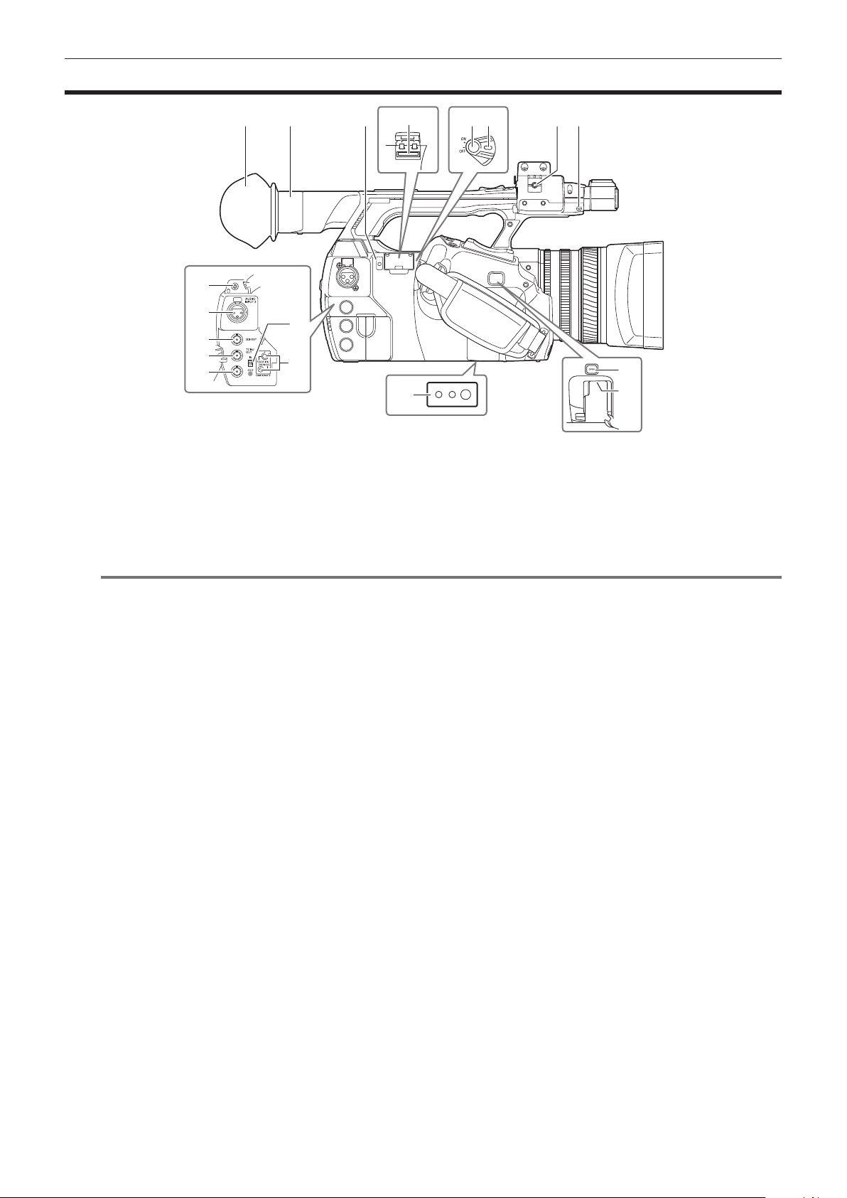
1 Eye cup (page 29)
2 Eye piece
3 Busy (active status indication) lamp (page 83)
Indicate the active status of the SD memory card, and is illuminated when the card is active.
4 SD memory card slot (page 83)
This is the insertion slot for the SD memory card (optional). Use the SD memory card for recording/opening the setting menu of the camera, or
uploading metadata or proxy recording, etc.
NOTE
@@
t Cautions when using SD memory cards
- On the camera, use SD memory cards that conform to the SD standard, SDHC standard, or the SDXC standard. When performing proxy
recording, use SDHC memory cards, SDXC memory cards, or SD memory cards with the class description of class2 or higher.
- MMC (Multi Media Card) cannot be used. (Bear in mind that taking pictures may no longer be possible if you use them.)
- When using miniSD/microSD cards with the camera, always install the adaptor specially designed for miniSD/microSD cards. (The camera will
not work properly if only the miniSD/microSD adaptor is installed. Make sure that the card has been inserted into the adaptor before use.)
- Use of Panasonic SD memory cards and miniSD/microSD cards is recommended. Be sure to format cards on the camera before use.
- Refer to our support desk at the following website for the latest information not included in these operating instructions.
http://pro-av.panasonic.net/
- SDHC memory cards are a standard that was established in 2006 by the SD Association for large-capacity memory cards that exceed 2 GB.
- SDXC memory cards are a standard that was established in 2009 by the SD Association for large-capacity memory cards that exceed 32 GB.
5 Recording button (grip side) (page 43)
Press this button to start recording. Press it again to stop recording.
Used for direct shooting in thumbnail mode.
6 Power switch (page 43)
Switch on/off the power.
7 Microphone cable clamp (page 30)
Used for securing the microphone cable.
8 Pin holder
Attach the zoom ring pin which is removed from the camera.
9 Headphones terminal (page 149)
This is the connecting terminal of headphones for audio monitor.
10 <AUDIO INPUT 2> terminal (XLR, 3-pin) (page 62)
Connect the audio equipment or the microphone.
11 <SDI OUT> terminal (page 95)
This is the output terminal for HD/SD SDI signals.
12 <TC IN/OUT> terminal (page 88)
This is the input/output terminal for time code.
Use the <IN/OUT> switch to select the input or output.
13 <GENLOCK IN/VIDEO OUT> terminal (page 93)
This is the input terminal for reference signals when setting the genlock to the camera section. This is the output terminal of the video for monitor.
Use the <IN/OUT> switch to switch the input or output.
14 <IN/OUT> switch (page 91)
Switch the input and output of the <TC IN/OUT> terminal and <GENLOCK IN/VIDEO OUT> terminal.
2 3
14
15
16
54 6
87
17
18
– 18 –

Chapter 2 Description of Parts — Right side
15 <CAM REMOTE> terminal (page 149)
Connect the remote control (optional) to control some functions remotely.
<FOCUS IRIS>: (3.5 mm mini jack) Control the focus operation and iris operation remotely.
<ZOOM S/S>: (2.5 mm mini jack) Control the zoom operation and start/stop operation of recording remotely.
16 Tripod holes
Attach the tripod. (bottom)
f Mounting hole size
- 1/4-20 UNC (screw length 5.5 mm or shorter)
- 3/8-16 UNC (screw length 5.5 mm or shorter)
17 <OPEN> button (page 161)
Use this button when opening the cover of the <USB2.0 HOST> terminal at the bottom of the button.
18 <USB2.0 HOST> terminal (sub-host) (page 161)
This is the terminal for the wireless LAN. Mount the wireless module AJ-WM30 (optional).
– 19 –
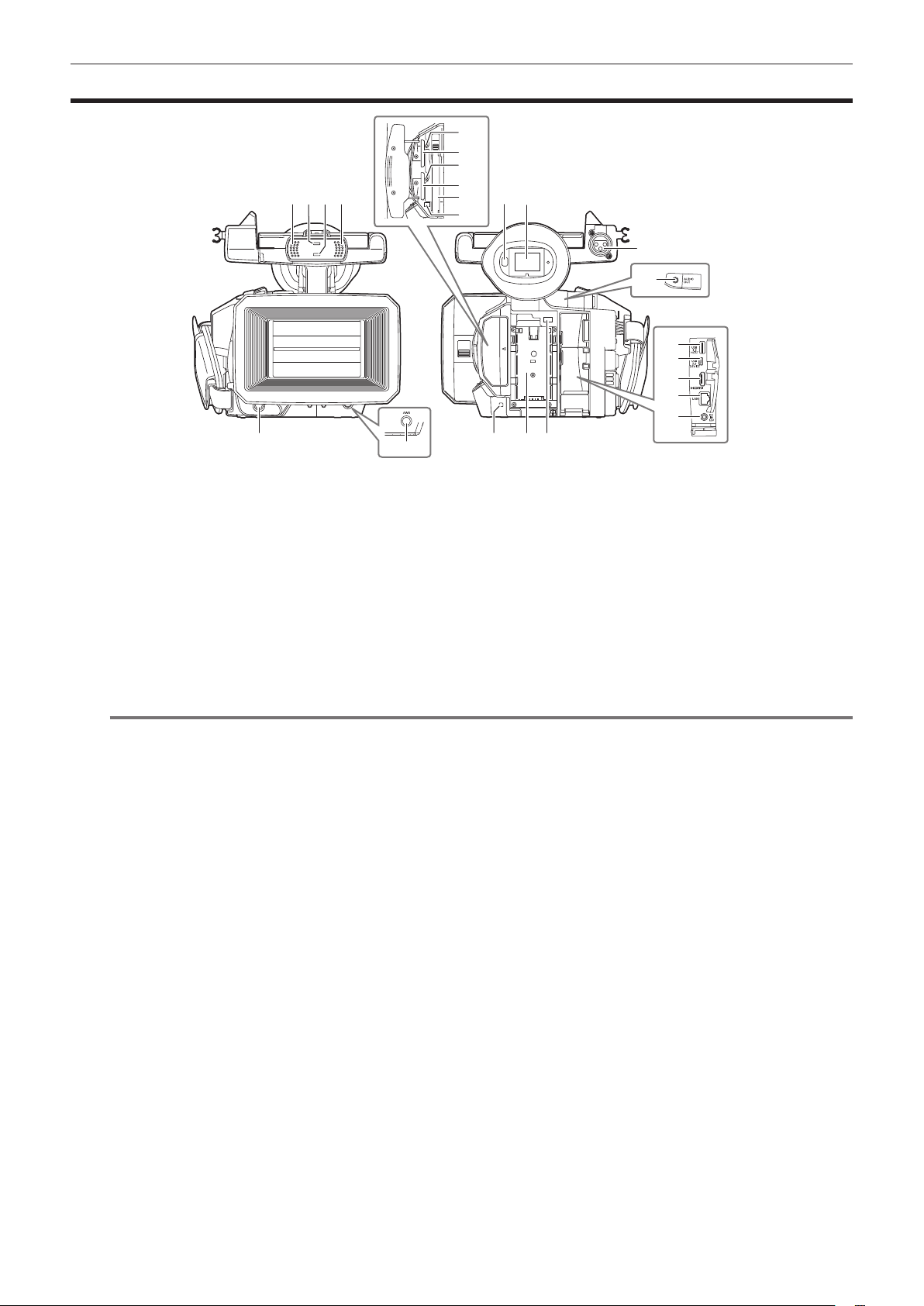
Chapter 2 Description of Parts — Front side, rear side
Front side, rear side
12
13
14
1 1
2 3
4
1 Built-in microphone (page 62)
This is the built-in stereo microphone.
2 Light sensor
Detects indoor and outdoor light.
3 Front tally lamp (page 41)
Lights during shooting. This lamp will blink when the battery level becomes low.
4 Recording button (front side) (page 43)
Press this button to start recording. Press it again to stop recording.
The operation of this button can be forbidden by the main menu → [SW MODE] → [FRONT REC].
5 <AWB> button (page 50)
Press this button to adjust the white balance. Press it for two seconds or more to adjust the white balance and then black balance.
6 Eye sensor (page 40)
Bring your eyes closer to display the screen on the viewnder.
NOTE
@@
t The eye sensor may not work properly depending on the shape of glasses in use, how you hold the camera, or by hitting the strong light around
the eye piece.
t The eye sensor does not work during video playback.
7 Viewnder (page 40)
8 <AUDIO INPUT 1> terminal (XLR, 3-pin) (page 30)
Connect the audio equipment or the microphone.
9 Rear tally lamp (page 41)
Light during shooting. This lamp will blink when the battery level becomes low.
10 Battery attachment (page 26)
11 Battery release button (page 26)
Remove the battery.
12 microP2 memory card 1 access LED (page 34)
Indicate the access status of recording and playback of the card inserted in the microP2 memory card slot 1.
13 microP2 memory card slot 1 (page 33)
14 microP2 memory card 2 access LED (page 34)
Indicate the access status of recording and playback of the card inserted in the microP2 memory card slot 2.
15 microP2 memory card slot 2 (page 33)
16 P2 memory card slot (page 33)
17 P2 memory card access LED (page 34)
Indicate the access status of recording and playback of the card inserted in the P2 memory card slot.
18 <AUDIO OUT> terminal (page 149)
Output audio signals recorded to audio channel 1/2.
19 <USB3.0 HOST> terminal (host) (page 151)
Connect external hard disk drive, etc.
20 <USB2.0 DEVICE> terminal (device) (page 151)
Connect to a computer with the USB 2.0 cable to transfer data.
21 <HDMI OUT> (monitor output) terminal (page 149)
This is the output terminal of the video for monitor.
5
15
16
17
76
8
18
19
20
21
22
23
11109
– 20 –

Chapter 2 Description of Parts — Front side, rear side
22 <LAN> terminal (page 162)
Connect the LAN cable.
23 <DC IN 12V> terminal (page 26)
This is the input terminal for the external power supply. Connect the supplied AC adaptor.
– 21 –
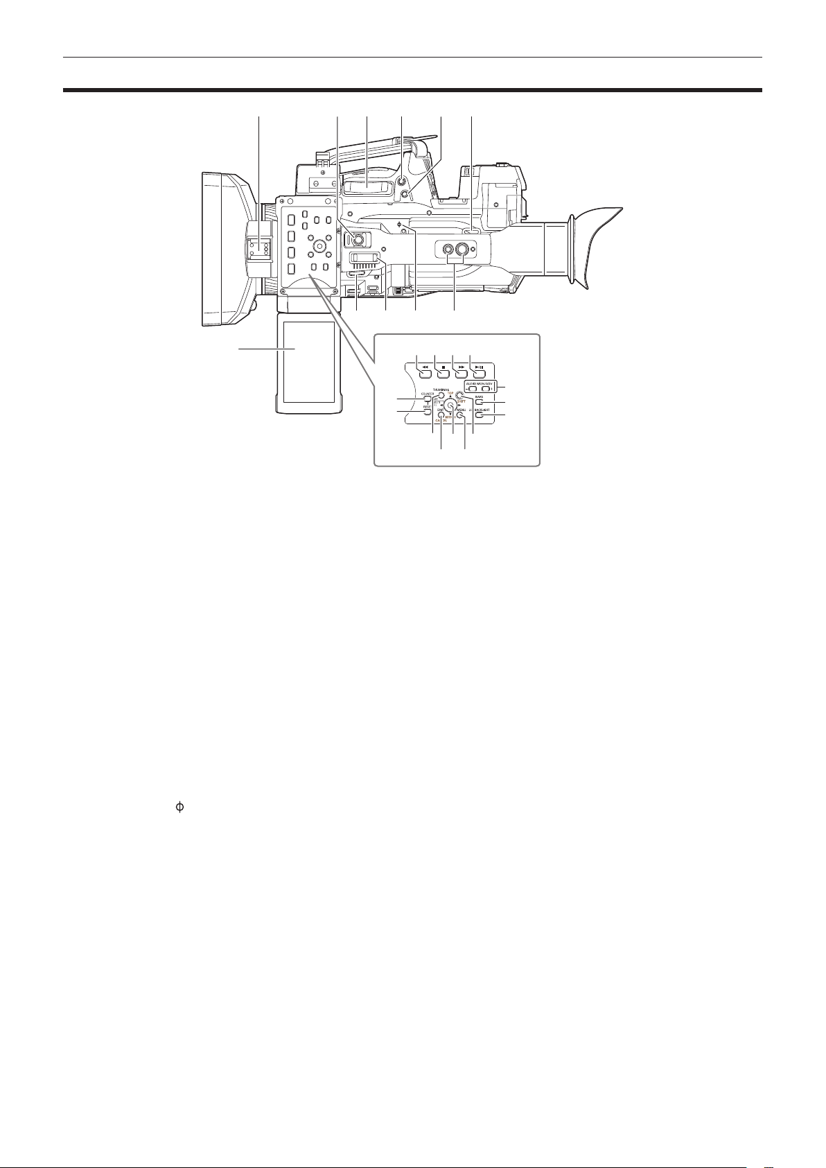
Top side
Chapter 2 Description of Parts — Top side
14 15 16
19
20
18
6
22
23
24
21
1
7
1 Light shoe
Attach the video light.
2 Recording button (handle side) (page 43)
Press this button to start recording. Press it again to stop recording.
This includes hold mechanism.
3 Zoom lever (grip side) (page 53)
Adjust the zoom of an image.
<T>: Zoom in the image.
<W>: Zoom out the image.
4 <IRIS> button (page 46)
Select the method for adjustment of the lens iris.
This button can be used as the USER button (USER8). (page 37)
5 <REC CHECK> button (page 43)
Press this button while recording is suspended, to play back the video and audio of the most recent clip for approximately three seconds.
6 Shoulder strap attachment (page 28)
Attach the shoulder strap.
7 LCD monitor (page 39)
8 Zoom lever (handle side) (page 53)
Adjust the zoom of an image.
<T>: Zoom in the image.
<W>: Zoom out the image.
9 Focal plane index <
Indicate the focal plane of the MOS sensor.
It provides a reference for measuring the accurate focal distance from the subject.
10 Handle mounting holes
Mount the handle.
f Mounting hole size
- 1/4-20 UNC (screw length 5.5 mm or shorter)
- 3/8-16 UNC (screw length 5.5 mm or shorter)
11 <COUNTER> button (page 92)
Switch the display item of the counter.
12 <RESET> button
Reset the display of the time counter.
13 <%> button
This works when the thumbnail screen is displayed.
Press this button during a pause to perform fast-reverse playback.
Press this button during playback to perform 4x speed reverse playback.
If it is pressed with playback paused, the clip being played back is paused at its start point (cued state).
>
2 53
6 109
4
8
13
11
12
17
– 22 –

Chapter 2 Description of Parts — Top side
14 <(> button
This works when the thumbnail screen is displayed.
Press this button to stop playback.
Press this button when you stop interval recording or one-shot recording, or when you end combining to the clip of one-clip recording.
15 <)> button
This works when the thumbnail screen is displayed.
Press this button during a pause to perform fast playback.
Press this button during playback to perform 4x speed playback.
If it is pressed with playback paused, the clip being played back is paused at the start point of the next clip (cued state).
16 <=/&> button
This works when the thumbnail screen is displayed.
Press this button to view playback image.
Press it during playback to pause playback.
17 <THUMBNAIL> button (page 99)
Press the button to display the thumbnail screen on the LCD monitor and viewnder. Press it again to return to the regular display.
18 <EXIT>/<CANCEL> buttons (page 101)
Restore the display to the previous state while the setting menu or property screen is displayed.
Press this button while holding down the <SHIFT> button to act as the cancel button. This is convenient, for example, for batch-canceling clip
selections.
19 Control stick (page 101)
Use this button to select a thumbnail or to perform operations of menus and area mode function.
20 <MENU> button (page 115)
Press this button to display [USER MENU]. Press this button for 3 seconds or more to display the main menu.
Press it while the thumbnail is displayed to display the operation screen of the thumbnail menu, and clips can be deleted.
21 <SHIFT> button (page 101)
Use this button together with the control stick or other buttons.
f Press the control stick upward/downward while holding down the <SHIFT> button.
This moves the cursor to the thumbnail of the clip at the start or the end on the thumbnail screen.
f Press the control stick while holding down the <SHIFT> button.
This selects all clips from the previously selected clip up to the clip at the cursor position.
f Press the <EXIT>/<CANCEL> buttons while holding down the <SHIFT> button.
This works as the cancelation function. (page 23)
Operations with the <SHIFT> button held down are displayed in orange at each operation section.
22 <AUDIO MON/ADV> button (page 98)
<+>: When pressing during playback, the audio volume of the monitor is increased. When pressing during pause, frame-by-frame play is performed.
<−>: When pressing during playback, the audio volume of the monitor is decreased. When pressing during pause, frame-by-frame rewind is
performed.
23 <BARS> button (page 71)
Switch on/off the color bar. The color bar is interlocked with the test tone (1 kHz).
24 <LCD BACKLIGHT> button (page 39)
Select the brightness of the backlight of the LCD monitor.
– 23 –

Chapter 3 Preparation
Before you use the camera, mount the battery following the procedures in this chapter. The mounting of accessories is also described in this chapter.
Chapter 3 Preparation — Power supply
Power supply
A battery or AC adaptor can be used as the power supply.
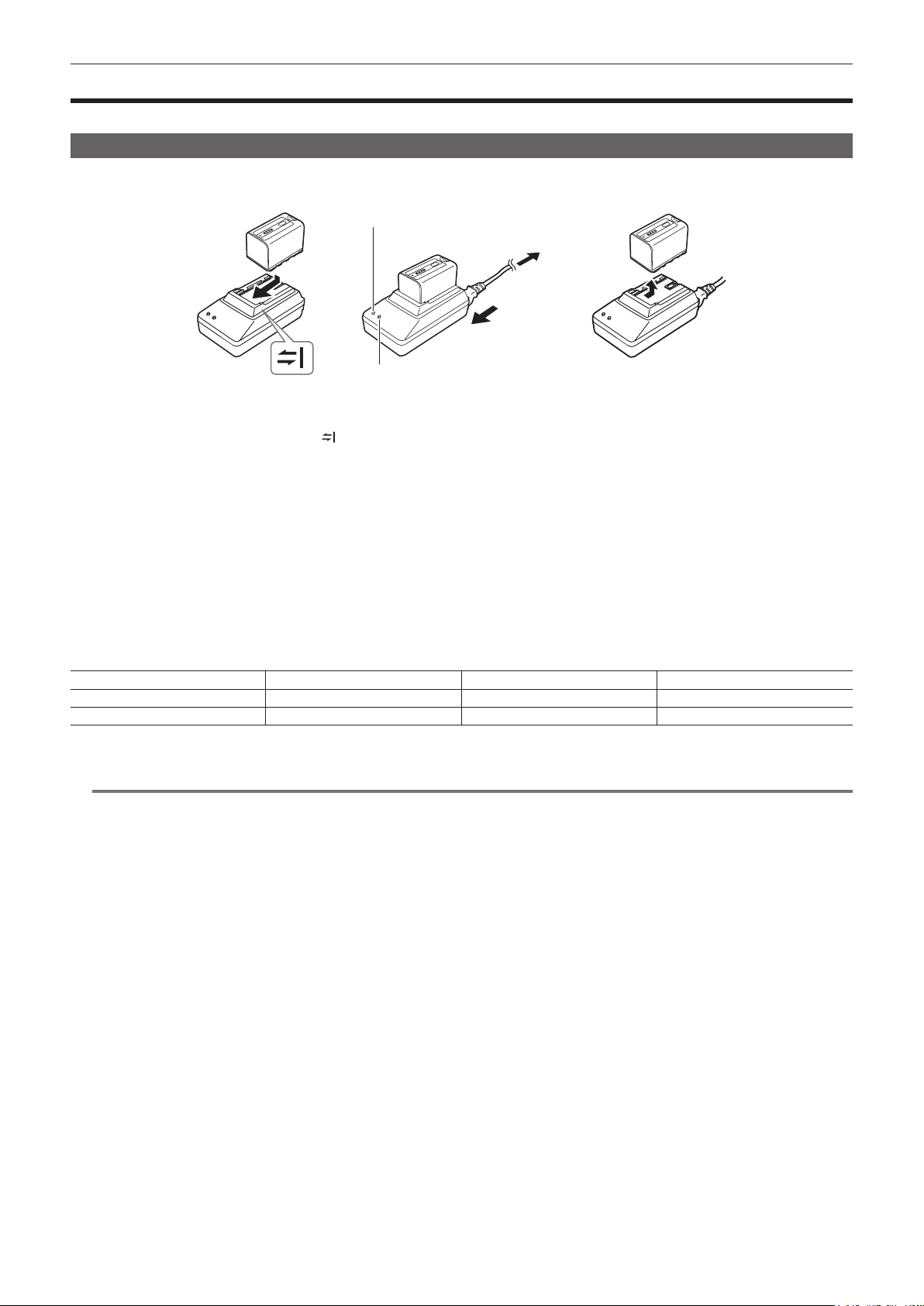
Charging the battery
The battery is not charged at the time of purchase. Fully charge the battery in the battery charger before using the battery.
It is recommended that you have one extra battery.
<POWER> lamp
To the power outlet
(2)
(1)
<CHARGE> lamp
Fig. 1 Fig. 2 Fig. 3
Place the battery horizontally along the mark in the battery charger and slide it in. (Fig. 1)
1
Press it in rmly.
Connect an AC cable. (Fig. 2)
2
Connect in the order shown in the gure.
f <POWER> lamp
- Once the AC cable is connected, the lamp will light up.
f <CHARGE> lamp
- Lit: Charging.
- Not lit: Charging is complete.
- Flashing: Reinsert the battery.
Slide the battery out to remove it. (Fig. 3)
3
r Standard charging time and recording time
Battery parts number Voltage/capacity Charging time Continuous shootable time
VW-VBD58 (supplied) 7.2 V/5800 mAh Approx. 380 min Approx. 90 min
CGA-D54/CGA-D54s (optional) 7.2 V/5400 mAh Approx. 330 min Approx. 85 min
f The time when the ambient operating temperature is 20°C and the relative operating humidity is 60%. At other temperature and humidity the charging
time may take longer.
NOTE
@@
t Continuous recordable time is applied under the following conditions. If you use the camera in other conditions, continuous shootable time will shorten.
- With the LCD monitor open
- When the main menu → [OUTPUT SEL] → [SDI OUT] is set to [OFF]
- When the main menu → [OUTPUT SEL] → [VIDEO OUT] is set to [OFF]
- With the cable not inserted into the <HDMI OUT> terminal
t The battery and camera recorder will become warm during use or while charging.
t Make sure that batteries are discharged before storing them.
t When stored for long periods of time, it is recommended that you charge batteries once per year and then use up the battery capacity by using the
battery in the camera recorder before storing it again.
t When the battery becomes extremely hot or cold, the <CHARGE> lamp will ash several times and charging will automatically begin.
t When the battery is left unused and discharged for a long time, the <CHARGE> lamp will ash several times and charging will automatically begin.
t If the <CHARGE> lamp continues blinking even when the battery is at its optimal temperature, the battery or battery charger may be damaged.
Contact a dealer.
t If the battery is warm, it will take longer than usual to charge.
t If you use the battery charger near a radio, the radio sound may be distorted. Keep the battery and battery charger at least 1 m away from radios
when in use.
t Noise may be emitted from the battery charger when using the battery charger, but this does not indicate a malfunction.
r Supplied battery
f Remaining battery level display function
The approximate remaining battery level can be checked by looking at the LED display of the battery.
The displayed battery level may be different when the battery is attached to the camera and you are shooting and when the battery is not attached.
f The supplied battery is intended for use only in this camera.
Do not use it in other devices.
– 25 –
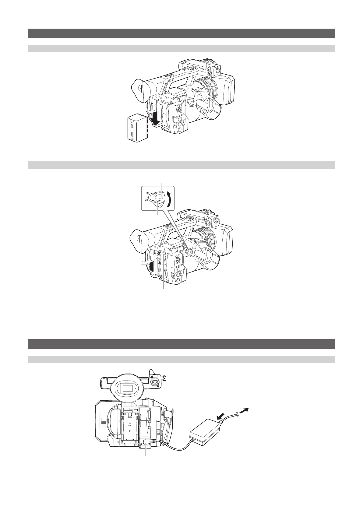
Attaching and removing the battery
Attaching
Insert the battery until you hear it clicks.
1
Removing
Chapter 3 Preparation — Power supply
Lock release button
Power switch
Battery release button
Turn the power switch to <OFF> while holding down the lock release button.
1
Make sure that the LCD monitor has gone off.
Lift up and remove the battery while holding down the battery release button.
2
Support the battery with your hand so that it does not fall down.
Using the AC adaptor
Attaching
Connect an AC cable.
1
Connect in the order shown in the gure.
<DC IN 12V> terminal
– 26 –
To the power outlet
(1)
(2)

Chapter 3 Preparation — Power supply
Connect the AC adaptor to the <DC IN 12V> terminal.
2
Removing
Turn the power switch to <OFF> while holding down the lock release button.
1
Make sure that the LCD monitor has gone off.
Remove the AC adaptor from the <DC IN 12V> terminal.
2
NOTE
@@
t When not using the camera, remove the AC cable from the power outlet.
t Use the supplied AC adaptor. Do not use other AC adaptors.
t The AC adaptor can be connected when attaching the battery to the camera. When the AC adaptor is connected, the camera will switch to be powered
by the AC adaptor. When removing the AC adaptor, the camera will be powered by the battery.
– 27 –
Chapter 3 Preparation — Attaching and adjusting accessories
Attaching and adjusting accessories
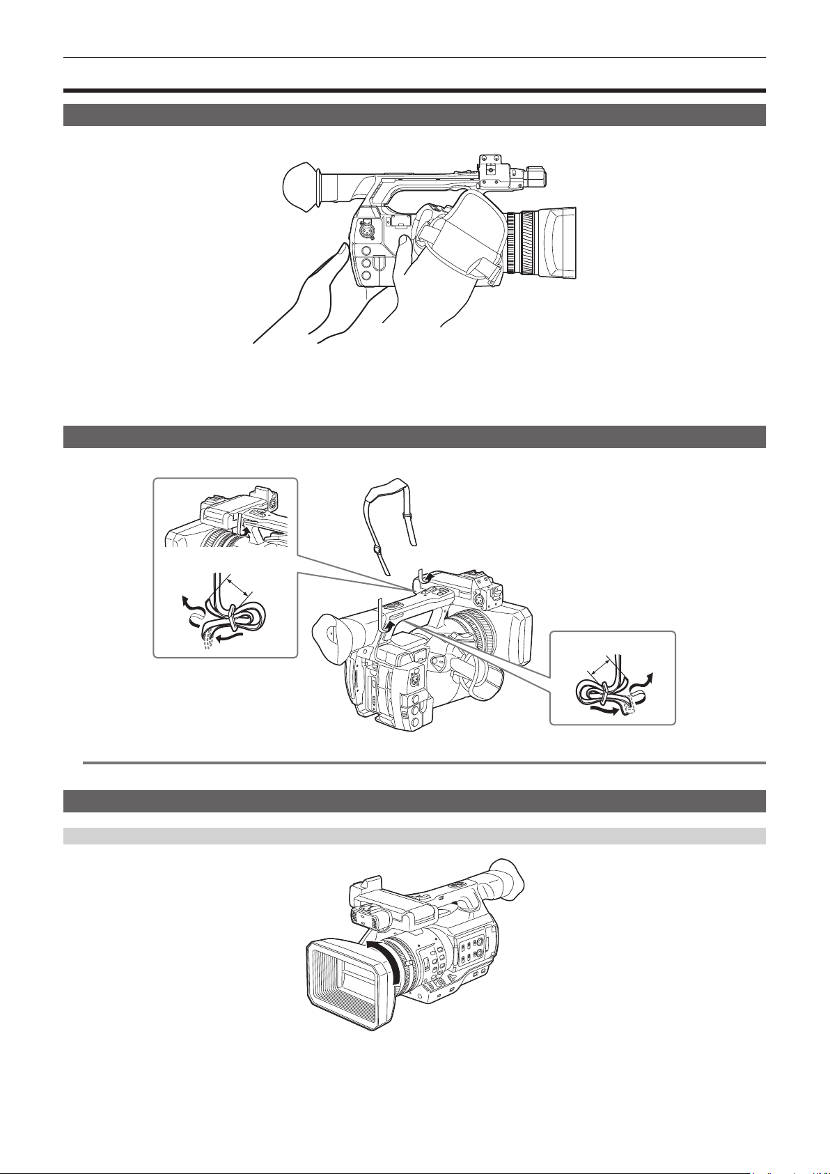
Adjusting the grip strap
Adjust the grip strap so that it ts the size of your hand.
Open the cover and adjust the length of the strap.
1
Replace the cover.
2
Attach the cover rmly.
Attaching the shoulder strap
Attach the shoulder strap to the attachment lugs.
Longer than 20 mm
NOTE
@@
t Make sure that the shoulder strap is securely attached.
Attaching the lens hood
Removing
Longer than 20 mm
Rotate the lens hood counter-clockwise.
1
– 28 –
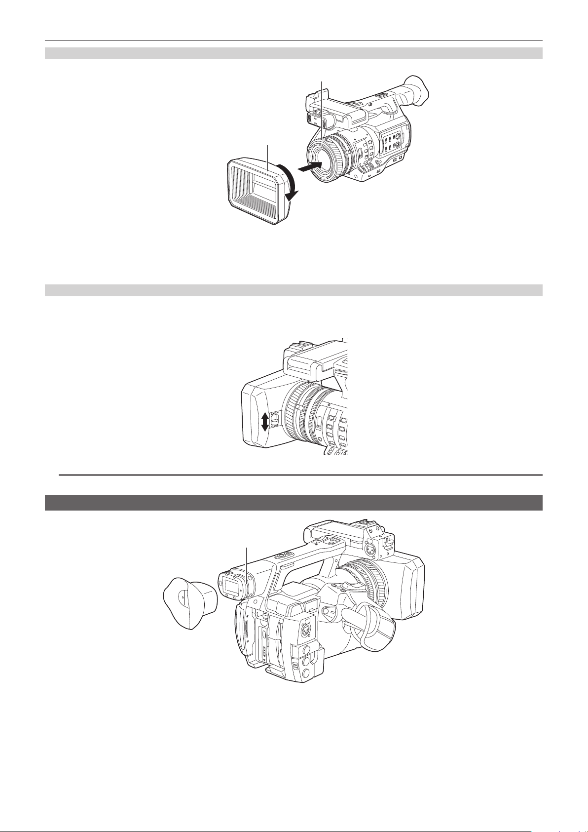
Chapter 3 Preparation — Attaching and adjusting accessories
Attaching
Center of camera
The side with the index of the lens hood
Align the index of the lens hood with the center of the camera body and attach.
1
Position the lens hood so that the side with the index of the lens hood is facing upwards.
Rotate the lens hood clockwise until it locks in with a click.
2
Opening and closing the lens cover
Use the lens cover open/close lever to open and close the lens cover.
Open the lens cover to take videos and photographs.
When not using the camera, close the lens cover in order to protect the lens.
NOTE
@@
t Do not press the lens cover with force. Doing so may damage the lens and lens cover.
Attaching the eye cup
Groove
Attach the eye cup by aligning the groove on the attaching part of the eye cup with the inner ridge of the eye cup.
1
– 29 –
Chapter 3 Preparation — Attaching and adjusting accessories
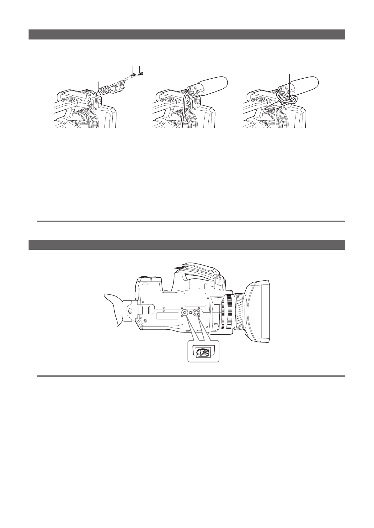
Attaching the front microphone
Microphones such as a super-directional microphone AG-MC200G (optional) can be attached.
Screws for tapped hole protection are attached on the camera body. Remove those screws when you attach the microphone holder.
Screw for the microphone holder
Microphone cable clamp
Microphone holder
<AUDIO INPUT 1> terminal
Fig. 3Fig. 2Fig. 1
Attach the microphone holder. (Fig. 1)
1
Attach the microphone and tighten the microphone holder clamping screw. (Fig. 2)
2
Connect the microphone connecting cable to the <AUDIO INPUT 1> terminal on the camera. (Fig. 3)
3
Secure the microphone connecting cable with the microphone cable clamp.
4
Set the <INPUT 1> switch to match the microphone to be connected.
5
NOTE
@@
t The microphone holder cannot be xed with the screws originally attached on the camera. Use the dedicated screws that came with the camera to x
the microphone holder.
Attaching a tripod
The tripod attachment holes accept 1/4-20 UNC and 3/8-16 UNC screws. Use the hole that matches the diameter of the clamping screw on the tripod.
NOTE
@@
t Use a tripod in safe locations.
t The depth of the tripod attachment hole is 5.5 mm. When attaching the camera to a tripod, do not over-tighten the tripod screw.
– 30 –
 Loading...