

Page 1

Operating Instructions
Memory Card Portable Recorder
ModelNo.AJ-PG50
Before operating this product, please read the instructions carefully and save this manual for future use.
W1214TO0 -PS
ENGLISH
VQT5L34A (E)
Page 2

Read this first!
CAUTION:
Danger of explosion or fire if battery is incorrectly
replaced or mistreated.
• Do not disassemble the battery or dispose of it in
fire.
• Do not store in temperatures over 60 °C (140 °F).
• Do not expose the battery to excessive heat such
as sunshine, fire or the like.
For Battery Pack
• Use specified charger.
• Replace only with same or specified type.
CAUTION:
In order to maintain adequate ventilation, do not
install or place this unit in a bookcase, built-in
cabinet or any other confined space. To prevent risk
of electric shock or fire hazard due to overheating,
ensure that curtains and any other materials do not
obstruct the ventilation.
WARNING:
• To reduce the risk of fire or electric shock, do not
expose this equipment to rain or moisture.
• To reduce the risk of fire or electric shock, keep
this equipment away from all liquids. Use and
store only in locations which are not exposed to
the risk of dripping or splashing liquids, and do not
place any liquid containers on top of the
equipment.
WARNING:
Always keep memory cards (optional accessory)
out of the reach of babies and small children.
CAUTION:
The mains plug of the power supply cord shall
remain readily operable.
The AC receptacle (mains socket outlet) shall be
installed near the equipment and shall be easily
accessible.
To completely disconnect this equipment from the
AC mains, disconnect the mains plug from the AC
receptacle.
CAUTION:
To reduce the risk of fire or electric shock and
annoying interference, use the recommended
accessories only.
CAUTION (For USA and Canada):
This apparatus can be operated at a voltage in the
range of 100 – 240 V AC.
Voltages other than 120 V are not intended for
U.S.A. and Canada.
Operation at a voltage other than 120 V AC may
require the use of a different AC plug. Please
contact either a local or foreign Panasonic
authorized service center for assistance in selecting
an alternate AC plug.
CAUTION:
Excessive sound pressure from earphones and
headphones can cause hearing loss.
CAUTION:
Do not leave the unit in direct contact with the skin
for long periods of time when in use.
Low temperature burn injuries may be suffered if
the high temperature parts of this unit are in direct
contact with the skin for long periods of time.
When using the equipment for long periods of time,
make use of the tripod.
indicates safety information.
Read this first!:
2
CAUTION (For USA and Canada):
To prevent electric shock, match wide blade of plug
to wide slot, fully insert.
Page 3
Read this first! (continued)
FCC NOTICE (U.S.A.)
Declaration of Conformity
Model Number: AJ-PG50
Trade Name: Panasonic
Responsible Party: Panasonic Corporation of North America
Two Riverfront Plaza, Newark, NJ 07102
Support contact: 1-800-524-1448
This device complies with Part 15 of the FCC Rules.
Operation is subject to the following two conditions:
(1) This device may not cause harmful interference, and (2) this device must accept any interference received, including
interference that may cause undesired operation.
To assure continued compliance, follow the attached installation instructions and do not make any unauthorized
modifications.
CAUTION:
This equipment has been tested and found to comply with the limits for a Class B digital device, pursuant to Part 15 of the
FCC Rules. These limits are designed to provide reasonable protection against harmful interference in a residential
installation. This equipment generates, uses and can radiate radio frequency energy and, if not installed and used in
accordance with the instructions, may cause harmful interference to radio communications. However, there is no
guarantee that interference will not occur in a particular installation. If this equipment does cause harmful interference to
radio or television reception, which can be determined by turning the equipment off and on, the user is encouraged to try
to correct the interference by one or more of the following measures:
• Reorient or relocate the receiving antenna.
• Increase the separation between the equipment and receiver.
• Connect the equipment into an outlet on a circuit different from that to which the receiver is connected.
• Consult the dealer or an experienced radio/TV technician for help.
The user may find the booklet “Something About Interference” available from FCC local regional offices helpful.
FCC Warning:
To assure continued FCC emission limit compliance, follow the attached installation instructions and the user must use
only shielded interface cables when connecting to host computer or peripheral devices. Also any unauthorized changes or
modifications to this equipment could void the user’s authority to operate this device.
Read this first!
NOTIFICATION (Canada)
CAN ICES-3 (B)/NMB-3(B)
indicates safety information.
For USA
A lithium ion/polymer battery that is recyclable powers the product you have purchased. Please call 1-800-8-BATTERY for information on how to recycle this battery.
Notice (U.S.A. only):
Disposal may be regulated in your community due to Environmental considerations. For disposal or recycling information,
please visit Panasonic website: http://www.panasonic.com/environmental or call 1-888-769-0149.
Note:
The rating plate is on the underside of the Recorder, Battery Charger and AC Adaptor.
For Turkey
EEE Yönetmeliğine Uygundur.
EEE Complies with Directive of Turkey.
Read this first!:
3
Page 4

Read this first! (continued)
IMPORTANT SAFETY INSTRUCTIONS
1) Read these instructions.
2) Keep these instructions.
3) Heed all warnings.
4) Follow all instructions.
5) Do not use this apparatus near water.
6) Clean only with dry cloth.
7) Do not block any ventilation openings. Install in accordance with the manufacturer’s instructions.
8) Do not install near any heat sources such as radiators, heat registers, stoves, or other apparatus (including amplifiers) that
produce heat.
9) Do not defeat the safety purpose of the polarized or grounding-type plug. A polarized plug has two blades with one wider than
the other. A grounding-type plug has two blades and a third grounding prong. The wide blade or the third prong are provided
for your safety. If the provided plug does not fit into your outlet, consult an electrician for replacement of the obsolete outlet.
10) Protect the power cord from being walked on or pinched particularly at plugs, convenience receptacles, and the point where
they exit from the apparatus.
11) Only use attachments/accessories specified by the manufacturer.
12) Use only with the cart, stand, tripod, bracket, or table specified by the manufacturer, or sold with the apparatus.
When a cart is used, use caution when moving the cart/apparatus combination to avoid injury from tip-over.
13) Unplug this apparatus during lightning storms or when unused for long periods of time.
14) Refer all servicing to qualified service personnel. Servicing is required when the apparatus has been damaged
in any way, such as power-supply cord or plug is damaged, liquid has been spilled or objects have fallen into
the apparatus, the apparatus has been exposed to rain or moisture, does not operate normally, or has been dropped.
S3125A
Декларація про Відповідність
Вимогам Технічного Регламенту Обмеження Використання деяких Небезпечних Речовин в електричному та
електронному обладнанні
(затвердженого Постановою №1057 Кабінету Міністрів України)
Виріб відповідає вимогам Технічного Регламенту Обмеження Використання деяких Небезпечних Речовин в
елек тричному
Вміст небезпечних речовин у випадках, не обумовлених в Додатку №2 ТР ОВНР, :
1. свинець(Pb) – не перевищує 0,1 % ваги речовини або в концентрації до 1000 частин на мільйон;
2. кадмій (Cd)– не перевищує 0,01 % ваги речовини або в концентрації до 100 частин на мільйон;
3. ртуть(Hg) – не перевищує 0,1 % ваги речовини або в концентрації
4. шестивалентний хром (Cr6+ ) – не перевищує 0,1 % ваги речовини або в концентрації до 1000 частин на мільйон;
5. полібромбіфеноли (PBB) – не перевищує 0,1% ваги речовини або в концентрації до 1000 частин на мільйон;
6. полібромдефенілові ефіри (PBDE) – не перевищує 0,1 % ваги речовини або в концентрації до 1000 частин на
мільйон.
та електронному обладнанні (ТР ОВНР).
до 1000 частин на мільйон;
Read this first!:
4
Page 5
Read this first! (continued)
Caution for AC Mains Lead
FOR YOUR SAFETY PLEASE READ THE FOLLOWING TEXT CAREFULLY.
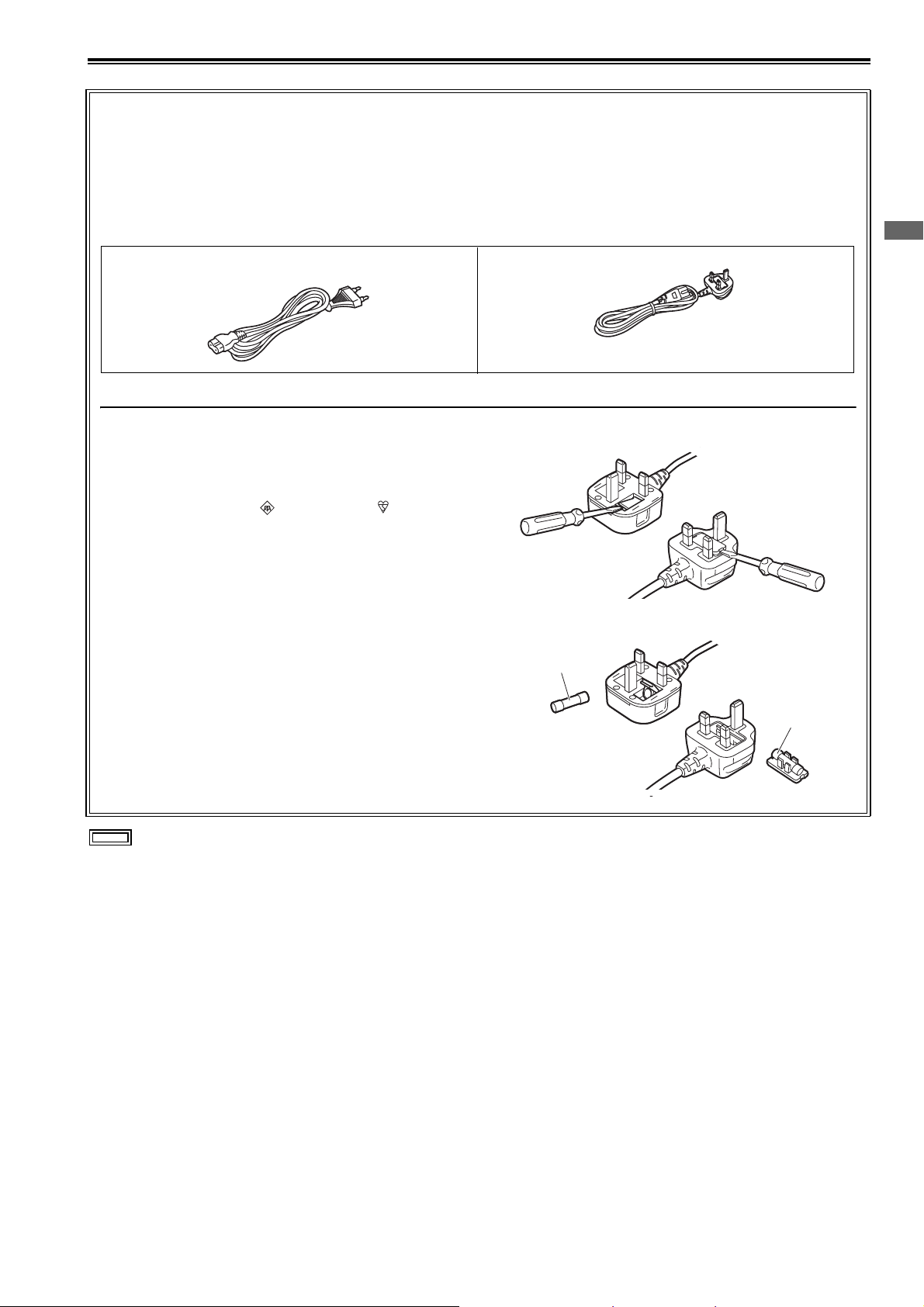
This product is equipped with 2 types of AC mains cable. One is for continental Europe, etc. and the other one is for U.K.
Appropriate mains cable must be used in each local area, since the other type of mains cable isnot suitable.
FOR CONTINENTAL EUROPE, ETC.
Not to be used in the U.K.
FOR U.K. ONLY
This appliance is supplied with a moulded three pin mains
plug for your safety and convenience.
A 5 amp fuse is fitted in this plug.
Should the fuse need to be replaced please ensure that the
replacement fuse has a rating of 5 amps and that it is
approved by ASTA or BSI to BS1362.
Check for the ASTA mark or the BSI mark on the body
of the fuse.
If the plug contains a removable fuse cover you must ensure
that it is refitted when the fuse is replaced.
If you lose the fuse cover the plug must not be used until a
replacement cover is obtained.
A replacement fuse cover can be purchased from your local
Panasonic Dealer.
FOR U.K.
How to replace the fuse
1. Open the fuse compartment with a screwdriver.
or
2. Replace the fuse
Fuse
Read this first!
indicates safety information.
or
Fuse
Read this first!:
5
Page 6

Read this first! (continued)
EMC NOTICE FOR THE PURCHASER/USER OF THE APPARATUS
1. Applicable standards and operating environment (AJ-PG50)
The apparatus is compliant with:
• standards EN55103-1 and EN55103-2, and
• electromagnetic environments E1, E2, E3 and E4
2. Pre-requisite conditions to achieving compliance with the above standards
<1> Peripheral equipment to be connected to the apparatus and special connecting cables
• The purchaser/user is urged to use only equipment which has been recommended by us as
peripheral equipment to be connected to the apparatus.
• The purchaser/user is urged to use only the connecting cables described below.
<2> For the connecting cables, use shielded cables which suit the intended purpose of the
apparatus.
• Video signal connecting cables
Use double shielded coaxial cables, which are designed for 75-ohm type high-frequency applications,
for SDI (Serial Digital Interface).
Coaxial cables, which are designed for 75-ohm type high-frequency applications, are recommended
for analog video signals.
• Audio signal connecting cables
If your apparatus supports AES/EBU serial digital audio signals, use cables designed for AES/EBU.
Use shielded cables, which provide quality performance for high-frequency transmission applications,
for analog audio signals.
• Other connecting cables
Use shielded cables, which provide quality performance for high-frequency applications, such as
connecting cables for IEEE1394 or USB.
• When connecting to the HDMI signal terminal, use multilayer shielded cables, which provide quality
performance for high-frequency applications.
• When connecting to the DVI signal terminal, use a cable with a ferrite core.
• If your apparatus is supplied with ferrite core(s), they must be attached on cable(s) following
instructions in this manual.
3. Performance level
The performance level of the apparatus is equivalent to or better than the performance level required by
these standards.
However, the apparatus may be adversely affected by interference if it is being used in an EMC environment,
such as an area where strong electromagnetic fields are generated (by the presence of signal transmission
towers, cellular phones, etc.). In order to minimize the adverse effects of the interference on the apparatus in
cases like this, it is recommended that the following steps be taken with the apparatus being affected and
with its operating environment:
1. Place the apparatus at a distance from the source of the interference.
2. Change the direction of the apparatus.
3. Change the connection method used for the apparatus.
4. Connect the apparatus to another power outlet where the power is not shared by any other
appliances.
Manufactured by: Panasonic Corporation, Osaka, Japan
Importer’s name and address of pursuant to EU rules:
Panasonic Marketing Europe GmbH
Panasonic Testing Centre
Winsbergring 15, 22525 Hamburg, Germany
Read this first!:
6
Page 7
Read this first! (continued)
Batteries that may be used with this product (Correct as of March 2014)
Panasonic VW-VBD58 batteries may be used with this product.
It has been found that counterfeit battery packs which look very similar to the genuine product are made available to
purchase in some markets. Some of these battery packs are not adequately protected with internal protection to meet the
requirements of appropriate safety standards. There is a possibility that these battery packs may lead to fire or explosion.
Please be advised that we are not liable for any accident or failure occurring as a result of use of a counterfeit battery pack.
To ensure that safe products are used we would recommend that a genuine Panasonic battery pack is used.
Battery Charger / AC Adaptor
Disconnect the AC mains plug from the AC mains socket when not in use.
Note regarding the Power Management function specified under COMMISSION REGULATION (EC)
No 1275/2008 implementing Directive 2009/125/EC of the European Parliament and of the Council.
This device is designed and manufactured for use at a broadcasting station and/or in a similar environment.
This device is not equipped with a Power Management function or the Power Management function is set to OFF as it will
prevent the device from fulfilling its intended purpose for the reasons below.
1. If the device is a Studio Camera, a Weather Camera, a Mixer or other processor:
A Power Management function may cause the device to suddenly stop during recording or while On Air.
2. If the device is a Studio Monitor:
A Power Management function may cause video for the confirmation of whether a signal is normal, or whether the signal
has been lost, to be un-viewable.
3. If the device is a Camera Recorder:
A professional camera recorder must be able to start quickly at any time, but a Power Management function will cause an
increase in the time taken to resume from Stand-by mode.
Read this first!
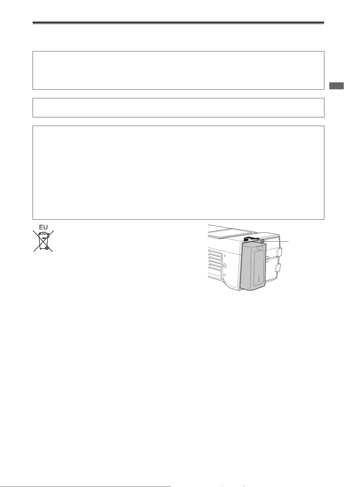
To remove the battery
Main Power Battery
Press the battery release button.
Back-up Battery
• For the removal of the battery for disposal at the end of its service life,
please consult your dealer.
Battery
release button
Read this first!:
7
Page 8
Read this first! (continued)
Brazil Only
Brasil Apenas
■ Manuseio de baterias usadas
Cobrir os terminais positivo (+) e negativo (-) com uma fita isolante adesiva, antes de depositar numa caixa destinada para
o recolhimento. O contato entre partes metálicas pode causar vazamentos, gerar calor, romper a blindagem e produzir fogo.
Não desmonte, não remova o invólucro, nem amasse a bateria. O gás liberado pela bateria pode irritar a garganta, danificar
o lacre do invólucro ou o vazamento provocar calor, ruptura da blindagem e produzir fogo devido ao curto circuito dos ter-
minais.
Não incinere nem aqueça as baterias, elas não podem ficar expostas a temperaturas superiores a 100 °C (212 °F). O gás
liberado pela bateria pode irritar a garganta,danificar o lacre do invólucro ou o vazamento provocar calor, ruptura da blind-
agem e produzir fogo devido ao curto circuito dos terminais provocado internamente.
Evite o contato com o liquido que vazar das baterias. Caso isto ocorra, lave bem a parte afetada com bastante água. Caso
haja irritação, consulte um médico.
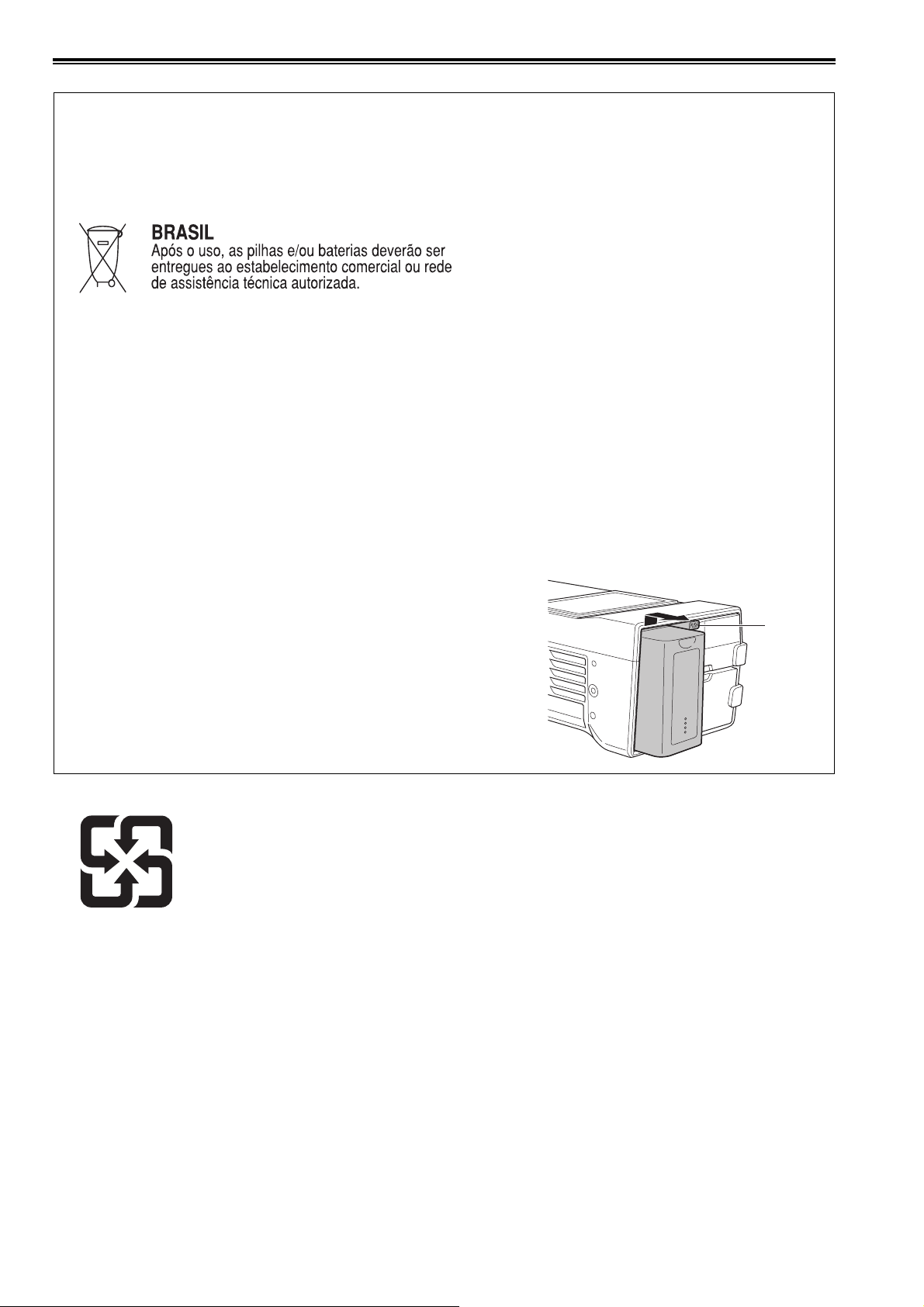
■ Para remover a bateria
Bateria Principal de Energia
Pressione o botão para liberar a bateria.
This symbol in only valid in TAIWAN.
廢電池請回收
Botão de
liberação
da bateria
Read this first!:
8
Page 9

• The SDXC logo is a trademark of SD-3C, LLC.
• HDMI, the HDMI logo, and High-Definition Multimedia Interface are trademarks or registered trademarks of HDMI Licensing
LLC in the United States and/or other countries.
•Microsoft
®
and Windows® are registered trademarks or trademarks of Microsoft Corporation in the United States and/or other
countries.
• QuickTime and the QuickTime logo are trademarks or registered trademarks of Apple Inc., used under license therefrom.
• Apple, Mac, Mac OS, MacBook, iPhone, iPod touch, iPad, QuickTime, and Safari are registered trademarks of Apple Inc. in
the United States and/or other countries.
• Microsoft product screenshots are used in accordance with the guidelines of Microsoft Corporation.
• Other company names and product names appearing in this manual are trademarks or registered trademarks of their respective owners.
Illustrations in this manual
• Illustrations of the recorder unit and menu screens may appear different from the actual recorder unit and menu screens.
Page references
• In this manual, page references are indicated as: (➝ “½½½” page ½½).
Terminology
• An SD memory card, SDHC memory card, and SDXC memory card are all referred to as an “SD memory card.”
• A memory card with the “P2” logo (for example, the separately sold AJ-P2E064FG) is referred to as a “P2 memory card.”
• A memory card with the “microP2” logo (for example, the separately sold AJ-P2M032AG) is referred to as a “microP2 memory
card.”
• A P2 memory card and microP2 memory card are referred to as a “P2 card.”
Furthermore, a P2 memory card slot and microP2 memory card slot are referred to as a “P2 card slot.”
• Recording with the system frequency at 23.98 Hz or 24 Hz is referred to as “native recording.”
• In this manual, the following operating system is referred to as “Windows 7.”
- Microsoft
®
Windows® 7 operating system
• In this manual, the following operating system is referred to as “Windows 8.”
- Microsoft
®
Windows® 8 operating system
• A recordable media device such as an external hard disk drive connected to a USB port is referred to as a “storage device.”
• Video created by a single recording operation is referred to as a “clip.”
• Orange button labels on the unit panel indicate alternate functions enabled by holding down the [SHIFT] button. The operating
instructions refer to the buttons only by label, without mentioning the [SHIFT] button.
Proxy recording with this product
This product is licensed under the AVC Patent Portfolio license for personal and non-commercial use, and is not licensed for
any activity except those for personal use described below.
• Recording video compliant with the AVC standard (hereinafter referred to as an AVC video).
• Playing AVC video recorded by a consumer engaged in a personal and non-commercial activity.
• Playing AVC video that was obtained from a licensed provider.
For details, refer to the MPEG LA, LLC website (http://www.mpegla.com).
Website URL
http://pro-av.panasonic.net/
About copyrights
• Copyright laws may prohibit use, except for personal pleasure, of your recorded video and audio content without permission
of the rights holder.
9
Page 10

Contents
Read this first!................................................. 2
Usage Precautions ........................................ 11
Regarding this unit ............................................. 11
AC adaptor ......................................................... 12
Battery ................................................................ 13
Battery characteristics .............................................. 13
Remove the battery after use ................................... 13
Take proper care of the battery terminal .................. 13
Before Use ......................................................... 13
Setting the Area of Use (Frame Frequency and
Other Settings) .................................................... 13
Always confirm the year, month, day, time, and
time zone, and set as necessary ........................ 13
Compatible storage media ....................................... 13
Driver installation ...................................................... 14
Accessories .............................................................. 14
Optional Accessories ............................................... 14
Control Reference Guide............................... 15
Controls .............................................................. 15
Slots and I/O Controls ........................................ 17
I/O Connectors and Power Components ........... 19
Preparation .................................................... 21
Power Supply ..................................................... 21
Charging the Battery ................................................ 21
Using the Battery ................................................ 22
Installation ................................................................. 22
Removal .................................................................... 22
Using the AC Adaptor ........................................ 23
Installation ................................................................. 23
Removal .................................................................23
How to Turn On/Off the Power ........................... 24
Turning On the Power ............................................... 24
Turning Off the Power ............................................... 24
Auto Power Off during Operation ............................. 24
Setting the Year, Month, Day, and Time ............ 25
P2 Cards ............................................................ 26
P2 Card Access Lamp and P2 Card Status ............. 26
P2 Card Recording Times ........................................ 26
Handling of Recording Data ............................... 28
Using SD/SDHC/SDXC Memory Cards ............. 29
Available Modes ............................................ 30
Main Mode ..................................................... 31
Recording/Playback Screen ............................... 31
Recording Clips ........................................................ 31
Playing Back Clips .................................................... 34
Thumbnail Screen .............................................. 37
Displaying the Thumbnail Screen ............................. 37
Names and Functions of the Parts of the Thumbnail
Screen ................................................................ 38
Changing the Thumbnail Display ............................. 40
Playing Back Clips .................................................... 41
Selecting and Deselecting Clips .............................. 43
Adding Text Memos and Shot Marks ....................... 43
Copying Clips ........................................................... 44
Deleting Clips ........................................................... 45
Repairing and Reconnecting Clips .......................... 45
Viewing and Editing the Clip Information ................. 46
Changing Thumbnails .............................................. 47
Adding Metadata to Clips During Recording ........... 48
Formatting P2 Cards and SD Memory Cards .......... 50
Checking the Card Status ........................................ 50
Manual and Automatic CPS Authentication ............. 51
Connecting an External Device via the USB HOST
Port ..................................................................... 53
Using the Unit Connected to a Network ..............61
Network Connection ................................................. 61
Preparing for Connection ......................................... 62
Network Settings ...................................................... 63
Network Functions .................................................... 67
Network Settings ...................................................... 68
Using FTP Client Functions ...................................... 69
Viewing the Thumbnails of Clips on an FTP Server
(FTP Thumbnail Screen) ..................................... 70
Deleting Clips on the FTP Server ............................. 71
Viewing FTP Server Clip Information ........................ 71
Transferring Clips ..................................................... 71
Transferring SD Memory Card Data ......................... 73
USB Device Mode ......................................... 75
P2 Playlist Editing Mode................................ 76
Screen Display............................................... 78
OSD Display ....................................................... 78
Deck Information (DIAG) Display ........................80
Waveform Monitor (WFM) Display ......................80
Time Code, User Bits, and CTL..................... 81
Time code ................................................................ 81
User Bits ................................................................... 81
CTL ........................................................................... 81
Setting the Time Code and User Bits ....................... 81
Setup Menu ................................................... 83
Menu Operations ................................................ 83
Menu Structure ................................................... 84
Menu List ............................................................ 86
CLIP .......................................................................... 86
REC/PB ..................................................................... 90
I/F SETUP ................................................................. 95
FILE ........................................................................ 103
SYSTEM .................................................................. 106
List of Compatible Input and Output Formats ........ 108
Using a Keyboard ........................................ 109
Full Keyboard ......................................................... 109
Numeric Keyboard ................................................. 109
USB Keyboard ....................................................... 109
For Long and Trouble-Free Operation......... 110
Maintenance ..................................................... 110
Condensation .................................................... 110
Storage Precautions .........................................110
Warning System ...............................................111
Warning Details ...................................................... 111
Error Codes ............................................................ 112
Updating the Firmware in This Unit ........................ 119
Specifications............................................... 120
Index ............................................................ 124
10
Page 11

Usage Precautions
Regarding this unit
Panasonic makes no guarantees regarding re-
cordings
• Please note that Panasonic makes no guarantees regarding
recordings in cases where images and/or audio were not recorded as you intended due to problems with this unit or P2
cards.
Be careful to avoid getting water inside the unit
when using it in rainy or snowy weather, or near
the sea shore.
• The unit or a card may be damaged. (In some cases, it may
become unrepairable.)
Do not install this unit in a location exposed to
direct sunlight.
• The cabinet may be deformed and the LCD screen may be
damaged.
Keep the unit away from electromagnetic devic-
es (such as TVs and video game consoles).
• Using the unit on or near a TV may result in distorted images
or audio due to electromagnetic radiation.
• The strong magnetic field produced by loudspeakers and
large monitors may damage recordings or distort images.
• Electromagnetic waves from microcomputers may
adversely affect the unit or distort images and audio.
• If an electromagnetic device adversely affects the unit and
results in it becoming unable to be operated correctly, turn
the unit off and disconnect the AC cable from the outlet.
Then, reconnect the AC cable. Finally, turn the unit back on.
Do not use the unit near a radio transmitter or
high-voltage equipment.
• Use near a radio transmitter or high-voltage equipment may
adversely affect recorded images and audio.
When using the unit at the sea shore, in the open
air, etc., be careful not to get sand or dust inside.
• The sand or dust may damage the unit or a card. (Be especially careful when inserting and removing cards.)
When carrying the unit, be careful not to drop it.
• A strong impact may damage the unit and result in it becoming unable to be operated correctly.
Do not get insecticides or other volatile materi-
als on the unit.
• The unit may be deformed and the paint may peel off if insecticides or other volatile materials get on the unit.
• Do not leave the unit in contact with rubber or vinyl products
for long periods.
Notes on the disposal or transfer of memory
cards and storage devices
The format and delete functions on this unit or a computer will
only change the file management data and will leave the data
on the memory card or storage device intact. It is recommended that cards or storage devices either be physically destroyed or that commercially available software be used to
completely delete any data they contain. Management of data
on memory cards and storage devices is the sole responsibility of the user.
LCD
• The pixels of the LCD monitor are controlled to obtain high
precision with 99.99% of the effective pixels. This leaves
less than 0.01% of pixels that may not light or may remain
on all the time. This is normal and will have no effect on the
images you shoot.
• There may be some unevenness on the screen depending
on the image displayed.
• Wiping or rubbing the LCD screen with a rough cloth may
damage it.
• A temporary afterimage (burn-in) may occur when the same
image or text is displayed for a long time, although it can be
recovered by turning the power off for several hours.
• LCD response and brightness vary with operating temperature.
• In a high-temperature and high-humidity location, the LCD
panel characteristics may change and result in uneven image quality.
• If an unsupported signal is input to the unit for a long period
of time, the LCD panel characteristics may change and result in uneven image quality.
Notes on using the network function
Please note that Panasonic makes no guarantees regarding
damage resulting from incorrectly configuring the network
settings to use the network function. Furthermore, please also
note that Panasonic is not liable to pay compensation for any
damages arising from the use of this function.
Usage Precautions
Usage Precautions: Regarding this unit
11
Page 12

Notes on security
If you use the network function of this product, there is the likelihood of being subjected to the following damage.
• Leakage of personal information via this product
• Unauthorized operation of this product by a third party with
malicious intent
• Interference or stoppage of this product by a third party with
malicious intent
Be sure to implement sufficient security measures for computers and mobile devices.
• Set a password to limit the users who can log in.
• Use a password that is as difficult to guess as possible.
• Change the password regularly.
• Panasonic and its affiliate companies would never directly
inquire about a password. In the event that somebody does
make a direct inquiry, do not let the person know the password.
• Prior to the repair, maintenance, disposal, or transfer of this
product, initialize the network settings to prevent the leakage of information.
Information on software for this product
1. This product includes software licensed under the GNU General Public License (GPL) and GNU Lesser General Public License (LGPL), and users are hereby informed that they have the right to obtain, modify, and redistribute the source code
of this software.
2. This product includes software licensed under the MIT-License.
3. This product includes software developed by the OpenSSL Project for use in the OpenSSL Toolkit (http://www.openssl.org/).
4. This product includes software licensed under the OpenBSD License.
5. This product includes PHP, freely available from <http://www.php.net/>.
6. This software is based in part on the work of the Independent JPEG Group.
7. This product includes software licensed under the MOZILLA PUBLIC LICENSE.
To see the details (in the original (English-language) text) and obtain the source code, visit the following website. (➝ “Web-
site URL” on page 9)
Users are requested to refrain from making any inquiries about the source code they have obtained.
AC adaptor
Use the supplied AC adaptor. Read the Operating Instructions (➝ “Using the AC Adaptor” page 23) before use.
Usage Precautions: AC adaptor
12
Page 13

Battery
Battery characteristics
This unit uses a rechargeable lithium-ion battery that uses its internal chemical reaction to generate electrical energy. This reaction is easily influenced by the ambient temperature and humidity, and the battery’s effective operating time is reduced as
the temperature rises or falls. In very low temperatures, the battery may last only 5 minutes.
Protective circuitry functions if you use the battery where it is very hot and you will have to wait before you can use it again.
Remove the battery after use
Completely remove the battery. (The battery continues to be used even if you have turned the unit off.)
The battery can over discharge if you leave it in the unit and it may become impossible to recharge it.
Take proper care of the battery terminal
Do not allow dust or foreign objects on the battery terminal.
Also, if you drop the battery by mistake, make sure that the battery body and the terminal are not warped.
Inserting a deformed battery into the unit or attaching it to the battery charger may cause damages on the unit or battery charger.
Usage Precautions
Before Use
Setting the Area of Use (Frame Frequency and Other Settings)
This unit is shipped with the area of use unset. Before using the unit for the first time, refer to the included leaflet.
Always confirm the year, month, day, time, and time zone, and set as necessary
The clock setting affects the management of recorded content and playback order. Before recording, set and confirm the year,
month, day, time, and time zone settings.
If the unit is left without an electric power supply for a long period of time (approximately 3 months), "BACKUP BATT EMPTY"
may be displayed when the power is turned on. If that happens, set the date and time information because it has been initialized.
(➝ “Setting the Year, Month, Day, and Time” page 25)
Also charge the backup battery. (➝ “BACKUP BATT EMPTY” page 113)
Compatible storage media
The following types of storage media can be used. See the specified pages for details.
Recording and playback
• P2 memory cards and microP2 memory cards (➝ “P2 Cards” page 26)
Proxy recording and data storage
• SD, SDHC, and SDXC memory cards (➝ “Using SD/SDHC/SDXC Memory Cards” page 29)
Usage Precautions: Battery
13
Page 14

Driver installation
Before use, download the necessary drivers from the Panasonic website and install them on the personal computer.
For the installation procedure, refer to installation manual on the Panasonic website.
For the latest information on drivers, refer to the Panasonic website. Refer to (➝ “Website URL” page 9)
Accessories
For details on the supplied accessories, refer to the included leaflet.
Optional Accessories
• Battery VW-VBD55 (7.2 V/5400 mAh)
• Battery VW-VBD58 (7.2 V/5800 mAh, product equivalent to the supplied battery)
Usage Precautions: Before Use
14
Page 15
Control Reference Guide
2
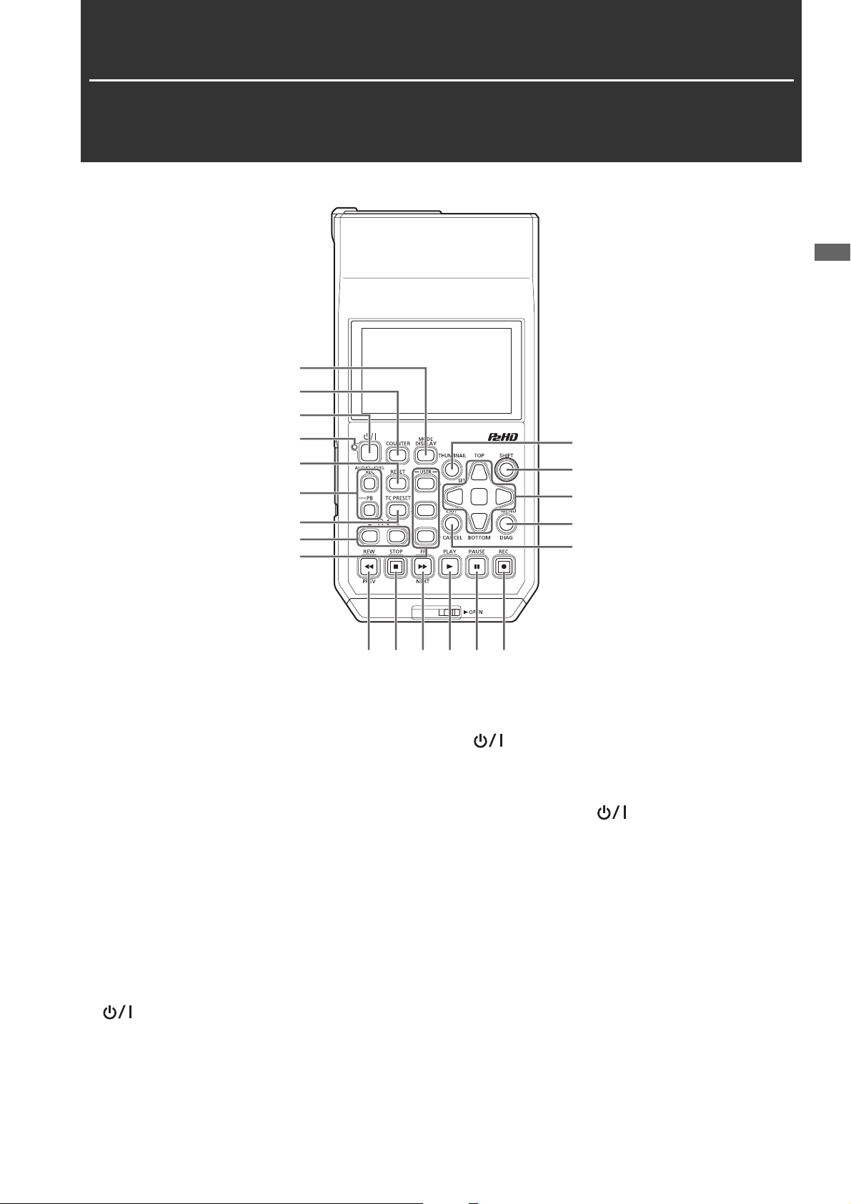
Controls
1
2
3
4
5
6
10
11
1
Control Reference Guide
7
8
9
13
14
15 16 17 18 19 20
About button labels: Orange labels indicate alternate functions enabled by simultaneously pressing the [SHIFT] button.
<Example> Press the [SHIFT] and [DISPLAY/MODE] buttons simultaneously to execute the [MODE] button function.
1. DISPLAY, MODE button
[DISPLAY] button:
This button toggles display of the OSD on and off.
(➝ “Screen Display” page 78)
[MODE] button:
This button switches between USB device mode (USB DEVICE) and PLAYLIST editing mode.
(➝ “USB Device Mode” page 75, “P2 Playlist Editing
Mode” page 76)
2. COUNTER button
This button switches the counter display in the following
order.
TC➝UB➝CTL➝TC
(➝ “Time Code, User Bits, and CTL” page 81)
3. (Power) button
This button turns the power on or off.
(➝ “How to Turn On/Off the Power” page 24)
4. (Power) lamp
This button displays the operating status of the unit.
(➝ “How to Turn On/Off the Power” page 24)
When an error is detected after the power is turned on or
during operation, the (POWER) lamp and a beep
sound notify you that an error has occurred. (➝ “Warning
Details” page 111)
5. RESET button
When the counter display on the display panel is CTL,
press this button to reset the counter display to
“0:00:00:00”.
(➝ “Time Code, User Bits, and CTL” page 81)
6. AUDIO LEVEL buttons
[AUDIO LEVEL-REC] button:
This button displays the recording audio level adjustment
screen.
(➝ “Recording Clips” page 31)
[AUDIO LEVEL-PB] button:
This button displays the playback audio level adjustment
screen.
(➝ “Playing Back Clips” page 34)
Control Reference Guide: Controls
15
Page 16

7. TC PRESET button
This button sets the TC or UB value.
(➝ “Time Code, User Bits, and CTL” page 81)
8. (Monitor volume adjustment) buttons
Monitor audio volume adjustment:
Press either the + or -, button to display the loudspeaker/headphone audio volume level, and hold the button to adjust. Wait a short time or press [SET] or [EXIT] to
return the display to normal.
9. USER 1-3, 4-6 buttons
Users can assign any functions to these buttons.
(➝ “USER BUTTON” page 102)
10.THUMBNAIL button
This button displays or hides the thumbnail screen.
(➝ “Displaying the Thumbnail Screen” page 37)
11.SHIFT button
Hold this button while pressing another button to perform
the assigned function of that button.
12.Cursor control buttons
Up/down/left/right cursor buttons:
• These buttons control the cursor movement for thumbnails, menus, etc.
• During playback, press the Left/Right cursor buttons to
activate SHTL mode to change playback speed.
(➝ “Variable speed playback” page 34)
• Press the [SET] button to pause variable speed playback.
• Press the up or down cursor button during the display of
playback still images to step one frame forward or back.
(➝ “Frame-by-frame playback” page 35)
• Use the left or right cursor button to switch the audio
channel for recording and playback audio level adjustment.
(➝ “Recording Clips” page 31)
[TOP]/[BOTTOM] buttons:
These buttons move the cursor to the first (TOP) or last
(BOTTOM) thumbnail.
[SET] button:
This button allows you to perform operations such as selecting thumbnails and menu items.
13.MENU, DIAG button
[MENU] button:
This button displays the menu.
[DIAG] button:
When the menu is not displayed, press this button to display the DIAG screen for viewing various conditions.
(➝ “Deck Information (DIAG) Display” page 80)
15.REW, PREV button
[REW] button:
This button fast rewinds playback.
The speed can be selected in the “FF.REW MAX” (➝ page
91) menu item.
[PREV] button:
This button cues the current or previous clip or the clip and
text memo location during playback.
16.STOP button
This button stops playback or recording.
17.FF, NEXT button
[FF] button:
This button fast forwards playback.
The speed can be selected in the “FF.REW MAX” (➝ page
91) menu item.
[NEXT] button:
This button cues the next clip or the clip and text memo location during playback.
18.PLAY button
This button starts playback.
(➝ “Playing Back Clips” page 34)
19.PAUSE button
Press this button during playback to pause (STILL) playback to display a still image.
Press the button while playback is paused to resume playback.
Press the button during recording to switch to the recording standby (PAUSE) state.
Press the button in the recording standby state to resume
recording.
20.REC button
This button allows you to check EE video and audio during
playback image output. EE will continue while the button is
being pressed.
EE mode monitoring is only available when the playback
video format matches the setting in the “LINE&FREQ” (➝
page 106) menu item. It will not function if recordable media does not exist.
Press this button and the [PLAY] button simultaneously to start recording.
Press this button and the [PAUSE] button simultaneously to switch to the recording standby state. Remote recording from a camera can be enabled from the menu.
Set remote recording in the “AUTO REC” (➝ page 90)
menu item.
14.EXIT, CANCEL button
[EXIT] button:
This button closes the menu or returns from the storage explorer to normal display.
[CANCEL] button:
This button cancels a selection, stops copying, etc.
Control Reference Guide: Controls
16
Page 17

Slots and I/O Controls
3
4
2
1
5
6
1. microP2 memory card slots
(➝ “P2 Cards” page 26)
2. microP2 memory card access lamps
(➝ “P2 Card Access Lamp and P2 Card Status” page 26)
3. EJECT button
(➝ “P2 Cards” page 26)
4. P2 memory card slot
(➝ “P2 Cards” page 26)
5. P2 memory card access lamp
(➝ “P2 Card Access Lamp and P2 Card Status” page 26)
6. Speaker
This speaker outputs the monitor audio.
Output from the speaker is disabled when headphones
are connected.
Control Reference Guide
Control Reference Guide: Slots and I/O Controls
17
Page 18

3 2
1
4 5 76
1. SD/SDHC/SDXC memory card slot and access lamp
Insert an SD/SDHC/SDXC memory card.
Insert the cut-corner-edge first with the label-side up, until
the card latches into place.
When removing a card, check that the access lamp is not
lit green, then release the latch by gently pushing the card
in again.
Note:
Use SD/SDHC/SDXC memory cards for reading the CPS password, reading and writing menu settings, reading and writing
metadata, and proxy recording.
(➝ “Using SD/SDHC/SDXC Memory Cards” page 29)
2. HDMI OUT connector
Connect a monitor or TV using an HDMI cable.
Note:
• This unit does not support Viera Link. Be aware that connecting a Viera Link compatible device using an HDMI cable
may cause Viera Link to malfunction on the other device.
• Use a double-shielded cable to connect to this port.
• When “VIDEO” - “INPUT SEL” is set to “HDMI”, video, audio,
and other signals from the HDMI output connector will not be
output. In addition, the thumbnail screen will not be output.
3. HDMI IN connector
Use an HDMI cable to connect a camera recorder, etc.
here.
Note:
• This unit does not support Viera Link. Be aware that connecting a Viera Link compatible device using an HDMI cable
may cause Viera Link to malfunction on the other device.
• Use a double-shielded cable to connect to this port.
• When HDCP signals are detected, external output is
stopped and recording will not be possible. In addition, the
thumbnail screen will not be output.
• This unit does not support 60 Hz JUST frequency signals.
For the input signals, use 59.94 Hz or 50 Hz signals. Even
when using 59.94 Hz or 50 Hz signals, if there is a discrepancy in the frequency, reception will not be possible (in the
case of some computers, for example).
• When an input signal cannot be received, the “INVALID
INPUT FORMAT
will be black and muted.
” warning will be displayed and the video
8
4. USB 3.0 HOST port (USB 3.0 Type A)
(➝ “Connecting an External Device via the USB HOST
Port” page 53)
Note:
• Use a double-shielded cable to connect to this port.
• Use a USB 3.0 compliant cable to connect USB 3.0 compatible storage devices.
• When using this unit with the battery, externally supply power to any storage device connected to the [USB3.0 HOST]
port.
5. USB 2.0 device port
(➝ “USB Device Mode” page 75)
Note:
Use a double-shielded cable to connect to this port.
6. LAN port
This port enables a 100BASE-TX/10BASE-T network connection.
(➝ “Using the Unit Connected to a Network” page 61)
Note:
• Use a shielded cable to connect to this port.
• The orange lamp lights when a LAN link is established. The
green lamp flashes while data is being transferred.
7. AUDIO OUT connector
Outputs the audio signals (CH1 to CH4) selected in the
“MONITOR CH” (➝ page 97) menu item.
8. PHONES (Headphone) jack
Headphone jack:
This jack is for connecting stereo headphones to listen to
the sound being recorded or played back with the headphones.
Control Reference Guide: Slots and I/O Controls
18
Page 19

I/O Connectors and Power Components
3
2
4
5
1. ANALOG AUDIO IN jacks
These jacks are for inputting analog audio.
2. HD/SD-SDI IN/OUT jacks
These jacks are for inputting and outputting serial digital
component audio/video signals.
The output jack for superimposition can be changed in the
“OSD OUTPUT” (➝ page 100) menu setting, and the output jack for thumbnail screen superimposition can be
changed in the “GUI OUTPUT” menu setting (➝ page
100).
1
Control Reference Guide
Note:
Use 5C-FB or equivalent double-shielded cables to connect
to these jacks.
3. TIME CODE IN Jacks
This jack is for recording an external time code onto a P2
card.
4. Battery lock release button
(➝ “Using the Battery” page 22)
5. Battery attachment point
(➝ “Using the Battery” page 22)
Control Reference Guide: I/O Connectors and Power Components
19
Page 20
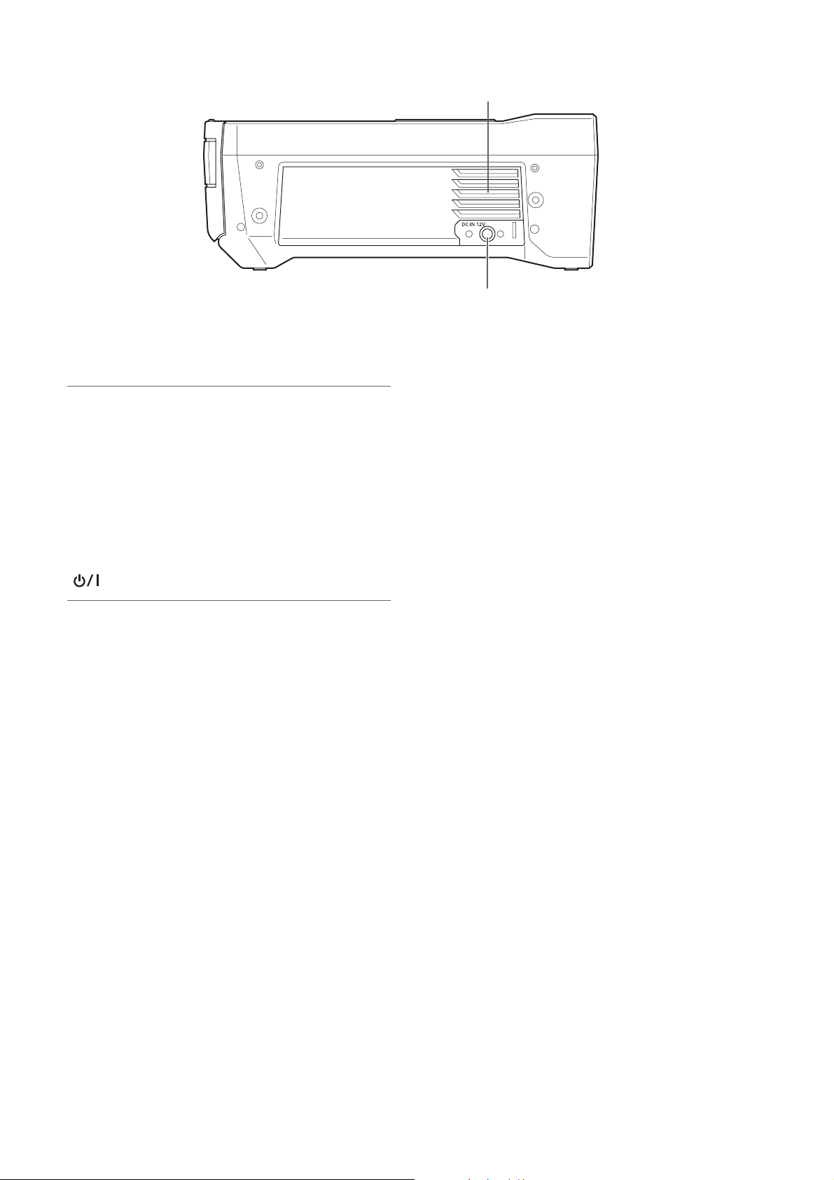
1. Fan
This fan is for cooling the unit. Install the unit where the
ventilation holes will not be blocked.
Note:
If the fan is stopped while the power is on, the “FAN
STOPPED” (➝ page 113) warning is displayed. Stop operation and turn off the unit immediately, and contact your dealer.
2. DC IN connector
Connect a 12 V DC power supply.
When the voltage drops to approximately 10.0 V, the unit
is shutdown automatically.
Afterwards, the power is not restored automatically even if
the power supply voltage recovers. Press and hold the
[ ] button for at least 1 second to turn the power on.
1
2
Note:
When using an external DC power supply, be sure to check
the external DC power supply ratings and use one that is suitable for the unit.
Check the pin assignment of the DC output connector of the
external DC power supply and the DC IN connector on the
unit, and connect the connectors with the correct polarity. Incorrect connection of the +12 V power supply to the GND
connector may cause a fire or injury.
Control Reference Guide: I/O Connectors and Power Components
20
Page 21
Preparation
Power Supply
You can use a battery or AC adaptor to supply power to the unit.
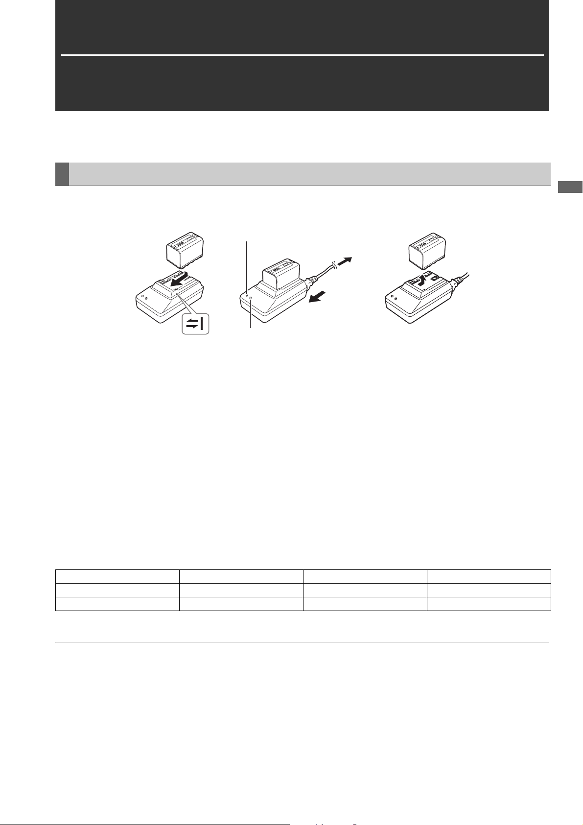
Charging the Battery
The battery is not charged at the time of purchase. Before using the battery, fully charge it with the battery charger.
We recommend keeping one spare battery on hand.
[POWER] lamp
To power outlet
(2)
(1)
[CHARGE] lamp
Figure 1 Figure 2 Figure 3
1 Place the battery so that it is level on the battery charger, and slide it in the direction indicated by the marks on
the charger (Figure 1).
Push the battery in firmly.
2 Connect the AC power cable (Figure 2).
Connect the AC power cable in the order indicated in the figure.
•[POWER] lamp
- Lights when the AC power cable is connected.
• [CHARGE] lamp
- On: Charging.
- Off: Charging is complete.
- Flashing: Reinsert the battery.
Preparation
3 Slide the battery to remove it (Figure 3).
Charging time and playback time estimates
Battery model Voltage/capacity Charging time Continuous playback time
VW-VBD58 (supplied accessory) 7.2 V/5800 mAh Approx. 380 minutes Approx. 170 minutes
VW-VBD55 (optional accessory) 7.2 V/5400 mAh Approx. 330 minutes Approx. 160 minutes
• The times are when the ambient temperature is 20 °C and the relative humidity is 60%. The charging time may be longer
under other temperature and humidity conditions.
Note:
• The above table shows estimates for playback in AVC-Intra 100 mode.
• Operation is not guaranteed for battery pack VW-VBD33 (1500 mAh).
• The battery and unit become hot during usage and charging.
• Store the battery in a discharged state.
• When the battery is stored for an extended period of time, we recommend that once a year you charge the battery and then use up
the charge with the unit before storing the battery again.
• When the battery temperature becomes excessively high or low, the [CHARGE] lamp flashes several times and then charging starts
automatically.
• When the battery is left discharged without being used for a long period of time, the [CHARGE] lamp flashes several times and then
charging starts automatically.
Preparation: Power Supply
21
Page 22
• If the [CHARGE] lamp continues flashing even though the battery is at a normal temperature, the battery or battery charger may have
malfunctioned. Contact your dealer.
• When the battery is hot, the charging time will be longer than usual.
• If the battery charger is used near a radio, the sound of the radio may become distorted. Place the battery charger at least 1 meter
away from a radio.
• The battery charger may emit noise during use but please note that this is not a sign of a malfunction.
• Level indicator function
A battery LED indicator allows you to check an estimate of the battery level.
The level indicator may differ when the battery is being used in the unit and when it is separate from the unit.
• The supplied battery is designed specifically for the unit.
Do not use it with other equipment.
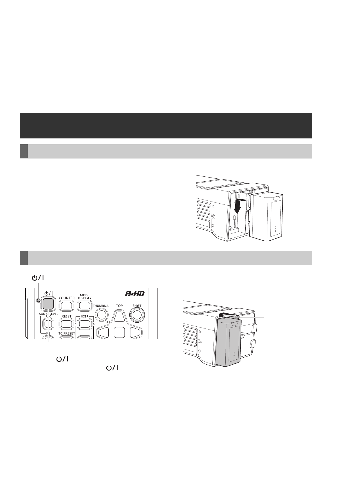
Using the Battery
Installation
1 Slide the battery until it clicks into place.
Removal
lamp
1
1 Press the [ ] button for two seconds to turn the
power off, and confirm that the lamp has turned
off.
2 Remove the battery while pressing the battery latch
release button.
Support the battery with a hand to prevent it from falling.
Note:
If the power is on, be sure to turn it off before removing the
battery.
Battery latch
release button
Preparation: Using the Battery
22
Page 23
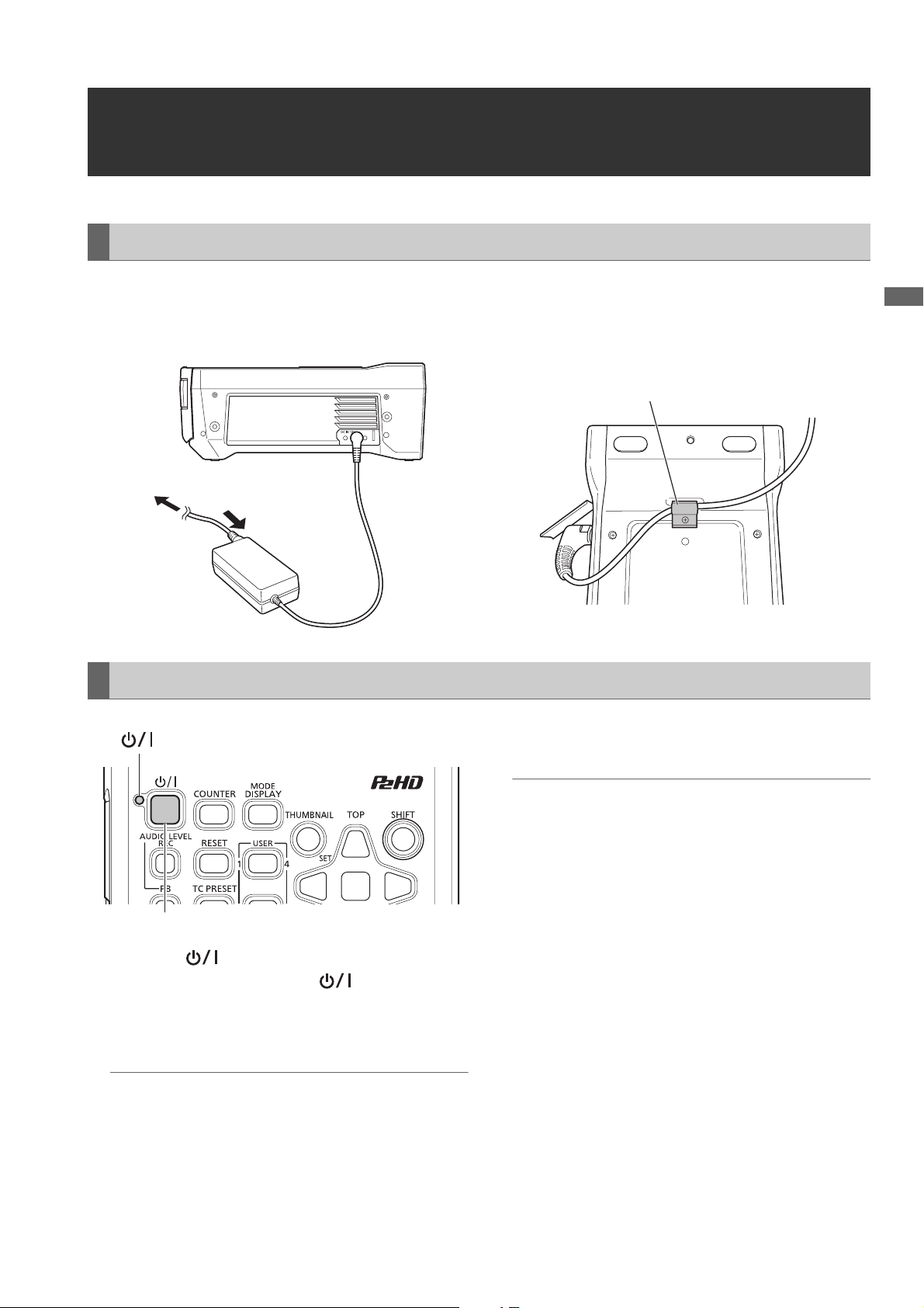
Installation
Using the AC Adaptor
1 Connect the AC power cable.
Connect the AC power cable in the order indicated in the
figure.
To power outlet
(2)
Removal
lamp
(1)
2 Insert the DC power cable plug into the DC IN con-
nector.
3 Clamp the DC cord.
Clamp
3 Disconnect the AC power cable (for the AC adaptor)
from the power outlet.
Preparation
1
1 Press the [ ] button for two seconds to turn the
power off, and confirm that the lamp has turned
off.
2 Remove the DC power cable plug.
Note:
If the power is on, be sure to turn it off before removing the DC
power cable plug.
Note:
• The AC adaptor is designed to operate with all power supply
voltages (100 V to 240 V) and frequencies (50 Hz/60 Hz)
around the world. However, the shape of the power outlet
differs depending on the country. Use a plug that is designed for the country of use. If necessary, contact your supplier to obtain the appropriate plug adaptor.
• When you will not use the unit, disconnect the AC power cable (for the AC adaptor) from the power outlet.
Preparation: Using the AC Adaptor
23
Page 24
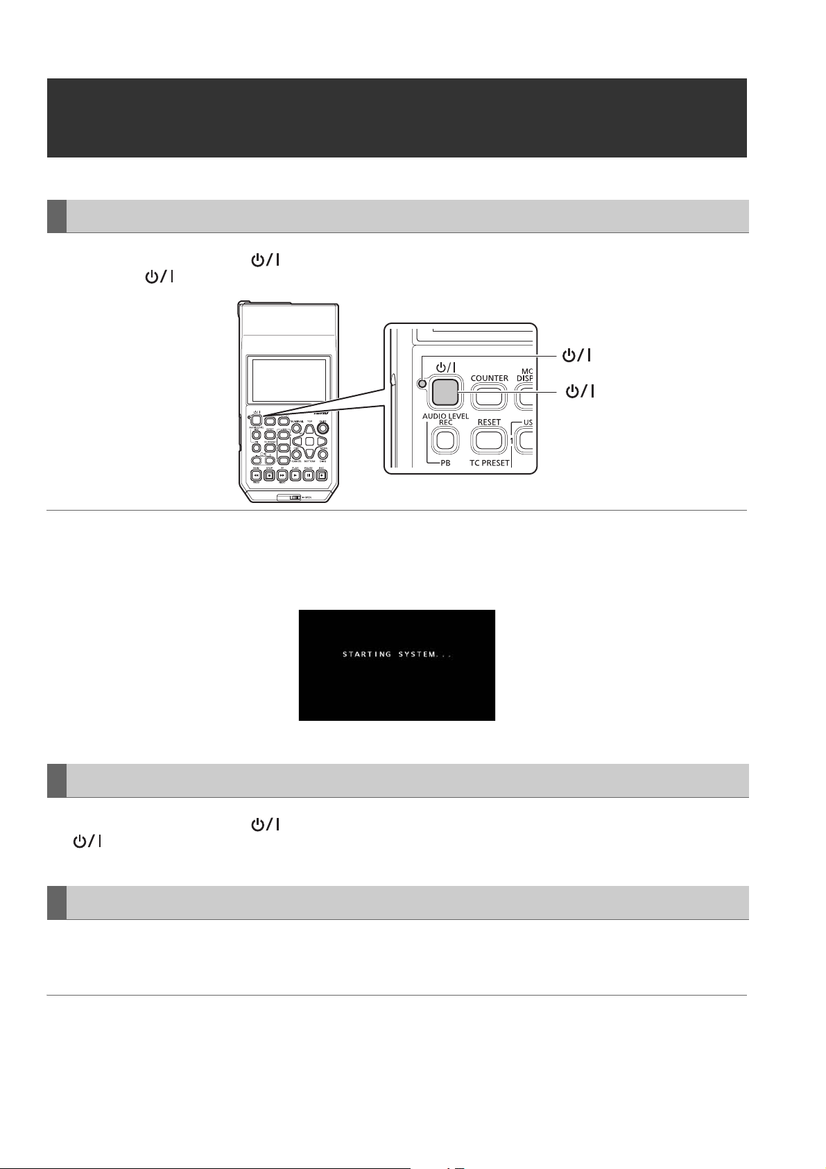
How to Turn On/Off the Power
Turning On the Power
From the power-off state, press the [ ] button for one second to turn the power on.
After startup, the lamp lights green.
lamp
[ ] button
Note:
The following messages appear during startup.
• “STARTING SYSTEM...”: Flashes during startup.
• “AUTO POWER OFF = ¾ min”: The time set in the “AUTO POWER OFF” (➝ page 95) menu item is displayed instead of “½.” When
the menu item setting is set to OFF, this message is not displayed.
Turning Off the Power
From the power-on state, press the [ ] button for at least two seconds to turn off the power.
The lamp flashes during the power-off process, and then turns off.
Auto Power Off during Operation
The unit has a function to automatically turn the power off after a short period of time if no operation such as recording, playback,
copying, or formatting is performed during that time. To resume operation after the power turns off automatically, turn the power
on again.
Note:
The time until the power turns off can be set in the “AUTO POWER OFF” (➝ page 95) menu item.
Preparation: How to Turn On/Off the Power
24
Page 25

Setting the Year, Month, Day, and Time
Set the clock before using the unit the first time.
1 Press the [ ] button on the unit for one second to
turn the power on.
2 Press the [MENU] button to display the menu.
(➝ “Menu Operations” page 83)
3 Use the cursor buttons to select the “I/F SETUP” -
“CLOCK” menu item and then press the [SET] but-
ton.
The clock setting screen appears. The default values are
the current time settings.
4 Use the left and right cursor buttons to select the dig-
its to be set.
• Display is in the order of hour/minute/month/day/year/
time zone.
• For the time zone, set the difference in hours from Greenwich Mean Time.
• The time is displayed in the 24-hour format.
5 Use the up and down cursor buttons to set the year,
month, day, time, and time zone.
6 After configuring the settings, press the [SET] button.
Pressing the [SET] button sets the clock to the changed
time.
Note:
• The clock is affected by deviation so check that the time is
correct before use.
• When an accurate time is required, check and reset the time
before use.
Time zone
Time
difference
00:00 Greenwich +01:00 Central Europe
-00:30 +01:30
-01:00 Azores Islands +02:00 Eastern Europe
-01:30 +02:30
-02:00 Mid-Atlantic +03:00 Moscow
-02:30 +03:30 Tehran
-03:00 Buenos Aires +04:00 Abu Dhabi
-03:30 Newfoundland
-04:00 Halifax +05:00 Islamabad
-04:30 +05:30 Bombay
-05:00 New York +06:00 Dacca
-05:30 +06:30 Yangon
-06:00 Chicago +07:00 Bangkok
-06:30 +07:30
-07:00 Denver +08:00 Beijing
-07:30 +08:30
-08:00 Los Angeles +09:00 Tokyo
-08:30 +09:30 Darwin
-09:00 Alaska +10:00 Guam
-09:30 Marquesas
-10:00 Hawaii +11:00 Solomon Islands
-10:30 +11:30 Norfolk Island
-11:00 Midway Island +12:00 New Zealand
-11:30 +12:45 Chatham Islands
-12:00 Kwajalein +13:00
+00:30
About the battery of the internal clock
If the battery of the internal clock is empty because, for example, power has not been supplied for a long period of time, the
“BACKUP BATT EMPTY” warning will be displayed. If that
happens, connect the AC adaptor and then leave the unit for
approximately 4 hours to charge the battery. If the “BACKUP
BATT EMPTY” warning is displayed after charging, the internal battery needs to be replaced. Ask your dealer to replace
the battery.
Area
Island
Islands
Time
difference
+04:30 Kabul
+10:30 Lord Howe Island
Area
Preparation
Preparation: Setting the Year, Month, Day, and Time
25
Page 26

P2 Cards
P2 Card Access Lamp and P2 Card Status
P2 Card Access Lamp P2 Card Status
Lights green Recording possible Both writing and reading are possible.
Lights orange Recording target Writing and reading are enabled and currently recording target.
Flashing orange Card being accessed Writing or reading is in progress.
Fast flashing orange Card being recognized The P2 card is being recognized.
Slow flashing green Card full There is no available space on the P2 card. Only reading is possible.
Write protected The write-protect switch on the P2 card is set to Protect. Only reading is pos-
sible.
Off
Card not supported for recording
Slot not target for recording
Card not supported The card cannot be used with the unit. Replace the card.
Format invalid The P2 card is not formatted properly. Reformat it.
No card A P2 card is not inserted. Waiting for the card to be recognized.
Card cannot be authenticated
No USB access The P2 card is not accessible using USB device mode.
Recording is not possible with the currently set recording format because an
SD memory card or other unsupported card is inserted. Only reading is possible. To record, change the recording format or use a P2 card.
A card has been inserted in a different slot from that of "REC MEDIA"
(microP2/P2) (➝ page 91) of the "REC/PB SETUP" menu item.
A microP2 memory card for which authentication is not possible. Refer to
“Manual and Automatic CPS Authentication” (➝ page 51) and then perform
authentication.
Note:
“FORMAT ERROR!” or “NOT SUPPORTED!” may appear if a microP2 memory card is inserted slowly. Should this happen, reinsert it.
P2 Card Recording Times
P2 cards supported by the unit
The unit supports separately sold P2 memory cards and microP2 memory cards of 4 GB to 64 GB. (As of December 2014)
Note:
• When AVC-Intra100 of 1080/59.94p and 1080/50p is selected, recording to the following P2 cards is not possible.
- H, R, A, and E series P2 memory cards.
- Card attached to microP2 card adaptor (AJ-P2AD1G)
• AJ-P2C002SG (2 GB) cards cannot be used.
• The unit may need to be updated depending on the type of P2 card.
• For the latest information not available in the Operating Instructions, visit the website. (➝ “Website URL” page 9)
Preparation: P2 Cards
26
Page 27

P2 card recording times
(Example of using one 64 GB card)
“LINE&FREQ” setting (recording format) “REC FORMAT” setting (codec) Recording duration
1080-59.94P, 1080-50P AVC-I100 Approx. 32 minutes
AVC-G25 Approx. 110 minutes
1080-59.94i, 1080-50i AVC-I100 Approx. 64 minutes
AVC-G25 Approx. 220 minutes
720-59.94P, 720-50P AVC-I100 Approx. 64 minutes
AVC-G25 Approx. 220 minutes
480-59.94i, 576-50i DVCPRO50 Approx. 128 minutes
DVCPRO Approx. 256 minutes
Note:
• The recording times for 32 GB, 16 GB, and 8 GB P2 cards are 1/2, 1/4, and 1/8th of those shown above, respectively.
• The displayed sizes include the management area, for example, so the amount of space available for recording will be less than the
above.
Dividing of clips recorded to P2 cards
When an 8 GB or larger P2 card is used with the unit, continuous recordings longer than the durations shown in the table below
result in automatic division of the recording into multiple clips. However, on a P2 device, such recordings are handled as a
single clip for thumbnail operations (display, delete, repair, etc.). Such recordings may be displayed as separate clips in nonlinear editing software or on a computer or other device.
When recording to a microP2 memory card exceeding 32 GB using the AVC-LongG codec, you can enable continuous recording as the same clip in the “FILE SPLIT” (➝ page 91) menu item.
Recording in which the same clip exceeds 4 GB is possible, but copying to storage using the usb-host mode of the unit will not
be possible.
Furthermore, you will not be able to copy the clip if the maximum size of one file is restricted to, for example, 4 GB by the format
(NTFS, FAT32, etc.) of the storage of the computer or other device, so configure the settings to match your environment.
Recording formats (excluding native recording) Continuous recording duration
AVC-I100 (1080p) Approx. 3 minutes
AVC-I100 (1080i), DVCPRO HD Approx. 5 minutes
AVC-G50, AVC-I50, DVCPRO50 Approx. 10 minutes
AVC-G25, DVCPRO, DV Approx. 20 minutes
Preparation
Content Protection System (CPS)
microP2 memory cards support the content protection system (CPS), which is a security function that prevents data leakage to
third parties by recording in an encrypted format.
To use the CPS function, you need to set a CPS password and enable the microP2 memory card authentication function (➝
“Manual and Automatic CPS Authentication” page 51) and encrypted format function (➝ “Formatting P2 Cards and SD Memory
Cards” page 50) on the unit. microP2 memory cards in an encrypted format are authenticated automatically to enable use as
microP2 memory cards for recording and playback only on devices for which the same CPS password is set. For details on CPS
passwords, refer to “Manual and Automatic CPS Authentication” (➝ page 51).
Note:
• Up to 16 characters can be set for the password.
• An encrypted microP2 memory card cannot be recognized in an SD slot of a computer.
• If an authentication error occurs, perform authentication again with the correct password, format the card to enable use as storage
media, or eject it from the device. Do not perform any operation other than manual authentication or formatting while a card for which
an authentication error has occurred is inserted.
• To access an encrypted microP2 memory card from a computer when in USB device mode, perform authentication for the microP2
memory card with P2 Viewer Plus.
Preparation: P2 Cards
27
Page 28

Handling of Recording Data
P2 memory cards and microP2 memory cards are semiconductor memory cards designed for the P2 series, Panasonic’s line
of professional video and broadcast equipment.
Recording data in the P2 format is ideally suited for com-
puter processing because it is a file format. The file structure includes not only video and audio data recorded in
the unique MXF file format but also various important information, and has the folder configuration shown on the
right.
If any of this data is changed or deleted, a problem may occur, such as the data being unable to be recognized as P2
data or the card no longer being able to be used in a P2 device.
A P2 card that has been formatted in other than a microP2
memory card compatible device will not contain the AVCLIP folder. For a P2 card without an AVCLIP folder, the
folder will be created automatically when recording is performed on a microP2 memory card compatible device.
To prevent data loss when transferring the data on a P2
card to a computer or other device or when writing the data stored on a computer back to a P2 card, be sure to use the dedicated P2 Viewer Plus software, which can be downloaded from the Panasonic website.
For the URL, refer to (➝ “Website URL” page 9)
When transferring data to a computer using a general IT tool such as Microsoft Windows Explorer or Apple Finder, observe
the following. Be sure to use P2 Viewer Plus to write the data back to a P2 card.
• Process the CONTENTS folder and the LASTCLIP.TXT file together.
Do not modify any data under the CONTENTS folder.
When copying the data, be sure to copy both the CONTENTS folder and the LASTCLIP.TXT file together.
• When transferring the data from multiple P2 cards to a computer, create a separate folder for each P2 card to prevent the
overwriting of clips with identical names.
• Do not delete data on a P2 card.
• Be sure to use a P2 device or P2 Viewer Plus to format P2 cards.
Drive:\
CONTENTS
AVCLIP
AUDIO
CLIP
ICON
PROXY
VIDEO
VOICE
LASTCLIP.TXT*
All of the folders are required.
1
*
This file contains the data for the last clip
recorded on the P2 device.
1
Preparation: Handling of Recording Data
28
Page 29

Using SD/SDHC/SDXC Memory Cards
Use only SD, SDHC, and SDXC*1 memory cards that comply with the SD, SDHC, and SDXC*3 standards in the unit. Memory
cards other than SD, SDHC, and SDXC cards (for example, MultiMediaCard
1
*
The SDHC memory card is a new card standard (version 2.0), established by the SD Card Association in 2006, for memory
cards with capacities exceeding 2 GB.
2
*
MultiMediaCard (MMC) is a registered trademark of Infineon Technologies AG.
3
*
The SDXC memory card is a new standard (version 3.0), established by the SD Card Association in 2009, for memory cards
with capacities exceeding 32 GB.
• When using a miniSD, miniSDHC, microSD, microSDHC, or microSDXC card in the unit, be sure to use it with the correct dedicated adaptor attached. (Note that the unit will not operate normally when only an adaptor without a card is inserted.)
• Be sure to use the unit to format cards.
• The unit supports SD, SDHC, and SDXC memory card of the following sizes.
SD: 8 MB to 2 GB
SDHC: 4 GB to 32 GB
SDXC: Over 32 GB
Use of Panasonic SD, SDHC, and SDXC memory cards and miniSD, miniSDHC, microSD, microSDHC, and microSDXC cards
is recommended.
• The latest information on supported memory cards is available on our P2 Support website.
For the URL, refer to (➝ “Website URL” page 9)
2
*
) cannot be used.
Preparation
Preparation: Using SD/SDHC/SDXC Memory Cards
29
Page 30
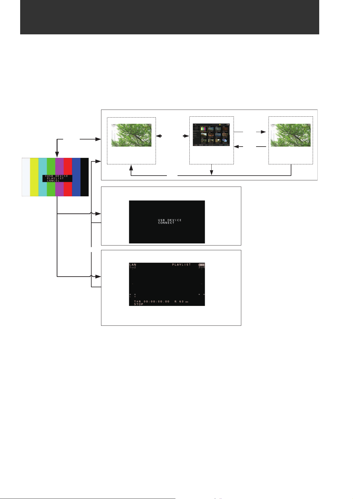
Available Modes
This unit comes with three modes: Main mode, USB device mode, and playlist editing mode.
You can select or change the mode by selecting one of the menu items displayed when you press the [MODE] button. Main
mode has a thumbnail screen for displaying and managing clip thumbnails and playing clips and a recording/playback screen
for recording and playback.
The figure below shows an overview of each mode.
• Recording/playback screen: Displays video, time code, and other information and enables recording and playback.
• Thumbnail screen: Displays clip thumbnails, various properties, and other information and enables the management and
playback of clips.
Main mode: Recording and playback
PLAY
STILL
STOP
Playback screen
Mode menu
䇭MODE䇭
SET
THUMBNAIL
Recording/
playback screen
REC
USB device mode: Connecting to computer or other
devices
Thumbnail
screen
MODE
Playlist editing mode: Editing playlists via a network using
a web browser.
You can only switch to this mode when you have configured the
network connection settings. (➝ “Using the Unit Connected to a
Network” page 61)
Available Modes:
30
Page 31

Main Mode
Recording/Playback Screen
Use the recording/playback screen for the following.
• Recording to P2 cards
• Playing back all cards in the order they were recorded
Recording Clips
Record audio and video as clips.
Recording clips
Before you start recording, set the recording frequency, format, slot for recording, input signal, and other settings in the
menu.
(➝ Setup Menu “SYSTEM MODE” page 106, “REC/PB” page
90)
Note:
If analog is selected for audio input, a 4-channel audio file will be
created but no sound will be recorded on any channel other than
channels 1 and 2.
Adjusting the recording audio levels
Follow the procedure below to change the volume level for recording.
1. Press the [AUDIO LEVEL-REC] button.
The recording volume appears.
2. Operate the up or down cursor button.
3. Use the left or right cursor button to select an audio
channel.
The selected channel number flashes. Each of the channels can be adjusted.
4. After adjustment is finished, press the [AUDIO
LEVEL - REC] button, [SET] button or [EXIT] button.
The setting values are saved and the displayed information disappears.
Note:
• The setting values do not change when you turn off the power.
• If you press the [RESET] button during the changing of the
audio levels, the level of the selected channel is restored to
the default value.
Changing the recording slot
With the microP2 card slots, the recording target slot can be
changed during recording or when recording is stopped.
Main Mode
23
1 Insert a P2 card.
2 Press the [PLAY] button while holding down the
[REC] button.
Recording begins on the P2 card in the slot with the access lamp is lit orange.
Note:
Setting the “DUAL CODEC SETUP” - “CODEC USAGE” (➝
page 92) menu item to “PROXY REC(P2)” or “PROXY
REC(P2&SD)” and then recording will start proxy recording simultaneously with the recording of the main material. (➝ “Dual codec (proxy) recording” page 33)
3 Press the [STOP] button to stop recording.
Note:
Recording to a mixture of the P2 memory card slots (3) and
microP2 memory cards slots (1 and 2) is not possible. Select
the recording target slots in the “REC/PB SETUP” - “REC
MEDIA” (➝ page 91) menu item.
1
2
1. Assign the SLOT SEL function to a [USER] button in
the “USER BUTTON” (➝ page 102) menu item.
2. Press the [USER] button during recording or when
recording is stopped.
The recording slot changes with each press of the button.
Note:
• When you do not perform SLOT SELECT right after switching
the recording target P2 card, “SLOT SEL INVALID” will appear on the third line of the OSD if the “OSD TC SELECT” (➝
page 100) menu item is set to “T&S&M.”
• The slots can be switched with the SLOT SEL function only
when “microP2” is selected in the “REC/PB SETUP” - “REC
MEDIA” (➝ page 91) menu item.
Main Mode: Recording/Playback Screen
31
Page 32

Various types of recording
Hot swap recording
When P2 cards are inserted in both of the microP2 memory
card slots, continuous recording spanning both cards is possible. You can also record continuously on three or more
cards (hot swap recording) by replacing one card while recording on the other.
Note:
• P2 card recognition may be delayed and prevent hot swap recording depending on the timing at which a P2 card is inserted
in the empty slot (immediately prior to or after recording continues onto the other card).
It is recommended to insert a P2 card when there is still at least
1 minute of time left on the card currently being used for recording.
• The unit does not support hot-swapping during playback.
LOOP REC
LOOP REC is a function for recording continuously while successively switching the card target for recording when two P2
cards are inserted in the microP2 memory card slots. Recording can be performed continuously by returning to the first
card when the available space on the P2 cards has been used
up and then overwriting the old recording with the new recording.
To use the LOOP REC function, select “LOOP” in the “RECORDING” (➝ page 90) menu item.
Note:
• The LOOP REC function can only be used with microP2 memory
cards. It cannot be used with P2 memory cards.
• Use P2 cards with at least one minute of free space for loop recording.
• During loop recording, all of the P2 card access lamps for the
P2 cards used for recording are lit orange. Note that removing
any of the P2 cards will stop loop recording.
When “LOOP” is selected in the “RECORDING” menu item
• "LOOP" is displayed on the second line of the OSD. However,
even when “LOOP” is selected in “RECORDING,” the loop recording will not work if only one card is inserted or the remaining
recording time on a card is less than 1 minute. Should this happen, “LOOP” will flash on the OSD.
• The remaining space of P2 cards is indicated as the standard
guaranteed recording time according to the recording format.
When loop recording is stopped right after deleting old data, the
actual remaining time may be shorter than indicated.
• Proxy recording cannot be performed.
During loop recording
• Shot marks cannot be added or deleted. Also, text memos cannot be added.
Canceling loop recording mode
• Select “NORMAL” in the “RECORDING” menu item.
AUTO REC
When a camera compatible with the function is connected via
HD SDI or HDMI, starting and stopping recording on the unit
can be automatically controlled using the REC START / STOP
function on the camera.
1. Match the “AUTO REC” (➝ page 90) menu item to
the camera to be used.
2. Press the [REC] button and [PAUSE] button
on the unit simultaneously to switch to REC PAUSE
mode.
Now you can start and stop recording on the unit using the
REC START / STOP function on the camera.
Note:
There may be a delay in the recording start and stop operations
on the unit in relation to those of the camera, and complete accuracy is not guaranteed.
SIMUL REC
This is a function for recording the same images to two P2
cards when two P2 cards are inserted in the microP2 memory
card slots.
To use the SIMUL REC function, select “ON” in the “SIMUL
REC” (➝ page 90) menu item.
Note:
• The remaining amount of time (of the memory card with less remaining space) for SIMUL REC will be displayed for the remaining space indication of the media.
• SIMUL REC will stop if either of the P2 cards in the respective
slots runs out of space.
• SIMUL REC will not be possible if “1080-59.94P” or “1080-50P”
is selected in the “LINE&FREQ” (➝ page 106) menu setting.
• If a recording error occurs and causes recording to stop on one
of the P2 cards during SIMUL REC, recording will continue on
the other P2 card. However, recording will end if a card is removed while it is being accessed.
• Make sure both P2 cards are recognized before starting recording. If you start recording before both P2 cards are recognized,
normal recording will be performed on the one card that was
recognized. The card status is checked when recording is complete. If two cards are recognized at that time, SIMUL REC will
be performed.
When “ON” is selected in the “SIMUL REC” menu item
• “SIMUL” is displayed on the second line of the OSD. Even if
“SIMUL REC” is set to “ON”, however, SIMUL REC will not function if one of the cards is not inserted. Should this happen,
“SIMUL” will flash on the OSD.
• If you press the record button while “SIMUL” is flashing, normal
recording will be performed on the card with remaining space.
Canceling SIMUL REC mode
• Select “OFF” in the “SIMUL REC” menu item.
Main Mode: Recording/Playback Screen
32
Page 33

Dual codec (proxy) recording
Simultaneously record video as well as time-code data and other real-time data in MPEG4 format or H.264 format to a P2 card
or SD memory card separately from the main video and audio material recorded with the unit.
(➝ “DUAL CODEC SETUP” page 92 menu item)
Recording modes and recording signals (video and audio)
Video Audio
Recording mode
LOW 2CH MOV
HQ 2CH MOV 640 x 360
SHQ 2CH MOV 960 x 540
AVC-G6 2CH MOV 1920 x 1080
Resolution Codec Bit rate Codec
1080i mode
480 x 270
1080 59.94/50p mode
320 x 180
H.264
Baseline Profile
H.264
High Profile
H.264
High Profile
H.264
High Profile
800 kbps AAC-LC 2 channels 64 kbps
1500 kbps AAC-LC 2 channels 64 kbps
3500 kbps Linear PCM 2 channels 768 kbps
6 Mbps AAC-LC 2 channels 64 kbps
Number of chan-
nels
Bit rate per channel
Main Mode
Recording proxy data
Set the “DUAL CODEC SETUP” - “CODEC USAGE” (➝ page
92) menu item to “PROXY REC(P2)” or “PROXY REC(P2&SD)”
and then press the [PLAY] button while holding down the
[REC] button to start proxy recording simultaneously with
the recording of the main material.
• You can check detailed information on the recorded proxy
data from the properties of the clip.
(➝ “Viewing the clip metadata information” page 46)
• Proxy data is recorded to a P2 card or SD memory card as
a video and audio file and a real-time data file.
Video and audio file: ½½½½½½½½.MOV
Real-time metadata file: ½½½½½½½½.BIN
The time code, user bits, and other information are recorded on a frame basis.
Note:
• Dual codec recording is not possible in the following modes.
-LOOP REC
-SIMUL REC
- 480-59.94i or 576-50i
• When "1080-59.94p" or "1080-50p" is set for the "LINE&FREQ"
(➝ page 106) menu setting, AVC-G6 2CH MOV cannot be recorded.
• “AVC-G6 2CH MOV” cannot be recorded when the “REC
FORMAT” menu item (➝ page 106) is set to “DVCPRO HD”,
“AVC-G12”, or “AVC-I50”.
• When recording proxy data to an SD memory card, use an SD
memory card of class 2 or above.
• The SD memory card access lamp lights green during the re-
cording of proxy data to the SD memory card.
• If short recordings are repeated, the available recording time
may decrease significantly compared to the available space.
• When the number of clips becomes 1,000 or more, proxy data
cannot be recorded to the SD memory card even if there is free
space remaining. Check the number of clips recorded to the SD
memory card in “NUMBER OF CLIP” of the “SD CARD PROPERTY” (➝ page 103) menu item.
• Shot marks and text memos cannot be added to clips in an SD
memory card.
• Even if you delete the clips recorded to the P2 card in the
thumbnail screen, the proxy data recorded to the SD memory
card will not be deleted.
Checking proxy data
• The indicator is displayed for a clip of material for which
proxy data recording was performed.
• Check the proxy data in P2 Viewer Plus. The data may not
be able to be checked depending on the version of P2
Viewer Plus. For information on P2 Viewer Plus, visit the
Panasonic website. (➝ “Website URL” page 9)
• Proxy data cannot be played with the unit.
Main Mode: Recording/Playback Screen
33
Page 34

Playing Back Clips
Variable speed playback
The playback speed can be varied to search for a scene.
Playback
Before you start playback, set the playback frequency, format, and other settings in the menu. (➝ Setup Menu “SYSTEM
MODE” page 106)
12
1 Press the [PLAY] button.
Playback begins. Clips play back in the order they were
recorded.
Note:
• Pressing the [REW] button instead of the [PLAY]
button rewinds playback, while pressing the [FF] button
fast forwards playback.
• When clips in different compression formats are played
back, the video and audio between clips may be distorted.
• When clips with the same video format but different audio bit
rates are played back continuously, the audio between clips
will be muted.
1 Press the left or right cursor button during playback
or STILL.
Playback changes to high-speed or slow and indicated as
SHTL +/– speed.
2 Press the left or right cursor button to change play-
back speed.
• The playback speed changes each time the buttons are
pressed. Maximum playback speed depends on the value
set by the REC/PB - REC/PB SETUP - SHUTTLE MAX menu
setting (➝ Setting Menu “REC/PB SETUP” - “SHUTTLE
MAX” page 91).
• Audio is not played back at speeds faster than 10 times normal speed.
• The right cursor button changes the speed in forward direction and the left cursor button changes the speed in backward direction.
• Press the [STILL/PAUSE] button or [SET] button to pause
playback. To return to normal playback, press the [PLAY]
button.
• The pulldown sequence may not be uniform for variable
speed playback of native recorded (including x1 speed)
video.
• Not all of the frames of a clip recorded in AVC-G format will
be played back during reverse playback and fast playback.
2 Press the [STOP] button.
Playback stops and the input video (EE) is displayed.
Adjusting the playback audio levels
Follow the procedure below to change the playback levels.
1. Press the [AUDIO LEVEL-PB] button.
The playback volume appears.
2. Press the up or down cursor button.
The levels of all channels can be adjusted.
3. Use the left or right cursor button to select an audio
channel.
The selected channel number flashes. Each of the channels can be adjusted.
4. After adjustment is finished, press the [AUDIO
LEVEL - PB] button or [EXIT] button.
The setting values are saved and the displayed information disappears.
Note:
• The setting values do not change when you turn off the power.
• If you press the [RESET] button during the changing of the
audio levels, the level of the selected channel is restored to
the default value.
Main Mode: Recording/Playback Screen
34
Page 35

Frame-by-frame playback
2
1
1 Press the [PAUSE] button to switch to still image
mode.
2 Press the up or down cursor button.
• The up cursor button performs frame-by-frame playback
in the forward direction and the down cursor button performs frame-by-frame playback in the backward direction.
• Holding down a cursor button performs continuous
frame-by-frame playback. To return to normal playback,
press the [PLAY] button.
Main Mode
One clip playback (1 CLIP PLAY)
1 Assign the “1 CLIP PLAY” function to a [USER] but-
ton in the “USER BUTTON” menu.
(➝ Setup Menu “USER BUTTON” page 102)
2 Press the [PAUSE] button while a thumbnail is
displayed or from the thumbnail display screen and
then press the [USER] button with “1 CLIP PLAY” as-
signed when in still image mode.
• Only the clip at the cursor position or current position is
played.
• Only STOP is enabled during this playback.
Note:
• One clip playback is also performed when the [PLAY]
button is pressed while holding down the [SHIFT] button.
• If the “1 CLIP PLAY” operation is performed in recording/
playback screen mode, one clip playback will not be performed. In that case, the operation will become normal playback.
Main Mode: Recording/Playback Screen
35
Page 36

Clip and text memo forward/rewind
1 Switch to playback or a still image or other image dis-
play state.
Overview of all clip playback transitions
This unit allows you to vary audio and video playback speed. The figure below shows speed and transition changes.
Data in boxes: Status and speed
Arrows: Possible direction of transition
Arrow text: Cursor button operation
• Asterisks (*) in the diagram indicate stepwise changes in speed.
Example: Pressing the right cursor button during [PLAY] results in
double speed playback (SHTL + 2.0) and each press of the button
increases the speed gradually towards the SHTL MAX setting.
–SHTL MAX setting
Right
Left
2 Press the [PREV] button or [NEXT] button.
The clip beginning or text memo position is located in accordance with the “SEEK POS SEL” (➝ page 91) menu item.
Right
SHTL + *
Right
SHTL + 0.*SHTL – *
Right
SHTL + 1.0
Right
SHTL + 0.67
Left
Right
SHTL + 2.0
Left
Left
Left
Left
+SHTL MAX setting
Left
Right
PLAY
Right
Rewind by frame
Rewind by clip Forward by clip
Right
Left
SHTL + 0.0
Repeat playback
Play back playable clips repeatedly.
1 Press [MENU] to display the menu.
(➝ “Menu Operations” page 83)
2 Set the “REPEAT PLAY” (➝ page 90) menu item to
“ON.”
3 Close the menu.
Left
UpDown
NEXTPREV
Forward by frame
4 Press the [PLAY] button to start playback.
All clips are played repeatedly.
• Repeat playback continues until the [STOP] button
is pressed.
• Repeat playback is not performed during playback other
than normal playback, for example, variable playback,
and playback stops at the beginning (BOS) or end (EOS)
of a playable clip.
• During repeat playback, “REPEAT PLAY” is displayed for
the operating status on the OSD.
Main Mode: Recording/Playback Screen
36
Page 37

Thumbnail Screen
This unit has a thumbnail screen for managing clips. A “clip” consists of a set of video, audio, and additional information such
as metadata, and a “shot” is a clip generated by a single normal start-to-stop recording operation. A shot that spans multiple
P2 cards is handled as one clip.
The thumbnail screen displays a list of thumbnails of recorded clips. You can perform the following clip management operations
while checking these thumbnails.
• Playback of clips on P2 cards
• Simple playback of clips on a storage device
• Copying and deleting clips
• Adding text memos to clips
• Checking and deleting text memos
• Viewing and deleting shot marks
• Formatting P2 cards
• Viewing clip properties
• Viewing P2 card status
Note:
• Thumbnails are generated from only a sample of the recorded video. Therefore, they appear coarser than the actual video.
• The menu items for thumbnails can be set when the thumbnail screen is displayed.
Main Mode
Displaying the Thumbnail Screen
2
1 Press the [ ] button on the unit for one second to
turn the power on.
Note:
If “T HUMBNAIL” is selected in the “POWER ON GUI” (➝ page
95) menu item, the thumbnail screen will appear at power-on.
2 Press the [THUMBNAIL] button.
The thumbnail screen appears on the LCD monitor.
Press the [THUMBNAIL] button again to close the thumbnail screen and return to the record/playback screen (video).
Note:
The “GUI OUTPUT” (➝ page 100) menu setting allows you to
output to HDMI OUT and SDI OUT.
Main Mode: Thumbnail Screen
37
Page 38

Names and Functions of the Parts of the Thumbnail Screen
171
16 21
98 10 11 12 13
1. Display status
The following information is displayed on the screen.
ALL: All clips
SAME FORMAT: Clips with the same format as the
system
SELECT: Clips selected with the [SET] but-
ton
MARKER: Clips with shot markers added
TEXT MEMO: Clips with text memo data added
SLOT n: Clips on the P2 card in slot No. n
P2 / REMAIN: Media information (amount of re-
maining free space)
P2 / USED: Media information (amount of
space used)
META DATA: Set metadata
Procedures for switching between displays
(➝ “Changing the Thumbnail Display” page 40)
2. Recording mode
Indicates the recording mode of the clip at the cursor position.
3. System format
Indicates the recording format of the clip at the cursor position.
20
14
15
19
7
6
543218
4. Duration
Indicates the length (duration) of the clip at the cursor position and the rough current playback position in relation to
the length of the clip.
Playback position display is enabled when “RESUME” is
selected in the “PB POSITION” (➝ page 88) menu item.
When the playback start position is not the beginning of
the clip, the rough current playback position is indicated.
5. Number of selected clips and playback time display
Indicates the number of selected clips, the playback time
for the displayed clip, etc.
(➝ “Setting the display of the number and durations of
clips” page 41)
6. Clip information display
One of the following is indicated: TC (time code), UB (user
bits) at the start of clip recording, time of shooting, day of
shooting, date and time of shooting, clip name, user clip
name, and slot number.
(➝ “Changing the Thumbnail Display” page 40)
7. Thumbnail
Shows the thumbnail recorded for each clip. You can use
the EXCH.THUMBNAIL function to change this thumbnail.
(➝ “Changing the Thumbnail Display” page 40)
8. Clip number
Indicates the numbers assigned to P2 card clips, which
are normally assigned in order from the earliest shooting
date. For a clip that cannot be played back, the clip number is red and the unplayable indicator is displayed. You
can change the order in which clips appear using the
function for displaying clips in the order of selection or the
SORT function.
(➝ “Changing the Thumbnail Display” page 40)
Main Mode: Thumbnail Screen
38
9. Shot mark indicator
Indicates that a shot mark has been added to the clip.
Page 39

10. Proxy indicator
Indicates that proxy data has been additionally recorded
for the clip.
11. Text memo indicator
Indicates that text memo data has been added to the clip.
16.P2 card slot and storage device or NETWORK sta-
tus indication
Indicates the P2 card and storage device or NETWORK
connection status as shown below.
12. Edit copy indicator
Indicates an edit-copied clip.
13. Wide indicator
Indicates a clip recorded at an angle of view of 16:9. However, this is not indicated for an HD format clip.
14. Incomplete clip indicator
Indicates that the clip spans multiple P2 cards but one of
the cards that contains part of the clip has not been inserted.
15. Bad clip and Unknown clip indicator
Indicates a clip that became defective because the power
was turned off during recording or was damaged for some
other reason. Clips with the yellow bad clip (
can sometimes be repaired.
(➝ “Repairing bad clips” page 45)
Clips with the red clip indicator
and should be deleted. If deleting is not possible, format
the P2 card.
When a clip is not, for example, in the P2 standard format,
is displayed instead of .
() cannot be repaired
Note:
Proxy-only clips (i.e., clips that have been copied to a card in
the SD card slot or clips copied using FTP (PROXY)) will be
displayed as bad clips, as they do not contain AV data.
) indicator
(White)
(Yellow)
(Gray)
(White)
The numbers of P2 card slots that contain P2
cards are indicated in white.
The number of the P2 card slot of the P2 card
that contains the clip at the cursor position is
indicated in yellow. When a clip spans multiple P2 cards, the numbers of all the slots with
cards that contain the clip are indicated.
Note:
For an inserted P2 card such as the following,
the slot number has a red frame.
• “RUNDOWN CARD”
A P2 card for which the maximum number of
overwrites has been exceeded.
• “DIR ENTRY NG CARD”
A P2 card with an unsupported directory
structure.
• “AUTH NG CARD”
A microP2 memory card for which the CPS
password cannot be authenticated.
Gray indicates that a storage device is not
connected.
White indicates that a storage device is
available.
Yellow indicates that the clips on a storage
device are displayed as thumbnails.
Main Mode
(Yellow)
(Red)
(Gray)
(White)
(Yellow)
(Red)
(Gray)
Red indicates that a storage device is
connected but is not available.
Gray indicates that the LAN setting is OFF.
White indicates that the LAN setting is ON.
Yellow indicates that a LAN cable is
connected and that there is a link.
Red indicates an error with the unit. Consult
your dealer because the unit may have
malfunctioned.
Gray indicates that the wireless LAN is not
working properly.
Main Mode: Thumbnail Screen
39
Page 40

White indicates that the wireless LAN is in an
unconnected state.
Changing the Thumbnail Display
(White)
Yellow indicates that the wireless LAN is in
operation.
(Yellow)
Red indicates that there is an error in the
wireless LAN connection state.
(Red)
Gray indicates that the 4G/LTE USB modem
is not working properly.
(Gray)
White indicates that the 4G/LTE USB modem
is in an unconnected state.
(White)
Yellow indicates that the 4G/LTE USB
modem is in a connected state. The signal
(Yellow)
(Red)
strength is indicted by yellow bars.
Red indicates that there is an error with the
4G/LTE USB modem connection.
17.Status message
Displays a message indicating the processing status. For
example, the “UPDATING” text message and a rotating
icon are displayed during screen updating.
18.Simple property indication
Displays the properties of the clip at the cursor position.
This is displayed when the “THUMBNAIL SIZE” (➝ page
88) menu item is set to “SMALL.”
You can select the information to display from the menu.
(➝ “Setting the items to display as properties” page 41)
The thumbnail screen can be customized according to the operating conditions to improve efficiency.
Example:
• Set the settings of the “THUMBNAIL SETUP” (➝ page 88)
menu item as shown below.
Set “INDICATOR” to “ALL HIDE”
Set “DATA DISPLAY” to “CLIP NAME”
Set “THUMBNAIL SIZE” to “LARGE”
• Set the “REPOSITION” (➝ page 86) menu item to “SELECTED CLIPS”.
Thumbnail screen display example
Note:
The thumbnail output destinations can be switched in the “GUI
OUTPUT” menu item (➝ page 100).
Setting the thumbnails to display
1 Use the cursor buttons to align the cursor with the
type of clips you want to display in the “REPOSI-
TION” (➝ page 86) menu item.
Note:
When there are more characters than can be displayed, only
the range of characters that can be displayed are shown.
19.Thumbnail scroll bar
Indicates the location of the currently displayed thumbnail
among all of the thumbnails.
20. Unplayable indicator
Indicates a clip that cannot be played because, for example, the frequency differs from that of the system.
21.Battery level indicator
The icon is displayed when the unit is powered by the
battery, and the is displayed when it is powered using the AC adaptor.
The indicator changes in the order of ➝ ➝
➝ ➝ ➝ as the battery level decreases.
When there is no battery power remaining, ( )
flashes.
2 Press the [SET] button.
Setting the thumbnail size
1 Use the cursor buttons to align the cursor with the
size of thumbnails you want to display in the
“THUMBNAIL SIZE” (➝ page 88) menu item.
2 Press the [SET] button.
Main Mode: Thumbnail Screen
40
Page 41

Setting the display of clip information
The display of clip information can be customized according
to purpose.
1 Use the cursor buttons to select the “DATA DIS-
PLAY” (➝ page 88) menu setting and then align the
cursor with the item you want to set.
Playing Back Clips
Playback
2 Press the [SET] button.
Setting the display of the number and durations of clips
1 Use the cursor buttons to align the cursor with the
type of information you want to display in the
“THUMBNAIL INFO.” (➝ page 89) menu item.
2 Press the [SET] button.
Setting the items to display as properties
Set the simplified property display items to display on the left
side of a thumbnail.
1 Use the cursor buttons to align the cursor with the
“PROPERTY DISP.” (➝ page 89) menu item.
2 Press the [SET] button to open the item menu.
All selected items are indicated by check marks.
3 Press the [SET] button to add a check mark for an
item you want to display.
Pressing the [SET] button adds a check mark to an unchecked item and clears the check mark from a checked
item.
Note:
• Up to six items can be displayed simultaneously.
• When the sixth item has been selected, no other unchecked
item can be selected. Clearing the check mark from a
checked item allows you to select another item.
1
2
1 Use the cursor buttons to align the cursor with the clip
you want to play.
2 Press the [PLAY] button.
Playback begins from the clip at the cursor position. After
the clip at the cursor position has been played, the subsequent clips are played back in order. When the last clip
has been played, the thumbnail screen reappears.
Note:
• To play back a clip, you do not need to select it (so that the
thumbnail appears inside a blue frame).
• You can change the thumbnail display settings to play back
clips only from specified slots or play back only clips with
text memos added.
• You can change the order that clips are played back.
1 Select the clips in the order you want them to be played
back.
2 Select “SELECTED CLIPS” in the “REPOSITION” (➝ page
86) menu item to switch the thumbnail display to only the
selected clips (in the order they were selected).
• Pressing the [PAUSE] button instead of the [PLAY]
button displays the first frame of the clip as a still image.
• A clip whose clip number is red cannot be played back.
• Pressing the [REW] button instead of the [PLAY]
button rewinds playback, while pressing the [FF] button
fast forwards playback.
• Pressing the [STOP] button during clip playback stops
playback and redisplays the thumbnail screen.
• When playback is stopped, the cursor moves to the clip
played prior to stopping.
Main Mode
Main Mode: Thumbnail Screen
41
Page 42

• When clips in different compression formats are played
back, the video and audio between clips may be distorted.
• When clips with the same video format but different audio bit
rates are played back continuously, the audio between clips
will be muted.
• Changing the thumbnail screen to text memo display allows
you to start playback from a text memo position.
• You can select the playback start position for playback from
thumbnails in the “PB POSITION” (➝ page 88) menu item.
Playing back one clip (1 CLIP PLAY)
When “1 CLIP PLAY” is assigned to a [USER] button, pressing
the [USER] button plays only the clip at the cursor position.(➝
“USER BUTTON” page 102)
Note:
• One clip playback is enabled only in thumbnail screen mode.
The operation will become normal playback in recording/playback screen mode.
• When the thumbnail screen is redisplayed after one clip playback ends, the cursor moves to the next clip.
• All buttons except the [STOP] button are disabled during
one clip playback.
• One clip playback starts from the position set in the “PB POSITION” (➝ page 88) menu item.
• When PAUSE/SHTL is used to display a still image during playback from the thumbnail screen, the [USER] button to which “1
CLIP PLAY” has been assigned allows you to play to the end of
the clip from the position of the still image.
• One clip playback is also performed when the [PLAY] button is pressed while holding down the [SHIFT] button.
Using variable speed playback and frameby-frame playback
Thumbnail
display
Blue indicates selected
number of text memo clips
and white indicates total
number of text memo clips.
Indicates still images
included with the text
memos.
Note:
• When a text memo clip with different settings for the “SYSTEM MODE” (➝ page 106) menu item is displayed,
may be displayed instead of the thumbnail for the text memo
position displayed at the bottom.
2 Select the clip with a text memo that you want play
and press the [SET] button.
The cursor moves to the bottom of the LCD monitor.
The cursor moves.
Operation is the same as in the recording/playback screen.
(➝ “Variable speed playback” page 34, “Frame-by-frame
playback” page 35)
Playing back from a text memo position
1 Select “TEXT MEMO CLIPS” in the “REPOSITION”
(➝ page 86) menu item.
The thumbnails of clips with text memos are displayed at
the top of the LCD monitor. Information on the clip text
memo selected with the cursor is displayed at the bottom
of the LCD monitor.
3 When the cursor is at the bottom, use the left or right
cursor button to align the cursor with the thumbnail
with a text memo that you want to play and then
press the [PLAY] button.
The clip is played back from the time code position of the
text memo selected with the cursor. When you press the
[STOP] button to stop playback or when playback
stops upon reaching the end of the clip, the thumbnail
screen reappears and the cursor returns to the thumbnail
of the text memo where playback was started. Press the
[EXIT] button to return the cursor to the top of the thumbnail screen.
Note:
All buttons except the [STOP] button are disabled during
playback.
Main Mode: Thumbnail Screen
42
Page 43

Selecting and Deselecting Clips
Adding Text Memos and Shot Marks
Select the clips you want to process on the thumbnail screen.
Selecting clips
1 Use the cursor buttons to align the yellow frame (cur-
sor) with the target clip.
Note:
Press the [TOP] or [BOTTOM] button to move the cursor to the
first or last clip.
2 Press the [SET] button.
A light blue frame and 9 appear on the clip selected with
the cursor to indicate that it is selected.
Note:
• Repeat steps 1 and 2 to select multiple clips.
• Select a clip, move the cursor to another clip, and press the
[SET] button while holding down the [SHIFT] button to select
all of the clips from the clip selected first to the cursor position.
• Selecting a clip updates the number of selected clips indicated at the bottom right of the screen.
A text memo can be added to a clip to mark a specific location
of the clip. You can also add a shot mark to a clip to distinguish it from other clips. A text memo or shot mark cannot be
added to a clip on a P2 card with the write-protect switch set
to Protect.
Adding text memos
When a text memo is added, you can display a thumbnail at
the text memo position for playback or copying and seek
(move to) the text memo position by pressing the [NEXT] or
[PREV] button during video playback.
(➝ Setup Menu “SEEK POS SEL” page 91)
1
Assign “TEXT MEMO” to any [USER] button.
It is assigned to USER3 by default.
(➝ Setup Menu “USER BUTTON” page 102)
2 Press the [USER] button to which “TEXT MEMO” has
been assigned during recording, playback, or thumb-
nail display.
• Press this button during recording or playback to add a
text memo at the position the button was pressed. The
OSD displays “TEXT MEMO” (when successful) or “INVALID” (when adding was not possible).
• Pressing this button when the thumbnail screen is displayed adds a text memo at the position of the clip
thumbnail (normally the beginning).
Note:
• Up to 100 text memos can be added to one clip.
• Pressing the [USER] button to which “TEXT MEMO” has
been assigned during playback may temporarily freeze the
playback screen. This is normal and not a malfunction.
• Text memos cannot be recorded during loop recording.
Main Mode
Deselecting clips
1 Align the cursor with a selected clip and press the
[SET] button again.
The selection is canceled.
Note:
Press the [CANCEL] button to deselect all of the selected
clips.
Deleting text memos
Changing the thumbnail screen to the text memo display allows you to delete text memos.
1 Change the thumbnail screen to the text memo dis-
play.
Select “TEXT MEMO CLIPS” in the “REPOSITION” (➝
page 86) menu item.
2 Use the cursor buttons to move to the thumbnail for
which you want to delete the text memo and press
the [SET] button.
The cursor moves to the bottom.
Main Mode: Thumbnail Screen
43
Page 44

3 After pressing the [SET] button to select the thumb-
nail for which you want to delete the text memo,
press the [SET] button in the “DELETE” (➝ page 86)
menu item.
When “DELETE” is assigned to a [USER] button, you can
also perform the delete operation by pressing the [USER]
button instead of making a menu selection.
4 Select “YES” in the confirmation message.
The text memo is deleted.
Adding shot marks
2 Use the cursor buttons to align the cursor with a copy
destination in the list of the “COPY” (➝ page 87)
menu setting and then press the [SET] button.
• When multiple clips are selected, the number of selected
clips is indicated when you press the [SET] button.
• When the copy destination is a storage device (➝ “Connecting an External Device via the USB HOST Port” page
53), select the details of the copy destination.
• When “COPY” is assigned to a [USER] button, you can
also perform the copy operation by pressing the [USER]
button instead of making a menu selection.
• When the copy destination is “SDCARD” or
“FTP(PROXY)”, main line video and audio is not copied
and only proxy data will be copied.
If you add a shot mark, you will be able to distinguish the clip
from other clips because the mark will be displayed.
1 Assign “MARKER” to any [USER] button.
It is assigned to USER6 by default.
(➝ Setup Menu “USER BUTTON” page 102)
2 Use the cursor buttons to align the cursor with the tar-
get clip.
3 Press the [USER] button to which “MARKER” has
been assigned.
Each press of this button turns the shot mark indicator on/
off.
Note:
• A shot mark is added to a clip even if the button is pressed
in the recording/playback screen.
• When adding or deleting shot marks for a clip that spans
multiple P2 cards, be sure to insert all of the P2 cards that
the clip is recorded on.
• Shot marks cannot be added or deleted during loop recording.
3 Align the cursor with “YES” in the confirmation mes-
sage and press the [SET] button.
Copying of the clip begins.
Note:
• To stop copying, press the [SET] or [CANCEL] button to
cancel the operation. Partially copied clips at the copy destination are deleted.
• When the same clip (clip with the same GLOBAL CLIP ID)
exists in the copy destination because, for example, it has
been copied previously, “OVERWRITE” appears. Select
“YES” to overwrite or “NO” to cancel copying and press the
[SET] button.
Copying Clips
Clips can be copied to P2 cards, storage devices connected
via USB, or FTP servers.
Note:
• Do not turn off the power or remove/insert a card during copying. Doing so may result in a bad clip.
• If a bad clip is created, delete it and perform copying again.
• Reconnect incomplete clips before copying.
1 Select a clip to copy.
Main Mode: Thumbnail Screen
44
4 When the completion message appears, press the
[SET] button.
Note:
• Copying is not performed when any of the following error
messages appear.
- “LACK OF CAPACITY”
Copying failed because there is insufficient space at the
copy destination.
- “UNKNOWN CONTENTS FORMAT!”
Copying failed because the selected clips include bad clips.
- “NO COPY TO SAME CARD!”
Copying failed because an attempt was made to copy to
the same card.
- “TOO MANY CLIPS!”
Copying failed because too many clips were selected.
• When copying is performed while a text memo is selected in
the text memo display at the bottom, the selected text memo
position and the section to the next text memo is copied. When
there is no text memo after the selected text memo, the section
from the selected text memo to the end of the clip is copied.
Page 45

Deleting Clips Repairing and Reconnecting Clips
Use the following procedure to delete unnecessary clips from
a P2 card.
1 Select the clip to delete.
2 Use the cursor buttons to align the cursor with the
“DELETE” (➝ page 86) menu item and press the
[SET] button.
3 Align the cursor with “YES” in the confirmation mes-
sage and press the [SET] button.
All of the selected clips are deleted.
Note:
• When “DELETE” is assigned to a [USER] button, you can
also perform the delete operation by pressing the [USER]
button instead of making a menu selection.
• To stop deletion, press the [SET] or [CANCEL] button to
cancel the operation. Partially deleted clips cannot be restored by canceling.
Repairing bad clips
The bad indicator (yellow ) is displayed for any clip with a problem caused by, for example, a sudden power outage during recording. Use the following procedure to repair clips with problems.
1 Select the bad clip to repair.
2 Use the cursor buttons to align the cursor with the
“REPAIR” (➝ page 87) menu item and press the
[SET] button.
3 Align the cursor with “YES” in the confirmation mes-
sage and press the [SET] button.
Select “NO” to not repair the clip.
Note:
Some clips are so badly damaged they cannot be repaired.
Such clips are indicated by a red indicator ( ).
Reconnecting incomplete clips
Main Mode
A clip that is recorded on multiple P2 cards may become an
incomplete clip ( indicator) due to not being recognized as
a continuous clip. When this happens, you can use the reconnection function to reconnect the continuous clip segments to
restore the original clip.
Note:
• Incomplete clips occur under the following conditions.
- When the segments of a continuous clip that are recorded on
multiple P2 cards are copied separately for each P2 card.
- When the segments of a continuous clip that are recorded on
multiple cards are copied separately for each card to a storage device and then written back to the P2 cards.
1 Select the incomplete clips to reconnect.
Note:
Normally, the thumbnails with the incomplete clip indicator
( ) are grouped together.
2
Use the cursor buttons to align the cursor with the “RE-
CONNECT” (
[SET] button.
➝
page 87) menu item and press the
3 Align the cursor with “YES” in the confirmation mes-
sage and press the [SET] button.
Select “NO” to not reconnect the clip segments.
Note:
When some but not all the clip segments in a clip that consists
of three or more clip segments are reconnected, the incomplete clip indicator ( ) will remain displayed.
Main Mode: Thumbnail Screen
45
Page 46

Viewing and Editing the Clip Information
Viewing the clip metadata information
The detailed information of a clip can be displayed and
checked on a screen.
1 Use the cursor buttons to align the cursor with the tar-
get clip.
2 Use the cursor buttons to align the cursor with the
“CLIP” - “PROPERTY” - “CLIP PROPERTY” menu
item and press the [SET] button.
The information on the selected clip appears.
3)
1)
2)
5)
4)
1)Clip number
2)Thumbnail
3)Information added to clips
Displays various indicators inserted in the clip and the
number of text memos added to the clip. The mark
is also displayed if the P2 card containing the clip is
write protected.
4)Clip information
The following information is displayed.
CLIP NAME: Clip name
START TC: Time code at start of recording
START UB: User bit value at start of recording
DATE: Date recorded
TIME: Time at start of recording
DURATION: Clip length
V_FORMAT: Clip recording format
FRAME RATE: Playback frame rate
REC RATE: Recording frame rate
5)Clip metadata
Displays the items for viewing detailed information (clip
metadata) on the clip.
3 View the clip metadata if necessary.
Use the cursor buttons to align the cursor with a metadata
item and press the [SET] button to display the following information.
Note:
The bold items are clip meta data that can be changed.
GLOBAL
CLIP ID:
USER CLIP
NAME:
VIDEO: Video signal system
AUDIO: Audio channel system and other infor-
ACCESS: The date of the last update and other
DEVICE: Manufacturer, serial number, and
SHOOT: Date when recording started and end-
SCENARIO: Program name, scene number, and
NEWS: Reporter, purpose, and object
MEMO: Text memo number, OFFSET, PER-
Global clip ID
(This is a unique number, and there is
no clip anywhere in the world with the
same number.)
The clip name the user assigns. This
normally includes the GLOBAL CLIP
ID.
(FRAME RATE, PULL DOWN, ASPECT
RATIO)
mation
(SAMPLING RATE, BIT RATE)
information
(CREATOR, CREATION DATE, LAST
UPDATE DATE, LAST UPDATE PERSON)
model name of the recording device.
ed, etc.
(SHOOTER, START DATE, END
DATE, ALTITUDE, LONGITUDE, LAT-
ITUDE, SOURCE, PLACE NAME)
other information
(PROGRAM NAME, SCENE NO.,
TAKE NO.)
SON, TEXT
Note:
• The position is indicated by the number
of frames from the start.
• Up to 1000 characters of text can be
added, but only the first 500 characters
will be displayed.
• Use the left or right cursor button to
move text numbers.
Main Mode: Thumbnail Screen
46
Page 47

THUMBNAIL: Frame position (normally, start: 0) of
the image used for the thumbnail and
the thumbnail size (width, height)
PROXY: Detailed information on proxy data
(Format, video codec, video frame
rate, video bit rate, video resolution,
aspect ratio, TC superimposition on
video, audio codec, audio bit rate,
sampling rate, and number of channels)
Note:
• To delete the latitude and longitude, enter a blank space for
the altitude. They cannot be deleted separately.
• The metadata of an incomplete clip with the indicator
cannot be changed. Insert the P2 card(s) containing the remainder of the clip.
• The MEMO item cannot be changed if a memo of 100 characters or more has been added.
5 Press the [EXIT] button to end the process.
Changing clip metadata
Clip metadata can be changed.
1 Display the clip metadata.
2 Use the cursor buttons to align the cursor with the
metadata you want to edit and press the [SET] but-
ton.
The data that can be edited is indicated as “TEXT,” like in
the figure below.
Changing Thumbnails
Main Mode
A thumbnail can be changed to the image at a position with a
text memo added.
1 Add a text memo to the video you want to change.
(➝ “Adding text memos” page 43)
2 Change the thumbnail display to the text memo dis-
play.
Select “TEXT MEMO CLIPS” in the “REPOSITION” (➝
page 86) menu item.
3 Use the cursor buttons to move to the thumbnail to be
changed and press the [SET] button.
The cursor moves to the bottom.
4 Use the left or right cursor button to move to the
thumbnail you want to change.
5 Press the [MENU] button.
3 Use the cursor buttons to move to the item you want
to change and press the [SET] button.
The screen for changing the metadata appears.
(➝ “Using a Keyboard” page 109)
4 After you finish making changes, select “OK.”
The changes made to the metadata are saved to the clip
and the metadata display reappears.
Select [EXIT] to cancel the changes and return to the previous display.
6 Use the cursor buttons to align the cursor with the
“EXCH. THUMBNAIL” (➝ page 87) menu item and
press the [SET] button.
7 Align the cursor with “YES” in the confirmation mes-
sage and press the [SET] button.
The menu closes and the thumbnail is changed.
Note:
• You can view the change in the thumbnail position (number
of frames from the beginning) in the THUMBNAIL item of the
clip information display. The thumbnail of a normal first
frame is indicated as 0.
• Even if a thumbnail is changed, playback from the thumbnail
screen will be from the beginning of the clip.
• When a text memo clip with different settings for the “SYSTEM MODE” (➝ page 106) menu item is displayed,
may be displayed instead of the thumbnail for the text memo
position displayed at the bottom.
Main Mode: Thumbnail Screen
47
Page 48

Adding Metadata to Clips During Recording
A metadata upload file containing the shooter name, reporter
name, shooting location, text memo, and other information
can be saved to an SD memory card, and then recorded as
clip metadata by loading it prior to recording.
Use P2 Viewer Plus
to create a metadata upload file
Save the file to an SD memory card
Load the metadata upload file to the unit
When video is recorded, the metadata
will be added to the resulting clip
Preparing a metadata upload file
Use P2 Viewer Plus to a create metadata upload file on a computer.
P2 Viewer Plus is application software for using a personal
computer to process clips recorded on a P2 card that can be
download free of charge from the Panasonic website. For the
URL, refer to “Website URL” (➝ page 9).
Install P2 Viewer Plus on a computer and then create a metadata upload file and write it to an SD memory card.
Note:
• Use the latest version of the P2 Viewer Plus.
• For details on how to create a metadata upload file, refer to the
help function in P2 Viewer Plus.
• Write the metadata upload file to an SD memory card formatted
with the unit.
(➝ “Formatting P2 Cards and SD Memory Cards” page 50)
Selecting the recording method of USER CLIP
NAME
Set the type of data to record as “USER CLIP NAME” in the
“USER CLIP NAME” (➝ page 94) menu item.
The data recorded varies depending on the combination of
the “USER CLIP NAME” and “RECORD” menu items.
Recording method USER CLIP NAME to be recorded
Clip metadata
“RECORD” = “ON”
Clip metadata
“RECORD” = “OFF”
Counter value
The counter value is indicated as a four-digit number. When
the recording method of USER CLIP NAME is set to “TYPE2”
and a metadata file is loaded, the counter value is incremented by 1 each time recording is performed to generate a new
clip.
You can use the following procedure to reset the counter value.
TYPE1: Loaded metadata set-
tings
TYPE2: Loaded metadata set-
tings + counter value
TYPE1: Same as GLOBAL CLIP
ID
TYPE2: Same as CLIP NAME
1. Use the cursor buttons to align the cursor with “USER
CLIP NAME” in the metadata screen of the “REC
META DATA” - “PROPERTY” (➝ page 94) menu
item and press the [SET] button.
2. Use the cursor buttons to align the cursor with
“COUNT RESET” and press the [SET] button.
The counter value is reset to 1.
Settings for adding metadata
Metadata recording setting
Set whether to add loaded metadata when recording clips in
the “REC META DATA” - “RECORD” (➝ page 94) menu item.
Main Mode: Thumbnail Screen
48
3. Press the [EXIT] button to end the process.
Adding the card serial number as metadata
Set the function for adding the serial number and other information of the P2 card as metadata (text memo without offset)
in the “REC/PB” - “REC META DATA” - “CARD SERIAL” (➝
page 94) menu setting.
Page 49

Metadata upload files
Loading a file
Use the following procedure to load the metadata settings
from an SD memory card.
1. Insert the SD memory card containing the metadata
upload file.
2. Display the thumbnail screen.
3. Press the [MENU] button.
4. Use the cursor buttons to align the cursor with the
“REC META DATA” - “LOAD” (➝ page 94) menu
item and press the [SET] button.
The metadata name of the metadata upload file on the SD
memory card appears.
Note:
When the metadata name is displayed, press the right cursor
button to display the file name.
Press the left cursor button to return to the metadata name.
5. Use the cursor buttons to align the cursor with the file
to load and press the [SET] button.
6. Align the cursor with “YES” in the confirmation mes-
sage and press the [SET] button.
The metadata is loaded.
7. Press the [MENU] button to end the process.
Checking and editing loaded metadata
The settings of the metadata loaded from an SD memory card
can be checked.
1. Press the [MENU] button and select the “REC META
DATA” - “PROPERTY” (➝ page 94) menu item.
2. Use the cursor buttons to move the cursor and press
the [SET] button.
Each setting of the loaded metadata can be checked.
3. While viewing the metadata settings, use the cursor
buttons to move the cursor to the item for which you
want to change the setting and press the [SET] but-
ton.
When the software keyboard appears, change the setting.
Note:
<Metadata types that can be set>
• Use the cursor button to align the cursor with the metadata
item you want to check and press the [SET] button to display
the information.
USER CLIP
NAME:
CREATOR: Creator
LAST UPDATE
PERSON:
SHOOT: Person who shot the clip
PLACE NAME: Shooting location
SCENARIO: Program name, scene number, and
NEWS: Reporter, purpose of data collection,
MEMO: Name of the person who entered the
Loaded user clip name, counter value,
and recorded data
Person who last updated the data
take number
and object of data collection
memo and the text information
Main Mode
• After checking the information, press the [EXIT] or [SET] button to close the screen displaying the information.
• When you finish changing the settings, select “OK.”
4. Press the [EXIT] button to close the metadata confir-
mation screen.
Deleting the metadata settings
The metadata saved in the unit can be deleted to initialize the
settings with the “REC META DATA” - “INITIALIZE” (➝ page
94) menu item.
Main Mode: Thumbnail Screen
49
Page 50

Formatting P2 Cards and SD Memory Cards
1 Use the cursor buttons to align the cursor with “SLOT
n” (“n” is the number of the P2 card slot with the P2
card you want to format inserted) in the “FORMAT”
(➝ page 87) menu item and press the [SET] button.
Note:
• Selecting “SD CARD” will format the SD memory card inserted in the SD memory card slot.
• If a CPS password is set for the microP2 memory card, a
confirmation message for selecting “CPS(ENCRYPT)” (encrypted format) or “NORMAL” (normal format) appears
when you select the slot. If you select “CPS(ENCRYPT),” the
microP2 memory card will be encrypted.
Checking the Card Status
The P2 card slot status, P2 card usage status, and other card
information can be displayed and checked on the screen.
1 Use the cursor buttons to align the cursor with the
“CLIP” - “PROPERTY” - “CARD STATUS” menu item
and press the [SET] button.
The P2 card status appears.
Note:
You can switch the display between the remaining free space
and used space in the “REMAIN SETUP” (➝ page 86) menu
item.
2)1)
2 Select “YES” in the confirmation message and press
the [SET] button.
Formatting begins.
Note:
• To cancel formatting, select “NO” and press the [SET] button.
• Be sure to check the data before formatting since data erased
by formatting cannot be recovered.
3 When the confirmation message appears, select
“OK” (press the [SET] button).
Note:
To format a P2 card or SD memory card in another P2 card
slot, repeat steps 1 to 3.
6)
3)
OR
4)
Main Mode: Thumbnail Screen
50
5)
1)Write protected mark
The mark is displayed when a P2 card is write protected.
Page 51

2)P2 card status
When the remaining free space is displayed, the remaining free space on the P2 card is indicated in the
form of a bar meter and as a percentage value.
When the used space is displayed, the used space on
the P2 card is indicated in the form of a bar meter and
as a percentage value.
The following may also be displayed depending on
card status.
FORMAT ERROR!: An unformatted P2 card is in-
serted.
NOT SUPPORTED!: A card that is not supported by
the unit is inserted.
NO CARD!: No P2 card is inserted.
AUTH NG CARD: A microP2 memory card for
which the CPS password cannot be authenticated is inserted.
Manual and Automatic CPS Authentication
Manual CPS authentication
microP2 memory cards in an encrypted format are authenticated automatically by the unit, and can be used if authentication is successful.
If a microP2 memory card in a different encrypted format is inserted in a card slot of a device authenticated with a different
CPS password, an authentication error occurs. To temporarily
use the card for which the authentication error occurred, follow the procedure described in steps 1 and 2 to manually enter the authentication code (CPS password) for the microP2
memory card. If the code matches, you will be able to use that
card.
Main Mode
3)Remaining free space (or used space) and total
space on the P2 card
Indicates the remaining free space (or used space)
and total space on the P2 card in minutes. Fractions of
a minute are rounded off on the display so the sum total of the remaining free space (or used space) on
each P2 card may not tally with the figure for the total
space.
4)Total slot free space (or used space)
Indicates the value obtained by calculating the total of
the remaining free space (or used space) on both P2
card slots.
Note:
Free space of write protected P2 cards is not included in the
free space total.
5)P2 card details display
Align the cursor with a slot in the P2 card status display
and press the [SET] button to display the model number and other detailed information on the card.
Press the [SET] button again or the [EXIT] button to
close the detailed information screen.
Note:
If the number of clips recorded on a P2 card exceeds the limit,
“OVER MAX NUMBER CLIPS” is displayed in the P2 card details display to indicate that the limit has been exceeded.
6)Card warning mark
This warning is displayed for a P2 card in the following
cases.
You can check the warning details in the P2 card details display.
• “RUN DOWN CARD”
The maximum number of overwrites for a P2 card
has been exceeded.
• “DIR ENTRY NG”
The P2 card directory structure is not supported.
• “AUTH NG CARD”
A microP2 memory card for which the CPS password
cannot be authenticated is inserted.
1 Check the authentication failure.
Open the thumbnail screen and select the “CARD
STATUS” (➝ page 86) menu item to check the information.
For a card with an authentication error, the slot number
frame at the top right of the screen turns red and the remaining free space bar displays “AUTH NG CARD.” Use
the up or down cursor button to select that card.
2 Perform manual authentication.
Select the “AUTHENTICATE” (➝ page 87) menu item in
the card status screen to display the software keyboard for
entering the CPS password.
Enter the password and select “OK.”
When CPS password input is successful, the
“AUTHENTICATED SUCCESSFULLY!” message appears.
When CPS password input fails, a warning message (➝
page 117) appears.
Note:
• Manual authentication is only temporary. The manually set
CPS password becomes invalid when the corresponding
microP2 memory card is removed or the power is turned off.
• Up to 16 characters can be entered for the CPS password.
• For the conditions under which manual authentication is valid and other information, refer to the website. (➝ “Website
URL” page 9)
Main Mode: Thumbnail Screen
51
Page 52

Automatic CPS authentication
Setting the CPS password with the software keyboard
A CPS password can be read from a SD memory card or input
into the unit.
Setting the password
Loading the CPS password from an SD memory
card
1 Download the latest version of P2 Viewer Plus to the
personal computer and then install it.
2 Generate a CPS password with P2 Viewer Plus and
then write it to an SD memory card.
Note:
• The generated CPS password file is encrypted, but take appropriate measures to avoid security risks. For example, format the SD memory card when the file is no longer needed.
• The generated CPS password is generated as a file with the
“.p2p” extension in private/meigroup/pavcn/sbg/p2sd/ of
the SD memory card. Do not delete this file until it has been
loaded by the device.
3 Load the CPS password file.
ATurn on the power of the unit and then insert the SD
memory card into the SD card slot.
BOpen the thumbnail screen.
CSelect the “CPS PASSWORD” - “LOAD” (➝ page 86)
menu.
DSelect the file to use from the displayed password file list
and press the [SET] button.
• When loading of the CPS password is successful, the
“LOADINGPASSWORD COMPLETED!” message appears.
• When loading of the CPS password fails, a warning message appears. For details on the warning, refer to “Warning Details” (➝ page 111).
• If a warning message is displayed, check the insertion
status of the SD memory card, the save location of the
CPS password file (file name: ½½½½½½.p2p) generated in step 2, etc.
1 Select the “CPS PASSWORD” - “SET” (➝ page 86)
menu item.
The software keyboard for entering the CPS password appears.
2 Enter the CPS password with the software keyboard
When you enter the password in “PASSWORD” and in
“RETRY PASSWORD” for verification and then select
“OK,” the CPS password is set.
• When CPS password input is successful, the “SETTING
PASSWORD COMPLETED!” message appears.
• When CPS password input fails, a warning message appears. For details on the warning, refer to “Warning Details” (➝ page 111).
Note:
• Up to 16 characters can be set for the password.
• Do not forget the password you entered because it cannot
be displayed on a device.
Deleting the password
When you no longer need to use the CPS function, delete the
CPS password.
To delete the CPS password, select the “CPS PASSWORD” “DELETE” (➝ page 86) menu item.
“DELETING PASSWORD COMPLETED!” appears and the
CPS password is deleted.
Note:
When the setting becomes unset after deletion of the CPS password, automatic authentication of microP2 memory cards and the
encrypted format function are disabled.
Main Mode: Thumbnail Screen
52
Page 53

Connecting an External Device via the USB HOST Port
Supported storage devices
The following storage devices can be used.
• Hard disk drives or solid state drives connected via USB 2.0/USB 3.0.
Storage device types and available functions
The available functions depend on the type of storage device used. The storage device type is displayed below “PARTITION:”
on the left side of the EXPLORE screen.
(➝ “Viewing storage device information (EXPLORE screen)” page 56)
Note:
• When using this unit with the battery, externally supply power to any storage device connected to the [USB3.0 HOST] port.
• The USB 3.0 connector supports USB bus power (5 V, 0.9 A), but startup may not be possible depending on the storage device.
Should this happen, provide the storage device with a separate power supply.
• Storage devices over 2 TB (2018 GB) are not supported.
Storage device types and available functions
Main Mode
Storage
device
type
TYPE S A special format for
FAT
OTHER Storage device other
1
*
Adding clips to a partition will prevent writing back data on a card basis to that partition.
2
*
There can be up to three levels of folders and the maximum number of folders is 100. The folders appear in order from the top level.
Features Available functions
high-speed writing/
loading data on a
card basis.
A storage device
whose primary partition is formatted either
in FAT16 or FAT32. The
root partition or “CONTENTS” directory in
any folder
than the above
• A storage device
with a file system
other than FAT16
and FAT32, such as
NTFS.
2
*
is used.
Thumbnail
Display
P2/microP2
(
≤
32 GB)
Storage
✔✔ ✔ ✔
✔✔ ✔ ✔✔✔✔
P2 card basis Clip basis
microP2
(>32 GB)
➝
Storage
Storage ➝
P2/
➝
microP2
(≤32 GB)
Storage ➝
microP2
(>32 GB)
P2/
microP2
Storage
*
➝
1
Play-
Storage ➝
P2/
microP2
✔✔✔✔
back
check
*
3
Clip
image
display
Format
Long file names and two-byte character file names are not supported.
Example:
/CONTENTS Can be displayed
/SAMPLE/CONTENTS Can be displayed
/SAMPLE/20090101/CONTENTS Can be displayed
/SAMPLE/20090101/1200/CONTENTS Cannot be displayed ➝ This is the fourth level and will therefore not be displayed.
3
*
Audio and video dropouts may occur during playback from a storage device depending on its performance and operating condi-
tions. Perfect playback cannot be guaranteed.
4
*
2 TB or larger storage devices cannot be formatted.
4
✔
*
Main Mode: Thumbnail Screen
53
Page 54

Note:
Use storage devices under the following conditions.
• Use storage devices within their operating specifications (temperature, etc.).
• Do not install storage devices in locations that are unstable or exposed to vibration.
• Some storage devices and cables may not operate normally.
• Use a storage device with sufficient space for copying.
• Do not connect a storage device together with other storage devices via a hub or other device, even if the other storage devices are
not powered on. Do not connect other devices together with a storage device via a hub or other device.
• During formatting and copying, do not disconnect cables, do not remove a P2 card that is involved in any of these activities, and do
not turn off this unit or the storage device. The unit and the storage device will need to be rebooted.
• A storage device is a high-precision instrument whose read and write functions may fail if used in an unsuitable environment. Please
note that Panasonic accepts no liability whatsoever for data loss or other damage, either direct or indirect, arising from a storage
device failing or for some other reason.
• When the contents of a storage device used for copying from this unit are moved using a computer or other device, subsequent operation with the unit and the data of the storage device cannot be guaranteed.
• Panasonic recommends repairing bad clips on P2 cards before copying them to a storage device.
• SATA (serial ATA) or PATA (parallel ATA) interface storage devices connected via a USB adaptor cable may not be recognized.
• Do not connect or disconnect cables during recording or playback with the unit. Recording or playback may not be performed normally.
• Depending on the storage device, the performance of the initial playback confirmation after a connection is established may be reduced.
Connecting a storage device
1 Connect the storage device to the [USB 3.0 HOST]
port on the side.
Portable storage device, etc.
• When connecting a USB 3.0 compatible storage device,
use a cable that conforms to the USB 3.0 standard.
With a USB 2.0 cable, the transfer rate of USB 2.0 will not
be able to be exceeded.
Formatting a storage device
Format a storage device in the supported TYPE S or FAT format.
Note:
Note that all data on the storage device will be deleted when it is
formatted.
1 Connect the USB storage device.
When the storage device is recognized, the status indicator (➝ page 39) for the storage device turns white (or red).
2 Use the cursor buttons to align the cursor with the “EX-
PLORE” (➝ page 87) menu item, press the [SET] but-
ton, select “STORAGE,” and press the [SET] button.
The EXPLORE screen opens.
3 Press the [MENU] button, use the cursor buttons to
align the cursor with the “FORMAT (STORAGE)” (➝
page 87) menu item, press the [SET] button, select
the format (TYPE S or FAT), and then press the
[SET] button.
2 When the storage device is recognized and becomes
available for use, the (gray) icon at the top right
of the thumbnail screen changes to (white).
Main Mode: Thumbnail Screen
54
Page 55

4 Align the cursor with “YES” in the confirmation mes-
sage and press the [SET] button.
5 When the confirmation message appears again,
align the cursor with “YES” and press the [SET] but-
ton.
The storage device is formatted.
Note:
Be sure to check the data before formatting since data erased
by formatting cannot be recovered.
1 Connect a storage device.
A storage device that is not in the TYPE S or FAT format will
be formatted in the TYPE S or FAT format.
(➝ “Formatting a storage device” page 54)
2 Insert a P2 card.
3
Use the cursor buttons to align the cursor with the
“EXPORT” (
[SET] button.
➝
page 87) menu item and press the
Exporting data to a storage device by card
Data can be exported to a storage device by card (writing
data from a P2 card to the storage device). The copy result
and maximum number of copies differ depending on the format of the storage device.
Storage
device type
TYPE S A partition is created for
FAT A folder
1
*
Folders are created in two levels. A date (year/month/date)
folder is created and then a time (hour/minute/second) folder is created inside the date folder.
Example: When 12:34:56 on March 30, 2014
2
*
Data that exceeds the size of the storage device cannot be
copied.
Copy result Maximum number
of copies
each card, and all the data
on a card is copied to the
corresponding partition.
The product number and
serial number of the copied
P2 card can be checked in
the EXPLORE screen of the
unit.
1
*
is created for
each card, and all the data
on a card is copied to the
corresponding folder. The
folder name can be
checked on the EXPLORE
screen of the unit.
/14-03-30/12-34-56
23
100
2
*
4 Align the cursor with the P2 card slot number that is
the copy source and press the [SET] button.
When the storage device is in the TYPE S format, selecting
“ALL SLOT” will result in a batch export of all inserted
cards.
5 Align the cursor with “YES” in the confirmation mes-
sage and press the [SET] button.
Exporting begins. A progress bar is displayed during exporting.
When exporting is completed, “COPY COMPLETED!” appears.
Note:
• When the TYPE S format is used for exporting, the P2 card
data and the copied data on the storage device can be verified (compared) automatically after exporting. In the factory
default settings, verification is enabled for exporting. When
verification is set not to be performed after exporting, the exported data is not verified so less time is required to complete the export operation.
To disable verification, set the “VERIFY” (➝ page 89) menu
item to “OFF.”
With the FAT format, verification is not performed regardless
of this setting.
• To stop exporting, press the [SET] button, align the cursor
with “YES” in the “CANCEL” confirmation message, and
press the [SET] button.
• Stopping the process during verification has no effect because the copying of the P2 card has already finished.
• A microP2 memory card over 32 GB cannot be exported
and imported. Copy the clips.
Main Mode
Main Mode: Thumbnail Screen
55
Page 56

Copying clips to a storage device
You can copy just the selected clips rather than the entire
card to a storage device.
1 Display the thumbnail screen, use the cursor buttons
to align the cursor with a clip, and press the [SET]
button.
You can also select multiple clips.
2 Use the cursor buttons to align the cursor with the
“COPY” (➝ page 87) - “STORAGE” menu item and
press the [SET] button.
Viewing storage device information
(EXPLORE screen)
You can display storage device information, select the display
of a storage device partition or folder thumbnails, and select
a partition or folder as a target for operation (in the EXPLORE
screen).
1 Use the cursor buttons to align the cursor with the
“EXPLORE” (➝ page 87) - “STORAGE” menu item
and press the [SET] button.
The EXPLORE screen appears.
3)
3 Select the copy destination in the storage device
folder or partition list that appears and press the
[SET] button.
Note:
• The following folders are displayed for a storage device in
the FAT format.
-Root folder
- Up to three levels of folders containing the CONTENTS
folder
• Copying is not possible on a TYPE S storage device without
even one partition. Format the storage device in the FAT format or create a partition by exporting data, and then perform
the copy operation.
4 Align the cursor with “YES” in the confirmation mes-
sage and press the [SET] button.
Copying begins. A progress bar is displayed during copying.
When copying is completed, the “COPY COMPLETED!”
message appears.
Note:
• To stop copying, use the cursor buttons to align the cursor
with “CANCEL,” press the [SET] button, align the cursor with
“YES” in the “CANCEL” confirmation message, and press
the [SET] button. Partially copied clips at the copy destination are deleted.
• When a clip is copied to a TYPE S storage device, it will not
be possible to import data by card to that partition. In that
case, “UNKNOWN” will be displayed for the card model
number.
5 Press the [SET] button to complete the process.
1)
2)
1) Display status
Indicates that the screen is the EXPLORE screen for a storage device.
2) Device information
The following information is displayed.
Storage device that allows reading
and writing by
card (TYPE S).
Storage device other than
the above
(FAT or
OTHER)
PARTITION: TYPE S
VENDOR: Vendor name
MODEL: Model name
SIZE: Total size (Unit: GB)
USED: Space used (Unit: GB)
Used P2 card area
(Unit: cards) Up to 23
cards
FREE CAP.: Remaining free space
(Unit: GB)
SELECTED PART.: Number of selected
partitions
PARTITION: FAT/OTHER
VENDOR: Vendor name
MODEL: Model name
SIZE: Total size (Unit: GB)
FREE CAP.: Remaining free space
(Unit: GB)
SELECTED PART.: Number of selected
folders
4)
Main Mode: Thumbnail Screen
56
Page 57

3) Partition information
(for a TYPE S storage device)
: A check mark is displayed for a partition
selected as an operation target.
NO.: Partition number (1, 2, 3...)
MODEL: P2 card model name
PARTITION NAME: Name assigned to partition
“Setting a partition name” (➝ page 57)
DATE: Partition recording date
TIME: Partition recording time
SERIAL: P2 card serial number
2. Hold down the [SET] button (for at least 1 second).
The partition or folder is selected and becomes .
Folder information
(for a FAT storage device)
: A check mark is displayed for a folder se-
lected as an operation target.
NO.: Folder number (1, 2, 3...)
FOLDER NAME: Folder name (does not include the CON-
TENTS folder)
DATE: Folder creation date
TIME: Folder creation time
Note:
• Use the left or right cursor button to toggle between the partition names and serial name for a TYPE S storage device.
• The remaining free space of the corresponding partition can
be checked in the “FREE CAP. OF PARTITION” (➝ page 86)
menu item.
4) Storage device indicator
Indicates whether a storage device is connected and the
device type.
Operations in the EXPLORE screen
Selecting a partition or folder as a target for operation
Selecting a partition or folder as a target allows you to display
all the clips in the selected partition or folder as thumbnails.
(➝ “Displaying the Thumbnail Screen” page 37)
The selected operation targets remain available until the
storage device is disconnected or the power is turned off.
To cancel an operation target selection, select it and hold
down the [SET] button again (for at least 1 second).
Pressing the [CANCEL] button cancels all selections.
• When an attempt is made to select a 7th item, the item is
not set and a warning appears.
Note:
• A clip recording that spans a partition whose MODEL has become “UNKNOWN”
device will not become one normal clip.
1
*
When a clip is copied to a TYPE S storage device, MODEL of
the copy destination partition changes to “UNKNOWN.”
• Partition names can be set for a TYPE S storage device. A set
partition name is displayed in “PARTITION NAME” in the EXPLORE screen.
Setting a partition name
In the case of a TYPE S storage device, a name (up to 20 characters) can be assigned to a partition.
1
*
and another partition on a TYPE S storage
Note:
A set partition name is displayed in “PARTITION NAME” in the EXPLORE screen.
1. Align the cursor with the partition you want to set in
the EXPLORE screen for the storage device.
You can also press the [SET] button to display the thumbnail list and then enter a partition name.
Main Mode
Up to six partitions or folders can be selected as targets for
operation.
1. Align the cursor with a partition or folder in the EX-
PLORE screen.
2. Press the [MENU] button.
3. Use the cursor buttons to align the cursor with the
“CHANGE PARTITION NAME” (➝ page 88) menu
item and press the [SET] button.
The software keyboard appears.
4. Enter the name to set for the partition and select
“OK.”
The partition name is set.
Main Mode: Thumbnail Screen
57
Page 58

Deleting the last partition
The last partition of a storage device can be deleted in the
“DELETE LAST PARTITION” (➝ page 88) menu item.
Note:
• Move the cursor to the last partition beforehand.
• Deletion of the last partition is only possible for a TYPE S storage
device. Only the last partition can be deleted. A partition before
the last partition cannot be deleted.
• Carefully check the partition before executing this because a
deleted partition cannot be recovered.
Viewing thumbnails of clips on a storage device
and viewing video on the monitor
Displaying thumbnails
The thumbnail screen can also be displayed to manage clips
stored on a storage device in the same way as for a P2 card
inserted in the unit.
1. Display the EXPLORE screen.
A list of partitions or folders appears.
2. Use the cursor buttons to align the cursor with the
partition or folder for which you want to display the
thumbnail screen and press the [SET] button.
The clips in that partition or folder are displayed as thumbnails. Press the [EXIT] button to return to the EXPLORE
screen.
Note:
When operation targets are selected, pressing the [SHIFT] +
[SET] buttons displays the thumbnails for all the partitions selected as operation targets.
1) Clip information
Displays the clip properties.
2) Storage device information
When TYPE S
SERIAL: P2 card serial number
MODEL: P2 card model name
SELECTED
PART.:
SELECTED
PART. No.:
NO.: Partition number (1, 2, 3...)
DATE: Partition recording date
TIME: Partition recording time
VERIFY: Verification setting for recording and verification
NAME: User assigned partition name
SIZE: Total size of storage device
USED: Used space of storage device
FREE CAP.: Remaining free space of storage device
When FAT
SELECTED
PART.:
SELECTED
PART. No.:
NO.: Folder number (1, 2, 3...)
DATE: Folder creation date
TIME: Folder creation time*
FOLDER: Folder name
SIZE: Total size of storage device
FREE CAP.: Remaining free space of storage device
1
*
The creation date and time are not displayed for root.
Displays a check mark ( ) when the partition
is selected as an operation target.
This is displayed only when multiple partitions
are selected, and shows a list of the numbers of
the selected partitions.
result
ON:
FINISHED
ON:
FAILED
OFF: Verification was not per-
Displays a check mark ( ) when the partition
is selected as an operation target.
This is displayed only when multiple folders are
selected, and shows a list of the numbers of the
selected folders.
Verification was successful
Verification failed
formed
1
*
1
1)
Main Mode: Thumbnail Screen
58
EXITSET
Note:
• You can change the thumbnail screen display if necessary.
The operation is the same as when displaying thumbnails for
a P2 card (➝ “Changing the Thumbnail Display” page 40).
• There is a limit of 1000 clips and clips that exceed this limit
will not be displayed.
2)
Page 59

Viewing clip information
Various metadata information can be viewed for the clips
stored on a storage device. The information can be displayed
in the same way as for P2 card clip properties.
1. Move the cursor to the target clip in the thumbnail
screen of the storage device.
2. Press the [MENU] button.
3. Use the cursor buttons to align the cursor with the
“CLIP PROPERTY” (➝ page 86) menu item and
press the [SET] button.
(➝ “Viewing and Editing the Clip Information” page 46)
Editing is not possible.
Deleting clips
You can delete the clips on a storage device that are no longer needed.
1. Select a clip to delete in the thumbnail screen of the
storage device.
2. Press the [MENU] button.
• Pressing the [STOP] button during clip playback stops
playback and redisplays the thumbnail screen.
• When playback is stopped, the cursor moves to the clip
played prior to stopping.
• When clips in different compression formats are played
back, the video and audio between clips may be distorted.
• Text memos, metadata, and other data cannot be added or
edited.
• When “1 CLIP PLAY” is assigned to a [USER] button, pressing that [USER] button allows you to play back only the clip
at the cursor position.
• Audio and video may stop or dropouts may occur during
playback depending on the storage device. Use a highspeed storage device to prevent dropouts. A warning appears when video dropouts occur. Press the [STOP]
button or other button to close the warning message.
Main Mode
3. Use the cursor buttons to align the cursor with the
“DELETE” (➝ page 86) menu item and press the
[SET] button.
4. Align the cursor with “YES” in the confirmation mes-
sage and press the [SET] button.
Note:
Clips indicated by (bad clip indicator) and (unknown
clip indicator) may not be able to be deleted.
Checking the video and audio of a clip
1. Display the thumbnail screen of the storage device.
2. Use the cursor buttons to align the cursor with the clip
you want to view.
3. Press the [PLAY] button.
Playback begins from the clip at the cursor position. When
the clip at the cursor position ends, subsequent clips are
played back in order. When the last clip has been played,
the thumbnail screen of the storage device is redisplayed.
Note:
• To play back a clip, you do not need to select it (so that the
thumbnail appears inside a blue frame).
• You can change the thumbnail display settings to play back
only selected clips or play back only clips with text memos
added.
• Pressing the [SEARCH] button instead of the [PLAY]
button displays the first frame of the clip as a still image.
• Pressing the [REW] button instead of the [PLAY]
button rewinds playback, while pressing the [FF] button
fast forwards playback.
• A clip whose clip number is red cannot be played back.
Main Mode: Thumbnail Screen
59
Page 60

Writing back (importing) data from a storage device to a P2 card
Importing data from a TYPE S storage device by
partition
You can import data (on a P2 card basis) to a P2 card with the
same model number as the source card (write back data from
a storage device to a P2 card) by partition.
1. Insert the import destination P2 card.
Be sure to insert a formatted P2 card.
2. Connect a storage device.
3. Select “STORAGE” in the “EXPLORE” (➝ page 87)
menu item to display the EXPLORE screen.
4. Display the thumbnails of the partition to be imported
in the EXPLORE screen.
5. Select the “IMPORT” (➝ page 87) menu item.
6. Align the cursor with the P2 card slot number that is
the import destination and press the [SET] button.
Select “YES” in the confirmation message to begin importing.
When importing is completed, the “COPY COMPLETED!”
message appears.
Copying to a P2 card by clip
You can specify a clip on a storage device and copy it to a P2
card.
1. Display the thumbnail screen of the storage device.
2. Select a clip to copy.
3. Press the [MENU] button.
4. Align the cursor with the copy destination in the list of
the “COPY” (➝ page 87) menu item and press the
[SET] button.
Select “YES” in the confirmation message to begin copying.
When copying is completed, the “COPY COMPLETED!”
message appears.
Note:
• When data is imported to a P2 card that differs from the original P2 card, some clips may become incomplete (display
the incomplete indicator). Should this happen, use the reconnection function to rebuild the clips.
(➝ “Reconnecting incomplete clips” page 45)
• You can select whether to perform verification at the time of
copying in the “VERIFY” (➝ page 89) menu item.
• It is not possible to import data by partition to P2 cards with
different model numbers. Copy the data on a clip basis.
Main Mode: Thumbnail Screen
60
Page 61

Using the Unit Connected to a Network
Network Connection
This unit can connect to a network via wireless LAN, wired LAN, or 4G/LTE.
To use wireless LAN, connect an AJ-WM30 (sold separately) to the [USB3.0 HOST] port.
To use wired LAN, connect a LAN cable to the [LAN] port on the side.
To use 4G/LTE, connect a compatible USB modem (sold separately) to the [USB3.0 HOST] port. For the 4G/LTE USB modems
that can be connected, visit Support Desk on the website. (➝ “Website URL” page 9)
IEEE802.11g/n
100BASE-TX/10BASE-T
Available Functions
Main Mode
The following functions are available when the unit is connected to a network.
• Checking thumbnail images
• Proxy playback
• Downloading proxy files and clip management information
• Displaying and editing metadata
• Adding and deleting metadata (shot marks and text memos)
• Simple editing of clip playlist using proxy
• Sending and receiving clips with the unit (transferring clips using the FTP client function)
Note:
When 4G/LTE is used, only the function for sending and receiving clips with the unit (transferring clips using the FTP client function) is
available.
Operating Environment
The following operating environment is required to connect to a network.
• Windows
Microsoft Windows
•Mac
Mac OS X v10.9.x (Mavericks)
1
*
Operation is guaranteed only for a pre-installed or clean-installed system.
• iPad/iPhone
iOS v7.x
For the latest information, visit the website.
®
8.1 Professional 32/64-bit, Internet Explorer 11 (Classic View)
1
*
, Safari 7
Web browser
A Web browser is required to perform web control.
• For the latest information on compatible browsers, see the website. (➝ “Website URL” page 9)
■
Media player
QuickTime is required to play proxy video.
• For the latest information on the versions for which operation has been verified, see the website. (➝ “Website URL” page 9)
Main Mode: Using the Unit Connected to a Network
61
Page 62

Java Runtime
Java Runtime is used to display the status on a computer. Java is required to display this panel.
• For the latest information on the versions for which operation has been verified, see the website. (➝ “Website URL” page 9)
Preparing for Connection
For wireless LAN
Connect the AJ-WM30 wireless module (sold separately) to the [USB 3.0 HOST] port on the unit.
Notes regarding use of wireless module
Carefully read and sufficiently understand the operating instructions of the wireless manual before use.
There are the following restrictions to prevent incorrect operation.
• Supported specification: IEEE802.11g/n
IEEE802.11a and IEEE802.11b cannot be used.
• Communication frequencies: 2412 MHz to 2462 MHz (1ch, 6ch,11ch)
12ch or higher cannot be used.
Use abroad
In order to comply with the laws and regulations regarding radio waves in various regions of the world, the following four models
of this product are provided. Each model can be used only in a compatible country or region.
•AJ-WM30MC
People's Republic of China
• AJ-WM30P
United States of America, Canada, Mexico, Argentina, Peru, Taiwan
• AJ-WM30E
EU member nations, EFTA member nations, Australia, New Zealand, Russia, Ukraine, Saudi Arabia, UAE, Kuwait, Oman,
Egypt, Republic of South Africa, South Korea, Philippines, Malaysia, Singapore
•AJ-WM30
Japan
Note:
In France, outdoor use is prohibited.
For wired LAN
Connect the cable.
1 Connect the LAN cable to the [LAN] port at the rear.
LAN cable (sold separately)
Main Mode: Using the Unit Connected to a Network
62
Page 63

For 4G/LTE
Connect a 4G/LTE USB modem (sold separately) to the [USB 3.0 HOST] port on the unit
Note:
• For the USB 2.0 extension cable (sold separately), we recommend using a cable that is no longer than 0.5 m (19-5/8 inches) between
the Type A male and female connectors and is double shielded to reduce noise.
• For the 4G/LTE USB modems that can be connected, visit Support Desk on the website.
(➝ “Website URL” page 9)
Network Settings
Various settings need to be set to connect via a wireless LAN or wired LAN. Set the settings for the function you will use.
Wireless LAN Settings
These settings are for connecting to a mobile device (iPad/iPhone), computer, or wireless access point via a wireless LAN.
DIRECT Mode
These settings are for directly accessing the network functions of the unit from a smartphone, tablet, or computer.
1 Select “WLAN” in the “I/F SETUP” - “NETWORK” - “NETWORK SEL” (➝ page 98) menu setting.
When you change these settings, restart the unit if necessary.
2 Select “DIRECT” in the “I/F SETUP” - “NETWORK” - “WIRELESS PROPERTY” - “TYPE” (➝ page 98) menu set-
ting.
3 Configure each item in the "I/F SETUP" - "NETWORK" - “WIRELESS PROPERTY” (➝ page 98) menu setting
as necessary.
MAC ADDRESS: MAC address of the wireless LAN (This cannot be changed.)
SSID: Network name (SSID) of unit (Factory default setting: AJ-PG50)
CHANNEL: Channel to use (Factory default setting: AUTO)
ENCRYPTION: Encryption method to use (Factory default setting:WPA2-AES)
ENCRYPT KEY: WPA2 encryption key (Factory default setting: 01234567890123456789abcdef)
DHCP: Set whether to use automatic assignment by DHCP (ENABLE: Use automatic assignment / DISABLE: Do not use
automatic assignment) (Factory default setting: ENABLE) (This cannot be set.)
IP ADDRESS: IP address of unit (Factory default setting: 192.168.0.1)
SUBNET MASK: Subnet mask (Factory default setting: 255.255.255.0)
DEFAULT GATEWAY: Default gateway (Factory default setting: 192.168.0.254) (This cannot be set.)
PRIMARY DNS: Primary DNS server setting (Factory default setting: 0.0.0.0) (This cannot be set.)
SECONDARY DNS: Alternate DNS server setting (Factory default setting: 0.0.0.0) (This cannot be set.)
DHCP SERVER: Set whether to use the DHCP SERVER function (ENABLE: Use the DHCP SERVER function / DISABLE: Do
not use the DHCP SERVER function) (Factory default setting: ENABLE)
Main Mode
4 Select the SSID from the mobile device and computer access point list and then enter the password (encryption
key).
Display the access point list screen from the wireless settings and then select the SSID of this unit.
• Factory default setting: AJ-PG50
When the password confirmation screen appears, enter the password (encryption key).
• Factory default setting: 01234567890123456789abcdef
5 Check the network connection.
When the settings are complete, check whether the network connection of the mobile device (iPad/iPhone) or computer is
correct.
If the network connection is correctly established, you can use the application for using the network (P2 Browser).
However, the FTP client function cannot be used when the unit is connected with "DIRECT."
Main Mode: Using the Unit Connected to a Network
63
Page 64

INFRA Mode
These settings are for connecting with a wireless access point.
1 Select “WLAN” in the “I/F SETUP” - “NETWORK” - “NETWORK SEL” (➝ page 98) menu setting.
When you change these settings, restart the unit if necessary.
2 Select “INFRA” in the “I/F SETUP” - “NETWORK” - “WIRELESS PROPERTY” - “TYPE” (➝ page 98) menu set-
ting.
3 Configure each item in the “I/F SETUP” - “NETWORK” - “NETWORK SEL” (➝ page 98) menu setting as neces-
sary.
Set “SSID,” “ENCRYPTION,” and “ENCRYPT KEY” in accordance with the wireless access point to which the unit will connect.
MAC ADDRESS: MAC address of the wireless LAN (This cannot be changed.)
SSID INPUT TYPE: Select “MANUAL” to set this manually and select “SELECT” to select from the connection destination list.
SSID: Network name (SSID) of wireless access point (Factory default setting: AJ-PG50)
CHANNEL: Channel to use (Factory default setting: AUTO) (This cannot be set.)
ENCRYPTION: Encryption method to use (Factory default setting: WPA2-AES)
ENCRYPT KEY: Encryption key of wireless access point (Factory default setting; 01234567890123456789abcdef)
DHCP: Set whether to use automatic assignment by DHCP (ENABLE: Use automatic assignment / DISABLE: Do not use
automatic assignment) (Factory default setting: ENABLE)
IP ADDRESS: IP address of unit (Factory default setting: 192.168.0.1)
SUBNET MASK: Subnet mask (Factory default setting: 255.255.255.0)
DEFAULT GATEWAY: Default gateway (Factory default setting: 192.168.0.254)
PRIMARY DNS: Primary DNS server setting (Factory default: 0.0.0.0) (If DHCP is set to “ENABLE” and assignment from the
DNS server is possible, the value will be overwritten by the externally assigned DNS server value. The value is unset when
it is “0.0.0.0.”)
SECONDARY DNS: Alternate DNS server setting (Factory default: 0.0.0.0) (If “DHCP” is set to “ENABLE” and assignment
from the DNS server is possible, the value will be overwritten by the externally assigned DNS server value. The value is unset
when it is “0.0.0.0.”)
DHCP SERVER: Set whether to use the DHCP SERVER function (ENABLE: Use the “DHCP” SERVER function / DISABLE:
Do not use the DHCP SERVER function) (Factory default setting: ENABLE) (This cannot be set.)
4 Enter the SSID and password (encryption key) of the connection destination wireless point (only when configur-
ing the settings manually).
Set the SSID of the connection destination wireless access point to the SSID of this unit.
• Factory default setting: AJ-PG50
Set the password of the connection destination wireless access point to the password set in "ENCRYPT KEY" of this unit.
• Factory default setting: 01234567890123456789abcdef
5 Check the network connection.
When the settings are complete, check whether the network connection between this unit and the wireless access point is
correct.
If the network connection is correctly established, the network status icon at the top right of the thumbnail screen turns yellow
and you can use the applications for using the network (P2 Browser (➝ page 67) and FTP Client functions (➝ page 69)).
Main Mode: Using the Unit Connected to a Network
64
Page 65

SSID Connection Destination List
ab cd e
a: Selection state
b: SSID
c: Presence/absence of connection history
d: Encryption method
e: Signal strength
• Display is in order from the strongest signal.
• The SSID with the check mark for the selection state is the selected SSID.
• The H indication for the presence/absence of connection history indicates an SSID for which connection history is stored.
Even if a connection destination is out of range, the SSID is displayed on the last row of the list.
Use the up or down cursor to select an SSID and press the [SET] button.
4G/LTE Mode
These settings are for connecting with a 4G/LTE USB modem.
Main Mode
1 Select “4G/LTE” in the “I/F SETUP” - “NETWORK” - “NETWORK SEL” (➝ page 98) menu setting.
When you change these settings, restart the unit if necessary.
2 Check the network connection.
Check whether the connection between the unit and the 4G/LTE network has been established.
If the network connection is correctly established, the network status icon at the top right of the thumbnail screen turns yellow
and you can use the application for using the network (FTP Client Function). (➝ “Using FTP Client Functions” page 69)
Wired LAN Settings
These settings are for connecting to a computer via a wired LAN.
1 Select “LAN” in the “I/F SETUP” - “NETWORK” - “NETWORK SEL” (➝ page 98) menu setting.
When you change these settings, restart the unit if necessary.
2 Configure each item in the “I/F SETUP” - “NETWORK” - “LAN PROPERTY” (➝ page 98) menu setting as nec-
essary.
DHCP and DHCP SERVER are exclusive settings.
MAC ADDRESS: MAC address of the wired LAN (This cannot be changed.)
DHCP: Set whether to use automatic assignment by DHCP (ENABLE: Use automatic assignment / DISABLE: Do not use
automatic assignment) (Factory default setting: ENABLE)
IP ADDRESS: IP address (Factory default setting: 192.168.0.1)
SUBNET MASK: Subnet mask (Factory default setting: 255.255.255.0)
DEFAULT GATEWAY: Default gateway (Factory default setting: 192.168.0.254)
PRIMARY DNS: Primary DNS server setting (Factory default setting: 0.0.0.0)
SECONDARY DNS: Alternate DNS server setting (Factory default setting: 0.0.0.0)
DHCP SERVER: Set whether to use the DHCP SERVER function (ENABLE: Use the DHCP SERVER function / DISABLE: Do
not use the DHCP SERVER function) (Factory default setting: DISABLE)
Main Mode: Using the Unit Connected to a Network
65
Page 66

3 Set the wired LAN of the computer.
(For Windows)
Display [Properties] of [Internet Protocol Version 4(TCP/IPv4)] and configure the settings. For details on the display procedure, refer to [Start] Æ [Help and Support]
• When “DHCP SERVER” is set to “ENABLE” in the unit settings
Select [Obtain an IP address automatically] and [Obtain DNS server address automatically] on the [General] tab. Select
[Automatic private IP address] on the [Alternate Configuration] tab.
• When “DHCP SERVER” is set to “DISABLE” in the unit settings
Select [Use the following IP address] on the [General] tab.
- [IP address]: Enter the same address as the unit.
- [Subnet mask]: Enter the same value as the unit.
- [Default gateway]: Enter the same address as the unit.
- [Preferred DNS server] and [Alternate DNS server]: There is no need to enter any specific value.
(For Mac OS)
• When "DHCP SERVER" is set to "ENABLE" in the unit settings
[Configure IPv4]: Select [Using DHCP].
[Configure IPv6]: Select [Automatically].
• When "DHCP SERVER" is set to "DISABLE" in the unit settings
[Configure IPv4]: Select [Manually] and enter the values for following items.
- [IP Address]
- [Subnet Mask]
- There is no need to set [Router] so leave it blank.
[Configure IPv6]: Select [Automatically].
Client settings
To transfer clips with the FTP function, you need to set the connection destination and other settings in advance.
Set the settings in the “CLIENT SERVICE” (➝ page 98) menu item.
CLIENT SERVICE:
Item Description Setting value Factory default
FTP SERVER URL Name or address of connection desti-
nation server
LOGIN USER / LOGIN
PASSWORD
SSH Set this to use SSH for file transfers. ENABLE: Enables SSH. DISABLE
SSH PORT Set the network port number when us-
User ID and password for connecting Enter with the full keyboard. (Up to 31 characters for the
ing SSH. Set this to the same number
as on the server side.
Enter with the full keyboard. (Up to 500 characters) Unset
Unset
user ID and up to 15 characters for the password)
DISABLE: Disables SSH.
Enter with the numeric keyboard. 22
• The set password cannot be displayed on the unit.
setting
Main Mode: Using the Unit Connected to a Network
66
Page 67

Network Functions
P2 Browser Function
Starting the application (P2 Browser) from the Web browser
When the network connection with the mobile device or computer is established, start the browser on the mobile device or computer and then start the application (P2 Browser).
Figure 1
Main Mode
1 Select “BROWSE” or “BROWSE(+CTRL)” in the “I/F SETUP” - “NETWORK” - “NETWORK FUNC” - “HTTP
SERVER” (➝ page 98) menu setting.
The P2 Browser function is enabled.
2 Start the browser (Safari or Internet Explorer) on the mobile device or computer.
3 Enter the IP address set for the unit in the address bar of the browser.
• Factory default setting: 192.168.0.1
4 Press the Enter key in the case of a computer and tap the GO button in the case of an iPad or iPhone.
The Web application (P2 Browser) starts.
5 Enter the user name and password in the input screen.
Enter the value set for “USER ACCOUNT" (factory default setting: guest) and the value set for “PASSWORD” (factory default
setting: p2guest) on the unit.
The connection is established when the screen in Figure 1 appears.
You can set a user account name and password in the “I/F SETUP” - “NETWORK” - “NETWORK FUNC - “USER ACCOUNT”
(➝ page 98) menu setting.
You can register a new account, delete an account, or change a password in the “I/F SETUP” - “NETWORK” - “NETWORK
FUNC - “ACCOUNT LIST” (➝ page 98) menu setting.
The user account name can be up to 31 characters long and the password can be from 6 to 15 characters long.
For information on P2 Browser, refer to Operating Instructions of P2 Web Application available from the following website.
http://pro-av.panasonic.net/en/manual/index.html
Note:
• When “NETWORK SEL” is “WLAN,” “4G/LTE,” or “LAN,” the startup time when the power is turned on may be longer than usual due
to the network function starting.
• When “NETWORK SEL” is set to “OFF,” the network function will not be available.
• When the “NETWORK SEL” setting is changed, the change is not applied until the unit is restarted. When the setting is changed, it
may take a while for the settings screen to close because the network service is restarted.
• The combination of the IP address, subnet mask, and default gateway must be correct.
If the “CANNOT ACCESS GATEWAY!” warning appears as the setup screen closes, contact your network administrator.
• When a default gateway and DNS will not be used, set the settings to “0.0.0.0.”
• DHCP and DNS may not operate properly in some network environments.
Main Mode: Using the Unit Connected to a Network
67
Page 68

P2 Playlist Editing Functions
The following functions are supported.
• Editing/saving playlists
• Creating new clips from playlists (edit copy)
• SDI playback using playlists
• Displaying and editing metadata
• Adding and deleting metadata (shot marks and text memos)
For how to change modes and other information, refer to “P2 Playlist Editing Mode” (➝ page 76).
Network Settings
Operation check tools, status indication,
and initialization
You can check the network connection status of an FTP client.
Checking the connection (PING)
1 Display the thumbnail screen.
2 Press the [MENU] button to display the menu.
(➝ “Menu Operations” page 83)
3 Use the up or down cursor button to align the cursor
with the “PING” (➝ page 99) menu item and press
the [SET] button.
4 Check the connection status for the set address.
When a connection is confirmed, “PING SUCCESSFUL!”
appears.
“PING FAILED!” appears if a connection cannot be established within approximately 30 seconds. Use the log described in the next section to determine the cause of the
failure.
Viewing the connection log (LOG)
Status display
1 Press the [MENU] button to display the menu.
(➝ “Menu Operations” page 83)
2 Use the cursor buttons to align the cursor with the
“STATUS DISPLAY” (➝ page 99) menu item and
press the [SET] button.
The connection status appears.
3 After you finish checking, press the [EXIT] button to
return to the menu.
Note:
• The status information is not updated in real-time. To view
the most recent information, perform the steps above again.
• When “DHCP” is set to “ENABLE,” the values may differ from
those of ordinary LAN settings.
• When “DHCP” is enabled, the status information is not displayed
correctly while the address information is being obtained.
• The default gateway is not displayed as status information if
it is not set correctly.
• If only SECONDARY DNS is set and PRIMARY DNS is not set
in the LAN settings, the DNS is indicated as “DNS1.”
Initializing the network settings (INITIALIZE)
1 Press the [MENU] button to display the menu.
(➝ “Menu Operations” page 83)
2 Use the up or down cursor button to align the cursor
with the “LOG DISPLAY” (➝ page 99) menu item and
press the [SET] button.
Check the information in the log.
3 After you finish checking, press the [EXIT] button to
return to the menu.
Note:
• Some operations may not generate any information in the log.
• The password is indicated as “½” in the log.
Main Mode: Using the Unit Connected to a Network
68
1 Press the [MENU] button to display the menu.
(➝ “Menu Operations” page 83)
2 Use the cursor buttons to align the cursor with
“NETWORK TOOLS” - “INITIALIZE” (➝ page 99)
and press the [SET] button.
The menu reappears when initialization is completed.
Page 69

Using FTP Client Functions
To use the FTP client functions, you need to set the NETWORK
settings and FTP client settings in advance.
FTP server folder list (FTP EXPLORE
screen)
Locate the FTP server folder tree to display a list of subfolders
in folders and folder information. You can also display a list of
the thumbnails in any CONTENTS folder (folder containing the
P2 card clips).
1 Display the thumbnail screen.
2 Press the [MENU] button to display the menu.
(➝ “Menu Operations” page 83)
3 Use the cursor buttons to align the cursor with the
“EXPLORE” (➝ page 87) - “LAN” menu item and
press the [SET] button.
1)
3)
2)
4)
1)Display status
Indicates that the screen is the FTP EXPLORE screen.
2)FTP server information
The following information is displayed.
URL: URL of connected FTP server
USER ID: User ID of logged in user
SSH: Indicates whether SSH is set to ENABLE or
DISABLE.
3)Media status
Indicates the P2 card insertion status, hard disk connection status, type, and LAN cable connection status.
The LAN indicator displays the following status.
Gray: Gray indicates that the LAN setting is OFF.
White: White indicates that the LAN setting is ON.
Yellow: Yellow indicates that a LAN cable is connect-
ed and that there is a link.
Red: Red indicates an error with the unit. Consult
your dealer because the unit may have malfunctioned.
Note:
There is a delay of a few seconds between the updating of the
LAN indicator and the actual status.
4)Folder information
PATH: Path of current folder on FTP server
NO.:
FOLDER
NAME:
DATE: Date of last update
TIME: Time of last update
Note:
• The folder list displays only folders, and does not display
ordinary files or link files.
• “.” indicates the current folder. No date and time information is displayed.
• The date and time information is either the local time or
world standard time, but depends on the information
from the FTP server.
Sometimes only the year or time is displayed.
• Whether text is case sensitive or not depends on the FTP
server.
• Folder names using multi-byte characters are not displayed correctly.
• Up to 100 folders can be displayed in a folder.
The 101st folder and subsequent folders cannot be accessed from the FTP EXPLORE screen.
However, if a folder name is directly added to [FTP
CLIENT URL:] in the FTP client settings, the contents of
that folder can be accessed even if it is the 101st folder
or a subsequent folder.
• Connectivity and folder display may differ from that of a
computer connected to an FTP server.
• Depending on the FTP server and the connection environment, error messages may not be displayed correctly.
• To stop an operation when connected, press the [SET]
button.
• If an error occurs, perform the operation again.
• An error may be generated when a network operation is
performed right after connecting a LAN cable or stopping the previous operation.
• Check the connection with PING when performing an operation several times results in a connection error. If PING
fails, check whether the LAN settings are correct and the
LAN cable, wireless module, or 4G/LTE USB modem is
connected properly and whether any hubs or routers in
the path are operating normally. If PING is successful,
check whether the server function services of the FTP
server are running, whether there is a firewall in the communication path, and whether a user ID and password that
permits access to the FTP server have been set. Note that
it may be possible to connect using FTP even when PING
fails.
• If a connection cannot be established even after performing the above checks, consult with the system administrator of your network environment.
• Some GUI operations may not be possible for a while after an FTP server operation has been cancelled.
Folder number (1, 2, 3...)
Folder name
Main Mode
Main Mode: Using the Unit Connected to a Network
69
Page 70

Operations in the FTP EXPLORE screen
Viewing the Thumbnails of Clips on
Right cursor button: Indicates the contents of the subfolder
at the cursor position.
Left cursor button: Indicates the contents of the folder at
the level above the current folder.
Up and down cursor but-
tons:
[TOP] and [BOTTOM] but-
tons:
Moves the cursor.
Moves the cursor to the top or bottom
level folder in the list.
Note:
• Server operating specifications and access privileges may prevent the display of folder contents, the correct folder path, etc.
• The unit remembers the previous cursor position in a folder.
However, an error will reset it to the top level.
Also, if thumbnails are displayed, the unit only remembers the
cursor position in the folder list displayed immediately before.
an FTP Server (FTP Thumbnail
Screen)
Thumbnails on an FTP server can also be displayed in the
same way as for a P2 card inserted in the unit.
FTP thumbnail display
1 Display the FTP EXPLORE screen.
A list of folders appears.
2 Use the cursor buttons to align the cursor with the
folder in the CONTENTS folder whose thumbnails
you want to display and press the [SET] button.
The clips in that folder are displayed as thumbnails.
Note:
• Pressing the [SET] button in the CONTENTS folder will not
display thumbnails. Be sure to press the [SET] button in folders above the CONTENTS folder or in the current folder indicated by [.].
• When there is both an uppercase “CONTENTS” folder and
lowercase “contents” folder, the contents of the uppercase
folder are displayed.
• When there is a mixture of folders with uppercase names
and folders with lowercase names below the CONTENTS
folder, correct access may not be possible or error messages may be inappropriately displayed.
Main Mode: Using the Unit Connected to a Network
70
EXITSET
1)
2)
1) Clip information
Indicates the properties of the clip at the cursor position.
(➝ “Thumbnail Screen” page 37)
Page 71

2) FTP server/folder information
URL: URL of connected FTP server
USER ID: User ID of logged in user
SSH: Indicates whether SSH is set to ENABLE or DIS-
ABLE
PATH: Path of the currently displayed thumbnail folder
on the FTP server
DATE: Date of last update
TIME: Time of last update
Note:
• Press the [EXIT] button to return to the EXPLORE screen.
• There is a limit of 1000 clips and clips that exceed this limit
will not be displayed.
• The date and time information is either the local time or world
standard time, but depends on the information from the FTP
server.
• If “.” is selected and thumbnails are displayed, the folder
date and time information will not be displayed.
Deleting Clips on the FTP Server
The clips on an FTP server that are no longer needed can be
deleted in the same way as for a P2 card.
(➝ “Deleting Clips” page 45)
Note:
The FTP server may disconnect the connection if you leave the
FTP thumbnails displayed without performing an operation, and it
will not be possible to delete clips after that. Should this happen,
return to the FTP EXPLORE screen, display the FTP thumbnails
again, and then delete the clips.
Viewing FTP Server Clip Information
Various metadata information can be viewed for the clips on
an FTP server.
The information and the procedure to display the information
are the same as for P2 card clip properties.
1 Move the cursor to the target clip in the FTP thumb-
nail screen.
The detailed information of a clip can be displayed and
checked on a screen.
2 Press the [MENU] button to display the menu.
(➝ “Menu Operations” page 83)
3 Use the cursor buttons to align the cursor with the
“CLIP PROPERTY” (➝ page 86) menu item and
press the [SET] button.
Note:
• Metadata can be viewed but not edited.
• The FTP server may disconnect the connection if you leave
the FTP thumbnails and FTP properties displayed without
performing an operation, and it will not be possible to perform operations such as displaying thumbnails after that.
Should this happen, return to the FTP EXPLORE screen, display the FTP thumbnails again, and then perform the operation.
Transferring Clips
Main Mode
Clips on a P2 card or hard disk can be transferred to an FTP
server, and written back from the FTP server to the P2 card or
hard disk.
Transferring to an FTP Server (Copy)
1 Display the thumbnail screen and select the clip to
transfer.
2 Press the [MENU] button to display the menu.
(➝ “Menu Operations” page 83)
3 Use the cursor buttons to align the cursor with “FTP”
in the “CLIP” - “COPY” (➝ page 87) menu item and
press the [SET] button.
When copying proxy recordings only, select
“FTP(PROXY)” for the “CLIP” - “COPY” menu item. Data
other than the main line video and audio will be copied.
Note:
The FTP EXPLORE screen will display clips without main line
video and audio data as bad clips. Therefore, clips for which
proxy copying was performed will be displayed as bad clips.
Main Mode: Using the Unit Connected to a Network
71
Page 72

4 The server screen appears.
The folders on the set server are displayed. Use the cursor
buttons to select the transfer destination folder.
Writing back from an FTP server (copy)
Selected clips can be written back from an FTP server on the
network to a P2 card or hard disk.
1 Open the FTP thumbnail screen.
2 Select the clip to copy from the displayed thumbnails
on the server.
3 Press the [MENU] button to display the menu.
(➝ “Menu Operations” page 83)
Note:
• Folder names using multi-byte characters are not displayed
correctly.
• Press the [TC PRESET] button to add a new folder to the current folder list. (This operation is not related to the cursor position.)
Numeric characters indicating the date and time are automatically entered for the name of the new folder but you can
set a different name with the full keyboard.
Note that some characters are not allowed on some FTP
servers.
A folder with the same name as an existing folder cannot be
created.
5 Align the cursor with “YES” and press the [SET] button.
Copying begins.
(➝ When importing on a clip basis, also refer to “Copying
Clips” page 44.)
When copying is completed, “COPY COMPLETED!” appears.
Note:
• Depending on the number of clips on the server and network
conditions, it may take some time to display thumbnails or
copy them.
• To stop copying, press the [SET] button, align the cursor
with “YES” in the CANCEL confirmation message, and press
the [SET] button. If the network is not disconnected, the partially copied clips at the copy destination are deleted. If the
network is disconnected, incomplete clips may remain on
the FTP server.
• After copying starts, disconnection errors will no longer be
detected. Use the procedure above to stop a copy operation that has stalled.
• Confirm the amount of free space on the FTP server from
your FTP server administrator in advance because it cannot
be checked automatically before copying starts.
• Whether an error occurs when the remaining free space on
the FTP server reaches 0 depends on the FTP server. If an
error is not generated, use the procedure above to stop the
operation.
• Clips cannot be copied to an FTP server folder that contains
more than 1000 clips.
• To use SSH, the FTP server must be SSH compliant.
• Setting SSH to “ENABLE” will reduce the transfer speed.
• Before you can check the result of a transfer on a computer
or other device, you may need to refresh the display on the
computer or other device.
4 Use the cursor buttons to align the cursor with the
“CLIP” - “COPY” (➝ page 87) menu item and press
the [SET] button.
5 Select the transfer destination (P2 slot or hard disk)
from the menu list and start writing back the data.
Note:
• Depending on the number of clips on the server and network
conditions, it may take some time to display thumbnails or
copy them.
• To stop copying, press the [SET] button, align the cursor
with “YES” in the CANCEL confirmation message, and press
the [SET] button. Partially copied clips at the copy destination are deleted.
• After copying starts, disconnection errors will no longer be
detected. Use the procedure above to stop a copy operation that has stalled.
• Clips cannot be copied to a P2 card or hard disk folder that
contains more than 1000 clips.
• To use SSH, the FTP server must be SSH compliant.
• Setting SSH to “ENABLE” will reduce the transfer speed.
• After an error occurs during an operation such as copying,
the connection to the FTP server may be disconnected, resulting in the operation no longer being able to be continued. Should this happen, return to the FTP EXPLORE
screen, display the FTP thumbnail screen again, and then
restart the copying or other operation.
When copying is completed, “COPY COMPLETED!” appears.
Main Mode: Using the Unit Connected to a Network
72
Page 73

Transferring SD Memory Card Data
The data in an SD memory card can be transferred to an FTP
server, and then written back from the FTP server to the SD
memory card.
Transferring to an FTP server (export)
1 Display the thumbnail screen.
2 Press the [MENU] button to display the menu.
(➝ “Menu Operations” page 83)
3 Use the cursor buttons to align the cursor with the
“CLIP” - “EXPORT” (➝ page 87) menu item and
press the [SET] button.
Note:
• The “SD CARD” menu item can be selected only when a
card is inserted in the SD memory card slot.
• For a card in an SD card slot, only the whole memory card
can be exported. It is not possible to export selected clips
like with a P2 card.
• Whether an error is generated when the remaining capacity
of the FTP server reaches 0 depends on the FTP server. If an
error is not generated, use the procedure above to stop the
operation.
• When an existing folder is selected and that folder contains
files with the same path names as files in the SD memory
card, the files will be overwritten without any warning message being displayed. However, if the path names are the
same but the types differ (folder and file), an error is generated.
• To prevent inadvertent overwriting, create new folders to export data whenever possible.
• To use SSH, the FTP server must be SSH compliant.
• Setting SSH to ENABLE will reduce the transfer speed.
When exporting is completed, “COPY COMPLETED!” appears.
Main Mode
4 The server screen appears.
The folders on the set server are displayed. Use the cursor
buttons to select the transfer destination folder.
Note:
• Folder names using multi-byte characters are not displayed
correctly.
• Press the [TC PRESET] button to add a new folder to the current folder list. (This operation is not related to the cursor position.)
Numeric characters indicating the date and time are automatically entered for the name of the new folder but you can
set a different name with the full keyboard.
Note that some characters are not allowed on some FTP
servers. A folder with the same name as an existing folder
cannot be created.
5 Press the [SET] button to start exporting.
Note:
• Exporting may take a long time depending on factors such
as the number of files, file sizes, and network conditions.
• To stop exporting, press the [SET] button, align the cursor
with “YES” in the “CANCEL” confirmation message, and
press the [SET] button. If the network is not disconnected,
the partially exported files on the FTP server are deleted.
If the network is disconnected, incomplete files may remain
on the FTP server.
• After exporting starts, disconnection errors will no longer be
detected. Use the procedure above to stop an export operation that has stalled.
• Confirm the amount of free space on the FTP server from
your FTP server administrator in advance because it cannot
be checked automatically before exporting starts.
Main Mode: Using the Unit Connected to a Network
73
Page 74

Writing back from an FTP server
(import)
A folder selected from an FTP server on the network can
be written back to an SD memory card.
1 Display the FTP EXPLORE screen.
2 The folder screen of the FTP server appears.
The folders on the set server are displayed. Use the cursor
buttons to select the transfer source folder.
3 Press the [MENU] button to display the menu.
(➝ “Menu Operations” page 83)
4 Use the cursor buttons to align the cursor with the
“IMPORT” (➝ page 87) menu item and press the
[SET] button.
Press “OK” in the SD IMPORT confirmation dialog box that
appears to start writing back the data to the SD memory
card.
Note:
• To stop importing, press the [SET] button, align the cursor
with “YES” in the “CANCEL” confirmation message, and
press the [SET] button. Partially imported files in the SD
memory card are deleted, but successfully imported files remain.
• After importing starts, disconnection errors will no longer be
detected.
Use the above procedure to stop an import operation that
has stalled.
• Writing back may take a long time depending on factors
such as the number of files, file sizes, and network conditions.
• Any files with the same path names on the SD memory card
will be overwritten without any warning message being displayed. However, if the path names are the same but the
types differ (folder and file), an error is generated.
• To prevent inadvertent overwriting, format the SD memory
card before importing whenever possible.
• To use SSH, the FTP server must be SSH compliant.
• Setting SSH to “ENABLE” will reduce the transfer speed.
When importing is completed, “COPY COMPLETED!” appears.
Main Mode: Using the Unit Connected to a Network
74
Page 75

USB Device Mode
A USB 2.0 connection with a computer or other device allows
you to use the P2 cards inserted in the P2 card slots of this unit
as mass storage devices. Note that a separate USB driver,
which can be downloaded free of charge from the Panasonic
website, needs be installed on the computer.(➝ “Website
URL” page 9)
You can use P2 Viewer Plus, which can be downloaded free
of charge from the Panasonic website, to manipulate clips
stored on P2 cards.
For the URL(➝ “Website URL” page 9)
Note:
For details on connecting, refer to the operating instructions supplied with your computer and software.
1 Press the [MODE] button when the unit is in the idle
state.
2 Align the cursor (¾) with “USB DEVICE” in the selec-
tion screen and press the [SET] button.
USB Device Mode
“USB DEVICE” flashes on the LCD monitor and the unit
switches modes. After the mode is switched, “USB DEVICE DISCONNECT” appears on the LCD monitor.
This message is replaced with the “USB DEVICE CONNECT” message when the connection with the computer
is completed.
3 Perform operations in USB device mode.
Note:
Please refer to the operating instructions supplied with your
computer and software.
4 Press the [MODE] button to return to regular mode.
Note:
Recording, playback, and most other operations are not available in USB device mode.
USB Device Mode:
75
Page 76

P2 Playlist Editing Mode
■ Starting the application (P2 Playlist Editor) from the Web browser
When the network connection with the mobile device or computer is established, start the browser on the mobile device or computer and then start the application (P2 Playlist Editor).
Figure 1
1 Press the [MODE] button when the unit is in the idle state.
2 Align the cursor(*) with “PLAYLIST” in the selection screen and press the [SET] button.
“PLAYLIST” flashes on the LCD monitor and the modes changes. When the mode changes, “PLAYLIST” appears in the additional information display area on the LCD monitor.
3 Start the browser (Safari or Internet Explorer) on the mobile device or computer.
4 Enter the IP address set for the unit in the address bar of the browser.
• Factory default setting: 192.168.0.1
5 Press the Enter key in the case of a computer and tap the GO button in the case of an iPad or iPhone.
The Web application (P2 Playlist Editor) starts.
6 When the authentication screen appears, enter the user name and password in the input screen.
Enter the value set for “USER ACCOUNT" (factory default setting: guest) and the value set for “PASSWORD” (factory default
setting: p2guest) on the unit.
The connection is established when the screen in Figure 1 appears.
You can set a user account name and password in the “I/F SETUP” - “NETWORK” - “NETWORK FUNC” - “USER ACCOUNT”
(➝ page 98) menu setting.
You can register a new account, delete an account, or change a password in the “I/F SETUP” - “NETWORK” - “NETWORK
FUNC” - “ACCOUNT LIST” (➝ page 98) menu setting.
The user account name can be up to 31 characters long and the password can be from 6 to 15 characters long.
For information on P2 Playback Editor, refer to Operating Instructions of P2 Web Application available from the following
website.
http://pro-av.panasonic.net/en/manual/index.html
P2 Playlist Editing Mode
76
Page 77

Note:
• When “NETWORK SEL” is “WLAN,” “4G/LTE,” or “LAN,” the startup time when the power is turned on may be longer than usual
due to the network function starting.
• When “NETWORK SEL” is set to “OFF,” the network function will not be available.
• When the “NETWORK SEL” setting is changed, the change is not applied until the unit is restarted. When the setting is changed,
it may take a while for the settings screen to close because the network service is restarted.
• The combination of the IP address, subnet mask, and default gateway must be correct.
If the “CANNOT ACCESS GATEWAY!” warning appears as the setup screen closes, contact your network administrator.
• When a default gateway and DNS will not be used, set the settings to “0.0.0.0.”
• DHCP and DNS may not operate properly in some network environments.
• Only one client can be connected at a time during playlist editing mode.
7 Press the [MODE] button to return to regular mode.
Note:
Recording, playback, and most other operations are not available in playlist editing mode.
P2 Playlist Editing Mode
P2 Playlist Editing Mode
77
Page 78

Screen Display
OSD Display
The OSD screen display toggles on and off each time you press the [DISPLAY] button.
The formats, time codes, and modes are displayed as abbreviations on the playback and recording screens.
Note:
• Select whether to display the level meter on this display in the “OSD GRADE” (➝ page 100) menu item.
You can also select the display items in the “OSD TC SELECT” (➝ page 100) menu item.
• Switch the output destination to display in the “OSD OUTPUT” (➝ page 100) menu item.
• You can change the display position of time codes and other indicators that appear at the bottom of the screen in the “CHARA V
POSI” menu item (➝ page 100).
9
㧱㧱㨄
11
6
3
㧸㧭㧺
㧞
㧝㧯㧴
㧙
㧙
㧸㧾
㨀
㧯㧿㧾㧾
㧱
㧯
㧞㧞㧟㧡㧥㧡㧥
㧸㧸㧵㧼 㧠 㧠
㧜
㧩
㧝
#8%+
㧜
㨀 㨀㧹㧹㧻㧻
㧥
㧖㧦㧦
㧜㧜
㧜
㧚
㧥㧥㧥
㨞㧿㧴㨀 r
㧥㧥㧥
㧝㧜㧜
㨙㨕㨚
㨙㨕㨚
㧜㧜㧤
㧙㧚㧡㧥 㧚
㧥
㧟㧯㧴㧠
㧙
㧙
㨕
10
2
457
1. Time codes and other displayed information
CTL Relative location from the beginning
TCR Recorded time code data
TCR. Time code data recorded in the VAUX area
UBR Recorded user bit data
UBR. User bit data recorded in the VAUX area
TCG Time code data of the time code generator
UBG User bit data of the time code generator
TIME Time information recorded in the subcode
DATE Date information recorded in the subcode
Note:
•“T½R” or “U½R” is displayed when data could not be read
from a P2 card properly.
•“½” is displayed after the frames in the 2nd and 4th fields.
• In drop-frame mode, a period “.” is used instead of a colon
“:” after seconds.
8
2. Remaining space on the card
The remaining space (available recording time) on the
card is indicated in minutes.
R
½½½ indicates the amount of remaining recording space.
r
½½½ indicates the amount of remaining proxy recording
space.
Note:
• 600 minutes and longer time periods are indicated in hours
with an “h” appended after the number.
• When the remaining time and card length information are not
defined, the indication is blank.
• Time exceeding 99 hours is indicated as 99 h.
• When recording to an SD memory card with proxy recording
is not possible (for example, when the remaining space on
the SD memory card is 0), “r½½½” (remaining proxy recording space) flashes.
3. Operating status display
Indicates the current deck status.
4. Clip number
Indicates the clip number of the displayed thumbnail.
Screen Display: OSD Display
78
Page 79

5. Compression format display
Indicates the compression format during recording or recording standby.
Indicates the compression format of the current clip during
playback.
6. Audio level meter display
Indicates the input level during recording or recording
standby and the audio level of the current clip during playback.
• When the “OSD GRADE” (➝ page 100) menu item is set to
“NO LVL METER,” the audio level meter is not displayed.
7. System format display
Indicates the system format of the setup menu during recording or recording standby.
Indicates the system format of the current clip during playback.
8. System frequency display
Indicates the system frequency.
9. Additional information display
When the “OSD TC SELECT” (➝ page 100) menu item is
set to other than “T&S&M,” a message is displayed when
TEXT MEMO and MARKER are added. Also, “PLAYLIST”
is always displayed when in playlist editing mode.
10.Battery level indicator
The indicator changes in the order of Æ Æ
Æ Æ Æ as the battery level de-
creases.
When there is no battery power remaining, ( )
flashes.
(When the AC adaptor is connected, is displayed.)
In a location in which the temperature becomes low or high
or if the battery has not been used for a long time, the battery level indicator may not be displayed correctly. To display the battery level correctly, fully charge the battery and
then use up the charge and recharge the battery. (Even if
this operation is performed, the battery level indicator may
not be displayed correctly for a battery that has been used
for a long time in a location in which the temperature becomes low or high or a battery that has been changed
many times repeatedly.)
Treat the indication as an estimate as the timing of the battery level indicator varies depending on the operating conditions.
11.Network status indicator
Indicates the status of the network function.
• WLAN: Connected to wireless LAN (linked state)
• WLAN : Not connected to wireless LAN (unlinked state)
• WLAN : Error with wireless LAN connection
• LAN: Connected to wired LAN (linked state)
• LAN : Not connected to wired LAN (unlinked state) or
when error
• 4G/LTE : Connected via 4G/LTE
• 4G/LTE : Not connected via 4G/LTE
• 4G/LTE : Error with 4G/LTE connection
• No display: Network function is disabled
Screen Display
Note:
• The appearance of “ ” may indicate that a cable, the USB
modem, or other device is not connected. Check the connection status (cable and USB modem) and signal reception
status.
• The appearance of “ ” or “ ” may indicate a problem
with connections. Check whether the proper equipment has
been connected and whether the settings have been configured properly.
Screen Display: OSD Display
79
Page 80

Deck Information (DIAG) Display
This displays the deck information. Deck information includes
[USER] button and warning information.
1 Press the [DIAG] button.
The [USER] button setting information appears.
After information is displayed the first time, the page displayed the last time will open from the next time.
Note:
• This information is not displayed when a menu is displayed.
• Switch the output destinations to display in the “GUI
OUTPUT” (➝ page 100) and “OSD OUTPUT” (➝ page
100) menu settings.
• Playback and other operations are not available during
DIAG display.
2 Press the left or right cursor button.
The information displayed changes with each press of the
button.
3 Press the [DIAG] button.
The previous display is redisplayed.
You can also return to the previous display by pressing the
[EXIT] or [MENU] button.
Information displayed
USER BUTTON:
Indicates the functions assigned to the USER buttons 1
to 6 and currently set values.
WARNING:
Warning and error information
(➝ “Display of warning information” page 112)
Waveform Monitor (WFM) Display
This displays a simple waveform monitor on the screen for monitoring video.
It can be displayed by setting the “WFM TYPE” (➝ page 100) menu item.
WAVE: Waveform display
VECTOR: Vector display
Note:
• Switch the output destination to display in the “OSD OUTPUT” (➝ page 100) menu item.
• This information is not displayed when a menu or thumbnail is displayed.
Screen Display: Deck Information (DIAG) Display
80
Page 81

Time Code, User Bits, and CTL
Time code
The time code is used when the time code signal generated
by the time code generator is to be recorded. The time code
values are indicated on the display and in the superimposed
display.
T R 00:01:04:07
“ ” : 1st and 3rd fields
“
” : 2nd and 4th fields
“” is displayed
when there is
no time code signal.
In drop-frame mode, a period is
displayed instead of a colon
between the seconds and frames.
User Bits
"User bits" refers to the 32-bit (8 digits) section of the time
code data that is made available to the user. It allows you to
record operator numbers and other values. The alphanumeric
characters that can be used in the user bits are 0 to 9 and A
to F.
CTL
During playback, the counter displays the playback position
relative to the start position. Recording starts from the
"0:00:00:00" counter value. When recording stops, the counter
shows the current position relative to the start position.
Setting the Time Code and User Bits
Internal mode
1 Switch to stop mode.
Press the [STOP] button to switch to stop mode.
2 Use the [COUNTER] button to select “TC” or “UB.”
3 Set the run mode of the time code generator in the
“RUN MODE” (➝ page 92) menu item.
REC RUN: Advances the time code during recording.
FREE RUN: Advances the time code regardless of op-
erating mode.
4 Set each mode for TC and UB in the “TCG MODE”
(➝ page 92) and “UBG MODE” (➝ page 92) menu
items.
REGEN: Maintains the continuity with the time
code last recorded on a P2 card.
PRESET: Starts recording from the value set with
the [TC PRESET] button.
EXT: Records according to external time code
input.
5 Use the [TC PRESET] button to set the start values
of the time code and user bits.
How to set TC/UB:
1)Press the [TC PRESET] button.
The left-most digit starts flashing.
2)Press the up or down cursor button to change the
value.
3)Press the left or right cursor button to select the
digit to set.
The selected digit starts flashing.
The setting ranges are as follows.
Time Code, User Bits, and CTL
Time code: <59.94 Hz><29.97 Hz>
00:00:00:00 - 23:59:59:29
<50 Hz><25 Hz>
00:00:00:00 - 23:59:59:24
User bits: 00 00 00 00 - FF FF FF FF
6 Repeat 2) to 3) of step 5 to change the other value.
Pressing the [RESET] button resets the preset value to 0.
Time Code, User Bits, and CTL:
81
Page 82

7 When you finish setting the start values, press the
[SET] button.
When the “RUN MODE” (➝ page 92) menu item is set to
“FREE RUN,” the time code starts advancing immediately.
To cancel this setting, press the [EXIT] button or
[CANCEL] button.
External mode
1 Press the [STOP] button to switch to stop mode.
2 Use the [COUNTER] button to select “TC.”
Time code when no power is supplied
When no power is supplied, the backup function works to enable the time code generator to provide long-term (about
three months) operation.
Note:
• If backing up becomes no longer possible because the unit has
not been used for a long period of time, the "BACKUP BATT
EMPTY" warning will be displayed when the power of the unit is
turned on and the date and time of the unit will need to be set
again. (See “Setting the Year, Month, Day, and Time” page 25
and “BACKUP BATT EMPTY” page 113.)
• When the setting of the “SYSTEM MODE” - “LINE&FREQ” (➝
page 106) menu item is changed, the run data is cleared.
3 Set the “TCG MODE” (➝ page 92) and “UBG MODE”
(➝ page 92) menu items to “EXT.”
(External time code selection)
4 Select the external input time code type in the “EXT
TC SEL” (➝ page 93) menu item.
EXT LTC: Records the LTC signals input to the
TIME CODE IN connector (BNC) on the
rear panel.
S/H LTC: Records the LTC signals added to the
signals input to the SDI IN connector or
HDMI IN connector.
S/H VITC: Records the VITC signals added to the
signals input to the SDI IN connector or
HDMI IN connector.
Note:
When “S/H LTC” or “S/H VITC” is set and “SD SDI” is selected as
the input signal, the VITC of the input video signal is recorded.
Time Code, User Bits, and CTL:
82
Page 83

Setup Menu
4
Menu Operations
Operate the menu as follows.
3
2
1,
1 Press the [MENU] button to display the menu.
2 Use the cursor buttons to align the cursor with the
corresponding menu item.
“X” appears where a lower-level menu exists.
Note:
• Use the up and down cursor buttons to move the cursor up
and down.
• Press the right cursor button or [SET] button to open a lowerlevel menu.
• Press the left cursor button or [EXIT] button to return to a
higher-level menu.
3 Press the [SET] button.
Note:
• A confirmation screen is displayed for some menu items.
• Use the cursor buttons to select a process and press the
[SET] button.
• A check mark is displayed before a set item.
• A screen for setting a numerical value is displayed for some
menu items.
• Changing the system frequency requires rebooting the unit.
4 Press the [MENU] button to exit the menu.
Note:
The previous screen is displayed automatically for some
menu items.
For how to save and load set data or set the factory default
state, refer to page 104 to 105.
Setup Menu
Setup Menu: Menu Operations
83
Page 84

Menu Structure
MENU
CLIP
Enabled in thumbnail screen mode.
(Disabled in recording/playback
screen mode.)
PROPERTY
REPOSITION
DELETE
FORMAT
FORMAT㧔STORAGE㧕
COPY
EXPORT
IMPORT
REPAIR
RE-CONNECT
EXCH. THUMBNAIL
EXPLORE
AUTHENTICATE
CHANGE PARTITION NAME
DELETE LAST PARTITION
DELETE FOLDER
THUMBNAIL SETUP
STORAGE COPY SETUP
REC/PB REC/PB FUNCTION
REC/PB SETUP
DUAL CODEC SETUP
TC/UB/CTL
REC META DATA
I/F SETUP
CLOCK
BASIC
VIDEO
AUDIO
NETWORK
DISPLAY
LCD MONITOR
USER BUTTON
Setup Menu: Menu Structure
84
Page 85

FILE
Enabled in recording/playback
screen mode. (Disabled in thumbnail screen mode.)
SETUP DATA (SD CARD)
SD CARD PROPERTY
FORMAT SD CARD
LOAD USER DATA
INITIALIZE
SYSTEM
SYSTEM MODE
SYSTEM SETUP
HOURS METER
VERSION
OPTION MENU
Setup Menu
Setup Menu: Menu Structure
85
Page 86

Menu List
CLIP
The CLIP menu is enabled in thumbnail screen mode. (It is disabled in recording/playback screen mode.)
PROPERTY
CLIP > PROPERTY
_ is the factory default setting.
Item Settings and brief function description FREQ indications
CLIP PROPERTY
CARD STATUS
CPS PASSWORD
SD CARD
REMAIN SETUP
FREE CAP. OF
PARTITION
Displays detailed clip information on the screen. Individual items can also be edited. For details, refer to “Viewing and Editing the Clip Information” (➝ page 46).
Displays the card status of the P2 card slots. For details, refer to “Checking the Card Status”
(➝ page 50).
Sets the CPS encryption password for microP2 memory cards.
LOAD: Loads the CPS password from an SD memory card.
SET: Enter a CPS password.
DELETE: Deletes the password stored on the unit and disables the encryption format.
Displays SD memory card information.
“SD CARD PROPERTY” (➝ page 103)
Sets whether to display the remaining free space or used space when displaying P2 card
information.
REMAIN
USED: Used space indication
Displays the free space on a partition.
: Remaining free space indication
Note:
This is displayed only when storage explorer.
59.94Hz 50Hz
59.94Hz 50Hz
59.94Hz 50Hz
59.94Hz 50Hz
59.94Hz 50Hz
59.94Hz 50Hz
CLIP > PROPERTY
_ is the factory default setting.
Item Settings and brief function description FREQ indications
REPOSITION
DELETE
Selects the clips to display in the thumbnail screen.
ALL CLIP
Displays thumbnails for all clips.
SAME FORMAT CLIP:
Displays thumbnails only for clips recorded in the same format as the system format and with
the same audio bit rate as that set in the “AUDIO SMPL RES” (➝ page 106) menu item.
SELECTED CLIPS:
Displays thumbnails only for clips selected using the [SET] button. The thumbnails are displayed in the order of selection.
MARKED CLIPS:
Displays thumbnails only for clips with shot marks added.
TEXT MEMO CLIPS:
Displays thumbnails only for clips with text memo data.
SLOT CLIPS:
Displays only clips in selected slots as thumbnails.
Deletes the selected clips.
:
Note:
To stop deletion, press the [SET] or [CANCEL] button to cancel the operation. Partially deleted clips cannot be restored even if you cancel deletion.
59.94Hz 50Hz
59.94Hz 50Hz
Setup Menu: Menu List
86
Page 87

CLIP > PROPERTY (Continued)
Item Settings and brief function description FREQ indications
After selecting the “FORMAT” menu item, format the P2 card in the P2 card slot to be specified or SD memory card in the SD memory card slot.
59.94Hz 50Hz
Note:
FORMAT
FORMAT
(STORAGE)
• If a microP2 card is inserted in the P2 card slot, you can select “NORMAL” (normal unencrypted format) or “CPS (ENCRYPT)” (encrypted format) when a CPS password is
set.
• Be sure to check the data before formatting since data erased by formatting cannot be
recovered.
Formats the storage device connected by USB. “Storage device types and available functions” (➝ page 53)
TYPE S: Formats in the TYPE S format.
FAT: Formats in the FAT format.
59.94Hz 50Hz
Note:
This is enabled only when storage explorer or storage thumbnails.
COPY
EXPORT
Copies the selected clips to a P2 card in any P2 card slot, to a storage device, or to an FTP
server.
Note:
• Do not turn off the power or remove/insert a card during copying. Doing so may result
in a bad clip. If a bad clip is created, delete it and perform copying again.
• Reconnect incomplete clips before copying.
Exports (writes) the data by card from P2 cards or SD memory cards to a storage device or
the LAN.
ALL SLOT, SLOT1 to SLOT3: Exports the data from P2 cards to a storage device.
SDCARD: Exports the data from SD memory cards to the LAN.
Imports (writes back) clips and other data by card from a storage device or the LAN to P2
cards or SD memory cards.
59.94Hz 50Hz
59.94Hz 50Hz
59.94Hz 50Hz
Note:
IMPORT
REPAIR
• This is enabled only for TYPE S storage devices.
• Data cannot be written back to a P2 card that does not have the same model number
as the original P2 card.
• This is displayed only when storage explorer or FTP explorer.
Repairs clips indicated by the bad clip indicator ( ) that were damaged by, for example,
a sudden power outage during recording.
Note:
Some clips may be so badly damaged they cannot be repaired. Bad clips that are beyond
repair are indicated by a red indicator ( ).
Use this reconnection function to rejoin continuous clips that span across multiple P2 cards
but are not recognized as continuous clips and are indicated by the incomplete clip indicator ( ).
59.94Hz 50Hz
59.94Hz 50Hz
Note:
RE-CONNECT
EXCH.
THUMBNAIL
EXPLORE
AUTHENTICATE
• Incomplete clips occur under the following conditions.
- When the segments of a continuous clip that are recorded on multiple P2 cards are
copied separately for each P2 card.
- When the segments of a continuous clip that are recorded on multiple cards are cop-
ied separately for each card to a storage device and then written back to the P2 cards.
• When some but not all the clip segments in a clip that consists of three or more clip segments are reconnected, the incomplete clip mark indicator ( ) will remain displayed.
Changes the clip thumbnail to an image at any text memo position. This function can be executed when a text memo clip is displayed.
Switches to a screen that shows various information on storage device or LAN.
STORAGE: Switches to a screen that shows various information on storage device.
LAN: Switches to a screen that shows various information on the LAN.
Selecting this menu item from the card status screen displays the soft keyboard for entering
the CPS password. Enter a password and select “OK” to set the CPS password on the unit.
When authentication with the set CPS password is successful, the “AUTHENTICATED SUCCESSFULLY!” message appears.
When authentication with the set CPS password fails, a warning message (➝ page 112) appears.
59.94Hz 50Hz
59.94Hz 50Hz
59.94Hz 50Hz
Setup Menu
Setup Menu: Menu List
87
Page 88

CLIP > PROPERTY (Continued)
Item Settings and brief function description FREQ indications
CHANGE
PARTITION NAME
DELETE LAST
PARTITION
Sets or changes the names of partitions in a storage device.
Note:
• The default value is the date and time when the partition was created.
• This is enabled only for TYPE S storage devices.
• This is displayed only when storage explorer.
Deletes the last partition on a storage device.
Note:
• Deletion is possible only when the cursor is on the last partition.
• This is displayed only when storage explorer.
59.94Hz 50Hz
59.94Hz 50Hz
DELETE FOLDER Deletes a folder on a storage device in FAT format.
59.94Hz 50Hz
THUMBNAIL SETUP
CLIP > THUMBNAIL SETUP
_ is the factory default setting.
Item Settings and brief function description FREQ indications
INDICATOR
DATA DISPLAY
THUMBNAIL SIZE
PB POSITION
SORT
Select any of the following items you want to display and press the [SET] button to add a
check mark to the item. When “ALL HIDE” is selected, other items cannot be selected.
ALL HIDE: Hides all of the indicators.
MARKER
TEXT MEMO
WIDE
PROXY
: Displays the shot marker indicator.
: Displays the text memo indicator.
: Displays the wide indicator.
: Displays the proxy indicator.
Note:
Regardless of the above settings, the bad clip indicator ( )/( ), unknown clip indicator, and incomplete clip indicator are always displayed.
Selects the items to display in the time display.
TC
: Time code
UB: User bits
TIME: Time of recording
DATE: Date of recording
DATE TIME: Date and time of recording
CLIP NAME: Clip name
USER CLIP NAME: Up to the first fifteen characters in the user clip name
SLOT: Slot number
THUMBNAIL TC: Time code of thumbnail position
Sets the size of thumbnails displayed on the screen in thumbnail mode.
SMALL
: Small (thumbnail display 4 x 3, property display)
MEDIUM: Standard (thumbnail display: 4 x 3)
LARGE: Large (thumbnail display: 3 x 2)
Sets the playback start position for playback on the thumbnail screen.
RESUME: Plays from the position where playback was stopped.
THUMBNAIL TC: Plays from the time code of the thumbnail position.
START TC
Sets the display order for thumbnails.
OFF
SLOT: Slot order (clips in the same slot are displayed according to the date and time of re-
cording)
: Plays from the start time code (beginning of the clip).
: Recorded order
59.94Hz 50Hz
59.94Hz 50Hz
59.94Hz 50Hz
59.94Hz 50Hz
59.94Hz 50Hz
Setup Menu: Menu List
88
Page 89

CLIP > THUMBNAIL SETUP (Continued)
Item Settings and brief function description FREQ indications
PROPERTY DISP.
Sets the items to display in the simplified property display on the left side of the thumbnails.
USER CLIP NAME
START TC
REC DATE
REC TIME: Indicates the time of recording.
NUM. OF AUDIO CH
AUDIO RATE: Indicates the audio sampling rate.
AUDIO BIT
CREATOR: Indicates the creator.
SHOOTER: Indicates the shooter.
PLACE NAME: Indicates the shooting place.
PROGRAM NAME: Indicates the program name.
SCENE NO.: Indicates the scene number.
TAKE NO.: Indicates the take number.
REPORTER: Indicates the reporter.
PURPOSE: Indicates the purpose.
OBJECT: Indicates the object.
START UB: Indicates the start user bit.
REC RATE: Indicates the recording frame rate.
LAST UP DATE: Indicates the last update date.
LAST UP PERSON: Indicates the last person who updated the clip.
MANUFACTURER: Indicates the name of the manufacturer.
SERIAL NO.: Indicates the serial number.
MODEL NAME: Indicates the model name.
ALTITUDE: Indicates the altitude.
LONGITUDE: Indicates the longitude.
LATITUDE: Indicates the latitude.
1ST TEXT MEMO: Indicates the contents of the first text memo.
THUMBNAIL OFFSET: Indicates the thumbnail recording position.
: Indicates the name of a user clip
: Indicates the start time code.
: Indicates the date of recording.
: Indicates the number of audio channels.
: Indicates audio bit rate.
59.94Hz 50Hz
Note:
• Up to six items can be displayed simultaneously.
• When the sixth item has been selected, no other unchecked item can be selected.
• Clearing the check mark from a checked item allows you to select another item.
THUMBNAIL INFO.
Sets the item that displays the number of selected clips or the clip playback durations.
NUM. OF CLIPS
DUR. OF SEL CLIPS: Displays the total playback duration of the selected clips.
TOTAL DURATION: Displays the total playback duration of the displayed clips.
: Displays the number of selected clips.
59.94Hz 50Hz
Setup Menu
STORAGE COPY SETUP
CLIP > STORAGE COPY SETUP
_ is the factory default setting.
Item Settings and brief function description FREQ indications
VERIFY
Sets whether to perform verification during exporting.
: Performs verification.
ON
OFF: Does not perform verification.
Note:
This is enabled only for TYPE S formatted storage devices.
59.94Hz 50Hz
Setup Menu: Menu List
89
Page 90

REC/PB
REC/PB FUNCTION
REC/PB > REC/PB FUNCTION
_ is the factory default setting.
Item Settings and brief function description FREQ indications
Selects the recording method.
RECORDING
AUTO REC
NORMAL
LOOP: Loop recording
Selects whether recording and stopping are performed automatically in accordance with the
record and stop signals of the HD SDI
TYPE1:
Recording and stopping is performed automatically in accordance with the record and stop
signals in the LTC information attached to HD SDI signals.
TYPE2:
Recording and stopping is performed automatically in accordance with the record and stop
signals in the SVITC information attached to HD SDI signals.
TYPE3:
Set this when using other manufacturer’s camera-recorders.
TYPE4:
Recording and stopping are performed automatically in accordance with the record and
stop signals added to HDMI.
OFF
Recording and stopping is not performed automatically.
: Normal recording
:
1
*
and HDMI input signals from a camera-recorder.
Note:
• SD SDI signals are not supported.
• When this is set to other than OFF and the status becomes REC PAUSE, “AREC” is displayed in a superimposed screen.
• To start automatic recording, press the [REC] and [PAUSE] buttons simultaneously to switch the unit to the REC PAUSE state. This function does not work in any state
other than REC PAUSE. Also, the unit switches to the REC PAUSE state after an automatic stop.
• For the details on devices for which compatibility has been verified, visit the website. (➝
“Website URL” page 9)
• In normal recording mode, this setting is not available and an automatic stop is not performed.
Sets whether to perform repeat playback during playback.
ON: Performs repeat playback. After the last clip is played, playback continues from the beginning clip.
OFF
: Does not perform repeat playback. Stops playback at the end of the last clip.
REPEAT PLAY
SIMUL REC
1
*
3G-SDI LEVEL-A, 3G-SDI LEVEL-B DL, and 1.5G-SDI signals are written as “HD SDI” signals.
Note:
• Repeat playback is not available during TEXT MEMO playback.
• If a P2 card is removed during repeat playback, playback is stopped when a clip that
no longer exists is reached.
• Even if you insert a P2 card during repeat playback, the additional clips will not be
played back until you stop repeat playback and then start repeat playback again.
Sets whether to record simultaneously to two P2 cards in two microP2 card slots.
ON: Performs simultaneous recording.
: Simultaneous recording is not performed.
OFF
59.94Hz 50Hz
59.94Hz 50Hz
59.94Hz 50Hz
59.94Hz 50Hz
Setup Menu: Menu List
90
Page 91

REC/PB SETUP
REC/PB > REC/PB SETUP
_ is the factory default setting.
Item Settings and brief function description FREQ indications
REC MEDIA
FILE SPLIT
CC REC
CC(F1) BLANK
CC(F2) BLANK
SHUTTLE MAX
FF.REW MAX
SEEK POS SEL
Selects the slots for recording.
: Uses the microP2 memory card slots (card slots 1 and 2).
microP2
P2: Uses the P2 memory card slot (card slot 3).
Note:
Recording is not possible for a slot that is not selected but playback is possible. The slot
indication is the same as that of a card for which recording is prohibited.
Selects whether to split the recording file every 4 GB or record one file when recording to a
microP2 memory card (over 32 GB) in the AVC-LongG format.
ONE FILE: Records to one file.
SPLIT
: Splits the clip every 4 GB.
Note:
If you select “ONE FILE,” that clip will not be able to be copied to a P2 memory card or a
32 GB microP2 memory card or copied or exported to a storage device.
Selects whether to record a closed caption signal superimposed on the SD SDI input signal.
ON
: Records a closed caption signal superimposed on an input signal.
OFF: Does not record a closed caption signal. The EE output is also blanked.
Turns on or off closed caption signals in the first field output from the SD SDI during playback.
BLANK: Forcibly blanks signals.
THROUGH
Turns on or off closed caption signals in the second field output from the SD SDI during playback.
BLANK: Forcibly blanks signals.
THROUGH
Sets the maximum speed for the shuttle operation.
X8: 8 x normal speed
X16
X32: 32 x normal speed
X60: 60 x normal speed
X100: 100 x normal speed
Sets the maximum speed for the FF and REW operation.
X32
X60: 60 x normal speed
X100: 100 x normal speed
SEEK: Seeks (moves to) the beginning of the clip
Sets the positions to which to move with the seek (movement) operations performed by
pressing the [NEXT] button and [PREV] button.
CLIP
CLIP&TEXT MEMO: Beginning of the clip or the setting point of a text memo
: Does not blank signals.
: Does not blank signals.
: 16 x normal speed
: 32 x normal speed
: Beginning of the clip
59.94Hz 50Hz
59.94Hz 50Hz
59.94Hz
59.94Hz
59.94Hz
59.94Hz 50Hz
59.94Hz 50Hz
59.94Hz 50Hz
Setup Menu
Setup Menu: Menu List
91
Page 92

DUAL CODEC SETUP
REC/PB > DUAL CODEC SETUP
Note:
When a setting other than “NORMAL” is selected in the “REC/PB FUNCTION” - “RECORDING” setting menu item (➝ page 90), or when
“ON” is selected in the “SIMUL REC” item (➝ page 90), proxy recording cannot be performed even if “CODEC USAGE” is set to
“PROXY REC(P2)” or “PROXY REC(P2&SD).”
_ is the factory default setting.
Item Settings and brief function description FREQ indications
CODEC USAGE
PROXY REC MODE
STREAMING
MODE
Selects the media for proxy data recording.
PROXY REC (P2): Records proxy data to a P2 card.
PROXY REC (P2&SD): Records proxy data to both a P2 card and SD memory card.
STREAMING: Outputs streaming data.
OFF
: Proxy data recording and streaming output are not performed.
If CODEC USAGE cannot be changed, change the PROXY REC MODE or STREAMING
MODE setting.
Sets the recording mode for proxy data.
LOW 2CH MOV (Only in 1080i mode)
HQ 2CH MOV
SHQ 2CH MOV
AVC-G6 2CH MOV
For details on each mode, refer to “Recording modes and recording signals (video and audio)” (➝ page 33).
Sets the streaming transfer mode.
LOW
HQ
AVC-G6
59.94Hz 50Hz
59.94Hz 50Hz
59.94Hz 50Hz
TC/UB/CTL
REC/PB > TC/UB/CTL
_ is the factory default setting.
Item Settings and brief function description FREQ indications
CTL DISPLAY
TCG MODE
UBG MODE
RUN MODE
Selects the 12- or 24-hour format for the CTL counter display.
±12h
: 12-hour format display
24h: 24-hour format display
Sets the operating mode of the internal time code generator.
REGEN:
Synchronizes the internal time code generator to maintain continuity with the last time code
recorded on the P2 card.
PRESET
Starts recording from the value set with the [TC PRESET] button.
EXT:
Uses the external time code input from the TIME CODE IN connector or VITC or SLTC of the
video signal. Set the selection in the “EXT TC SEL” (➝ page 93) menu item.
Sets the operating mode for the user bits of the internal time code generator.
REGEN:
Synchronizes the internal time code generator with the last user bit recorded on a P2 card.
PRESET
Starts recording from the value set with the [TC PRESET] button.
EXT:
Uses the external UB input from the TIME CODE IN connector or VITC or SLTC of the video
signal. Set the selection in the “EXT TC SEL” (➝ page 93) menu item.
Sets the operating mode for advancing the internal time code generator.
REC RUN
FREE RUN: Advances the internal time code generator while the power is on regardless of
the operating mode.
:
:
: Advances the internal time code generator only during recording.
59.94Hz 50Hz
59.94Hz 50Hz
59.94Hz 50Hz
59.94Hz 50Hz
Setup Menu: Menu List
92
Page 93

REC/PB > TC/UB/CTL (Continued)
Item Settings and brief function description FREQ indications
EXT TC SEL
Sets the time code to use when an external time code is used.
EXT LTC: LTC of TIME CODE IN connector.
S/H LTC
nector.
S/H VITC: VITC information added to the signals input to the SDI IN connector or HDMI IN
connector.
: LTC information added to the signals input to the SDI IN connector or HDMI IN con-
59.94Hz 50Hz
Note:
When “S/H LTC” or “S/H VITC” is set and “SD SDI” is selected as the input video signal,
the VITC of the input video signal is used.
DF MODE
VITC BLANK
Sets the drop frame mode or non-drop frame mode for CTL and TCG.
DF
: Uses drop frame mode.
NDF: Uses non-drop frame mode.
Selects whether to output VITC signals at the positions specified in the “VITC POS-1” and
“VITC POS-2” menu items during playback.
BLANK: Does not output a VITC signal.
THROUGH
: Outputs VITC signals.
59.94Hz
59.94Hz 50Hz
Note:
• This setting is enabled only during SD SDI output.
• In EE mode, the VITC signal superimposed on the input signal is output as is.
VITC POS-1
Sets the position to insert the VITC signal.
• When set to 59.94 Hz:
LINE 10 to LINE 16
• When set to 50 Hz:
LINE 7 to LINE 11
to LINE 20
to LINE 22
59.94Hz 50Hz
Note:
• The same line as the “VITC POS-2” menu item cannot be selected.
• This setting is enabled only during SD SDI output.
• Pressing the [RESET] button will not restore the factory defaults.
VITC POS-2
Sets the position to insert the VITC signal.
• When set to 59.94 Hz:
LINE 10 to LINE 18
• When set to 50 Hz:
LINE 7 to LINE 13
to LINE 20
to LINE 22
59.94Hz 50Hz
Note:
• The same line as the “VITC POS-1” menu item cannot be selected.
• This setting is enabled only during SD SDI output.
• Pressing the [RESET] button will not restore the factory defaults.
HD EMBD LTC
HD EMBD VITC
Selects whether to superimpose the LTC information on HD SDI output.
: Superimposes LTC.
ON
OFF: Does not superimpose LTC.
Selects whether to superimpose the VITC information on HD SDI output.
: Superimposes VITC.
ON
OFF: Does not superimpose VITC.
59.94Hz 50Hz
59.94Hz 50Hz
Setup Menu
Setup Menu: Menu List
93
Page 94

REC META DATA
REC/PB > REC META DATA
_ is the factory default setting.
Item Settings and brief function description FREQ indications
LOAD Loads a metadata upload file stored on an SD memory card.
Sets whether to add the loaded metadata during recording.
RECORD
CARD SERIAL
USER CLIP NAME
INITIALIZE Deletes and initializes all the loaded metadata.
PROPERTY Allows you to check and edit the loaded metadata.
ON: Adds the metadata.
OFF
: Does not add the metadata.
Enables or disables the function for recording the serial number of the P2 card as metadata.
ON: Records.
OFF
: Does not record.
Sets the data to be recorded to USER CLIP NAME.
• When “RECORD” is “ON”
TYPE1: Records the loaded data setting values.
TYPE2: Records the loaded data and counter values.
• When “RECORD” is “OFF”
TYPE1
: Records the same values as GLOBAL CLIP ID.
TYPE2: Records the same values as CLIP NAME.
59.94Hz 50Hz
59.94Hz 50Hz
59.94Hz 50Hz
59.94Hz 50Hz
59.94Hz 50Hz
59.94Hz 50Hz
Setup Menu: Menu List
94
Page 95

I/F SETUP
CLOCK
I/F SETUP > CLOCK
For details, refer to “Setting the Year, Month, Day, and Time” (➝ page 25).
BASIC
I/F SETUP > BASIC
_ is the factory default setting.
Item Settings and brief function description FREQ indications
BEEP
KEYBOARD
POWER ON GUI
AUTO POWER
OFF
Turns the beep sound on or off.
: Outputs a beep sound.
ON
OFF: Does not output a beep sound.
Note:
A beep sound is also output from the [PHONES] jack.
Sets the type of keyboard to be connected.
QWERTY(101)
QWERTY(109)
AZERTY
QWERTZ
Sets whether to display the thumbnail screen at power-on.
THUMBNAIL: Displays the thumbnail screen.
OFF:
Does not display the thumbnail screen.
Sets the button operation inactivity period after which to turn off the power automatically.
10min: Turns off the power after 10 minutes of inactivity.
30min: Turns off the power after 30 minutes of inactivity.
60min: Turns off the power after 60 minutes of inactivity.
90min: Turns off the power after 90 minutes of inactivity.
OFF
: Does not turn off the power of the unit and maintains the energized state.
Note:
• Even when this setting is other than OFF, the power is not turned off during playback
(including variable speed playback, fast forward/fast rewind, and pause) and recording.
• When the unit is connected to an external device with a USB cable and is in the ener-
gized state or when the unit is in PLAYLIST mode, the power is not turned off even if the
above button activity does not occur.
59.94Hz 50Hz
59.94Hz 50Hz
59.94Hz 50Hz
59.94Hz 50Hz
Setup Menu
Setup Menu: Menu List
95
Page 96

VIDEO
I/F SETUP > VIDEO
_ is the factory default setting.
Item Settings and brief function description FREQ indications
INPUT SEL
INT SG
SG MOVE
WIDE SEL
EDH(SD)
OUTPUT FORMAT
HDMI OUT
FORMAT
Selects the video input signal.
HD SDI
: Selects the SDI connector (HD signal input).
SD-SDI: Selects the SDI connector (SD signal input).
HDMI: Selects the HDMI IN connector.
INT SG: Selects the internal signal generator. The signal switches to the internal signal se-
lected in the INT SG menu item.
Note
• This unit does not support 60 Hz JUST frequency signals. For the input signals, use
59.94 Hz or 50 Hz signals.
• The unit can only receive the signal format configured in the “LINE&FREQ” setting, so
be sure that the format of the input signal matches that setting.
• When an input signal cannot be received, the “INVALID INPUT FORMAT” warning will
be displayed and the video will be black and muted.
• The HD SDI / SD SDI item is displayed in accordance with the “LINE&FREQ” setting.
Sets the internal signal type. SMPTE and ARIB signals are enabled only when the
“LINE&FREQ” setting is set to the HD format (black in SD mode).
100%CB: 100% color bar
75%CB
: 75% color bar
SMPTE: SMPTE color bar
ARIB: ARIB color bar
BLACK: Black
Switches to the function for displaying a square that automatically changes its position on
the INT SG.
ON: Displays.
OFF
: Does not display.
Sets whether to record the WIDE information when “LINE&FREQ” is set to “480-59.94i” or
“576-50i.”
WIDE: Records the information.
NORMAL
Selects whether to superimpose EDH on SD SDI output signals.
ON
OFF: Does not superimpose EDH.
Selects the video signal output from the video output connector.
AUTO
Switches output automatically in accordance with the current recording and playback format.
• When 59.94 Hz is set
• When 50 Hz is set
: Does not record the information.
: Superimposes EDH.
:
1080P: 1080/59.94p
720P: 720/59.94p
1080i: 1080/59.94i
480i: 480/59.94i
1080P: 1080/50p
720P: 720/50p
1080i: 1080/50i
576i: 576/50i
Note:
• When other than “AUTO” is selected, a signal that differs from the recording and playback format is automatically converted before output.
• This is not displayed when “LINE&FREQ” is set to “480-59.94i” or “576-50i.”
Switches HDMI output to interlaced signals or progressive signals when “LINE&FREQ” is
“480-59.94i” or “576-50i,” or “OUTPUT FORMAT” is “480i” or “576i.”
• When 59.94 Hz is set
480i: Outputs as interlaced signals (480/59.94i).
480P
: Outputs as progressive signals (480/59.94p).
• When 50 Hz is set
576i: Outputs as interlaced signals (576/50i).
576P
: Outputs as progressive signals (576/50p).
59.94Hz 50Hz
59.94Hz 50Hz
59.94Hz 50Hz
59.94Hz 50Hz
59.94Hz 50Hz
59.94Hz 50Hz
59.94Hz 50Hz
Setup Menu: Menu List
96
Page 97

I/F SETUP > VIDEO (Continued)
Item Settings and brief function description FREQ indications
3G-SDI OUT
DOWNCON MODE
Selects the 3G-SDI output format for when “LINE&FREQ” (➝ page 106) is “1080-59.94P” or
“1080-50P.”
LEVEL-A: Selects the 3G-SDI LEVEL-A format.
LEVEL-B
Selects the aspect ratio for down-conversion output.
FIT-V
Changes the ratio to match the input size to the output size along the vertical axis. (The aspect ratio is maintained.)
FIT-H:
Changes the ratio to match the input size to the output size along the horizontal axis. (The
aspect ratio is maintained.)
FIT-HV:
Changes the ratio to match the input size to the output size along the horizontal and vertical
axes. (The aspect ratio may be distorted.)
: Selects the 3G-SDI LEVEL-B DL format.
:
59.94Hz 50Hz
59.94Hz 50Hz
AUDIO
I/F SETUP > AUDIO
_ is the factory default setting.
Item Settings and brief function description FREQ indications
INPUT SEL
INPUT CH1 LEVEL
INPUT CH2 LEVEL
MONITOR CH
SPEAKER OUT
REF LEVEL
Selects the audio input signal.
V IN SEL
ANALOG: Selects the ANALOG AUDIO IN connector.
Selects the level for the CH1 analog audio input.
4 dB
0 dB
-3 dB
-20 dB
Selects the level for the CH2 analog audio input.
4 dB
0 dB
-3 dB
-20 dB
Sets the audio to output to the monitor outputs. Select the outputs for L and R. HDMI output
audio is also in accordance with this setting.
CH1 / 2
CH3 / 4: Outputs CH3 to L and CH4 to R.
CH1 + 2 / 3 + 4: Outputs CH1+2 to L and CH3+4 to R.
CH1 + 3 / 2 + 4: Outputs CH1+3 to L and CH2+4 to R.
Turns on/off speaker output.
ON
OFF: Does not output from the speakers. (Beep sounds are also not output.)
Selects the standard level.
FS-20
FS-18: -18 dB
FS-12: -12 dB
: Selects the same signal as the VIDEO input signal selection.
: Outputs CH1 to L and CH2 to R.
: Outputs from the speakers.
: -20 dB
59.94Hz 50Hz
59.94Hz 50Hz
59.94Hz 50Hz
59.94Hz 50Hz
59.94Hz 50Hz
59.94Hz 50Hz
Setup Menu
Setup Menu: Menu List
97
Page 98

NETWORK
I/F SETUP > NETWORK
_ is the factory default setting.
Item Settings and brief function description FREQ indications
NETWORK SEL
NETWORK FUNC
HTTP SERVER
USER
ACCOUNT
ACCOUNT LIST
CLIENT SERVICE
FTP SERVER
URL
Selects network connection method.
WLAN: Connects via a wireless LAN.
4G/LTE: Connects via 3G/4G/LTE.
LAN: Connects via the LAN connector on the unit.
OFF
: Does not use the network.
Note:
For details on a network connection, refer to “Network Connection” (➝ page 61).
Sets the HTTP server function.
BROWSE: Enables the P2 Browser function.
BROWSE (+CTRL): Enables the HTTP server function, starting and stopping recording from
a terminal, and time code and user bit preset control.
DISABLE
Sets the user account name.
Displays the set account names. Also allows you to register a new account, delete an account, or change a password.
Sets the name or address of the connection destination server.
: Disables the HTTP server function.
59.94Hz 50Hz
59.94Hz 50Hz
59.94Hz 50Hz
59.94Hz 50Hz
59.94Hz 50Hz
LOGIN USER Sets the user ID for the connection.
LOGIN PASSWORD
SSH
SSH PORT
LAN PROPERTY
MAC ADDRESS Displays the MAC address of the LAN connector of the unit. (This cannot be changed.)
DHCP
WIRELESS PROPERTY
Sets the password for the connection.
Set this for transferring files using SSH.
ENABLE: Uses SSH.
DISABLE
Sets the network port number for using SSH. Set this to the same number as on the server
side.
Initial setting: 22
The setting value is not displayed due to security purposes.
Automatically sets the network settings by DHCP.
ENABLE: Uses DHCP (automatic assignment)
DISABLE
When “DISABLE” is selected, the following menu items are displayed. Set the items.
IP ADDRESS: Sets the IP address.
SUBNET MASK: Sets the subnet mask.
DEFAULT GATEWAY: Sets the default gateway address.
PRIMARY DNS: Sets the address of the primary DNS server.
DHCP SERVER: Sets whether to use the DHCP SERVER function when connecting via a
wired LAN.
SECONDARY DNS: Sets the address of the secondary DNS server.
: Does not use SSH.
: Enter the settings without using DHCP (automatic assignment).
59.94Hz 50Hz
59.94Hz 50Hz
59.94Hz 50Hz
59.94Hz 50Hz
59.94Hz 50Hz
59.94Hz 50Hz
MAC ADDRESS Displays the MAC address of the wireless LAN of the unit. (This cannot be changed.)
Selects the connection method.
DIRECT
TYPE
SSID INPUT
TYPE
Setup Menu: Menu List
98
: Enables direct access to the network functions of the unit from a smartphone, tab-
let, or computer.
INFRA: Connects with a wireless access point.
Sets the SSID setting method.
SELECT
MANUAL: Enter manually
: Select from an access point list.
59.94Hz 50Hz
59.94Hz 50Hz
59.94Hz 50Hz
Page 99

I/F SETUP > NETWORK (Continued)
Item Settings and brief function description FREQ indications
SSID Displays the network name (SSID).
Sets the channel to use when “DIRECT” is selected for “TYPE” and connected via a wireless
LAN.
CHANNEL
ENCRYPTION
ENCRYPT KEY
DHCP
IP ADDRESS
SUBNET MASK
DEFAULT
GATEWAY
PRIMARY DNS
SECONDARY
DNS
DHCP SERVER
NETWORK TOOLS
AUTO
CH1
CH6
CH11
Sets the encryption method.
WPA-TKIP
WPA-AES
WPA2-TKIP
WPA2-AES
Sets the encryption key. Set a string of 8 to 63 characters or a 64 digit hexadecimal number.
Factory default setting: 01234567890123456789abcdef
Sets whether to use automatic assignment by DHCP when "INFRA” is selected for "TYPE”
ENABLE
DISABLE: Does not use automatic assignment.
Set “IP ADDRESS,” “SUBNET MASK,” “DEFAULT GATEWAY,” “PRIMARY DNS,” and
“SECONDARY DNS.”
Set the IP address when “DISABLE” is selected for “DHCP.”
Factory default setting: 192.168.0.1
Set the subnet mask when “DISABLE” is selected for “DHCP.”
Factory default setting: 255.255.255.0
Set the default gateway when “INFRA” is selected for “TYPE” and “DISABLE” is selected for
“DHCP.”
Factory default setting: 192.168.0.254
Set the primary DNS server when “INFRA” is selected for “TYPE” and “DISABLE” is selected
for “DHCP” or when “ENABLE” is selected for “DHCP” and the primary DNS server cannot
be obtained.
Factory default setting: 0.0.0.0
Set the alternate DNS server when “INFRA” is selected for “TYPE” and “DISABLE” is selected for “DHCP” or when “ENABLE” is selected for “DHCP” and the primary DNS server cannot be obtained.
Factory default setting: 0.0.0.0
Sets whether to use the DHCP SERVER function when “DIRECT” is selected for “TYPE” and
connected via a wireless LAN.
ENABLE
DISABLE: Do not use the DHCP SERVER function.
: Uses automatic assignment.
: Use the DHCP SERVER function.
59.94Hz 50Hz
59.94Hz 50Hz
59.94Hz 50Hz
59.94Hz 50Hz
59.94Hz 50Hz
Setup Menu
59.94Hz 50Hz
59.94Hz 50Hz
59.94Hz 50Hz
59.94Hz 50Hz
59.94Hz 50Hz
59.94Hz 50Hz
LOG DISPLAY Displays the connection log.
STATUS
DISPLAY
INITIALIZE Initializes various network settings to restore them to the factory defaults.
PING Checks the network connection.
Displays the network status.
59.94Hz 50Hz
59.94Hz 50Hz
59.94Hz 50Hz
59.94Hz 50Hz
Setup Menu: Menu List
99
Page 100

DISPLAY
I/F SETUP > DISPLAY
_ is the factory default setting.
Item Settings and brief function description FREQ indications
GUI OUTPUT
OSD OUTPUT
OSD GRADE
OSD TC SELECT
WFM TYPE
WFM POSI
4:3 MARKER
CHARA V POSI
Set whether to output the thumbnail screen to HDMI OUT and SDI OUT.
LCD
: Not output (displayed only on LCD monitor)
ALL: Outputs to all of the LCD, HDMI OUT, and SDI OUT.
Set whether to output the superimposed display to HDMI OUT and SDI OUT.
LCD
: Does not output (displayed only on the LCD monitor).
ALL: Outputs to all of the LCD, HDMI OUT, and SDI OUT.
Sets superimposed display for the recording or playback screen.
ALL
: Displays all.
NO LVL METER: Does not display the audio level meter.
Sets the superimposed display items.
Here, data indicates the CTL/TC/UB value selected with the [COUNTER] button.
TIME: Data
T&STATUS
T&S&M: Data, operating status, clip number, video format, audio bit rate
T&REC TIME: Data and REC TIME
T&REC DATE: Data and REC DATE
T&UB: Data and user bits
T&CTL: Data and CTL
T&T: Data and time code
: Data and operating status
However, when UB is selected with the [COUNTER] button, the time code is indicated
after the user bits.
However, when CTL is selected with the [COUNTER] button, the time code is indicated
after the CTL data.
Note:
When “T&S&M” is set, an error message appears in the superimposed display if a warning
or error occurs.
Selects waveform and vector monitor display.
WAVE: Waveform display
VECTOR: Vector display
OFF
: Does not display.
Selects the display position for the waveform monitor.
: Positioned at top right.
R/T
L/T: Positioned at top left.
R/B: Positioned at bottom right.
L/B: Positioned at bottom left.
Note:
The display on the LCD monitor moves left or right only.
Sets whether to display the 4:3 marker on the LCD monitor.
ON: Displays.
OFF
: Does not display.
Sets the vertical text position for superimposed display.
TOP: Display at the top of the screen.
BOTTOM
: Display at the bottom of the screen.
59.94Hz 50Hz
59.94Hz 50Hz
59.94Hz 50Hz
59.94Hz 50Hz
59.94Hz 50Hz
59.94Hz 50Hz
59.94Hz 50Hz
59.94Hz 50Hz
Setup Menu: Menu List
100
 Loading...