

Page 1
Register now!!
ヵㄉㄊㄔチㄑㄓㄐㄅㄖㄕチㄊㄔチㄆㄍㄊㄈㄊㄍㄆチㄇㄐㄓ
ㄕㄉㄆチヱビラュチブチヺㄆㄓチヸㄓㄓㄏㄕㄚ
ンㄆㄑㄊㄓチヱㄓㄐㄈㄓㄎハ
ョㄐㄓチㄅㄆㄕㄊㄍㄔネチㄔㄆㄆチㄑㄈㄆチヒヒハ
ㄉㄕㄕㄑホババㄑㄏㄔㄐㄏㄊハㄊㄛバㄔㄗバㄑㄔㄔㄆバ
Operating Instructions
Memory Card Recorder
ModelNo.AJ-PD500P
ModelNo.AJ-PD500E
Before operating this product, please read the instructions carefully and save this manual for future use.
•AVCHD capability is available when the optional AVCHD Codec board AJ-YCX500G is installed.
M1013KT0 -PS
ENGLISH
VQT5C69A(E)
Page 2

WARNING:
This equipment must be grounded.
To ensure safe operation, the three-pin plug must
be inserted only into a standard three-pin power
outlet which is effectively grounded through the
normal household wiring.
Extension cords used with the equipment must
have three cores and be correctly wired to provide
connection to the ground. Wrongly wired extension
cords are a major cause of fatalities.
The fact that the equipment operates satisfactorily
does not imply that the power outlet is grounded or
that the installation is completely safe. For your
safety, if you are in any doubt about the effective
grounding of the power outlet, please consult a
qualified electrician.
WARNING:
• To reduce the risk of fire or electric shock, do not
expose this equipment to rain or moisture.
• To reduce the risk of fire or electric shock, keep
this equipment away from all liquids. Use and
store only in locations which are not exposed to
the risk of dripping or splashing liquids, and do not
place any liquid containers on top of the
equipment.
WARNING:
Always keep memory cards (optional accessory)
out of the reach of babies and small children.
CAUTION:
The mains plug of the power supply cord shall
remain readily operable.
The AC receptacle (mains socket outlet) shall be
installed near the equipment and shall be easily
accessible.
To completely disconnect this equipment from the
AC mains, disconnect the mains plug from the AC
receptacle.
CAUTION:
In order to maintain adequate ventilation, do not
install or place this unit in a bookcase, built-in
cabinet or any other confined space. To prevent
risk of electric shock or fire hazard due to
overheating, ensure that curtains and any other
materials do not obstruct the ventilation.
CAUTION:
To reduce the risk of fire or electric shock and
annoying interference, use the recommended
accessories only.
CAUTION:
To reduce the risk of fire or electric shock, refer
mounting of the optional interface boards to
qualified service personnel.
CAUTION:
This apparatus can be operated at a voltage in the
range of 100 – 240 V AC.
Voltages other than 120 V are not intended for
U.S.A. and Canada.
Operation at a voltage other than 120 V AC may
require the use of a different AC plug. Please
contact either a local or foreign Panasonic
authorized service center for assistance in selecting
an alternate AC plug.
CAUTION:
Excessive sound pressure from earphones and
headphones can cause hearing loss.
CAUTION:
A coin type battery is installed inside of the unit.
Do not expose the unit to excessive heat such as
sunshine, fire or the like.
Read this first! (For AJ-PD500P)
indicates safety information.
Read this first! (For AJ-PD500P):
2
Page 3

Read this first! (For AJ-PD500P)
S3125A
Read this first! (For AJ-PD500P) (continued)
IMPORTANT SAFETY INSTRUCTIONS
1) Read these instructions.
2) Keep these instructions.
3) Heed all warnings.
4) Follow all instructions.
5) Do not use this apparatus near water.
6) Clean only with dry cloth.
7) Do not block any ventilation openings. Install in accordance with the manufacturer’s instructions.
8) Do not install near any heat sources such as radiators, heat registers, stoves, or other apparatus (including amplifiers) that
produce heat.
9) Do not defeat the safety purpose of the polarized or grounding-type plug. A polarized plug has two blades with one wider than
the other. A grounding-type plug has two blades and a third grounding prong. The wide blade or the third prong are provided
for your safety. If the provided plug does not fit into your outlet, consult an electrician for replacement of the obsolete outlet.
10) Protect the power cord from being walked on or pinched particularly at plugs, convenience receptacles, and the point where
they exit from the apparatus.
11) Only use attachments/accessories specified by the manufacturer.
12) Use only with the cart, stand, tripod, bracket, or table specified by the manufacturer, or sold with the apparatus.
When a cart is used, use caution when moving the cart/apparatus combination to avoid injury from tip-over.
13) Unplug this apparatus during lightning storms or when unused for long periods of time.
14) Refer all servicing to qualified service personnel. Servicing is required when the apparatus has been damaged
in any way, such as power-supply cord or plug is damaged, liquid has been spilled or objects have fallen into
the apparatus, the apparatus has been exposed to rain or moisture, does not operate normally, or has been dropped.
Read this first! (For AJ-PD500P):
3
Page 4

Read this first! (For AJ-PD500P) (continued)
Declaration of Conformity
Model Number: AJ-PD500P
Trade Name: Panasonic
Responsible Party: Panasonic Corporation of North America
Two Riverfront Plaza, Newark, NJ 07102
Support contact: 1-800-524-1448
This device complies with part 15 of the FCC Rules.
Operation is subject to the following two conditions:
(1)This device may not cause harmful interference, and (2) this device must accept any interference received, including
interference that may cause undesired operation.
To assure continued compliance, follow the attached installation instructions and do not make any unauthorized modifications.
CAUTION:
This equipment has been tested and found to comply with the limits for a class B digital device, pursuant to Part 15 of the FCC
Rules. These limits are designed to provide reasonable protection against harmful interference in a residential installation. This
equipment generates, uses, and can radiate radio frequency energy, and if not installed and used in accordance with the
instructions, may cause harmful interference to radio communications. However, there is no guarantee that interference will
not occur in a particular installation. If this equipment does cause harmful interference to radio or television reception, which
can be determined by turning the equipment off and on, the user is encouraged to try to correct the interference by one of the
following measures:
• Reorient or relocate the receiving antenna.
• Increase the separation between the equipment and receiver.
• Connect the equipment into an outlet on a circuit different from that to which the receiver is connected.
• Consult the dealer or an experienced radio/TV technician for help.
The user may find the booklet “Something About Interference” available from FCC local regional offices helpful.
FCC Warning:
To assure continued FCC emission limit compliance, follow the attached installation instructions and the user must use only
shielded interface cables when connecting to host computer or peripheral devices. Also, any unauthorized changes or
modifications to this equipment could void the user’s authority to operate this device.
FCC NOTICE (U.S.A.)
Read this first! (For AJ-PD500P):
4
Page 5

Read this first! (For AJ-PD500E)
WARNING:
This equipment must be earthed.
To ensure safe operation, the three-pin plug must
be inserted only into a standard three-pin power
point which is effectively earthed through the
normal household wiring.
Extension cords used with the equipment must
have three cores and be correctly wired to provide
connection to the earth. Wrongly wired extension
cords are a major cause of fatalities.
The fact that the equipment operates satisfactorily
does not imply that the power point is earthed or
that the installation is completely safe. For your
safety, if you are in any doubt about the effective
earthing of the power point, please consult a
qualified electrician.
WARNING:
• To reduce the risk of fire or electric shock, do not
expose this equipment to rain or moisture.
• To reduce the risk of fire or electric shock, keep
this equipment away from all liquids. Use and
store only in locations which are not exposed to
the risk of dripping or splashing liquids, and do not
place any liquid containers on top of the
equipment.
WARNING:
Always keep memory cards (optional accessory)
out of the reach of babies and small children.
CAUTION:
To reduce the risk of fire or electric shock and
annoying interference, use the recommended
accessories only.
CAUTION:
To reduce the risk of fire or electric shock, refer
mounting of the optional interface boards to
qualified service personnel.
CAUTION:
Do not remove panel covers by unscrewing them.
To reduce the risk of electric shock, do not remove
the covers. No user serviceable parts inside.
Refer servicing to qualified service personnel.
CAUTION:
In order to maintain adequate ventilation, do not
install or place this unit in a bookcase, built-in
cabinet or any other confined space. To prevent
risk of electric shock or fire hazard due to
overheating, ensure that curtains and any other
materials do not obstruct the ventilation.
CAUTION:
The mains plug of the power supply cord shall
remain readily operable.
The AC receptacle (mains socket outlet) shall be
installed near the equipment and shall be easily
accessible.
To completely disconnect this equipment from the
AC mains, disconnect the mains plug from the AC
receptacle.
CAUTION:
Excessive sound pressure from earphones and
headphones can cause hearing loss.
CAUTION:
A coin type battery is installed inside of the unit.
Do not expose the unit to excessive heat such as
sunshine, fire or the like.
Read this first! (For AJ-PD500E)
indicates safety information.
Read this first! (For AJ-PD500E):
5
Page 6
Read this first! (For AJ-PD500E) (continued)
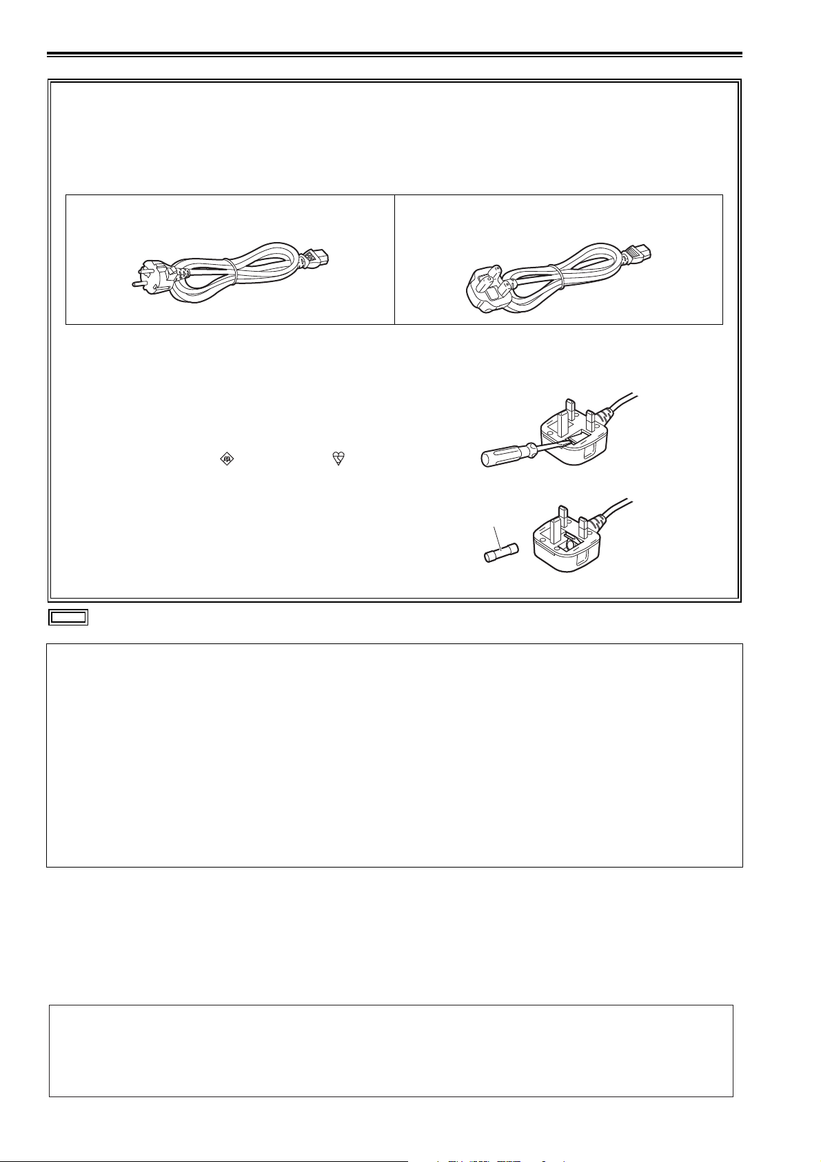
Caution for AC Mains Lead
FOR YOUR SAFETY PLEASE READ THE FOLLOWING TEXT CAREFULLY.
This product is equipped with 2 types of AC mains cable. One is for continental Europe, etc. and the other one is only for U.K.
Appropriate mains cable must be used in each local area, since the other type of mains cable is not suitable.
FOR U.K. ONLY
This appliance is supplied with a moulded three pin
mains plug for your safety and convenience.
A 13 amp fuse is fitted in this plug.
Should the fuse need to be replaced please ensure that
the replacement fuse has a rating of 13 amps and that it
is approved by ASTA or BSI to BS1362.
Check for the ASTA mark or the BSI mark on the
body of the fuse.
If the plug contains a removable fuse cover you must
ensure that it is refitted when the fuse is replaced.
If you lose the fuse cover the plug must not be used until
a replacement cover is obtained.
A replacement fuse cover can be purchased from your
local Panasonic Dealer.
How to replace the fuse
1.Open the fuse compartment with a screwdriver.
2.Replace the fuse.
FOR CONTINENTAL EUROPE, ETC.
Not to be used in the U.K.
FOR U.K. ONLY
Fuse
indicates safety information.
Note regarding the Power Management function specified under COMMISSION REGULATION (EC)
No 1275/2008 implementing Directive 2009/125/EC of the European Parliament and of the Council.
This device is designed and manufactured for use at a broadcasting station and/or in a similar environment.
This device is not equipped with a Power Management function or the Power Management function is set to OFF as it will
prevent the device from fulfilling its intended purpose for the reasons below.
1. If the device is a Studio Camera, a Weather Camera, a Mixer or other processor:
A Power Management function may cause the device to suddenly stop during recording or while On Air.
2. If the device is a Studio Monitor:
A Power Management function may cause video for the confirmation of whether a signal is normal, or whether the signal
has been lost, to be un-viewable.
3. If the device is a Camera Recorder:
A professional camera recorder must be able to start quickly at any time, but a Power Management function will cause an
increase in the time taken to resume from Stand-by mode.
EEE Yönetmeliğine Uygundur.
EEE Complies with Directive of Turkey.
Manufactured by: Panasonic Corporation, Osaka, Japan
Importer’s name and address of pursuant to EU rules:
Panasonic Testing Centre
Panasonic Marketing Europe GmbH
Winsbergring 15, 22525 Hamburg, Germany
Read this first! (For AJ-PD500E):
6
Page 7

Read this first! (For AJ-PD500E)
Read this first! (For AJ-PD500E) (continued)
EMC NOTICE FOR THE PURCHASER/USER OF THE APPARATUS
1. Applicable standards and operating environment (AJ-PD500E)
The apparatus is compliant with:
• standards EN55103-1 and EN55103-2, and
• electromagnetic environments E1, E2, E3 and E4
2. Pre-requisite conditions to achieving compliance with the above standards
<1> Peripheral equipment to be connected to the apparatus and special connecting cables
• The purchaser/user is urged to use only equipment which has been recommended by us as
peripheral equipment to be connected to the apparatus.
• The purchaser/user is urged to use only the connecting cables described below.
<2> For the connecting cables, use shielded cables which suit the intended purpose of the
apparatus.
• Video signal connecting cables
Use double shielded coaxial cables, which are designed for 75-ohm type high-frequency applications,
for SDI (Serial Digital Interface).
Coaxial cables, which are designed for 75-ohm type high-frequency applications, are recommended
for analog video signals.
• Audio signal connecting cables
If your apparatus supports AES/EBU serial digital audio signals, use cables designed for AES/EBU.
Use shielded cables, which provide quality performance for high-frequency transmission applications,
for analog audio signals.
• Other connecting cables (IEEE1394, USB)
Use shielded cables, which provide quality performance for high-frequency applications, as
connecting cables.
• When connecting to the DVI signal terminal, use a cable with a ferrite core.
• If your apparatus is supplied with ferrite core(s), they must be attached on cable(s) following
instructions in this manual.
3. Performance level
The performance level of the apparatus is equivalent to or better than the performance level required by
these standards.
However, the apparatus may be adversely affected by interference if it is being used in an EMC environment,
such as an area where strong electromagnetic fields are generated (by the presence of signal transmission
towers, cellular phones, etc.). In order to minimize the adverse effects of the interference on the apparatus in
cases like this, it is recommended that the following steps be taken with the apparatus being affected and
with its operating environment:
1. Place the apparatus at a distance from the source of the interference.
2. Change the direction of the apparatus.
3. Change the connection method used for the apparatus.
4. Connect the apparatus to another power outlet where the power is not shared by any other
appliances.
To remove the battery
Back-up Battery (Lithium Battery)
• For the removal of the battery for disposal at the end of its service life, please consult your dealer.
Read this first! (For AJ-PD500E):
7
Page 8

• The SDXC logo is a trademark of SD-3C, LLC.
• HDMI, the HDMI logo, and High-Definition Multimedia Interface are trademarks or registered trademarks of HDMI Licensing
LLC in the United States and/or other countries.
•Microsoft
®
and Windows® are registered trademarks or trademarks of Microsoft Corporation in the United States and/or other
countries.
• QuickTime and the QuickTime logo are trademarks or registered trademarks of Apple Inc., used under license therefrom.
• Apple, Mac, Mac OS, MacBook, iPhone, iPod touch, iPad, QuickTime, and Safari are registered trademarks of Apple Inc. in
the United States and/or other countries.
• Microsoft product screenshots are used in accordance with the guidelines of Microsoft Corporation.
• Other company names and product names appearing in this manual are trademarks or registered trademarks of their respective owners.
Illustrations in this manual
• Illustrations of the recorder unit and menu screens may appear different from the actual recorder unit and menu screens.
Page references
• In this manual, page references are indicated as: (➝ “½½½” page ½½).
Terminology
• An SD memory card, SDHC memory card, and SDXC memory card are all referred to as an “SD memory card.”
• A memory card with the “P2” logo (for example, the separately sold AJ-P2E064FGN) is referred to as a “P2 memory card.”
• A memory card with the “microP2” logo (for example, the separately sold AJ P2M032AGN) is referred to as a “microP2 memory card.”
• A P2 memory card and microP2 memory card are referred to as a “P2 card.”
Furthermore, a P2 memory card slot and microP2 memory card slot are referred to as a “P2 card slot.”
• Recording with the system frequency at 23.98 Hz or 24 Hz is referred to as “native recording.”
• In this manual, the following operating system is referred to as “Windows 7.”
- Microsoft
®
Windows® 7 operating system
• In this manual, the following operating system is referred to as “Windows 8.”
- Microsoft
®
Windows® 8 operating system
• A recordable media device such as an external hard disk drive connected to a USB port is referred to as a “storage device.”
• Video created by a single recording operation is referred to as a “clip.”
• Orange button labels on the unit panel indicate alternate functions enabled by holding down the SHIFT button. The operating
instructions refer to the buttons only by label, without mentioning the SHIFT button.
Proxy recording with this product
This product is licensed under the AVC Patent Portfolio license for personal and non-commercial use, and is not licensed for
any activity except those for personal use described below.
• Recording video compliant with the AVC standard (hereinafter referred to as an AVC video).
• Playing AVC video recorded by a consumer engaged in a personal and non-commercial activity.
• Playing AVC video that was obtained from a licensed provider.
For details, refer to the MPEG LA, LLC website (http://www.mpegla.com).
Website URL
http://pro-av.panasonic.net/
About copyrights
• Copyright laws may prohibit use, except for personal pleasure, of your recorded video and audio content without permission
of the rights holder.
8
Page 9

Contents
Read this first! (For AJ-PD500P) ..................... 2
Read this first! (For AJ-PD500E) ..................... 5
Usage Precautions .........................................10
Regarding this unit ..............................................10
Before Use ..........................................................12
Always confirm the year, month, day, time, and time
zone, and set as necessary ................................12
Compatible storage media ........................................12
Driver installation .......................................................12
Accessories and Options................................13
Accessories ...............................................................13
Options ......................................................................13
Control Reference Guide................................14
Controls ...............................................................14
Slots and Other Parts ..........................................16
I/O Connectors ....................................................17
Preparation .....................................................20
How to Turn On/Off the Power ............................20
Turning On the Power ...............................................20
Turning Off the Power ...............................................20
Auto Power Off during Operation ..............................20
Setting the Year, Month, Day, and Time .............21
P2 Cards .............................................................22
P2 Card Access Lamp and P2 Card Status ..............22
P2 Card Recording Times .........................................22
Handling of Recording Data ................................24
Using SD/SDHC/SDXC Memory Cards ..............25
Available Modes .............................................26
Deleting Clips on the FTP Server ..............................60
Viewing FTP Server Clip Information ........................ 60
Transferring Clips .....................................................60
Transferring SD Memory Card Data .........................62
USB Device Mode ..........................................64
AVCHD Playback Mode .................................65
Using an Optional AVCHD Board .......................65
SD/SDHC/SDXC Memory Cards ............................... 65
Operating the AVCHD Thumbnail Screen ................66
Setting Playback ......................................................69
Playing Back AVCHD Clips ......................................70
Handling of SD Memory Card Recording Data ... 73
Screen Display ...............................................74
OSD Display ....................................................... 74
Deck Information (DIAG) Display .......................75
Waveform Monitor (WFM) Display ..................... 76
Time Code, User Bits, and CTL......................77
Time code .................................................................77
User Bits ...................................................................77
CTL ...........................................................................77
Setting the Time Code and User Bits ....................... 77
Setup Menu ....................................................79
Menu Operations ................................................ 79
Menu Structure ................................................... 80
Menu List ............................................................ 82
CLIP .......................................................................... 82
REC/PB .....................................................................86
I/F SETUP ..................................................................91
FILE .........................................................................102
SYSTEM ..................................................................105
List of Compatible Input and Output Formats ........ 107
Main Mode......................................................27
Recording/Playback Screen ................................27
Recording Clips ........................................................27
Playing Back Clips ....................................................30
Thumbnail Screen ...............................................32
Displaying the Thumbnail Screen. ............................32
Names and Functions of the Parts of the Thumbnail
Screen .................................................................33
Changing the Thumbnail Display ..............................35
Playing Back Clips ....................................................36
Selecting and Deselecting Clips ...............................38
Adding Text Memos and Shot Marks ........................38
Copying Clips ............................................................39
Deleting Clips ............................................................40
Repairing and Reconnecting Clips ...........................40
Viewing and Editing the Clip Information ..................41
Changing Thumbnails ...............................................42
Adding Metadata to Clips During Recording ............43
Formatting P2 Cards and SD Memory Cards ...........45
Checking the Card Status .........................................45
Manual and Automatic CPS Authentication ..............46
Connecting an External Device via the USB HOST
Port ......................................................................47
Using the Unit Connected to a Network ..............56
Network Settings .......................................................56
Using FTP Client Functions .......................................58
Viewing the Thumbnails of Clips on an FTP Server
(FTP Thumbnail Screen) ......................................59
Using a Keyboard .........................................108
Full Keyboard .......................................................... 108
Numeric Keyboard ..................................................108
USB Keyboard ........................................................108
For Long and Trouble-Free Operation..........109
Maintenance ..................................................... 109
Condensation ................................................... 109
Storage Precautions ......................................... 109
Warning System ............................................... 110
Warning Details ....................................................... 110
Error Codes ............................................................. 111
Updating the Firmware in This Unit ........................ 118
Specifications ...............................................119
Index.............................................................122
9
Page 10

Usage Precautions
Regarding this unit
Panasonic makes no guarantees regarding re-
cordings
• Please note that Panasonic makes no guarantees regarding
recordings in cases where images and/or audio were not recorded as you intended due to problems with this unit or P2
cards.
Be careful to avoid getting water inside the unit
when using it in rainy or snowy weather, or near
the sea shore.
• The unit or a card may be damaged. (In some cases, it may
become unrepairable.)
Do not install this unit in a location exposed to
direct sunlight
• The cabinet may be deformed and the LCD screen may be
damaged.
Keep the unit away from electromagnetic devic-
es (such as TVs and video game consoles).
• Using the unit on or near a TV may result in distorted images
or audio due to electromagnetic radiation.
• The strong magnetic field produced by loudspeakers and
large monitors may damage recordings or distort images.
• Electromagnetic waves from microcomputers may
adversely affect the unit or distort images and audio.
• If an electromagnetic device adversely affects the unit and
results in it becoming unable to be operated correctly, turn
the unit off and disconnect the AC cable from the outlet.
Then, reconnect the AC cable. Finally, turn the unit back on.
Do not use the unit near a radio transmitter or
high-voltage equipment.
• Use near a radio transmitter or high-voltage equipment may
adversely affect recorded images and audio.
When using the unit at the sea shore, in the open
air, etc., be careful not to get sand or dust inside.
• The sand or dust may damage the unit or a card. (Be especially careful when inserting and removing cards.)
When carrying the unit, be careful not to drop it.
• A strong impact may damage the unit and result in it becoming unable to be operated correctly.
Do not get insecticides or other volatile materi-
als on the unit.
• The unit may be deformed and the paint may peel off if insecticides or other volatile materials get on the unit.
• Do not leave the unit in contact with rubber or vinyl products
for long periods.
Notes on the disposal or transfer of memory
cards and storage devices
The format and delete functions on this unit or a PC will only
change the file management data and will leave the data on
the memory card or storage device intact. It is recommended
that cards or storage devices either be physically destroyed
or that commercially available software be used to completely
delete any data they contain. Management of data on memory
cards and storage devices is the sole responsibility of the user.
LCD
• The pixels of the LCD monitor are controlled to obtain high
precision with 99.99 % of the effective pixels. This leaves
less than 0.01 % of pixels that may not light or may remain
on all the time. This is normal and will have no effect on the
images you shoot.
• There may be some unevenness on the screen depending
on the image displayed.
• Wiping or rubbing the LCD screen with a rough cloth may
damage it.
• A temporary afterimage (burn-in) may occur when the same
image or text is displayed for a long time, although it can be
recovered by turning the power off for several hours.
• LCD response and brightness vary with operating temperature.
• In a high-temperature and high-humidity location, the LCD
panel characteristics may change and result in uneven image quality.
Notes on using the network function
Please note that Panasonic makes no guarantees regarding
damage resulting from incorrectly configuring the network
settings to use the network function. Furthermore, please also
note that Panasonic is not liable to pay compensation for any
damages arising from the use of this function.
Usage Precautions: Regarding this unit
10
Page 11
Usage Precautions
Notes on security
*1: Please note that this extended warranty is not available in some countries/regions. *2: Not all models eligible for extended warranty coverage.
*3: The basic warranty period may vary depending on the country/region. *4: Not all repair work is covered by this extended warranty.
*5: The maximum warranty period may be adjusted depending on the number of hours the device has been used.
1st year 2nd year 3rd year 4th year 5th year
*
5
P2HD device
*
2
Basic warranty
*
3
Extended warranty repair
*
4
Purchase
P2 product
Register online
within 1 month
“Registration Notice”
e-mail sent
Details about user registration and the extended warranty: http://panasonic.biz/sav/pass_e
Free 5 years of Warranty Repairs
Customers who register as users on the website will receive an extended warranty repair valid for up to
five years.
P2HD 5 Year Warranty Repair Program*
1
Thank you for purchasing this Panasonic P2HD device.
Register as a user for this device to receive a special service warranty up to five years of free warranty repairs.
Make sure to save the “Registration Notice” e-mail
during the warranty period.
Please note, this is a site that is not maintained by Panasonic Canada Inc. The Panasonic Canada Inc. privacy policy does not apply and is not applicable in relation to any
information submitted. This link is provided to you for convenience.
If you use the network function of this product, there is the likelihood of being subjected to the following damage.
• Leakage of personal information via this product
• Unauthorized operation of this product by a third party with
malicious intent
• Interference or stoppage of this product by a third party with
malicious intent
Be sure to implement sufficient security measures for PCs and
mobile devices.
• Set a password to limit the users who can log in.
• Use a password that is as difficult to guess as possible.
• Change the password regularly.
• Panasonic and its affiliate companies would never directly
inquire about a password. In the event that somebody does
make a direct inquiry, do not let the person know the password.
• Prior to the repair, maintenance, disposal, or transfer of this
product, initialize the network settings to prevent the leakage of information.
Information on software for this product
1. This product includes software licensed under the GNU General Public License (GPL) and GNU Lesser General Public License (LGPL), and users are hereby informed that they have the right to obtain, modify, and redistribute the source code
of this software.
2. This product includes software licensed under the MIT-License.
3. This product includes software developed by the OpenSSL Project for use in the OpenSSL Toolkit (http://www.openssl.org/).
4. This product includes software licensed under the OpenBSD License.
5. This product includes PHP, freely available from <http://www.php.net/>.
6. This software is based in part on the work of the Independent JPEG Group.
This information is provided on the installation CD-ROM supplied with the unit. Please refer to the LDOC folder. (The documents are in English.)
For details on obtaining the source code, see the Panasonic website (➝ “Website URL” on page 8).
Users are requested to refrain from making any inquiries about the source code they have obtained.
Usage Precautions: Regarding this unit
11
Page 12

Before Use
Always confirm the year, month, day, time, and time zone, and set as necessary
The clock setting affects the management of recorded content and playback order. Before recording, set and confirm the year,
month, day, time, and time zone settings.
(➝ “Setting the Year, Month, Day, and Time” page 21)
Compatible storage media
The following types of storage media can be used. See the specified pages for details.
Recording and playback
• P2 memory cards and microP2 memory cards (➝ “P2 Cards” page 22)
Proxy recording, data storage, and AVCHD playback
• SD, SDHC, and SDXC memory cards (➝ “Using SD/SDHC/SDXC Memory Cards” page 25)
Driver installation
Before use, download the necessary drivers from the Panasonic website and install them on the personal computer.
For the installation procedure, refer to installation manual on the Panasonic website.
For the latest information on drivers, refer to the Panasonic website. Refer to (➝ “Website URL” page 8)
Usage Precautions: Before Use
12
Page 13

Accessories and Options
Accessories and Options
Accessories
AC power cord CD-ROM
• AJ-PD500P • AJ-PD500E
(For the U.K.) (For areas other than the U.K.)
• Operating instructions
• After unpacking, dispose of the AC power cord caps and packing materials properly.
Options
• AVCHD codec board (AJ-YCX500G)
Note:
• Do not use the options with other than the above product.
• For details on installing options, contact your dealer.
Accessories and Options:
13
Page 14
Control Reference Guide
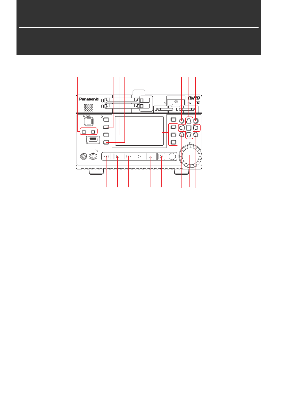
Controls
15 2 3 4 6 20 7 9 8
ヒ
モヶュリヰチロユヷユロ
ンユヤ
ヶヴャチピハパ
ラヰヴヵ
ヱラヰワユヴ ロユヷユロ
ヮヰュユ
ヱャ
ビ
ンユヮヰヵユ
ヤヰヶワヵユン
ンユヴユヵ
ヵヤチヱンユヴユヵ
ヴヵヰヱ
ンユヸ ョョ
ヱロモヺ ヱモヶヴユ ンユヤ ヴユモンヤラ
ピ
フ
ヵラヶヮャワモリロ
ュリヴヱロモヺ
ヶヴユン ヴユヵ
ヒフ
ユヹリヵ ヮユワヶ
ビブ
ヤモワヤユロ
ピプ
ヵヰヱ ヴラリョヵ
ャヰヵヵヰヮ
ュリモヨ
ルヰヨ
ヱンユヷ ワユヹヵ
12 13 14 15 16 17 18 11 19 10
About button labels: Orange labels indicate alternate functions enabled by simultaneously pressing the [SHIFT] button.
<Example> Press the [SHIFT] and [REMOTE/MODE] buttons simultaneously to execute the [MODE] button function.
1. REMOTE, MODE button
[REMOTE] button:
This button switches to the mode for controlling the unit
from the REMOTE connector.
When the unit can be controlled from the REMOTE connector, the lamp on the left is lit.
[MODE] button:
This button switches to USB device mode (USB DEVICE)
or AVCHD playback mode.
(➝ “USB Device Mode” page 64, “AVCHD Playback
Mode” page 65)
2. COUNTER button
This button switches the counter display in the following
order.
TC➝UB➝CTL➝TC
(➝ “Time Code, User Bits, and CTL” page 77)
5. AUDIO LEVEL buttons
[AUDIO LEVEL-REC] button:
This button displays the recording audio level adjustment
screen.
(➝ “Recording Clips” page 27)
[AUDIO LEVEL-PB] button:
This button displays the playback audio level adjustment
screen.
(➝ “Playing Back Clips” page 30)
6. USER 1-3, 4-6 buttons
Users can assign any functions to these buttons.
(➝ “USER BUTTON” page 99)
7. THUMBNAIL button
This button displays or hides the thumbnail screen.
(➝ “Displaying the Thumbnail Screen.” page 32)
3. RESET button
When the counter display on the display panel is CTL,
press this button to reset the counter display to
“0:00:00:00”.
(➝ “Time Code, User Bits, and CTL” page 77)
4. TC PRESET button
This button sets the TC or UB value.
(➝ “Time Code, User Bits, and CTL” page 77)
Control Reference Guide: Controls
14
8. SHIFT button
Hold this button while pressing another button to perform
the assigned function of that button.
Page 15

Control Reference Guide
9. Cursor control buttons
Up/down/left/right cursor buttons:
• These buttons control the cursor movement for thumbnails, menus, etc.
• Press the up or down cursor button during the display of
playback still images to step one frame forward or back.
(➝ “Frame-by-frame playback” page 31)
• Use the left or right cursor button to switch the audio
channel for recording and playback audio level adjustment.
(➝ “Recording Clips” page 27)
[TOP]/[BOTTOM] buttons:
These buttons move the cursor to the first (TOP) or last
(BOTTOM) thumbnail.
[SET] button:
This button allows you to perform operations such as selecting thumbnails and menu items.
10.MENU, DIAG button
[MENU] button:
This button displays the menu.
[DIAG] button:
When the menu is not displayed, press this button to display the DIAG screen for viewing various conditions.
(➝ “Deck Information (DIAG) Display” page 75)
16.PAUSE button
Press this button during playback to pause (STILL) playback to display a still image.
Press the button while playback is paused to resume playback.
Press the button during recording to switch to the recording standby (PAUSE) state.
Press the button in the recording standby state to resume
recording.
17.REC button
This button allows you to check video and audio in EE
mode during playback image output. With the exception of
when playback is stopped, pressing this button activates
EE mode, which remains active until you press another
button.
EE mode monitoring is only available when the playback
video format matches the setting in the “LINE&FREQ” (➝
page 105) menu item.
Press this button and the [PLAY] button simultaneously to start recording.
Press this button and the [PAUSE] button simultaneously to switch to the recording standby state. Remote recording from a camera can be enabled from the menu.
Set remote recording in the “AUTO REC” (➝ page 86)
menu item.
11.EXIT, CANCEL button
[EXIT] button:
This button closes the menu or returns from the storage explorer to normal display.
[CANCEL] button:
This button cancels a selection, stops copying, etc.
12.REW, PREV button
[REW] button:
This button fast rewinds playback.
The speed can be selected in the “FF.REW MAX” (➝ page
87) menu item.
[PREV] button:
This button cues the current or previous clip or the clip and
text memo location during playback.
13.STOP button
This button stops playback or recording.
14.FF, NEXT button
[FF] button:
This button fast forwards playback.
The speed can be selected in the “FF.REW MAX” (➝ page
87) menu item.
[NEXT] button:
This button cues the next clip or the clip and text memo location during playback.
18.SEARCH button
This button switches to search mode.
19.Multi control dial
When in search mode:
Dial for checking video and searching. Each press toggles
between SHTL (shuttle) mode and JOG (jog) mode.
• Operation is in SHTL mode immediately after switching to
search mode.
When adjusting the recording or playback audio level:
The recording or playback audio level can be adjusted by
pressing the [AUDIO LEVEL-REC] or [AUDIO LEVEL-PB]
button and then turning the multi control dial.
(➝ “Recording Clips” page 27, “Playing Back Clips” page
30)
When the thumbnail screen is displayed:
Turning the dial performs the same operation as the left
and right cursor buttons.
Pressing the dial performs the same operation as the
[SET] button.
When the menu is displayed:
Turning the dial performs the same operation as the up
and down cursor buttons.
Pressing the dial performs the same operation as the
[SET] button.
20.DISPLAY button
15.PLAY button
This button starts playback.
(➝ “Playing Back Clips” page 30)
This button switches the display of the OSD to “no display”
➝ “OSD display” ➝ “no display.”
(➝ “Screen Display” page 74)
Control Reference Guide: Controls
15
Page 16

Slots and Other Parts
1326 7 8 9
ヒ
モヶュリヰチロユヷユロ
ンユヤ
ヶヴャチピハパ
ラヰヴヵ
ヱラヰワユヴ ロユヷユロ
ビ
ヮヰュユ
ヤヰヶワヵユン
ヱャ
ヵヤチヱンユヴユヵ
ンユヮヰヵユ
ンユヴユヵ
ンユヸ ョョ
ヴヵヰヱ
ヱンユヷ ワユヹヵ
ヱロモヺ ヱモヶヴユ ンユヤ ヴユモンヤラ
ピ
フ
ヵラヶヮャワモリロ
ュリヴヱロモヺ
ヶヴユン ヴユヵ
ヒフ
ビブ
ヤモワヤユロ
ピプ
ヵヰヱ ヴラリョヵ
ユヹリヵ ヮユワヶ
ュリモヨ
ャヰヵヵヰヮ
ルヰヨ
1. lamp
(➝ “How to Turn On/Off the Power” page 20)
2. button
This button turns the power on or off.
(➝ “How to Turn On/Off the Power” page 20)
3. Speaker
This speaker outputs the monitor audio.
Output from the speaker is disabled when headphones
are connected.
4. PHONES/LEVEL
Headphone jack:
This jack is for connecting stereo headphones to listen to
the sound being recorded or played back with the headphones.
Monitor audio volume adjustment knob:
This knob adjusts the monitor audio volume of the headphones or speaker.
Set whether or not to link the MON L/R output jacks in the
“MONITOR OUT VOL.” (➝ page 95) menu item.
5. USB HOST port (USB 3.0 Type A)
(➝ “Connecting an External Device via the USB HOST
Port” page 47)
Note:
• Use a double-shielded cable to connect to this port.
• Use a USB 3.0 compliant cable to connect USB 3.0 compatible storage devices.
1110111054
6. P2 memory card access lamps
(➝ “P2 Card Access Lamp and P2 Card Status” page 22)
7. P2 memory card slots
(➝ “P2 Cards” page 22)
8. EJECT buttons
(➝ “P2 Cards” page 22)
9. SD/SDHC/SDXC memory card slot and access lamp
Insert an SD/SDHC/SDXC memory card.
Insert the card cut-corner-edge first and label-side up, until the card latches into place.
To remove it, check that the access lamp is not lit green or
flashing orange, then release the latch by gently pushing
the card in again.
Note:
Use an SD/SDHC/SDXC memory card for reading the CPS password, reading and writing menu settings, reading and writing
metadata, proxy recording, and AVCHD playback.
(➝ “Using SD/SDHC/SDXC Memory Cards” page 25)
10.microP2 memory card access lamps
(➝ “P2 Card Access Lamp and P2 Card Status” page 22)
11.microP2 memory card slots
(➝ “P2 Cards” page 22)
Control Reference Guide: Slots and Other Parts
16
Page 17
Control Reference Guide
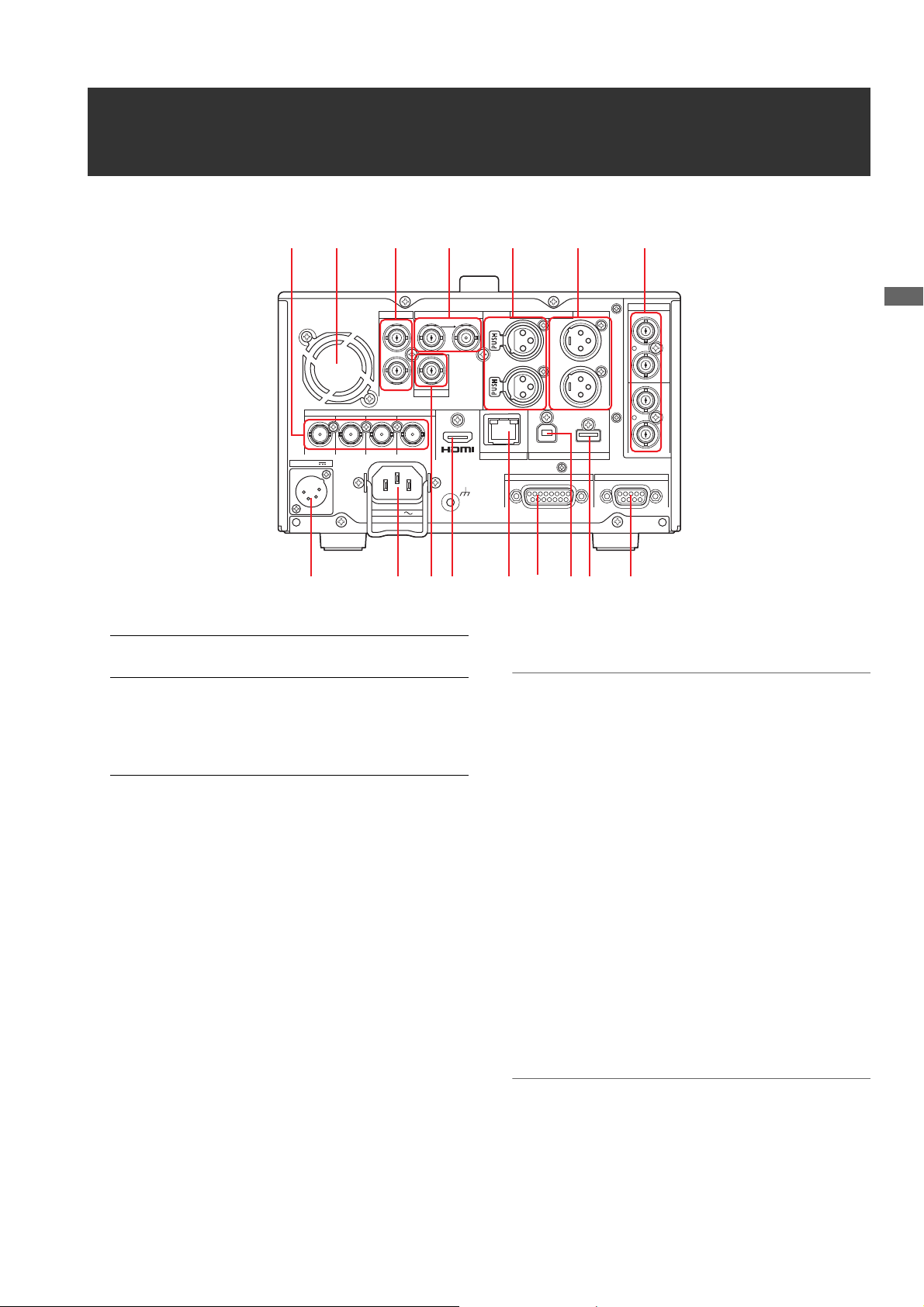
I/O Connectors
616 1 4 2 3 13
ンユヮヰヵユ
モユヴバユャヶ
ヰヶヵ
リワ
ヤラ
ヒバビ
ヤラ
ピバフ
ヤラ
ヒバビ
ヤラ
ピバフ
ヵリヮユチヤヰュユ
リワ
ヰヶヵ
ヴュリ
リワ ヰヶヵチヒ
ュヤチリワ
ヰヶヵチビ
モヤチリワ
ラュバヴュチンユョ モワモロヰヨチモヶュリヰ
ヘブチモヶヵヰ
リワ
ヷリュユヰチヰヶヵ
ヮヰワ
ヴリヨワモロ
ヨワュ
ヰヶヵ
リワ
チチチ
ヒ
ヤラ
ヤラ
チチチ
ビ
ロモワ
チ
ヒバ
ヤラ
チ
ロ
チチ
ビバ
ヤラ
チ
ン
ュユヷリヤユ
ヶヴャチビハパ
ヱモンモロロユロチンユヮヰヵユ
ヰヶヵバヮヰワ
レユヺャヰモンュ
12 11 5 7 14 15 10 9 8
1. TIME CODE IN/OUT Jacks
TIME CODE IN: This jack is for recording an exter-
nal time code onto a P2 card.
TIME CODE OUT: This jack is for outputting the play-
back time code during playback.
It outputs the time code from the
internal time code generator during recording.
2. ANALOG AUDIO IN jacks
These jacks are for inputting analog audio.
3. ANALOG AUDIO OUT/MON output jacks
These jacks are for outputting the audio signals (CH1 to
CH8) selected in the “MONITOR CH” (➝ page 95) menu
setting.
4. REF IN jacks
These jacks are for inputting HD and SD reference video
signals.
Note:
• For an HD reference, input a positive and negative polarity
tri-level sync signal. Input a signal that match the input signal and SYSTEM format.
• For an SD reference, input a black burst signal that complies
with SMPTE ST 170 and ITU624-4.
• Video and audio output signals may be degraded when no
reference video signal is provided. We recommend using
this unit in systems that provide a reference video signal for
input.
• When recording 1080P or 720P without an HD or SD reference input, the data may be recorded with the phase offset
in relation to the input signal.
5. VIDEO OUT jack
This jack is for outputting analog composite video signals.
6. HD/SD-SDI IN/OUT/MON jacks
These jacks are for inputting and outputting serial digital
component audio/video signals.
The output jack for superimposition can be changed in the
“OSD OUTPUT” (➝ page 96) menu setting.
Note:
Use 5C-FB or equivalent double-shielded cables to connect
to these jacks.
Control Reference Guide: I/O Connectors
17
Page 18

7. HDMI OUT port
1
23
4
Connect a monitor or TV using an HDMI cable.
Note:
• This unit does not support VIERA link. Be careful because
connecting it to a VIERA link compatible device with an
HDMI cable may cause VIERA link to malfunction on that device.
• Use a double-shielded cable to connect to this port.
8. REMOTE connector
Connect an external controller to control the unit from the
external device.
Note:
Use a double-shielded cable to connect to this connector.
9. KEYBOARD port (USB 2.0 Type A)
Connect an external USB keyboard to enter metadata and
other data.
(➝ “Using a Keyboard” page 108)
10.USB 2.0 device port
(➝ “USB Device Mode” page 64)
Note:
Use a double-shielded cable to connect to this port.
11.AC IN connector
Use the supplied AC cable to connect to a power outlet.
Note:
When both an AC power supply and external DC power supply are connected, priority is given to supplying power from
the AC power supply.
12.DC IN connector
Connect a 12 V DC power supply.
When the voltage drops to approximately 10.6 V, the unit
is shutdown automatically. (When the “EXT DC IN SELECT” (➝ page 98) menu item is set to “DC PWR SUPPLY”)
Afterwards, the power is not restored automatically even if
the power supply voltage recovers. Press the [ ] button to turn the power on.
Pin No. Signal
1GND
2, 3 -
4 +12 V
DC IN connector
Note:
For the DC cable, use a shielded cable that is shorter than 2
m (78-3/4 inches). Using a DC cable of 2 m (78-3/4 inches) or
longer may result in noise appearing on the screen.
When using an external DC power supply, be sure to check
the external DC power supply ratings and use one that is
suitable for the unit.
Check the pin assignment of the DC output connector
of the external DC power supply and the DC IN connector on the unit, and connect the connectors with the correct polarity. Incorrect connection of the +12 V power
supply to the GND connector may cause a fire or injury.
13.AES / EBU IN / OUT connectors
These connectors are for inputting and outputting digital
audio signals that comply with the AES/EBU standard.
Note:
• The digital audio signals that are input need to be synchronized with the video input signals. If they are not synchronized, the audio output signals will be affected by noise.
• Use double-shielded cables to connect to these connectors.
14.LAN port
This port enables a 1000BASE-T/100BASE-TX/10BASE-T
network connection.
(➝ “Using the Unit Connected to a Network” page 56)
Note:
• Use a shielded cable to connect to this port.
• The orange lamp lights when a LAN link is established. The
green lamp flashes while data is being transferred.
Control Reference Guide: I/O Connectors
18
Page 19

Control Reference Guide
15.PARALLEL REMOTE connector
12345678
9
101112131415
This is a 15-pin parallel remote connector.
The assignment for each port can be selected in the “PARALLEL PORT PORT1-7 PORT 9-14” (➝ page 100 and
page 101) menu item.
Pin
Port Name Function
No.
1 PORT1 Command input port 1
2 PORT2 Command input port 2
3 PORT3 Command input port 3
4 PORT4 Command input port 4
5 PORT5 Command input port 5
6 PORT6 Command input port 6
7 PORT7 Command input port 7
8 +5 V Output
(+180 mA max.)
9 PORT9 Status output port 1
10 PORT10 Status output port 2
11 PORT11 Status output port 3
12 PORT12 Status output port 4
13 PORT13 Status output port 5
14 PORT14 Status output port 6
15 GND GND
Note:
• Supply TTL-level, active LOW electrical signals with an edge
of 100 msec or higher as input signals.
• A maximum open collector and sink current of 6 mA is output as an output signal.
• Use a shielded cable to connect to this connector.
16.Fan
This fan is for cooling the unit. Install the unit where the
ventilation holes will not be blocked.
Note:
If the fan is stopped while the power is on, the “FAN
STOPPED” warning is displayed. The unit will operate even if
the fan is stopped. However, please stop using the unit immediately.
Control Reference Guide: I/O Connectors
19
Page 20

Preparation
ヒ
ピ
ビ
ンユヮヰヵユ
ヤヰヶワヵユン
ンユヤ
モヶュリヰチロユヷユロ
ヱャ
ンユヴユヵ
ヵヤチヱンユヴユヵ
ヶヴャチピハパ
ラヰヴヵ
ヱラヰワユヴ ロユヷユロ
ンユヸ ョョ
ヱンユヷ ワユヹヵ
ヱロモヺ ヱモヶヴユ ンユヤ ヴユモンヤラ
ュリヴヱロモヺ
ヵラヶヮャワモリロ
ヵヰヱ ヴラリョヵ
ヶヴユン ヴユヵ
ユヹリヵ ヮユワヶ
ュリモヨ
ルヰヨ
ヤモワヤユロ
ャヰヵヵヰヮ
ヒフ
ビブ
ピプ
フ
ヮヰュユ
ヴヵヰヱ
ンユヤ
モヶュリヰチロユヷユロ
ヱャ
ヮ
[ ] button
lamp
How to Turn On/Off the Power
Turning On the Power
From the power-off state, press the [ ] button to turn on the power.
After startup, the lamp lights green.
Note:
The following messages appear during startup.
• “STARTING SYSTEM...”: Flashes during startup.
• “AUTO POWER OFF = ¾ min”: The time set in the “AUTO POWER OFF” (➝ page 91) menu item is displayed instead of “½.” When
the menu item setting is set to OFF, this message is not displayed.
Turning Off the Power
From the power-on state, press the [ ] button for at least two seconds to turn off the power.
The lamp flashes during the power-off process, and then turns off.
Auto Power Off during Operation
The unit has a function to automatically turn the power off after a short period of time if no operation such as recording, playback,
copying, or formatting is performed during that time. To resume operation after the power turns off automatically, turn the power
on again.
Note:
• The time until the power turns off can be set in the “AUTO POWER OFF” (➝ page 91) menu item.
Preparation: How to Turn On/Off the Power
20
Page 21
Preparation
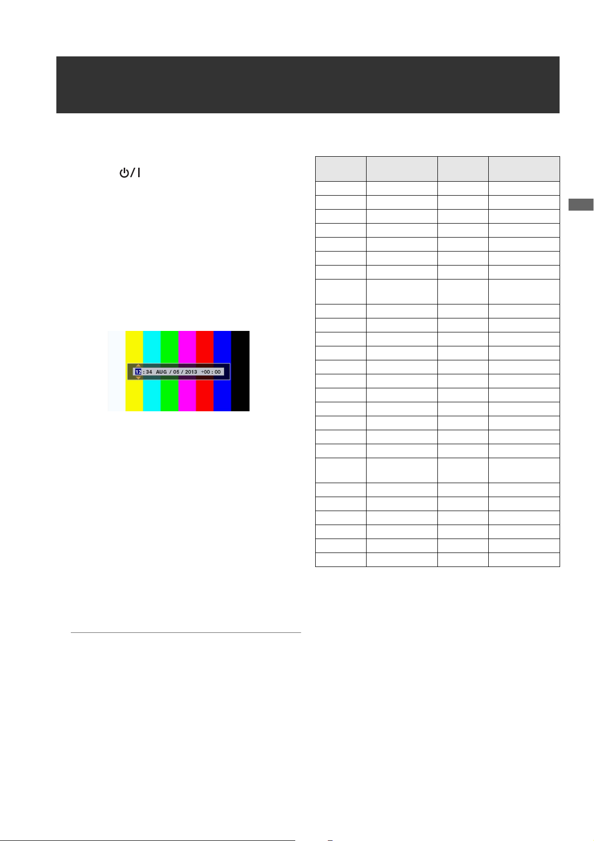
Setting the Year, Month, Day, and Time
Set the clock before using the unit the first time.
1 Press the [ ] button on the unit to turn on the
power.
2 Press the [MENU] button to open the menu.
(➝ “Menu Operations” page 79)
3 Use the cursor buttons to select the “I/F SETUP” -
“CLOCK” (➝ page 91) menu item and then press the
[SET] button.
The clock setting screen appears. The default values are
the current time settings.
4 Use the left and right cursor buttons to select the dig-
its to be set.
• Display is in the order of hour/minute/month/day/year/
time zone.
• For the time zone, set the difference in hours from Greenwich Mean Time.
• The time is displayed in the 24-hour format.
5 Use the up and down cursor buttons to set the year,
month, day, time, and time zone.
Time zone
Time
difference
00:00 Greenwich +01:00 Central Europe
-00:30 +01:30
-01:00 Azores Islands +02:00 Eastern Europe
-01:30 +02:30
-02:00 Mid-Atlantic +03:00 Moscow
-02:30 +03:30 Tehran
-03:00 Buenos Aires +04:00 Abu Dhabi
-03:30 Newfoundland
-04:00 Halifax +05:00 Islamabad
-04:30 +05:30 Bombay
-05:00 New York +06:00 Dacca
-05:30 +06:30 Yangon
-06:00 Chicago +07:00 Bangkok
-06:30 +07:30
-07:00 Denver +08:00 Beijing
-07:30 +08:30
-08:00 Los Angeles +09:00 Tokyo
-08:30 +09:30 Darwin
-09:00 Alaska +10:00 Guam
-09:30 Marquesas
-10:00 Hawaii +11:00 Solomon Islands
-10:30 +11:30 Norfolk Island
-11:00 Midway Island +12:00 New Zealand
-11:30 +12:45 Chatham Islands
-12:00 Kwajalein +13:00
+00:30
Area
Island
Islands
Time
difference
+04:30 Kabul
+10:30 Lord Howe Island
Area
6 After configuring the settings, press the [SET] button.
Pressing the [SET] button sets the clock to the changed
time.
Note:
• The clock is affected by deviation so check that the time is
correct before use.
• When an accurate time is required, check and reset the time
before use.
Preparation: Setting the Year, Month, Day, and Time
21
Page 22

P2 Cards
P2 Card Access Lamp and P2 Card Status
P2 Card Access Lamp P2 Card Status
Lights green Recording possible Both writing and reading are possible.
Lights orange Recording target Writing and reading are enabled and currently recording target.
Flashing orange Card being accessed Writing or reading is in progress.
Fast flashing orange Card being recognized The P2 card is being recognized.
Slow flashing green Card full There is no available space on the P2 card. Only reading is possible.
Write protected The write-protect switch on the P2 card is set to Protect. Only reading is pos-
sible.
Off
Card not supported for recording
Slot not target for recording
Card not supported The card cannot be used with the unit. Replace the card.
Format invalid The P2 card is not formatted properly. Reformat it.
No card A P2 card is not inserted. Waiting for the card to be recognized.
Card cannot be authenticated
No USB access The P2 card is not accessible using USB device mode.
Recording is not possible with the currently set recording format because an
SD memory card or other unsupported card is inserted. To record, change
the recording format or use a P2 card.
A card has been inserted in a different slot from that of "REC MEDIA" (P2/
microP2) (➝ page 87) of the "REC/PB SETUP" menu item.
A micorP2 memory card for which authentication is not possible. Refer to
“Manual and Automatic CPS Authentication” (➝ page 46) and then perform
authentication.
Note:
“FORMAT ERROR!” or “NOT SUPPORTED!” may appear if a microP2 memory card is inserted slowly. Should this happen, reinsert it.
P2 Card Recording Times
P2 cards supported by the unit
The unit supports separately sold P2 memory cards and microP2 memory cards of 4 GB to 64 GB. (As of October 2013)
Note:
• When AVC-Intra100 of 1080/60P and 1080/50P is selected, recording to the following P2 cards is not possible.
- H, R, A, and E series P2 memory cards.
• AJ-P2C002SG (2 GB) cards cannot be used.
• The unit may need to be updated depending on the type of P2 card.
• For the latest information not available in the Operating Instructions, visit the website. (➝ “Website URL” page 8)
Preparation: P2 Cards
22
Page 23

Preparation
P2 card recording times
(Example of using one 64 GB card)
“LINE&FREQ” setting (recording format) “REC FORMAT” setting (codec) Recording duration
1080-59.94P, 1080-50P AVC-I100 Approx. 32 minutes
1
AVC-G25
1080-59.94i, 1080-50i AVC-I100 Approx. 64 minutes
AVC-G25 Approx. 220 minutes
480-59.94i, 576-50i DVCPRO50 Approx. 128 minutes
DVCPRO Approx. 256 minutes
1
*
Support will be provided via a version update in the future.
*
Approx. 110 minutes
Note:
• The recording times for 32 GB, 16 GB, and 8 GB P2 cards are a 1/2, 1/4, and 1/8th of those shown above, respectively.
• The displayed sizes include, for example, the management area so the amount of space available for recording will be less than the
above.
Dividing of clips recorded to P2 cards
When an 8 GB or larger P2 card is used with the unit, continuous recordings longer than the durations shown in the table below
result in automatic division of the recording into multiple clips. However, on a P2 device, such recordings are handled as a
single clip for thumbnail operations (display, delete, repair, etc.). Such recordings may be displayed as separate clips in nonlinear editing software or on a PC or other device.
When recording to a microP2 memory card exceeding 32 GB using the AVC-LongG codec, you can enable continuous recording as the same clip in the “FILE SPLIT” (➝ page 87) menu item.
Recording formats (excluding native recording) Continuous recording duration
AVC-I100 (1080P) Approx. 3 minutes
AVC-I100 (1080i), DVCPRO HD Approx. 5 minutes
AVC-G50, AVC-I50, DVCPRO50 Approx. 10 minutes
AVC-G25, DVCPRO, DV Approx. 20 minutes
Content Protection System (CPS)
microP2 memory cards support the content protection system (CPS), which is a security function that prevents data leakage to
third parties by recording in an encrypted format.
To use the CPS function, you need to set a CPS password and enable the microP2 memory card authentication function (➝
“Manual and Automatic CPS Authentication” page 46) and encrypted format function (➝ “Formatting P2 Cards and SD Memory
Cards” page 45) on the unit. microP2 memory cards in an encrypted format are authenticated automatically to enable use as
microP2 memory cards for recording and playback only on devices for which the same CPS password is set. For details on CPS
passwords, refer to “Manual and Automatic CPS Authentication” (➝ page 46).
Note:
• Up to 16 characters can be set for the password.
• An encrypted microP2 memory card cannot be recognized in an SD slot of a PC.
• If an authentication error occurs, perform authentication again with the correct password, format the card to enable use as storage
media, or eject it from the device. Do not perform any operation other than manual authentication or formatting while a card for which
an authentication error has occurred is inserted.
• To access an encrypted microP2 memory card from a PC when in USB device mode, perform authentication for the microP2 memory
card with P2 Viewer Plus.
Preparation: P2 Cards
23
Page 24

Handling of Recording Data
Drive:\
CONTENTS
LASTCLIP.TXT*
1
AVCLIP
AUDIO
CLIP
ICON
PROXY
VIDEO
VOICE
All of the folders are required.
*
1
This file contains the data for the last clip
recorded on the P2 device.
P2 memory cards and microP2 memory cards are semiconductor memory cards designed for the P2 series, Panasonic’s line
of professional video and broadcast equipment.
Recording data in the P2 format is ideally suited for com-
puter processing because it is a file format. The file structure includes not only video and audio data recorded in
the unique MXF file format but also various important information, and has the folder configuration shown on the
right.
If any of this data is changed or deleted, a problem may occur, such as the data being unable to be recognized as P2
data or the card no longer being able to be used in a P2 device.
A P2 card that has been formatted in other than a microP2
memory card compatible device will not contain the AVCLIP folder. For a P2 card without an AVCLIP folder, the
folder will be created automatically when recording is performed on a microP2 memory card compatible device.
To prevent data loss when transferring the data on a P2
card to a PC or other device or when writing the data stored on a PC back to a P2 card, be sure to use the dedicated P2
Viewer Plus software, which can be downloaded from the Panasonic website.
For the URL, refer to (➝ “Website URL” page 8)
When transferring data to a PC using a general IT tool such as Microsoft Windows Explorer or Apple Finder, observe the fol-
lowing. Be sure to use P2 Viewer Plus to write the data back to a P2 card.
• Process the CONTENTS folder and the LASTCLIP.TXT file together.
Do not modify any data under the CONTENTS folder.
When copying the data, be sure to copy both the CONTENTS folder and the LASTCLIP.TXT file together.
• When transferring the data from multiple P2 cards to a PC, create a separate folder for each P2 card to prevent the overwriting of clips with identical names.
• Do not delete data on a P2 card.
• Be sure to use a P2 device or P2 Viewer Plus to format P2 cards.
Preparation: Handling of Recording Data
24
Page 25

Preparation
Using SD/SDHC/SDXC Memory Cards
Use only SD, SDHC , and SDXC*1 memory cards that comply with the SD, SDHC, and SDXC*3 standards in the unit. Memory
cards other than SD, SDHC, and SDXC cards (for example, MultiMediaCard
1
*
The SDHC memory card is a new card standard (version 2.0), established by the SD Card Association in 2006, for memory
cards with capacities exceeding 2 GB.
2
*
MultiMediaCard (MMC) is a registered trademark of Infineon Technologies AG.
3
*
The SDXC memory card is a new standard (version 3.0), established by the SD Card Association in 2009, for memory cards
with capacities exceeding 32 GB.
• When using a miniSD, miniSDHC, microSD, microSDHC, or microSDXC card in the unit, be sure to use it with the correct dedicated adapter attached. (Note that the unit will not operate normally when only an adaptor without a card is inserted.)
Please note that a miniSD, miniSDHC, microSD, microSDHC, or microSDXC card will not operate normally in the unit when in
AVCHD playback mode, even if the dedicated adapter is attached.
• Be sure to use the unit to format cards.
• The unit supports SD, SDHC, and SDXC memory card of the following sizes.
SD: 8 MB to 2 GB
SDHC: 4 GB to 32 GB
SDXC: Over 32 GB
Use of Panasonic SD, SDHC, and SDXC memory cards and miniSD, miniSDHC, microSD, microSDHC, and microSDXC cards
is recommended.
2
*
) cannot be used.
Note:
When using the AVCHD option, also check “AVCHD Playback Mode” (➝ page 65).
• The latest information on the unit and supported memory cards is available on our P2 Support website.
For the URL, refer to (➝ “Website URL” page 8)
Preparation: Using SD/SDHC/SDXC Memory Cards
25
Page 26

Available Modes
䇭
MODE
䇭
MODE
SET
PLAY
STILL
STOP
PLAY
STILL
STOP
THUMBNAIL
REC
Mode menu
Main mode: Recording and playback
USB device mode: Connecting to PC or other devices
AVCHD playback mode: Playback AVCHD and others (Option)
Recording/
playback screen
Thumbnail
screen
Playback screen
Thumbnail
screen
Playback screen
Note:
• Instalation of AVCHD codec board is reqired. (➝ “Accessories and Options” page 13)
This unit comes with three modes: Main mode, USB device mode, and AVCHD playback mode.
You can select or change the mode by selecting one of the menu items displayed when you press the MODE button. Main mode
has a thumbnail screen for displaying and managing clip thumbnails and playing clips and a recording/playback screen for
recording and playback.
The figure below shows an overview of each mode.
• Recording/playback screen: Displays video, time code, and other information and enables recording and playback.
• Thumbnail screen: Displays clip thumbnails, various properties, and other information and enables the management and
playback of clips.
Available Modes:
26
Page 27

Main Mode
Main Mode
ョョ
ワユヹヵ
ヮユヮヰンヺチヤモンュチンユヤヰンュユ
ヱロモヺ ヱモヶヴユ ンユヤヴヵヰヱ
23
フ
1
2
Recording/Playback Screen
Use the recording/playback screen for the following.
• Recording to P2 cards
• Playing back all cards in the order they were recorded
Recording Clips
Record audio and video as clips.
Recording clips
Before you start recording, set the recording frequency, format, slot for recording, input signal, and other settings in the
menu.
(➝ Setup Menu “SYSTEM MODE” page 105, “REC/PB” page
86)
Note:
If analog is selected for audio input, an 8-channel audio file (may
be 4 channels depending on the format) will be created but no
sound will be recorded on any channel other than channels 1 and
2.
Adjusting the recording audio levels
Follow the procedure below to change the volume level for recording.
1. Press the [AUDIO LEVEL-REC] button.
The recording volume appears.
2. Turn the multi control dial.
The levels of all channels can be adjusted.
Note:
Operation is also possible with the up and down cursor buttons.
3. Use the left or right cursor button to select an audio
channel.
The selected channel number flashes. Each of the channels can be adjusted.
4. After adjustment is finished, press the [AUDIO LEV-
EL - REC] button or [EXIT] button.
The setting values are saved and the displayed information disappears.
Note:
• The setting values do not change when you turn off the power.
• If you press the [RESET] button during the changing of the
audio levels, the default values are restored.
1 Insert a P2 card.
2 Press the [PLAY] button while holding down the
[REC] button.
Recording begins on the P2 card in the slot with the access lamp is lit orange.
Note:
Setting the “PROXY SETUP” - “REC MEDIA” (➝ page 88)
menu item to “P2” or “P2&SD” and then recording will start
proxy recording simultaneously with the recording of the main
material. (➝ “Proxy recording” page 29)
3 Press the [STOP] button to stop recording.
Note:
Recording to a mixture of the P2 memory card slots (1 and 2)
and microP2 memory cards slots (3 and 4) is not possible. Select the recording target slots in the “REC/PB SETUP” - “REC
MEDIA” (➝ page 87) menu item.
Changing the recording slot
The recording target slot can be changed during recording or
when recording is stopped.
ヵラヶヮャワモリロ
ュリヴヱロモヺ
ヶヴユン ヴユヵ
ヒフ
ビブ
ピプ
ヵヰヱ ヴラリョヵ
ユヹリヵ ヮユワヶ
ャヰヵヵヰヮ
ヤモワヤユロ
ュリモヨ
ルヰヨ
1. Assign the SLOT SEL function to a [USER] button in
the “USER BUTTON” (➝ page 99) menu item.
2. Press the [USER] button during recording or when
recording is stopped.
The recording slot changes with each press of the button.
Note:
• When you do not perform SLOT SELECT right after switching
the recording target P2 card, “SLOT SEL INVALID” will appear on the third line of the OSD if the “OSD TC SELECT” (➝
page 96) menu item is set to “T&S&M.”
• The slots that can be switched with the SLOT SEL function
are limited to those selected in the “REC/PB SETUP” - “REC
MEDIA” (➝ page 87) menu item.
Main Mode: Recording/Playback Screen
27
Page 28

Various types of recording
Canceling loop recording mode
• Select “NORMAL” in the “RECORDING” menu item.
Hot swap recording
When P2 cards are inserted into both of the two P2 memory
card slots or microP2 memory card slots specified in the
“REC/PB SETUP” - “REC MEDIA” (➝ page 87) menu item, you
can make one continuous recording that spans two cards.
You can also record continuously on three or more cards (hot
swap recording) by replacing one card while recording on the
other.
Note:
• P2 card recognition may be delayed and prevent hot swap recording depending on the timing at which a P2 card is inserted
in the empty slot (immediately prior to or after recording continues onto the other card).
It is recommended to insert a P2 card when there is still at least
1 minute of time left on the card currently being used for recording.
• The unit does not support hot-swapping during playback.
LOOP REC
LOOP REC is a function that records continuously while successively switching the card target for recording when two P2
cards are inserted in the P2 memory card slots or microP2
memory card slots. Recording can be performed continuously
by returning to the first card when the available space on the
P2 cards has been used up and then overwriting the old recording with the new recording.
To use the LOOP REC function, select “LOOP” in the “RECORDING” (➝ page 86) menu item.
AUTO REC
When a camera compatible with the function is connected via
HD SDI, starting and stopping recording on the unit can be
automatically controlled using the REC START / STOP function on the camera.
1. Match the “AUTO REC” (➝ page 86) menu item to
the camera to be used.
2. Press the [REC] button and [PAUSE] button
on the unit simultaneously to switch to REC PAUSE
mode.
3. Press the [REMOTE] button to set REMOTE.
Now you can start and stop recording on the unit using the
REC START / STOP function on the camera.
Note:
• Use P2 cards with at least one minute of free space for loop recording.
• During loop recording, all of the P2 card access lamps for the
P2 cards used for recording are lit orange. Note that removing
any of the P2 cards will stop loop recording.
When “LOOP” is selected in the “RECORDING” menu item
• "LOOP" is displayed on the second line of the OSD. However,
even when “LOOP” is selected in “RECORDING,” the loop recording will not work if only one card is inserted or the remaining
recording time on a card is less than 1 minute. Should this happen, “LOOP” will flash on the OSD.
• The remaining space of P2 cards is indicated as the standard
guaranteed recording time according to the recording format.
When loop recording is stopped right after deleting old data, the
actual remaining time may be shorter than indicated.
• Proxy recording cannot be performed.
During loop recording
• Shot marks cannot be added or deleted. Also, text memos cannot be added.
• Support for using the loop recording function when the “REC
FORMAT” setting value is “AVC-G50” or “AVC-G25” is planned
to be provided at a later date via a version upgrade.
Main Mode: Recording/Playback Screen
28
Page 29

Main Mode
Proxy recording
Simultaneously record video as well as time-code data and other real-time data in MPEG4 format or H.264 format to a P2 card
or SD memory card separately from the main video and audio material recorded with the unit.
(➝ “PROXY SETUP” page 88 menu item)
Recording modes and recording signals (video and audio)
Video Audio
Recording mode
STD 2CH MP4
LOW 2CH MOV
HQ 2CH MOV 640 x 360
HQ 4CH MOV 640 x 360
SHQ 2CH MOV 960 x 540
Resolution Codec Bit rate Codec
320 x 240
(QVGA)
1080i mode
480 x 270
1080 60/50p mode
320 x 180
MPEG-4
Simple Profile
H.264
Baseline Profile
H.264
High Profile
H.264
High Profile
H.264
High Profile
1500 kbps AAC-LC 2 channels 64 kbps
800 kbps AAC-LC 2 channels 64 kbps
1500 kbps AAC-LC 2 channels 64 kbps
1500 kbps AAC-LC 4 channels 64 kbps
3500 kbps Linear PCM 2 channels 768 kbps
Number of chan-
nels
Bit rate per channel
Recording proxy data
Set the “PROXY SETUP” - “REC MEDIA” (➝ page 88) menu
item to “P2” or “P2&SD” and then press the [PLAY] button
while holding down the [REC] button to start proxy recording simultaneously with the recording of the main material.
• You can check detailed information on the recorded proxy
data from the properties of the clip.
(➝ “Viewing the clip metadata information” page 41)
• Proxy data is recorded to a P2 card or SD memory card as
a video and audio file and a real-time data file.
Video and audio file:
½½½½½½½½.MP4 or ½½½½½½½½.MOV
Real-time metadata file: ½½½½½½½½.BIN
The time code, user bits, and UMID information are recorded on a frame basis.
Note:
• When recording proxy data to an SD memory card, use an SD
memory card of class 2 or above.
• The SD memory card access lamp lights green during the re-
cording of proxy data to the SD memory card.
• If short recordings are repeated, the available recording time
may decrease significantly compared to the available space.
• Check the number of clips recorded to the SD memory card in
“NUMBER OF CLIP” of the “SD CARD PROPERTY” (➝ page
102) menu item. When the number of clips becomes 1,000 or
more, proxy data cannot be recorded to the SD memory card
even if there is free space remaining.
• Shot marks and text memos cannot be added to clips in an SD
memory card.
• Even if you delete the clips recorded to the P2 card in the
thumbnail screen, the proxy data recorded to the SD memory
card will not be deleted.
• Proxy recording cannot be performed during loop recording.
Checking proxy data
• The indicator is displayed for a clip of material for which
proxy data recording was performed.
• Check the proxy data in P2 Viewer Plus. The data may not
be able to be checked depending on the version of P2
Viewer Plus. For information on P2 Viewer Plus, visit the Panasonic website. (➝ “Website URL” page 8)
• Proxy data cannot be played with the unit.
Main Mode: Recording/Playback Screen
29
Page 30
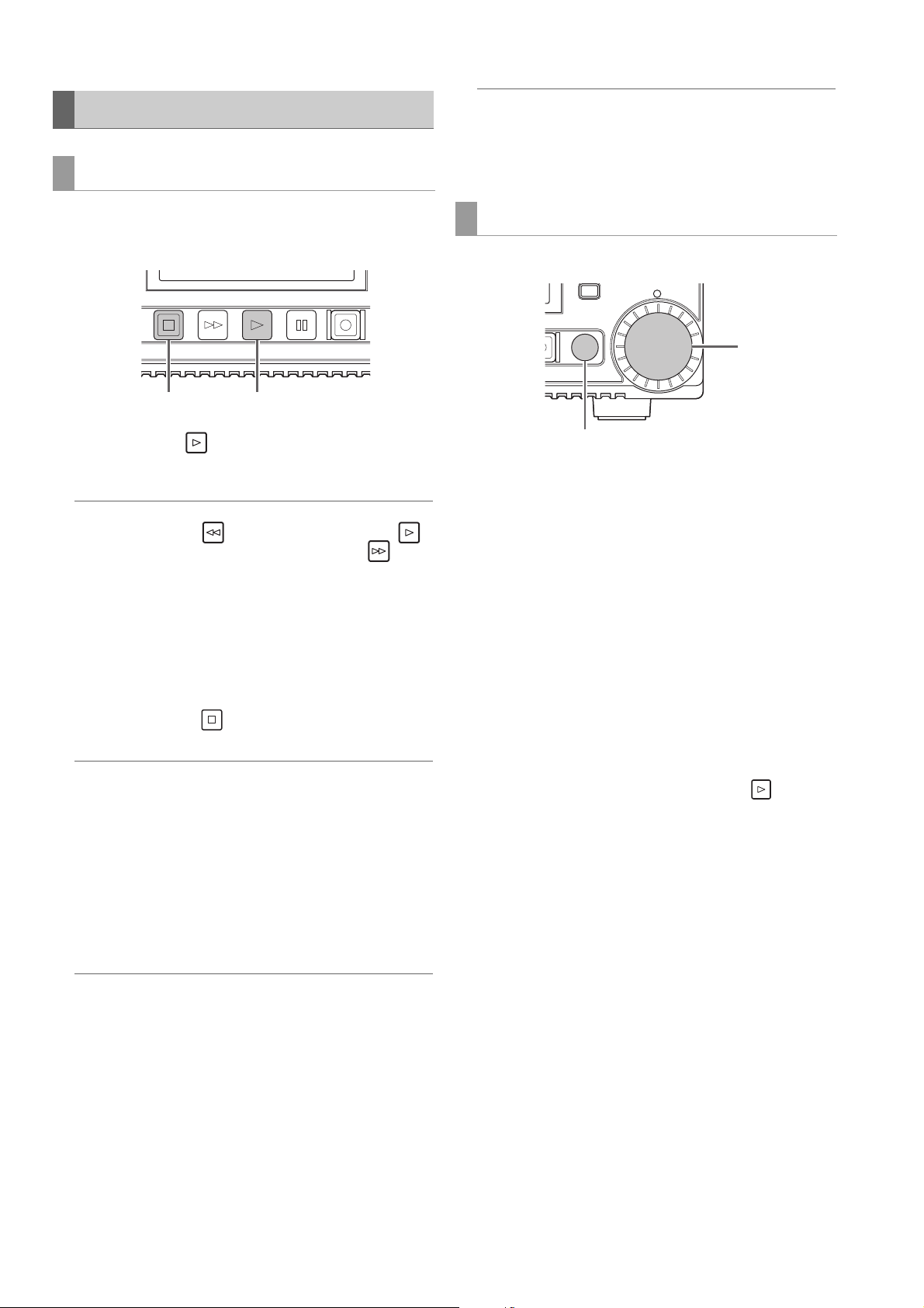
Playing Back Clips
ョョ
ワユヹヵ
ヱロモヺ ヱモヶヴユ ンユヤヴヵヰヱ
12
2
Playback
Note:
• The setting values do not change when you turn off the power.
• If you press the multi control dial during the changing of the
volume levels, the default values are restored.
Before you start playback, set the playback frequency, format, and other settings in the menu. (➝ Setup Menu “SYSTEM
MODE” page 105)
1 Press the [PLAY] button.
Playback begins. Clips play back in the order they were
recorded.
Note:
• Pressing the [REW] button instead of the [PLAY]
button rewinds playback, while pressing the [FF] button
fast forwards playback.
• Video and audio playback may be disrupted between clips
in different video formats (1080i, 1080p, etc.) or compression formats.
• When clips with the same video format but different audio bit
rates are played back continuously, the audio between clips
will be muted.
2 Press the [STOP] button.
Playback stops and the input video (EE) is displayed.
Note:
To show the image where playback stopped (PB image), set
the “STOP EE SEL” (➝ page 87) menu item to “PB.”
Adjusting the playback audio levels
Follow the procedure below to change the playback levels.
1. Press the [AUDIO LEVEL-PB] button.
The playback volume appears.
Variable speed playback
The playback speed can be varied to search for a scene.
ピプ
ヴユモンヤラ
ルヰヨ
1
1 Press the [SEARCH] button during STOP/STILL/
PLAY.
The mode becomes STILL (SHTL 0.0) and a still image is
output.
2 Turn the multi control dial to change the playback
speed.
The speed changes in accordance with how much the dial
is turned.
• Audio is not played back at speeds faster than 10 times normal speed.
• Turning the dial clockwise changes the speed in the forward direction and turning it counterclockwise changes the
speed in the backward direction.
• Press the [PAUSE] button to set the speed to the 0 state. To
return to normal playback, press the [PLAY] button.
• When the multi control dial is pressed in variable speed
mode, the JOG lamp lights and the mode becomes JOG
mode. Variable playback is performed in accordance with
the speed at which the dial is turned.
2. Turn the multi control dial.
The levels of all channels can be adjusted.
Note:
Operation is also possible with the up and down cursor buttons.
3. Use the left or right cursor button to select an audio
channel.
The selected channel number flashes. Each of the channels can be adjusted.
4. After adjustment is finished, press the [AUDIO LEV-
EL - PB] button or [EXIT] button.
The setting values are saved and the displayed information disappears.
Main Mode: Recording/Playback Screen
30
Page 31

Main Mode
ョョ ヱロモヺ ヱモヶヴユ ンユヤ ヴユモンヤラ
ュリヴヱロモヺ
ヵラヶヮャワモリロ
ヵヰヱ ヴラリョヵ
ヶヴユン ヴユヵ
ユヹリヵ ヮユワヶ
ュリモヨ
ルヰヨ
ヤモワヤユロ
ャヰヵヵヰヮ
ヒフ
ビブ
ピプ
ヴヵヰヱ
2
1
Frame-by-frame playback
1 Press the [PAUSE] button, [SEARCH] button,
and [STOP] button (when “STOP EE SEL” - “PB”
is set) to switch to still image mode.
2 Press the up or down cursor button.
• The up cursor button performs frame-by-frame playback
in the forward direction and the down cursor button performs frame-by-frame playback in the backward direction.
• Holding down a cursor button performs continuous
frame-by-frame playback. To return to normal playback,
press the [PLAY] button.
Repeat playback
Play back playable clips repeatedly.
1 Press [MENU].
2 Set the “REPEAT PLAY” (➝ page 86) menu item to
“ON.”
3 Close the menu.
4 Press the [PLAY] button to start playback.
All clips are played repeatedly.
• Repeat playback continues until the [STOP] button
is pressed.
• Repeat playback is not performed during playback other
than normal playback, for example, variable playback,
and playback stops at the beginning (BOS) or end (EOS)
of a playable clip.
• During repeat playback, “REPEAT PLAY” is displayed for
the operating status on the OSD.
One clip playback (ONE CLIP PLAY)
1 Assign the “ONE CLIP PLAY” function to a [USER]
button in the “USER BUTTON” menu.
(➝ Setup Menu “USER BUTTON” page 99)
2 Press the [PAUSE] button while a thumbnail is
displayed or from the thumbnail display screen and
then press the [USER] button with “ONE CLIP PLAY”
assigned when in still image mode.
• Only the clip at the cursor position or current position is
played.
• Only STOP is enabled during this playback.
Note:
One clip playback is also performed when the [PLAY]
button is pressed while holding down the [SHIFT] button.
Clip and text memo forward/rewind
1 Switch to playback or a still image or other image dis-
play state.
2 Press the [PREV] button or [NEXT] button.
The clip beginning or text memo position is located in accordance with the “SEEK POS SEL” (➝ page 87) menu item.
Main Mode: Recording/Playback Screen
31
Page 32

Thumbnail Screen
2
This unit has a thumbnail screen for managing clips. A “clip” consists of a set of video, audio, and additional information such
as metadata, and a “shot” is a clip generated by a single normal start-to-stop recording operation. A shot that spans multiple
P2 cards is handled as one clip.
The thumbnail screen displays a list of thumbnails of recorded clips. You can perform the following clip management operations
while checking these thumbnails.
• Playback of clips on P2 cards
• Simple playback of clips on a storage device
• Copying and deleting clips
• Adding text memos to clips
• Checking and deleting text memos
• Viewing and deleting shot marks
• Formatting P2 cards
• Viewing clip properties
• Viewing P2 card status
Note:
• Thumbnails are generated from only a sample of the recorded video. Therefore, they appear coarser than the actual video.
• The menu items for thumbnails can be set when the thumbnail screen is displayed.
Displaying the Thumbnail Screen.
ヵラヶヮャワモリロ
ヺ
ンヴユヵ
フ
ブ
ヵヰヱ ヴラリョヵ
ユヹリヵ ヮユワヶ
ャヰヵヵヰヮ
ヤモワヤユロ
ュリモヨ
1 Press the [ ] button on the unit to turn on the
power.
Note:
If “THUMBNAIL” is selected in the “POWER ON GUI” (➝ page
91) menu item, the thumbnail screen will appear at power-on.
2 Press the [THUMBNAIL] button.
The thumbnail screen appears on the LCD monitor.
Press the [THUMBNAIL] button again to close the thumbnail screen and return to the record/playback screen (video).
Note:
In the “OSD OUTPUT” (➝ page 96) menu item, you can select
output to VIDEO OUT, SDI MON OUT, HDMI OUT, SDI OUT,
etc.
Main Mode: Thumbnail Screen
32
Page 33

Main Mode
Names and Functions of the Parts of the Thumbnail Screen
171
16 21
98 10 1112 13
1. Display status
The following information is displayed on the screen.
ALL: All clips
SAME FORMAT: Clips with the same format as the
system
SELECT: Clips selected with the [SET] but-
ton
MARKER: Clips with shot markers added
TEXT MEMO: Clips with text memo data added
SLOT n: Clips on the P2 card in slot No. n
P2 / REMAIN: Media information (amount of re-
maining free space)
P2 / USED: Media information (amount of
space used)
META DATA: Set metadata
Procedures for switching between displays
(➝ “Changing the Thumbnail Display” page 35)
2. Recording mode
Indicates the recording mode of the clip at the cursor position.
20
19
7
6
543218
4. Duration
Indicates the length (duration) of the clip at the cursor position and the rough current playback position in relation to
the length of the clip.
Playback position display is enabled when “RESUME” is
selected in the “PB POSITION” (➝ page 84) menu item.
When the playback start position is not the beginning of
the clip, the rough current playback position is indicated.
5. Number of selected clips
Indicates the number of selected clips and the total number of clips.
6. Clip information display
One of the following is indicated: TC (time code) , UB (user bits) at the start of clip recording , time of shooting, day
of shooting , date and time of shooting , clip name , user
clip name , and slot number.
(➝ “Changing the Thumbnail Display” page 35)
7. Thumbnail
Shows the thumbnail recorded for each clip. You can use
the EXCH.THUMBNAIL function to change this thumbnail.
(➝ “Changing the Thumbnail Display” page 35)
14
15
3. System format
Indicates the recording format of the clip at the cursor position.
8. Clip number
Indicates the numbers assigned to P2 card clips, which
are normally assigned in order from the earliest shooting
date. For a clip that cannot be played back, the clip number is red and the unplayable indicator is displayed. You
can change the order in which clips appear using the
function for displaying clips in the order of selection or the
SORT function.
(➝ “Changing the Thumbnail Display” page 35)
9. Shot mark indicator
Indicates that a shot mark has been added to the clip.
Main Mode: Thumbnail Screen
33
Page 34

10. Proxy indicator
Indicates that proxy data has been additionally recorded
for the clip.
11. Text memo indicator
Indicates that text memo data has been added to the clip.
16.P2 card slot and storage device or LAN status indi-
cation
Indicates the P2 card and storage device or LAN connection status as shown below.
12. Edit copy indicator
Indicates an edit-copied clip.
13. Wide indicator
Indicates a clip recorded at an angle of view of 16:9. However, this is not indicated for an HD format clip.
14. Incomplete clip indicator
Indicates that the clip spans multiple P2 cards but one of
the cards that contains part of the clip has not been inserted.
15. Bad clip and Unknown clip indicator
Indicates a clip that became defective because the power
was turned off during recording or was damaged for some
other reason. Clips with the yellow bad clip (
can sometimes be repaired.
(➝ “Repairing bad clips” page 40)
Clips with the red clip indicator
and should be deleted. If deleting is not possible, format
the P2 card.
When a clip is not, for example, in the P2 standard format,
is displayed instead of .
() cannot be repaired
) indicator
to
(White)
(Yellow)
(Gray)
(White)
(Yellow)
(Red)
The numbers of P2 card slots that contain P2
cards are indicated in white.
The number of the P2 card slot of the P2 card
that contains the clip at the cursor position is
indicated in yellow. When a clip spans multiple P2 cards, the numbers of all the slots with
cards that contain the clip are indicated.
Note:
For an inserted P2 card such as the following,
the slot number has a red frame.
• “RUNDOWN CARD”
A P2 card for which the maximum number of
overwrites has been exceeded.
• “DIR ENTRY NG CARD”
A P2 card with an unsupported directory
structure.
• “AUTH NG CARD”
A microP2 memory card for which the CPS
password cannot be authenticated.
Gray indicates that a storage device is not
connected.
White indicates that a storage device is
available.
Yellow indicates that the clips on a storage
device are displayed as thumbnails.
Red indicates that a storage device is
connected but is not available.
Gray indicates that the LAN setting is OFF.
Main Mode: Thumbnail Screen
34
(Gray)
(White)
(Yellow)
(Red)
White indicates that the LAN setting is ON.
Yellow indicates that a LAN cable is
connected and that there is a link.
Red indicates an error with the unit. Consult
your dealer because the unit may have
malfunctioned.
Page 35

Main Mode
17.Status message
Displays a message indicating the processing status. For
example, the “UPDATING” text message and a rotating
icon are displayed during screen updating.
18.Simple property indication
Displays the properties of the clip at the cursor position.
This is displayed when the “THUMBNAIL SIZE” (➝ page
84) menu item is set to “SMALL.”
You can select the information to display from the menu.
(➝ “Setting the items to display as properties” page 36)
Note:
When there are more characters than can be displayed, only
the range of characters that can be displayed are shown.
19.Thumbnail scroll bar
Indicates the location of the currently displayed thumbnail
among all of the thumbnails.
20. Unplayable indicator
Indicates a clip that cannot be played because, for example, the frequency differs from that of the system.
21.DC input voltage indication
Indicates the input voltage value when the “EXT DC IN SELECT” (➝ page 98) menu item is set to other than “DC
PWR SUPPLY.”
When other than “DC PWR SUPPLY” is set, the DC voltage
value is indicated even with AC power supply input.
Setting the thumbnails to display
1 Use the cursor buttons to align the cursor with the
type of clips you want to display in the “REPOSI-
TION” (➝ page 82) menu item.
2 Press the [SET] button.
Setting the thumbnail size
1 Use the cursor buttons to align the cursor with the
size of thumbnails you want to display in the
“THUMBNAIL SIZE” (➝ page 84) menu item.
2 Press the [SET] button.
Setting the display of clip information
The display of clip information can be customized according
to purpose.
1 Use the cursor buttons to align the cursor with the
item you want to set in the “DATA DISPLAY” (➝ page
84) menu item.
Changing the Thumbnail Display
The thumbnail screen can be customized according to the operating conditions to improve efficiency.
Example:
• Set the settings of the “THUMBNAIL SETUP” (➝ page 84)
menu item as shown below.
Set “INDICATOR” to “ALL HIDE”
Set “DATA DISPLAY” to “CLIP NAME”
Set “THUMBNAIL SIZE” to “LARGE”
• Set the “REPOSITION” (➝ page 82) menu item to “SELECTED CLIPS”.
Figure showing the thumbnail screen display example
2 Press the [SET] button.
Note:
The thumbnail and OSD output destinations can be switched in
“OSD OUTPUT” (➝ page 96).
Main Mode: Thumbnail Screen
35
Page 36

Setting the items to display as properties
1
2
Set the simplified property display items to display on the left
side of a thumbnail.
1 Use the cursor buttons to align the cursor with the
“PROPERTY DISP.” (➝ page 85) menu item.
Playing Back Clips
Playback
ュリヴヱロモヺ
ヵラヶヮャワモリロ
ヵヰヱ ヴラリョヵ
2 Press the [SET] button to open the item menu.
All selected items are indicated by check marks.
3 Press the [SET] button to add a check mark for an
item you want to display.
Pressing the [SET] button adds a check mark to an unchecked item and clears the check mark from a checked
item.
Note:
• Up to six items can be displayed simultaneously.
• When the sixth item has been selected, no other unchecked
item can be selected. Clearing the check mark from a
checked item allows you to select another item.
ヶヴユン ヴユヵ
ヒフ
ユヹリヵ ヮユワヶ
ビブ
ヤモワヤユロ
ピプ
ヱロモヺ ヱモヶヴユ ンユヤ ヴユモンヤラ
ャヰヵヵヰヮ
ュリモヨ
ルヰヨ
1 Use the cursor buttons to align the cursor with the clip
you want to play.
2 Press the [PLAY] button.
Playback begins from the clip at the cursor position. After
the clip at the cursor position has been played, the subsequent clips are played back in order. When the last clip
has been played, the thumbnail screen reappears.
Note:
• To play back a clip, you do not need to select it (so that the
thumbnail appears inside a blue frame).
• You can change the thumbnail display settings to play back
clips only from specified slots or play back only clips with
text memos added.
• You can change the order that clips are played back.
1 Select the clips in the order you want them to be played
back.
2 Select [SELECTED CLIPS] in the “REPOSITION” (➝ page
82) menu item to switch the thumbnail display to only the
selected clips (in the order they were selected).
• Pressing the [PAUSE] button instead of the [PLAY]
button displays the first frame of the clip as a still image.
• A clip whose clip number is red cannot be played back.
• Pressing the [REW] button instead of the [PLAY]
button rewinds playback, while pressing the [FF] button
fast forwards playback.
Main Mode: Thumbnail Screen
36
Page 37

Main Mode
Thumbnail
display
Blue indicates selected
number of text memo clips
and white indicates total
number of text memo clips.
Indicates still images
included with the text
memos.
• Pressing the [STOP] button during clip playback stops
playback and redisplays the thumbnail screen.
• When playback is stopped, the cursor moves to the clip
played prior to stopping.
• Video and audio playback may be disrupted between clips
in different video formats (1080i, 1080p, etc.) or compression formats.
• When clips with the same video format but different audio bit
rates are played back continuously, the audio between clips
will be muted.
• Changing the thumbnail screen to text memo display allows
you to start playback from a text memo position.
• You can select the playback start position for playback from
thumbnails in the “PB POSITION” (➝ page 84) menu item.
Playing back one clip (ONE CLIP PLAY)
When “ONE CLIP PLAY” is assigned to a [USER] button,
pressing the [USER] button plays only the clip at the cursor
position.(➝ “USER BUTTON” page 99)
Note:
• When the thumbnail screen is redisplayed after one clip playback ends, the cursor moves to the next clip.
• All buttons except the [STOP] button are disabled during
one clip playback.
• One clip playback starts from the position set in the “PB POSITION” (➝ page 84) menu item.
• When JOG/SHTL is used to display a still image during playback from the thumbnail screen, the [USER] button to which
“ONE CLIP PLAY” has been assigned allows you to play to the
end of the clip from the position of the still image.
• One clip playback is also performed when the [PLAY] button is pressed while holding down the [SHIFT] button.
Note:
• When a text memo clip with different settings for the “SYSTEM MODE” (➝ page 105) menu item is displayed,
may be displayed instead of the thumbnail for the text memo
position displayed at the bottom.
2 Select the clip with a text memo that you want play
and press the [SET] button.
The cursor moves to the bottom of the LCD monitor.
Using variable speed playback and frameby-frame playback
Operation is the same as in the recording/playback screen.
(➝ “Variable speed playback” page 30, “Frame-by-frame
playback” page 31)
Playing back from a text memo position
1 Select “TEXT MEMO CLIPS” in the “REPOSITION”
(➝ page 82) menu item.
The thumbnails of clips with text memos are displayed at
the top of the LCD monitor. Information on the clip text
memo selected with the cursor is displayed at the bottom
of the LCD monitor.
The cursor moves.
3 When the cursor is at the bottom, use the left or right
cursor button to align the cursor with the thumbnail
with a text memo that you want to play and then
press the [PLAY] button.
The clip is played back from the time code position of the
text memo selected with the cursor. When you press the
[STOP] button to stop playback or when playback
stops upon reaching the end of the clip, the thumbnail
screen reappears and the cursor returns to the thumbnail
of the text memo where playback was started. Press the
[EXIT] button to return the cursor to the top of the thumbnail screen.
Note:
All buttons except the [STOP] button are disabled during
playback.
Main Mode: Thumbnail Screen
37
Page 38

Selecting and Deselecting Clips
Adding Text Memos and Shot Marks
Select the clips you want to process on the thumbnail screen.
Selecting clips
1 Use the cursor buttons to align the yellow frame (cur-
sor) with the target clip.
Note:
Press the [TOP] or [BOTTOM] button to move the cursor to the
first or last clip.
2 Press the [SET] button.
A light blue frame and 9 appear on the clip selected with
the cursor to indicate that it is selected.
Note:
• Repeat steps 1 and 2 to select multiple clips.
• Select a clip, move the cursor to another clip, and press the
[SET] button while holding down the [SHIFT] button to select
all of the clips from the clip selected first to the cursor position.
• Selecting a clip updates the number of selected clips indicated at the bottom right of the screen.
A text memo can be added to a clip to mark a specific location
of the clip. You can also add a shot mark to a clip to distinguish it from other clips. A text memo or shot mark cannot be
added to a clip on a P2 card with the write-protect switch set
to Protect.
Adding text memos
When a text memo is added, you can display a thumbnail at
the text memo position for playback or copying and seek
(move to) the text memo position by pressing the [NEXT] or
[PREV] button during video playback.
(➝ Setup Menu “SEEK POS SEL” page 87)
1
Assign “TEXT MEMO” to any [USER] button.
It is assigned to USER3 by default.
(➝ Setup Menu “USER BUTTON” page 99)
2 Press the [USER] button to which “TEXT MEMO” has
been assigned during recording, playback, or thumb-
nail display.
• Press this button during recording or playback to add a
text memo at the position the button was pressed. The
OSD displays “TEXT MEMO” (when successful) or “INVALID” (when adding was not possible).
• Pressing this button when the thumbnail screen is displayed adds a text memo at the position of the clip
thumbnail (normally the beginning).
Note:
• Up to 100 text memos can be added to one clip.
• Pressing the [USER] button to which “TEXT MEMO” has
been assigned during playback may temporarily freeze the
playback screen. This is normal and not a malfunction.
• Text memos cannot be recorded during loop recording.
Deselecting clips
1 Align the cursor with a selected clip and press the
[SET] button again.
The selection is canceled.
Note:
Press the [CANCEL] button to deselect all of the selected
clips.
Main Mode: Thumbnail Screen
38
Deleting text memos
Changing the thumbnail screen to the text memo display allows you to delete text memos.
1 Change the thumbnail screen to the text memo dis-
play.
Select “TEXT MEMO CLIPS” in the “REPOSITION” (➝
page 82) menu item.
2 Use the cursor buttons to move to the thumbnail for
which you want to delete the text memo and press
the [SET] button.
The cursor moves to the bottom.
Page 39

Main Mode
3 After pressing the [SET] button to select the thumb-
nail for which you want to delete the text memo,
press the [SET] button in the “DELETE” (➝ page 82)
menu item.
When “DELETE” is assigned to a [USER] button, you can
also perform the delete operation by pressing the [USER]
button instead of making a menu selection.
4 Select “YES” in the confirmation message.
The text memo is deleted.
2 Align the cursor with the copy destination in the list of
the “COPY” (➝ page 83) menu item and press the
[SET] button.
• When multiple clips are selected, the number of selected
clips is indicated when you press the [SET] button.
• When the copy destination is a storage device (➝ “Connecting an External Device via the USB HOST Port” page
47), select the details of the copy destination.
• When “COPY” is assigned to a [USER] button, you can
also perform the copy operation by pressing the [USER]
button instead of making a menu selection.
Adding shot marks
If you add a shot mark, you will be able to distinguish the clip
from other clips because the mark will be displayed.
1 Assign “MARKER” to any [USER] button.
It is assigned to USER6 by default.
(➝ Setup Menu “USER BUTTON” page 99)
2 Use the cursor buttons to align the cursor with the tar-
get clip.
3 Press the [USER] button to which “MARKER” has
been assigned.
Each press of this button turns the shot mark indicator on/
off.
Note:
• A shot mark is added to a clip even if the button is pressed
in the recording/playback screen.
• When adding or deleting shot marks for a clip that spans
multiple P2 cards, be sure to insert all of the P2 cards that
the clip is recorded on.
• Shot marks cannot be added or deleted during loop recording.
3 Align the cursor with “YES” in the confirmation mes-
sage and press the [SET] button.
Copying of the clip begins.
Note:
• To stop copying, press the [SET] or [CANCEL] button to
cancel the operation. Partially copied clips at the copy destination are deleted.
• When the same clip (clip with the same GLOBAL CLIP ID)
exists in the copy destination because, for example, it has
been copied previously, “OVERWRITE” appears. Select
“YES” to overwrite or “NO” to cancel copying and press the
[SET] button.
4 When the completion message appears, press the
[SET] button.
Copying Clips
Clips can be copied to P2 cards or a storage device connected via USB.
Note:
• Do not turn off the power or remove/insert a card during copying. Doing so may result in a bad clip.
• If a bad clip is created, delete it and perform copying again.
• Reconnect incomplete clips before copying.
1 Select a clip to copy.
Note:
• Copying is not performed when any of the following error
messages appear.
- “LACK OF CAPACITY”
Copying failed because there is insufficient space at the
copy destination.
- “UNKNOWN CONTENTS FORMAT!”
Copying failed because the selected clips include bad
clips.
- “NO COPY TO SAME CARD!”
Copying failed because an attempt was made to copy to
the same card.
- “TOO MANY CLIPS!”
Copying failed because too many clips were selected.
• When copying is performed while a text memo is selected in
the text memo display at the bottom, the selected text memo
position and the section to the next text memo is copied.
When there is no text memo after the selected text memo,
the section from the selected text memo to the end of the clip
is copied.
Main Mode: Thumbnail Screen
39
Page 40

Deleting Clips Repairing and Reconnecting Clips
Use the following procedure to delete unnecessary clips from
a P2 card.
1 Select the clip to delete.
2 Use the cursor buttons to align the cursor with the
“DELETE” (➝ page 82) menu item and press the
[SET] button.
3 Align the cursor with “YES” in the confirmation mes-
sage and press the [SET] button.
All of the selected clips are deleted.
Note:
• When “DELETE” is assigned to a [USER] button, you can
also perform the delete operation by pressing the [USER]
button instead of making a menu selection.
• To stop deletion, press the [SET] or [CANCEL] button to
cancel the operation. Partially deleted clips cannot be restored by canceling.
Repairing bad clips
The bad indicator (yellow ) is displayed for any clip with a problem caused by, for example, a sudden power outage during recording. Use the following procedure to repair clips with problems.
1 Select the bad clip to repair.
2 Use the cursor buttons to align the cursor with the
“REPAIR” (➝ page 83) menu item and press the
[SET] button.
3 Align the cursor with “YES” in the confirmation mes-
sage and press the [SET] button.
Select “NO” to not repair the clip.
Note:
Some clips are so badly damaged they cannot be repaired.
Such clips are indicated by a red indicator ( ).
Reconnecting incomplete clips
A clip that is recorded on multiple P2 cards may become an
incomplete clip ( indicator) due to not being recognized as
a continuous clip. When this happens, you can use the reconnection function to reconnect the continuous clip segments to
restore the original clip.
Note:
• Incomplete clips occur under the following conditions.
- When the segments of a continuous clip that are recorded on
multiple P2 cards are copied separately for each P2 card.
- When the segments of a continuous clip that are recorded on
multiple cards are copied separately for each card to a storage device and then written back to the P2 cards.
1 Select the incomplete clips to reconnect.
Note:
Normally, the thumbnails with the incomplete clip indicator
( ) are grouped together.
2
Use the cursor buttons to align the cursor with the “RE-
CONNECT” (
[SET] button.
➝
page 83) menu item and press the
Main Mode: Thumbnail Screen
40
3 Align the cursor with “YES” in the confirmation mes-
sage and press the [SET] button.
Select “NO” to not reconnect the clip segments.
Note:
When some but not all the clip segments in a clip that consists
of three or more clip segments are reconnected, the incomplete clip indicator ( ) will remain displayed.
Page 41

Main Mode
2)
4)
1)
3)
5)
Viewing and Editing the Clip Information
Viewing the clip metadata information
The detailed information of a clip can be displayed and
checked on a screen.
1 Use the cursor buttons to align the cursor with the tar-
get clip.
2 Use the cursor buttons to align the cursor with the
“CLIP PROPERTY” (➝ page 82) menu item and
press the [SET] button.
The information on the selected clip appears.
1)Clip number
2)Thumbnail
3)Information added to clips
Displays various indicators inserted in the clip and the
number of text memos added to the clip. The mark
is also displayed if the P2 card containing the clip is
write protected.
4)Clip information
The following information is displayed.
CLIP NAME: Clip name
START TC: Time code at start of recording
START UB: User bit value at start of recording
DATE: Date recorded
TIME: Time at start of recording
DURATION: Clip length
V_FORMAT: Clip recording format
FRAME RATE: Playback frame rate
REC RATE: Recording frame rate
5)Clip metadata
Displays the items for viewing detailed information (clip
metadata) on the clip.
3 View the clip metadata if necessary.
Use the cursor buttons to align the cursor with a metadata
item and press the [SET] button to display the following information.
GLOBAL
CLIP ID:
USER CLIP
NAME:
VIDEO: Video signal system
AUDIO: Audio channel system and other infor-
ACCESS: The date of the last update and other
DEVICE: Manufacturer, serial number, and
SHOOT: Date when recording started and end-
SCENARIO: Program name, scene number, and
NEWS: Reporter, purpose, and object
MEMO: Text memo number, OFFSET, PER-
THUMBNAIL: Frame position (normally, start: 0) of
Global clip ID
(This is a unique number, and there is
no clip anywhere in the world with the
same number.)
The clip name the user assigns. This
normally includes the GLOBAL CLIP
ID.
(FRAME RATE, PULL DOWN, ASPECT
RATIO)
mation
(SAMPLING RATE, BIT RATE)
information
(CREATOR, CREATION DATE, LAST
UPDATE DATE, LAST UPDATE PERSON)
model name of the recording device.
ed, etc.
(SHOOTER, START DATE, END
DATE, ALTITUDE, LONGITUDE, LAT-
ITUDE, SOURCE, PLACE NAME)
other information
(PROGRAM NAME, SCENE NO.,
TAKE NO.)
SON, TEXT
Note:
• The position is indicated by the number
of frames from the start.
• Up to 1000 characters of text can be
added, but only the first 500 characters
will be displayed.
• Use the left or right cursor buttons to
move text numbers.
the image used for the thumbnail and
the thumbnail size (width, height)
Main Mode: Thumbnail Screen
41
Page 42

PROXY: Detailed information on proxy data
(Format, video codec, video frame
rate, video bit rate, video resolution,
aspect ratio, TC superimposition on
video, audio codec, audio bit rate,
sampling rate, and number of channels)
Note:
• The bold items are clip metadata that can be changed.
Changing clip metadata
Clip metadata can be changed.
1 Display the clip metadata.
Note:
• To delete the latitude and longitude, enter a blank space for
the altitude. They cannot be deleted separately.
• The metadata of an incomplete clip with the indicator
cannot be changed. Insert the P2 card(s) containing the remainder of the clip.
• The MEMO item cannot be changed if a memo of 100 characters or more has been added.
5 Press the [EXIT] button to end the process.
Changing Thumbnails
A thumbnail can be changed to the image at a position with a
text memo added.
2 Use the cursor buttons to align the cursor with the
metadata you want to edit and press the [SET] but-
ton.
The data that can be edited is indicated as “TEXT,” like in
the figure below.
3 Use the cursor buttons to move to the item you want
to change and press the [SET] button.
The screen for changing the metadata appears.
(➝ “Using a Keyboard” page 108)
1 Add a text memo to the video you want to change.
(➝ “Adding text memos” page 38)
2 Change the thumbnail display to the text memo dis-
play.
Select “TEXT MEMO CLIPS” in the “REPOSITION” (➝
page 82) menu item.
3 Use the cursor buttons to move to the thumbnail to be
changed and press the [SET] button.
The cursor moves to the bottom.
4 Use the left or right cursor button to move to the
thumbnail you want to change.
5 Press the [MENU] button.
6 Use the cursor buttons to align the cursor with the
“EXCH. THUMBNAIL” (➝ page 83) menu item and
press the [SET] button.
4 After you finish making changes, select “OK.”
The changes made to the metadata are saved to the clip
and the metadata display reappears.
Select [EXIT] to cancel the changes and return to the previous display.
Main Mode: Thumbnail Screen
42
7 Align the cursor with “YES” in the confirmation mes-
sage and press the [SET] button.
The menu closes and the thumbnail is changed.
Note:
• You can view the change in the thumbnail position (number
of frames from the beginning) in the THUMBNAIL item of the
clip information display. The thumbnail of a normal first
frame is indicated as 0.
• Even if a thumbnail is changed, playback from the thumbnail
screen will be from the beginning of the clip.
• When a text memo clip with different settings for the “SYSTEM MODE” (➝ page 105) menu item is displayed,
may be displayed instead of the thumbnail for the text memo
position displayed at the bottom.
Page 43

Main Mode
Adding Metadata to Clips During Recording
A metadata upload file containing the shooter name, reporter
name, shooting location, text memo, and other information
can be saved to an SD memory card, and then recorded as
clip metadata by loading it in advance prior to recording.
Use P2 Viewer Plus
to create a metadata upload file
Save the file to an SD memory card
Load the metadata upload file to the unit
When video is recorded, the metadata
will be added to the resulting clip
Preparing a metadata upload file
Use P2 Viewer Plus to a create metadata upload file on a PC.
P2 Viewer Plus is application software for using a personal
computer to process clips recorded on a P2 card that can be
download free of charge from the Panasonic website. For the
URL, refer to “Website URL” (➝ page 8).
Install P2 Viewer Plus on a PC and then create a metadata upload file and write it to an SD memory card.
Note:
• Use the latest version of the P2 Viewer Plus.
• For details on how to create a metadata upload file, refer to the
help function in P2 Viewer Plus.
• Write the metadata upload file to an SD memory card formatted
with the unit.
(➝ “Formatting P2 Cards and SD Memory Cards” page 45)
Selecting the recording method of USER CLIP
NAME
Set the type of data to record as “USER CLIP NAME” in the
“USER CLIP NAME” (➝ page 90) menu item.
The data recorded varies depending on the combination of
the “USER CLIP NAME” and “RECORD” menu items.
Recording method USER CLIP NAME to be recorded
Clip metadata
“RECORD” = “ON”
Clip metadata
“RECORD” = “OFF”
Counter value
The counter value is indicated as a four-digit number. When
the recording method of USER CLIP NAME is set to “TYPE2”
and a metadata file is loaded, the counter value is incremented by 1 each time recording is performed to generate a new
clip.
You can use the following procedure to reset the counter value.
TYPE1: Loaded metadata set-
tings
TYPE2: Loaded metadata set-
tings + counter value
TYPE1: Same as GLOBAL CLIP
ID
TYPE2: Same as CLIP NAME
1. Use the cursor buttons to align the cursor with “USER
CLIP NAME” in the metadata screen of the “REC
META DATA” - “PROPERTY” (➝ page 90) menu
item and press the [SET] button.
2. Use the cursor buttons to align the cursor with
“COUNT RESET” and press the [SET] button.
The counter value is reset to 1.
Settings for adding metadata
Metadata recording setting
Set whether to add loaded metadata when recording clips in
the “REC META DATA” - “RECORD” (➝ page 90) menu item.
3. Press the [EXIT] button to end the process.
Main Mode: Thumbnail Screen
43
Page 44

Metadata upload files
Loading a file
Use the following procedure to load the metadata settings
from an SD memory card.
1. Insert the SD memory card containing the metadata
upload file.
2. Display the thumbnail screen.
3. Press the [MENU] button.
4. Use the cursor buttons to align the cursor with the
“REC META DATA” - “LOAD” (➝ page 90) menu
item and press the [SET] button.
The metadata name of the metadata upload file on the SD
memory card appears.
Note:
• When the metadata name is displayed, press the right cursor button to display the file name.
Press the left cursor button to return to the metadata name.
5. Use the cursor buttons to align the cursor with the file
to load and press the [SET] button.
6. Align the cursor with “YES” in the confirmation mes-
sage and press the [SET] button.
The metadata is loaded.
7. Press the [MENU] button to end the process.
Checking and editing loaded metadata
The settings of the metadata loaded from an SD memory card
can be checked.
1. Press the [MENU] button and select the “REC META
DATA” - “PROPERTY” (➝ page 90) menu item.
2. Use the cursor buttons to move the cursor and press
the [SET] button.
Each setting of the loaded metadata can be checked.
3. While viewing the metadata settings, use the cursor
buttons to move the cursor to the item for which you
want to change the setting and press the [SET] but-
ton.
When the software keyboard appears, change the setting.
Note:
<Metadata types that can be set>
• Use the cursor button to align the cursor with the metadata
item you want to check and press the [SET] button to display
the information.
USER CLIP
NAME:
CREATOR: Creator
LAST UPDATE
PERSON:
SHOOT: Person who shot the clip
PLACE NAME: Shooting location
SCENARIO: Program name, scene number, and
NEWS: Reporter, purpose of data collection,
MEMO: Name of the person who entered the
Loaded user clip name, counter value,
and recorded data
Person who last updated the data
take number
and object of data collection
memo and the text information
Main Mode: Thumbnail Screen
44
• After checking the information, press the [EXIT] or [SET] button to close the screen displaying the information.
• When you finish changing the settings, select “OK.”
4. Press the [EXIT] button to close the metadata confir-
mation screen.
Deleting the metadata settings
The metadata saved in the unit can be deleted to initialize the
settings with the “REC META DATA” - “INITIALIZE” (➝ page
90) menu item.
Page 45

Main Mode
3)
2)1)
6)
4)
5)
OR
Formatting P2 Cards and SD Memory Cards
1 Use the cursor buttons to align the cursor with “SLOT
n” (“n” is the number of the P2 card slot with the P2
card you want to format inserted) in the “FORMAT”
(➝ page 83) menu item and press the [SET] button.
Note:
• Selecting “SD CARD” will format the SD memory card inserted in the SD memory card slot.
• If a CPS password is set for the microP2 memory card, a
confirmation message for selecting “CPS(ENCRYPT)” (encrypted format) or “NORMAL” (normal format) appears
when you select the slot. If you select “CPS(ENCRYPT),” the
microP2 memory card will be encrypted.
2 Select “YES” in the confirmation message and press
the [SET] button.
Formatting begins.
Note:
• To cancel formatting, select “NO” and press the [SET] button.
• Be sure to check the data before formatting since data erased
by formatting cannot be recovered.
Checking the Card Status
The P2 card slot status, P2 card usage status, and other card
information can be displayed and checked on the screen.
1 Use the cursor buttons to align the cursor with the
“CARD STATUS” (➝ page 82) menu item and press
the [SET] button.
The P2 card status appears.
Note:
You can switch the display between the remaining free space
and used space in the “REMAIN SETUP” (➝ page 82) menu
item.
3 When the confirmation message appears, select
“OK” (press the [SET] button).
Note:
To format a P2 card or SD memory card in another P2 card
slot, repeat steps 1 to 3.
Main Mode: Thumbnail Screen
45
Page 46

1)Write protected mark
The mark is displayed when a P2 card is write protected.
2)P2 card status
When the remaining free space is displayed, the remaining free space on the P2 card is indicated in the
form of a bar meter and as a percentage value.
When the used space is displayed, the used space on
the P2 card is indicated in the form of a bar meter and
as a percentage value.
The following may also be displayed depending on
card status.
FORMAT ERROR!: An unformatted P2 card is in-
serted.
NOT SUPPORTED!: A card that is not supported by
the unit is inserted.
NO CARD!: No P2 card is inserted.
AUTH NG CARD: A microP2 memory card for
which the CPS password cannot be authenticated is inserted.
3)Remaining free space (or used space) and total
space on the P2 card
Indicates the remaining free space (or used space)
and total space on the P2 card in minutes. Fractions of
a minute are rounded off on the display so the sum total of the remaining free space (or used space) on
each P2 card may not tally with the figure for the total
space.
4)Total slot free space (or used space)
Indicates the value obtained by calculating the total of
the remaining free space (or used space) on both P2
card slots.
Note:
Free space of write protected P2 cards is not included in the
free space total.
5)P2 card details display
Align the cursor with a slot in the P2 card status display
and press the [SET] button to display the model number and other detailed information on the card.
Press the [SET] button again or the [EXIT] button to
close the detailed information screen.
Manual and Automatic CPS Authentication
Manual CPS authentication
microP2 memory cards in an encrypted format are authenticated automatically by the unit, and can be used if authentication is successful.
If a microP2 memory card in a different encrypted format is inserted in a card slot of a device authenticated with a different
CPS password, an authentication error occurs. To temporarily
use the card for which the authentication error occurred, follow the procedure described in steps 1 and 2 to manually enter the authentication code (CPS password) for the microP2
memory card. If the code matches, you will be able to use that
card.
1 Check the authentication failure.
Open the thumbnail screen and select the “CARD STATUS” (➝ page 82) menu item to check the information.
For a card with an authentication error, the slot number
frame at the top right of the screen turns red and the remaining free space bar displays “AUTH NG CARD.” Use
the up or down cursor button to select that card.
2 Perform manual authentication.
Select the “AUTHENTICATE” (➝ page 83) menu item in
the card status screen to display the software keyboard for
entering the CPS password.
Enter the password and select “OK.”
When CPS password input is successful, the “AUTHENTICATED SUCCESSFULLY!” message appears.
When CPS password input fails, a warning message (➝
page 116) appears.
Note:
• Manual authentication is only temporary. The manually set
CPS password becomes invalid when the corresponding
microP2 memory card is removed or the power is turned off.
• Up to 16 characters can be entered for the CPS password.
• For the conditions under which manual authentication is valid and other information, refer to the website. (➝ “Website
URL” page 8)
Note:
If the number of clips recorded on a P2 card exceeds the limit,
“OVER MAX NUMBER CLIPS” is displayed in the P2 card details display to indicate that the limit has been exceeded.
6)Card warning mark
This warning is displayed for a P2 card in the following
cases.
You can check the warning details in the P2 card details display.
• [RUN DOWN CARD]
The maximum number of overwrites for a P2 card
has been exceeded.
• [DIR ENTRY NG]
The P2 card directory structure is not supported.
Main Mode: Thumbnail Screen
46
Page 47

Main Mode
Automatic CPS authentication
A CPS password can be read from a SD memory card or input
into the unit.
Setting the password
Loading the CPS password from an SD memory
card
1 Download the latest version of P2 Viewer Plus to the
personal computer and then install it.
2 Generate a CPS password with P2 Viewer Plus and
then write it to an SD memory card.
Note:
• The generated CPS password file is encrypted, but take ap-
propriate measures to avoid security risks. For example, format the SD memory card when the file is no longer needed.
• The generated CPS password is generated as a file with the
“.p2p” extension in private/meigroup/pavcn/sbg/p2sd/ of
the SD memory card. Do not delete this file until it has been
loaded by the device.
• When CPS password input fails, a warning message appears. For details on the warning, refer to “Warning Details” (➝ page 110).
Note:
• Up to 16 characters can be set for the password.
• Do not forget the password you entered because it cannot
be displayed on a device.
Deleting the password
When you no longer need to use the CPS function, delete the
CPS password.
To delete the CPS password, select the “CPS PASSWORD” “DELETE” (➝ page 82) menu item.
“DELETING PASSWORD COMPLETED!” appears and the
CPS password is deleted.
Note:
When the setting becomes unset after deletion of the CPS password, automatic authentication of microP2 memory cards and the
encrypted format function are disabled.
Connecting an External Device via the USB HOST Port
3 Load the CPS password file.
ATurn on the power of the unit and then insert the SD
memory card into the SD card slot.
BOpen the thumbnail screen.
CSelect the “CPS PASSWORD” - “LOAD” (➝ page 82)
menu.
DSelect the file to use from the displayed password file list
and press the [SET] button.
• When loading of the CPS password is successful, the
“LOADINGPASSWORD COMPLETED!” message appears.
• When loading of the CPS password fails, a warning message appears. For details on the warning, refer to “Warning Details” (➝ page 110).
• If a warning message is displayed, check the insertion
status of the SD memory card, the save location of the
CPS password file (file name: ½½½½½½.p2p) generated in step 2, etc.
Setting the CPS password with the software keyboard
1 Select the “CPS PASSWORD” - “SET” (➝ page 82)
menu item.
The software keyboard for entering the CPS password appears.
Supported storage devices
The following storage devices can be used.
• Panasonic portable hard disk unit P2 store (AJ-PCS060G)
• Hard disk drives or solid state drives connected via USB
2.0/3.0.
Note:
Only Ver.2.½½ and later of P2 Store are supported. Ver.1.½½
cannot be connected. Upgrade from Ver1.
fore use.
½½ to Ver.2.½½ be-
2 Enter the CPS password with the software keyboard
When you enter the password in “PASSWORD” and in
“RETRY PASSWORD” for verification and then select
“OK,” the CPS password is set.
• When CPS password input is successful, the “SETTING
PASSWORD COMPLETED!” message appears.
Main Mode: Thumbnail Screen
47
Page 48

Storage device types and available functions
The available functions depend on the type of storage device used. The storage device type is displayed below “PARTITION:”
on the left side of the EXPLORE screen.
(➝ “Viewing storage device information (EXPLORE screen)” page 51)
Note:
• The USB 3.0 connector supports USB bus power (5 V, 0.9 A), but startup may not be possible depending on the storage device.
Should this happen, provide the storage device with a separate power supply.
• Storage devices over 2 TB (2018 GB) are not supported.
Storage device types and available functions
Storage
device
type
TYPE S A special format for
P2
STORE
FAT
OTHER Storage device other
Features Available functions
high-speed writing/
loading data on a P2
card basis.
The P2 store (AJPCS060G) hard disk.
Cannot be used for
writing data.
A storage device
whose primary partition is formatted either
in FAT16 or FAT32. The
root partition or “CONTENTS” directory in
any folder
than the above
• A storage device
with a file system
other than FAT16
and FAT32, such as
NTFS.
2
*
is used.
Thumbnail
Display
P2/microP2
≤
32 GB)
(
Storage
✔✔ ✔ ✔
✔✔ ✔✔✔
✔✔ ✔ ✔✔✔✔
P2 card basis Clip basis
microP2
➝
(>32 GB)
Storage
Storage ➝
➝
P2/
microP2
(≤32 GB)
Storage ➝
microP2
(>32 GB)
P2/
microP2
Storage
1
*
Play-
Storage ➝
➝
P2/
microP2
✔✔✔✔
back
check
*
3
Clip
image
display
Format
4
✔
*
1
*
Adding clips to a partition will prevent writing back data on a card basis to that partition.
2
*
There can be up to three levels of folders and the maximum number of folders is 100. The folders appear in order from the top level.
Long file names and two-byte character file names are not supported.
Example:
/CONTENTS Can be displayed
/SAMPLE/CONTENTS Can be displayed
/SAMPLE/20090101/CONTENTS Can be displayed
/SAMPLE/20090101/1200/CONTENTS Cannot be displayed ➝ This is the fourth level and will therefore not be displayed.
3
*
Audio and video dropouts may occur during playback from a storage device depending on its performance and operating condi-
tions. Perfect playback cannot be guaranteed.
4
*
2 TB or larger storage devices cannot be formatted.
Main Mode: Thumbnail Screen
48
Page 49

Main Mode
Note:
ヒ
ビ
ンユヮヰヵユ
ヤヰヶワヵユン
ンユヤ
モヶュリヰチロユヷユロ
ヱャ
ンユヴユヵ
ヵヤチヱンユヴユヵ
ヶヴャチピハパ
ラヰヴヵ
ヱラヰワユヴ ロユヷユロ
ンユヸ
ヱンユヷ
ヮヰュユ
ヴヵヰヱ
Por table storage device, etc.
Use storage devices under the following conditions.
• Use storage devices within their operating specifications (temperature, etc.).
• Do not install storage devices in locations that are unstable or exposed to vibration.
• Some storage devices and cables may not operate normally.
• Use a storage device with sufficient space for copying.
• Do not connect a storage device together with other storage devices via a hub or other device, even if the other storage devices are
not powered on. Do not connect other devices together with a storage device via a hub or other device.
• During formatting and copying, do not disconnect cables, do not remove a P2 card that is involved in any of these activities, and do
not turn off this unit or the storage device. The unit and the storage device will need to be rebooted.
• A storage device is a high-precision instrument whose read and write functions may fail if used in an unsuitable environment. Please
note that Panasonic accepts no liability whatsoever for data loss or other damage, either direct or indirect, arising from a storage
device failing or for some other reason.
• When the contents of a storage device used for copying from this unit are replaced using a computer or other device, subsequent
operation with the unit and the data of the storage device cannot be guaranteed.
• Panasonic recommends repairing bad clips on P2 cards before copying them to a storage device.
• SATA (serial ATA) or PATA (parallel ATA) interface storage devices connected via a USB adapter cable may not be recognized.
• Do not connect or disconnect cables during recording or playback with the unit. Recording or playback may not be performed normally.
• Depending on the storage device, the performance of the initial playback confirmation after a connection is established may be reduced.
Connecting a storage device
1 Connect the storage device to the USB 3.0 port on
the front panel.
• When connecting a USB 3.0 compatible storage device,
use a cable that conforms to the USB 3.0 standard.
With a USB 2.0 cable, the transfer rate of USB 2.0 will not
be able to be exceeded.
2 When the storage device is recognized and becomes
available for use, the (gray) icon at the top right
of the thumbnail screen changes to (white).
Formatting a storage device
Format a storage device in the supported TYPE S or FAT format.
Note:
Note that all data on the storage device will be deleted when it is
formatted.
1 Connect the USB storage device.
When the storage device is recognized, the status indicator (➝ page 34) for the storage device turns white (or red).
2 Use the cursor buttons to align the cursor with the “EX-
PLORE” (➝ page 83) menu item, press the [SET] but-
ton, select “STORAGE,” and press the [SET] button.
The EXPLORE screen opens.
3 Press the [MENU] button, use the cursor buttons to
align the cursor with the “FORMAT (STORAGE)” (➝
page 83) menu item, press the [SET] button, select
the format (TYPE S or FAT), and then press the
[SET] button.
Main Mode: Thumbnail Screen
49
Page 50

4 Align the cursor with “YES” in the confirmation mes-
sage and press the [SET] button.
5 When the confirmation message appears again,
align the cursor with “YES” and press the [SET] but-
ton.
The storage device is formatted.
Note:
Be sure to check the data before formatting since data erased
by formatting cannot be recovered.
1 Connect a storage device.
A storage device that is not in the TYPE S or FAT format will
be formatted in the TYPE S or FAT format.
(➝ “Formatting a storage device” page 49)
2 Insert a P2 card.
3
Use the cursor buttons to align the cursor with the “EX-
PORT” (
button.
➝
page 83) menu item and press the [SET]
Exporting data to a storage device by card
Data can be exported to a storage device by card (writing
data from a P2 card to the storage device). The copy result
and maximum number of copies differ depending on the format of the storage device.
Storage
device type
TYPE S A partition is created for
FAT A folder
1
*
Folders are created in two levels. A date (year/month/date)
folder is created and then a time (hour/minute/second) folder is created inside the date folder.
Example: When 12:34:56 on March 30, 2014
2
*
Data that exceeds the size of the storage device cannot be
copied.
Copy result Maximum number
of copies
each card, and all the data
on a card is copied to the
corresponding partition.
The product number and
serial number of the copied
P2 card can be checked in
the EXPLORE screen of the
unit.
1
*
is created for
each card, and all the data
on a card is copied to the
corresponding folder. The
folder name can be
checked on the EXPLORE
screen of the unit.
/14-03-30/12-34-56
23
100
2
*
4 Align the cursor with the P2 card slot number that is
the copy source and press the [SET] button.
When the storage device is in the TYPE S format, selecting
“ALL SLOT” will result in a batch export of all inserted
cards.
5 Align the cursor with “YES” in the confirmation mes-
sage and press the [SET] button.
Exporting begins. A progress bar is displayed during exporting.
When exporting is completed, “COPY COMPLETED!” appears.
Note:
• When the TYPE S format is used for exporting, the P2 card
data and the copied data on the storage device can be verified (compared) automatically after exporting. In the factory
default settings, verification is enabled for exporting. When
verification is set not to be performed after exporting, the exported data is not verified so less time is required to complete the export operation.
To disable verification, set the “VERIFY” (➝ page 85) menu
item to “OFF.”
With the FAT format, verification is not performed regardless
of this setting.
• To stop exporting, press the [SET] button, align the cursor
with “YES” in the “CANCEL” confirmation message, and
press the [SET] button.
• Stopping the process during verification has no effect because the copying of the P2 card has already finished.
• A microP2 memory card over 32 GB cannot be exported
and imported. Copy the clips.
Main Mode: Thumbnail Screen
50
Page 51

Main Mode
Copying clips to a storage device
You can copy just the selected clips rather than the entire
card to a storage device.
1 Display the thumbnail screen, use the cursor buttons
to align the cursor with a clip, and press the [SET]
button.
You can also select multiple clips.
2 Use the cursor buttons to align the cursor with the
“COPY” (➝ page 83) - “STORAGE” menu item and
press the [SET] button.
Viewing storage device information
(EXPLORE screen)
You can display storage device information, select the display
of a storage device partition or folder thumbnails, and select
a partition or folder as a target for operation (in the EXPLORE
screen).
1 Use the cursor buttons to align the cursor with the
“EXPLORE” (➝ page 83) - “STORAGE” menu item
and press the [SET] button.
The EXPLORE screen appears.
3)
3 Select the copy destination in the storage device
folder or partition list that appears and press the
[SET] button.
Note:
• The following folders are displayed for a storage device in
the FAT format.
-Root folder
- Up to three levels of folders containing the CONTENTS
folder
• Copying is not possible on a TYPE S storage device without
even one partition. Format the storage device in the FAT format or create a partition by exporting data, and then perform
the copy operation.
4 Align the cursor with “YES” in the confirmation mes-
sage and press the [SET] button.
Copying begins. A progress bar is displayed during copying.
When copying is completed, the “COPY COMPLETED!”
message appears.
Note:
• To stop copying, use the cursor buttons to align the cursor
with “CANCEL,” press the [SET] button, align the cursor with
“YES” in the “CANCEL” confirmation message, and press
the [SET] button. Partially copied clips at the copy destination are deleted.
• When a clip is copied to a TYPE S storage device, it will not
be possible to import data by card to that partition. In that
case, “UNKNOWN” will be displayed for the card model
number.
5 Press the [SET] button to complete the process.
1)
2)
1) Display status
Indicates that the screen is the EXPLORE screen for a storage device.
2) Device information
The following information is displayed.
Storage device that allows reading
and writing by
card (TYPE S
or P2 STORE).
Storage device other than
the above
(FAT or
OTHER)
PARTITION: TYPE S / P2 STORE
VENDOR: Vendor name
MODEL: Model name
SIZE: Total size (Unit: GB)
USED: Space used (Unit: GB)
Used P2 card area
(Unit: cards) Up to 23
cards
FREE CAP.: Remaining free space
(Unit: GB)
SELECTED PART.: Number of selected
partitions
PARTITION: FAT/OTHER
VENDOR: Vendor name
MODEL: Model name
SIZE: Total size (Unit: GB)
FREE CAP.: Remaining free space
(Unit: GB)
SELECTED PART.: Number of selected
folders
4)
Main Mode: Thumbnail Screen
51
Page 52

3) Partition information
(for a TYPE S storage device or P2 Store disk)
: A check mark is displayed for a partition
selected as an operation target.
NO.: Partition number (1 - )
MODEL: P2 card model name
PARTITION NAME: Name assigned to partition
“Setting a partition name” (➝ page 52)
DATE: Partition recording date
TIME: Partition recording time
SERIAL: P2 card serial number
2. Hold down the [SET] button (for at least 1 second).
The partition or folder is selected and becomes .
Folder information
(for a FAT storage device)
: A check mark is displayed for a folder se-
lected as an operation target.
NO.: Folder number (1 - )
FOLDER NAME: Folder name (does not include the CON-
TENTS folder)
DATE: Folder creation date
TIME: Folder creation time
Note:
• Use the left or right cursor button to toggle between the partition names and serial name for a TYPE S storage device.
• The partition information for an invalid partition on a P2 Store
is indicated in gray.
• The remaining free space of the corresponding partition can
be checked in the “FREE CAP. OF PARTITION” (➝ page 82)
menu item.
4) Storage device indicator
Indicates whether a storage device is connected and the
device type.
Operations in the EXPLORE screen
Selecting a partition or folder as a target for operation
Selecting a partition or folder as a target allows you to display
all the clips in the selected partition or folder as thumbnails.
(➝ “Displaying the Thumbnail Screen.” page 32)
The selected operation targets remain available until the
storage device is disconnected or the power is turned off.
To cancel an operation target selection, select it and hold
down the [SET] button again (for at least 1 second).
Pressing the [CANCEL] button cancels all selections.
• When an attempt is made to select a 7th item, the item is
not set and a warning appears.
Note:
• A clip recording that spans a partition whose MODEL has become “UNKNOWN”
device will not become one normal clip.
1
*
When a clip is copied to a TYPE S storage device, MODEL of
the copy destination partition changes to “UNKNOWN.”
• Partition names can be set for a TYPE S storage device. A set
partition name is displayed in “PARTITION NAME” in the EXPLORE screen.
Setting a partition name
In the case of a TYPE S storage device, a name (up to 20 characters) can be assigned to a partition.
1
*
and another partition on a TYPE S storage
Note:
A set partition name is displayed in “PARTITION NAME” in the EXPLORE screen.
1. Align the cursor with the partition you want to set in
the EXPLORE screen for the storage device.
You can also press the [SET] button to display the thumbnail list and then enter a partition name.
2. Press the [MENU] button.
Up to six partitions or folders can be selected as targets for
operation.
1. Align the cursor with a partition or folder in the EX-
PLORE screen.
Main Mode: Thumbnail Screen
52
3. Use the cursor buttons to align the cursor with the
“CHANGE PARTITION NAME” (➝ page 84) menu
item and press the [SET] button.
The software keyboard appears.
4. Enter the name to set for the partition and select
“OK.”
The partition name is set.
Page 53

Main Mode
EXITSET
1)
2)
Deleting the last partition
The last partition of a storage device can be deleted in the
“DELETE LAST PARTITION” (➝ page 84) menu item.
Note:
• Move the cursor to the last partition beforehand.
• Deletion of the last partition is only possible for a TYPE S storage
device. Only the last partition can be deleted. A partition before
the last partition cannot be deleted.
• Carefully check the partition before executing this because a
deleted partition cannot be recovered.
Viewing thumbnails of clips on a storage device
and viewing video on the monitor
Displaying thumbnails
The thumbnail screen can also be displayed to manage clips
stored on a storage device in the same way as for a P2 card
inserted in the unit.
1. Display the EXPLORE screen.
A list of partitions or folders appears.
2. Use the cursor buttons to align the cursor with the
partition or folder for which you want to display the
thumbnail screen and press the [SET] button.
The clips in that partition or folder are displayed as thumbnails. Press the [EXIT] button to return to the EXPLORE
screen.
Note:
When operation targets are selected, pressing the [SHIFT] +
[SET] buttons displays the thumbnails for all the partitions selected as operation targets.
1) Clip information
Displays the clip properties.
2) Storage device information
When TYPE S
SERIAL: P2 card serial number
MODEL: P2 card model name
SELECTED
PART.:
SELECTED
PART. No.:
NO.: Partition number (1 - )
DATE: Partition recording date
TIME: Partition recording time
VERIFY: Verification setting for recording and verification
NAME: User assigned partition name
SIZE: Total size of storage device
USED: Used space of storage device
FREE CAP.: Remaining free space of storage device
When FAT
SELECTED
PART.:
SELECTED
PART. No.:
NO.: Folder number (1 - )
DATE: Folder creation date
TIME: Folder creation time*
FOLDER: Folder name
SIZE: Total size of storage device
FREE CAP.: Remaining free space of storage device
1
*
The creation date and time are not displayed for root.
Displays a check mark ( ) when the partition
is selected as an operation target.
This is displayed only when multiple partitions
are selected, and shows a list of the numbers of
the selected partitions.
result
ON:
FINISHED
ON:
FAILED
OFF: Verification was not per-
Displays a check mark ( ) when the partition
is selected as an operation target.
This is displayed only when multiple folders are
selected, and shows a list of the numbers of the
selected folders.
Verification was successful
Verification failed
• When P2 Store,
displays “--.”
formed
1
*
1
Note:
• You can change the thumbnail screen display if necessary.
The operation is the same as when displaying thumbnails for
a P2 card (➝ “Changing the Thumbnail Display” page 35).
• There is a limit of 1000 clips and clips that exceed this limit
will not be displayed.
Main Mode: Thumbnail Screen
53
Page 54

Viewing clip information
Various metadata information can be viewed for the clips
stored on a storage device. The information can be displayed
in the same way as for P2 card clip properties.
1. Move the cursor to the target clip in the thumbnail
screen of the storage device.
2. Press the [MENU] button.
3. Use the cursor buttons to align the cursor with the
“CLIP PROPERTY” (➝ page 82) menu item and
press the [SET] button.
(➝ “Viewing and Editing the Clip Information” page 41)
Editing is not possible.
Deleting clips
You can delete the clips on a storage device that are no longer needed.
1. Select a clip to delete in the thumbnail screen of the
storage device.
2. Press the [MENU] button.
3. Use the cursor buttons to align the cursor with the
“DELETE” (➝ page 82) menu item and press the
[SET] button.
• Pressing the [STOP] button during clip playback stops
playback and redisplays the thumbnail screen.
• When playback is stopped, the cursor moves to the clip
played prior to stopping.
• When clips in different compression formats are played
back, the video and audio between clips may be distorted.
• Text memos, metadata, and other data cannot be added or
edited.
• When “ONE CLIP PLAY” is assigned to a [USER] button,
pressing that [USER] button allows you to play back only the
clip at the cursor position.
• Audio and video may stop or dropouts may occur during
playback depending on the storage device. Use a highspeed storage device to prevent dropouts. A warning appears when video dropouts occur. Press the [STOP]
button or other button to close the warning message.
4. Align the cursor with “YES” in the confirmation mes-
sage and press the [SET] button.
Note:
Clips indicated by (bad clip indicator) and (unknown
clip indicator) may not be able to be deleted.
Checking the video and audio of a clip
1. Display the thumbnail screen of the storage device.
2. Use the cursor buttons to align the cursor with the clip
you want to view.
3. Press the [PLAY] button.
Playback begins from the clip at the cursor position. When
the clip at the cursor position ends, subsequent clips are
played back in order. When the last clip has been played,
the thumbnail screen of the storage device is redisplayed.
Note:
• To play back a clip, you do not need to select it (so that the
thumbnail appears inside a blue frame).
• You can change the thumbnail display settings to play back
only selected clips or play back only clips with text memos
added.
• Pressing the [SEARCH] button instead of the [PLAY]
button displays the first frame of the clip as a still image.
• Pressing the [REW] button instead of the [PLAY]
button rewinds playback, while pressing the [FF] button
fast forwards playback.
• A clip whose clip number is red cannot be played back.
Main Mode: Thumbnail Screen
54
Page 55

Main Mode
Writing back (importing) data from a storage device to a P2 card
Importing Data from a TYPE S storage device or
P2 Store by partition
You can import data (on a P2 card basis) to a P2 card with the
same model number as the source card (write back data from
a storage device to a P2 card) by partition.
1. Insert the import destination P2 card.
Be sure to insert a formatted P2 card.
2. Connect a storage device.
3. Select “STORAGE” in the “EXPLORE” (➝ page 83)
menu item to display the EXPLORE screen.
4. Display the thumbnails of the partition to be imported
in the EXPLORE screen.
5. Select the “IMPORT” (➝ page 83) menu item.
Copying to a P2 card by clip
You can specify a clip on a storage device and copy it to a P2
card.
1. Display the thumbnail screen of the storage device.
2. Select a clip to copy.
3. Press the [MENU] button.
4. Align the cursor with the copy destination in the list of
the “COPY” (➝ page 83) menu item and press the
[SET] button.
Select “YES” in the confirmation message to begin copying.
When copying is completed, the “COPY COMPLETED!”
message appears.
6. Align the cursor with the P2 card slot number that is
the import destination and press the [SET] button.
Select “YES” in the confirmation message to begin importing.
When importing is completed, the “COPY COMPLETED!”
message appears.
Note:
• When data is imported to a P2 card that differs from the original P2 card, some clips may become incomplete (display
the incomplete indicator). Should this happen, use the reconnection function to rebuild the clips.
(➝ “Reconnecting incomplete clips” page 40)
• You can select whether to perform verification at the time of
copying in the “VERIFY” (➝ page 85) menu item.
• It is not possible to import data by partition to P2 cards with
different model numbers. Copy the data on a clip basis.
Main Mode: Thumbnail Screen
55
Page 56

Using the Unit Connected to a Network
The network connector (1000BASE-T/100BASE-TX/10BASE-T) allows you to connect the unit to a network to transfer clips to
server devices on the network.
(Functions)
• The FTP client function enables the unit to send and receive clips
Network Settings
To use the network functions, set the “NETWORK SEL” (➝ page 95) menu item to “LAN.” The power of the unit needs to be
turned off and then back on after you change the setting of the menu item. After rebooting the unit, set the settings for the functions you will use.
Note:
When you set the network settings, the settings information is saved.
LAN settings
To use the unit connected to a network, you need to set the LAN settings.
Set the various settings in the “LAN PROPERTY” (➝ page 95) menu item.
Setting items:
Item Description Setting value Factory default setting
MAC ADDRESS MAC address (unique ID) Cannot be changed. Setting value (cannot be
changed)
DHCP DHCP setting ENABLE: Enables DHCP (automatic as-
signment).
DISABLE: Disables DHCP (automatic as-
signment).
IP ADDRESS IP address Enter with the numeric keypad. 192.168.0.2
SUBNET MASK Subnet mask Enter with the numeric keypad. 255.255.255.128
DEFAULT GATEWAY Default gateway Enter with the numeric keypad. 192.168.0.1
PRIMARY DNS Primary DNS server setting Enter with the numeric keypad. 0.0.0.0
SECONDARY DNS Secondary DNS server setting Enter with the numeric keypad. 0.0.0.0
DISABLE
Note:
• When “NETWORK SEL” is set to “LAN,” starting up may take longer because the unit will connect to the network when it is
turned on.
• When “NETWORK SEL” is set to “OFF,” the network function will not be available. When the “NETWORK SEL” setting is
changed, the change is not applied until the unit is restarted.
• When the settings are changed, it may take a while for the settings screen to close because the network service is restarted.
• The combination of the IP address, subnet mask, and default gateway must be correct.
If the “CANNOT ACCESS GATEWAY!” warning appears when the settings screen closes, consult with your network administrator.
• When a default gateway or DNS will not be used, set the settings to “0.0.0.0.”
• DHCP and DNS may not operate properly in some network environments.
Main Mode: Using the Unit Connected to a Network
56
Page 57

Main Mode
Client settings
To transfer clips with the FTP function, you need to set the connection destination and other settings in advance.
Set the settings in the “CLIENT SERVICE” (➝ page 95) menu item.
CLIENT SERVICE:
Item Description Setting value Factory default
FTP SERVER URL Name or address of connection desti-
nation server
LOGIN USER / LOGIN
PASSWORD
SSH Set this to use SSH for file transfers. ENABLE: Enables SSH. DISABLE
• The set password cannot be displayed on the unit.
User ID and password for connecting Enter with the full keyboard. (Up to 31 characters for the
Enter with the full keyboard. (Up to 500 characters) Unset
Unset
user ID and up to 15 characters for the password)
DISABLE: Disables SSH.
setting
Operation check tools, status indication,
and initialization
You can check the network connection status of an FTP client.
Checking the connection (PING)
1 Display the thumbnail screen.
2 Press the [MENU] button to display the menu.
3 Use the up or down cursor button to align the cursor
with the “PING” (➝ page 96) menu item and press
the [SET] button.
4 Check the connection status for the set address.
When a connection is confirmed, “PING SUCCESSFUL!”
appears.
“PING FAILED!” appears if a connection cannot be established within approximately 30 seconds. Use the log described in the next section to determine the cause of the
failure.
Viewing the connection log (LOG)
Status display
1 Press the [MENU] button to display the menu.
2 Use the cursor buttons to align the cursor with the
“STATUS DISPLAY” (➝ page 96) menu item and
press the [SET] button.
The connection status appears.
3 After you finish checking, press the [EXIT] button to
return to the menu.
Note:
• The status information is not updated in real-time. To view
the most recent information, perform the steps above again.
• When “DHCP” is set to “ENABLE,” the values may differ from
those of ordinary LAN settings.
• When “DHCP” is enabled, the status information is not displayed correctly while the address information is being obtained.
• The default gateway is not displayed as status information if
it is not set correctly.
• If only SECONDARY DNS is set and PRIMARY DNS is not set
in the LAN settings, the DNS is indicated as “DNS1.”
Initializing the network settings (INITIALIZE)
1 Press the [MENU] button to display the menu.
2 Use the up or down cursor button to align the cursor
with the “LOG DISPLAY” (➝ page 96) menu item and
press the [SET] button.
Check the information in the log.
3 After you finish checking, press the [EXIT] button to
return to the menu.
Note:
• Some operations may not generate any information in the
log.
• The password is indicated as “½” in the log.
1 Press the [MENU] button to display the menu.
2 Use the cursor buttons to align the cursor with the
“NETWORK TOOLS” - “INITIALIZE” (➝ page 96)
and press the [SET] button.
The menu reappears when initialization is completed.
Main Mode: Using the Unit Connected to a Network
57
Page 58

Using FTP Client Functions
To use the FTP client functions, you need to set the LAN
settings and FTP client settings in advance.
FTP server folder list (FTP EXPLORE
screen)
Locate the FTP server folder tree to display a list of subfolders
in folders and folder information. You can also display a list of
the thumbnails in any CONTENTS folder (folder containing the
P2 card clips).
1 Display the thumbnail screen.
2 Press the [MENU] button.
3 Use the cursor buttons to align the cursor with the
“EXPLORE” (➝ page 83) - “LAN” menu item and
press the [SET] button.
1)
3)
2)
4)
1)Display status
Indicates that the screen is the FTP EXPLORE screen.
2)FTP server information
The following information is displayed.
URL: URL of connected FTP server
USER ID: User ID of logged in user
SSH: Indicates whether SSH is set to ENABLE or DIS-
ABLE.
3)Media status
Indicates the P2 card insertion status, hard disk connection status, type, and LAN cable connection status.
The LAN indicator displays the following status.
Gray: Gray indicates that the LAN setting is OFF.
White: White indicates that the LAN setting is ON.
Yellow: Yellow indicates that a LAN cable is connect-
ed and that there is a link.
Red: Red indicates an error with the unit. Consult
your dealer because the unit may have malfunctioned.
Note:
There is a delay of a few seconds between the updating of the
LAN indicator and the actual status.
4)Folder information
PATH: Path of current folder on FTP server
NO.:
FOLDER
NAME:
DATE: Date of last update
TIME: Time of last update
Note:
• The folder list displays only folders, and does not display
ordinary files or link files.
• “.” indicates the current folder. No date and time information is displayed.
• The date and time information is either the local time or
world standard time, but depends on the information
from the FTP server.
Sometimes only the year or time is displayed.
• Whether text is case sensitive or not depends on the FTP
server.
• Folder names using multi-byte characters are not displayed correctly.
• Up to 100 folders can be displayed in a folder.
The 101st folder and subsequent folders cannot be accessed from the FTP EXPLORE screen.
However, if a folder name is directly added to [FTP CLIENT URL:] in the FTP client settings, the contents of that
folder can be accessed even if it is the 101st folder or a
subsequent folder.
• Connectivity and folder display may differ from that of a
PC connected to an FTP server.
• Depending on the FTP server and the connection environment, error messages may not be displayed correctly.
• To stop an operation when connected, press the [SET]
button.
• If an error occurs, perform the operation again.
• An error may be generated when a network operation is
performed right after connecting a LAN cable or stopping the previous operation.
• Check the connection with PING when performing an operation several times results in a connection error. If PING
fails, check that the LAN settings are correct, the LAN cable is connected properly, and any hubs or routers in the
path are operating normally. If PING is successful, check
whether the server function services of the FTP server are
running, whether there is a firewall in the communication
path, and whether a user ID and password that permits
access to the FTP server have been set. Note that it may
be possible to connect using FTP even when PING fails.
• If a connection cannot be established even after performing the above checks, consult with the system administrator of your network environment.
• Some GUI operations may not be possible for a while after an FTP server operation has been cancelled.
Folder number (1 - )
Folder name
Main Mode: Using the Unit Connected to a Network
58
Page 59

Main Mode
Operations in the FTP EXPLORE screen
1)
2)
EXITSET
Viewing the Thumbnails of Clips on
Right cursor button: Indicates the contents of the subfolder
at the cursor position.
Left cursor button: Indicates the contents of the folder at
the level above the current folder.
Up and down cursor but-
tons:
[TOP] and [BOTTOM] but-
tons:
Moves the cursor.
Moves the cursor to the top or bottom
level folder in the list.
Note:
• Server operating specifications and access privileges may prevent the display of folder contents, the correct folder path, etc.
• The unit remembers the previous cursor position in a folder.
However, an error will reset it to the top level.
Also, if thumbnails are displayed, the unit only remembers the
cursor position in the folder list displayed immediately before.
an FTP Server (FTP Thumbnail
Screen)
Thumbnails on an FTP server can also be displayed in the
same way as for a P2 card inserted in the unit.
FTP thumbnail display
1 Display the FTP EXPLORE screen.
A list of folders appears.
2 Use the cursor buttons to align the cursor with the
folder in the CONTENTS folder whose thumbnails
you want to display and press the [SET] button.
The clips in that folder are displayed as thumbnails.
Note:
• Pressing the [SET] button in the CONTENTS folder will not
display thumbnails. Be sure to press the [SET] button in folders above the CONTENTS folder or in the current folder indicated by [.].
• When there is both an uppercase “CONTENTS” folder and
lowercase “contents” folder, the contents of the uppercase
folder are displayed.
• When there is a mixture of folders with uppercase names
and folders with lowercase names below the CONTENTS
folder, correct access may not be possible or error messages may be inappropriately displayed.
1) Clip information
Indicates the properties of the clip at the cursor position.
(➝ “Thumbnail Screen” page 32)
Main Mode: Using the Unit Connected to a Network
59
Page 60

2) FTP server/folder information
URL: URL of connected FTP server
USER ID: User ID of logged in user
SSH: Indicates whether SSH is set to ENABLE or DIS-
ABLE
PATH: Path of the currently displayed thumbnail folder
on the FTP server
DATE: Date of last update
TIME: Time of last update
Note:
• Press the [EXIT] button to return to the EXPLORE screen.
• There is a limit of 1000 clips and clips that exceed this limit
will not be displayed.
• The date and time information is either the local time or world
standard time, but depends on the information from the FTP
server.
• If “.” is selected and thumbnails are displayed, the folder
date and time information will not be displayed.
Viewing FTP Server Clip Information
Various metadata information can be viewed for the clips on
an FTP server.
The information and the procedure to display the information
are the same as for P2 card clip properties.
1 Move the cursor to the target clip in the FTP thumb-
nail screen.
The detailed information of a clip can be displayed and
checked on a screen.
2 Press the [MENU] button.
3 Use the cursor buttons to align the cursor with the
“CLIP PROPERTY” (➝ page 82) menu item and
press the [SET] button.
Deleting Clips on the FTP Server
The clips on an FTP server that are no longer needed can be
deleted in the same way as for a P2 card.
(➝ “Deleting Clips” page 40)
Note:
The FTP server may disconnect the connection if you leave the
FTP thumbnails displayed without performing an operation, and it
will not be possible to delete clips after that. Should this happen,
return to the FTP EXPLORE screen, display the FTP thumbnails
again, and then delete the clips.
Note:
• Metadata can be viewed but not edited.
• The FTP server may disconnect the connection if you leave
the FTP thumbnails and FTP properties displayed without
performing an operation, and it will not be possible to perform operations such as displaying clips after that. Should
this happen, return to the FTP EXPLORE screen, display the
FTP thumbnails again, and then perform the operation.
Transferring Clips
Clips on a P2 card or hard disk can be transferred to an FTP
server, and written back from the FTP server to the P2 card or
hard disk.
Transferring to an FTP Server (Copy)
1 Display the thumbnail screen and select the clip to
transfer.
2 Press the [MENU] button.
Main Mode: Using the Unit Connected to a Network
60
3 Use the cursor buttons to align the cursor with “FTP”
in the “CLIP” - “COPY” (➝ page 83) menu item and
press the [SET] button.
Page 61

Main Mode
4 The server screen appears.
The folders on the set server are displayed. Use the cursor
buttons to select the transfer destination folder.
Writing back from an FTP server (copy)
Selected clips can be written back from an FTP server on the
network to a P2 card or hard disk.
1 Open the FTP thumbnail screen.
2 Select the clip to copy from the displayed thumbnails
on the server.
3 Press the [MENU] button.
Note:
• Folder names using multi-byte characters are not displayed
correctly.
• Press the [TC PRESET] button to add a new folder to the current folder list. (This operation is not related to the cursor position.)
Numeric characters indicating the date and time are automatically entered for the name of the new folder but you can
set a different name with the full keyboard.
Note that some characters are not allowed on some FTP
servers.
A folder with the same name as an existing folder cannot be
created.
5 Align the cursor with “YES” and press the [SET] button.
Copying begins.
(➝ When importing on a clip basis, also refer to “Copying
Clips” page 39.)
When copying is completed, “COPY COMPLETED!” appears.
Note:
• Depending on the number of clips on the server and network
conditions, it may take some time to display thumbnails or
copy them.
• To stop copying, press the [SET] button, align the cursor
with “YES” in the CANCEL confirmation message, and press
the [SET] button. If the network is not disconnected, the partially copied clips at the copy destination are deleted. If the
network is disconnected, incomplete clips may remain on
the FTP server.
• After copying starts, disconnection errors will no longer be
detected. Use the procedure above to stop a copy operation that has stalled.
• Confirm the amount of free space on the FTP server from
your FTP server administrator in advance because it cannot
be checked automatically before copying starts.
• Whether an error occurs when the remaining free space on
the FTP server reaches 0 depends on the FTP server. If an
error is not generated, use the procedure above to stop the
operation.
• Clips cannot be copied to an FTP server folder that contains
more than 1000 clips.
• To use SSH, the FTP server must be SSH compliant.
• Setting SSH to “ENABLE” will reduce the transfer speed.
• Before you can check the result of a transfer on a PC or other
device, you may need to refresh the display on the PC or
other device.
4 Use the cursor buttons to align the cursor with the
“CLIP” - “COPY” (➝ page 83) menu item and press
the [SET] button.
5 Select the transfer destination (P2 slot or hard disk)
from the menu list and start writing back the data.
Note:
• Depending on the number of clips on the server and network
conditions, it may take some time to display thumbnails or
copy them.
• To stop copying, press the [SET] button, align the cursor
with “YES” in the CANCEL confirmation message, and press
the [SET] button. Partially copied clips at the copy destination are deleted.
• After copying starts, disconnection errors will no longer be
detected. Use the procedure above to stop a copy operation that has stalled.
• Clips cannot be copied to a P2 card or hard disk folder that
contains more than 1000 clips.
• To use SSH, the FTP server must be SSH compliant.
• Setting SSH to “ENABLE” will reduce the transfer speed.
• After an error occurs during an operation such as copying,
the connection to the FTP server may be disconnected, resulting in the operation no longer being able to be continued. Should this happen, return to the FTP EXPLORE
screen, display the FTP thumbnail screen again, and then
restart the copying or other operation.
When copying is completed, “COPY COMPLETED!” appears.
Main Mode: Using the Unit Connected to a Network
61
Page 62

Transferring SD Memory Card Data
The data in an SD memory card can be transferred to an FTP
server, and then written back from the FTP server to the SD
memory card.
Transferring to an FTP server (export)
1 Display the thumbnail screen.
2 Press the [MENU] button.
3 Use the cursor buttons to align the cursor with the
“CLIP” - “EXPORT” (➝ page 83) menu item and
press the [SET] button.
Note:
• The “SD CARD” menu item can be selected only when a
card is inserted in the SD memory card slot.
• For a card in an SD card slot, only the whole memory card
can be exported. It is not possible to export selected clips
like with a P2 card.
• Whether an error is generated when the remaining capacity
of the FTP server reaches 0 depends on the FTP server. If an
error is not generated, use the procedure above to stop the
operation.
• When an existing folder is selected and that folder contains
files with the same path names as files in the SD memory
card, the files will be overwritten without any warning message being displayed. However, if the path names are the
same but the types differ (folder and file), an error is generated.
• To prevent inadvertent overwriting, create new folders to export data whenever possible.
• To use SSH, the FTP server must be SSH compliant.
• Setting SSH to ENABLE will reduce the transfer speed.
When exporting is completed, “COPY COMPLETED!” appears.
4 The server screen appears.
The folders on the set server are displayed. Use the cursor
buttons to select the transfer destination folder.
Note:
• Folder names using multi-byte characters are not displayed
correctly.
• Press the [TC PRESET] button to add a new folder to the current folder list. (This operation is not related to the cursor position.)
Numeric characters indicating the date and time are automatically entered for the name of the new folder but you can
set a different name with the full keyboard.
Note that some characters are not allowed on some FTP
servers. A folder with the same name as an existing folder
cannot be created.
5 Press the [SET] button to start exporting.
Note:
• Exporting may take a long time depending on factors such
as the number of files, file sizes, and network conditions.
• To stop exporting, press the [SET] button, align the cursor
with “YES” in the “CANCEL” confirmation message, and
press the [SET] button. If the network is not disconnected,
the partially exported files on the FTP server are deleted.
If the network is disconnected, incomplete files may remain
on the FTP server.
• After exporting starts, disconnection errors will no longer be
detected. Use the procedure above to stop an export operation that has stalled.
• Confirm the amount of free space on the FTP server from
your FTP server administrator in advance because it cannot
be checked automatically before exporting starts.
Main Mode: Using the Unit Connected to a Network
62
Page 63

Main Mode
Writing back from an FTP server
(import)
A folder selected from an FTP server on the network can
be written back to an SD memory card.
1 Display the FTP EXPLORE screen.
2 The folder screen of the FTP server appears.
The folders on the set server are displayed. Use the cursor
buttons to select the transfer source folder.
3 Press the [MENU] button.
4 Use the cursor buttons to align the cursor with the
“IMPORT” (➝ page 83) menu item and press the
“SET” button.
Press “OK” in the SD IMPORT confirmation dialog box that
appears to start writing back the data to the SD memory
card.
Note:
• To stop importing, press the [SET] button, align the cursor
with “YES” in the “CANCEL” confirmation message, and
press the [SET] button. Partially imported files in the SD
memory card are deleted, but successfully imported files remain.
• After importing starts, disconnection errors will no longer be
detected.
Use the above procedure to stop an import operation that
has stalled.
• Writing back may take a long time depending on factors
such as the number of files, file sizes, and network conditions.
• Any files with the same path names on the SD memory card
will be overwritten without any warning message being displayed. However, if the path names are the same but the
types differ (folder and file), an error is generated.
• To prevent inadvertent overwriting, format the SD memory
card before importing whenever possible.
• To use SSH, the FTP server must be SSH compliant.
• Setting SSH to “ENABLE” will reduce the transfer speed.
When importing is completed, “COPY COMPLETED!” appears.
Main Mode: Using the Unit Connected to a Network
63
Page 64

USB Device Mode
A USB 2.0 connection with a PC or other device allows you to
use the P2 cards inserted in the P2 card slots of this unit as
mass storage devices. Note that a separate USB driver, which
can be downloaded free of charge from the Panasonic website,
needs be installed on the PC.(➝ “Website URL” page 8)
You can use P2 Viewer Plus, which can be downloaded free
of charge from the Panasonic website, to manipulate clips
stored on P2 cards.
For the URL(➝ “Website URL” page 8)
Note:
For details on connecting, refer to the operating instructions supplied with your PC and software.
1 Press the [MODE] button when the unit is in the idle
state.
2 Align the cursor (¾) with “USB DEVICE” in the selec-
tion screen and press the [SET] button.
“USB DEVICE” flashes on the LCD monitor and the unit
switches modes. After the mode is switched, “USB DEVICE DISCONNECT” appears on the LCD monitor.
This message is replaced with the “USB DEVICE CONNECT” message when the connection with the PC is completed.
3 Perform operations in USB device mode.
Note:
Please refer to the operating instructions supplied with your
PC and software.
4 Press the [MODE] button to return to regular mode.
Note:
Recording, playback, and most other operations are not available in USB device mode.
USB Device Mode:
64
Page 65

AVCHD Playback Mode
What is AVCHD?
AVCHD is a standard for the recording and playback of high-definition video. Video is compressed in MPEG-4 AVC/H.264 and
audio is recorded in Dolby Digital or linear PCM.
Note:
• The unit can play back recorded clips that conform to the AVCHD standard or AVCHD Ver.2 standard (AVCHD Progressive).
• SD memory cards can only be used with the system frequency set at the time of formatting.
[Video compatibility]
• AVCHD video can only be used with AVCHD compatible devices. For details, refer to the operating instructions for your device.
SD/SDHC/SDXC Memory Cards
The following SD cards can be used for AVCHD playback with
this AVCHD option.
SD memory cards 32 MB to 2 GB
SDHC memory cards 4 GB to 32 GB
SDXC memory cards Over 32 GB to 64 GB
AVCHD Playback Mode
Using an Optional AVCHD Board
Access lamps
Lit orange: Reading possible.
Card type Size
Flashing orange
(fast):
Flashing orange
(slow):
Off: Reading not possible, no card is inserted, unfor-
Recognizing or determining whether defective
Being accessed
matted, unsupported card inserted, or writeprotected
Note:
• Please note that a miniSD, miniSDHC, microSD, microSDHC, or microSDXC memory card will not operate normally when in AVCHD playback mode, even if the dedicated adapter is attached.
• For the latest information not available in the Operating Instructions, visit the support page on the Panasonic website.
(➝ “Website URL” page 8)
• The unit supports SD memory cards formatted in the FAT12 and
FAT16 formats, SDHC memory cards formatted in the FAT32 format, and SDXC memory cards formatted in the exFAT format
that are compliant with the SD standard.
• SDHC memory cards of 4 GB or more without the SDHC logo
and SDXC memory cards of 48 GB or more without the SDXC
logo are not compliant with the SD standard.
• MultiMediaCards cannot be used.
SD memory card slots and access lamps
When an SD memory card is inserted in the SD memory card
slot of the unit, the recorded clips can be displayed as thumbnails and played back.
Note:
Before playing back the recorded clips, be sure to close the cover of the SD memory card slot.
SD memory card protection
To prevent the accidental deletion of data recorded on the SD
memory card, set the write-protect switch on the SD-memory
card to “LOCK”.
Removing SD memory cards
1 Check that the SD memory card access lamp is not
flashing.
2 Press the center of the SD memory card and then re-
move it after it bounces back by pulling it straight out.
Note:
Be sure to remove an SD memory card when the access lamp
is not flashing.
Removing an SD memory card when the access lamp is flashing may damage the SD memory card or card slot.
AVCHD Playback Mode: Using an Optional AVCHD Board
65
Page 66

Operating the AVCHD Thumbnail Screen
Displaying the menu
Press the [MENU] button when thumbnails are displayed.
1)
2) 3)
Switching to AVCHD playback mode
Use the following procedure to switch to AVCHD playback
mode.
1 Press the [MODE] button.
The mode selection menu appears.
Note:
In AVCHD playback mode, it is not possible to log in to this
unit from an external device via FTP.
2 Select “AVCHD” from the menu.
A thumbnail of each clip on the SD memory card is displayed on the LCD screen. (If there are a large number of
clips, it may take time to display them all.)
The thumbnail screen allows you to do the following.
• Playing back clips
• Protecting and unprotecting clips
Basic thumbnail screen operations
9)
11)
4) 5) 6) 7) 8)
1) Thumbnail display status (➝ page 67)
Displays the type of clips for which thumbnails are displayed.
2) Repeat playback indicator (➝ page 69)
Displayed during repeat playback.
3) Card status display (➝ page 68)
Displays the SD memory card status.
4) Record mode indicator
Indicates the recording mode of the clip at the cursor position.
5) Cursor (yellow frame)
Displayed for the selected thumbnail.
6) Recording format display
Indicates the recording format of the clip at the cursor position.
7) Duration display
Indicates the duration of the clip at the cursor position.
8) Time display (➝ page 67)
Displays the time code at the start of clip recording, user
bit at the start of clip recording, time of shooting, date of
shooting, or date and time of shooting, depending on the
setting.
9) Clip number
Indicates the recording order. (Up to 1,000 clips are displayed.) Numbers are indicated in red for clips that cannot
be played such as clips of a different recording format. To
play back clips indicated in red, set the “PLAY SETUP” –
“PB FORMAT” setting to match the recording format.
(➝ “Setting the playback format (PB FORMAT)” page 69)
10) Clip protection indicator
Indicates that a clip is protected.
10)
Selecting a thumbnail
Use the cursor buttons to select a thumbnail.
(The yellow frame moves.)
Playing back clips
Select a thumbnail and press the [PLAY]
(For details on playback, refer to “Playing Back AVCHD Clips”
(➝ page 70).)
AVCHD Playback Mode: Using an Optional AVCHD Board
66
button.
Page 67

AVCHD Playback Mode
11)Various indicators
M
: Shot mark
Indicates the presence of a shot mark. However, the unit
cannot record shot marks.
AaA: Resume playback indicator
Indicates a clip target for resume playback.
+
: Index
Indicates an index has been recorded. However, the
unit cannot record indexes.
Selecting the thumbnail display method
(THUMBNAIL)
You can display thumbnails for the desired clips.
More detailed settings of the thumbnail display method are
also possible.
1 Press the [MENU] button.
2 Select “THUMBNAIL” and press the [SET] button.
THUMBNAIL MODE:
Select the clips to display.
ALL: Displays all clips.
SAME
FORMAT:
MARKER: Displays clips with shot marks.
INDEX: Displays clips with indexes.
INDICATOR:
Turn the indicators on or off.
(The factory default setting is ON.)
The clip protect indicator and resume playback indicator
are displayed even when this is set to OFF.
DATA DISPLAY:
Select the information to display in the time display of a
clip.
: Time code
TC
UB: User bits
TIME: Time of shooting
DATE: Date of shooting
DATE TIME: Date and time of shooting
Displays the clips in the same playback format.
XX
indicates the factory default setting.
XX
indicates the factory default setting.
3 Use the up or down cursor button to select an item
and press the [SET] button.
4 Press the [MENU] button to return to the thumbnail
screen.
Protecting a clip (OPERATION)
You can protect a clip.
1 Press the [MENU] button.
2 Select “OPERATION” and press the [SET] button.
AVCHD Playback Mode: Using an Optional AVCHD Board
67
Page 68

3 Select “CLIP PROTECT” and press the [SET] button.
1)
2)
3)
CARD STATUS:
Displays information on the SD memory card.
CLIP PROTECT:
YES: Protects the selected clip. (The mark is dis-
played.) Select a protected clip to cancel protection. (The mark disappears.)
NO: Displays the previous screen.
4 Press the [MENU] button to return to the thumbnail
screen.
Checking the clip or card information
(CARD FUNCTIONS)
You can check information on a clip or SD memory card.
1 Press the [MENU] button.
2 Select “CARD FUNCTIONS” and press the [SET]
button.
3 Use the up or down cursor button to select an item
and press the [SET] button.
1)USED SPACE: Used space
2)FREE SPACE: Free space
CLIP PROPERTY:
Displays information on the selected clip.
Use the left or right cursor button to view information on the
previous or next clip.
1)Clip number
2)Thumbnail
3)Clip information
Displays the various indicators added to clips and various data.
START TC: Time code value at start of recording
START UB: User bit value at start of recording
DATE/TIME: Date of recording and time of start of re-
cording
TIME ZONE: Time zone
DURATION: Clip length
FORMAT: Recording format
Displaying clip metadata
Press the [SET] button while the clip information screen is
displayed to display details such as the video and audio
formats and shooter information. Use the up or down cursor to select an item.
AVCHD Playback Mode: Using an Optional AVCHD Board
68
Note:
• This option can only display ASCII characters. Other characters are displayed as “½.”
• Clip metadata is nor added to clips recorded with devices
other than an AVCCAM device. Even if you press the [SET]
button, the clip metadata screen will not be displayed.
To close the clip metadata screen, press the left cursor
button or [EXIT] button.
Page 69

AVCHD Playback Mode
4 Press the [MENU] button to return to the thumbnail
screen.
Setting Playback
About clip metadata
The video data recorded on an SD memory card with an AVCCAM device may include the video and audio formats, shooter
name, shooting location, and text memos.
Clip metadata items
GLOBAL CLIP ID: Global clip ID
USER CLIP NAME: Clip name set by the user
VIDEO & AUDIO: • FRAME RATE (frame rate of the recorded
ACCESS: • CREATOR (name of recorder)
DEVICE: • MANUFACTURER
SHOOT: • SHOOTER (shooter)
LOCATION: • ALTITUDE (altitude of shooting location)
SCENARIO: • PROGRAM NAME (program name)
NEWS 1: • REPORTER (name of reporter)
NEWS 2: • OBJECT (object of the news)
MEMO: • PERSON (name of person who recorded the
1
*
If clips are recorded without the user setting clip names, 5-digit se-
quence numbers are added in shooting order with the first shot clip
treated as 0.
(This is a unique number, and there is no clip
anywhere else in the world with the same number.)
1
*
video)
• RESOLUTION (resolution)
• PULL DOWN (pull down format)
• AUDIO (recorded audio)
• CREATION DATE (date of recording)
• LAST UPDATE DATE (last update date)
• LAST UPDATE PERSON (last update person)
(manufacturer of the shooting equipment)
•SERIAL NO.
(serial number of the shooting equipment)
•MODEL NAME
(model name of the shooting equipment)
• PLACE NAME (name of shooting location)
• LONGITUDE (longitude of shooting location)
• LATITUDE (latitude of shooting location)
• SOURCE (information source)
• SCENE NO. (scene number)
• TAKE NO. (take number)
• PURPOSE (purpose of the news)
text memo)
• TEXT (text memo content)
Set the playback format and playback method.
Setting the playback format
(PB FORMAT)
Set the playback format.
(➝ “Menu Operations” page 79)
1 Press the [MENU] button.
2 Select “PLAY SETUP” and press the [SET] button.
3 Select “PB FORMAT” and press the [SET] button.
4 Use the cursor buttons to select the playback format
and press the [SET] button.
• Available formats
• 59.94 Hz
1080/60P, 1080/60i (30P), 1080/24P, 720/60P (30P)
720/24P
•50 Hz
1080/50P, 1080/50i (25P), 720/50P (25P)
1
*
Support is planned to be provided via a version update.
The formats that can be selected depend on setting specified for the “LINE&FREQ” (➝ page 105) menu item.
1
*
1
*
1
*
5 Press the [MENU] button to return to the thumbnail
screen.
Clips with black numbers can be played back while clips
with red numbers cannot be played back.
Repeat playback (REPEAT PLAY)
When the “REPEAT PLAY” (➝ page 86) menu item is set to
“ON,” all playable clips will be played repeatedly.
,
Note:
It is not possible to edit the metadata added to a clip.
AVCHD Playback Mode: Using an Optional AVCHD Board
69
Page 70

Resume playback (RESUME PLAY)
Set this to resume playback from where it was last interrupted.
Playing Back AVCHD Clips
1 Press the [MENU] button.
2 Select “PLAY SETUP” and press the [SET] button.
3 Select “RESUME PLAY” and press the [SET] button.
4 Select “ON” and press the [SET] button.
5 Press the [MENU] button to return to the thumbnail
screen.
6 Select and play a clip.
When playback is interrupted, the resume play indicator
appears on the clip thumbnail and playback continues
from this point the next time playback is started.
To turn off resume playback, select “OFF” in step 4.
Note:
Changing this setting does not change the resume playback
setting for a P2 card.
Setting skip mode (SKIP MODE)
Select the operation for when the skip operation (cue up) is
performed during various playback operations and when
paused.
1 Press the [MENU] button.
Playing and pausing
Clip playback can be performed only from thumbnails.
1 Use the cursor buttons to move the cursor to the clip
you want to play.
2 Press the [PLAY] button.
The clip at the cursor position plays.
Press the [SEARCH] button when the thumbnails are displayed to pause playback at the beginning of the clip at
the cursor position. Note, however, that stopping playback
during resume playback will pause playback at the resume position.
Press the [STOP] button to stop playback and return
to the thumbnail.
Slow/fast forward/fast rewind
Use the multi control dial during playback or when paused to
play back at predetermined speeds.
To return to normal playback, press the [PLAY] button.
Note:
• Audio is played back only at x1 speed.
• During reverse playback, video is played back with a gap about
every 0.5 second.
• In JOG mode, smooth playback like with P2 card playback is not
possible.
• The maximum speed for SHTL mode is x20.
2 Select “PLAY SETUP” and press the [SET] button.
3 Select “SKIP MODE” and press the [SET] button.
4 Select the skip mode and press the [SET] button.
CLIP: Pressing the [NEXT] or [PREV] button when
paused or during playback moves to the
beginning of the current clip or the beginning of the next or previous clip.
CLIP & INDEX: Pressing the [NEXT] or [PREV] button when
paused or during playback moves to the
beginning of the current clip, the beginning
of the next or previous clip, or the position
of the next or previous index.
5 Press the [MENU] button to return to the thumbnail
screen.
Note:
An index is added to a certain video point of a clip being recorded or played back. You can select indexes for display/
playback only if they have been added. Note, however, that
an index cannot be added nor removed by this unit.
Clip forward/rewind
1 Switch to the playback or paused state.
2 Press the [PREV] or [NEXT] button.
The set skip operation is performed.
AVCHD Playback Mode: Using an Optional AVCHD Board
70
Page 71

AVCHD Playback Mode
AVCHD warning information (when the AJ-YCX500G AVCHD codec board (option) is installed)
The following shows the main warnings displayed on the LCD monitor. For details on the other displayed warnings, check the
displayed messages.
CANNOT BE USED DUE TO INCOMPATIBLE DATA. Cannot be used because the data standard differs.
CANNOT PLAY. Cannot play.
CHECK CARD. Check the card.
CONTROL DATA ERROR HAS BEEN DETECTED. A control data error has been detected.
NO CARD No card is inserted.
THUMBNAIL DATA ERROR IS DETECTED. A thumbnail data error has been detected.
WRITE PROTECT The card is write protected.
Error display
An error is displayed if a problem occurs with the unit, memory card, etc. If turning the power off and then back on does not
resolve the problem, follow any displayed instructions and replace the card or contact your dealer.
SYSTEM ERROR TURN POWER OFF Displayed when a system error occurs.
Message Description
Message Description
Turn the power off and then back on.
AVCHD Playback Mode: Using an Optional AVCHD Board
71
Page 72

Switching clips during the continuous playback of multiple clips
Recording format
HA 10
80/60i
Recording format
HE 1080/60i
Recording format
HA 1080/60i
Recording format
PH 1080/60i
The video is paused when the clips are switched.
Normal shooting
PRE REC shooting
VFR shooting
PRE REC shooting
VFR shooting
Normal shooting
The video is paused when the clips are switched.
The video plays back smoothly
after you switch from PRE REC
shooting to normal shooting.
Recording time is
3 seconds or longer
Recording time is
less than 3 seconds
Recording time is
3 seconds or longer
The video plays back smoothly.
The video is paused when the clips are switched.
Clips may not be able to be switched smoothly during the continuous playback of multiple clips.
In AVCHD playback mode, if multiple clips are played back continuously in the following cases, the video may be paused when
clips are switched.
● When mixture of recording formats
Recording mode: PH mode
Playback format: 1080/60i (30P)
Recording format
PH 1080/60i
The video plays back smoothly. The video does not play
● When mixture of recording modes
Recording format: 1080/60i
Playback format: 1080/60i (30P)
● When clips shot using the PRE REC function or VFR function
Recording format
PH 1080/60i
Recording format
PH 720/60P
back because it does not
match the playback
format.
Recording format
PH 1080/60i
The video is paused
when the clips are
switched.
● When there is a clip with a recording time of less than 3 seconds
AVCHD Playback Mode: Using an Optional AVCHD Board
72
Page 73

AVCHD Playback Mode
Recording data in the AVCHD format is ideally suited for computer processing because it is a file format. It includes not only
video and audio data but also various important information,
and has the folder configuration shown on the right. If any of
this data is changed or deleted, a problem may occur, such
as the data being unable to be recognized as AVCHD data or
the card no longer being able to be used in an AVCHD device.
Handling of the unit metadata
The metadata supported by the unit uses a manufacturer-unique area in the management file area for the AVCHD standard. If
you delete or copy files, add or delete clip protection, or otherwise edit the metadata supported by the unit with unsupported
editing software or a camcorder, the unique area for the metadata will be deleted and the PH mode information and other data
will be lost. Before carrying out such editing work, confirm whether or not the unit metadata is supported.
Handling of SD Memory Card Recording Data
Drive: ¥
PRIVATE
AVCHD
AVCHDTN
BDMV
CLIPINF
PLAYLIST
STREAM
AVCHD Playback Mode: Handling of SD Memory Card Recording Data
73
Page 74

Screen Display
㧯㧴
㧸㧾
㧝㧞 㧟㧠
㧯
㧱
㧱㧱㨄
㨀
㨀㨀 㨂㧹㧹㧻㧻
㧯㧿㧾㧾
㨞㧿㧴㨀 r
㧸㧸㧵㧼 㧠 㧠
㧞㧞㧟㧡㧥㧡㧥
㧥
㧳㧹㧝
㨙㨕㨚
㨕
㨙㨕㨚
㧥
㧥㧥㧥
㧥㧥㧥
㧜
㧝
㧝㧜㧜
㧜
㧜㧜㧤
㧜㧜
㧜
#8%+
㧚
㧙
㧙
㧙
㧚
㧡㧥 㧚
㧖㧦㧦
㧩
㧯㧴㧡㧢 㧣㧤
㧙
㧙
㧝㧞 㧚㧟
69
10
2
11
1
3
4578
OSD Display
The screen display switches between “no display” ➝ “OSD display” ➝ “no display” each time you press the [Display] button.
The formats, time codes, and modes are displayed as abbreviations on the playback and recording screens.
Note:
• Select whether to display the level meter on this display in the “OSD GRADE” (➝ page 96) menu item.
You can also select the display items in the “OSD TC SELECT” (➝ page 96) menu item.
• Switch the output destination to display in the “OSD OUTPUT” (➝ page 96) menu item.
1. Time codes and other displayed information
CTL Relative location from the beginning
TCR Recorded time code data
TCR. Time code data recorded in the VAUX area
UBR Recorded user bit data
UBR. User bit data recorded in the VAUX area
TCG Time code data of the time code generator
UBG User bit data of the time code generator
TIME Time information recorded in the subcode
DATE Date information recorded in the subcode
Note:
•“T½R” or “U½R” is displayed when data could not be read
from a P2 card properly.
•“½” is displayed after the frames in the 2nd and 4th fields.
• In drop-frame mode, a period “.” is used instead of a colon
“:” after seconds.
74
Screen Display: OSD Display
2. Remaining space on the card
The remaining space (available recording time) on the
card is indicated in minutes.
R
½½½ indicates the amount of remaining recording spac-
er
½½½ indicates the amount of remaining proxy record-
ing space
Note:
• 600 minutes and longer time periods are indicated in hours
with an “h” appended after the number.
• When the remaining time and card length information are not
defined, the indication is blank.
• Time exceeding 99 hours is indicated as 99 h.
• When recording to an SD memory card with proxy recording
is not possible (for example, when the remaining space on
the SD memory card is 0), “r½½½” (remaining proxy recording space) flashes.
3. Operating status display
Indicates the current deck status.
4. Clip number
Indicates the clip number of the displayed thumbnail.
5. Compression format display
Indicates the compression format during recording or recording standby.
Indicates the compression format of the current clip during
playback.
Page 75

Screen Display
6. Audio level meter display
Indicates the input level during recording or recording
standby and the audio level of the current clip during playback.
• You can change the channel to display in the “LEVEL METER” (➝ page 95) menu item.
• When the “OSD GRADE” (➝ page 96) menu item is set to
“NO LEVEL METER,” the audio level meter is not displayed.
7. System format display
Indicates the system format of the setup menu during recording or recording standby.
Indicates the system format of the current clip during playback.
8. System frequency display
Indicates the system frequency.
9. TEXT MEMO display
When the “OSD TC SELECT” (➝ page 96) menu item is set
to other than “T&S&M,” a message is displayed when
TEXT MEMO and MARKER are added.
10.DC input voltage display
Indicates the input voltage value when the “EXT DC IN SELECT” (➝ page 98) menu item is set to other than “DC
PWR SUPPLY.”
When other than “DC PWR SUPPLY” is set, the DC voltage
value is indicated even with AC power supply input.
11.Gamma display
Indicates the setting value as GM1 (GAMMA1) to GM3
(GAMMA3) when the “GAMMA SELECT” (➝ page 93)
menu item is other than “OFF.”
This displays the deck information. Deck information includes
[USER] button and warning information.
1 Press the [DIAG] button.
The [USER] button setting information appears.
After information is displayed the first time, the page displayed the last time will open from the next time.
Note:
• This information is not displayed when a menu is displayed.
• Switch the output destination to display in the “OSD OUTPUT” (➝ page 96) menu item.
• Playback and other operations are not available during
DIAG display.
Deck Information (DIAG) Display
3 Press the [DIAG] button.
The previous display is redisplayed.
You can also return to the previous display by pressing the
[EXIT] or [MENU] button.
2 Press the left or right cursor button.
The information displayed changes with each press of the
button.
Information displayed
USER BUTTON:
Indicates the functions assigned to the USER buttons 1
to 6 and currently set values.
WARNING:
Warning and error information
(➝ “Display of warning information” page 111)
Screen Display: Deck Information (DIAG) Display
75
Page 76

Waveform Monitor (WFM) Display
This displays a simple waveform monitor on the screen for monitoring video.
It can be displayed by setting the “WFM TYPE” (➝ page 96) menu item.
WAVE: Waveform display
VECTOR: Vector display
Note:
• Switch the output destination to display in the “OSD OUTPUT” (➝ page 96) menu item.
• This information is not displayed when a menu or thumbnail is displayed.
Screen Display: Waveform Monitor (WFM) Display
76
Page 77

Time Code, User Bits, and CTL
Time Code, User Bits, and CTL
Time code
The time code is used when the time code signal generated
by the time code generator is to be recorded. The time code
values are indicated on the display and in the superimposed
display.
T R 00:01:04:07
“ ” : 1st and 3rd fields
“
” : 2nd and 4th fields
“” is displayed
when there is
no time code signal.
In drop-frame mode, a period is
displayed instead of a colon
between the seconds and frames.
User Bits
“User bits” are the 32-bit (8 digits) data frame of the time code
signal made available to users. It allows you to record operator numbers and other values. The alphanumeric characters
that can be used in the user bits are 0 to 9 and A to F.
CTL
During playback, the counter displays the playback position
relative to the start position. Recording starts from the counter
value 0:00:00:00. When recording stops, the counter shows
the current position relative to the start position.
Note:
This is not displayed in AVCHD playback mode.
Setting the Time Code and User Bits
Internal mode
1 Switch to stop mode.
Press the [STOP] button to switch to stop mode.
2 Use the [COUNTER] button to select “TC” or “UB.”
3 Set the run mode of the time code generator in the
“RUN MODE” (➝ page 88) menu item.
REC RUN: Advances the time code during recording.
FREE RUN: Advances the time code regardless of op-
erating mode.
4 Set each mode for TC and UB in the “TCG MODE”
(➝ page 88) and “UBG MODE” (➝ page 88) menu
items.
REGEN: Maintains the continuity with the time
code last recorded on a P2 card.
PRESET: Starts recording from the value set with
the [TC PRESET] button.
EXT: Records according to external time code
input.
5 Use the [TC PRESET] button to set the start values
of the time code and user bits.
How to set TC/UB:
1)Press the [TC PRESET] button.
The left-most digit starts flashing.
2)Press the up or down cursor button to change the
value.
3)Press the left or right cursor button to select the
digit to set.
The selected digit starts flashing.
The setting ranges are as follows.
Time code: <59.94 Hz><29.97 Hz>
00:00:00:00 - 23:59:59:29
<50 Hz><25 Hz>
00:00:00:00 - 23:59:59:24
User bits: 00 00 00 00 - FF FF FF FF
6 Repeat steps 5 - 2) to 3) to change the other value.
Pressing the [RESET] button resets the preset value to 0.
Time Code, User Bits, and CTL:
77
Page 78

7 When you finish setting the start values, press the
[SET] button.
When the “RUN MODE” (➝ page 88) menu item is set to
“FREE RUN,” the time code starts advancing immediately.
To cancel this setting, press the [EXIT] button or [CANCEL] button.
External mode
1 Press the [STOP] button to switch to stop mode.
2 Use the [COUNTER] button to select “TC.”
Time code when no power is supplied
When no power is supplied, the backup function works to enable the time code generator to provide long-term (about
three months) operation.
Note:
When the setting of the “SYSTEM MODE” - “LINE&FREQ” (➝
page 105) menu item is changed, the run data is cleared.
3 Set the “TCG MODE” (➝ page 88) and “UBG MODE”
(➝ page 88) menu items to “EXT.”
(External time code selection)
4 Select the external input time code type in the “EXT
TC SEL” (➝ page 89) menu item.
EXT LTC: Records the LTC signals input to the
TIME CODE IN connector (BNC) on the
rear panel.
SLTC: Records the LTC signals added to the se-
rial signals input to the SDI IN connector.
SVITC: Records the VITC signals added to the
serial signals input to the SDI IN connector.
Note:
When “SLTC” or “SVITC” is set and “SD SDI” is selected as the
input signal, the VITC of the input video signal is recorded.
Time Code, User Bits, and CTL:
78
Page 79

Setup Menu
Setup Menu
4
Menu Operations
Operate the menu as follows.
ヵラヶヮャワモリロ
ヺ
ンヴユヵ
フ
ブ
ヤモワヤユロ
ヵヰヱ ヴラリョヵ
ユヹリヵ ヮユワヶ
ュリモヨ
ャヰヵヵヰヮ
3
2
1,
1 Press the [MENU] button to display the menu.
2 Use the cursor buttons to align the cursor with the
corresponding menu item.
“X” appears where a lower-level menu exists.
Note:
• Use the up and down cursor buttons to move the cursor up
and down.
• Press the right cursor button or [SET] button to open a lowerlevel menu.
• Press the left cursor button or [EXIT] button to return to a
higher-level menu.
• Menu operations are also possible with the multi control dial.
Turning the multi control dial performs the same operation
as the up and down cursor buttons.
Pressing the multi control dial performs the same operation
as the [SET] button.
3 Press the [SET] button.
Note:
• A confirmation screen is displayed for some menu items.
• Use the cursor buttons to select a process and press the
[SET] button.
• A check mark is displayed before a set item.
• A screen for setting a numerical value is displayed for some
menu items.
• Changing the system frequency requires rebooting the unit.
4 Press the [MENU] button to exit the menu.
Note:
The previous screen is displayed automatically for some
menu items.
For how to save and load set data or set the factory default
state, refer to page 103 to 104.
Setup Menu: Menu Operations
79
Page 80

Menu Structure
MENU
CLIP
PROPERTY
REPOSITION
DELETE
FORMAT
FORMAT㧔STORAGE㧕
COPY
EXPORT
IMPORT
REPAIR
RE-CONNECT
EXCH. THUMBNAIL
EXPLORE
AUTHENTICATE
CHANGE PARTITION NAME
DELETE LAST PARTITION
DELETE FOLDER
THUMBNAIL SETUP
STORAGE COPY SETUP
REC/PB REC/PB FUNCTION
REC/PB SETUP
PROXY SETUP
TC/UB/CTL
REC META DATA
I/F SETUP
CLOCK
BASIC
VIDEO
AUD IO
LAN
DISPLAY
LCD MONITOR
EXT DC IN
Setup Menu: Menu Structure
80
USER BUTTON
PARALLEL PORT
Page 81

Setup Menu
MENU
FILE
SETUP DATA (SD CARD)
SETUP DATA SELECT
SD CARD PROPERTY
FORMAT SD CARD
LOAD USER DATA
INITIALIZE
SYSTEM
SYSTEM MODE
SYSTEM SETUP
HOURS METER
VERSION
Setup Menu: Menu Structure
81
Page 82

Menu List
59.94Hz
50Hz
59.94Hz
50Hz
59.94Hz
50Hz
59.94Hz
50Hz
59.94Hz
50Hz
59.94Hz
50Hz
59.94Hz
50Hz
CLIP
PROPERTY
_ is the factory default setting.
Item Settings and brief function description FREQ indications
CLIP PROPERTY
CARD STATUS
CPS PASSWORD
SD CARD
Displays detailed clip information on the screen. Individual items can also be edited. For details, refer to “Viewing and Editing the Clip Information” (➝ page 41).
Displays the card status of the P2 card slots. For details, refer to “Checking the Card Status”
(➝ page 45).
Sets the CPS encryption password for microP2 memory cards.
LOAD: Loads the CPS password from an SD memory card.
SET: Enter a CPS password.
DELETE: Deletes the password stored on the unit and disables the encryption format.
Displays SD memory card information.
Sets whether to display the remaining free space or used space when displaying P2 card
REMAIN SETUP
FREE CAP. OF
PARTITION
information.
REMAIN
USED: Used space indication
Displays the free space on a partition.
: Remaining free space indication
Note:
This is displayed only when storage explorer.
_ is the factory default setting.
Item Settings and brief function description FREQ indications
Selects the clips to display in the thumbnail screen.
REPOSITION
DELETE
ALL CLIP
Displays thumbnails for all clips.
SAME FORMAT CLIP:
Displays thumbnails only for clips recorded in the same format as the system format and with
the same audio bit rate as that set in the “AUDIO SMPL RES” (➝ page 105) menu item.
SELECTED CLIPS:
Displays thumbnails only for clips selected using the [SET] button. The thumbnails are displayed in the order of selection.
MARKED CLIPS:
Displays thumbnails only for clips with shot marks added.
TEXT MEMO CLIPS:
Displays thumbnails only for clips with text memo data.
SLOT CLIPS:
Displays only clips in selected slots as thumbnails.
Deletes the selected clips.
Note:
:
To stop deletion, press the [SET] or [CANCEL] button to cancel the operation. Partially deleted clips cannot be restored even if you cancel deletion.
82
Setup Menu: Menu List
Page 83

Setup Menu
59.94Hz
50Hz
59.94Hz
50Hz
59.94Hz
50Hz
59.94Hz
50Hz
59.94Hz
50Hz
59.94Hz
50Hz
59.94Hz
50Hz
59.94Hz
50Hz
59.94Hz
50Hz
59.94Hz
50Hz
Item Settings and brief function description FREQ indications
After selecting the “FORMAT” menu item, format the P2 card in the P2 card slot to be specified or SD memory card in the SD memory card slot.
Note:
FORMAT
FORMAT
(STORAGE)
• When a CPS password is set, you can select “NORMAL” (normal unencrypted format)
or “CPS(ENCRYPT)” (encrypted format).
• Be sure to check the data before formatting since data erased by formatting cannot be
recovered.
Formats the storage device connected by USB.
TYPE S: Formats in the TYPE S format.
FAT: Formats in the FAT format.
Note:
This is enabled only when storage explorer or storage thumbnails.
Copies the selected clips to a P2 card in any P2 card slot or to a storage device.
Note:
COPY
EXPORT
• Do not turn off the power or remove/insert a card during copying. Doing so may result
in a bad clip. If a bad clip is created, delete it and perform copying again.
• Reconnect incomplete clips before copying.
Exports (writes) the data by card from P2 cards or SD memory cards to a storage device or
the LAN.
ALL SLOT, SLOT1 to SLOT4: Exports the data from P2 cards to a storage device.
SDCARD: Exports the data from SD memory cards to the LAN.
Imports (writes back) clips and other data by card from a storage device or the LAN to P2
cards or SD memory cards.
Note:
IMPORT
REPAIR
• This is enabled only for TYPE S storage devices.
• Data cannot be written back to a P2 card that does not have the same model number
as the original P2 card.
• This is displayed only when storage explorer or FTP explorer.
Repairs clips indicated by the bad clip indicator ( ) that were damaged by, for example,
a sudden power outage during recording.
Note:
Some clips may be so badly damaged they cannot be repaired. Bad clips that are beyond
repair are indicated by a red indicator ( ).
Use this reconnection function to rejoin continuous clips that span across multiple P2 cards
but are not recognized as continuous clips and are indicated by the incomplete clip indicator ( ).
Note:
RE-CONNECT
EXCH.
THUMBNAIL
EXPLORE
AUTHENTICATE
• Incomplete clips occur under the following conditions.
- When the segments of a continuous clip that are recorded on multiple P2 cards are
copied separately for each P2 card.
- When the segments of a continuous clip that are recorded on multiple cards are cop-
ied separately for each card to a storage device and then written back to the P2 cards.
• When some but not all the clip segments in a clip that consists of three or more clip segments are reconnected, the incomplete clip mark indicator ( ) will remain displayed.
Changes the clip thumbnail to an image at any text memo position. This function can be executed when a text memo clip is displayed.
Switches to a screen that shows various information on storage device or LAN.
STORAGE: Switches to a screen that shows various information on storage device.
LAN: Switches to a screen that show various information on the LAN.
Selecting this menu item from the card status screen displays the soft keyboard for entering
the CPS password. Enter a password and select “OK” to set the CPS password on the unit.
When authentication with the set CPS password is successful, the “AUTHENTICATED SUCCESSFULLY!” message appears.
When authentication with the set CPS password fails, a warning message (➝ page 111) appears.
Setup Menu: Menu List
83
Page 84

Item Settings and brief function description FREQ indications
59.94Hz
50Hz
59.94Hz
50Hz
59.94Hz
50Hz
59.94Hz
50Hz
59.94Hz
50Hz
59.94Hz
50Hz
59.94Hz
50Hz
59.94Hz
50Hz
Sets or changes the names of partitions in a storage device.
CHANGE
PARTITION NAME
DELETE LAST
PARTITION
DELETE FOLDER
Note:
• The default value is the date and time when the partition was created.
• This is enabled only for TYPE S storage devices.
• This is displayed only when storage explorer.
Deletes the last partition on a storage device.
Note:
• Deletion is possible only when the cursor is on the last partition.
• This is displayed only when storage explorer.
Deletes a folder on a storage device in FAT format.
THUMBNAIL SETUP
_ is the factory default setting.
Item Settings and brief function description FREQ indications
Select any of the following items you want to display and press the [SET] button to add a
check mark to the item. When “ALL HIDE” is selected, other items cannot be selected.
ALL HIDE: Hides all of the indicators.
INDICATOR
DATA DISPLAY
THUMBNAIL SIZE
PB POSITION
SORT
MARKER
TEXT MEMO
WIDE
PROXY
Note:
Selects the items to display in the time display.
TC
UB: User bits
TIME: Time of recording
DATE: Date of recording
DATE TIME: Date and time of recording
CLIP NAME: Clip name
USER CLIP NAME: Up to the first fifteen characters in the user clip name
SLOT: Slot number
THUMBNAIL TC: Time code of thumbnail position
Sets the size of thumbnails displayed on the screen in thumbnail mode.
SMALL
MEDIUM: Standard (thumbnail display: 4 x 3)
LARGE: Large (thumbnail display: 3 x 2)
Sets the playback start position for playback on the thumbnail screen.
RESUME: Plays from the position where playback was stopped.
THUMBNAIL TC: Plays from the time code of the thumbnail position.
START TC
Sets the display order for thumbnails.
OFF
SLOT:
Slot order (clips in the same slot are displayed according to the date and time of recording)
: Displays the shot marker indicator.
: Displays the text memo indicator.
: Displays the wide indicator.
: Displays the proxy indicator.
Regardless of the above settings, the bad clip indicator ( )/( ), unknown clip indicator, and incomplete clip indicator are always displayed.
: Time code
: Small (thumbnail display 4 x 3, property display)
: Plays from the start time code (beginning of the clip).
: Recorded order
84
Setup Menu: Menu List
Page 85

Setup Menu
59.94Hz
50Hz
59.94Hz
50Hz
Item Settings and brief function description FREQ indications
Sets the items to display in the simplified property display on the left side of the thumbnails.
PROPERTY DISP.
USER CLIP NAME
START TC
REC DATE
REC TIME: Indicates the time of recording.
NUM. OF AUDIO CH
AUDIO RATE: Indicates the audio sampling rate.
AUDIO BIT
CREATOR: Indicates the creator.
SHOOTER: Indicates the shooter.
PLACE NAME: Indicates the shooting place.
PROGRAM NAME: Indicates the program name.
SCENE NO.: Indicates the scene number.
TAKE NO.: Indicates the take number.
REPORTER: Indicates the reporter.
PURPOSE: Indicates the purpose.
OBJECT: Indicates the object.
START UB: Indicates the start user bit.
REC RATE: Indicates the recording frame rate.
LAST UP DATE: Indicates the last update date.
LAST UP PERSON: Indicates the last person who updated the clip.
MANUFACTURER: Indicates the name of the manufacturer.
SERIAL NO.: Indicates the serial number.
MODEL NAME: Indicates the model name.
ALTITUDE: Indicates the altitude.
LONGITUDE: Indicates the longitude.
LATITUDE: Indicates the latitude.
1ST TEXT MEMO: Indicates the contents of the first text memo.
THUMBNAIL OFFSET: Indicates the thumbnail recording position.
: Indicates the name of a user clip
: Indicates the start time code.
: Indicates the date of recording.
: Indicates the number of audio channels.
: Indicates audio bit rate.
Note:
• Up to six items can be displayed simultaneously.
• When the sixth item has been selected, no other unchecked item can be selected.
• Clearing the check mark from a checked item allows you to select another item.
STORAGE COPY SETUP
_ is the factory default setting.
Item Settings and brief function description FREQ indications
Sets whether to perform verification during exporting.
ON
: Performs verification.
VERIFY
OFF: Does not perform verification.
Note:
This is enabled only for TYPE S formatted storage devices.
Setup Menu: Menu List
85
Page 86

REC/PB
59.94Hz
50Hz
59.94Hz
50Hz
59.94Hz
50Hz
REC/PB FUNCTION
Item Settings and brief function description FREQ indications
Selects the recording method.
RECORDING
AUTO REC
REPEAT PLAY
1
*
3G-SDI LEVEL-A, 3G-SDI LEVEL-B DL, and 1.5G-SDI signals are written as “HD SDI” signals.
NORMAL
LOOP: Loop recording
Selects whether recording and stopping is performed automatically in accordance with the
record and stop signals in the HD SDI
TYPE1:
Recording and stopping is performed automatically in accordance with the record and stop
signals in the LTC information attached to HD SDI signals.
TYPE2:
Recording and stopping is performed automatically in accordance with the record and stop
signals in the SVITC information attached to HD SDI signals.
OFF
Recording and stopping is not performed automatically.
Note:
Sets whether to perform repeat playback during playback.
ON:
Performs repeat playback. After the last clip is played, playback continues from the beginning clip.
OFF
Note:
: Normal recording
1
*
input signals from a camera-recorder.
:
• SD SDI signals are not supported.
• When this is set to other than OFF and the status becomes REC PAUSE in REMOTE
mode, “AREC” is displayed in a superimposed screen.
• Set the REMOTE mode.
• To start automatic recording, press the [REC] and [PAUSE] buttons simultaneously to switch the unit to the REC PAUSE state. This function does not work in any state
other than REC PAUSE. Also, the unit switches to the REC PAUSE state after an automatic stop.
• In normal recording mode, this setting is not available and an automatic stop is not performed.
: Does not perform repeat playback. Stops playback at the end of the last clip.
• Repeat playback is not available during TEXT MEMO playback.
• If a P2 card is removed during repeat playback, playback is stopped when a clip that
no longer exists is reached.
• Even if you insert a P2 card during repeat playback, the additional clips will not be
played back until you stop repeat playback and then start repeat playback again.
_ is the factory default setting.
86
Setup Menu: Menu List
Page 87

Setup Menu
59.94Hz
50Hz
59.94Hz
50Hz
59.94Hz
59.94Hz
59.94Hz
59.94Hz
50Hz
59.94Hz
50Hz
59.94Hz
50Hz
59.94Hz
50Hz
59.94Hz
50Hz
REC/PB SETUP
_ is the factory default setting.
Item Settings and brief function description FREQ indications
Selects the slots for recording.
P2: Uses the P2 memory card slots (1 and 2).
: Uses the microP2 memory card slots (3 and 4).
REC MEDIA
FILE SPLIT
CC REC
CC(F1) BLANK
CC(F2) BLANK
STOP EE SEL
SHUTTLE MAX
FF.REW MAX
SEEK POS SEL
PLAY DELAY
microP2
Note:
Recording is not possible for a slot that is not selected but playback is possible. The slot
indication is the same as that of a card for which recording is prohibited.
Selects whether to split the recording file every 4 GB or record one file when recording to a
microP2 memory card (over 32 GB) in the AVC-LongG format.
ONE FILE: Records to one file.
SPLIT
: Splits the clip every 4 GB.
Note:
If you select “ONE FILE,” that clip will not be able to be copied to a P2 memory card or a
32 GB microP2 memory card or copied or exported to a storage device.
Selects whether to record a closed caption signal superimposed on the SD SDI input signal.
ON
: Records a closed caption signal superimposed on an input signal.
OFF: Does not record a closed caption signal. The EE output is also blanked.
Turns on or off closed caption signals in the first field output from the SD SDI and analog
composite output during playback.
BLANK: Forcibly blanks signals.
THROUGH
: Does not blank signals.
Note:
In EE mode, the closed captions are output superimposed on the input signal.
Turns on or off closed caption signals in the second field output from the SD SDI and analog
composite output during playback.
BLANK: Forcibly blanks signals.
THROUGH
: Does not blank signals.
Note:
In EE mode, the closed captions are output superimposed on the input signal.
Selects whether to switch to EE mode or playback mode when STOP is pressed.
EE
: EE mode
PB: Playback mode
Sets the maximum speed for the shuttle operation.
X8: 8 x normal speed
: 16 x normal speed
X16
X32: 32 x normal speed
X60: 60 x normal speed
X100: 100 x normal speed
Sets the maximum speed for the FF and REW operation.
X32
: 32 x normal speed
X60: 60 x normal speed
X100: 100 x normal speed
SEEK: Seeks (moves to) the beginning of the clip
Note:
• The FF and REW operations for the FF and REW commands from the REMOTE connector are also performed at 100 x normal speed when “SEEK” is selected. However, when
the “ID OF 9P REMOTE” (➝ page 91) menu item is set to “ORIGINAL,” the seek (movement) operations are initiated by the FF and REW commands from the REMOTE connector. The cursor moves to the left or right in the thumbnail screen.
• The seek (movement) operations are enabled in playback mode.
Sets the positions to which to move with the seek (movement) operations performed by
pressing the [NEXT] button and [PREV] button.
: Beginning of the clip
CLIP
CLIP&TEXT MEMO: Beginning of the clip or the setting point of a text memo
Sets the play delay time in frame increments.
to 15: Frame 0 to frame 15
0
Setup Menu: Menu List
87
Page 88

PROXY SETUP
59.94Hz
50Hz
59.94Hz
50Hz
59.94Hz
50Hz
59.94Hz
50Hz
59.94Hz
50Hz
59.94Hz
50Hz
59.94Hz
50Hz
Note:
When other than “NORMAL” is selected in the “REC/PB FUNCTION” - “RECORDING” (➝ page 86) setting menu item, proxy recording
cannot be performed even if “REC MEDIA” is set to “P2” or “P2&SD.”
_ is the factory default setting.
Item Settings and brief function description FREQ indications
Selects the media for proxy data recording.
REC MEDIA
REC MODE (HD)
TC SUPER
P2: Records proxy data to P2 cards.
P2&SD: Records proxy data to both P2 cards and SD memory cards.
OFF
: Does not record proxy data.
Sets the recording mode for proxy data. (Only in HD mode)
For details on each mode, refer to “Recording modes and recording signals (video and audio)” (➝ page 29).
Sets superimposing the time code display on the proxy data recording video.
UPPER: Superimposes the time code display at the top of the recording video.
LOWER: Superimposes the time code display at the bottom of the recording video.
OFF
: Does not superimpose the time code display on the recording video.
TC/UB/CTL
_ is the factory default setting.
Item Settings and brief function description FREQ indications
Selects the 12- or 24-hour format for the CTL counter display.
CTL DISPLAY
TCG MODE
UBG MODE
RUN MODE
±12h
: 12-hour format display
24h: 24-hour format display
Sets the operating mode of the internal time code generator.
REGEN:
Synchronizes the internal time code generator to maintain continuity with the last time code
recorded on the P2 card.
PRESET
Starts recording from the value set with the [TC PRESET] button.
EXT:
Uses the external time code input from the TIME CODE IN connector or VITC or SLTC of the
video signal. Set the selection in the “EXT TC SEL” (➝ page 89) menu item.
Sets the operating mode for the user bits of the internal time code generator.
REGEN:
Synchronizes the internal time code generator with the last user bit recorded on a P2 card.
PRESET
Starts recording from the value set with the [TC PRESET] button.
EXT:
Uses the external UB input from the TIME CODE IN connector or VITC or SLTC of the video
signal. Set the selection in the “EXT TC SEL” (➝ page 89) menu item.
Sets the operating mode for advancing the internal time code generator.
REC RUN
FREE RUN: Advances the internal time code generator while the power is on regardless of
the operating mode.
:
:
: Advances the internal time code generator only during recording.
88
Setup Menu: Menu List
Page 89

Setup Menu
59.94Hz
50Hz
59.94Hz
59.94Hz
50Hz
59.94Hz
50Hz
59.94Hz
50Hz
59.94Hz
50Hz
59.94Hz
50Hz
59.94Hz
50Hz
Item Settings and brief function description FREQ indications
Sets the time code to use when an external time code is used.
EXT LTC: LTC of TIME CODE IN connector.
SLTC
: LTC information added to the serial signal input to the SDI IN connector.
EXT TC SEL
SVITC: VITC information added to the serial signal input to the SDI IN connector.
Note:
When “SLTC” or “SVITC” is set and “SD SDI” is selected as the input signal, the VITC of
the input video signal is used.
Sets the drop frame mode or non-drop frame mode for CTL and TCG.
DF MODE
VITC BLANK
DF
: Uses drop frame mode.
NDF: Uses non-drop frame mode.
Selects whether to output VITC signals at the positions specified in the “VITC POS-1” and
“VITC POS-2” menu items during playback.
BLANK: Does not output a VITC signal.
THROUGH
: Outputs VITC signals.
Note:
• This setting is enabled only during VIDEO and SD SDI output.
• In EE mode, the VITC signal superimposed on the input signal is output as is.
Sets the position to insert the VITC signal.
• When set to 59.94 Hz:
to LINE 20
to LINE 22
VITC POS-1
LINE 10 to LINE 16
• When set to 50 Hz:
LINE 7 to LINE 11
Note:
• The same line as the “VITC POS-2” menu item cannot be selected.
• This setting is enabled only during VIDEO and SD SDI output.
• Pressing the [RESET] button will not restore the factory defaults.
Sets the position to insert the VITC signal.
• When set to 59.94 Hz:
to LINE 20
to LINE 22
VITC POS-2
LINE 10 to LINE 18
• When set to 50 Hz:
LINE 7 to LINE 13
Note:
• The same line as the “VITC POS-1” menu item cannot be selected.
• This setting is enabled only during VIDEO and SD SDI output.
• Pressing the [RESET] button will not restore the factory defaults.
Selects whether to superimpose the LTC information on HD SDI output.
HD EMBD LTC
HD EMBD VITC
TC OUTPUT REF
ON
: Superimposes LTC.
OFF: Does not superimpose LTC.
Selects whether to superimpose the VITC information on HD SDI output.
ON
: Superimposes VITC.
OFF: Does not superimpose VITC.
Switches the phase of time code output from the TIME CODE OUT connector relative to external LTC input when “TCG MODE” is set to “EXT”. (Only in EE mode)
TC IN: Synchronized with the external time code input.
VIDEO OUT
: Synchronized with the output video signal.
Setup Menu: Menu List
89
Page 90

REC META DATA
59.94Hz
50Hz
59.94Hz
50Hz
59.94Hz
50Hz
59.94Hz
50Hz
59.94Hz
50Hz
_ is the factory default setting.
Item Settings and brief function description FREQ indications
LOAD
RECORD
USER CLIP NAME
INITIALIZE
Loads a metadata upload file stored on an SD memory card.
Sets whether to add the loaded metadata during recording.
ON: Adds the metadata.
OFF
: Does not add the metadata.
Sets the data to be recorded to USER CLIP NAME.
• When “RECORD” is “ON”
TYPE1: Records the loaded data setting values.
TYPE2: Records the loaded data and counter values.
• When “RECORD” is “OFF”
TYPE1
: Records the same values as GLOBAL CLIP ID.
TYPE2: Records the same values as CLIP NAME.
Deletes and initializes all the loaded metadata.
PROPERTY
Allows you to check and edit the loaded metadata.
90
Setup Menu: Menu List
Page 91

Setup Menu
59.94Hz
50Hz
59.94Hz
50Hz
59.94Hz
50Hz
59.94Hz
50Hz
59.94Hz
50Hz
59.94Hz
50Hz
59.94Hz
50Hz
59.94Hz
50Hz
I/F SETUP
CLOCK
For details, refer to “Setting the Year, Month, Day, and Time” (➝ page 21).
BASIC
Item Settings and brief function description FREQ indications
Sets the ID information to return to the controller.
: DVCPRO
Set VTR ID information other than DVCPRO for “OTHER.”
:Only the [STOP] button is available.
: Still image (SHTL +0.0) mode
: The lamp of the [STOP] button flashes to indicate a warning.
: Outputs a beep sound.
A beep sound is also output from the ANALOG AUDIO MON output connectors.
Does not display the thumbnail screen.
: Does not turn off the power of the unit and maintains the energized state.
• Even when this setting is other than OFF, the power is not turned off during playback
(including variable speed playback, fast forward/fast rewind, and pause) and recording.
• When the unit is connected to an external device with a USB cable and is in the communicating state, the power is not turned off even if the above button activity does not
occur.
ID OF 9P REMOTE
LOCAL ENABLE
AFTER CUEUP
REF ALARM
BEEP
KEYBOARD
POWER ON GUI
AUTO POWER
OFF
DVCPRO
ORIGINAL: Original ID
OTHER: Other
Note:
Restricts the front operation panel buttons that can be operated when REMOTE is set to ON.
ENABLE: All buttons are available.
STOP
DISABLE: No buttons are available.
Selects the mode for the unit after the cue-up operation is performed.
STOP: STOP mode
SHTL +0.0
VAR +0.0: Still image (VAR +0.0) mode
Selects whether to indicate a warning when the reference video signal set in “OUTPUT REF”
(➝ page 106) is not input.
ON
OFF: Does not indicate a warning.
Turns the BEEP sound on or off.
ON
OFF: Does not output a beep sound.
Note:
Sets the type of keyboard to be connected.
QWERTY(101)
QWERTY(109)
AZERTY
QWERTZ
Sets whether to display the thumbnail screen at power-on.
THUMBNAIL: Displays the thumbnail screen.
OFF:
Sets the button operation inactivity period after which to turn off the power automatically.
10min: Turns off the power after 10 minutes of inactivity.
30min: Turns off the power after 30 minutes of inactivity.
60min: Turns off the power after 60 minutes of inactivity.
90min: Turns off the power after 90 minutes of inactivity.
OFF
Note:
_ is the factory default setting.
Setup Menu: Menu List
91
Page 92
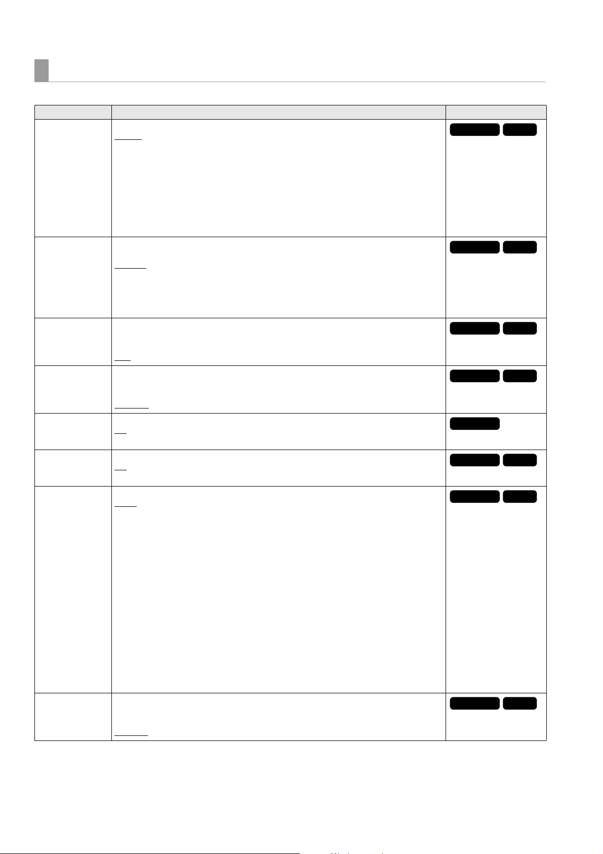
VIDEO
59.94Hz
50Hz
59.94Hz
50Hz
59.94Hz
50Hz
59.94Hz
50Hz
59.94Hz
59.94Hz
50Hz
59.94Hz
50Hz
59.94Hz
50Hz
_ is the factory default setting.
Item Settings and brief function description FREQ indications
Selects the video input signal.
: Selects the SDI connector (HD signal input).
HD SDI
SD-SDI: Selects the SDI connector (SD signal input).
INT SG:
INPUT SEL
INT SG
SG MOVE
WIDE SEL
SETUP(7.5%)
EDH(SD)
OUTPUT FORMAT
3G-SDI OUT
1
*
This menu is only for the AJ-PD500P
Selects the internal signal generator. The signal switches to the internal signal selected in
the INT SG menu item.
Note:
• When “SD SDI” is selected for the signal format of the “LINE&FREQ” setting, the signal
is up converted automatically to HD and recorded.
• When 1080P is up converted from an SD signal, the video will not be converted properly.
Sets the internal signal type. SMPTE and ARIB signals are enabled only when the
“LINE&FREQ” setting is set to the HD format (black in SD mode).
100%CB
75%CB: 75 % color bar
SMPTE: SMPTE color bar
ARIB: ARIB color bar
BLACK: Black
Switches to the function for displaying a square that automatically changes its position on
the INT SG.
ON: Displays.
OFF
Sets whether to record the WIDE information when “LINE&FREQ” is set to “480-59.94i” or
“576-50i.”
WIDE: Records the information.
NORMAL
Switches the setup. (When 480-59.94i only)
1
*
ON: Switches to the 7.5 % setup.
OFF: Turns off the 7.5 % setup.
Selects whether to superimpose EDH on SD SDI output signals.
ON
OFF: Does not superimpose EDH.
Selects the video signal output from the video output connector.
AUTO
Switches output automatically in accordance with the current recording and playback format.
• When 59.94 Hz is set
• When 50 Hz is set
: 100 % color bar
: Does not display.
: Does not record the information.
: Superimposes EDH.
:
1080p: 1080/59.94p
1080i: 1080/59.94i
480i: 480/59.94i
1080p: 1080/50p
1080i: 1080/50i
576i: 576/50i
Note:
• When other than “AUTO” is selected, a signal that differs from the recording and playback format is automatically converted before output.
• When 1080P is up converted from an SD signal, the video will not be converted properly.
• When an SD signal is output, the 480/59.94p or 576/50p signal is output from the HDMI
output connector.
Selects the 3G-SDI output format for when “LINE&FREQ” (➝ page 105) is “1080-59.94P” or
“1080-50P.”
LEVEL-A: Selects the 3G-SDI LEVEL-A format.
LEVEL-B
: Selects the 3G-SDI LEVEL-B DL format.
92
Setup Menu: Menu List
Page 93

Setup Menu
59.94Hz
50Hz
59.94Hz
50Hz
59.94Hz
50Hz
Item Settings and brief function description FREQ indications
Selects the aspect ratio for down-conversion output.
FIT-V
:
Changes the ratio to match the input size to the output size along the vertical axis. (The aspect ratio is maintained.)
DOWNCON MODE
UPCON MODE
GAMMA SELECT
FIT-H:
Changes the ratio to match the input size to the output size along the horizontal axis. (The
aspect ratio is maintained.)
FIT-HV:
Changes the ratio to match the input size to the output size along the horizontal and vertical
axes. (The aspect ratio may be distorted.)
Selects the angle of view for up-conversion recording.
FIT-V
:
Changes the ratio to match the input size to the output size along the vertical axis. (The aspect ratio is maintained.)
FIT-H:
Changes the ratio to match the input size to the output size along the horizontal axis. (The
aspect ratio is maintained.)
FIT-HV:
Changes the ratio to match the input size to the output size along the horizontal and vertical
axes. (The aspect ratio may be distorted.)
Selects gamma correction.
GAMMA1:
Corrects video shot by Varicam or in the FILM REC mode on an AJ-HPX3100 to film-quality
video.
(Equivalent to Telecine 5 of HD Gamma Corrector on the AJ-GBX27G)
GAMMA 2:
Corrects video shot by Varicam or in the FILM REC mode on an AJ-HPX3100 to film-quality
video.
(Equivalent to Telecine 6 of HD Gamma Corrector on the AJ-GBX27G)
GAMMA 3:
Converts video shot by Varicam or in the FILM REC mode on an AJ-HPX3100 by applying a
Cineon curve to produce video appropriate for film recording.
OFF
:
Does not correct the gamma.
Note:
• This setting is enabled during playback.
• If other than “OFF” is selected, the gamma correction value (GM½) will always be displayed on the OSD.
• Turning the power of the unit off also returns this GAMMA setting to “OFF.”
Setup Menu: Menu List
93
Page 94

AUDIO
59.94Hz
50Hz
59.94Hz
50Hz
59.94Hz
50Hz
59.94Hz
50Hz
59.94Hz
50Hz
59.94Hz
50Hz
59.94Hz
50Hz
59.94Hz
50Hz
59.94Hz
50Hz
_ is the factory default setting.
Item Settings and brief function description FREQ indications
Selects the audio input signal.
SDI
: Selects the SDI connector.
INPUT SEL
INPUT CH1 LEVEL
INPUT CH2 LEVEL
RATE CONV.
OUTPUT CH1/L
LEVEL
OUTPUT CH2/R
LEVEL
OUTPUT
EMBD(SD) CH
OUTPUT
EMBD(HD) CH
OUTPUT AES/EBU
CH
ANALOG: Selects the ANALOG AUDIO IN connector.
AES/EBU: Selects the AES/EBU connector.
INT SG: Selects the internal signal generator.
Selects the level for the CH1 analog audio input.
4 dB
0 dB
-3 dB
-20 dB
Selects the level for the CH2 analog audio input.
4 dB
0 dB
-3 dB
-20 dB
Records and plays without passing the video through the rate converter (without applying a
digital filter) during digital audio input/output.
: Records and plays while passing the data through the rate converter.
ON
OFF: Records and plays without passing the data through the rate converter.
Note:
• The on/off of all recording and playback channels is controlled simultaneously. It cannot
be set for each channel separately.
• When the rate converter is off, the video input and digital audio input need to be synchronized. The video input and the reference signal selected in “OUTPUT REF” (➝ page
106) also need to be synchronized. (If they are not synchronized, noise may be output.)
Selects the level for the CH1/L analog audio output.
4 dB
0 dB
-3 dB
-20 dB
Selects the level for the CH2/R analog audio output.
4 dB
0 dB
-3 dB
-20 dB
Selects the channels to multiplex on the SD SDI output.
OFF: Does not superimpose.
: Outputs the four channels CH1-4.
CH1-4
CH5-8: Outputs the four channels CH5-8.
CH1-8: Outputs the eight channels CH1-8.
Note:
• The four channels CH1-4 are always multiplexed during DV, DVCPRO, and DVCPRO50
playback.
• Some devices may not be able to receive eight channels. Check the specifications of
the receiving device before setting CH1-8.
Selects the channels to multiplex on the HD SDI output.
OFF: Does not superimpose.
: Outputs the eight channels CH1-8.
CH1-8
Note:
Channels not included in a playback clip are output as no sound.
Sets the channels to output to AES/EBU.
CH1-4
: Outputs the four channels CH1-4.
CH5-8: Outputs the four channels CH5-8.
Note:
Channels not included in a playback clip are output as no sound.
94
Setup Menu: Menu List
Page 95

Setup Menu
59.94Hz
50Hz
59.94Hz
50Hz
59.94Hz
50Hz
59.94Hz
50Hz
59.94Hz
50Hz
59.94Hz
50Hz
59.94Hz
50Hz
59.94Hz
50Hz
59.94Hz
50Hz
59.94Hz
50Hz
59.94Hz
50Hz
59.94Hz
50Hz
Item Settings and brief function description FREQ indications
Sets the channels to output to ANALOG AUDIO.
OUTPUT ANALOG
CH
MONITOR
CH1-2: Outputs the two channels CH1-2.
CH3-4: Outputs the two channels CH3-4.
CH5-6: Outputs the two channels CH5-6.
CH7-8: Outputs the two channels CH7-8.
: Outputs the signal selected in “MONITOR CH”.
Note:
Channels not included in a playback clip are output as no sound.
Sets the audio to output to the monitor outputs. Select the outputs for L and R. HDMI output
audio is also in accordance with this setting.
: Outputs CH1 to L and CH2 to R.
CH1 / 2
CH3 / 4: Outputs CH3 to L and CH4 to R.
MONITOR CH
MONITOR OUT
VOL.
SPEAKER OUT
LEVEL METER
REF LEVEL
1
*
This is the factory default setting of the AJ-PD500P.
2
*
This is the factory default setting of the AJ-PD500E.
CH1 + 2 / 3 + 4: Outputs CH1+2 to L and CH3+4 to R.
CH1 + 3 / 2 + 4: Outputs CH1+3 to L and CH2+4 to R.
CH5 / 6: Outputs CH5 to L and CH6 to R.
CH7 / 8: Outputs CH7 to L and CH8 to R.
CH5 + 6 / 7 + 8: Outputs CH5+6 to L and CH7+8 to R.
CH5 + 7 / 6 + 8: Outputs CH5+7 to L and CH6+8 to R.
Selects whether to link the volume of the audio monitor output from the MON L/R output connectors to the monitor volume adjustment knob.
UNITY:
Outputs the audio monitor output at a fixed level regardless of the position of the monitor volume adjustment knob.
VARIABLE
Links the volume of the audio monitor output to the monitor audio adjustment knob.
Turns on/off speaker output.
ON
OFF: Does not output from the speakers. (BEEP sounds are also not output.)
Switches the channels to indicate on the audio level meter.
CH1-4
CH5-8: Outputs the four channels CH5-8.
CH1-8: Outputs the eight channels CH1-8.
Selects the standard level.
FS-20
FS-18
FS-12: -12 dB
:
: Outputs from the speakers.
: Outputs the four channels CH1-4.
1
*
: -20 dB
2
*
: -18 dB
LAN
_ is the factory default setting.
Item Settings and brief function description FREQ indications
NETWORK SEL Selects network connection method.
LAN: Connects via the LAN connector on the unit.
: Does not use the network.
OFF
CLIENT SERVICE
FTP SERVER
URL
LOGIN USER
LOGIN PASSWORD
SSH Set this for transferring files using SSH.
LAN PROPERTY
MAC ADDRESS Displays the MAC address of the LAN connector of the unit.
Sets the name or address of the connection destination server.
Sets the user ID for the connection.
Sets the password for the connection.
ENABLE: Uses SSH.
DISABLE
: Does not use SSH.
Setup Menu: Menu List
95
Page 96

Item Settings and brief function description FREQ indications
59.94Hz
50Hz
59.94Hz
50Hz
59.94Hz
50Hz
59.94Hz
50Hz
59.94Hz
50Hz
59.94Hz
50Hz
59.94Hz
50Hz
59.94Hz
50Hz
59.94Hz
50Hz
DHCP Automatically sets the network settings by DHCP.
ENABLE: Uses DHCP (automatic assignment)
DISABLE
When “DISABLE” is selected, the following menu items are displayed. Set the items.
IP ADDRESS: Sets the IP address.
SUBNET MASK: Sets the subnet mask.
DEFAULT GATEWAY: Sets the default gateway address.
PRIMARY DNS: Sets the address of the primary DNS server.
SECONDARY DNS: Sets the address of the secondary DNS server.
NETWORK TOOLS
LOG DISPLAY Displays the connection log.
: Enter the settings without using DHCP (automatic assignment).
STATUS
DISPLAY
INITIALIZE Initializes various network settings to restore them to the factory defaults.
PING Checks the network connection.
Displays the network status.
DISPLAY
_ is the factory default setting.
Item Settings and brief function description FREQ indications
Sets whether to output the thumbnail screen, menu screen, and other screen display to
MONITOR OUT (SDI MON connector, HDMI connector, VIDEO OUT connector) or SDI OUT
OSD OUTPUT
OSD GRADE
OSD TC SELECT
WFM TYPE
(SDI OUT 1 to 2 connectors).
LCD: Does not output (displayed only on the LCD monitor).
LCD&MONITOR
ALL: Outputs to all of the LCD, MONITOR OUT, and SDI OUT.
Sets superimposed display for the recording or playback screen.
ALL
: Displays all.
NO LEVEL METER: Does not display the audio level meter.
Sets the superimposed display items.
Here, data indicates the CTL/TC/UB value selected with the [COUNTER] button.
TIME: Data
T&STATUS
T&S&M: Data, operating status, clip number, video format, audio bit rate
T&REC TIME: Data and REC TIME
T&REC DATE: Data and REC DATE
T&UB: Data and user bits
However, when UB is selected with the [COUNTER] button, the time code is indicated
after the user bits.
T&CTL: Data and CTL
However, when CTL is selected with the [COUNTER] button, the time code is indicated
after the CTL data.
T&T: Data and time code
: Outputs to MONITOR OUT.
: Data and operating status
Note:
• When “T&S&M” is set, an error message appears in the superimposed display if a warning or error occurs.
Selects waveform and vector monitor display.
WAVE: Waveform display
VECTOR: Vector display
OFF
: Does not display.
96
Setup Menu: Menu List
Page 97

Setup Menu
59.94Hz
50Hz
59.94Hz
50Hz
59.94Hz
50Hz
59.94Hz
50Hz
59.94Hz
50Hz
59.94Hz
50Hz
59.94Hz
50Hz
59.94Hz
50Hz
59.94Hz
50Hz
59.94Hz
50Hz
Item Settings and brief function description FREQ indications
Selects the display position for the waveform monitor.
WFM POSI
RIGHT/TOP
LEFT/TOP: Positioned at top left.
RIGHT/BOTTOM: Positioned at bottom right.
LEFT/BOTTOM: Positioned at bottom left.
: Positioned at top right.
Note:
The display on the LCD monitor moves left or right only.
Sets whether to display the 4:3 marker on the LCD monitor.
4:3 MARKER
ON: Displays.
: Does not display.
OFF
LCD MONITOR
_ is the factory default setting.
Item Settings and brief function description FREQ indications
Turns off the backlight of the LCD monitor automatically if a set time (approximately 5 min-
TIME OUT
BACKLIGHT
BRIGHTNESS
COLOR LEVEL
CONTRAST
R CONTRAST
G CONTRAST
B CONTRAST
utes) elapses after any operation is performed.
5min: Turns off the backlight of the LCD monitor automatically after approximately 5 minutes.
OFF
: Does not turn off the backlight of the LCD monitor.
Adjusts the brightness of the LCD monitor backlight.
-3: Darkest
l
0
: Normal brightness
1: Brighter than normal
Adjusts the brightness of the LCD monitor.
-15 to 0
Adjusts the color level of the LCD monitor.
-15 to 0
Adjusts contrast of the LCD monitor.
-30 to 0
to 15
to 15
to 30
Note:
This value multiplied by the R, G, and B contrast setting becomes the contrast adjustment
value for R, G, and B.
Adjusts the R (Red) contrast of the LCD monitor.
-30 to 0
to 30
Note:
This setting multiplied by the “CONTRAST” setting becomes the contrast setting.
Adjusts the G (Green) contrast of the LCD monitor.
-30 to 0
to 30
Note:
This setting multiplied by the “CONTRAST” setting becomes the contrast setting.
Adjusts the B (Blue) contrast of the LCD monitor.
-30 to 0
to 30
Note:
This setting multiplied by the “CONTRAST” setting becomes the contrast setting.
Setup Menu: Menu List
97
Page 98

EXT DC IN
59.94Hz
50Hz
59.94Hz
50Hz
59.94Hz
50Hz
59.94Hz
50Hz
59.94Hz
50Hz
_ is the factory default setting.
Item Settings and brief function description FREQ indications
Sets the remaining level detection type for when an external DC power supply or battery is
connected to the DC IN connector. Set NEAR END and END of TYPE A and TYPE B to match
EXT DC IN
SELECT
TYPE A NEAR END
TYPE A END
TYPE B NEAR END
TYPE B END
the battery that is to be used.
DC PWR SUPPLY
TYPE A
TYPE B
Sets the voltage (in 0.1 V steps) at which to display warning information when the voltage
drops for the battery to be used as “TYPE-A” selected in the “EXT DC IN SELECT” menu
item.
10.6 V to 12.9 V
to 15.0 V
Note:
A voltage that will be lower than END cannot be set.
Sets the voltage (in 0.1 V steps) at which to automatically turn off the power of the unit when
the voltage drops for the battery to be used as “TYPE-A” selected in the “EXT DC IN SELECT” menu item.
10.6 V to 12.4 V
to 15.0 V
Note:
A voltage that will be higher than NEAR cannot be set.
Sets the voltage (in 0.1 V steps) at which to display warning information when the voltage
drops for the battery to be used as “TYPE-B” selected in the “EXT DC IN SELECT” menu
item.
10.6 V to 12.9 V
to 15.0 V
Note:
A voltage that will be lower than END cannot be set.
Sets the voltage (in 0.1 V steps) at which to automatically turn off the power of the unit when
the voltage drops for the battery to be used as “TYPE-B” selected in the “EXT DC IN SELECT” menu item.
10.6 V to 12.4 V
to 15.0 V
Note:
A voltage that will be higher than NEAR cannot be set.
98
Setup Menu: Menu List
Page 99

Setup Menu
59.94Hz
50Hz
USER BUTTON
You can assign specific functions set in menus to the [USER1] to [USER6] buttons.
The settings are stored internally and retained even when the unit is turned off and on. The assigned functions and settings can
be confirmed in the DIAG display.
_ is the factory default setting.
Item Settings and brief function description FREQ indications
TEXT MEMO: Functions as the text memo button.
MARKER: Functions as the shot marker ON/OFF button.
DELETE: Functions as the “DELETE” shortcut button.
FORMAT: Functions as the “FORMAT” shortcut button.
COPY: Functions as the “COPY” shortcut button.
EXPORT: Functions as the “EXPORT” shortcut button.
USER1
USER2
USER3
USER4
USER5
USER6
CLIP PROPERTY
CARD STATUS: Functions as the “CARD STATUS” shortcut button.
ONE CLIP PLAY: Functions as the “ONE CLIP PLAY” button.
SLOT CLIPS:
Switches the thumbnail screen display between “SELECTED CLIPS” ➝ “SLOT1” ➝ “SLOT2” ➝.
SLOT SEL: Changes the P2 card slot for recording.
REC MEDIA: Changes the “REC/PB SETUP” - “REC MEDIA” settings.
DATA DISPLAY: Changes the “DATA DISPLAY” settings.
STOP EE SEL: Changes the “STOP EE SEL” settings.
OUTPUT REF: Changes the “OUTPUT REF” settings.
SEEK POS SEL: Changes the “SEEK POS SEL” settings.
CTL DISPLAY: Changes the “CTL DISPLAY” settings.
TCG MODE: Changes the “TCG MODE” settings.
UBG MODE: Changes the “UBG MODE” settings.
RUN MODE: Changes the “RUN MODE” settings.
EXT TC SEL: Changes the “EXT TC SEL” settings.
VIDEO IN SEL:Changes the “INPUT SEL” (VIDEO) settings.
INT SG: “VIDEO” - Changes the “INT SG” settings.
AUDIO IN SEL: Changes the “INPUT SEL” (AUDIO) settings.
MONITOR CH: Changes the “MONITOR CH” settings.
LEVEL METER: Changes the “LEVEL METER” settings.
OSD OUTPUT: Changes the “OSD OUTPUT” settings.
OSD GRADE: Changes the “OSD GRADE” settings.
WFM TYPE: Changes the “WFM TYPE” settings.
Note:
• The same item can be assigned to other [USER] buttons.
The settings are the same as “USER1”.
The factory default setting is MONITOR CH
The settings are the same as “USER1”.
The factory default setting is TEXT MEMO
The settings are the same as “USER1”.
The factory default setting is REC MEDIA
The settings are the same as “USER1”.
The factory default setting is LEVEL METER
The settings are the same as “USER1”.
The factory default setting is MARKER
: Functions as the “CLIP PROPERTY” shortcut button.
.
.
.
.
.
Setup Menu: Menu List
99
Page 100

PARALLEL PORT
59.94Hz
50Hz
Registers functions to the input connectors and registers statuses to the output connectors of the PARALLEL REMOTE connector.
_ is the factory default setting.
Item Settings and brief function description FREQ indications
REC BUTTON: Performs the same operation as the [REC] button.
REC+PLAY BUTTON:
Performs the same operation as simultaneously pressing the [REC] and [PLAY] buttons.
PLAY BUTTON: Performs the same operation as the [PLAY] button.
STILL/PAUSE BUTTON: Performs the same operation as the [PAUSE] button.
FF BUTTON: Performs the same operation as the [FF] button.
STOP BUTTON: Performs the same operation as the [STOP] button.
REW BUTTON: Performs the same operation as the [REW] button.
SHTL BUTTON: Performs the same operation as the [SEARCH] button.
AUDIO LVL REC BUTTON: Performs the same operation as the [AUDIO LEVEL-REC] button.
AUDIO LVL PB BUTTON: Performs the same operation as the [AUDIO LEVEL-PB] button.
REMOTE BUTTON: Performs the same operation as the [REMOTE] button.
COUNTER BUTTON: Performs the same operation as the [COUNTER] button.
RESET BUTTON: Performs the same operation as the [RESET] button.
PRESET BUTTON: Performs the same operation as the [TC PRESET] button.
DISPLAY BUTTON: Performs the same operation as the [DISPLAY] button.
USER1 BUTTON: Performs the same operation as the [USER1] button.
USER2 BUTTON: Performs the same operation as the [USER2] button.
USER3 BUTTON: Performs the same operation as the [USER3] button.
USER4 BUTTON: Performs the same operation as the [USER4] button.
USER5 BUTTON: Performs the same operation as the [USER5] button.
USER6 BUTTON: Performs the same operation as the [USER6] button.
UP BUTTON: Performs the same operation as the up cursor button.
DOWN BUTTON: Performs the same operation as the down cursor button.
PORT1
PORT2 The settings are the same as PORT1. The factory default setting is STOP BUTTON.
PORT3 The settings are the same as PORT1. The factory default setting is FF BUTTON.
PORT4 The settings are the same as PORT1. The factory default setting is REW BUTTON.
PORT5 The settings are the same as PORT1. The factory default setting is REC BUTTON.
PORT6 The settings are the same as PORT1. The factory default setting is SHTL BUTTON.
PORT7 The settings are the same as PORT1. The factory default setting is USER1 BUTTON.
LEFT BUTTON: Performs the same operation as the left cursor button.
RIGHT BUTTON: Performs the same operation as the right cursor button.
SET BUTTON: Performs the same operation as the [SET] button.
THUMBNAIL BUTTON: Performs the same operation as the [THUMBNAIL] button.
SHIFT BUTTON: Performs the same operation as the [SHIFT] button.
MENU BUTTON: Performs the same operation as the [MENU] button.
EXIT BUTTON: Performs the same operation as the [EXIT] button.
KEY INHIBIT: Prohibits/allows operation of the front panel.
TEXT MEMO: Adds a text memo.
MARKER: Adds a shot mark.
ONE CLIP PLAY: Functions as the ONE CLIP PLAY button.
SLOT CLIPS:
Switches the thumbnail screen display between “SELECTED CLIPS” > “SLOT1” > “SLOT2” >.
SLOT SEL: Changes the P2 card slot for recording.
REC MEDIA: “REC/PB SETUP” - Changes the “REC MEDIA” settings.
TCG MODE: Changes the “TCG MODE” settings.
UBG MODE: Changes the “UBG MODE” settings.
RUN MODE: Changes the “RUN MODE” settings.
EXT TC SEL: Changes the “EXT TC SEL” settings.
VIDEO IN SEL:Changes the “INPUT SEL” (VIDEO) settings.
INT SG: “VIDEO” - Changes the “INT SG” settings.
AUDIO IN SEL: Changes the “INPUT SEL” (AUDIO) settings.
MONITOR CH SEL: Changes the “MONITOR CH SEL” settings.
LEVEL METER: Changes the “LEVEL METER” settings.
WFM TYPE: Changes the “WFM TYPE” settings.
100
Setup Menu: Menu List
 Loading...