

Page 1
BARS
COUNT
ER
RE
S
ET
ZEBR
A
This product is eligible for the AVCCAM
3 Year Warranty Repair Program. For
details, see page 5.
Before use
Operating Instructions
Memory Card Camera-Recorder
of parts
Model No. AG-HMC41E
Before operating this product, please read the instructions carefully and save this manual
for future use.
ENGLISH
F0709U0 -P
VQT2H31 (E)
Reference Menu Displays Editing Playback Shooting Preparation Description
Page 2
Read this first!
indicates safety information.
WARNING:
TO REDUCE THE RISK OF FIRE OR
•
SHOCK HAZARD, DO NOT EXPOSE THIS
EQUIPMENT TO RAIN OR MOISTURE.
TO REDUCE THE RISK OF FIRE OR
•
SHOCK HAZARD, KEEP THIS EQUIPMENT
AWAY FROM ALL LIQUIDS. USE AND
STORE ONLY IN LOCATIONS WHICH
ARE NOT EXPOSED TO THE RISK OF
DRIPPING OR SPLASHING LIQUIDS, AND
DO NOT PLACE ANY LIQUID CONTAINERS
ON TOP OF THE EQUIPMENT.
WARNING:
Always keep memory cards (optional
accessory) or accessories (coin battery, PINBNC conversion plugs, ferrite cores, cable
ties, XLR connector cap) out of the reach of
babies and small children.
CAUTION:
Do not remove panel covers by unscrewing
them.
To reduce the risk of electric shock, do not
remove the covers. No user serviceable parts
inside.
Refer servicing to qualified service personnel.
CAUTION:
TO REDUCE THE RISK OF FIRE OR SHOCK
HAZARD AND ANNOYING INTERFERENCE,
USE THE RECOMMENDED ACCESSORIES
ONLY.
CAUTION:
In order to maintain adequate ventilation, do
not install or place this unit in a bookcase,
built-in cabinet or any other confined space. To
prevent risk of electric shock or fire hazard due
to overheating, ensure that curtains and any
other materials do not obstruct the ventilation.
CAUTION:
Do not lift the unit by its handle while the
tripod is attached. When the tripod is attached,
its weight will also affect the unit’s handle,
possibly causing the handle to break and
hurting the user. To carry the unit while the
tripod is attached, take hold of the tripod.
CAUTION:
Danger of explosion or fire if battery is mistreated.
•
Do not leave the battery in an automobile
•
exposed to direct sunlight for a long period
of time with doors and windows closed.
Do not disassemble the battery or dispose
•
of it in fire.
Do not store in temperatures over 60°C (140°F).
•
For Battery Pack
Use specified charger.
•
Replace only with same or specified type.
•
For Battery of Remote Controller
Replace battery with part No. CR2025 only.
•
Do not recharge the battery.
•
CAUTION:
THE MAINS PLUG OF THE POWER SUPPLY
CORD SHALL REMAIN READILY OPERABLE.
THE AC RECEPTACLE (MAINS SOCKET
OUTLET) SHALL BE INSTALLED NEAR
THE EQUIPMENT AND SHALL BE EASILY
ACCESSIBLE.
TO COMPLETELY DISCONNECT THIS
EQUIPMENT FROM THE AC MAINS,
DISCONNECT THE POWER CORD PLUG
FROM THE AC RECEPTACLE.
CAUTION:
Do not jar, swing, or shake the unit by its
handle while the conversion lens or another
accessory is attached.
Due to the added weight of the conversion
lens, any strong jolt to the handle may
damage the unit or result in personal injury.
CAUTION:
EXCESSIVE SOUND PRESSURE FROM
EARPHONES AND HEADPHONES CAN
CAUSE HEARING LOSS.
CAUTION:
Do not leave the unit in direct contact with the
skin for long periods of time when in use.
Low temperature burn injuries may be suffered
if the high temperature parts of this unit are
in direct contact with the skin for long periods
of time.
When using the equipment for long periods of
time, make use of the tripod.
Note:
Camera-Recorder
The rating plate is on the underside of the camerarecorder.
AC Adapter
The rating plate is on the underside of the AC Adapter.
Disconnect the AC mains plug from the AC mains socket when not in use.
2
Page 3
indicates safety information.
Caution for AC Mains Lead
FOR YOUR SAFETY PLEASE READ THE FOLLOWING TEXT CAREFULLY.
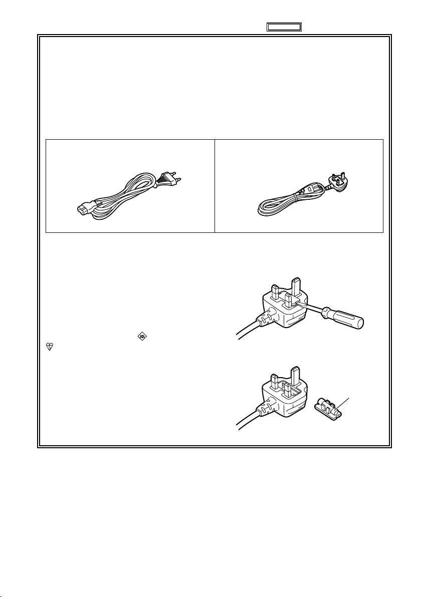
This product is equipped with 2 types of AC mains cable. One is for continental Europe, etc.
and the other one is only for U.K.
Appropriate mains cable must be used in each local area, since the other type of mains cable is
not suitable.
FOR CONTINENTAL EUROPE, ETC.
Not to be used in the U.K.
FOR U.K. ONLY
This appliance is supplied with a moulded
three pin mains plug for your safety and
convenience.
A 5 amp fuse is fitted in this plug.
Should the fuse need to be replaced please
ensure that the replacement fuse has a rating
of 5 amps and that it is approved by ASTA or
BSI to BS1362.
Check for the ASTA mark or the BSI mark
on the body of the fuse.
If the plug contains a removable fuse cover
you must ensure that it is refitted when the
fuse is replaced.
If you lose the fuse cover the plug must
not be used until a replacement cover is
obtained.
A replacement fuse cover can be purchased
from your local Panasonic Dealer.
FOR U.K. ONLY
How to replace the fuse
1. Open the fuse compartment with a
screwdriver.
2. Replace the fuse
Fuse
3
Page 4

EMC NOTICE FOR THE PURCHASER/USER OF THE APPARATUS
1. Applicable standards and operating environment
The apparatus is compliant with:
�
standards EN55103-1 and EN55103-2 1996.11, and
�
electromagnetic environments E1, E2, E3 and E4.
2. Pre-requisite conditions to achieving compliance with the above standards
<1> Peripheral equipment to be connected to the apparatus and special connecting cables
The purchaser/user is urged to use only equipment which has been recommended by us as
�
peripheral equipment to be connected to the apparatus.
The purchaser/user is urged to use only the connecting cables described below.
�
For the connecting cables, use shielded cables which suit the intended purpose of the apparatus.
<2>
Video signal connecting cables
�
Use double shielded coaxial cables, which are designed for 75-ohm type high-frequency
applications, for SDI (Serial Digital Interface).
Coaxial cables, which are designed for 75-ohm type high-frequency applications, are
recommended for analog video signals.
Audio signal connecting cables
�
If your apparatus supports AES/EBU serial digital audio signals, use cables designed for AES/EBU.
Use shielded cables, which provide quality performance for high-frequency transmission
applications, for analog audio signals.
Other connecting cables (IEEE1394, USB)
�
Use shielded cables, which provide quality performance for high-frequency applications, as
connecting cables.
When connecting to the DVI signal terminal, use a cable with a ferrite core.
�
If your apparatus is supplied with ferrite core(s), they must be attached on cable(s) following
�
instructions in this manual.
3. Performance level
The performance level of the apparatus is equivalent to or better than the performance level required
by these standards.
However, the apparatus may be adversely affected by interference if it is being used in an EMC
environment, such as an area where strong electromagnetic fields are generated (by the presence
of signal transmission towers, cellular phones, etc.). In order to minimize the adverse effects of the
interference on the apparatus in cases like this, it is recommended that the following steps be taken
with the apparatus being affected and with its operating environment:
1. Place the apparatus at a distance from the source of the interference.
2. Change the direction of the apparatus.
3. Change the connection method used for the apparatus.
4.
Connect the apparatus to another power outlet where the power is not shared by any other appliances.
Recommendation for Use of Genuine Panasonic Battery
(Rechargeable Battery)
Thank you for using a Panasonic product.
It has been found that counterfeit battery packs which look very similar to the genuine product are
made available to purchase in some markets. Some of these battery packs are not adequately
protected with internal protection to meet the requirements of appropriate safety standards. There is
a possibility that these battery packs may lead to fire or explosion. Please be advised that we are not
liable for any accident or failure occurring as a result of use of a counterfeit battery pack. To ensure that
safe products are used we would recommend that a genuine Panasonic battery pack is used.
Be aware that many batteries sold at extremely cheap prices or in situations where it is difficult to
•
verify the actual products before purchase have proven to be counterfeit.
Batteries that may be used with this product
■
(Correct as of August 2009)
Panasonic VW-VBG130, VW-VBG260 and VW-VBG6 batteries may be used with this product.
The VW-VBG130,VW-VBG260 and VW-VBG6 batteries contain a function to enable verification as to
whether they may be safely used with this product.
4
Page 5
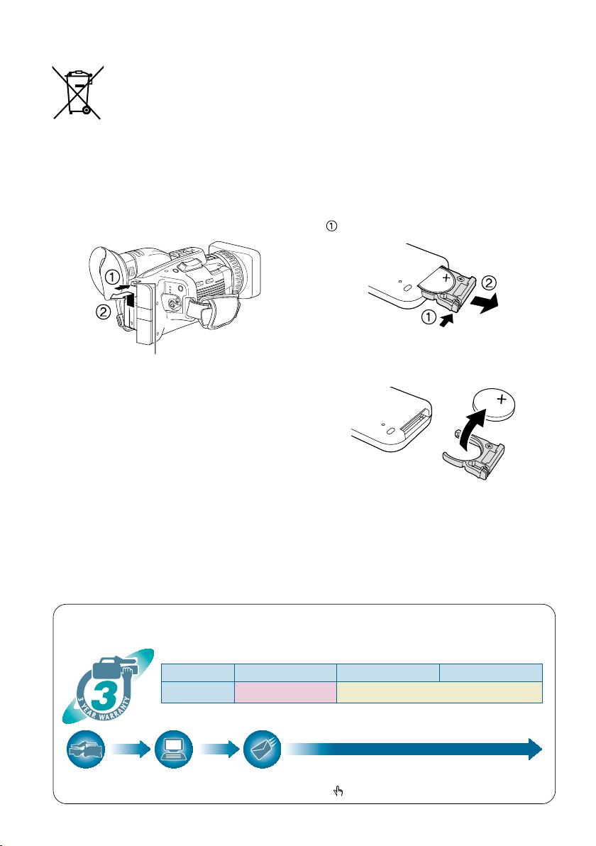
To remove the battery
2$
219'
4
37+%-56#46
2*161
%#/'4
#
*1: Please note that this extended warranty is not available in some countries/regions. *2: Not all models eligible for extended warranty coverage.
*3: The basic warranty period may vary depending on the country/region. *4: Not all repair work is covered by this extended warranty.
Purchase
AVCCAM product
Register online
within 1 month
“Registration Notice”
e-mail sent
Details about user registration and the extended warranty: http://panasonic.biz/sav/pass_e
Free 3 years of Warranty Repairs
Customers who register as users on the website will receive an extended warranty repair valid for up to
three years.
AVCCAM 3 Year Warranty Repair Program*
1
Thank you for purchasing this Panasonic AVCCAM device.
Register as a user for this device to receive a special service warranty up to three years of free warrant y repai rs.
Make sure to save the “Registration Notice” e-mail
during the warranty period.
1st year 2nd year 3rd year
AVCCAM device
*
2
Basic warranty
*
3
Extended warranty repair
*
4
EU
Main Power Battery
Remote Control Battery
(Refer to page 23 for the detail.)
1) Push the catch in the direction shown by arrow
Press the battery release button.
Battery release button
2) Remove the button-type battery from the battery
holder.
Back-up Battery
For the removal of the battery for disposal at the
•
end of its service life, please consult your dealer.
EEE Yönetmeliğine Uygundur.
EEE Complies with Directive of Turkey.
to remove the holder.
5
Page 6

The SDHC logo is a trademark.
●
The miniSD logo is a trademark.
●
“AVCHD” and the “AVCHD” logo are trademarks of Panasonic Corporation and Sony Corporation.
●
This product has been manufactured under license from Dolby Laboratories.
●
Dolby and the double-D symbol are trademarks of Dolby Laboratories.
HDMI, the HDMI logo, and High-Definition Multimedia Interface are trademarks or registered trademarks
●
of HDMI Licensing LLC.
LEICA is a registered trademark of Leica Microsystems IR GmbH.
●
DICOMAR is a registered trademark of Leica Camera AG.
●
Microsoft®, Windows®, and Windows Vista® are either registered trademarks or trademarks of Microsoft
●
Corporation in the United States and/or other countries.
Screenshots are used in accordance with Microsoft Corporation guidelines.
●
IBM and PC/AT are registered trademarks of International Business Machines Corporation.
●
Intel® is a registered trademark or a trademark of Intel Corporation in the United States and/or other
●
countries.
Macintosh® is a trademark of Apple Inc., registered in the United States and other countries.
●
Other model names, company names, and product names listed in these operating instructions are
●
trademarks or registered trademarks of their respective companies.
This product is licensed under the AVC Patent Portfolio License for the personal and non-commercial
●
use of a consumer, and no license is granted or shall be implied for any use other than the personal
uses detailed below.
– To encode video in compliance with the AVC standard (“AVC Video”)
– To decode AVC Video that was encoded by a consumer engaged in a personal and non-commercial activity
– To decode AVC Video that was obtained from a video provider licensed to provide AVC Video
• Additional information may be obtained from MPEG LA, LLC (http://www.mpegla.com).
– Separate license contracts must be obtained from MPEG LA where SD Memory Cards containing information
recorded with this product are to be distributed to end users for commercial purposes. “End user” refers to
persons or organizations handling such contents for personal use.
Note concerning illustrations in these instructions
Illustrations (camera-recorder, menu screens, etc.) in these operating instructions differ slightly from the
•
actual camera-recorder.
References
References are shown as (Page 00).
•
Terminology
Both SD Memory Cards and SDHC Memory Cards as referred to as “SD Memory Cards” in these
•
operating instructions.
Video that is created during a single recording operation is referred to as a “clip” in these operating
•
instructions.
6
Page 7
Contents
Read this first! ................................................2
Before use
Operating precautions ................................... 9
Precaution for use ........................................ 11
SD Memory Cards compatible with
this product .................................................. 12
(SD speed class 4)........................ 13
SDHC Memory Cards ...................................... 13
Compatibility of recorded video ....................... 14
About AVCHD .................................................. 14
Accessories ..................................................15
Optional accessories ...................................16
Using tele conversion lenses,
wide conversion lenses ............................... 16
Description of parts
Description of parts ......................................17
Right side and rear side .................................. 17
Left side ........................................................... 18
Terminals and mounting parts .........................19
Remote control ................................................ 20
Preparation
Recharging the battery ................................21
Recharging ...................................................... 21
Power sources .............................................. 23
Using the battery .............................................23
Using the AC adapter ...................................... 23
Adjusting the hand strap ............................. 24
Attaching the shoulder strap .......................24
Detaching and attaching the lens hood .....24
Attaching the handle .................................... 25
Fitting the eye cup ........................................ 25
The remote control ....................................... 26
Insert the battery ............................................. 26
Remote control usable range ..........................26
Turn on/off the camera .................................26
Quick Start mode .......................................... 27
Tally lamp ...................................................... 27
Touch panel ................................................... 28
Using the touch panel ...................................... 28
Viewfinder .....................................................29
Using the viewfinder ........................................ 29
Using the LCD ................................................. 30
Emphasizing outlines ...................................... 30
Adjusting the screen display ............................ 31
Adjusting the touch panel ................................ 31
Setting the calendar ..................................... 32
Setting the time zone ....................................... 32
Setting the clock .............................................. 32
Shooting
Basic shooting operations ..........................33
Preparing for recording .................................... 33
SD Memory Card ACCESS lamp .................... 33
Shooting in auto mode .................................... 34
Checking photos taken (REC CHECK) ...........35
Formatting SD Memory Cards ......................... 35
SD Memory Card recording times ................... 36
Removing SD Memory Card ........................... 37
Protecting SD Memory Cards .......................... 37
Repairing SD Memory Cards .......................... 37
Using the zoom function .............................. 38
Digital zoom function ....................................... 38
Shooting in progressive mode .................... 39
Shooting in manual mode ............................ 40
Switching to manual mode .............................40
Manual focusing .............................................40
Using focus assist ........................................... 41
Setting the aperture and gain .......................... 41
Adjusting the white balance and
black balance ..............................................42
Shooting techniques for different targets .. 44
Touch auto focus (CAMERA mode only) ......... 44
Self-portrait shooting ......................................44
Zebra pattern .................................................. 45
Marker .............................................................45
Checking and displaying shooting status ........45
PRE REC ........................................................ 46
Optical Image Stabilizer .................................. 46
Adding effects to images ................................. 46
Using the USER buttons ................................ 46
Backlight compensation .................................. 47
Color bars ........................................................ 47
Wave form monitor function ............................. 47
Adjusting the headphone volume
while shooting .............................................. 47
Shot mark function .......................................... 47
Interval recording ............................................. 48
Time stamp function ........................................ 49
LAST CLIP function ......................................... 49
Adjusting the shutter speed ........................ 50
Synchro scan ................................................... 52
Adjusting the mic input level ....................... 53
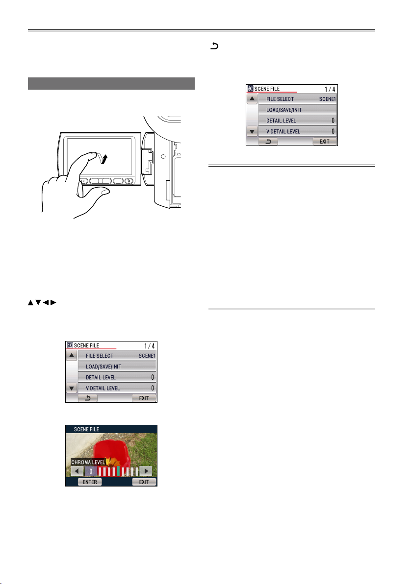
Using scene files .......................................... 54
Loading scene files .......................................... 54
Setting and saving scene files ......................... 54
Initializing scene files ....................................... 55
Clip metadata ................................................ 56
Loading the metadata ...................................... 57
Selecting the USER CLIP NAME recording
method ........................................................57
Using the Counter ........................................58
Counter display ............................................... 58
Charging the built-in battery/
Setting the time code ........................... 59
Recharging the built-in battery ........................ 59
Setting the time code ....................................... 59
7
Page 8

Contents (continued)
Specifying the time code ................................59
Setting user information .................................. 60
Shooting photos ........................................... 61
Setting the aspect ratio / recording pixels ....... 62
Setting the picture quality ................................ 62
Maximum number of photos ............................ 63
Playback
Thumbnail screen ......................................... 65
During clip playback ........................................65
During photo playback ..................................... 66
Thumbnail operations .................................. 67
Selecting the thumbnail display method .......... 67
Format card and card information ...................68
Confirming clip information .............................. 69
Adding a SHOT MARK to a clip....................... 69
Playing back clips ........................................70
Clip playback settings.................................. 73
Set playback format ......................................... 73
Repeat playback .............................................. 73
Resume playback (RESUME PLAY) ............... 73
Playing back photos..................................... 74
Playback by date ............................................. 75
Useful playback functions ........................... 76
Adjust volume (remote control) ....................... 76
Viewing images on a television .......................76
Checking the date and time ............................. 76
Deleting clips/photos
(videos and photos) .............................. 77
Deleting multiple clips or photos
simultaneously ............................................. 77
Selecting clips or photos to delete ................... 77
Setting protection (videos and photos) ...... 78
Protecting clips ................................................ 78
Protecting photos ............................................ 78
DPOF settings (photos) ...............................79
Printing photos on a printer (PictBridge) ... 80
Menu
Using the setup menus ................................ 95
Using the menus ............................................. 95
Using Quick Menu and Function Navi ............. 96
Initializing the menu settings ...........................97
Setup menu structure ..................................98
CAMERA mode menu ..................................... 98
PHOTO mode menu ........................................ 98
PB mode menu ................................................ 99
Setup menu list ........................................... 100
SCENE FILE screen ...................................... 100
CAMERA SETUP screen...............................101
RECORD SETUP screen .............................. 102
PICTURE screen ........................................... 104
PLAY SETUP screen ..................................... 105
OPERATION screen ...................................... 105
PHOTO SETUP screen ................................. 105
SW&DISP SETUP screen ............................. 106
OTHER FUNCTIONS screen ........................ 109
Reference
Before calling for service........................... 112
Updating the firmware ................................ 116
Cleaning ...................................................... 116
Storage Precautions................................... 117
Recording format ........................................ 118
How to handle data recorded on
SD Memory Card ................................. 119
Specifications ............................................. 120
Editing
Connecting external units ...........................82
Headphones .................................................... 82
External microphone (Stereo mini jack
compatible) .................................................. 82
External microphone (XLR Microphone
Adapter (optional) compatible) .................... 82
Computer (non-linear editing/file transfer) ....... 83
Video deck (Dubbing) ...................................... 83
TV/Monitor ....................................................... 84
Nonlinear editing .......................................... 85
Displays
Screen displays ............................................ 86
Regular displays .............................................. 86
Main warning displays ..................................... 91
Setting the DISPLAY items .............................. 93
8
Page 9

Operating precautions
Do not allow any water to get into the camerarecorder when using it in the rain or snow or at
the beach.
Failure to heed this caution will cause the
•
camera-recorder or a card to malfunction (and
may result in irreparable damage).
Keep the camera-recorder away from
equipment (such as TV sets and video game
machines) that generate magnetic fields.
Using the camera-recorder on top of or near a
•
TV set may cause distortion in the images and/or
sound due to the electromagnetic waves that the
set emits.
The powerful magnetic fields generated by
•
speakers or large motors may damage your
recordings or distort the images.
The electromagnetic waves emitted from a
•
microcomputer will adversely affect the camerarecorder, causing the images and/or sound to be
distorted.
If the camera-recorder is so adversely affected by
•
products that generate magnetic fields that it no
longer operates properly, turn it off and remove
the battery or unplug the AC adapter from the
power outlet. Then install the battery again or
reconnect the AC adapter. After this, turn the
camera-recorder back on.
Do not use the camera-recorder near radio
transmitters or high-voltage equipment.
Using the camera-recorder near a radio
•
transmitter or high-voltage equipment may
adversely affect the recorded images and/or
sound.
Do not allow any sand or dust to get into the
camera-recorder when using it at the beach
and other similar places.
Sand and dust can damage the camera-recorder
•
or a card. (Be especially careful when inserting or
removing a card.)
AC adapter and battery
If the CHARGE lamp continues to blink even
•
when the battery temperature is normal, there
may be something wrong with the battery or AC
adapter. Contact your dealer.
The battery takes longer to charge when it is
•
warm.
The AC adapter can interfere with radio reception
•
so keep radios at least 1 meter away from it.
The AC adapter may make some noise when you
•
are using it, but this is normal.
Take precautions not to drop the camera when
moving it.
Strong impacts may damage the camera and
•
cause it to stop working.
Handle the camera with care, using the hand
•
strap or shoulder strap to carry it.
Do not spray the camera with insect sprays or
other volatile substances.
These can warp the camera or cause the finish
•
to come off.
Do not leave the camera-recorder in contact with
•
rubber or PVC products for extended periods of
time.
After use, remove the battery and disconnect
the AC power supply cable.
Battery characteristics
This camera-recorder uses a rechargeable
lithiumion battery that uses its internal chemical
reaction to generate electrical energy. This reaction
is easily influenced by the ambient temperature
and humidity, and the battery’s effective operating
time is reduced as the temperature rises or falls. In
very low temperatures, the battery may last only 5
minutes.
Protective circuitry functions if you use the battery
where it is very hot and you will have to wait before
you can use it again.
Remove the battery after use.
Completely remove the battery. (The battery
continues to be used even if you have turned
the camera off.) The battery can over discharge
if you leave it in the camera and it may become
impossible to recharge it.
Disposing of spent batteries
The battery will become unchargeable. Rather than
throwing the battery into the garbage, take it to a
store that can assist in recycling it.
(Continued on the next page)
Before use
9
Page 10

Operating precautions (continued)
What to remember when throwing memory
cards away or transferring them to others
Formatting memory cards or deleting data using
the functions of the unit or a computer will merely
change the file management information: it will
not completely erase the data on the cards. When
throwing these cards away or transferring them
to others, either physically destroy them or use a
data deletion program for computers (commercially
available) to completely erase the data. Users are
responsible for managing the data on their memory
cards.
Liquid crystal displays
Images or letters can get burned onto the screen
•
of the LCD or viewfinder if they are displayed for
a long time, but you can fix this by leaving the
camera off for several hours.
The liquid crystal parts are highly precise with
•
99.99% of the pixels effective. This leaves less
than 0.01% of pixels that may not light or may
remain on all the time. These phenomena are
normal and will have no effect on the images you
shoot.
Condensation may form if you use the camera
•
where temperatures fluctuate. Wipe dry with a
soft, dry cloth.
The LCD may appear dim after immediately
•
turning on a cold camera, but will brighten as the
camera warms up.
Do not point the lens or viewfinder at the sun.
Doing so may damage the parts inside.
Protective caps for the connectors
Keep the protective caps fitted over any
connectors that are not being used.
10
Page 11
Precaution for use
Always take some trial shots before actual shooting.
When shooting important events (such as weddings), always take some trial shots and check that the
•
sound and images have been recorded properly before actual shooting.
Be sure to check and set the calendar and time zone.
These settings affect the control and playback sequence of the recorded contents. Before making a
•
recording, set and check the calendar and time zone. (Page 32)
Panasonic makes no guarantees for your recordings.
Please understand that Panasonic makes no guarantees for your recordings in cases where images and/
•
or sound were not recorded as you intended due to problems with the camera-recorder or SD/SDHC
Memory Cards.
Respect copyrights
Copyright laws forbid the use of video and audio material you have recorded for any purpose other than
•
your own personal enjoyment. Remember that restrictions apply to the shooting of certain material even
if it is intended for private use.
Media that can be used in this unit
SD/SDHC Memory Cards can be used in this unit. For details, refer to page 12.
•
Mounting the camera-recorder on a tripod
The tripod mounting hole is 5.5 mm deep. Do not force the tripod screw beyond this depth.
•
You can damage the camera-recorder if you use any screw other than 1/4-20UNC.
Before use
Attach the tripod to the tripod hole.
For other usage notes, see page 9.
11
Page 12
Precaution for use (continued)
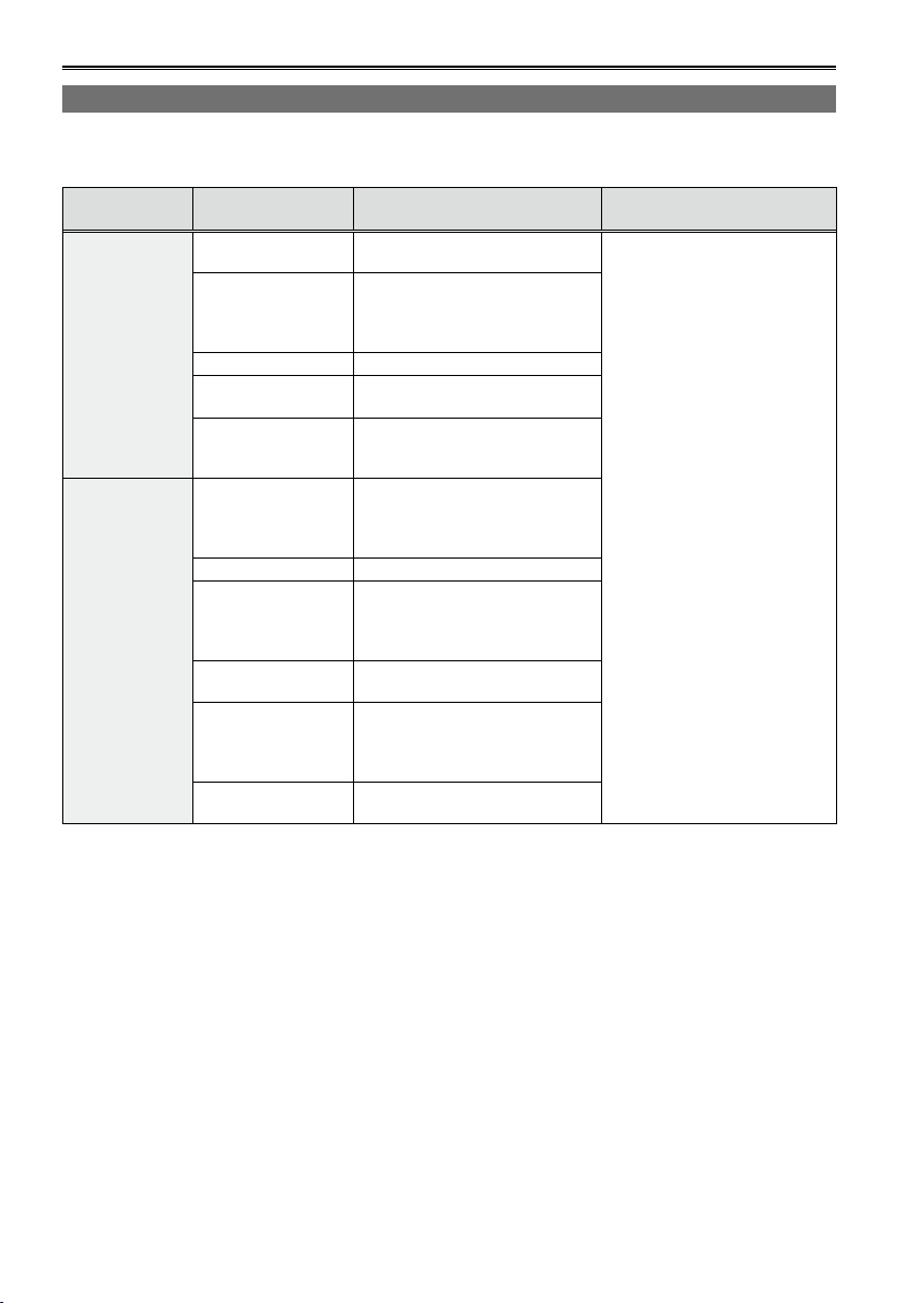
SD Memory Cards compatible with this product
∗
It is recommended that you use SD Memory Cards or SDHC Memory Cards
above, or the following Panasonic SD Memory Cards (correct as of August 2009).
∗
Speed class 4 or above is required for recording in PH mode or HA mode.
Card type Recording capacity Recording/playback
8 MB
16 MB
32 MB
64 MB
128 MB
SD Memory
Card
SDHC Memory
Card
Please see our support page at the following website for the latest information not included in these
•
256 MB
512 MB RP-SDV512
1 GB
2 GB
4 GB
6 GB RP-SDM06G
8 GB
12 GB
16 GB
32 GB
Cannot be used.
Successful operation cannot be
guaranteed. Recording may be
suddenly terminated with certain
SD Memory Cards.
RP-SDV01G
RP-SDM01G
RP-SDV02G
RP-SDM02G
RP-SDP02G
RP-SDV04G
RP-SDM04G
RP-SDW04G
RP-SDP04G
RP-SDV08G
RP-SDM08G
RP-SDW08G
RP-SDP08G
RP-SDM12G
RP-SDP12G
RP-SDV16G
RP-SDM16G
RP-SDW16G
RP-SDP16G
RP-SDV32G
RP-SDW32G
operating instructions.
https://eww.pavc.panasonic.co.jp/pro-av/
This product is compatible with SD Memory Cards formatted under the SD-standard FAT12 and FAT16
•
formats, and with SDHC Memory Cards formatted under the FAT32 format.
Only SDHC Memory Cards may be used for capacities of 4 GB or greater.
•
4 GB (or greater) memory cards without the SDHC logo are not based on the SD standard.
•
Use this product to format the SD Memory Cards to be used. Formatting memory cards on computers
•
or other devices may cause recording to take longer than normal, or may cause cards to become
incompatible with this product. (Page 36) (Use this product to reformat any cards that have already been
formatted on computers, etc.)
Always install the relevant special adapter when using miniSD/miniSDHC cards with this product. (The
•
product will not operate correctly if only the adapter is inserted – always insert a memory card into the
adapter first.)
MultiMediaCards cannot be used with this product.
•
of SD speed class 2 or
Photo shooting
Loading metadata
Can be used.
12
Page 13
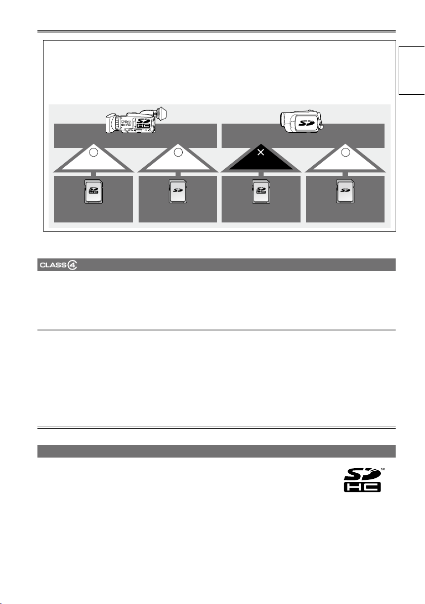
14Precaution for use (continued)
This product (SDHC-compatible device) is compatible both with SD Memory Cards and with
SDHC Memory Cards. SDHC Memory Cards may be used with SDHC Memory Card-compatible
devices, but cannot be used with devices that are only compatible with SD Memory Cards.
(Always check the relevant product’s operating instructions when using SDHC Memory Cards
with other devices.)
Before use
SDHC-compatible device
Can be used Can be used Cannot be used Can be used
SDHC Memory Card SD Memory Card SDHC Memory Card SD Memory Card
SD-compatible device
(SD speed class 4)
This refers to a class 4 speed standard (SD speed class) for the continuous writing of data between SDcompatible devices and SD Memory Cards, as designated by the SD standards.
When the use of an SD speed class 4 card is recommended for SD-compatible products, this indicates
that stable recording operation can be achieved when using SD Memory Cards of class 4 and above.
Cautions for usage
Do not allow dirt, water, or other substances to come into contact with the connector part on the
•
reverse of the card.
Do not leave the card in the following places:
•
– In direct sunlight or in places of high humidity, e.g. close to heating equipment
– In highly humid or dusty locations
– In locations with high variations in temperature (condensation may appear on card)
– In places subject to static electricity or electromagnetic waves
Store cards in bags or cases after use.
•
SDHC Memory Cards
SDHC Memory Cards cannot be used with non-SDHC-compatible equipment.
●
Ensure that all equipment is SDHC-compatible when using card with other devices.
●
13
Page 14

Compatibility of recorded video
Recorded video cannot be used with non-AVCHD-compatible
●
equipment. For details, please see your product’s operating
instructions.
Recorded video cannot be played back on non-compatible (non-
●
AVCHD-compatible) equipment.
Playback may not always be possible on all AVCHD-compatible
●
equipment. Please use this product for playback in such instances.
Older, non-AVCHD-compatible
DVD recorder or DVD player, etc.
About AVCHD
AVCHD is a standard for the recording and playback of highly detailed, high-definition video.
●
Video is compressed in the MPEG-4 AVC/H.264 formats, and audio is recorded in Dolby Digital.
●
Page 15
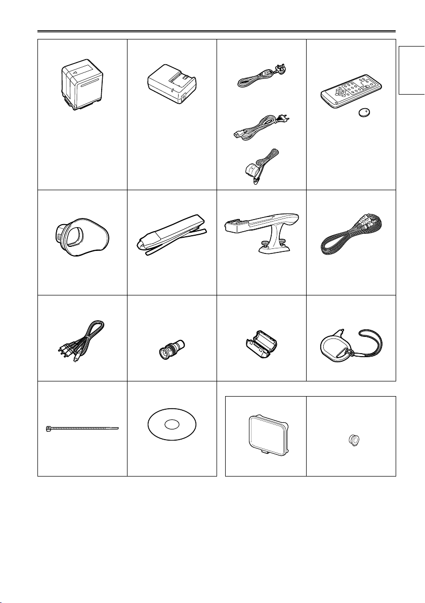
Accessories
∗1
Battery
AC Adapter
AC power supply cables
(For the U.K.)
Wireless remote
control and battery
(CR2025)
Eye cup
→ See “Fitting the eye
cup”. (Page 25)
Component video
cable
Shoulder strap
→ See “Attaching the
shoulder strap”.
(Page 24)
PIN-BNC conversion
plugs (3)
(For areas other than
the U.K.)
DC cable
Handle
→ See “Attaching the
handle”. (Page 25)
Ferrite core (4)
∗2
Before use
AV cable
Touch pen
Cable ties (4)
→ See "”Attaching
cable ties”.
(Page 84)
∗1
For part numbers for the battery, see “Optional accessories”. (Page 16)
∗2
When using a USB connection cable (optional) or HDMI cable (optional), make sure to attach ferrite
cores to the ends of the cable. Failure to attach ferrite cores could cause interference with nearby
equipment. (Pages 83, 84)
Please consult a retailer when purchasing additional accessories.•
CD-ROM
The following accessories are attached to the unit.
Lens hood cap XLR connector cap
15
Page 16
Optional accessories
Super-directional Electret Microphone
•
AG-MC200G
XLR Microphone Adapter
•
AG-MYA30G
Battery
•
VW-VBG130 (7.2 V, 1320/1250 (typ./min.) mAh: compatible with supplied battery charger)
VW-VBG260 (7.2 V, 2640/2500 (typ./min.) mAh: equivalent to accessory battery)
VW-VBG6 (7.2 V, 5800/5400 (typ./min.) mAh: compatible with supplied battery charger)
Tele conversion lens
•
VW-T4314H (See below for attachment instructions.)
Wide conversion lens
•
VW-W4307H (See below for attachment instructions.)
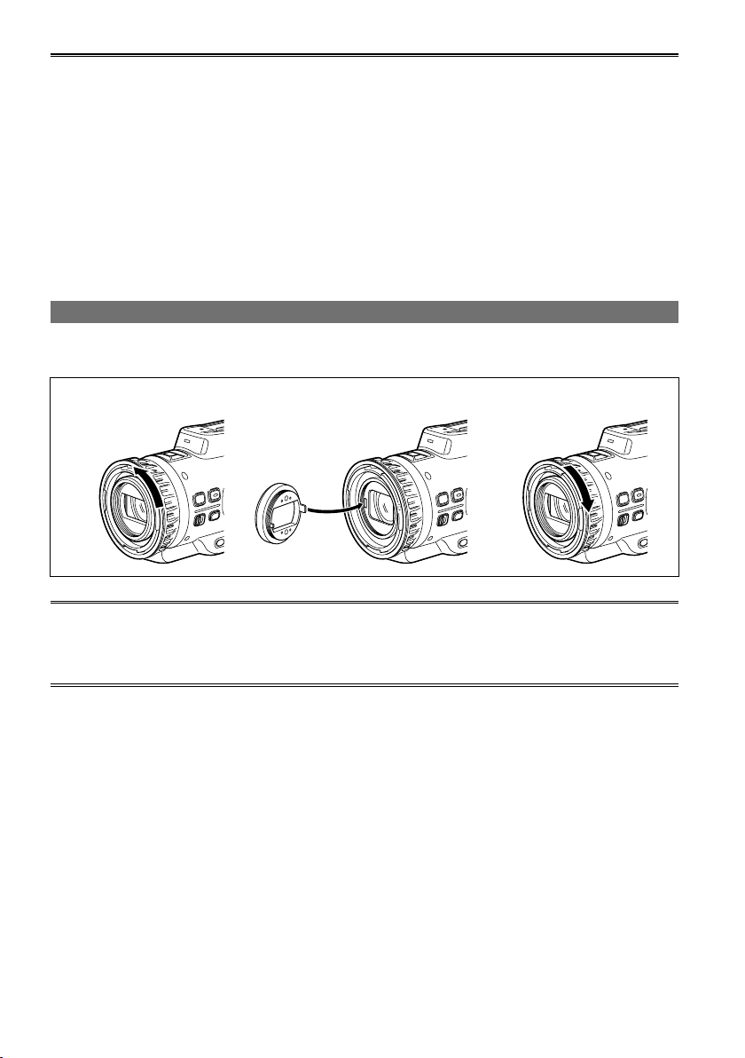
Using tele conversion lenses, wide conversion lenses
Remove both the inner lens hood and outer lens hood before attaching an optional VW-T4314H tele
conversion lens or VW-W4307H wide conversion lens.
Remove Attach Align the grooves.
Attach the ND filter and MC protector to the front of the lens hood (inner).
•
Although you can attach both a filter and a conversion lens at the same time (such as attaching both
•
an ND filter and a tele conversion lens), we do not recommend it, as the corners of images may
appear darker (vignetting) during wide-angle zoom. (If you do attach both at the same time, remove
the lens hood (inner) first.)
16
Page 17
Description of parts
PB
O
F
F
O
N
M
O
D
E
POWER
QUICK START
PHOTO
CAMERA
A/V OUT
COMPONENT
OUT
CAM REMOTE
ZOOM S/S
FOCUS IRIS
PB
O
F
F
O
N
M
O
D
E
POWER
QUICK START
PHOTO
CAMERA
8
72 3 4 5 61
1110
12
9
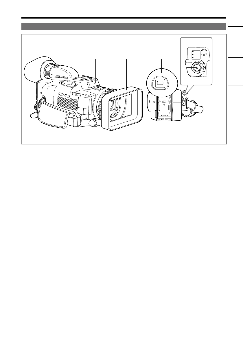
Right side and rear side
1 REC CHECK/PHOTO button (Page 61)
2 Zoom lever (Page 38)
3 Tally lamp (Page 27)
Remote control sensor (Page 26)
4 Built-in mic (Page 53)
5 Lens hood (inner) (Page 16)
6 Lens hood (outer) (Page 16)
7 Viewfinder (Page 29)
8 Battery compartment (Page 23)
9 START/STOP button (Page 34)
10 Mode lamp (CAMERA, PB, PHOTO)
(Pages 34, 61, 70)
11 QUICK START button (Page 27)
12 POWER switch (Page 26)
Before use
of parts
Description
17
Page 18
Description of parts (continued)
Q.MENU
MENU
VOL
W T
BARS
COUNTER RESET
ZEBRA
17 18
20 21
2322 24 25 26 27
1 2
65 7 9 1211 13 14 16
10
3 4
19
8
15
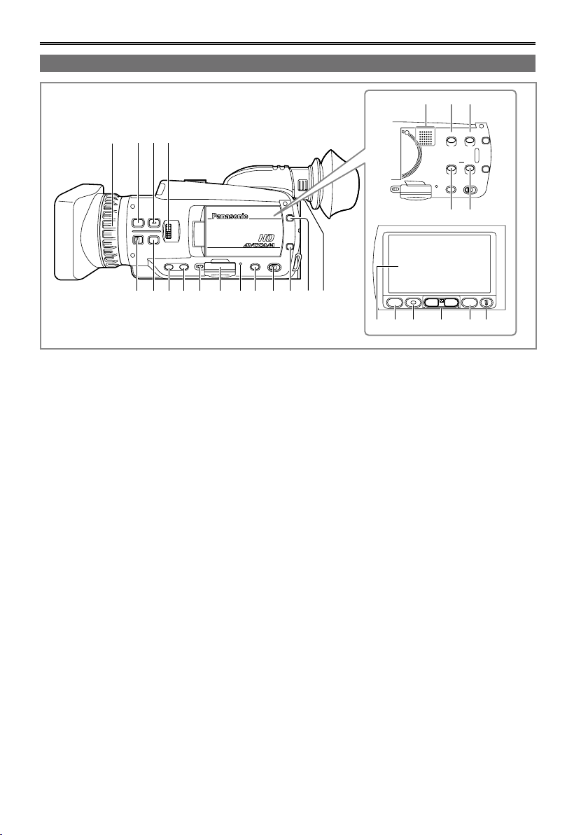
Left side
1 FOCUS ring (Page 40)
2 FOCUS ASSIST button (Page 41)
3 FOCUS button (Page 40)
4 IRIS dial (Page 41)
5 RING switch (Page 40)
6 WHITE BAL button (Page 42)
7 USER1 button (Pages 46, 106)
8 USER2 button (Pages 46, 106)
9 Card cover release lever (Page 33)
10 SD Memory Card cover (Page 33)
11 ACCESS lamp (Page 33)
12 USER3 button (Pages 46, 106)
13 AUTO/MANUAL switch (Pages 34, 40)
14 DISP/MODE CHK button (Page 45)
15 OIS button (Page 46)
16 Diopter adjustment lever (Page 29)
17 Speaker (Page 76)
18 BARS button (Page 47)
19 ZEBRA button (Page 45)
20 COUNTER button (Page 58)
21 RESET button (Page 58)
22 LCD monitor (Page 30)
23 Q.MENU button (Page 96)
24 START/STOP button (Page 34)
25 Zoom buttons (Page 38)
26 MENU button (Page 95)
27 Trash can button (Page 77)
18
Page 19
A/V OUT
COMPONENT
OUT
CAM REMOTE
ZOOM S/S
FOCUS IRIS
PUSH
A/V OUT
COMPONENT
OUT
CAM REMOTE
ZOOM S/S
FOCUS IRIS
USB2.0
MIC
USB2.0
MIC
3
4
8
9
10
11
5
6
7
2
1
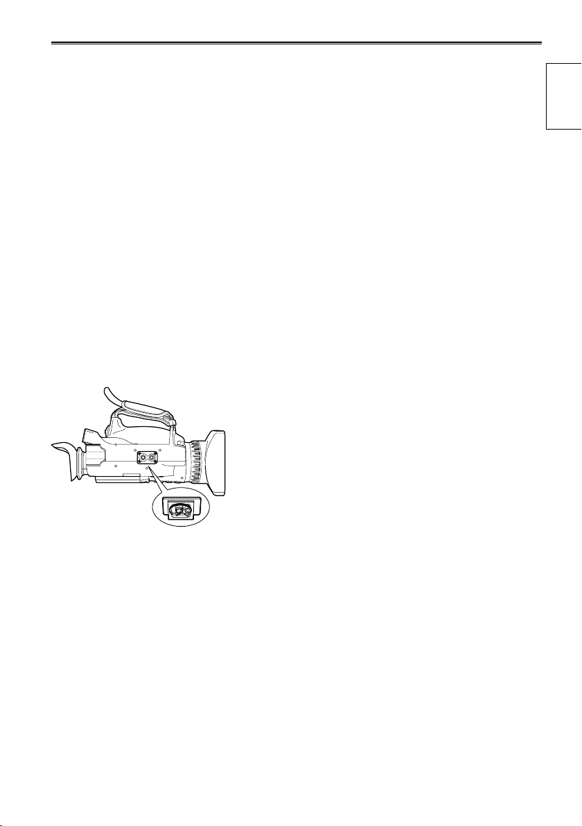
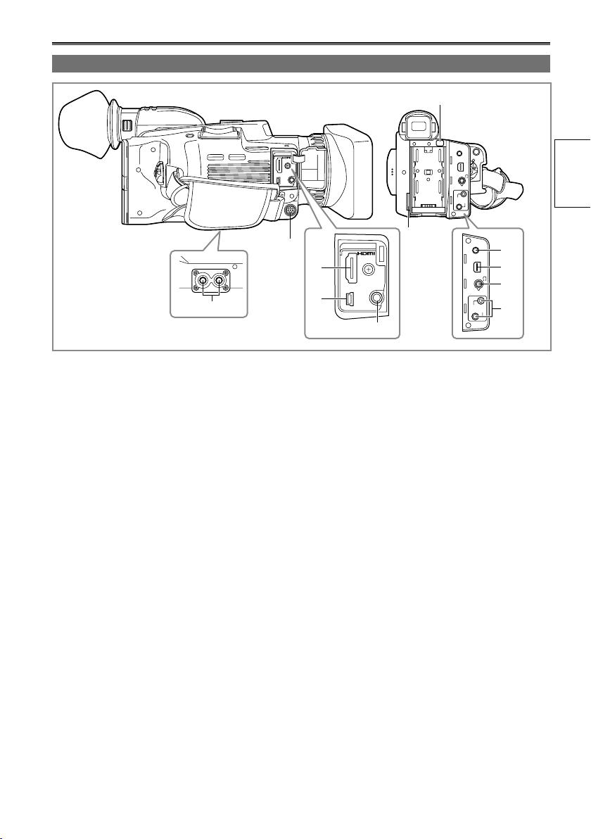
Terminals and mounting parts
1 Tripod hole (Page 11)
2 XLR adapter terminal (Page 82)
3 HDMI terminal (Page 84)
4 USB2.0 terminal (Pages 83, 85)
5 MIC terminal (Page 82)
6 Shoulder strap attachment point (Page 24)
7 Battery release button (Page 23)
8 A/V OUT terminal (Pages 83, 84)
9 COMPONENT OUT terminal (Page 84)
10 Headphone jack (Page 82)
11 CAM REMOTE jacks
FOCUS/IRIS (3.5 mini jack)
You can connect a remote control unit to control
the FOCUS and IRIS (aperture).
IRIS (aperture) control beyond OPEN is
performed via gain adjustment, and can be set
up to the standard gain setting.
ZOOM S/S (2.5 mm super mini jack)
You can connect a remote control unit to control
zoom and start/stop of recording.
∗
of parts
Description
∗
Do not connect any equipment except the remote
controller to the remote control jack. Connecting
any equipment other than the remote control may
cause the image brightness to change and/or the
images to appear out of focus.
19
Page 20
Description of parts (continued)
ZOOM
START/
STOP
PHOTO
SHOT
EXT
DISPLAY
DATE/
TIME
VOL
PLAY
STOPSKIP SKIP
MENU
ENTER
PAUSE
SEARCH
STILL ADV STILL ADV
SEARCH
4
5
7
9
1
2
6
8
9
10
11
13
3
7
12
11
14
15
Remote control
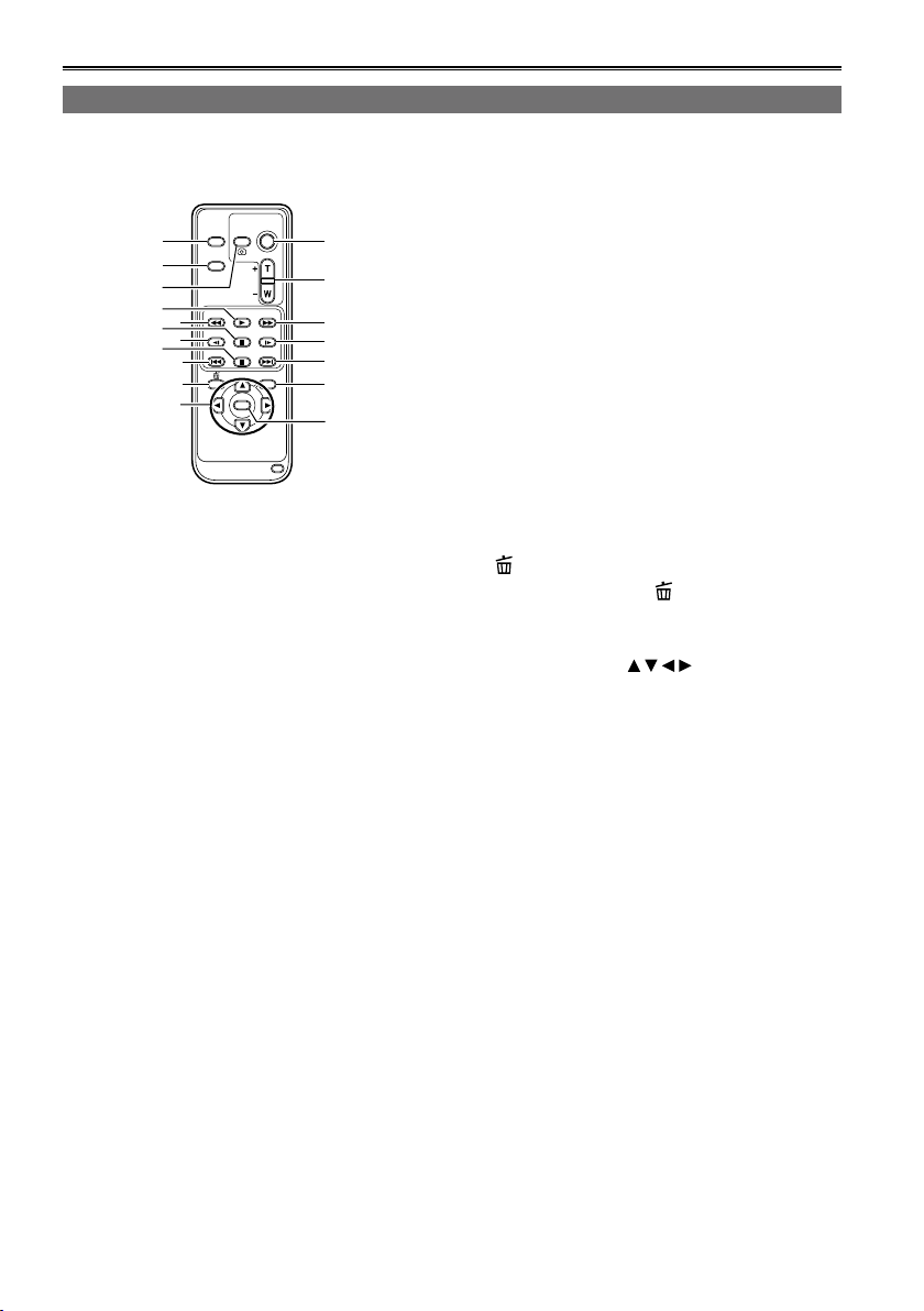
To use the remote control, set the IR REMOTE item on the OTHER FUNCTIONS menu to ON. The default
setting for this item is OFF. (Page 109)
1 EXT. DISPLAY button (Page 76)
2 DATE/TIME button (Page 76)
3 PHOTO SHOT button (Page 61)
Performs only the PHOTO function of the REC
CHECK/PHOTO button on the camera.
4 START/STOP button (Page 34)
Used to select items and change setting
values.
5 ZOOM/VOL buttons (Pages 38, 76)
6 PLAY button (Pages 70, 71, 74)
7 SEARCH buttons (Pages 70)
8 PAUSE button (Page 71)
Remote control usable range (Page 26)
9 STILL ADV buttons (Page 71)
10 STOP button (Pages 70, 74)
11 SKIP buttons (Pages 71)
button (Page 77)
12
Same function as the button on the LCD
monitor.
13 OPERATION buttons
Same function as on the LCD
monitor.
14 MENU button
Same function as the MENU button on the
camera.
15 ENTER button
Used to confirm menus and items.
20
Page 21
Recharging the battery
Recharging
The battery does not come ready charged when the camera is purchased. Charge the battery before use.
It is recommended that you keep one extra battery as a spare.
Charging time and available recording time
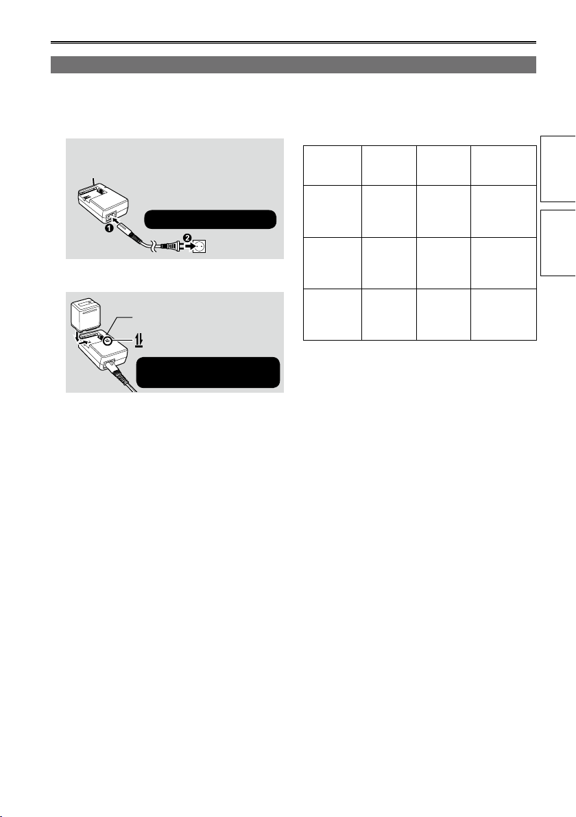
Connect the power cable to the AC adapter.
1
Disconnect the DC cable.
(Battery cannot be charged if DC cable is
connected.)
Insert until fully in place.
Insert the battery.
2
Charging lamp [CHARGE]
Align the battery with the
Charging lamp
■
On: Charging in progress
Off: Charging complete
Flashing: See below
If charging lamp is flashing
■
Check that there is no dirt, dust, or other
substances attached to the connectors on the
battery or AC adapter, and ensure that the adapter
has been connected correctly.
If there is dirt or dust on the connectors,
•
disconnect the power plug from the socket before
cleaning.
If the charging lamp continues to flash, there
•
may be a fault with the battery or the AC adapter.
Please consult with the place of purchase.
mark and insert fully.
■
(Approx.)
Battery
model
VW-VBG130
(optional)
VW-VBG260
(included)
VW-VBG6
(optional)
The figures in the table above are guidelines
•
for use in normal temperature conditions
(temperature 25 °C, humidity 60%). Charging
may take longer in higher or lower temperatures.
Charging may take longer if the battery has not
•
been in use for a long period of time.
Given here are the approximate continuous
•
recording times when recording using the
viewfinder with no connections to any external
devices and with the LCD monitor closed.
Available recording time may vary according to
•
usage conditions.
Charging times are based on charging batteries
•
from an empty state.
Voltage/
capacity
7.2 V/
1320/1250
(typ./min.)
mAh
7.2 V/
2640/2500
(typ./min.)
mAh
7.2 V/
5800/5400
(typ./min.)
mAh
Charging
time
Approx.
1 hr.
25 min.
Approx.
2 hr.
50 min.
Approx.
5 hr.
50 min.
Maximum
continuous
recording time
Approx.
1 hr. 30 min.
Approx.
3 hr. 15 min.
Approx.
7 hr.
of parts
Preparation Description
(Continued on the next page)
21
Page 22

Recharging the battery (continued)
Remaining battery capacity displays
■
When using Panasonic-manufactured batteries
compatible with this product, the remaining battery
capacity is displayed in hours and minutes.
1h30m
Time remaining will be displayed after a brief
pause.
The battery display will change
•
→ → → →
as battery capacity decreases. will be
displayed in red when less than 3 minutes are
remaining, and will flash when the battery
is empty.
Remaining battery capacity may not be displayed
•
correctly when using in high or low temperatures,
or when the battery has not been used for a
long period of time. To ensure that remaining
battery capacity is displayed correctly, use the
battery completely from a fully-charged state,
and charge the battery again. (Remaining battery
capacity may still not be displayed correctly if the
battery has been used for long periods in high
or low temperatures, or if the battery has been
recharged a large number of times.)
The remaining battery capacity display is a
•
guideline and may change according to usage
conditions.
The remaining battery capacity display will
•
momentarily disappear when switching between
modes, when conducting REC CHECK
operations or when changing the LCD brightness
since the capacity is recalculated at these times.
Not displayed when using AC adapter.
•
The maximum time display for the remaining
•
battery capacity is 9 hours 59 minutes.
If the remaining battery capacity exceeds 9 hours
•
and 59 minutes, the remaining time is displayed
in green. This display does not change until the
remaining time reaches 9 hours and 59 minutes
and below.
Keep metal objects (such as necklaces and
•
hairpins) away from the battery.
Short-circuiting may occur across the
terminals, causing the battery to heat up,
and you may seriously burn yourself if you
touch the battery in this state.
The battery becomes hot while it is being used
•
or charged. The camera-recorder itself also
becomes hot during use.
The recordable time reduces if you repeatedly
•
start and stop recording.
The battery takes longer to charge when it is
•
warm.
The AC adapter can interfere with radio
•
reception so keep radios at least 1 meter away
from it.
The AC adapter may make some noise when
•
you are using it, but this is normal.
Battery cannot be recharged when the DC
•
cable is connected to the AC adapter.
22
Page 23
Power sources
ヱャ
ヲヶリヤレチヴヵモン
ヵ
ヱラヰヵ
ヰ
ヤモヮユン
モ
ヱャ
ヱヰヸユ
ン
ヲヶリヤレチヴヵモン
ヵ
ヱラヰヵ
ヰ
ヤモヮユン
モ
2$
1
(
(
1
0
/
1
&
'
219'4
37+%-56#46
2*161
%#/'4#
#8176
%1/210'06
176
%#/4'/16'
<11/55
(1%75+4+5
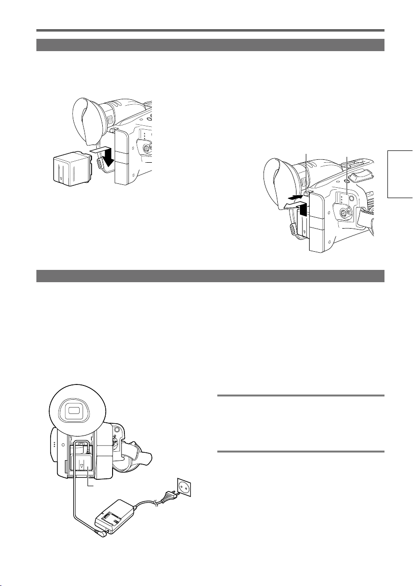
Using the battery
Installation
Insert the battery until it clicks into place.
Using the AC adapter
Installation
Connect the DC cable to the AC adapter.
1
Plug the AC power supply cable into the
2
power outlet.
Insert the DC cable’s battery connector until
3
it clicks into place.
Removal
Set the POWER switch to OFF, and check
1
that the mode lamp is off.
Remove the battery while pressing the
2
battery release button.
Support the battery with your hand to ensure
•
that it will not fall.
Mode lampBattery release button
Removal
Set the POWER switch to OFF, and check
1
that the mode lamp is off.
Remove the DC cable’s battery connector
2
while pressing the battery release button.
Disconnect the AC power supply cable from
3
the power outlet.
Preparation
Battery cannot be recharged when the DC
•
cable is connected to the AC adapter.
CAUTION:
Disconnect the AC power supply cable from the
•
power outlet when the unit is not going to be used.
DC cable’s battery
connector
23
Page 24
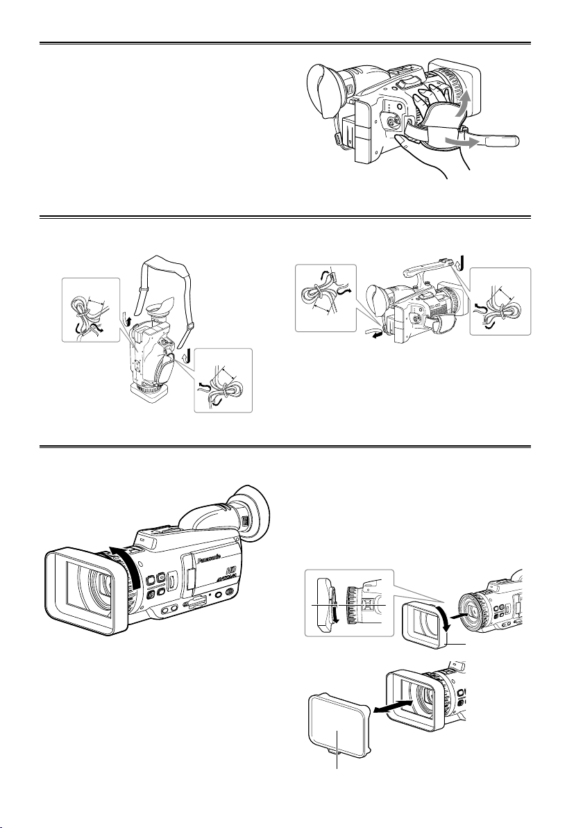
Adjusting the hand strap
ヱャ
ヲヶリヤレチヴヵモンヵ
ヱラヰヵヰ
ヤモヮユンモ
ヱヰヸユ
ン
Adjust the hand strap to suit your hand.
Open the cover and adjust the length.
1
Close the cover.
2
Make sure the cover is fully closed.•
Attaching the shoulder strap
Attach the shoulder strap and use it as a precaution against dropping the camera.
When the handle is not attached
20 mm or
more
20 mm or
more
When the handle is attached
20 mm or more
20 mm or
more
Detaching and attaching the lens hood
Detaching the lens hood
Turn the lens hood counterclockwise to detach it.•
24
Attaching the lens hood
Orient the lens hood with the arrow mark on top,
•
rotate the hood counterclockwise (approx. 14˚) to
align the arrow with the one on the camera, and
then slide the hood onto the camera.
Rotate the lens hood clockwise to attach it.
•
Be sure to attach the lens hood cap to protect the
•
lens when not in use.
Lens hood cap
Lens hood
Page 25
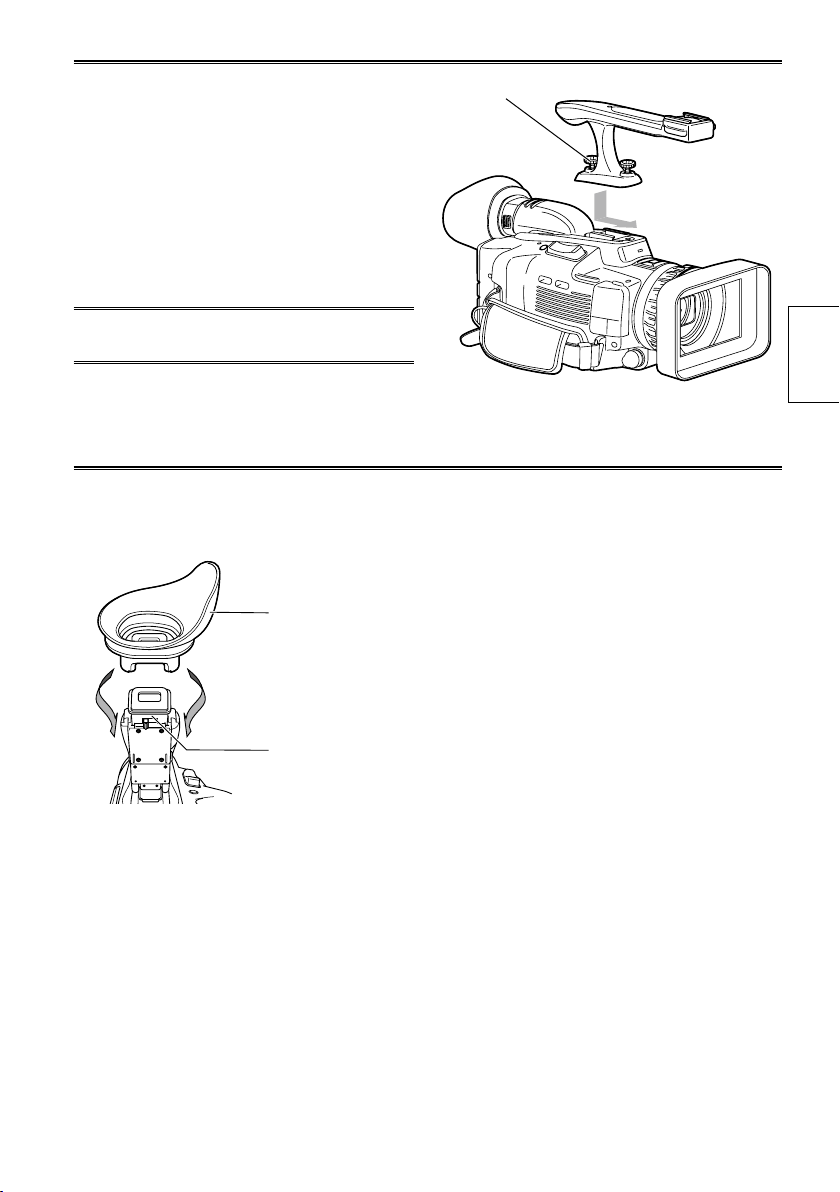
Attaching the handle
The handle comes in handy for taking low-angle
shots or carrying the camera-recorder around.
Pull the viewfinder towards you.
1
Slide the handle into place.
2
Tighten the coin screw to secure the handle
3
firmly.
If the coin screw is loose, the camera-
•
recorder may drop off.
To remove the handle, first pull the viewfinder
•
towards you, and then loosen the coin screw.
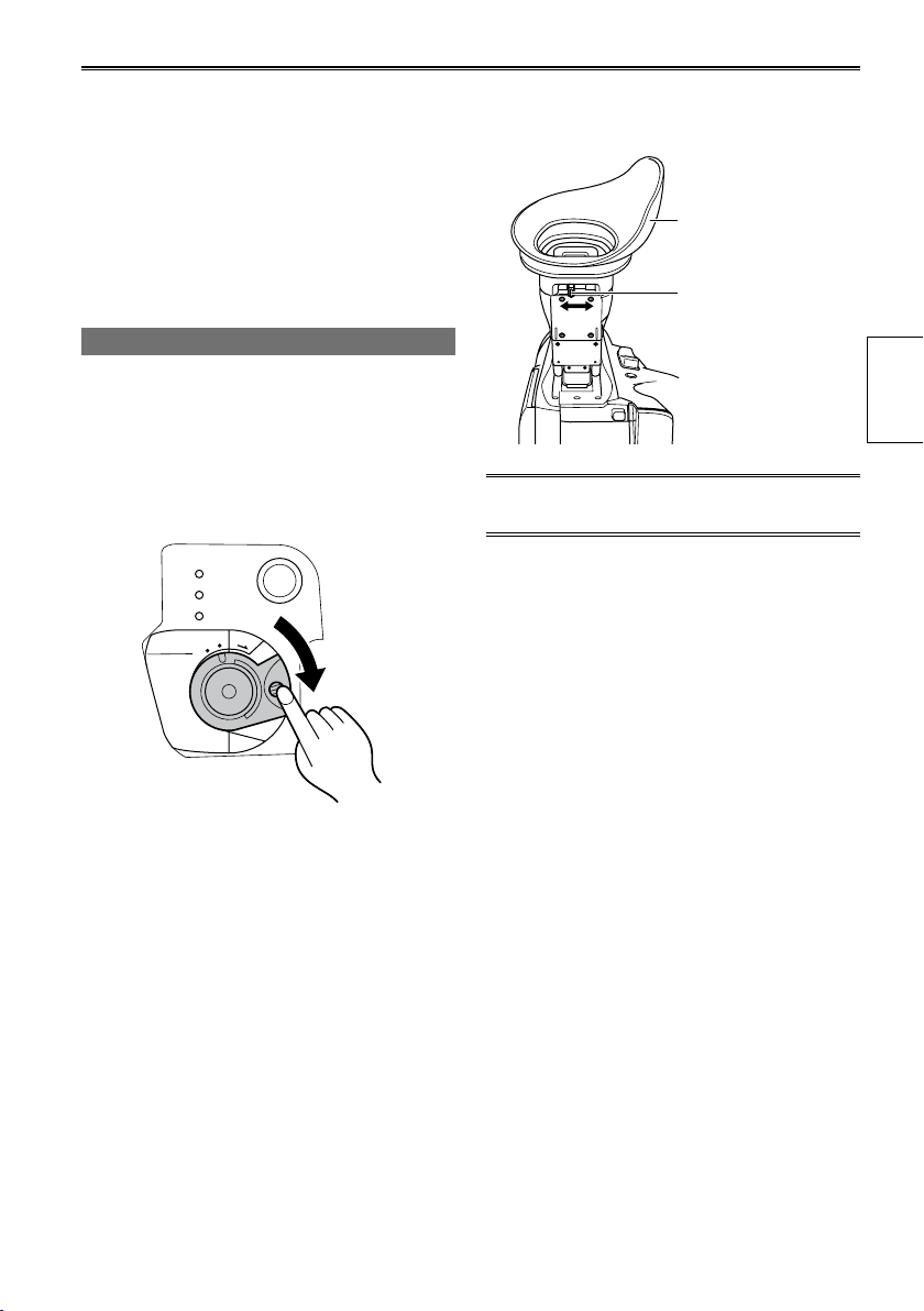
Fitting the eye cup
Attach the eye cup by aligning the projections on
the eye cup holder and eye cup and fitting them
together.
Eye cup
Coin screw
Preparation
Eye cup holder
Fit the eye cup onto the viewfinder, and secure it in
the direction of the arrow.
25
Page 26
The remote control
PB
Q
U
IC
K
S
T
A
R
T
PHO
T
O
C
A
M
E
R
A
P
O
W
E
R
PB
O
F
F
O
N
M
O
D
E
POWER
QUICK START
PHOTO
CAMERA
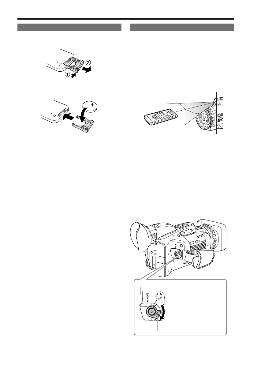
Insert the battery
Push the catch in the direction shown by
1
arrow ① to remove the holder.
Insert the battery with the “+” marked side
2
facing up.
Return the holder to its original position.
3
•
When the battery (CR2025) has run out, replace
it with a new one. (The battery lasts about one
year, depending on the frequency of use.)
If the remote control unit fails to work even when
it is operated near the camera-recorder’s remote
control sensor, the battery has run out.
Keep the battery out of the reach of children.
•
Remote control usable range
The distance between the remote control and the
unit’s remote control sensor: Within approx. 5 m
Angle: Approximately 15° upward,
approximately 10° downward,
approximately 15° leftward, or
approximately 15° rightward
(Except when optional accessories are
attached)
Remote control
sensor
The remote control is intended for indoor operation.
•
Outdoors or under strong light, the unit may not
operate properly even within the usable ranges.
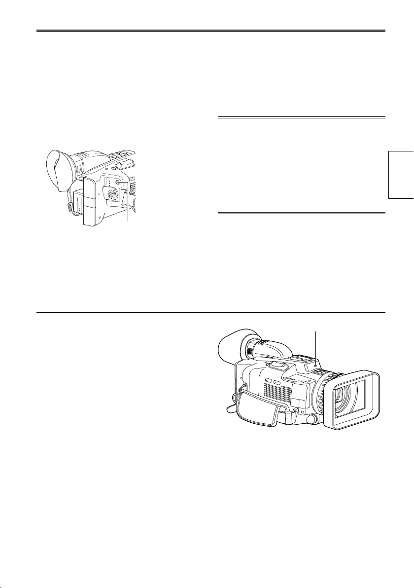
Turn on/off the camera
While pressing the lock release button, move the
POWER switch to ON or OFF.
Turn on the camera:
The mode lamp (CAMERA) lights red (camera
mode), and the camera enters recording standby
mode.
Turn off the camera:
The mode lamp (CAMERA) goes out.
Energy-saving mode
•
According to the settings made in the POWER
SAVE item of the OTHER FUNCTIONS screen
in the settings menu, the following will apply if
no designated operations∗ are performed for
approximately five minutes in recording standby
mode (when an SD Memory Card has been inserted
while using the battery).
ON:
OFF: Does not switch OFF the camera.
∗
See the setup menus, POWER SAVE
(Page 110) for details.
26
The camera recorder turns off automatically.
Mode lamp
POWER switch
Set the POWER switch to the
ON position while pressing the
lock release button.
The CAMERA lamp lights (red),
and the camera enters recording
standby mode.
Lock release button
Page 27
Quick Start mode
ヱャ
ヱヰヸユ
ン
ヲヶリヤレチヴヵモン
ヵ
ヱラヰヵ
ヰ
ヤモヮユン
モ
This mode allows you to begin recording more quickly.
When using Quick Start mode, you can begin
recording approximately 1.5 seconds after Quick Start
standby mode.
Setting
■
Hold down the QUICK START button for at least
two seconds while the power is on. The camera
will enter Quick Start standby mode and the
CAMERA and PHOTO lamps will flash.
QUICK START button
To start recording
■
When the QUICK START button is pressed in
the Quick Start standby mode (lamps flashing),
the lamps light and the camera enters recording
standby mode.
Tally lamp
You can set the tally lamp to light in the following
situations by setting the REC LAMP item
(Page 109) in the OTHER FUNCTIONS screen to
ON.
Battery is low (flashes 4 times per second)
•
Available SD Memory Card capacity is low
•
(flashes 4 times per second)
Remaining battery capacity is low
•
(flashes once per second)
Remaining memory of the SD Memory Card is
•
low (flashes once per second)
In addition, the tally lamp will flash regardless of
the REC LAMP setting when receiving commands
from the remote control.
Quick Start mode will be canceled in the
•
following cases.
The camera remains in Quick Start standby
�
mode for more than 30 minutes
Battery is low
�
Battery has been removed
�
POWER switch is set to OFF
�
Quick Start standby mode consumes
•
power, resulting in reduced total recording
time.
Depending on recording settings, Quick Start
•
may take longer than 1.5 seconds.
Automatic white balance adjustment may take
•
longer in Quick Start mode.
The zoom ratio will be set to approximately x 1
•
wide end (Z00) with Quick Start.
Tally lamp
Preparation
27
Page 28
Touch panel
This camera utilizes a touch panel LCD monitor.
You can navigate setting menus and other displays
by touching items in the LCD monitor directly.
Using the touch panel
Icons are selected when you release your finger
from the touch panel after pressing them.
If you touch another part of the screen without
•
removing your finger from the touch panel, the
selection will not be made.
Use the touch pen (supplied) if you have difficulty
•
making precise selections with your fingers. Do
not use touch pens other than the one supplied.
Frequently used icons
:
Touch these to scroll through the pages of menu
and thumbnail screens or to adjust setting values.
Example:
:
Touch this to return from a function or setting
screen to a previous screen.
Example:
Use soft cloth, such as glasses cleaning cloth,
•
to clean or wipe fingerprints off of the LCD
monitor.
Do not use ballpoint pens or other pointed
•
objects to touch the LCD monitor.
Do not touch the LCD monitor with your
•
nails or scratch and press the monitor with
excessive force.
Applying a protective sheet to the LCD monitor
•
may reduce visibility and touch recognition.
If your touch is not recognized or other
•
parts of the screen are recognized, adjust
the CALIBRATION item in the OTHER
FUNCTIONS screen. (Page 31)
28
Example:
Page 29
ヱャ
ヰ
ョ
ョ
チ
ヰ
ワ
チ
ヮ
ヰ
ュ
ユ
ヱヰヸユン
ヲヶリヤレチヴヵモンヵ
ヱラヰヵヰ
ヤモヮユンモ
Viewfinder
This camera has two viewfinders; one is a
miniature LCD in the viewfinder and the other is a
retractable 2.7-inch LCD.
Use the viewfinder that best suits the application
and shooting conditions.
The brightness and hue may differ between the
•
images appearing on the viewfinder and LCD
monitor and those displayed on a TV monitor. To
see how the final images will appear, check them
on a TV monitor.
Using the viewfinder
Set the POWER switch to ON, and check
1
that images appear in the viewfinder.
Leave the LCD monitor closed.
•
You can display images in both the LCD
•
monitor and viewfinder at the same time by
setting the EVF MODE item in the setting
menu SW&DISP SETUP screen to ON.
Adjust the diopter adjustment lever until
3
text display in the viewfinder is clear.
Eye cup
Diopter adjustment
lever
Do not point the viewfinder directly at the sun.
•
Doing so may damage internal components.
Preparation
Adjust the angle of the viewfinder to a
2
convenient viewing position.
The viewfinder can be raised to about 70˚
•
from the camera.
29
Page 30
Viewfinder (continued)
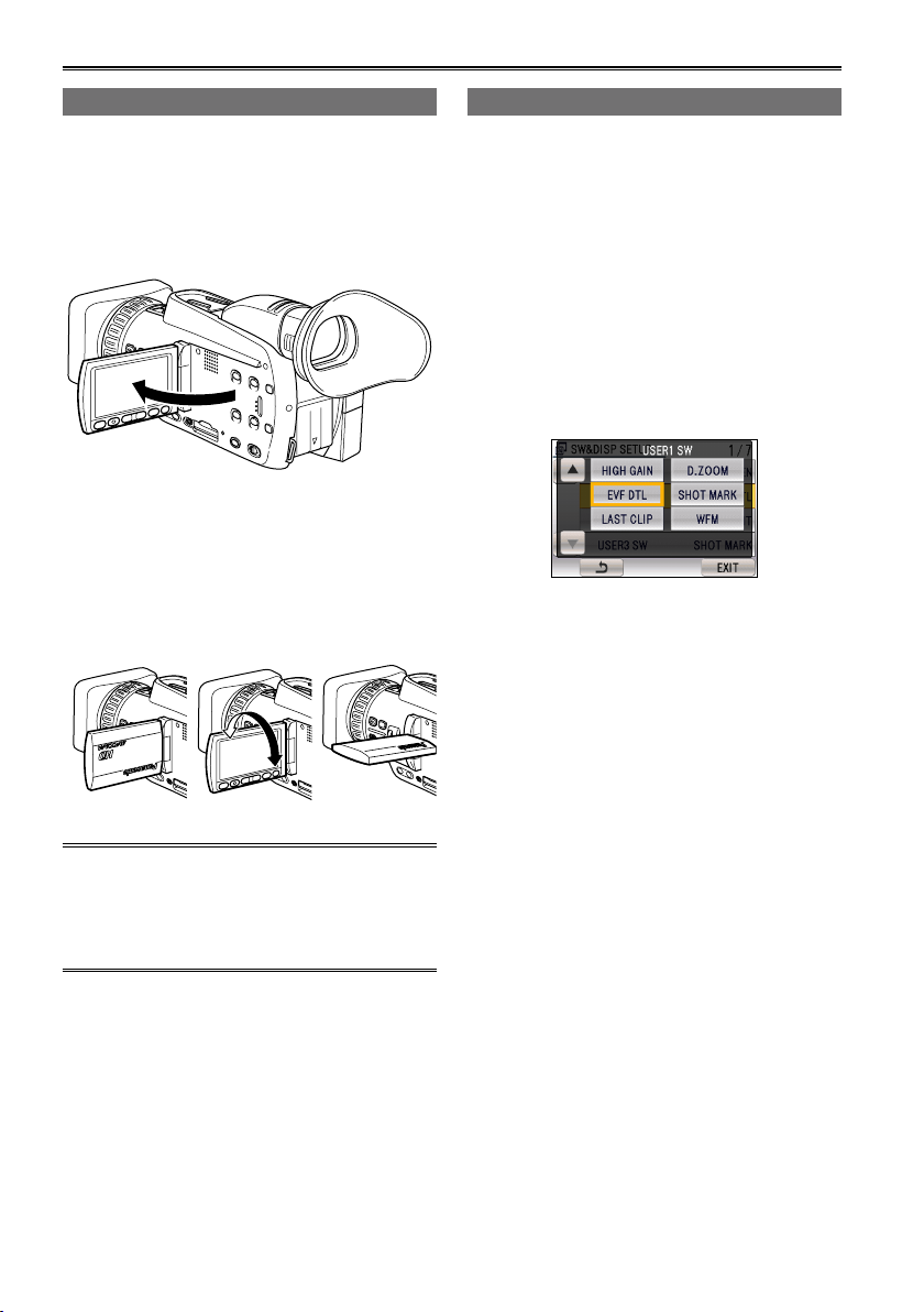
Using the LCD
Set the POWER switch to ON. (Page 26)
1
Open the LCD monitor.
2
The monitor opens up to 90°. Attempting to
open it further with force may damage the
camera.
90°
Adjust the angle of the LCD monitor to a
3
convenient viewing position.
The monitor can be rotated 180° toward the
•
lens and 90° toward the eye piece.
Attempting to rotate it further with force
•
or closing it in a 90° position may damage
the camera.
180° 90°
Emphasizing outlines
When EVF DTL is assigned to one of the USER
buttons 1 to 3, you can press that button to
emphasize the outlines of images in the viewfinder
or LCD monitor, and make focus alignment easier.
Emphasizing the outlines does not effect the
images you shoot.
Touch USER1 SW, USER2 SW, or USER3
1
SW in the setting menu SW&DISP SETUP
screen.
Touch EVF DTL.
2
EVF DTL is assigned to the selected USER
button.
In CAMERA mode or PHOTO mode, press
3
the USER button assigned to EVF DTL.
“EVF DTL ON” appears in the center of the
screen for about 2 seconds.
To release the setting, press the USER button
assigned to EVF DTL again, and “EVF DTL
OFF” appears in the center of the screen for
approximately 2 seconds.
When closing the LCD monitor, be sure to
•
close it fully.
When the LCD monitor is facing the lens
•
(during self-portrait recording), both the
viewfinder and the LCD monitor will be lit.
30
Page 31

Adjusting the screen display
Set the POWER switch to ON. (Page 26)
1
Press the MENU button.
2
Menu operation (Page 95)
•
Operations may also be performed
•
using buttons on the remote control that
correspond to those on the camera. For
details, see “Description of parts (Remote
control)”. (Page 20)
Viewfinder adjustments
3
Set YES under EVF SET on the setting menu
SW&DISP SETUP screen.
LCD monitor adjustments
Set YES under LCD SET on the setting menu
SW&DISP SETUP screen.
Touch or to adjust the selected item.
5
Touch ENTER.
6
Touch EXIT or press the MENU button to
•
finish configurations.
The viewfinder display can be in color or black
•
and white. (See the setup menus, SW&DISP
SETUP screen, EVF COLOR.) The resolution
is the same for both of them.
Adjusting the touch panel
Adjust touch panel calibration if items that you do
not intend to select are selected when you touch
the panel.
Touch YES for CALIBRATION in the setting
1
menu OTHER FUNCTIONS screen.
Touch ENTER when the confirmation
•
message appears.
Preparation
Touch the item you want set.
4
Touch [+] using the supplied touch pen.
2
Touch [+] as they appear (5 total).
•
Touch ENTER.
3
You cannot perform adjustment when the
•
LCD monitor is rotated 180°.
31
Page 32

Setting the calendar
The CLOCK SET value is recorded in the contents
(clip), and affects the sequence of playback of the
thumbnails. Before carrying out recording, be sure
to check and set CLOCK SET and TIME ZONE.
This shows you how to adjust the calendar to
17:20 on December 25, 2009.
Setting the time zone
Set the POWER switch to ON. (Page 26)
1
Press the MENU button.
2
Menu operation (Page 95)
•
Operations may also be performed
•
using buttons on the remote control that
correspond to those on the camera. For
details, see “Description of parts (Remote
control)”. (Page 20)
Touch YES for TIME ZONE in the setting
3
menu OTHER FUNCTIONS screen.
Touch the time zone display, and touch or
4
to select the difference from Greenwich
Mean Time.
The factory default setting is +0:00.
•
Touch ENTER.
5
The clock can vary in accuracy, so check that
•
the time is correct before shooting.
When using the camera overseas, do not
•
set the CLOCK SET option to the local time,
but enter the time difference from Greenwich
Mean Time using the TIME ZONE option
instead. (Page 109)
Setting the clock
Set the POWER switch to ON. (Page 26)
1
Press the MENU button.
2
Menu operation (Page 95)
•
Operations may also be performed
•
using buttons on the remote control that
correspond to those on the camera. For
details, see “Description of parts (Remote
control)”. (Page 20)
Touch YES for CLOCK SET in the setting
3
menu OTHER FUNCTIONS screen.
Touch the item you want to set, and touch
4
or to set the value.
Repeat the procedure from step 4 to set the
5
remaining items.
The date can be set to any date between
•
January 1, 2001 and December 31, 2039.
“--.--.----” is displayed for any date beyond
•
December 31, 2039.
The time is displayed in 24-hour format.
•
Touch ENTER.
6
Touch EXIT or press the MENU button when
7
you are finished configuring items.
32
Page 33

SDCAR
D
Basic shooting operations
Preparing for recording
Set the camera’s power switch to OFF.
1
(Page 26)
Check that the mode lamp is off.
•
Slide the card cover release lever, and open
2
the SD Memory Card cover.
Slide to the
left to open.
Fully insert an SD Memory Card into the
3
card slot.
Insert the card in the direction shown until it
•
clicks into place.
ACCESS lamp
· Flashes during SD
Memory Card access
(recognition, recording,
playback, deletion, etc.).
For details, see “SD
Memory Card ACCESS
lamp”.
Do not perform any of the following operations
•
while the SD Memory Card ACCESS lamp is
flashing.
Performing these operations may damage the
SD Memory Card or its contents, or cause the
camera to fail to operate correctly.
Opening the card door and removing the SD
�
Memory Card
Switching off the power
�
Removing the battery
�
Connecting or disconnecting the USB
�
connection cable
Shaking or striking the camera
�
Always format SD Memory Cards that have
•
been used in other devices when first using
them with this camera. (Page 35)
If “CHECK CARD” is displayed on the
•
viewfinder or the LCD monitor, please remove
the SD Memory Card and insert it again.
SD Memory Card ACCESS lamp
This lamp lights or flashes during memory card
access.
Lit: Card inserted, read/write possible
Flashing (fast): Recognizing
Flashing (slow): Accessing (during recording/
playback/reading)
Off: Card not inserted, unformatted card inserted
SD Memory Card access lamp
Shooting Preparation
Close the SD Memory Card cover.
4
Ensure that the cover firmly clicks into place.
•
33
Page 34

Basic shooting operations (continued)
A
ヱャ
ヲヶリヤレチヴヵモン
ヵ
ヱラヰヵ
ヰ
ヤモヮユンモ
ヱヰヸユ
ン
ヱャ
ヰ
ョ
ョ
チ
ヰ
ワ
チ
ヮ
ヰ
ュ
ユ
ヱヰヸユン
ヲヶリヤレチヴヵモンヵ
ヱラヰヵヰ
ヤモヮユンモ
AUTO MANUAL
ヱャ
ヰ
ョ
ョ
チ
ヰ
ワ
チ
ヮ
ヰ
ュ
ユ
ヱヰヸユン
ヲヶリヤレチヴヵモンヵ
ヱラヰヵヰ
ヤモヮユンモ
Shooting in auto mode
Turn the POWER switch to ON. (Page 26)
1
Check that the mode lamp (CAMERA) is
•
lighted red.
Switch the AUTO/MANUAL switch to AUTO
2
to select auto mode.
appears on the viewfinder and LCD
•
monitor.
The focus, shutter speed, gain, iris, and
•
white balance are adjusted automatically.
In addition, if the AUTO SW item in the
setting menu SW&DISP SETUP screen is set
to FACE DETECT ON, focus is automatically
aligned on faces detected in the image and
brightness is adjusted for optimal results.
appears when FACE DETECT ON is set.
Up to 15 face detection frames can be displayed
•
on the screen at one time. Larger frames and
frames closer to the center have priority.
When FACE FRAMING is set to ALL and
•
multiple subjects are detected, only the
frame on which focus is aligned is displayed
in orange. All other frames are displayed in
gray.
Primary (priority) frames
•
The primary frame is displayed in orange.
Focus is automatically aligned to the primary
frame, and the brightness is adjusted.
When you press the REC CHECK/PHOTO
button halfway in PHOTO mode, focus is
aligned to the primary frame.
When focus is aligned, the primary frame
turns green.
Press the START/STOP button (Red) to start
3
shooting.
•
Press again to enter recording standby
mode.
Shooting is not possible when a menu screen
•
is displayed. First, close the menu screen,
and then press the START/STOP button.
Shooting stops when the SD Memory Card
•
cover is opened during shooting.
Lock release button
1 3
Mode lamp
2
The images shot from when shooting starts
•
until it is stopped are recorded as one clip.
When recording is paused after a short period,
•
a small amount of time may be required after
pressing the START/STOP button to stop
recording before writing to the SD Memory
Card is terminated.
This means that operations cannot be
accepted if the START/STOP button is
pressed immediately.
The camera will read information from the SD
•
Memory Card immediately after the card is
inserted. Press the START/STOP button to
begin recording after (pause) is displayed in
the operation status display. (Page 87)
The camera’s factory default setting is PH
•
mode 1080/50i recording.
(To view current setting status: Page 45)
The upper limit for the number of clips which
•
can be recorded on a single SD Memory Card
is 900. (However, this number may exceed
900 clips at times such as when shooting
immediately after the POWER switch has been
set to ON.)
34
Page 35

Checking photos taken (REC CHECK)
Press the REC CHECK/PHOTO button while in
recording standby mode. The last two seconds of
video and audio will be played, and the camera
returns to recording standby mode.
Only the POWER and START/STOP buttons are
•
operable during REC CHECK.
The REC CHECK images are also recorded
•
when a device is connected to the camera and
backup images have been recorded.
The REC CHECK function does not work when
•
PB has been selected as the operation mode or
when connected to a computer.
This function also does not work if the REC
•
FORMAT has been changed or if the camera has
been set to CAMERA mode after having switched
to PB mode after recording.
The REC CHECK function does not work after
•
interval recording.
This function does not work if the SD Memory
•
Card is removed and reinserted.
Formatting SD Memory Cards
Set the camera’s power switch to ON.
1
(Page 26)
Shooting
Press the MENU button.
2
Touch YES for CARD FORMAT in the setting
3
menu OTHER FUNCTIONS screen.
Press the MENU button or touch EXIT to
•
close the menu display.
Touch YES on the confirmation screen.
4
The SD Memory Card will be formatted.
•
Touch EXIT.
5
When an SD Memory Card is formatted, all
•
data recorded on the card will be erased and
will not be restorable.
Save all important data to your computer.
35
Page 36

Basic shooting operations (continued)
SD Memory Card recording times
Total available recording times (approx.) when using SD/SDHC Memory Cards manufactured by Panasonic
∗1
SD Memory Card
capacity
512 MB Approx. 2 min Approx. 3 min Approx. 4 min Approx. 10 min
1 GB Approx. 5 min Approx. 7 min Approx. 9 min Approx. 21 min
2 GB Approx. 10 min Approx. 15 min Approx. 20 min Approx. 45 min
4 GB Approx. 21 min Approx. 30 min Approx. 40 min Approx. 90 min
6 GB Approx. 33 min Approx. 45 min Approx. 60 min Approx. 135 min
8 GB Approx. 45 min Approx. 60 min Approx. 80 min Approx. 180 min
12 GB Approx. 65 min Approx. 90 min Approx. 120 min Approx. 270 min
16 GB Approx. 90 min Approx. 120 min Approx. 160 min Approx. 360 min
32 GB Approx. 180 min Approx. 240 min Approx. 320 min Approx. 720 min
∗1
Use an SD memory class of SD speed class 4 or above when recording on PH mode or HA mode.
PH
(Highest quality mode∗3/
1920 × 1080 pixels or
1280 × 720 pixels)
(High quality mode/
1920 × 1080 pixels)
Recording mode
∗1
HA
∗2
HG
(Standard quality mode/
1920 × 1080 pixels)
∗2
HE
(Long duration mode/
1440 × 1080 pixels)
Recording cannot be completed on SD Memory Cards of lower speed classes.
∗2
We recommend using an SD memory card of SD speed class 2 or above when recording in HG mode
or HE mode.
∗3
This is the highest quality mode of this camera.
This camera uses the VBR recording system. “VBR” stands for Variable Bit Rate, and it refers to a system in
•
which the bit rate (volume of data per given time period) varies automatically depending on the subject which is
being shot. This means that the recording times will be shorter when fast-moving subjects have been recorded.
Times displayed include time needed for processing, etc. – actual available recording times will be
•
slightly shorter.
The camera is capable of continuous recording for a maximum of 12 hours.
•
Mosaic-like noise may appear on the playback screen under the following shooting conditions:
•
When there are complex patterns in the background
�
When the camera is moved in large motions or when it is moved very quickly
�
When a fast-moving subject has been recorded (and especially when HE has been set as the recording mode)
�
Repeatedly recording or deleting images over and over again may reduce the recording time on the SD
•
Memory Card. In such cases, format the SD Memory Card using the camera. When a card is formatted,
all of its recorded data will be erased, and it will not be subsequently possible to restore this data. Save
any valuable data on your PC prior to formatting.
36
Page 37

32
LOCK
Removing SD Memory Card
Slide the card cover release lever, and open
1
the SD Memory Card cover.
Make sure that the SD Memory Card
•
ACCESS lamp is not flashing orange before
opening the cover.
Press the center of the SD Memory Card so
2
that it pops out slightly, and pull the card
straight outwards.
1
2
Do not remove the SD Memory Card or switch off
•
the power in the following circumstances. Doing
so may damage your SD Memory Card.
1) While the SD Memory Card ACCESS lamp is
flashing orange after inserting an SD Memory
Card.
2) While the SD Memory Card ACCESS lamp
is flashing during recording, recording
finalization, and other operations.
Protecting SD Memory Cards
Move the write-protect switch on the SD Memory
Card to the “LOCK” position to prevent recorded
contents being accidentally erased from the card.
Write-protect
switch
SD Memory Card
access lamp
Repairing SD Memory Cards
Never remove the SD Memory Card or disconnect
the battery or DC cable while the SD Memory
Card ACCESS lamp is flashing, as doing so may
damage the SD Memory Card. In the event the SD
Memory Card is removed while the SD Memory
Card access lamp is flashing, or the battery or
DC cable is disconnected during a recording or
recording finalization process, a repair verification
screen will appear the next time the power is
turned on to allow errors to be repaired.
Select YES to begin repairing. When repairing is
complete, “REPAIR FINISHED” will be displayed, and
the camera will switch to the recording paused screen.
Select NO to switch directly to the recording
paused screen without repairing.
Memory cards cannot be repaired with the camera
•
if NO is selected, but can still be repaired by using
the AVCCAM Restorer∗ contents repair software.
An SD Memory Card on which an error occurred
•
can be repaired by using either the camera
that was used for the shooting, or the AVCCAM
Restorer contents repair software.
A repair confirmation message may be displayed
•
after inserting an SD Memory Card which has no
error, but repair will not be performed even when
YES or NO is selected.
Repair may take up to 20 minutes or so depending
•
on the places where the errors occurred on the card.
Use a battery with an adequate charge or the AC adapter.
•
If the repair operation has failed, “SYSTEM
•
ERROR TURN POWER OFF” will be displayed.
In this case, please use the AVCCAM Restorer
contents repair software.
Depending on the status of the data, it may not be
possible to restore all data completely. In this case,
it will no longer be possible to play back the clips
that were recorded before the SD Memory Card
was ejected or the power was turned off.
Clips with a total recording time of less than 10
•
seconds may not be able to be repaired.
Shot marks added during recording cannot be
•
repaired.
∗
AVCCAM Restorer is included on the supplied
CD-ROM. For details on how to install it, refer to
install.txt.
For details on how to use it, read the operating
instructions (PDF file).
The AVCCAM Viewer can also be downloaded
from the following website.
https://eww.pavc.panasonic.co.jp/pro-av/
Shooting
37
Page 38

Using the zoom function
ZOOM
START/
STOP
PHOTO
SHOT
EXT
DISPLAY
DATE/
TIME
VOL
PLAY
STOPSKIP SKIP
MENU
ENTER
PAUSE
SEARCH
STILL ADV STILL ADV
SEARCH
This camera has a 12 x optical zoom function. Use
the zoom lever or assign zoom functions to the
FOCUS ring to perform zoom operations.
Zoom lever
Gentry press the zoom lever to zoom slowly, firmly
press to zoom faster.
T: Zoom in
W: Zoom out
When using the zoom buttons on the LCD monitor,
the zoom speed is constant.
With the SMOOTH ZOOM STOP item in the
•
setting menu SW&DISP SETUP screen, you
can select a mode that smoothes the zoom stop
operation.
Zoom lever
On the remote control
Press the ZOOM/VOL buttons to zoom.
Zoom speed is fixed at medium.
•
Digital zoom function
By setting D.ZOOM to any of the USER 1 - 3
buttons, you can use the camera’s digital zoom
function. (Page 106)
With each press of the USER button to which
D.ZOOM has been allocated, the digital zoom ratio
will be switched between OFF (x 1)→x 2→x 5→
x 10→OFF.
The higher the zoom ratio setting, the poorer the
•
image quality.
For all settings other than OFF (x 1), the current
•
zoom ration will be displayed in the viewfinder or
the LCD monitor.
The digital zoom function can only be used with
•
the 1080/50i and 720/50P recording formats.
The digital zoom function cannot be used while
•
touch auto focus is enabled.
The digital zoom function cannot be used in
•
PHOTO mode.
The digital zoom function cannot be used with
•
interval recording.
ZOOM/VOL buttons
When using a macro range and AF or MF on
•
the focus control information display appears
in reverse black and white, zooming may
cause the image to become unfocused.
38
Page 39

Shooting in progressive mode
Ao Ae Bo Be CoCe Do De Eo Ee Fo Fe GoGeHo He Io Ie Jo Je
A B C D E F G H I J
25 P
50 i
Selecting 1080/25P for the REC FORMAT option in
the setting menu RECORD SETUP screen (Page
102) enables shooting in progressive mode.
In 720 mode, the camera always shoots in
progressive mode.
25P mode (with 1080 mode):
Shoot 25 frames a second in the progressive
mode.
For output and recording, the 25-frame-per-
second signal is converted to 50-field-per-second
interlace.
This mode gives you high quality images.
Shooting
39
Page 40

Shooting in manual mode
Set the unit to manual mode when manually
adjusting the focus, shutter speed, iris, gain and
white balance.
Switching to manual mode
Move the AUTO/MANUAL switch to the MANUAL
position to select the manual mode. ( will
disappear from the viewfinder or the LCD monitor.)
AUTO/MANUAL switch
Manual focusing
Focus ring
FOCUS button
RING selector
switch
Use the AUTO/MANUAL switch to set to
1
manual mode.
AUTO/MANUAL switch
When switching from auto mode to manual
mode:
Iris and focus are set to AUTO.
•
You can switch them to manual mode by
pressing the IRIS button and FOCUS button.
Shutter speed
•
CAMERA mode preserves the AUTO mode
shutter speed. PHOTO mode preserves the
AUTO mode state. You can change the shutter
speed by using the Function Navi.
The shortest distance from a back-focusing
•
lens differs depending on the zoom position.
When using a macro range and AF or MF on
•
the focus control information display appears
in reverse black and white, zooming may
cause the image to become unfocused.
The function allocated to the focus ring can
3
be changed with the RING switch.
FOCUS:
Adjust the focus.
ZOOM/IRIS:
Adjust the zoom or iris (aperture) setting.
You can change which functions are
assigned from the menus.
The factory default setting is ZOOM.
Temporarily switching to auto focus
You can also use auto focus mode while in manual
mode by assigning the (PUSH)AF function to one
of the USER buttons 1 to 3. Auto focus mode will
be enabled for as long as the USER button is
pressed, and the focal point will be automatically
adjusted.
You can also align focus with touch auto focus.
(Page 44)
Use the FOCUS button to switch the focus
2
mode.
Pressing the FOCUS button switches to manual
focus mode where “MF” appears on the screen.
Pressing the FOCUS button again switches to
auto focus mode where “AF” appears on the
screen.
Holding down the FOCUS button sets the
•
focal length to infinity and causes “MF95” to
appear on the screen.
40
Auto focus may not work properly if there is
•
flickering. Select a shutter speed suited to the
ambient light. (Page 50)
If the auto focus mode is set with any format
•
except 50i and 50P, controlling the focus will take
slightly longer than in the normal focus mode.
During macro shooting “AF” or “MF” will be
•
displayed in a frame on the screen.
Page 41

Using focus assist
Pressing the FOCUS ASSIST button enlarges
the center of the viewfinder and LCD monitor
screens, or displays a bar at the bottom center of
the screen. These displays make aligning the focus
easier and are particularly useful in manual focus
mode. The display that appears when the FOCUS
ASSIST button is pressed can be configured with
the FOCUS ASSIST SW item in the setting menu
SW&DISP SETUP screen. (Page 106)
FOCUS ASSIST button
EXPANDED:
The central part of the screen will be enlarged by
a factor of about 4 in the vertical direction and by a
factor of about 6 in the horizontal direction.
A blue box will appear in the viewfinder and LCD
monitor screens during expanded display. Only the
operation status display and counter will appear on
the screen.
The center of the angle of view is shifted slightly
•
from the center of the LCD monitor.
BAR:
A bar will appear at the bottom center of the
viewfinder and LCD monitor screens, indicating the
level of focus alignment with its length.
The peak hold mark (▼) appears over the bar, and
the bar expands to the right as focus is aligned.
Focus not aligned Bar expands to right
BOTH:
Displays both the expanded display and focus bar.
This function cannot be used while the digital
•
zoom function is in use.
Press the FOCUS ASSIST button again to return
•
to the original screen.
as focus is aligned
Setting the aperture and gain
IRIS dial
Use the AUTO/MANUAL switch to set to
1
manual mode. (Page 40)
Press the IRIS dial to switch the method of
2
adjustment for the aperture of the lens.
The method switches to AUTO IRIS or
MANUAL IRIS with each press of the dial.
AUTO IRIS:
MANUAL IRIS:
Turn the IRIS dial to adjust the aperture of
3
lens when in the manual iris mode.
In the auto iris mode, the lens iris can be
•
corrected using this dial.
Increase in brightness beyond the maximum
•
aperture (OPEN) is performed via gain
adjustment (CAMERA mode: 0 to 24 dB;
PHOTO mode: 0 to 18 dB).
If further gain adjustment is necessary, assign
•
HIGH GAIN to one of the USER buttons 1 to
3. The gain mode switches between normal
and high with each press of the button.
Gain can be set to up to 34 dB in high gain
mode.
In PHOTO mode, switching to high gain
mode is disabled.
Set the direction of the IRIS DIAL and aperture
•
control in the setup menus, SW&DISP SETUP
screen, IRIS DIAL.
The lens aperture can be adjusted in the focus
•
ring by setting the RING switch to IRIS. The
relationship between the direction of rotation
and aperture control is based on the IRIS
DIAL setting in the SW&DISP SETUP screen.
However, as this will make it impossible to adjust
the focus in the focus ring, please set the focus
control method to A (AUTO) with the FOCUS
switch. Zoom control can also be assigned to the
FOCUS ring. (Page 40)
As you shrink the aperture to a near closed state,
•
resolution will decrease due to light diffraction.
You can prevent this by adjusting the shutter
speed and increasing the aperture size.
Adjust the iris automatically.
Adjust the iris manually.
Shooting
41
Page 42

Shooting in manual mode (continued)
B
A
R
S
C
O
U
N
T
E
R
R
E
S
E
T
Z
E
B
R
A
Adjusting the white balance and black balance
When white balance adjustments are performed,
black balance adjustments are performed at the
same time.
White balance
In order to reproduce the white accurately, adjust
the ratio between the three RGB primary colors. If
the white balance is not adjusted properly, not only
will the white be reproduced poorly but the color
tones of the entire screen will also be downgraded.
When you are shooting in manual mode, readjust
the white balance whenever lighting conditions
change.
You can store white balance adjustments to Ach
and Bch of the Function Navi.
You can also use the preset values.
Use the settings to suit the shooting conditions.
Black balance
Adjust the ratio between the three RGB primary
colors to reproduce black accurately. If the black
balance is not adjusted properly, not only will black
be reproduced poorly, but the color tones of the
entire screen will also be downgraded.
Black balance adjustment is usually not necessary,
but be sure to perform it in the following cases.
When using the camera for the first time.
•
When using the camera after extended periods
•
of disuse.
When using the camera after large changes in
•
ambient temperature.
After setting the shutter speed to standard or low
•
speeds.
After switching between progressive mode and
•
standard (50i) mode.
White balance and black balance
adjustments
Use the AUTO/MANUAL switch to set to
1
manual mode. (Page 40)
Set the shutter speed. (Page 50)
2
Place a white pattern in a location with the
3
same lighting conditions and light source as
the subject, then zoom in and fill the whole
screen with white.
Something white (a white cloth or wall) near the
subject can be used instead.
Do not include bright spotlights in your shot.
•
Press the WHITE BAL button to display Ach
4
or Bch.
The mode changes in order from ATW→ATW
LOCK→P3.2K→P5.6K→Ach or Bch→ATW
with each press of the button.
Touch the LCD monitor and display the
5
Function Navi.
Touch to display the operation menu.
6
Touch Ach or Bch.
7
Press and hold the WHITE BAL button.
8
Adjustment takes a few seconds.
•
(The following messages appear on the
screen.)
Message during adjustment
AWB ABB
ACTIVE
Message after adjustment
AWB ABB OK
42
WHITE BAL switch
An error message appears on the screen
•
when white balance adjustment is not
possible.
Message when adjustment cannot be
done
AWB NG
Page 43

White balance cannot be adjusted if the ATW
•
(Auto Tracking White) function is working.
Black balance cannot be adjusted during
•
recording.
White balance cannot be adjusted during auto
•
mode. Only black balance can be adjusted.
White balance cannot be adjusted if the
•
shutter speed is set to less than 1/25.
Using presets
Use this feature when you have no time to make
white balance adjustments.
Use the AUTO/MANUAL switch to set to
1
manual mode. (Page 40)
Press the WHITE BAL button.
2
The mode changes in order from ATW→ATW
LOCK→P3.2K→P5.6K→Ach or Bch→ATW
with each press of the button.
Guide to the preset values
•
P3.2K (3200 K): halogen light
P5.6K (5600 K): outdoors
Auto Tracking White (ATW)
Shooting
Using the ATW function enables the recording
environment to be automatically analyzed and an
optimum white balance to be constantly maintained
during recording.
To use the ATW function, set the white balance to
ATW mode by pressing the WHITE BAL button.
Depending on the environment, there may be
•
some error in the adjustment.
Use the procedure described on the previous
•
page whenever you need more precise white
balance.
43
Page 44

Shooting techniques for different targets
AF
Touch auto focus (CAMERA mode only)
You can align focus on a subject by touching the
LCD monitor.
Set the POWER switch to ON. (Page 26)
1
Touch the LCD monitor and display the
2
Function Navi.
Touch to display the operation menu.
3
Touch
4
The active area frame (red) for touch auto
focus appears for about 2 seconds after AF is
touched.
The area inside this frame is active.
•
You can make CANCEL disappear by
•
touching . To make it reappear, touch .
If the face detection function is enabled in
•
AUTO mode, the face detection frames
(orange) will disappear temporarily.
.
appears.
Touch auto focus will not function in the
•
following conditions.
Dark shooting conditions
�
Fast-moving subjects
�
Excessive camera shake
�
Zoom is in use
�
Touch auto focus will be canceled in the
•
following cases.
The camera is turned off or the mode is
�
switched.
The focus mode is switched from auto to
�
manual, or vice versa.
The digital zoom and focus assist functions cannot
•
be used while touch auto focus is enabled.
If you enable touch auto focus while digital
•
zoom is in use, digital zoom will be disabled.
The screen display will return to standard
display and switch to touch auto focus mode.
Self-portrait shooting
Images in the LCD monitor when it is turned 180°
for self-portrait shooting may appear unusual.
You can make them appear better by reversing
left and right. Go to the setup menus, SW&DISP
SETUP screen, SELF SHOOT, and select
MIRROR. Shooting in mirror mode has no effect on
what you actually shoot and record.
Touch the subject on which to align focus.
5
In auto focus mode, the focus frame (green)
•
appears on the touched position and focus
is aligned.
In manual focus mode, the focus frame
•
will disappear after focus is aligned on the
touched position.
To change the position of the focus frame,
•
touch a different area of the LCD monitor.
If you touch outside the active focus area,
the active area frame (red) appears for about
2 seconds.
Canceling touch auto focus
■
Touch CANCEL to cancel touch auto focus.
44
If you press and hold the DISP/MODE CHK
•
button when self-portrait shooting, the mirror
mode is temporarily disabled and the screen
displays information such as the configuration
status of all recording functions. Release the
button to return to mirror mode.
Page 45

BARS
COUNTER RESET
DISP/
MODE
CHK
OIS
ZEBRA
99%
Images played back by pressing the REC
•
CHECK button cannot be inverted horizontally.
Operation status displays during self-portrait
•
recording
No display: Cannot record (no card, etc.)
: Recording in progress
: (Red) Transitioning to recording standby
mode
(Green) Recording standby mode
: Warning display
When [ ] is displayed, turn the LCD monitor
•
back in the direction of normal recording, and
check what the message says.
Holding down the DISP/MODE CHK button
•
displays the screen display information.
Images will be output normally to external
•
devices. In addition, only operation status
displays will appear on the screen.
Zebra pattern
Pressing the ZEBRA button in CAMERA or PHOTO
mode displays zebra patterns and markers on the
viewfinder and LCD monitor, allowing you to check
the brightness of a subject.
Parts that may be whited out through over
exposure are shown as a zebra pattern.
•
Very bright
•
Reflecting parts
You can remove most overexposed parts by
adjusting the iris and shutter speed in the manual
mode to remove the areas with zebra patterns.
The display changes as follows each time you
press the ZEBRA button.
Marker
If you press the ZEBRA button while zebra patterns
are displayed, a marker appears near the center
of the display (if you have set the setup menu,
SW&DISP SETUP, MARKER to ON).
The brightness of the areas near the screen center
can be checked as a percentage (0% to 99%).
“99%↑” appears if the percentage is over 99.
Image level detection
area
Marker
Image level
The normal display reappears if you press the
ZEBRA button again.
The marker does not appear when the face
•
detection function is set to ON.
Checking and displaying shooting status
Shooting
ZEBRA ON
↓
MARKER ON
↓
ZEBRA OFF
You can set brightness levels for the zebra patterns
with the ZEBRA DETECT item in the setting menu
SW&DISP SETUP screen. (Page 107)
The zebra pattern cannot be displayed while the
focus assist function (expanded display) is in use.
DISP/MODE CHK button
If you press and hold the DISP/MODE CHK button
in recording standby mode or while recording, the
configuration status of all recording functions, a
list of USER button function assignments, focus
ring function, and all other camera information will
be displayed. Release the button to return to the
normal display.
Pressing the DISP/MODE CHK button during
recording or while recording is paused will
remove all displays from the screen except for the
operation status, counter, marker, and safety zone
display. Press the button again to return to the
normal display. (Page 93)
The display mode selected using the DISP/MODE
CHK button is retained even if you turn off the
camera by setting the POWER switch to OFF, or
change the operating mode.
45
Page 46

BARS
COUNTER RESET
DISP/
MODE
CHK
OIS
ZEBRA
Shooting techniques for different targets (continued)
PRE REC
Record video and audio from three seconds before
the time of the operation to begin recording.
Operation to start
recording
Actual recording
time
PRE REC time
Touch FREE RUN for TCG in the setting
1
Operation to stop
recording
(Time)
menu RECORD SETUP screen.
Touch ON for PREREC MODE in the setting
2
menu RECORD SETUP screen.
PRE-REC will be displayed on the screen.
When the TCG item on the RECORD
•
SETUP screen has been set to REC RUN,
the setting will be automatically changed to
FREE RUN.
Press the START/STOP button.
3
Video and audio from approximately 3 seconds
previously will be recorded.
Recording of the previous 3 seconds of video
•
and audio may not be possible if recording is
started immediately in the following cases.
Immediately after switching from PB mode
�
to CAMERA mode
Immediately after turning power on
�
Immediately after changing to PREREC
�
MODE item
The thumbnail for clips recorded using the
•
PREREC function will display the image from
when the START/STOP button was pressed.
Video from approximately 3 seconds before
•
the button was pressed will appear in 1 clip
display.
Optical Image Stabilizer
Use the Optical Image Stabilizer (OIS) to reduce
the effects of camera shake when shooting by
hand.
Press the OIS button to turn the function on and
off. appears on the viewfinder and the LCD
monitor when this function is on. Turn the function
off when using a tripod for more natural images.
46
This function will not be as effective when the
•
vibration is severe or when tracking a moving
subject.
Adding effects to images
Press the USER button you have allocated to the
BLACKFADE or WHITEFADE feature to add fading
effects to your images. The button’s function is
forcibly canceled during playback or REC CHECK
and also when thumbnails are displayed.
BLACKFADE:
Press and hold to fade out to black. Audio also
fades out. Fade-in starts when the button is
released.
WHITEFADE:
Press and hold to fade out to white. Audio also
fades out. Fade-in starts when the button is
released.
Using the USER buttons
You can allocate one of 14 features to each of the
three USER buttons.
Use these buttons to change shooting settings
quickly or add effects to the images you are
shooting.
The following features are allocated to the buttons
at the time of shipping.
USER1: (PUSH)AF
USER2: BACKLIGHT
USER3: SHOT MARK
For details, see the setup menus, SW&DISP
SETUP screen, USER1 to 3. (Page 106)
If you press a USER button to which one of the
functions has been allocated and then turn off the
power, the added effect to the image will not be
retained.
Page 47

Backlight compensation
Press the USER button you have allocated to the
BACKLIGHT feature when shooting subjects lit
from the back.
BACK LIGHT appears on the screen, and
appears at the bottom right of the screen.
Backlight compensation adjusts the iris so the
subject doesn’t come out dark.
Press the same USER button to turn the feature
off. (If you perform backlight compensation in
manual iris mode and it is disabled, the camera
switches to auto iris control.)
Color bars
Press the BARS button in the CAMERA mode to
output a color bar screen to a television or monitor
so you can adjust them. Press the button again to
turn the feature off.
While the color bar is displayed, a test tone
•
of 997 Hz will be output from the headphone
terminal, the A/V OUT terminal, or the HDMI
terminal. There will be no speaker output.
The color bar can be recorded by pressing the
•
START/STOP button.
The BARS button does not work in the PB mode
•
or PHOTO mode.
The color bar display is canceled when the power
•
is turned off.
Wave form monitor function
During CAMERA mode, you can display a
waveform for an image on the LCD monitor by
pressing the USER button to which the WFM
function has been assigned.
Press the button again to return to the normal
display.
Wave forms will not be displayed in the
•
viewfinder.
This function cannot be used while the focus
•
assist and touch auto focus functions are
enabled.
Wave forms cannot be recorded.
•
While wave forms are displayed, use the
•
viewfinder as well since part of the recording
screen will be hidden by the wave forms.
Adjusting the headphone volume while shooting
Touch the LCD monitor and display the
1
Function Navi.
Touch to display the operation menu.
2
Touch .
3
This only appears when headphones are
•
connected.
Touch or to adjust the volume.
4
Touch to close the operation menu.
5
Touch to close the Function Navi.
6
Shot mark function
The marks attached to the thumbnails of clips
are called shot marks. On the thumbnail screen
monitor you can select only those clips with a
shot mark and display them or play them back.
During recording, when you press the USER
button to which the SHOT MARK function has
been allocated, MARK ON appears in the LCD
monitor or the viewfinder, and a shot mark is set
for the thumbnail of the clip being recorded. If you
press the button again, the shot mark is released.
You can also set or release the shot marks by
performing the thumbnail operations for clips.
(Page 69)
However, note that you cannot set or release shot
marks during playback.
INVALID appears when you cannot set or release
•
shot marks.
Shot marks are not displayed when the thumbnail
•
screen is set to 20 photo display.
Shooting
47
Page 48

Shooting techniques for different targets (continued)
Interval recording
This function allows you to create short videos of
scenes that move slowly over long periods of time
through frame-by-frame recording at specified intervals.
Single frames are recorded at the specified interval,
with 25 frames equaling 1 second of video.
You can specify the interval in CAMERA mode
with the INTERVAL REC item in the setting menu
RECORD SETUP screen.
1 SECOND/10 SECONDS/30 SECONDS/1
•
MINUTE/2 MINUTES: Change the recording interval.
OFF: Disable interval recording.
appears on the screen.
•
Interval recording will be disabled when shooting
•
is finished.
Audio recording is disabled.
•
The PRE-REC function is disabled, even if it is
•
set.
Example
Sunsets
Butterfly
emerging
from
cocoon
Flowers
blooming
The maximum shooting time is 24 hours.
•
When recording for long periods, use the AC
•
Recording
interval
SECOND
SECONDS
SECONDS
10
30
Shooting
30 min
1
to 1 hour
time
2 hr to
4 hr
1 hr to
3 hr
Video length
1 min 15 sec
2 min 30 sec
30 sec to
1 min
5 sec to
15 sec
adapter to eliminate battery concerns.
to
Do not remove the battery or disconnect the
•
AC adapter during interval recording. Doing so
may damage recorded image data or result in
data loss.
When INTERVAL REC is enabled, the
•
following setting items automatically change
as follows.
REC FORMAT: PH 1080/25P
When playing back a recorded video, set the
•
playback format to 1080/25P.
Photo shooting is disabled.
•
You cannot change the recording mode while
•
interval recording is enabled.
Even if you have not met 25 frames when you
•
stop recording, a 1 second video will be created.
Depending on lighting and shooting
•
conditions, color and focus settings may not
adjust automatically. In such cases, make
adjustments manually.
The digital zoom function cannot be used while
•
INTERVAL REC is enabled.
The REC CHECK function does not work after
•
interval recording.
Clips captured with interval recording cannot
•
be deleted with the LAST CLIP function, even
if is set.
48
Page 49

Time stamp function
The date and time of recording can be recorded to
video images.
Select ON in the TIME STAMP item on the settings
menu RECORD SETUP screen.
When the TIME STAMP function is ON, the letter
will be displayed in front of the date and time
R
display in the viewfinder and the LCD monitor.
In addition, the month display will change from a
numerical value to an English name display.
The letter R display itself will not be recorded to
•
the video.
The size and position of the time and date
•
characters recorded to the image will vary
depending on the recording format.
The size and position of the timestamp
•
characters in external output displays may
vary from the displays in the LCD monitor or
viewfinder.
The recorded time and date display will follow
•
the settings made in the DATE/TIME item on the
SW&DISP SETUP screen. If this item is set to
OFF, the date and time will not be recorded as a
time stamp.
To avoid date and time displays overlapping
•
when clips with timestamps recorded are played
with this camera, please set the DATE/TIME item
on the SW&DISP SETUP screen to OFF.
LAST CLIP function
The most recently recorded clip can be deleted at
the touch of a button by allocating the LAST CLIP
function to any of the USER 1 - 3 buttons.
Press the USER button allocated for the LAST
CLIP function to display YES/NO on the screen.
Select YES to delete the most recently recorded
clip.
Select NO not to delete the clip.
•
If the camera has been switched to PB mode or
•
the recording format has been changed since
recording was completed, or if interval recording
has completed, clips cannot be deleted even
if the button is pressed. Clips also cannot be
deleted if the power has been switched off and
back on again.
Clips cannot be deleted even if the button is
•
pressed if the memory card has been removed
and reinserted since recording was completed.
Shooting
49
Page 50

Adjusting the shutter speed
Set the AUTO/MANUAL switch to MANUAL
1
to select manual mode. (Page 40)
Touch the LCD monitor and display the
2
Function Navi.
Touch to display the operation menu.
3
Touch SHTR.
4
The shutter speed appears at the left of the
•
screen.
Touch or to adjust the shutter speed.
5
As the shutter speed increases, camera
•
sensitivity decreases.
With auto iris control, as the shutter speed
•
increases, the aperture widens and the focal
length decreases.
Because the focal time increases at slower
•
shutter speeds, we recommend using a
tripod.
Touch SHTR to close the operation menu.
6
Touch to close the Function Navi.
7
With artificial lighting and especially
•
fluorescent lights and mercury-vapor lamps,
the luminance changes in synchronization
with the power line frequency. When this
frequency is 50 Hz, mutual interference will
occur between the camera-recorder’s vertical
sync frequency (approx. 60 Hz) and the
lighting frequency (50 Hz). This means that
the white balance may change periodically.
Before shooting in areas with artificial lighting
or adjusting the white balance, set the
shutter speed as follows.
Progressive
mode
OFF (50i) 1/50 1/60
25P
Shutter speed
50 Hz 60 Hz
1/50 1/60
50
Page 51

SYNCRO SCAN 1/2 1/3 1/6 1/12
1/2000
1/25 1/50
1/601/1201/2501/5001/1000
1/2 1/3 1/6 1/12 1/25 1/50 1/100 1/125 1/180
1/2000 1/1500 1/1000 1/750 1/500 1/350 1/250
CAMERA mode:
With the 1080/50i, 1080/25P, 720/50P or 720/25P formats
Standard (1/50)
PHOTO mode:
Standard (1/50)
Under fluorescent and other discharge tube lighting, horizontal bands may appear on the display.
•
Adjusting the shutter speed in such cases may resolve the problem.
When shooting subjects moving quickly across the screen, the image may be distorted. This is a result of
•
the readout method of the pickup device (MOS sensor), and is not a malfunction.
White, red, blue, and green spots may appear on the display when using slow shutter speeds. This is not
•
a malfunction.
Shooting
51
Page 52

Adjusting the shutter speed (continued)
Synchro scan
Adjust the shutter speed to match the frequency of
the television or computer monitor to minimize the
horizontal noise that appears when shooting such
subjects.
If SYNC is displayed in grey, it cannot be used
•
with the current recording format. This function
will only operate for preset values for each
recording format.
Valid setting values will appear to the right of the
adjustment value.
10 80/50i, 720/50P:
1/50.0 to 1/250.0 sec
10 80/25P, 720/25P:
1/25.0 to 1/250.0 sec
Set the AUTO/MANUAL switch to MANUAL
1
to select manual mode. (Page 40)
Touch the LCD monitor and display the
2
Function Navi.
Touch to display the operation menu.
3
Touch SYNC.
4
The shutter speed appears at the left of the
•
screen.
Touch or to adjust the shutter speed for
5
synchro scan.
Touch SYNC to close the operation menu.
6
Touch to close the Function Navi.
7
To activate a synchro scan setting, touch
•
SHTR and switch to SYNCRO SCAN.
(Page 51)
You can change the progressive mode in
•
the setup menu with REC FORMAT in the
RECORD SETUP screen. (Page 102)
52
Page 53

Adjusting the mic input level
You can adjust the input level for the built-in
microphone or external microphones during
recording.
Touch the LCD monitor and display the
1
Function Navi.
Touch to display the operation menu.
2
Touch .
3
This does not appear when MIC LEVEL SEL
•
in the setting menu RECORD SETUP screen
is set to FIX.
Touch or to adjust the input level.
4
Use the audio level meter display to help you
•
make adjustments.
Check the recording volume level before
•
shooting.
Touch to close the operation menu.
5
Touch to close the Function Navi.
6
Stereo (2 ch) audio is enabled during external
•
mic input.
You cannot eliminate audio entirely when
•
recording.
When an XLR Microphone Adapter is
•
connected, the device input is fixed and input
level adjustment does not appear.
Adjust the input volume on the microphone
adapter to adjust the input level.
Shooting
53
Page 54

Using scene files
You can store various scene file setting items for
different shooting conditions within a scene file.
By changing scene files, you can recall necessary
settings.
The following scene files are saved as the factory
default settings.
Scene 1: Settings suited to standard shooting.
Scene 2: Settings suited to shooting images with
modulated color hues and contrast.
Loading scene files
Set the POWER switch to ON. (Page 26)
1
The CAMERA lamp lights red.
•
Press the MENU button.
2
Touch SCENE1 or SCENE2 for FILE SELECT
3
in the setting menu SCENE FILE screen.
Touch LOAD for LOAD/SAVE/INIT in the
4
setting menu SCENE FILE screen.
Simply changing the scene file in FILE
•
SELECT will not change the settings. Be sure
to perform LOAD with LOAD/SAVE/INIT.
As current setting values will be changed when
you perform LOAD, be sure to save them if
necessary.
Setting and saving scene files
You can set the items found in the setting menu
SCENE FILE screen. (Page 100)
You can save changed settings as SCENE1 or
SCENE2.
Set the POWER switch to ON. (Page 26)
1
The CAMERA lamp lights red.
•
Press the MENU button.
2
Set the items found in the setting menu
3
SCENE FILE screen.
Touch SCENE1 or SCENE2 for FILE SELECT
4
in the setting menu SCENE FILE screen.
Touch SAVE for the LOAD/SAVE/INIT item in
5
the setting menu SCENE FILE screen when
settings are finished.
The settings stored on the scene file will be
•
enabled.
Touch YES when the confirmation message
5
appears.
SCENE1 LOADED TURN POWER OFF”
•
appears on the screen.
The SCENE1 setting is applied when you
restart the camera.
54
Touch YES when the confirmation message
6
appears.
The scene file selected in the FILE SELECT
•
item will be overwritten. To cancel save,
touch NO.
You cannot restore scene files that have
•
been overwritten.
Page 55

Initializing scene files
You can return current setting values to their
factory default settings.
Set the POWER switch to ON. (Page 26)
1
The CAMERA lamp lights red.
•
Press the MENU button.
2
Touch SCENE1 or SCENE2 for FILE SELECT
3
in the setting menu SCENE FILE screen.
Touch INIT for LOAD/SAVE/INIT in the
4
setting menu SCENE FILE screen.
Touch YES when the confirmation message
5
appears.
The scene file selected in the FILE SELECT
•
item will be initialized.
“SCENE 1 (or SCENE2) LOADED TURN
•
POWER OFF” appears on the screen. The
default settings will be applied when you
restart the camera.
Shooting
55
Page 56

Clip metadata
You can add the name of the videographer,
shooting location, text memos and other
information to the video data you have recorded on
the SD Memory Card. This data is called the clip
metadata.
Display clip metadata with the META DATA PROP
item (Page 103) in the setting menu RECORD
SETUP screen.
There are two kinds of clip metadata: the data that
is recorded automatically during shooting, and the
data in the metadata upload file created on the SD
Memory Card which is loaded in the unit.
(Loading method: Next page)
What the clip metadata consists of
You can set the items underlined below by loading
the metadata upload file on the SD Memory
Card. All other items are set automatically during
shooting.
CLIP NAME:
This indicates the LOAD DATA (loaded data),
COUNT (counter value), and REC DATA
(recorded data).
ACCESS:
This indicates the
person recording) and LAST UPDATE PERSON
(the person who last updated the data).
SHOOT:
This indicates the
videographer) and the PLACE NAME (name of
location).
SCENARIO:
This indicates the PROGRAM NAME, SCENE
NO. and TAKE NO.
NEWS 1:
This indicates the
reporter) and PURPOSE (purpose of data
collection).
NEWS 2:
This indicates the
collection).
MEMO1:
This indicates the
who recorded the text memo).
MEMO2:
This indicates the
∗1
CREATOR (name of the
SHOOTER (name of the
∗2
REPORTER (name of the
OBJECT (target of data
PERSON (name of the person
TEXT (contents of memo).
∗1
If there is no information in the metadata upload
file, consecutive five-digit numbers will be
applied to the clips in the order that they were
recorded, with the first clip to be recorded being
given the number 0. The USER CLIP NAME
recording method is selectable. Please refer to
the page 57.
∗2
When SCENARIO is to be input, you must input
the PROGRAM NAME. You cannot input the
SCENE NO. and TAKE NO. only.
Only printable ASCII characters can be
•
displayed by this unit.
Due to the limitations imposed by this unit
•
on the number of characters which can be
displayed, not all the data can be displayed.
(This does not mean that the data which is not
displayed has been deleted.) Use an AVCCAM
viewer or other program to check all the data.
Metadata can be produced with AVCCAM
•
Viewer. (Page 119)
56
Page 57

META
Loading the metadata
You can perform any of the following operations.
If necessary, make preparations prior to
undertaking the operations.
Loading the metadata
Insert the SD Memory Card on which the
•
metadata is recorded into the unit. (For details
on contents of the metadata, see the previous
page.)
Selecting whether to record the metadata on
the SD Memory Card
Initializing the metadata inside the unit
Displaying information on metadata inside the
unit
Set the POWER switch to ON. (Page 26)
1
The CAMERA lamp lights red.
•
Press the MENU button.
2
Menu operation (Page 95)
Touch the RECORD SETUP setting menu.
3
Touch or to switch pages, and select an
4
item.
META DATA REC:
Select this to set whether to record the
metadata to be loaded into the unit
simultaneously on the SD Memory Card. Touch
ON to set metadata recording.
The
The factory setting for this mode is OFF.
USER CLIP NAME:
The USER CLIP NAME recording method
is selectable. For details, see “Selecting the
USER CLIP NAME recording method”.
META DATA PROP:
Select this to display metadata that has been
loaded to the unit.
CLIP COUNTER RST:
Reset the COUNT value to 1.
Touch YES to reset.
META INITIAL SET:
Select this to initialize the metadata which
has been recorded in the unit.
Touch YES to initialize.
Press the MENU button to release the menu
5
mode.
icon appears on the LCD monitor.
Selecting the USER CLIP NAME recording method
You can select the recording method for USER
CLIP NAME by touching the USER CLIP NAME
item in the setting menu RECORD SETUP screen.
The TYPE1 and TYPE2 options are available for
selection.
Shooting
META CARD READ:
Read metadata set to the SD Memory Card
with the camera.
Up to 8 metadata files stored on the SD
�
Memory Card (MTDT00 to MTDT07)
are displayed in a list. Files with no
corresponding data are displayed in gray.
When you touch the file you want to read,
�
a confirmation message appears. Touch
YES to read the metadata.
USER CLIP NAME to be recorded
TYPE1 TYPE2
If clip metadata has
been read in
If no clip metadata
has been read in
or if the setting
for recording clip
metadata has been
turned off
Uploaded
data
Sequential 5digit number,
in order of
recording
(Continued on the next page)
Uploaded data
+ COUNT
∗
value
Sequential 5digit number,
in order of
recording
57
Page 58

Clip metadata (continued)
∗
The COUNT value is indicated as a four-digit
number. The COUNT value is incremented each
time a new clip is captured if clip metadata has
been read in and TYPE2 has been selected as
the recording method.
The COUNT value can be reset using the
following procedure.
Touch YES for the CLIP COUNTER RST item
in the setting menu RECORD SETUP screen to
reset the COUNT value to 1.
Using the Counter
Counter display
You can display a counter that indicates how much
time has elapsed during shooting or playback.
Press the COUNTER button.
1
Each time you press the button, the display
changes as follows. (Page 87)
0 : 00. 00 (CAMERA mode only)
Counter value
CLIP 0 : 00 . 00
Displayed when CLIP is selected in the
REC COUNTER item on the settings menu
SW&DISP SETUP screen.
Values are automatically reset when
recording is started, and counter values are
displayed for each individual clip.
TC 12 : 34 : 56 . 01
Time code value (Display time code frame
digits in 25 frames.)
UB 12 34 56 78
User information
No display:
Data is not displayed.
Resetting the counter
Press the RESET button while the counter is
displayed.
58
Page 59

ャモンヴ
ヤヰヶワヵユン ンユヴユヵ
ュリヴヱバ
ヮヰュユ
ヤラレ
ヰリヴ
・ユャンモ
Charging the built-in battery/Setting the time code
Recharging the built-in battery
The camera’s internal battery saves the date and
time.
When SET DATE AND TIME is displayed even
when the date and time are set, it means that the
charge of the internal battery is depleted. Do the
following to recharge it.
Reset the date and time when fully recharged.
Connect the AC adapter. (Page 23)
1
Leave the POWER switch at OFF.
•
Leave the camera-recorder like this for
2
about 4 hours.
The internal battery charges during this time.
•
Check the time code and menu operations
•
after recharging.
If the date and time are not memorized after
recharging, the internal battery requires changing.
Please consult the place of purchase.
Setting the time code
In the setup menus, RECORD SETUP screen, set
the following time code related items. (Page 102)
TCG
•
TC PRESET
•
Specifying the time code
Set TC PRESET so you can record a value of
your choice as the initial setting for the time code
to be used at the start of recording.
Set the POWER switch to ON. (Page 26)
1
Touch the TC PRESET item in the setting
2
menu RECORD SETUP screen.
Menu operation (Page 95)
•
Operations may also be performed
•
using buttons on the remote control that
correspond to those on the camera. For
details, see “Description of parts (Remote
control)”. (Page 20)
Touch YES.
3
Touch the item you want to set, and touch
4
or to set the value.
Shooting
You can reset the time code to zero by pressing
RESET button.
Camera
(Continued on the next page)
59
Page 60

Charging the built-in battery/Setting the time code (continued)
ャモンヴ
ヤヰヶワヵユン ンユヴユヵ
ュリヴヱバ
ヮヰュユ
ヤラレ
ヰリヴ
・ユャンモ
Touch ENTER when all items have been set.
5
Setting user information
Setting user information allows you to store 8-digit
information in the hexadecimal format.
User information is automatically saved in the
memory and retained after you turn off the power.
Set the POWER switch to ON. (Page 26)
1
Touch the UB PRESET item in the setting
2
menu RECORD SETUP screen.
Menu operation (Page 95)
•
Operations may also be performed
•
using buttons on the remote control that
correspond to those on the camera. For
details, see “Description of parts (Remote
control)”. (Page 20)
Touch YES.
3
Touch the item you want to set, and touch
4
or to set the value.
Touch ENTER when all items have been set.
5
You can reset the user information to nothing by
pressing RESET button.
Camera
60
Page 61

Shooting photos
ATW
Set the POWER switch to ON. (Page 26)
1
•
The CAMERA lamp lights red.
Lower and hold the POWER switch.
2
The PHOTO lamp lights red.
•
Press the REC CHECK/PHOTO button
3
halfway.
During auto focus, a shutter chance mark
•
and focus frame appear and focus is aligned.
During manual focus, only the focus frame
appears.
Shutter chance mark
Focus frame
Shutter chance mark
•
○ (Flashing white): Focusing in progress.
● (Lit green): Focusing complete.
No mark: Focusing incomplete.
Press the REC CHECK/PHOTO button fully.
4
Audio recording is disabled.
•
If you press the REC CHECK/PHOTO button
•
fully without first pressing it halfway, it may
take longer to record the photo.
As the shutter speed decreases in dark
•
conditions, we recommend using a tripod or
flash.
If the shutter speed is 1/25 sec or below, the
•
screen will be dark while the START/STOP
button is pressed halfway.
Screen displays during photo shooting
■
: AWB information display
For details on other screen displays, see “Screen
•
displays”. (Page 86)
Shutter chance mark
■
The shutter chance mark does not appear in
•
manual focus mode.
The shutter chance mark may not appear if the
•
following occur.
High zoom ratio
�
Excessive camera shake
�
Moving subjects
�
Backlight
�
Nearby and far away objects coexist in the
�
frame
Low lighting or dark conditions
�
Bright areas in the frame
�
Subjects consisting entirely of horizontal lines
�
Conditions with low contrast
�
Focus frame
■
If the focus does not align, perform the following.
The focus aligns on an
object with high contrast
(such as a fence) and
the subject is blurred.
Focus frame
The focus will
align if you
reposition the
center of focus.
Shift the center
of focus.
The focus frame will not appear in the following
•
case.
While face detection frames are displayed
�
during auto face detection shooting mode.
OR Zoom in or
move closer to
the subject.
Shooting
: Operation mode status
: Remaining battery display
: Quality
: Recording pixels
R389 : Remaining media capacity (flashes red
when “0” is reached)
61
Page 62

Shooting photos (continued)
Setting the aspect ratio / recording pixels
You can select an aspect ratio based on the your
intended print or playback method. In addition, the
higher the recording pixel setting, the sharper your
printed images will appear.
Set the aspect ratio with the ASPECT RATIO item
in the setting menu PICTURE screen.
Set the recording pixels with the PICTURE SIZE
item in the setting menu PICTURE screen.
■
Recording pixels
Aspect ratio Recording pixels
3520×2640
4:3
3:2
16:9
3264×2448
2560×1920
640×480
3984×2656
3264×2176
2592×1728
4224×2376
3328×1872
2560×1440
Setting the picture quality
You can select the quality for recorded pictures.
Set the picture quality with the QUALITY item in
the setting menu PICTURE screen.
: Record photos with high image quality.
: Prioritize quantity, and record photos with
standard image quality.
When shooting with QUALITY set to ,
•
photos may appear blurry depending on the
subject.
If you set the aspect ratio to 4:3 or 3:2, black
•
bars will appear on the left and right edges of the
screen.
When you print photos recorded with this camera
•
in 16:9 aspect ratio, the edges may be cut off. Be
sure to check beforehand when printing at a store
or with other printers.
The recording pixel settings that are available
•
vary depending on the selected aspect ratio.
Recording may take longer with higher recording
•
pixel settings.
•
The maximum zoom ratio is x 12.
62
Page 63

Maximum number of photos
Aspect ratio 4:3
Recording pixels
Quality
SD
Memory
Card
capacity
Aspect ratio 3:2
Recording pixels
SD
Memory
Card
capacity
8 MB 0 0 0 1 1 2 33 52
16 MB 1 3 2 3 3 6 77 120
32 MB 3 6 4 7 7 13 145 220
64 MB 9 15 11 18 19 31 330 510
128 MB 20 32 23
256 MB 44 70 51 81 84 135 1380 2150
512 MB 89 140 105 165 170 270 2760 4300
1 GB 180 290 210 330 340 540 5550 8660
2 GB 370 590 430 680 700 1110 11320 17650
4 GB 730 1150 850 1340 1390 2180 22250 34710
6 GB 1110 1750 1300 2040 2110 3310 33850 52800
8 GB 1490 2350 1740 2730 2820 4440 45310 70690
12 GB 2250 3540 2620 4120 4260 6690 68370 106650
16 GB 3010 4720 3500 5490 5680 8930 91200 142280
32 GB 6030 9480 7010 11020 11400 17920 182990 285460
Quality
8 MB 0 0 0 1 1 2
16 MB 1 2 2 4 4 7
32 MB 3 5 5 6 8 14
64 MB 8 13 13 21 21 34
128 MB 17 28 26 42 43 68
256 MB 38 61 58 92 93 145
512 MB 78 125 115 185 185 300
1 GB 160 250 240 380 380 600
2 GB 330 510 490 770 770 1210
4 GB 640 1010 960 1510 1520 2390
6 GB 980 1540 1460 2290 2310 3640
8 GB 1310 2060 1950 3070 3100 4870
12 GB 1980 3110 2950 4630 4670 7340
16 GB 2640 4150 3930 6180 6240 9800
32 GB 5300 8320 7890 12400 12510 19660
3520×2640 3264×2448 2560×1920 640×480
3984×2656 3264×2176 2592×1728
38
39 62
650
1010
Shooting
63
Page 64

Shooting photos (continued)
Aspect ratio 16:9
Recording pixels
Quality
SD
Memory
Card
capacity
The maximum number of photos may vary if both and quality photos are recorded or depending
•
8 MB 0 0 0 1 1 3
16 MB 1 2 2 5 5 9
32 MB 3 5 6 10 10 17
64 MB 8 14 15 24 26 41
128 MB
256 MB 41 65 66 105 115 180
512 MB 83 130 135 210 230 360
1 GB 170 270 270 430 460 720
2 GB 340 540 560 870 940 1480
4 GB 680 1070 1090 1720 1850 2900
6 GB 1030 1620 1660 2610 2810 4420
8 GB 1380 2170 2230 3500 3770 5910
12 GB 2090 3280 3360 5280 5680 8920
16 GB 2780 4370 4480 7050 7580 11910
32 GB 5580 8780 9000 14140 15210 23890
4224×2376 3328×1872 2560×1440
18 30
30
49 52
on the subject.
The maximum display for the remaining number of photos that can be recorded is 99999.
•
If the remaining number of photos that can be recorded is greater than 99999, the display will remain the
same until the remaining number of photos is below 99999.
83
64
Page 65

Thumbnail screen
5
11
2
6
7
8
4
5
11
9
10
2
12 13 14 15
1 3
6
7
8
4
Video data recorded in CAMERA mode is referred to as a clip, while still image data recorded in PHOTO
mode is referred to as a photo. When you enter PB mode, thumbnail images of clips or photos appear on
the LCD monitor (The thumbnails may take longer to display with higher quantities of clips and photos.).
You can perform the following operations using the thumbnail screen.
Play and delete clips or photos
•
Format SD Memory Card
•
Add or delete shot mark
•
During clip playback
Press the T (+) and W (-) zoom buttons (or zoom lever) to change the display of the thumbnail screen in
the following sequence.
20 clip display←→9 clip display (default)←→1 clip display←→Clip properties display
9 Clip display
1 Clip display
ShootingPlayback
1 Clip number
Displays in the order recorded. Clips with
invalid recording formats and other clips that
cannot be played back will be displayed with
red numbers (during 1 clip or clip properties
display) or red frames (during 9 clip or 20 clip
display). To play back clips displayed in red,
touch the icon for changing playback format,
and change the format.
2 Thumbnail mode selection
Selects the thumbnail mode. (Page 67)
3 Recording format display
Displays the recording format.
4 Remaining battery display
Displays the remaining battery capacity.
5 Back
Displayed when there is a large quantity
of clips. Displays the previous page of the
thumbnail screen or previous clip.
6 Video/photo selection
Selects whether to display the clip or photo
thumbnail screen.
7 Playback format selection
Selects the playback format. (Page 73)
8 Next
Displayed when there is a large quantity of
clips. Displays the next page of the thumbnail
screen page or next clip.
9 Date display
Displays the date of recording.
10 Duration display
Displays the duration.
11 Scrollbar
Displayed when there is a large quantity of
clips. Allows you to scroll the screen.
12 Clip protect mark
Indicates protected clips. (Page 78)
13 Shot mark
Indicates that a shot mark has been added.
(Page 69)
14 Interval recording mark
Indicates clips that were recorded with interval
recording. (Page 48)
15 Resume playback mark
Indicates clips that will resume playback from a
previous point. (Page 73)
If “ ” appears on a thumbnail, the clip cannot be
•
played back.
65
Page 66

4
10
2
5
6
7
3
4
10
8
9
2
11 12
1
5
6
7
3
Thumbnail screen (continued)
During photo playback
Press the T (+) and W (-) zoom buttons (or zoom lever) to change the display of the thumbnail screen in
the following sequence.
20 photo display←→9 photo display (default)←→1 photo display
9 photo display
1 Photo number
Displays in the order recorded.
2 Date selection
Use to select photos to display by date.
3 Remaining battery display
Displays the remaining battery capacity.
4 Back
Displayed when there is a large quantity of
photos. Displays the previous page of the
thumbnail screen or previous photo.
5 Video/photo selection
Selects whether to display the clip or photo
thumbnail screen.
6 Slideshow
Use to perform slideshow playback. (Page 75)
7 Next
Displayed when there is a large quantity of
photos. Displays the next page of the thumbnail
screen or next photo.
8 Date display
Displays the date of recording.
9 Photo folder/filename display
Displays the folder/filename for the photo.
10 Scrollbar
Displayed when there is a large quantity of
11 Scene protect mark
photos. Allows you to scroll the screen.
Indicates protect photos. (Page 78)
66
1 photo display
12 DPOF settings mark
Indicates photos that include DPOF settings.
(Page 79)
If “ ” appears on a thumbnail, the photo cannot be
•
played back.
Page 67

Thumbnail operations
Selecting the thumbnail display method
During clip playback
■
You can display the kind of clips you want to see
as thumbnails.
You can also set more precisely how you want the
thumbnails to appear on the screen.
Touch [Thumbnail mode selection] in the
1
thumbnail screen.
Thumbnail mode selection
Touch the type of clips to display.
2
THUMBNAIL MODE:
Select the clips to be displayed.
ALL:
Display all clips.
SAME FORMAT:
Display all clips of the same format as the
current PB format.
MARKER:
Display all clips with shot marks.
During photo playback
■
You can display thumbnails by the date on which
the photos were recorded.
Touch [Select date].
1
Select date
Touch a recording date for the photos.
2
Date list:
VIEW ALL:
Display all photos.
Date:
Display photos recorded on the specified
date.
Playback
67
Page 68

Thumbnail operations (continued)
Format card and card information
SD Memory Cards can be formatted, and SD
Memory Card information can be checked.
Press the MENU button.
1
Menu operation (Page 95)
Touch the OTHER FUNCTIONS setting
2
menu.
CARD FORMAT:
Insert card to be formatted into the camera.
•
SD Memory Card will be formatted.
•
Touch YES to proceed with formatting.
CARD STATUS:
Displays information on the SD Memory
Card. Touch YES to display.
Touch EXIT to return to the thumbnail
3
screen.
SD Memory Card information screen
1
2
1 Remaining capacity:
Displays the remaining SD Memory Card
capacity.
2 USED SPACE:
Displays the amount of SD Memory Card
capacity used.
3 FREE SPACE:
Displays the amount of SD Memory Card
capacity free.
3
68
Page 69

Confirming clip information
You can confirm and view information related to
clips.
Press the T (+) zoom button (or zoom lever) while
displaying the thumbnail screen to display clip
properties.
Clip information screen
1
2
3
1 Clip number
2 Thumbnail (Thumbnail screen: Page 65)
3 Clip information
Displays indicators attached to clip, and
various other information.
START TC:
START UB:
DATE/TIME: Date of recording at time at
TIME ZONE:
DURATION:
FORMAT:
Time code value at start of
recording
User information value at
start of recording
start of recording
Displays time zone.
Clip length
Recording format
Adding a SHOT MARK to a clip
Adding a SHOT MARK (M) will make it easier to
find the clips you are looking for.
Press the T (+) zoom button (or zoom lever)
1
to change the thumbnail screen to 1 clip
display.
Touch or to select the clip for which a
2
SHOT MARK will be added.
Press the USER button to which the
3
SHOT MARK function has been allocated.
(Page 106)
To remove a SHOT MARK, repeat the above steps.
It is not possible to add shot marks to clips
•
recorded using a consumer camcorder model.
Playback
69
Page 70

Playing back clips
Q.MENU
MENU
VOL
W T
Q.MENU
MENU
VOL
W T
Thumbnail screen
Set the POWER switch to ON. (Page 26)
1
The CAMERA lamp lights red.
•
Lower the POWER switch.
2
The PB lamp lights green.
•
Touch [Video/photo selection], and select
3
videos.
Video/photo selection
Touch the clip you want to play back.
4
Touch or to display the next (or
•
previous) page.
Touch the operation icons to operate
5
playback.
The operation icons disappear after about 3
•
seconds without operation. Touch the screen to
display them again.
Changing the thumbnail screen display
■
Press the T (+) and W (-) zoom buttons (or zoom
lever) while thumbnails are displayed, to change
the display of the thumbnail screen in the following
sequence.
20 clip display←→9 clip display←→1 clip
display←→Clip properties display
The display returns to 9 clip display when you
•
turn off the camera or switch modes.
You can also perform the same operation with
•
the zoom lever.
Clips that are displayed in the thumbnail
•
screen with a red frame or red number cannot
be played back due to the playback format
being incorrect. Change the playback format.
For details, see “Set playback format”.
(Page 73)
An SD Memory Card on which 1,000 or more
•
clips are recorded becomes a dedicated playback
card, and the clips cannot be deleted. To delete
a clip, use the dedicated AVCCAM Viewer.
(Page 119)
70
Operation icons
Play/pause
( )
Fast reverse playback (slow reverse
playback)
Fast forward playback (slow motion
( )
playback)
Stop playback and return to thumbnail
screen
Display direct playback bar (Page 72)
Page 71

Q.MENU
MENU
VOL
W T
15
STOPSKIP SKIP
MENU
PAUSE
STILL ADV STILL ADV
ZOOM
START/
STOP
PHOTO
SHOT
EXT
DISPLAY
DATE/
TIME
VOL
PLAY
STOPSKIP SKIP
PAUSE
SEARCH
STILL ADV STILL ADV
SEARCH
Adjusting the volume
■
Adjust the speaker/headphone volume during
playback using the zoom buttons.
+: Raise the volume
–: Lower the volume
Fast reverse/forward playback
■
Touch during playback for fast reverse
playback ( for fast forward playback).
If you touch these again, the playback speed will
•
increase. (The screen display will change from
to .)
Touch to return to normal playback.
•
Skip playback (clip selection)
■
(wireless remote control operation only)
1) Press the PAUSE button during playback to
pause the clip.
2) Press the
control.
or button on the remote
Frame-playback
■
You can perform frame-by-frame playback for
videos.
1) Pause playback.
Keep the operation icons displayed.
2) Touch and release
quickly ( for reverse
slow playback).
Touch to return to normal playback.
•
Frames are played back at 0.5 second intervals
•
during reverse frame playback.
Hold down to continuously advance frame by
•
frame until the button is released.
Hold down the STILL ADV button on the remote
•
control to continuously advance frame by frame.
Press the PAUSE button to cancel.
When the button is pressed, the images are
advanced in the forward direction, and when the
button is pressed, they are advanced in the
reverse direction at half-second intervals.
To return to normal playback, press the PLAY
button.
Playback
The screen will return to the thumbnail display
•
when moving beyond the beginning of the first
clip or the end of the final clip.
Slow motion playback
■
1) Pause playback.
Keep the operation icons displayed.
2) Touch and hold
( for reverse slow
playback).
Slow playback will continue for as long as you
touch the icon.
Touch to return to normal playback.
•
In reverse slow playback, video is played back
•
frame-by-frame (0.5 second interval) at 2/3 the
speed of normal playback.
71
Page 72

Playing back clips (continued)
Direct playback
■
1) Touch
2) Touch the direct playback bar.
The playback images will skip in a paused state
•
to the position that you touch.
Playback will begin when you release the
•
playback bar.
Touch to display the operation icons.
•
The direct playback bar will disappear after about
•
3 seconds without operation. Touch the screen to
display it again.
The direct playback bar cannot be operated with
•
the remote control.
to display the direct playback bar.
Direct playback bar
Video compatibility
This camera supports the AVCHD format.
•
This camera can play back the following video
•
signal types:
1920×1080/50i, 1920×1080/25p, 1440×1080/50i,
1280×720/50p, and 1280×720/25p.
Video recorded with other AVCHD-compatible
•
devices may not play back properly on this
camera. Similarly, video recorded with this
camera may not play back properly on other
devices.
Audio is only included in normal playback.
•
The display will return to the thumbnail screen
•
if playback is left paused for more than 5
minutes.
Thumbnails that appear as cannot be played
•
back.
Closing the LCD monitor does not turn the
•
camera off.
During counter display, the time display for
•
playback will return to “0h00m00s” at the
beginning of each clip.
72
Page 73

Clip playback settings
Make settings for playback format and method.
Set playback format
Set format for playback.
Touch [Playback format selection] in the
1
thumbnail screen.
Playback format selection
Touch the playback format.
2
Available playback formats:
•
1080/50i(25P), 720/50P(25P)
Under default settings, the setting for the
•
REC FORMAT item in the setting menu
RECORD SETUP screen will be applied.
Clips that cannot be played back will be
•
displayed with red numbers or framed in red.
Even if the playback format is changed, the
format set in the REC FORMAT item on the
settings menu RECORD SETUP screen will
be restored when the camera is switched to
CAMERA mode.
Repeat playback
Use this setting to repeatedly play back all
available clips.
Press the MENU button.
1
Menu operation (Page 95)
Set the REPEAT PLAY item in the PLAY
2
SETUP screen to ON.
Touch EXIT to return to the thumbnail
3
screen.
When the playback operation is performed, the
playable clips are played back repeatedly.
Repeat playback will continue until playback
•
is paused.
When REPEAT PLAY is set to ON,
•
appears on the playback screen.
To turn the repeat playback setting off, select
•
OFF in step 2.
Resume playback (RESUME PLAY)
Use this setting to play back from where clip had
previously been paused.
Press the MENU button.
1
Menu operation (Page 95)
Set the RESUME PLAY item in the PLAY
2
SETUP screen to ON.
Playback
Touch EXIT to return to the thumbnail
3
screen.
Select a clip for playback.
4
If playback has previously been paused, the
resume playback indicator will be displayed on
the clip thumbnail, and the remainder of the clip
will be played next time the clip is selected for
playback.
To turn the resume playback setting off,
•
select OFF in step 2.
73
Page 74

Playing back photos
Q.MENU
MENU
VOL
W T
Q.MENU
MENU
VOL
W T
Thumbnail screen
Set the POWER switch to ON. (Page 26)
1
The CAMERA lamp lights red.
•
Lower the POWER switch.
2
The PB lamp lights green.
•
Touch [Video/photo selection], and select
3
photos.
Video/photo selection
Touch the clip you want to play back.
4
The selected photo appears in full-screen
•
display, and operation icons appear
automatically.
Touch or to display the next (or
•
previous) page.
Touch the operation icons to operate
5
playback.
Operation icons
Start/pause slideshow playback
Play back previous photo
Play back next photo
Stop playback and return to thumbnail screen
The operation icons disappear after about 3
•
seconds without operation. Touch the screen to
display it again.
Changing the thumbnail screen display
■
Press the T (+) and W (-) zoom buttons (or zoom
lever) while thumbnails are displayed, to change
the display of the thumbnail screen in the following
sequence.
20 photo display←→9 photo display←→1 photo
display
•
The display returns to 9 photo display when you
turn off the camera or switch modes.
•
You can also perform the same operation with
the zoom lever.
74
Page 75

Changing slideshow settings in PB mode
■
1) Touch [Slideshow].
Slideshow
2) Touch an interval duration.
SHORT: Approx. 1 second
•
NORMAL: Approx. 5 seconds
•
LONG: Approx. 15 seconds
•
3) Touch a background music selection.
Use the zoom buttons to adjust the volume for
•
music during slideshow playback or music check.
To check the music, touch START.
•
To check another music selection, touch it on the
•
LCD monitor.
Touch STOP to stop music playback.
•
4) Touch ENTER.
Thumbnails that appear as cannot be played
•
back.
Photo compatibility
This camera complies with DCF (Design rule for
•
Camera File system) specifications established
by JEITA (Japan Electronics and Information
Technology Industries Association).
This camera can play back JPEG-format photo
•
files. (Playback is not guaranteed for all JPEG
files.)
Photos recorded/created with other devices may
•
not play back properly on this camera. Similarly,
photos recorded with this camera may not play
back properly on other devices.
Playback by date
This function selects only photos shot on a
specified date for playback.
Touch [Select date].
1
Select date
Touch the date on which the photos for
2
playback were shot.
Thumbnails for only the photos shot on that
date appear.
Touch the photo with which to start
3
playback.
The display returns to full-screen playback when
•
you turn off the camera or switch modes, and
then switch to photo playback again.
If the number of photos shot on the same date
•
exceeds 999, the photos will be displayed
separately.
Playback
75
Page 76

Useful playback functions
ZOOM
START/
STOP
PHOTO
SHOT
EXT
DISPLAY
DATE/
TIME
VOL
ZOOM
START/
STOP
PHOTO
SHOT
EXT
DISPLAY
DATE/
TIME
VOL
ZOOM
START/
STOP
PHOTO
SHOT
EXT
DISPLAY
DATE/
TIME
VOL
Adjust volume (remote control)
Adjust the audio output of the built-in
1
speaker and headphones during playback.
Press the ZOOM/VOL buttons.
Viewing images on a television
You can view the images on a television if
you connect the unit to a TV set using an AV
cable (included), HDMI cable (not included) or
component video cable (included).
Connect the camera-recorder to the TV set.
1
(Page 84)
Start playback.
2
To show the information that appears on the
•
viewfinder and LCD on a television, press
the EXT. DISPLAY button on the remote
control.
Press the EXT. DISPLAY button again to
clear the display.
Checking the date and time
Press the DATE/TIME button on the remote
control to show the date and time of shooting on
the viewfinder and the LCD monitor. The display
changes as follows each time you press the button.
Time
Date
Time and Date
No display
76
Page 77

Deleting clips/photos (videos and photos)
Q.MENU
MENU
VOL
W T
Clips and photos that are deleted cannot be
•
restored. Be sure to check carefully before
deleting them.
To delete while viewing recorded data
Press the button while playing back the clip
or video to delete.
Touch YES when the confirmation message
•
appears.
Deleting multiple clips or photos simultaneously
Press the button while the clip or photo
1
thumbnail screen is displayed.
Touch ALL CLIPS.
2
Selecting clips or photos to delete
Press the button while the clip or photo
1
thumbnail screen is displayed.
Touch SELECT.
2
Touch the clips or photos to delete.
3
Touched clips and photos will be selected,
•
and the icon will appear. To cancel a
selection, touch the clip or photo again.
You can select up to 99 clips or 99 photos.
•
Clips and photos that are protected will not
•
be deleted.
Touch DELETE, or press the button.
4
Touch YES when the confirmation message
•
appears.
Touch CANCEL to cancel deletion
•
procedures in progress.
Press the MENU button when deletion is
5
finished.
Playback
When you select ALL CLIPS or ALL
•
SCENES, all clips or photos stored on the
SD Memory Card will be deleted. Touch YES
when the confirmation message appears.
(During playback by date, only the clips and
photos recorded on the selected date will be
deleted.)
Touch CANCEL to cancel deletion
•
procedures in progress.
Clips and photos that are protected will not
•
be deleted.
Press the MENU button when deletion is
3
finished.
You can also perform deletion using menu
•
operations.
For clips:
Touch the DELETE item in the setting menu
OPERATION screen.
For photos:
Touch the DELETE item in the setting menu
PHOTO SETUP screen.
Thumbnails that appear as cannot be deleted.
•
The deletion procedure may take longer when
•
deleting large numbers of clips or photos.
Be sure that the battery is sufficiently charged
•
or use the AC adapter when deleting data.
When using this camera to delete clips or
•
DCF-compliant photos shot with other devices,
all related data may also be deleted.
When deleting photos that were shot with
•
other devices and stored on an SD Memory
Card, even files that cannot be played back on
this camera (non-JPEG files) may be deleted.
When you select ALL CLIPS or ALL SCENES,
•
all clips or photos stored on the SD Memory
Card will be deleted.
77
Page 78

Setting protection (videos and photos)
You can set protection for clips and photos to
prevent accidental deletion. (Even protected data
will be deleted if you format the memory.)
Protecting clips
Press the MENU button while the clip
1
thumbnail screen is displayed.
Touch YES for the CLIP PROTECT item in
2
the setting menu OPERATION screen.
Touch the clips to protect.
3
appears for touched clips. Touch again to
•
release protection.
Touch RETURN or press the MENU button
•
when protection settings are finished.
Executing a format of the memory will delete
•
clips even if they are protected.
Protecting photos
Press the MENU button while the photo
1
thumbnail screen is displayed.
Touch YES for the SCENE PROTECT item in
2
the setting menu PHOTO SETUP screen.
Touch the photos to protect.
3
appears for touched scenes. Touch again
•
to release protection.
Touch RETURN or press the MENU button
•
when protection settings are finished.
Executing a format of the memory will delete
•
photos even if they are protected.
78
Page 79

DPOF settings (photos)
Information (DPOF data) such as which photos
to print and the number of copies to print can be
written to the SD Memory Card.
Press the MENU button while the photo
1
thumbnail screen is displayed.
Touch SET for the DPOF SET item in the
2
setting menu PHOTO SETUP screen.
Touch the photo to set the number of copies
3
to print.
Canceling all DPOF settings
■
Touch CANCEL ALL for the DPOF SET item in the
setting menu PHOTO SETUP screen.
Touch YES when the confirmation message
•
appears.
What is DPOF?
■
DPOF stands for Digital Print Order Format.
DPOF allows you to write print information onto
the memory card for use on a DPOF-compatible
system.
You cannot specify date printing with DPOF
•
settings.
You can set the number to between 0 and
•
999 copies. (You can print the specified
number of copies on DPOF-compatible
printers.)
To cancel the setting, set the number to 0.
•
Touch ENTER.
4
Configure DPOF settings for other photos.
•
Press the MENU button when DPOF settings
•
are finished.
Playback
79
Page 80

Printing photos on a printer (PictBridge)
ヶヴャビハパ
ヮリヤ
ヶヴャビハパ
ヮリヤ
A PictBridge-compatible printer is necessary.
•
(Refer to the operating instructions for the
printer.)
USB connection cable (optional)
Set the POWER switch to ON. (Page 26)
1
Connect the camera to the printer.
2
The USB function select screen appears.
Connect the camera to the printer directly,
•
and do not use a USB hub.
Use the AC adapter to eliminate battery
•
concerns.
Touch [PRINTER].
3
Select the print size.
9
STANDARD : Standard size set for the printer
4X5 INCH : 4X5 inch size
5X7 INCH : 5X7 inch size
4X6 INCH : 4X6 inch size (postcard)
A4 : A4 size
You cannot select print sizes that are not
•
supported by the printer.
Select the layout.
10
STANDARD : Standard layout set for the printer
: Prints without frames
: Prints with frames
You cannot select layouts that are not
•
supported by the printer.
Touch .
11
Touch [Printer] to print.
12
Printer
Touch the start button when the confirmation
Touch the photo to print.
4
Touch or to set the number of copies to
5
print.
You can set up to 9 copies to print.
•
To cancel the setting, set the number to 0.
•
You can set up to 999 different photos to
•
print.
Touch ENTER.
6
Touch [Tool].
7
Tool
Select whether to print the date.
8
This is only available for printers that support
•
date printing.
80
•
message appears.
To cancel printing, touch CANCEL. A
•
confirmation message appears.
YES:
Clear print settings, and return to step 4.
NO:
Keep print settings, and return to step 4.
PictBridge will close when you disconnect
•
the USB connection cable (optional) after
printing finishes.
Page 81

To prevent printing errors, do not do the
•
following while printing is in progress.
Disconnect the USB connection cable
�
Open the card cover and remove the SD
�
Memory Card
Change modes
�
Turn the power off
�
When you print photos recorded with this
•
camera in 16:9 aspect ratio, the edges may
be cut off.
If the printer supports functions such as
trimming and printing without frames, try
clearing these settings before printing. (Refer
to the operating instructions for the printer.)
When the camera is connected to a printer,
•
DPOF printing is disabled.
Playback
81
Page 82

Connecting external units
P
B
Q
U
I
C
K
S
T
A
R
T
P
H
O
T
O
CAMERA
P
O
W
E
R
A
/V
O
U
T
C
O
M
P
O
N
E
N
T
O
U
T
C
A
M
R
E
M
O
T
E
Z
O
O
M
S
/
S
F
O
C
U
S
I
R
IS
ヱャ
ヲヶ
リ
ヤレチヴ
ヵモン
ヵ
ヱラヰヵ
ヰ
ヤモヮユ
ンモ
ヱヰヸユン
ヶヴャビハパ
ヮリヤ
ヱャ
ヲヶ
リ
ヤレチヴ
ヵモン
ヵ
ヱラヰヵ
ヰ
ヤモヮユ
ンモ
ヱヰヸユ
ン
Headphones
3.5-mm stereo mini jack
Sound is no longer heard from the speaker when the headphones (optional) are connected.
•
External microphone (Stereo mini jack compatible)
Stereo microphone from
other manufacturers
External microphone (XLR Microphone Adapter (optional) compatible)
Super-directional Electret Microphone
XLR Microphone Adapter
AG-MYA30G (optional)
When an external microphone is connected to both the stereo mini jack and the XLR Microphone
•
Adapter, the XLR Microphone Adapter is given priority.
82
AG-MC200G (optional)
Page 83

ヶヴャビハパ
ヮリヤ
ヶヴャビハパ
ヮリヤ
A/V OUT
Computer (non-linear editing/file transfer)
USB connection cable
(optional)
Computer
Mini-B
Ferrite core (included)
For details on the computer’s conditions and other factors, see page 85.
•
When connecting the camera with a PC using a USB connection cable,
•
attach the two ferrite cores (included) to the USB connection cable, one at a
position about 5 cm from the PC terminal and the other at a position about
5 cm from the camera terminal. After attaching the cable as shown in the
diagram on the right, close the terminal so that it clicks and locks into place.
Always take sufficient care when handling the ferrite core, as it can be easily damaged when dropped or
•
subjected to other impact.
Please use a USB connection cable that is shielded and no more than 3 meters long.
•
Video deck (Dubbing)
Video and audio output will be limited to that from the camera.
VCR
Connect these cables
to the terminals on the
AV cable (included)
When outputting video and audio signals from the camera to an external device, connect to the
■
video deck.
Editing
input terminals of the external device.
83
Page 84

Connecting external units (continued)
USB2.0
MIC
COMPONENT
OUT
A/V OUT
TV/Monitor
Only the output signals from the camera are shown.
Ferrite core
(included)
HDMI cable
(optional)
Component video cable
(included)
AV cable (included)
When outputting video and audio signals from the camera to an external device, connect to the
■
input terminals of the external device.
When connecting the camera with a TV/monitor using an HDMI cable,
•
attach the two ferrite cores (included) to the HDMI cable, one at a position
about 5 cm from the TV/monitor terminal and the other at a position about
5 cm from the camera terminal. After attaching the cable as shown in the
diagram on the right, close the terminal so that it clicks and locks into place.
If the ferrite core moves along the cable and cannot be fixed in place,
•
please attach cable ties to either side of the ferrite core to ensure that it
remains fixed.
Adjust the length of the ties by cutting with scissors, etc.
Always take sufficient care when handling the ferrite core, as it can be easily damaged when dropped or
•
subjected to other impact.
It is recommended that you use Panasonic’s HDMI cable.
•
HDMI output will take priority if both HDMI cable and VIDEO OUT cable are connected at the same time.
•
Simultaneous output is not possible.
This product is not compatible with VIERA Link.
•
When connecting the camera to another device using the component video cable, if the terminal on the
•
device to which it is to be connected is a BNC type, use the pin-BNC conversion plug provided.
Output by HDMI output, COMPONENT OUT, and A/V OUT
■
When an HDMI cable is connected simultaneously with a COMPONENT cable or an AV cable, priority for
output is given in the order HDMI > COMPONENT OUT > A/V OUT. (Simultaneous output is not possible.)
TV/Monitor
Connect these
cables to the
terminals on
the television.
Ferrite core
(included)
84
Page 85

Nonlinear editing
Non-linear editing of video data on SD Memory
Cards can be performed by connecting the camera
via the USB connection cable to a computer for
editing. (As for connection, refer to page 83)
Use a sufficiently charged battery or the AC
adapter.
The following conditions are necessary for USB
connection.
PC with Windows 2000, Windows XP, or
•
Windows Vista; Macintosh with Intel CPU (Intel
Mac)
USB 2.0 (High Speed, Mass Storage Class)
•
compatibility (not compatible with USB 1.1)
Only connect to one computer at a time.
•
Camera cannot be operated if a hub or other
•
device is connected between the camera and
computer.
Insert the SD Memory Card, and move the
1
POWER switch to ON.
Connect the camera to the computer with
2
the USB connection cable.
Turn the computer’s power on before
connecting.
Perform non-linear editing on the computer.
4
The contents of the SD Memory Card will
appear as a removable disk icon within My
Computer or the desktop on the computer
screen. (Page 119)
(Example) Windows
Removable disk (E:)
(Example) Macintosh
NO NAME
When copying files from the camera to a
•
computer, be careful to ensure that files are
not accidentally overwritten.
For more details, please refer to your
•
computer editing software’s operating
instructions.
When changing cards, always ensure that
•
the access lamp is not flashing and that the
card is not currently being accessed.
You cannot operate the camera when it is
•
connected to a computer.
Always perform “safe hardware removal”
•
when disconnecting the cable.
The data on the SD Memory Card cannot be
•
accessed when the SD Memory Card slot
cover is open.
Editing
Touch PC.
3
Turn the camera’s power off.
5
If the camera cannot be correctly recognized
•
by the computer, this may be able to be
remedied by one of the following methods.
Turn the power of the camera and the
�
computer off and back on again.
Remove the SD Memory Card from the
�
camera and reinsert it.
Connect to a different USB terminal on the
�
computer.
85
Page 86

Screen displays
R11h11m
T C 1 2 : 3 4 : 5 6 : 0 0
1
C
H
2
C
H
R
F
2 0 0 9 2
STD
3 : 5 9 : 5 9 M F 2 3
M A R K O
15dB
D5X
25P
99
%
1/1000
ALC
F F
. 6F 5 Z 1 0
ATW
PH
1080
AF
A
META
1h23m
2
3 1 .
1 2 .
19
16
20
8
10
11
13
12
14
15
17
18
21
9
6
2 43 5
22
23
24
25
26
29
30
31
27
28
1 7
32 33 34 35 36
No.123
T C 1 2 : 3 4 : 5 6 : 0 0
1
C
H
2
C
H
2 0 0 9 2 3 : 5 9 : 5 9
25P
100-0001
999
PH
1080
1h23m
3 1 .
1 2 .
13
14
15
38
39
9
337 5
1 7
33 34
40
Regular displays
For details on 42 information display, 43 mode check information display, and 44 safety zone, see
page 90.
CAMERA mode/PHOTO mode
PB mode
86
Page 87

A
A
ON
PRE-REC
4
28
41
7
5
During self-portrait recording
1 Time code display
Each time you press the COUNTER button, the
display switches over to the following data (or
no indication).
COUNTER:
Counter value
CLIP:
Counter value for each recorded clip
Displayed when the REC COUNTER item in
the setting menu SW&DISP SETUP screen
is set to CLIP.
During playback, the time code display
automatically changes to CLIP and counts
each clip from 0:00:00.
TC:
Time code value.
When the time code value could not be read
correctly from the SD Memory Card, [TC∗] is
displayed.
UB:
User information
When user information could not be read
correctly from the SD Memory Card, [UB∗] is
displayed.
2 AUTO/MANUAL switch operation display
This display appears when AUTO/MANUAL
switch is switched to AUTO.
: Auto shooting
: Auto face detection shooting
∗1
3 Recording function display
: Displayed when PREREC MODE is set
to ON. (Page 46)
: Displayed when INTERVAL REC is
enabled. (Page 48)
: Displayed when REPEAT PLAY is set to
ON. (Page 73)
4 Shutter chance display (Page 61)
5 Operation status display
: Recording
●
: (Green) Recording standby
: Playback or REC CHECK in
progress
: (White) Playback paused
( ): Frame-by-frame playback
(Frame-by-frame reverse
playback)
( ): Fast forward/fast playback
(Rewind/fast reverse playback)
Self-portrait recording display
No display: Cannot record (no card, etc.)
: Recording in progress, transitioning to
●
recording standby mode
: (Green) Recording standby mode
: Warning display
6 Touch auto focus display
Displayed when touch auto focus is set to ON
in the Function Navi.
Displays
∗
1 Will not be output to external devices.
(Continued on the next page)
87
Page 88

Screen displays (continued)
7 Remaining battery capacity display
When using Panasonic-manufactured batteries
compatible with this product, the remaining
battery capacity is displayed (“m” indicates
minutes).
Time remaining will be displayed after a brief
pause.
The battery display will change
•
→ → → →
as battery capacity decreases. will be
displayed in red when less than 3 minutes
are remaining, and will flash when the
battery is empty.
Remaining battery capacity may not be
•
displayed correctly when using in high or
low temperatures, or when the battery has
not been used for a long period of time.
To ensure that remaining battery capacity
is displayed correctly, use the battery
completely from a fully-charged state, and
charge the battery again. (Remaining battery
capacity may still not be displayed correctly if
the battery has been used for long periods in
high or low temperatures, or if the battery has
been recharged a large number of times.)
The remaining battery capacity display is
•
a guideline and may change according to
usage conditions.
The remaining battery capacity display will
•
momentarily disappear when switching
between modes, when conducting REC
CHECK operations or when changing the LCD
brightness since the capacity is recalculated at
these times.
Not displayed when using AC adapter.
•
8 Media capacity display
CAMERA mode:
Displays the remaining recording time for the
frame rate set with the REC FORMAT item in
the setting menu RECORD SETUP screen.
PHOTO mode:
Displays the number of photos that can
recorded under the current quality setting
for the QUALITY item in the setting menu
PICTURE screen.
9 Media information display
Displays basic information about inserted SD
Memory Card.
: (White) Playback possible
(Green) Recognizing card
: No card inserted
10 Metadata mark
Displayed when the META DATA REC item in
the setting menu RECORD SETUP screen is
set to ON. (Page 57)
11 Quality display
Displays the image quality during PHOTO mode.
12 Self-timer display
Displayed when the SELF TIMER item in the
setting menu PICTURE screen is set.
13 Recording pixel display
Displays the recording pixels during PHOTO mode.
14 Recording format display (Page 102)
15 Frame rate display
Displays recording frame rate.
Not displayed when set to 1080/50i.
16 Marker luminance display
When markers are displayed, the brightness
level around the center of the screen is
indicated as 0% to 99%. “99%↑” appears if the
percentage is over 99.
Marker display:
During shooting, pressing the ZEBRA button
once or twice will display the marker.
Shutter speed
17
The shutter speed is displayed here.
18 Microphone level automatic control display
Appears when in the setup menus, RECORD
SETUP screen, MIC ALC, you have selected
“ON”.
19 Wind noise reduction display
Displayed when the WIND CUT item in the
setting menu RECORD SETUP screen is set
to ON.
20 Focus bar display
Displayed when the FOCUS ASSIST SW item
in the setting menu SW&DISP SETUP screen
is set to BAR.
21 Function key display (Page 97)
display
∗2
∗1
∗
1 Will not be output to external devices.
∗
2 Will not be displayed when the face detection function is set to ON in the auto mode, unless FACE
FRAMING is set to OFF.
88
Page 89

22 Face detection frame display
Displayed when the FACE FRAMING item in
the setting menu SW&DISP SETUP screen is
set to PRIMARY or ALL, and FACE DETECT
ON is enabled.
23 Optical Image Stabilizer
Displayed when Optical Image Stabilizer is ON.
24 Digital zoom ratio display
Displays digital zoom ratio.
D 2X: 2 x zoom
D 5X: 5 x zoom
D 10X: 10 x zoom
25 AWB information display
Displays the information of white balance.
ATW: When ATW is set
LOCK: When ATW is locked
P3.2K/P5.6K: In the case of preset
Ach/Bch: In the case of A/B
26 Gain display
Displays the gain value of the image amplifier
configured. (During the auto mode, AGC is
displayed.)
Displayed when the LENS STATUS item in the
setting menu SW&DISP SETUP screen is set
to ON.
27 Histogram display
Displayed in PHOTO mode when the
HISTOGRAM item in the setting menu
SW&DISP SETUP screen is set to ON.
28 Focus frame display (Page 61)
29 Shot mark recording display
(SHOT MARK)
Displayed when you press a USER button
to which the SHOT MARK function has been
assigned.
INVALID will be displayed if an index or shot
mark cannot be attached.
display
30 Focus control information display
Displays the focus control information with 99 - 00.
In the auto focus mode, AF appears. In the manual
focus mode, MF appears. When the focus control is
set to a macro range, the black and white of AF or
MF are displayed in reverse.
95 (Focal distance: infinity)
:
00 (Focal distance: approx. 5 cm)
Depending on the zoom position, the macro
range may not be enabled.
Also, depending on the zoom position, the
lower limit value of macro range may be
different. Displayed when the LENS STATUS
item in the setting menu SW&DISP SETUP
screen is set to ON.
When using a macro range for the focus
•
control, zooming may cause the image to
become unfocused.
31 Zoom position display
The zoom poison is displayed with Z00
(maximum wide-angle) - Z99 (maximum zoom).
Displayed when the LENS STATUS item in the
setting menu SW&DISP SETUP screen is set
to ON.
32 Timestamp display (Page 49)
33 Audio level meter display
34 Date and time display
Month:
JAN (January), FEB (February),
MAR (March), APR (April), MAY (May),
JUN (June), JUL (July), AUG (August),
SEP (September), OCT (October),
NOV (November), DEC (December)
*1
Day of the month
Year:
2001 - 2039
Hours
Minutes
Seconds
*1
*1
Displays
*
1 Will not be output to external devices.
dd mmm yyyy hh:mm:ss
When the timestamp function is ON, the
•
month display is switched from numbers to
words.
(Continued on the next page)
89
Page 90

Screen displays (continued)
35 Auto iris control display
STD: Standard auto-iris control
:
Auto iris control for spotlight
: Auto iris control for backlight
compensation
36 Iris display
Displays F value.
37 DPOF display (Page 79)
38 Clip number display (Page 65)
39 Photo folder/filename display (Page 66)
40 Monitor audio level meter
Displayed during headphone volume
adjustment and speaker volume adjustment.
41 Warning display
Displayed when a warning message appears
during self-portrait recording.
42 Information display
Following information is displayed depending
on the situation.
Performance of the auto white balance or the
•
auto black balance
Warning
•
The AWB error message (AWB NG) is
•
displayed.
43 Mode check information display
Displayed when the DISP/MODE CHK button
is held down.
44 Safety zone
The range of the zone is indicated by the
SAFETY ZONE item (Page 107) on the
SW&DISP SETUP screen.
4:3 This indicates the position which is
90% This indicates the range (90%) in which
Will not be displayed in the LCD monitor or
viewfinder for touch focus operations when the
FOCUS ASSIST SW item on the setting menu
SW&DISP SETUP screen is set to EXPANDED,
or when the face detection function is enabled
and the face detection frames are displayed.
∗2
cropped to 4:3.
signals can be displayed by an ordinary
homeuse TV set.
∗
2 Will not be displayed when the face detection function is set to ON in the auto mode, unless FACE
FRAMING is set to OFF.
90
Page 91

Main warning displays
The main warning displays appearing on the LCD monitor or viewfinder are listed below. If a warning
display is not listed, check carefully the message displayed.
A
■
ALL DATA WILL BE DELETED.
FORMAT THE CARD NOW?
Do you wish to format the SD Memory Card
now? Yes/No
C
■
CANNOT BE USED DUE TO
INCOMPATIBLE DATA.
No use is possible because the standard for the
data is different.
CANNOT DELETE WITH THIS BUTTON
Clip cannot be deleted.
CANNOT DELETE.
Clip cannot be deleted.
CANNOT PLAY WITH THIS BUTTON
No playback is possible.
CANNOT PLAY.
No playback is possible.
CANNOT RECORD PH MODE AND
HA MODE INTO THIS CARD.
This card cannot be recorded to in PH mode or
HA mode.
CANNOT SET PRE-REC,
CARD CAPACITY TOO LOW.
PRE-REC cannot be set as the remaining card
capacity is low.
CANNOT SET
THE NUMBER OF INDEXES HAS
EXCEEDED THE MAXIMUM LIMIT.
No further indexes can be set because the
number of indexes will exceed the maximum
limit.
CARD DOOR OPENED.
Close the card door.
CARD ERROR.
PLEASE REFORMAT.
Formatting has failed. The card needs to be
reformatted.
CARD FULL.
The card is full.
CARD LOCKED.
Unlock the card.
CHECK CARD.
Please check the card.
CONTROL DATA ERROR
HAS BEEN DETECTED.
An error has been detected in the control
information.
D
■
DISCONNECT USB CABLE.
The camera cannot be operated while connected
via USB cable.
DISCONNECT USB CABLE.
When switching from one mode to another,
disconnect the USB connection cable.
I
■
INCOMPATIBLE CARD.
PLEASE CHECK CARD.
Recording may not be successful with this card.
Please check the card.
N
■
NO CARD
No card is inserted.
NOW ACCESSING.
PLEASE DO NOT REMOVE
CARD.
Card is currently being accessed. Please do not
remove the card.
Displays
(Continued on the next page)
91
Page 92

Screen displays (continued)
R
■
REC STOPPED.
NOW WRITING.
Video recording has been stopped. Data is now
being written to the card.
REPAIR CLIP?
Do you wish to repair clips now?
S
■
SET DATE AND TIME
Set the date and time.
T
■
THE CLIP ARE PROTECTED.
PLEASE REMOVE THE PROTECTION.
The clip is protected. Please cancel the
protection.
THE RECORDING IS STOPPED
(OVER THE LIMITATION)
Recording will stop. (Continuous recording for 12
hours)
THIS BATTERY CANNOT
BE USED.
This battery cannot be used.
THIS CARD CANNOT
RECORD IN VIDEO MODE.
The card cannot be used for video recording.
THUMBNAIL DATA ERROR
IS DETECTED.
An error has been detected in the thumbnail
information.
U
■
UNABLE TO FORMAT.
The card cannot be formatted.
Error displays
The following messages are displayed when
an error has occurred in the camera or the SD
Memory Card. If the problem is not solved by
switching the power off and back on again,
either change the card in accordance with the
instructions displayed, or consult the place of
purchase.
E
■
ERROR OCCURRED.
RECORDING IS STOPPED.
Displayed when an error has occurred during
recording. Start the recording again. If the
message appears again, please consult the
place of purchase.
Please switch the power off if the message
•
continues to appear.
Please try inserting a different card if the
•
message appears again after restarting
recording.
P
■
POWER TURNED OFF DUE TO FAN
STOPPING.
Displayed when an error has occurred with the
fan. The power then turns off.
Wait a few minutes, and then try turning the
power on again.
S
■
SYSTEM ERROR
TURN POWER OFF
Displayed when an error has occurred in the
system. Switch the power off and back on again.
If this error is displayed when accessing the
•
SD Memory Card, such as when deleting a
clip, the SD Memory Card may be damaged.
Please replace it with a new SD Memory
Card.
If this error is displayed when repairing the
•
SD Memory Card, please use the AVCCAM
Restorer content repair software (Page 37).
92
Page 93

Setting the DISPLAY items
Display the following items on the viewfinder and LCD monitor by pressing the DISP/MODE CHK button or
by configuring OTHER DISPLAY of the SW&DISP SETUP screen of the setup menus. (Page 98)
: Displayed
x : Not displayed
— : Displayed depending on other settings
Displays
1 Time code display
2 AUTO/MANUAL switch operation
display
3 Recording function display
4 Shutter chance display x — —
5 Operation status display — — —
6 Touch auto focus display
7
Remaining battery capacity display
8 Media capacity display
9 Media information display
10 Metadata mark x x
11 Quality display
12 Self-timer display
13 Recording pixel display x x
14 Recording format display
15 Frame rate display
16 Marker luminance display
17 Shutter speed display
18 Mic level automatic control display x x
19 Wind noise reduction display
20 Focus bar display
21 Function key display
22 Face detection frame display
23 Optical Image Stabilizer display
24 Digital zoom ratio display x x
25 AWB information display
26 Gain display
27 Histogram display x
28 Focus frame display x — —
29 Shot mark recording display x
30 Focus control information display
31 Zoom position display
32 Timestamp display x
33 Audio level meter display x
CAMERA
mode
PHOTO
mode
x
x
x x
x
x x
x x
x x
MODE CHK
(Hold down
DISP/MODE CHK
button)
∗2
—
x
∗1
—
∗4
—
∗2
—
∗1
—
∗2
—
DISPLAY
∗1
—
—
—
∗1
—
∗1
—
∗4
—
∗2
—
∗1
—
∗2
—
OTHER
DISPLAY
settings
ON OFF
—∗1—
∗2
—
—∗2—
—∗2—
—∗2—
—∗1—
—∗3—
—∗1—
—∗4—
—∗2—
—∗3—
—∗3—
—∗2—
—∗1—
—∗3—
—∗3—
—∗2—
—∗2—
∗1
x
x
∗2
∗2
∗2
∗1
∗3
∗1
∗4
∗2
∗3
x
∗3
∗2
∗1
∗3
∗3
∗2
∗2
Displays
(Continued on the next page)
93
Page 94

Screen displays (continued)
34 Date and time display
35 Auto iris control display
36 Iris display
37 DPOF display x — —
38 Clip number display
39 Photo folder/filename display x
40 Monitor audio level meter
41 Warning display
42 Information display
43 Mode check information display — — —
∗1
Toggle display with the buttons.
∗2
Toggle display with menu item settings other than those listed above.
∗3
Displayed when the LENS STATUS item in the setting menu SW&DISP SETUP screen is set to ON.
∗4
Toggle display by touching the LCD panel.
∗5
Displayed during warnings.
∗1
—
∗5
—
∗5
—
—
—
—
∗1
∗5
∗5
—∗2—
—∗3—
—∗3—
—∗2—
—∗2—
—∗1—
—∗5—
—∗5—
The item in in the MODE CHECK space appears when you press and hold the DISP/MODE CHK
button.
The item in in the DISPLAY space disappears when you press the DISP/MODE CHK button.
∗2
∗3
∗3
∗2
∗2
∗1
∗5
∗5
94
Page 95

Using the setup menus
Q.MENU
MENU
VOL
W T
Use the setup menus to change the settings to
suit the scenes you are shooting or what you are
recording.
Using the menus
The menu items indicated in the gray
•
characters cannot be changed its settings.
When the unit is in other than playback or
1
recording mode, press the MENU button.
The following is displayed on the viewfinder and
LCD monitor.
Touch the item you want to set.
3
To return to a previous screen, touch .
•
Touch the setting option.
4
To change numerical values, touch or to
•
change the values.
To return to a previous screen, touch .
•
Repeat steps 3 – 4 to set any other items.
5
To complete settings, touch EXIT or press the
MENU button.
Repeat steps 2 – 4 to set any other
6
functions.
To complete settings, touch EXIT or press the
MENU button.
Touch the function you want to set.
2
To switch pages, touch or .•
Menu Displays
95
Page 96

Using the setup menus (continued)
PH
50i
1080
PH
25P
1080
PH
50P
720
PH
25P
720
HA
50i
1080
HG
50i
1080
HE
50i
1080
PRE-REC
ON
PRE-REC
OFF
OFF
FIX
MNL
ON
OFF
+2
-
1
A
ON
A
OFF
Using Quick Menu and Function Navi
Certain items can be set quickly using Quick Menu and Function Navi.
Quick Menu
■
Press the Q.MENU button.
1
Touch the item.
2
Touch the items to set them.
3
You can set the following items in Quick Menu.
The items that appear may vary depending
•
on the mode and settings.
Icon Item Display
,
,
,
,
,
, , , , , , , , ,
,
, , ,
,
,
, +1, 0,
,
Touch EXIT or press the Q.MENU button to
4
,
REC FORMAT CAMERA
PICTURE SIZE PHOTO Page 104
PREREC MODE CAMERA Page 102
GUIDE LINES PHOTO Page 107
MIC LEVEL SEL CAMERA Page 103
HISTOGRAM PHOTO Page 107
LCD BACKLIGHT CAMERA
AUTO SW
(FACE DETECT)
mode
PHOTO
CAMERA
PHOTO
close Quick Menu.
Page
Page 102
Page 108
Page 106
96
Page 97

AF
Ach, Bch
SHTR
SYNC
■
Function Navi
Touch the LCD monitor.
1
Touch .
2
Touch the item.
3
•
To change numerical values, touch or to
select the values.
You can set the following items in Function Navi.
•
The items that appear may vary depending on
the mode and settings.
Initializing the menu settings
You can return the setting values for each item
to their factory default settings with the MENU
INIT item in the setting menu OTHER FUNCTION
screen.
To initialize menu settings, set this item to YES.
Setting values for the following items are not
initialized.
Time code values
•
CLOCK SET
•
OPERATION TIME
•
Icon Item Display
Touch auto focus CAMERA Page 44
WHITE
BALANCE
SHUTTER
SPEED
SYNCRO SCAN CAMERA Page 52
MIC LEVEL CAMERA Page 53
Headphone
volume
SELF TIMER PHOTO Page 104
I.EXPOSURE PHOTO Page 101
SKIN TONE DTL PHOTO Page 101
Touch the item when it have been set.
4
Touch .
5
mode
CAMERA
PHOTO
CAMERA
PHOTO
CAMERA Page 47
Page
Page 42
Page 50
Menu
97
Page 98

Setup menu structure
CAMERA mode menu
Video recording menu
SCENE FILE FILE SELECT
(Page 100) LOAD/SAVE/INIT
RECORD SETUP REC FORMAT
(Page 102)
SW&DISP SETUP IRIS DIAL
(Page 106) USER1 SW
OTHER FUNCTIONS CARD FORMAT
(Page 109) IR REMOTE
DETAIL LEVEL
V DETAIL LEVEL
DETAIL CORING
CHROMA LEVEL
CHROMA PHASE
COLOR TEMP
MASTER PED
A.IRIS LEVEL
DRS
GAMMA
KNEE
MATRIX
SKIN TONE DTL
PREREC MODE
TIME STAMP
INTERVAL REC
TCG
TC PRESET
UB PRESET
WIND CUT
MIC ALC
MIC LEVEL SEL
META CARD READ
META DATA REC
USER CLIP NAME
META DATA PROP
CLIP COUNTER RST
META INITIAL SET
USER2 SW
USER3 SW
FOCUS ASSIST SW
RING SW
AUTO SW
SMOOTH ZOOM STOP
CAM GAIN LIMIT
FACE FRAMING
ZEBRA DETECT
MARKER
SAFETY ZONE
REC COUNTER
VIDEO OUT OSD
DATE/TIME
DATE FORMAT
LEVEL METER
LENS STATUS
CARD & BATTERY
OTHER DISPLAY
LCD BACKLIGHT
LCD SET
EVF SET
SELF SHOOT
EVF MODE
EVF COLOR
REC LAMP
BEEP SOUND
CLOCK SET
TIME ZONE
POWER SAVE
QUICK POWER ON
HDMI OUT SEL
CMPNT OUT SEL
DOWNCON MODE
AUDIO OUT
MENU INIT
SYSTEM INFO
CALIBRATION
LANGUAGE
OPERATION TIME
PHOTO mode menu
Photo recording menu
CAMERA SETUP I.EXPOSURE
(Page 101) DETAIL LEVEL
PICTURE PICTURE SIZE
(Page 104) QUALITY
SW&DISP SETUP IRIS DIAL
(Page 106) USER1 SW
OTHER FUNCTIONS CARD FORMAT
(Page 109) IR REMOTE
CHROMA LEVEL
A.IRIS LEVEL
SKIN TONE DTL
ASPECT RATIO
SELF TIMER
SHTR SOUND
USER2 SW
USER3 SW
FOCUS ASSIST SW
RING SW
AUTO SW
SMOOTH ZOOM STOP
CAM GAIN LIMIT
FACE FRAMING
ZEBRA DETECT
MARKER
GUIDE LINES
HISTOGRAM
VIDEO OUT OSD
DATE/TIME
DATE FORMAT
LENS STATUS
CARD & BATTERY
OTHER DISPLAY
LCD BACKLIGHT
LCD SET
EVF SET
SELF SHOOT
EVF MODE
EVF COLOR
REC LAMP
BEEP SOUND
CLOCK SET
TIME ZONE
POWER SAVE
QUICK POWER ON
HDMI OUT SEL
CMPNT OUT SEL
TV ASPECT
MENU INIT
SYSTEM INFO
CALIBRATION
LANGUAGE
OPERATION TIME
98
Page 99

PB mode menu
Clip playback menu
PLAY SETUP REPEAT PLAY
(Page 105) RESUME PLAY
OPERATION CLIP PROTECT
(Page 105) DELETE
SW&DISP SETUP USER1 SW
(Page 106) USER2 SW
OTHER FUNCTIONS CARD FORMAT
(Page 109) CARD STATUS
USER3 SW
INDICATOR
VIDEO OUT OSD
DATE/TIME
DATE FORMAT
LEVEL METER
CARD & BATTERY
OTHER DISPLAY
LCD BACKLIGHT
LCD SET
EVF SET
EVF MODE
EVF COLOR
IR REMOTE
BEEP SOUND
CLOCK SET
TIME ZONE
HDMI OUT SEL
CMPNT OUT SEL
DOWNCON MODE
AUDIO OUT
SYSTEM INFO
LANGUAGE
OPERATION TIME
Photo playback menu
PHOTO SETUP SCENE PROTECT
(Page 105) DPOF SET
SW&DISP SETUP USER1 SW
(Page 106) USER2 SW
OTHER FUNCTIONS CARD FORMAT
(Page 109) CARD STATUS
DELETE
USER3 SW
VIDEO OUT OSD
DATE/TIME
DATE FORMAT
CARD & BATTERY
OTHER DISPLAY
LCD BACKLIGHT
LCD SET
EVF SET
EVF MODE
EVF COLOR
IR REMOTE
BEEP SOUND
CLOCK SET
TIME ZONE
HDMI OUT SEL
CMPNT OUT SEL
TV ASPECT
SYSTEM INFO
LANGUAGE
OPERATION TIME
99
Menu
Page 100

Setup menu list
SCENE FILE screen
Item
FILE SELECT CAMERA Selects the scene file.
LOAD/SAVE/
INIT
DETAIL LEVEL CAMERA Adjusts the level of the image outline correction (in the horizontal and vertical
V DETAIL
LEVEL
DETAIL
CORING
CHROMA
LEVEL
CHROMA
PHASE
COLOR TEMP CAMERA Makes fine adjustments to the color temperature.
MASTER PED CAMERA Adjusts the master pedestal (black level of the image) as the basis for images.
A.IRIS LEVEL CAMERA Sets the desired AUTO IRIS level.
DRS CAMERA Selects the DRS (dynamic range stretcher) function.
GAMMA CAMERA Selects the gamma curves.
Display
mode
SCENE1 SCENE2
CAMERA Loads, saves, or initializes the scene file selected with FILE SELECT.
CAMERA Adjusts the level of outline correction in the vertical direction.
CAMERA Adjusts the level of noise reduction of the detail signal.
CAMERA Adjusts the chroma level.
CAMERA Makes fine adjustments to the chroma phase.
LOAD: Loads the scene file settings set on this camera.
Saves changed scene file settings.
SAVE:
Returns current setting values to factory default settings.
INIT:
NO: Returns to the last screen.
directions).
- 7…0…+ 7
- 7…0…+ 7
- 7…0…+ 7
Set to – for a clearer image. Noise increases slightly.
Set to + to reduce noise.
- 7…0…+ 7
- 7…0…+ 7
- 7…0…+ 7
Enabled when presets, Ach, or Bch are configured for white balance in manual
•
mode.
- 15…0…+ 15
- 10…0…+ 10
It enables the dynamic range to be expanded by compressing the level of the
video signals in the high-brightness areas where overexposure results during
normal shooting.
OFF, 1, 2, 3
The higher the number of the setting, the higher the compression level of the
•
high-brightness areas.
HD NORM: This gamma setting is suitable for HD shooting.
LOW:
SD NORM:
HIGH:
B.PRESS: Makes the contrast shaper than LOW.
CINE-LIKE D: Uses a gamma designed to create cinema-like images.
CINE-LIKE V:
When you select CINE-LIKE gamma, we recommend setting the lens aperture
•
lower than normal image level (approximately 1/2) for optimal results.
Makes a mellow image using the gamma curve which has a gentle
incline in low-brightness curve. The contrast sharpens.
This is the normal video setting, carried over from the DVX100
series.
Expands the tone of dark parts and makes a brighter image using the
gamma curve which has a sharp incline in low-brightness curve. The
contrast softens.
Uses a gamma designed to create cinema-like images with
emphasized contrast.
Description of settings
indicates the factory setting.
100
 Loading...