

Panasonic AG-EZ50U User Manual
Digital Video Camera/Recorder
Operating Instructions
R
Model No.
AG-EZ50UP
Mini
Before attempting to connect, operate or adjust this product, please read these instructions thoroughly.
VQT9420
Things You Should Know
Date of Purchase
Thank you for choosing Panasonic!
You have purchased one of the most sophisticated and
reliable products on the market today. Used properly, we’re
sure it will bring you and your family years of enjoyment.
Please take time to fill in the information below. The serial
number is on the tag located on the underside of your
Camera/Recorder. Be sure to retain this manual as your
convenient Camera/Recorder information source.
Dealer Purchased From
Dealer Address
Dealer Phone No.
Model No. AG-EZ50UP
Serial No.
Safety Precautions
WARNING: TO PREVENT FIRE OR SHOCK HAZARD,
DO NOT EXPOSE THIS EQUIPMENT TO RAIN OR MOISTURE.
Your Camera/Recorder is designed to record and play back in Standard Play (SP) mode and Long Play (LP) mode.
Ò
It is recommended that only cassette tapes that have been tested and inspected for use in VCR machines with the mark be
used.
CAUTION: TO PREVENT FIRE OR SHOCK HAZARD AND ANNOYING INTERFERENCE, USE THE RECOMMENDED
ACCESSORIES ONLY.
CAUTION: TO PREVENT ELECTRIC SHOCK, MATCH WIDE BLADE OF PLUG TO WIDE SLOT, FULLY INSERT.
WARNING: DANGER OF EXPLOSION IF BATTERY IS INCORRECTLY REPLACED. REPLACE ONLY WITH THE SAME OR
EQUIVALENT TYPE.
REFER SERVICING TO QUALIFIED SERVICE PERSONNEL
CAUTION
RISK OF ELECTRIC SHOCK
DO NOT OPEN
CAUTION: TO REDUCE THE RISK OF ELECTRIC SHOCK,
DO NOT REMOVE COVER (OR BACK)
NO USER-SERVICEABLE PARTS INSIDE
Ò
This symbol warns the user that uninsulated
voltage within the unit may have sufficient
magnitude to cause electric shock.
Therefore, it is dangerous to make any kind
of contact with any inside part of this unit.
This symbol alerts the user that important
literature concerning the operation and
maintenance of this unit has been included.
Therefore, it should be read carefully in order
to avoid any problems.
The above markings are located on the appliance bottom cover.
FCC NOTE:
This equipment has been tested and found to comply with the limits for a Class B digital device, pursuant to Part 15 of the FCC
Rules. These limits are designed to provide reasonable protection against harmful interference in a residential installation. This
equipment generates, uses, and can radiate radio frequency energy and, if not installed and used in accordance with the
instructions, may cause harmful interference to radio communications. However, there is no guarantee that interference will not
occur in a particular installation. If this equipment does cause harmful interference to radio or television reception, which can be
determined by turning equipment off and on, the user is encouraged to try to correct the interference by one or more of the
following measures:
≥Reorient or relocate the receiving antenna.
≥Increase the separation between the equipment and receiver.
≥Connect the equipment into an outlet on a circuit different circuit from that to which the receiver is connected.
≥Consult the dealer or an experienced radio/TV technician for help.
FCC Caution: To assure continued compliance, follow the attached installation instructions and use only shielded interface
cables with ferrite cores when connecting to computer or peripheral devices.
Any changes or modifications not expressly approved by the party responsible for compliance could void the user’s authority to
operate this equipment.
Trade Name: Panasonic
Model No.: AG-EZ50UP
Responsible party: Matsushita Electric Corporation of America 3330 Cahuenga Blvd. West, Los Angeles, CA 90068
Support Contact: Panasonic Broadcast & Television Systems Company 1-323-436-3500
This device complies with Part 15 of the FCC Rules. Operation is subject to the following two conditions:
(1) This device may not cause harmful interference, and (2) this device must accept any interference received, including
interference that may cause undesired operation.
11) Grounding or Polarization — This video unit may be
Important Safeguards
1 ) Read Instructions — All the safety and operating
instructions should be read before the unit is operated.
2 ) Retain Instructions — The safety and operating
instructions should be retained for future reference.
3 ) Heed Warnings — All warnings on the unit and in the
operating instructions should be adhered to.
4 ) Follow Instructions — All operating and maintenance
instructions should be followed.
5 ) Cleaning — Unplug this video unit from the wall outlet
before cleaning. Do not use liquid or aerosol cleaners.
Use a dry cloth for cleaning.
6 ) Attachments — Do not use attachments not
recommended by the video product manufacturer as
they may be hazardous.
7 ) Water and Moisture — Do not use this video unit near
water- for example near a bath tub, wash bowl, kitchen
sink, or laundry tub, in a wet basement, or near a
swimming pool, and the like.
8 ) Accessories — Do not place this video unit on an
unstable cart, stand, tripod, bracket, or table. The video
unit may fall, causing serious injury to a child or adult,
and serious damage to the unit. Use only with a cart,
stand, tripod, bracket, or table recommended by the
manufacturer, or sold with the video unit. Any mounting
of the unit should follow the manufacturer’s instructions
and should use a mounting
accessory recommended by the
manufacturer. An appliance and
cart combination should be
moved with care. Quick stops,
excessive force, and uneven
surfaces may cause the
appliance and cart combination
to overturn.
9 ) Ventilation — Slots and openings in the cabinet are
provided for ventilation and to ensure reliable operation
of the video unit and to protect it from overheating.
These openings must not be blocked or covered. Never
place the video unit on a bed, sofa, rug, or other similar
surface, or near or over a radiator or heat register. This
video unit should not be placed in a built-in installation
such as a bookcase or rack unless proper ventilation is
provided or the manufacturer’s instructions have been
adhered to.
10) Power Sources — This video unit should be operated
only from the type of power source indicated on the
marking label. If you are not sure of the type of power
supply to your home, consult your appliance dealer or
local power company. For video units intended to be
operated from battery power, or other sources, refer to
the operating instructions.
12) Power-Cord Protection — Power-supply cords should be
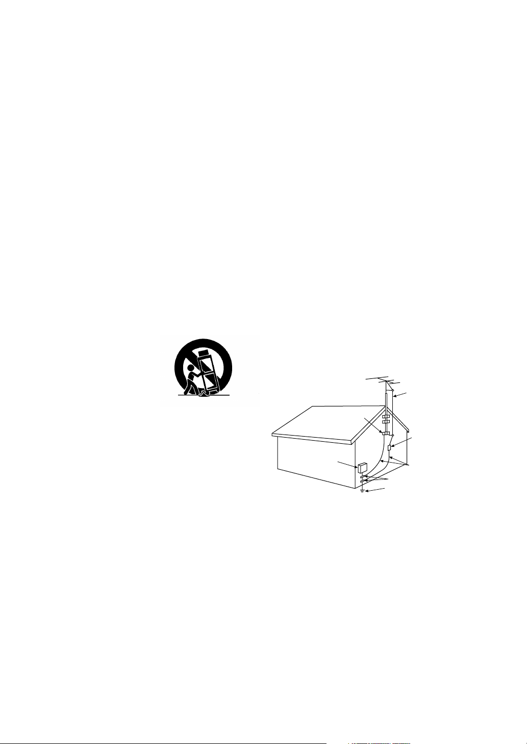
13) Outdoor Antenna Grounding — If an outside antenna or
14) Lightning — For added protection of this video unit
15) Power Lines — An outside antenna system should not
16) Overloading — Do not overload wall outlets and
equipped with either a polarized 2-wire AC (Alternating
Current) line plug (a plug having one blade wider than
the other) or 3-wire grounding type plug, a plug having a
third (grounding) pin.
The 2-wire polarized plug will fit into the power outlet
only one way. This is a safety feature. If you are unable
to insert the plug fully into the outlet, try reversing the
plug. If the plug still fails to fit, contact your electrician to
replace your obsolete outlet. Do not defeat the safety
purpose of the polarized plug.
The 3-wire grounding type plug will fit into a grounding
type power outlet. This is a safety feature. If you are
unable to insert the plug into the outlet, contact your
electrician to replace your obsolete outlet. Do not defeat
the safety purpose of the grounding type plug.
routed so that they are not likely to be walked on or
pinched by items placed upon or against them, paying
particular attention to cords of plugs, convenience
receptacles, and the point where they exit from the unit.
cable system is connected to the video unit, be sure the
antenna or cable system is grounded so as to provide
some protection against voltage surges and built-up
static charges. Part 1 of the Canadian Electrical Code, in
USA Section 810 of the National Electrical Code,
provides information with respect to proper grounding of
the mast and supporting structure, grounding of the lead
in wire to an antenna discharge unit, size of grounding
conductors, location of antenna discharge unit,
connection to grounding electrodes, and requirements
for the grounding electrode.
ANTENNA
LEAD IN
WIRE
GROUND
CLAMP
ANTENNA
DISCHARGE UNIT
ELECTRIC
SERVICE
EQUIPMENT
NEC - NATIONAL ELECTRICAL CODE
(NEC SECTION 810 - 20)
GROUNDING CONDUCTORS
(NEC SECTION 810 - 21)
GROUND CLAMPS
POWER SERVICE GROUNDING
ELECTRODE SYSTEM
(NEC ART 250, PARTH)
receiver during a lightning storm, or when it is left
unattended and unused for long periods of time, unplug
it from the wall outlet and disconnect the antenna or
cable system. This will prevent damage to the video unit
that may be caused by lightning and power-line surges.
be located in the vicinity of overhead power lines or other
electric light or power circuits, or where it can fall into
such power lines or circuits. When installing an outside
antenna system, extreme care should be taken to keep
from touching such power lines or circuits as contact with
them might be fatal.
extension cords as this can result in a risk of fire or
electric shock.

Important Safeguards
17) Objects and Liquids — Never push objects of any kind
into this video unit through openings as they may touch
dangerous voltage points or short out parts that could
result in a fire or electric shock. Never spill liquid of any
kind onto the video unit.
18) Servicing — Do not attempt to service this video unit
yourself as opening or removing covers may expose you
to dangerous voltage or other hazards. Refer all
servicing to qualified service personnel.
19) Damage Requiring Service — Unplug this video unit
from the wall outlet and refer servicing to qualified
service personnel under the following conditions:
a. When the power-supply cord or plug is damaged.
b. If any liquid has been spilled into, or objects have
fallen onto, the video unit.
c. If the video unit has been exposed to rain or water.
d. If the video unit does not operate normally by following
the operating instructions. Adjust only those controls
that are covered by the operating instructions, as an
improper adjustment of other controls may result in
damage and will often require extensive work by a
qualified technician to restore the video unit to its
normal operation.
e. If the video unit has been dropped or the cabinet has
been damaged.
f. When the video unit exhibits a distinct change in
performance — this indicates a need for service.
20) Replacement Parts — When replacement parts are
required, be sure the service technician has used
replacement parts specified by the manufacturer or have
the same characteristics as the original part.
Unauthorized substitutions may result in fire, electric
shock or other hazards.
21) Safety Check — Upon completion of any service or
repairs to this video unit, ask the service technician to
perform safety checks to determine that the video unit is
in safe operating order.
Precautions
USE & LOCATION
≥TO AVOID SHOCK HAZARD... Your Camera/Recorder
and power supply should not be exposed to rain or
moisture. Do not connect the power supply or operate your
Camera/Recorder if it gets wet. Your Camera/Recorder
has been designed for outdoor use, however it is not
designed to sustain direct exposure to water, rain, sleet,
snow, sand, dust, or a direct splashing from a pool or even
a cup of coffee. This action could permanently damage the
internal parts of your Camera/Recorder. Do not attempt to
disassemble this unit. There are no user serviceable parts
inside. Unplug your Camera/Recorder from the power
supply before cleaning.
≥DO NOT AIM YOUR CAMERA/RECORDER AT THE SUN
OR OTHER BRIGHT OBJECTS.
≥DO NOT LEAVE THE CAMERA/RECORDER WITH THE
EVF AIMED DIRECTLY AT THE SUN AS THIS MAY
CAUSE DAMAGE TO THE INTERNAL PARTS OF THE
EVF.
≥DO NOT EXPOSE YOUR CAMERA/RECORDER TO
EXTENDED HIGH TEMPERATURE ... Such as, in direct
sunlight, inside a closed car, next to a heater, etc... This
action could permanently damage the internal parts of your
Camera/Recorder.
≥AVOID SUDDEN CHANGES IN TEMPERATURE ... If the
unit is suddenly moved from a cold place to a warm place,
moisture may form on the tape and inside the unit.
≥DO NOT LEAVE YOUR CAMERA/RECORDER OR THE
POWER SUPPLY TURNED ON WHEN NOT IN USE.
≥STORAGE OF YOUR CAMERA/RECORDER ... Store and
handle your Camera/Recorder in a manner that will not
subject it to unnecessary movement (avoid shaking and
striking). Your Camera/Recorder contains a sensitive pickup device which could be damaged by improper handling
or storage.
CARE
≥TO CLEAN YOUR CAMERA/RECORDER... Do not use
strong or abrasive detergents when cleaning your Camera/
Recorder body.
≥TO PROTECT THE LENS... Do not touch the surface of
the lens with your hand. Use a commercial Camera/
Recorder lens solution and lens paper when cleaning the
lens. Improper cleaning can scratch the lens coating.
≥TO PROTECT THE FINISH OF YOUR CAMERA/
RECORDER... Before handling your Camera/Recorder,
make sure your hands and face are free from any chemical
products, such as suntan lotion, as it may damage the
finish.

Contents
Before Use
Standard Accessories ........................................................ 6
Quick Guide ........................................................................ 7
To watch the Playback Picture ........................................... 7
Controls and Components .................................................. 8
Remote Controller ............................................................ 10
Power Supply ................................................................... 12
Charging Time and Available Recording Time ................. 12
Lens Cap and Grip Belt .................................................... 13
Attaching the Shoulder Strap ........................................... 13
Inserting a Cassette ......................................................... 13
Turning on/off the Camera/Recorder and selecting
Modes ........................................................................... 14
Using the Viewfinder ........................................................ 14
Using the LCD Monitor ..................................................... 14
Using the Menu Screen .................................................... 15
List of Menus .................................................................... 16
Setting Date and Time...................................................... 19
Internal Lithium Battery Recharge.................................... 19
LP Mode........................................................................... 19
Audio Recording Mode..................................................... 19
Camera Mode
Recording ......................................................................... 20
PhotoShot Recording on the DV Cassette....................... 21
Zoom In/Out Functions..................................................... 21
Digital Zoom Function ...................................................... 22
Optical Image Stabilizer Function..................................... 22
Fade In/Out Functions...................................................... 22
Backlight Compensation Function.................................... 23
Recording in Special Situations (Program AE)................. 23
Manual Focus Adjustment................................................ 23
Manual Shutter Speed Adjustment................................... 24
Manual Iris Adjustment (F Number) ................................. 24
Recording with a Fixed Brightness (AE Lock Function) ... 24
Recording in Natural Colors (White Balance) ................... 25
Adjusting White Balance Manually ................................... 25
Digital Effect Functions ..................................................... 26
Special Features
Using a Memory Card .......................................................34
Recording on the Memory Card ........................................34
Playing Back Pictures from the Memory Card ..................35
Copying pictures from a Memory Card to a Cassette .......36
Creating a Title .................................................................37
Inserting a Title .................................................................37
Protecting the Pictures on a Memory Card from
Accidental Erasure (File Lock) ......................................38
Deleting the pictures recorded on a Memory Card ........... 38
Formatting a Memory Card ...............................................39
DPOF Setting ....................................................................39
Copying your DV Cassette to an S-VHS or VHS
Cassette (Dubbing) .......................................................41
Copying an S-VHS or VHS Cassette to
your DV Cassette ..........................................................41
Using your Camera/Recorder with Digital Video
Equipment (Dubbing) ....................................................42
Others
Indications .........................................................................43
Warning/Alarm Indications ................................................ 45
Notes & Precautions ......................................................... 46
Caution for Use .................................................................49
Explanation of Terms ........................................................52
Specifications ....................................................................53
Camera/Recorder Accessory System ...............................54
Before Requesting Service ...............................................55
Index .................................................................................57
VCR Mode
Playing Back ..................................................................... 28
Finding a Scene You Want to Play Back .......................... 28
Slow Motion Playback ...................................................... 29
Still Playback/Still Advance Playback ............................... 29
Finding the End of Recording (Blank Search Function) ... 29
Index Search Functions .................................................... 30
Playback Zoom Function .................................................. 31
Playback Digital Effect Functions ..................................... 31
Playing Back on Your TV ................................................. 33
Audio Dubbing .................................................................. 33
1)
2)
3)
VSB0419
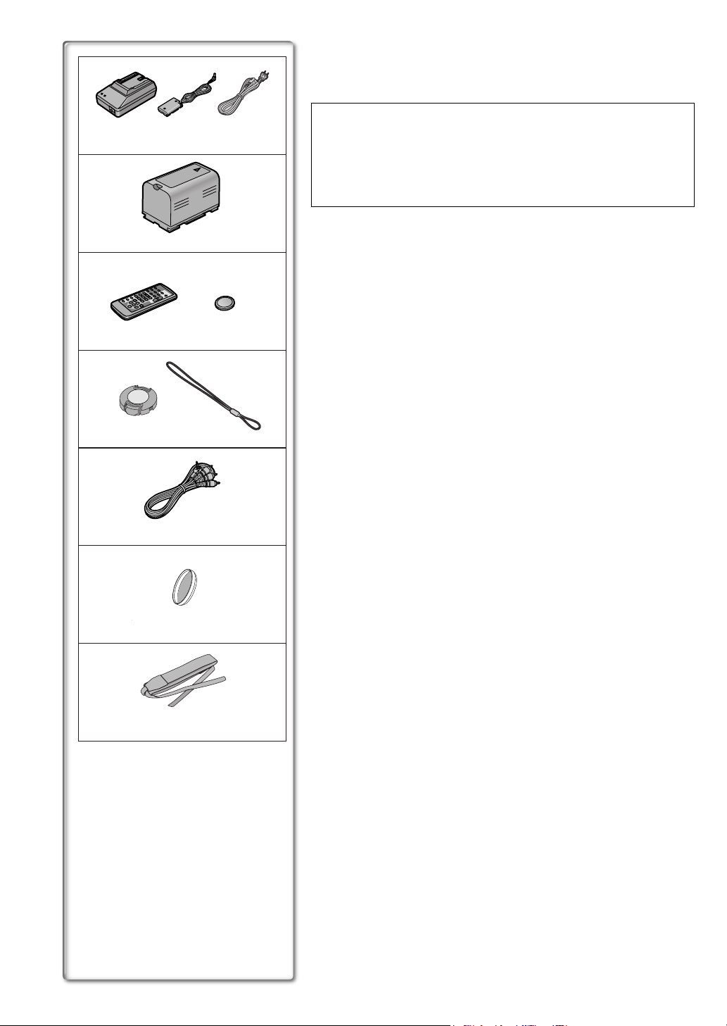
Standard Accessories
Illustrated on the left are accessories packaged with the Camera/Recorder.
1) AC Adaptor, DC Cable and AC Cable (l 12)
≥Supplies power to the Camera/Recorder.
CAUTION:
This unit will operate on 110/120/220/240V AC. An AC plug adaptor may
be required for voltages other than 120V AC. Please contact either a
local or foreign electrical parts distributor for assistance in selecting an
alternate AC plug. We recommend using the accessory power plug
adaptor in an area which has special AC outlets.
2) Battery Pack (l 12)
≥Supplies power to the Camera/Recorder.
3) Remote Controller and Button-Type Battery (l 10, 11)
4) Lens Cap and Lens Cap Cord (l 13)
5) A/V Cable (l 33, 41)
6) ND Filter (l 51)
7) Shoulder Strap (l 13)
N2QAEC000003
4)
VFC3580
5)
K2KC4CB00002
6)
7)
CR2025
VYQ2281
VFC3506
Quick Guide
OPEN / EJECT
2
1
CAMERA
VCR
2
3
1
MODE
ON
OFF
POWER
CARD P.B.
1
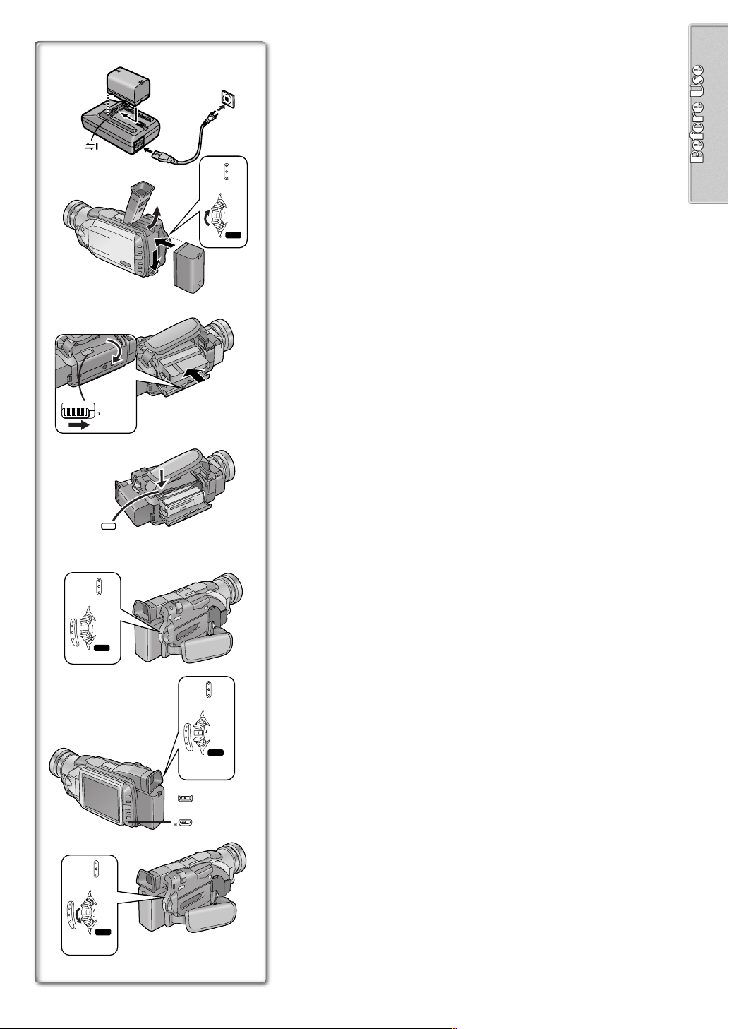
Charge the Battery.
(l 12)
≥Connect the AC Cable to the AC Adaptor and AC Jack.
≥Attach the Battery to the AC Adaptor. (This will start the charging
process.)
≥When the Charge Lamp [CHARGE] goes off, the Battery is fully
charged.
≥Since the Battery will not be charged when the DC Cable is connected
to the AC Adaptor, disconnect it.
2
Attach the Charged Battery to the Camera/Recorder.
≥Attach the battery after tilting the Viewfinder upward.
(l 12)
4
3
Turn the Camera/Recorder on.
≥Slide the
Switch to [ON]. (The [CAMERA] Lamp lights up.)
1
(l 14)
4
3
PUSH
TO CLOSE
CAMERA
VCR
CARD P.B.
MODE
ON
OFF
POWER
4
Insert the Cassette.
≥Slide the
Lever to the right and pull down to open the Cassette
2
(l 13)
compartment cover.
≥Insert the Cassette.
≥Press the [PUSH/TO CLOSE]
to load the Cassette.
3
≥Close the lower compartment Cover.
5
CAMERA
VCR
CARD P.B.
MODE
BACK
LIGHT
SEARCH
7
6
ON
OFF
POWER
5
6
5
Start recording.
≥Press the
≥Press the
(l 20)
Button. (Recording starts.)
4
Button again to pause the recording.
4
To watch the Playback Picture
6
Switch to the VCR Mode, rewind the tape, and play the tape
(l 28)
back.
≥Slide the
≥Press the
≥Press the
Switch. (The [VCR] Lamp lights up.)
5
Button.
6
Button. (This will start playback.)
7
MODE
ON
OFF
POWER
8
CAMERA
VCR
CARD P.B.
7
7
Turn the Camera/Recorder off.
≥Set the 8 Switch to [OFF].
(l 14
)
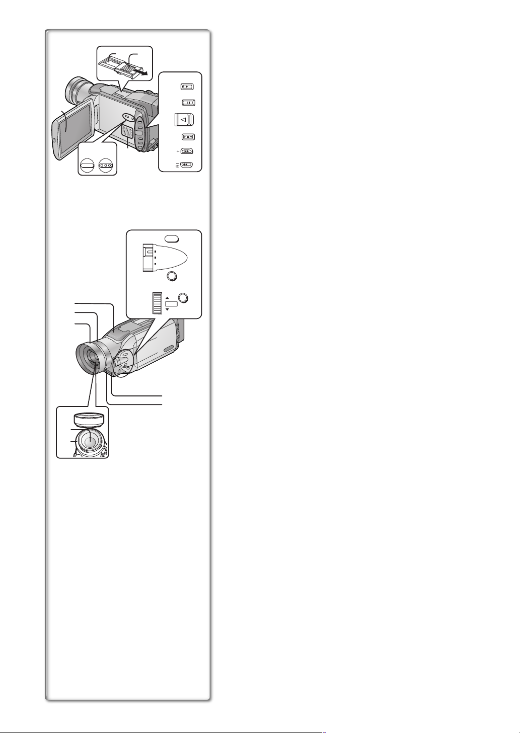
Controls and Components
16)
17)
2) 3)
1) LCD Monitor (l 14, 51)
.........................................................................................................................
BACK
LIGHT
4)
CAMERA
STILL
1)
5)
PUSH OPEN
6)
FADE
7)
10)
11)
TITLE MULTI/P-IN-P
12)
8)
9)
SEARCH
≥Due to limitations in LCD production technology, there may be some
tiny bright or dark spots on the LCD Monitor screen. However, this is
not a malfunction and does not affect the recorded picture.
.........................................................................................................................
2) Accessory Shoe
≥Accessories, such as a stereo microphone (not supplied), are attached
here.
3) Shoe Cover
4) Backlight Button [BACK LIGHT] (l 23)
Play Button [1] (l 28, 29, 35)
5) Still Button [CAMERA STILL] (l 21)
Pause Button [;] (l 29, 35)
6) LCD Monitor Open Lever [PUSH OPEN] (l 14)
7) Fade Button [FADE] (l 22)
Stop Button [∫] (l 28, 29, 35)
8) Forward Search Button [rSEARCH] (l 20)
(l 28)
Fast Forward/Cue Button [5]
9) Reverse Search Button [sSEARCH] (l 20)
Rewind/Review Button [6] (l 28)
Recording Check Button [S] (l 20)
10) Title Button [TITLE] (l 37)
11) Multi-Picture Button [MULTI] (l 27, 32, 36, 37)
13)
14)
15)
21)
SHUTTER/IRIS
24)
20)
22)
AUTO
MANUAL
AE LOCK
PUSH
VOL/JOG
FOCUS
W.B .
23)
MENU
Picture-in-Picture Button [P-IN-P] (l 27)
12) Speaker
13) Microphone (built-in, stereo)
14) Focus Ring (l 23)
18)
19)
15) Lens Hood
≥Always keep the Lens Hood attached to the Camera/Recorder so as to
shut out unnecessary light.
16) Lens (LEICA DICOMAR)
≥LEICA is a registered trademark of Leica microsystems IR GmbH and
DICOMAR is a registered trademark of Leica Camera AG.
17) MC Protector (l 51)
18) Remote Control Sensor (l 11)
19) Tally Lamp (l 20)
20) Focus Button [FOCUS] (l 23)
21) Mode Selector Switch [AUTO/MANUAL/AE LOCK]
(l 20, 23, 24, 25)
22) White Balance Button [W.B.] (l 25)
23) Menu Button [MENU] (l 15)
24) Multi-Function Dial [PUSH] (l 15, 19, 28, 29)
25)
26)
27)
28)
29)
30)
31)
41)
42)
43)
44)
45)
TAPE CARD
32)
48)
49) 50)
AV IN/OUT
AUX
PHONES
S-VIDEO IN/OUT
MIC
51) 52)
53)
47)
33)
34)
35)
36)
37)
38)
39)
40)
46)
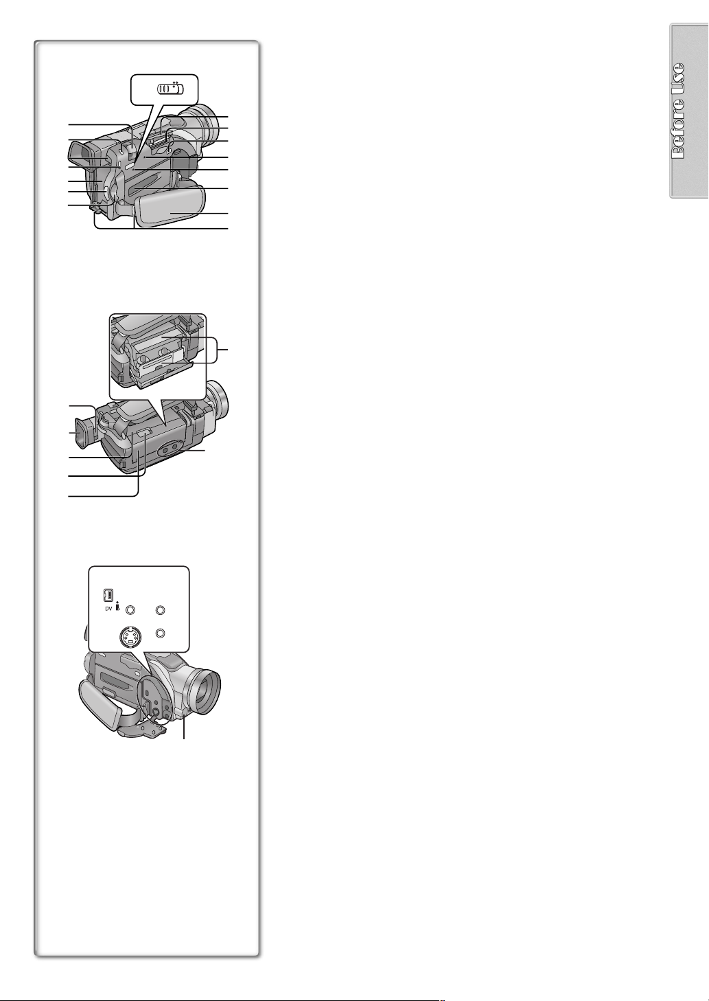
25) Zoom Lever [W/T] (l 21, 22)
26) Photoshot Button [PHOTO SHOT] (l 21, 34)
27) Battery Eject Button [BATT. EJECT] (l 12)
28) Operation Mode Lamps [CAMERA/VCR/CARD P.B.] (l 14, 20, 28, 35)
29) Battery Holder (l 12)
30) Recording Start/Stop Button (l 20)
31) Power Off/On Mode Selector Switch [OFF/ON/MODE] (l 14)
32) Tape/Card Photoshot Selector [TAPE/CARD] (l 21, 34)
33) Card Slot Cover (l 34)
34) Card Slot (l 34)
35) Card Slot Cover Open Lever [OPEN] (l 34)
36) Card Access Lamp [ACCESS] (l 34)
37) Reset Button [RESET] (l 55)
38) Cassette Compartment Window (l 13)
39) Grip Belt (l 13)
40) Shoulder Strap Holders (l 13)
41) Eyepiece Corrector Knob (l 14)
42) Viewfinder (l 14, 51)
.........................................................................................................................
≥Due to limitations in LCD production technology, there may be some
tiny bright or dark spots on the Viewfinder screen. However, this is not
a malfunction and does not affect the recorded picture.
.........................................................................................................................
43) Upper Cassette Compartment Cover (l 13)
44) Cassette Eject Lever [OPEN/EJECT] (l 13)
45) Lower Cassette Compartment Cover (l 13)
46) Cassette Holder (l 13)
47) Tripod Receptacle (Tripod Mounting Hole)
≥Used for mounting the Camera/Recorder on an optional tripod.
48) DV Input/Output Terminal (i.LINK) [¥] (l 42)
≥Connect this to the digital video equipment.
49) Auxiliary Terminal [AUX]
50) Audio-Video Input/Output Jack [AV IN/OUT] (l 33, 41)
Headphone Jack [PHONES]
(l 48)
≥When a cable is connected to this jack, the built-in speaker of the
Camera/Recorder is disabled.
51) S-Video Input/Output Jack [S-VIDEO IN/OUT] (l 33, 41)
52) Microphone Jack [MIC] (l 33, 48)
≥Connect with an external microphone or audio equipment. (When this
jack is in use, the built-in microphone does not function.)
53) White Balance Sensor (l 25, 52)
11)
12)
13)
14)
15)
26)
27)
28)
29)
30)
1)
2)
3)
4)
5)
VIDEO CAMERA
START/
PHOTO
DATE/
OSD
TIME
COUNTER
RESET
MULTI/
¥REC
P-IN-P
V
/REW
PLAY
61 5
STILL ADV
PAUSE
;
ED
STOP
INDEX INDEX
KL
∫
SELECT
VAR.
SEARCH
STORE
OFF/ON
P.B.DIGITAL
DATE/
OSD
TIME
COUNTER
RESET
MULTI/
¥REC
P-IN-P
V
/REW
PLAY
61 5
STILL ADV
PAUSE
;
ED
STOP
INDEX INDEX
KL
∫
SELECT
VAR.
SEARCH
STORE
OFF/ON
P.B.DIGITAL
DATE/
OSD
TIME
COUNTER
RESET
MULTI/
¥REC
P-IN-P
V
/REW
PLAY
61 5
STILL ADV
PAUSE
;
ED
STOP
INDEX INDEX
KL
∫
SELECT
VAR.
SEARCH
STORE
OFF/ON
P.B.DIGITAL
SHOT
TITLE
A.DUB
FF/
STILL ADV
MENU
PHOTO
SHOT
TITLE
A.DUB
FF/
STILL ADV
MENU
PHOTO
SHOT
TITLE
A.DUB
FF/
STILL ADV
MENU
STOP
ZOOM
sVOLr
W
P.B.
ZOOM
ITEM
VIDEO CAMERA
START/
STOP
ZOOM
sVOLr
W
W
P.B.
ZOOM
ITEM
VIDEO CAMERA
START/
STOP
ZOOM
sVOLr
W
W
P.B.
ZOOM
ITEM
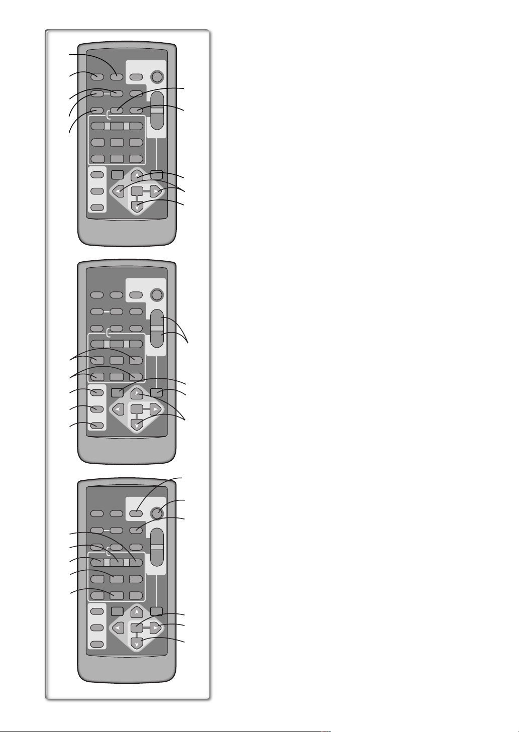
Remote Controller
Using the wireless remote controller that is supplied with the Camera/
Recorder, most of the Camera/Recorder functions can be operated from a
distance.
T
6)
7)
W
8)
9)
SET
10)
T
16)
17)
18)
SET
19)
20)
21)
22)
T
23)
24)
SET
25)
Remote Controller Buttons
1) Date and Time Button [DATE/TIME] (l 45)
2) Indication Output Button [OSD] (On-Screen Display) (l 33)
3) Counter Reset Button [RESET] (l 52)
4) Indication Shift Button [COUNTER] (l 45)
5) Multi-Picture/Picture-in-Picture Button [MULTI/P-IN-P]
(l 27, 32, 36, 37)
6) Recording Button [REC] (l 41, 42)
7) Audio Dubbing Button [A.DUB] (l 33)
8) Upward Direction Button [π] (for Playback Zoom Function) (l 31)
9) Left/Right Direction Buttons [∑, ∏] (for Playback Zoom Function)
(l 31)
10) Downward Direction Button [∫] (for Playback Zoom Function)
(l 31)
11) Slow Motion/Still Advance Buttons [EEEE, DDDD]
(E
E : reverse direction, DDDD: normal direction) (l 29)
E E
12) Index Search Buttons [::::, 9999]
(::::: reverse direction, 9
9: normal direction) (l 30)
9 9
13) Selection Button [SELECT] (l 31)
14) Store Button [STORE] (l 31)
15) Off/On Button [OFF/ON] (l 31)
16) Zoom/Volume Button [ZOOM/VOL] (l 21, 22, 28, 31)
17) Variable Speed Search Button [VAR.SEARCH] (l 28)
18) Playback Zoom Button [P.B. ZOOM] (l 31)
19) Speed Selection Buttons [π, ∫] (for variable speed search function)
(l 28)
The following buttons function in the same manner as the corresponding
buttons on the Camera/Recorder.
20) Photoshot Button [PHOTO SHOT] (l 21, 34)
21) Recording Start/Stop Button [START/STOP] (l 20)
22) Title Button [TITLE] (l 37)
23) Menu Button [MENU] (l 15)
24) Item set Button [SET] (l 15)
25) Item select Button [ITEM] (l 15)
26) Fast-forward/Cue Button [5555] (l 28)
27) Play Button [1111] (l 28, 29, 35)
28) Rewind/Review Button [6] (l 28)
29) Pause Button [;;;;] (l 29, 35)
30) Stop Button [∫∫∫∫] (l 28, 29, 35)
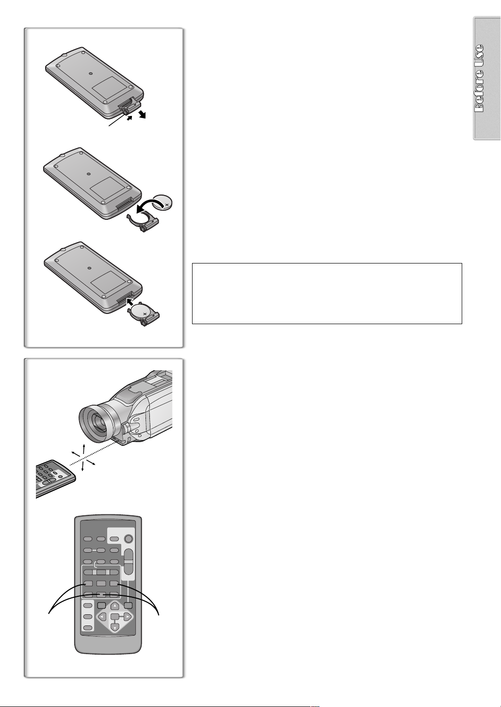
ª Inserting a Button-type Battery
Before using the remote controller, insert the supplied button-type battery.
1
1
1
2
3
While pressing the Stopper 1, pull out the Battery Holder.
Insert the button-type battery with the imprint (i) facing
2
upward.
Insert the Battery Holder into the Remote Controller.
3
≥When the button-type battery becomes weak, replace it with a new CR2025
battery. (A battery is normally expected to last about one year. However, it
depends on operation frequency.)
≥Make sure to match the poles properly when inserting the battery.
.........................................................................................................................
Warning
Danger of explosion if battery is incorrectly replaced.
Replace only with the same or equivalent type recommended by the
equipment manufacturer. Discard used batteries according to
manufacturer’s instructions.
Risk of fire, explosion and burns. Do not recharge, disassemble, heat
above 212°F (100°C) or incinerate. Keep the Button-Type battery out of
the reach of children. Never put Button-Type battery in mouth. If
swallowed call your doctor.
.........................................................................................................................
Replace battery with CR2025 only. Use of another battery may present a
risk of fire or explosion.
Caution-Battery may explode if mistreated.
Dispose of used battery promptly. Keep away from children. Do not
recharge, disassemble or dispose of in fire.
~~~~~~~~~~~~~~~~~~~~~~~~~~~~~~~~
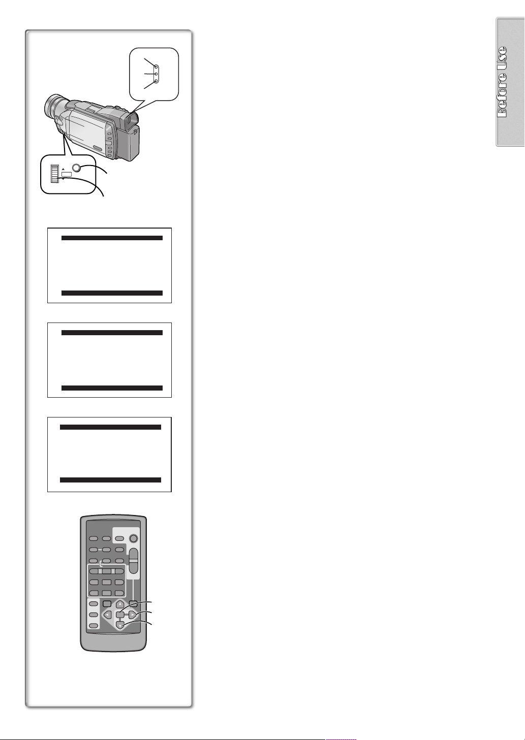
ª Using the Remote Controller
1
Direct the Remote Controller to the Remote Control Sensor
on the Camera/Recorder and press the desired button.
≥Distance from the Camera/Recorder: Within Approximately 15 feet
(5 meters)
≥Angle: Approximately 15 degrees in the vertical and horizontal
directions from the central axis
1
≥The above operating ranges are for indoor use. Outdoors or under strong
light, the equipment may not operate properly even within the above
ranges.
≥Within 3 feet (1 meter) range, you can also use the Remote Controller on
the side (the LCD Monitor side) of the Camera/Recorder.
Selecting Remote Controller Modes
When 2 Camera/Recorders are used simultaneously, they can be operated
VIDEO CAMERA
START/
PHOTO
DATE/
TIME
RESET
¥REC
PLAY
PAUSE
STOP
SEARCH
STOP
SHOT
TITLE
ZOOM
T
A.DUB
sVOLr
W
FF/
W
STILL ADV
;
∫
VAR.
P.B .
ZOOM
MENU
SET
ITEM
OSD
COUNTER
MULTI/
P-IN-P
V
/REW
615
STILL ADV
ED
INDEX INDEX
KL
SELECT
21
STORE
OFF/ON
P.B.DIGITAL
individually by selecting different Remote Controller Modes.
≥If the Remote Controller Mode on the Camera/Recorder and Remote
Controller do not match, [REMOTE] is displayed.
Setting on the Camera/Recorder:
Set [REMOTE] on the [OTHER FUNCTIONS] Sub-Menu to the desired
Remote Controller Mode.
Setting on the Remote Controller:
[VCR1]: Press the [D] Button and [∫] Button simultaneously.
[VCR2]: Press the [E] Button and [∫] Button simultaneously.
≥When the battery in the Remote Controller is replaced, the Mode is
automatically reset to [VCR1] Mode.
1
2
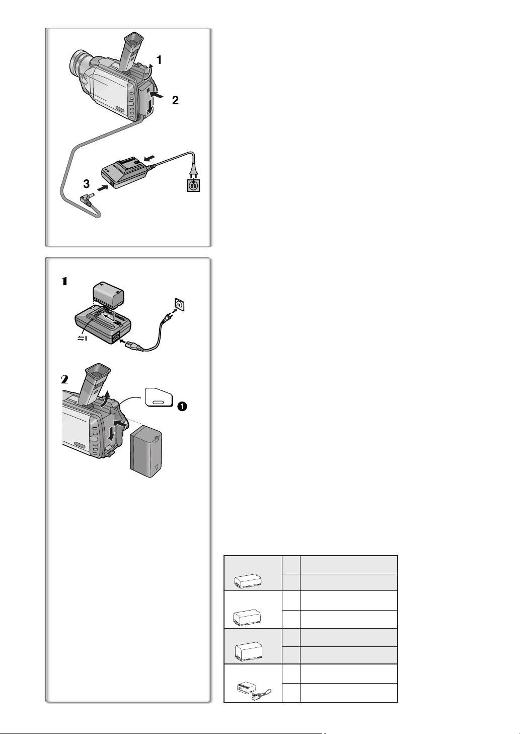
Power Supply
ª Using the AC Adaptor
1
2
1
Slide the Viewfinder backward and then tilt it upward.
Insert the battery-shaped connector of the DC Cable into the
2
Battery Holder on the Camera/Recorder.
Connect the DC connector plug to the [DC OUT] Jack on the
3
AC Adaptor.
Connect the AC Adaptor and AC Cable.
4
4
3
~~~~~~~~~~~~~~~~~~~~~~~~~~~~~~~~
ª Using the Battery
1
≥Before use, fully charge the battery.
1 Attach the Battery to the AC Adaptor and charge it.
≥Since the Battery will not be charged when the DC Cable is connected
to the AC Adaptor, disconnect it.
≥The [CHARGE] Lamp lights up, and charging starts.
≥When the [CHARGE] Lamp goes off, charging is completed.
2 Attach the charged Battery to the Camera/Recorder.
Disconnecting the Power Source
Set the [OFF/ON/MODE] Switch to [OFF] and, while pressing the
2
BATT.
EJECT
PUSH
1
[BATT. EJECT] Button
disconnect it.
≥For other notes, see page 46.
~~~~~~~~~~~~~~~~~~~~~~~~~~~~~~~~
, slide the Battery or DC Cable upward to
1
Charging Time and Available Recording Time
A
Charging Time
B Maximum Continuous Recording Time
≥“1 h 20 min.” indicates 1 hour and 20 minutes.
≥Battery VSB0419 is supplied.
≥The hours shown in the table below are approximate hours. The numeric
characters in parentheses indicate the recording time when the LCD
monitor is used. In actual use, the available recording time may be shorter
in some cases.
≥The hours shown in the table below are for continuous recording at a
temperature of 68xF (20xC) and humidity of 60 %. If the Battery is charged
at a higher or lower temperature, the charging time may become longer.
CGR-D08A/1B
VSB0419
CGR-D16A/1B
CGP-D28A/1B
CGR-D53A/1K
A
1 h.
B
1 h 10 min. (55 min.)
A
2 h.
B
2 h 25 min. (2 h.)
A
3 h 15 min.
B
4 h 15 min. (3 h 35 min.)
5 h 20 min.
A
B
8 h. (6 h 40 min.)
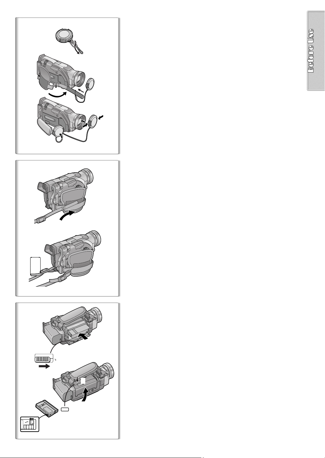
Lens Cap and Grip Belt
1
To protect the Lens surface, attach the Lens Cap. Adjust the length of the
Grip Belt to the size of your hand.
Attach the longer loop of the Lens Cap Cord to the Lens
1
Cap.
Attach the shorter loop to the Grip Belt.
2
Put your hand through the Grip Belt and adjust the length.
3
≥The removed Lens Cap can be hooked onto the Grip Belt 1. (When you
are not recording, be sure to keep the Lens Cap attached to the Lens for
protection.)
1
2
2
1
3
2
~~~~~~~~~~~~~~~~~~~~~~~~~~~~~~~~
Attaching the Shoulder Strap
We recommend that you attach the Shoulder Strap before going outdoors to
record so as to avoid dropping the Camera/Recorder.
Pass the tip of the Shoulder Strap through the Shoulder
1
Strap Holder on the Camera/Recorder and pull the Shoulder
Strap.
Fold the tip of the Shoulder Strap, pass it through the
2
Shoulder Strap Length Adjuster, and pull it.
≥Pull it out more than 1 inch (2 cm) 2 from the Shoulder Strap Length
Adjuster so that it cannot slip off.
~~~~~~~~~~~~~~~~~~~~~~~~~~~~~~~~
Inserting a Cassette
When power is supplied to the Camera/Recorder, the cassette can be taken
2
3
1
OPEN / EJECT
3
4
4
R E C
SAVE
PUSH
TO CLOSE
out without turning the Camera/Recorder on.
Slide the [OPEN/EJECT] Lever 3 to the right and pull down
1
to open the Cassette Compartment.
Insert a Cassette.
2
Close the Cassette Compartment and lock the Cassette
3
Compartment by pressing the [PUSH TO CLOSE] mark.
Close the Lower Cassette Compartment Cover.
4
≥For other notes, see page 46.
ª Accidental Erasure Prevention
Opening the accidental erasure prevention slider 4 on the cassette (by
sliding it in the [SAVE] arrow direction) prevents recording. To enable
recording, close the accidental erasure protection slider (by sliding it in the
[REC] arrow direction).
1
2:51:32PM
2:51:32PM
OCT 1 2001
1
PUSH
1, 2
VOL/JOG
2
3
LCD/EVF SET
LCD BRIGHTNESS
LOW ||||---- HIGH
LCD COLOR
LOW ||||---- HIGH
EVF BRIGHTNESS
LOW ||||---- HIGH
PUSH MENU TO RETURN
CAMERA
VCR
CARD P.B.
1, 2, 3
MODE
ON
OFF
32
2:51:32PM
OCT 1 2001
2
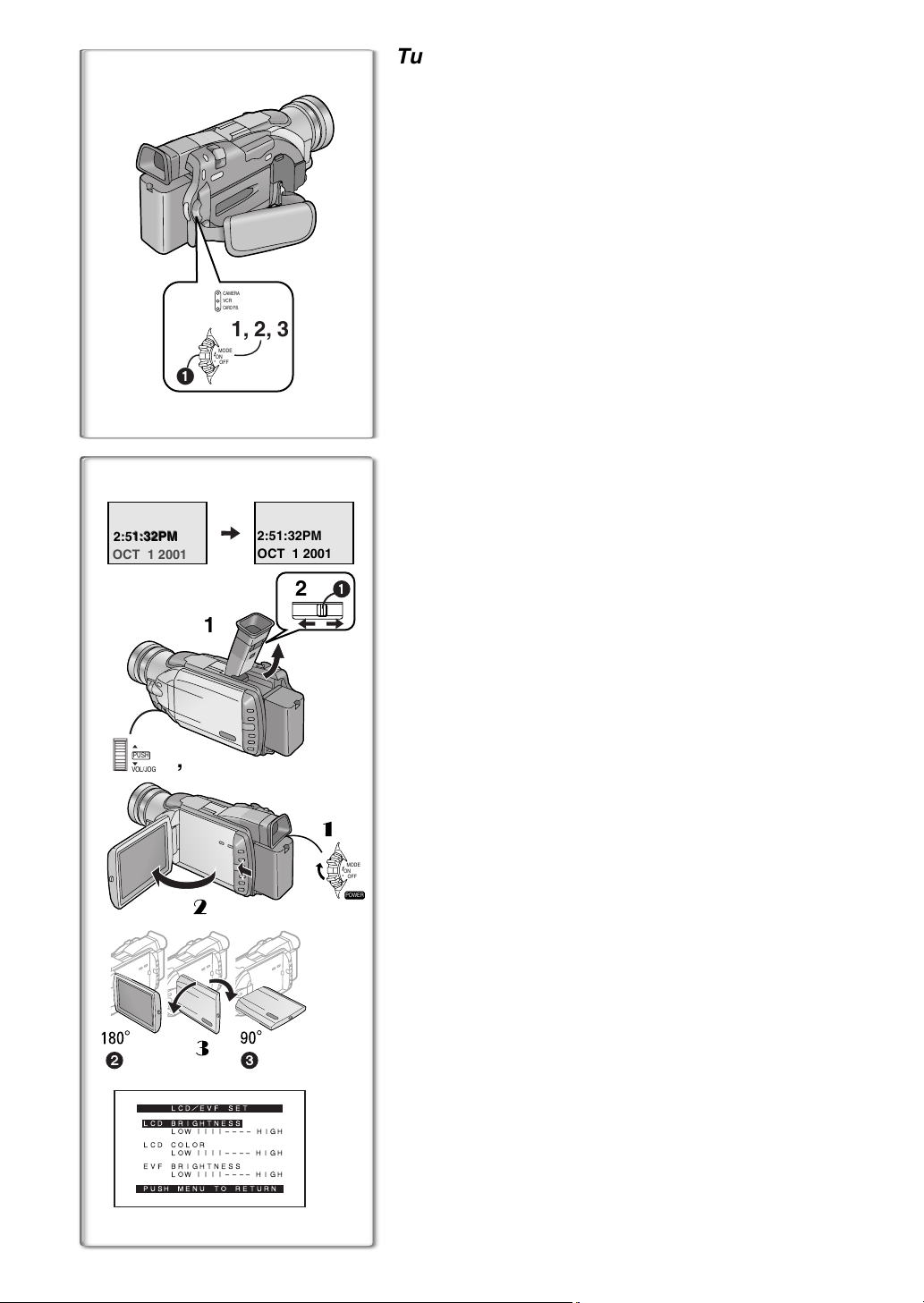
Turning on/off the Camera/Recorder and
selecting Modes
Turn on the power first and then select Modes.
ª How to Turn on the Power
1
Set the [OFF/ON/MODE] Switch to [ON] while pressing the
center Button
≥The [CAMERA] Lamp lights up.
1
.
ª How to Switch Modes
2
Slide the [OFF/ON/MODE] Switch.
≥With each slide of the Switch, the Mode switches in the order of Camera
Mode, VCR Mode, and Card Playback Mode.
≥The appropriate Mode Lamp lights up.
ª How to Turn off the Power
3
Set the [OFF/ON/MODE] Switch to [OFF] while pressing the
center Button
1
.
~~~~~~~~~~~~~~~~~~~~~~~~~~~~~~~~
Using the Viewfinder
Before using the Viewfinder, adjust the field of view so that the displays inside
the Viewfinder become clear and easy to read.
Slide the Viewfinder backward and then tilt it upward.
1
≥The Viewfinder angle is adjusted upward.
Adjust by sliding the Eyepiece Corrector Knob 1.
2
1
1
Using the LCD Monitor
With the LCD Monitor open, you can also record the picture while watching it.
1 Turn the [OFF/ON/MODE] Switch to [ON].
2 Slide the [PUSH OPEN] Lever and, at the same time, bring
x
out the LCD Monitor about 90
≥The Viewfinder goes off.
3 Adjust the LCD Monitor angle according to the desired
recording angle.
≥The LCD Monitor can rotate a maximum of 180x 2 from the vertical
position to the upward direction and a maximum of 90x
downward direction. Forcefully rotating the LCD monitor beyond these
ranges will damage the Camera/Recorder.
Closing the LCD monitor
Push the LCD Monitor until the [PUSH OPEN] Lever is securely locked.
MODE
ON
OFF
ª Adjusting Brightness and Color Level
POWER
When [LCD/EVF SET] on the [DISPLAY SETUP] Sub-menu is set to [YES],
the following items are displayed. (l 15)
LCD Brightness [LCD BRIGHTNESS]
Adjusts the brightness of the image on the LCD screen.
LCD Color Level [LCD COLOR]
Adjusts the color saturation of the image on the LCD screen.
Brightness of the Viewfinder [EVF BRIGHTNESS]
Adjust the brightness of the image in the Viewfinder.
Press the [PUSH] Dial and select the item you want to adjust.
1
Rotate the [PUSH] Dial and increase or decrease the number
2
of the vertical bars on the Bar Indication.
≥The Bar Indication has 8 steps. A larger number of vertical bars
indicates stronger brightness or color saturation.
Increasing the Brightness of the Entire LCD Monitor
Set the [LCD MODE] on the [DISPLAY SETUP] Sub-Menu to [BRIGHT].
≥These adjustments do not affect the recorded images.
in the direction of the arrow.
3
to the
MENU
PUSH
VOL/JOG
1
2, 3, 4, 5
1
CAMERA FUNCTIONS
1.
CAMERA SETUP
2.
DIGITAL EFFECT
3.
CARD SETUP
4.
MULTI-PICTURES
5.
RECORDING SETUP
6.
DISPLAY SETUP
7.
OTHER FUNCTIONS
PUSH MENU TO EXIT
2
VCR FUNCTIONS
1.
PLAYBACK FUNCTIONS
2.
DIGITAL EFFECT
3.
CARD SETUP
4.
MULTI-PICTURES
5.
RECORDING SETUP
6.
AV IN/OUT SETUP
7.
DISPLAY SETUP
8.
OTHER FUNCTIONS
PUSH MENU TO EXIT
3
CARD FUNCTIONS
1.
DELETE PICTURE/TITLE
2.
CARD EDITING
3.
DISPLAY SETUP
4.
OTHER FUNCTIONS
1
2
3
CAMERA
VCR
CARD P.B.
Using the Menu Screen
To facilitate the selection of a desired function or setting, this Camera/
Recorder displays various function settings on menus.
Press the [MENU] Button.
1
≥When the [CAMERA] Lamp is on, the Camera Function Menu is
displayed.
≥When the [VCR] Lamp is on, the VCR Function Menu is displayed.
≥When the [CARD P.B.] Lamp is on, the Card Function Menu is
displayed.
Rotate the [PUSH] Dial to select a desired Sub-Menu.
2
≥Rotate the [PUSH] dial to display the items highlighted.
Press the [PUSH] Dial to display the selected Sub-Menu.
3
Rotate the [PUSH] Dial to select the item to be set.
4
Press the [PUSH] Dial to set the selected item to a desired
5
Mode.
≥Each press of the cursor [1] brings up a subsequent Mode. Menu items
that cannot be used in combination with the selected item are displayed
in dark blue.
≥While a Menu is displayed, you cannot record or play back. Menus can be
displayed during playback but not during recording.
≥The above operations can be carried out using the Remote Controller.
(l 10)
≥To display the Menu, press the [MENU] Button
Controller.
≥To select items on the Menu, press the [ITEM] Button
Remote Controller.
≥To set the mode for the selected items, press the [SET] Button
the Remote Controller.
To Exit the Menu Screen
Press the [MENU] Button again.
About the Menu Mode Setting
The setting selected on the Menu will be retained even when the Camera/
Recorder is turned off. However, if the Battery or AC Adaptor is disconnected
before turning the Camera/Recorder off, the selected setting may not be
retained.
1
3
on the Remote
4
on the
5
6
2
on
PUSH MENU TO EXIT
VIDEO CAMERA
START/
PHOTO
DATE/
TIME
RESET
¥REC
PLAY
PAUSE
STOP
SEARCH
STOP
SHOT
TITLE
ZOOM
T
A.DUB
sVOLr
W
FF/
W
STILL ADV
;
∫
VAR.
P.B.
ZOOM
MENU
SET
ITEM
OSD
COUNTER
MULTI/
P-IN-P
V
/REW
615
STILL ADV
ED
INDEX INDEX
KL
SELECT
STORE
OFF/ON
P.B.DIGITAL
4
6
5
1)
PROG.AE OFF 5 7
2)
PROGRESSIVE AUTO ON OFF
3)
EIS
D.ZOOM
4)
REC MODE
5)
RETURN ---- YES
6)
EFFECT1
7)
EFFECT2 OFF NEGA SEPIA
8)
RETURN ---- YES
9)
PICTURE SIZE
REC MODE
10)
FINE NORMAL ECONOMY
LOW LIGHT SHOT
11)
CREATE TITLE
12)
RETURN ---- YES
13)
SCAN MODE
14)
SPEED FAST NORMAL SLOW
SWING OFF ON
15)
P-IN-P 1 2 3 4
16)
RETURN ---- YES
17)
REC-SPEED
18)
AUDIO-REC 12bit
INDEX 2HOUR DAY
WIND-CUT OFF ON
19)
CAMERA SETUP
N Ω º
OFF ON
OFF 25 100
NORMAL FRAME
PUSH MENU TO EXIT
DIGITAL EFFECT
OFF MULTI P-IN-P
WIPE MIX STROBE
GAIN-UP TRAIL
MOSAIC MIRROR
MONO SOLARI
PUSH MENU TO EXIT
CARD SETUP
PUSH MENU TO EXIT
MULTI-PICTURES
STROBE MANUAL
PUSH MENU TO EXIT
RECORDING SETUP
SP LP
20)
RETURN ---- YES
PUSH
MENU TO EXIT
21)
22)
23)
24)
25)
26)
27)
28)
29)
30)
31)
32)
DISPLAY SETUP
DATE/TIME
C.DISPLAY LINEAR MEMORY
C.RESET ---- YES
DISPLAY ALL PARTIAL OFF
LCD MODE NORMAL BRIGHT
LCD/EVF SET
RETURN ---- YES
REMOTE
TALLY LED OFF ON
BEEP OFF ON
SHUTTER OFF ON
CLOCK-SET ---- YES
SELF-REC NORMAL MIRROR
RETURN ---- YES
OFF D/T DATE
T.CODE
PUSH MENU TO EXIT
OTHER FUNCTIONS
VCR1 VCR2 OFF
PUSH MENU TO EXIT
1488 1128 640 480
OFF AUTO
---- YES
16bit
---- YES
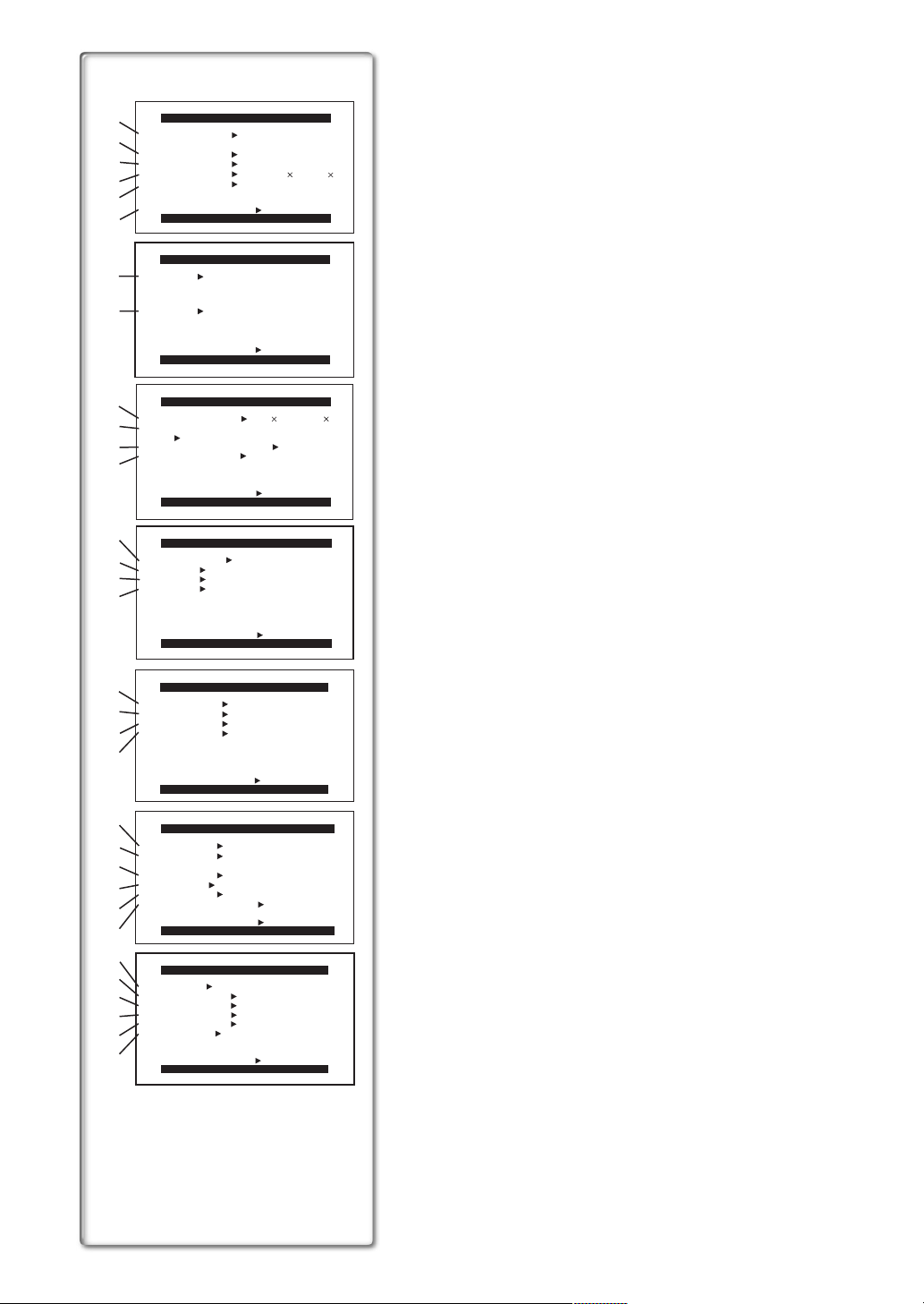
List of Menus
The illustrations of the Menus are for explanation purposes only, and they are
different from the actual Menus.
Camera Mode Main-Menu [CAMERA FUNCTIONS]
[CAMERA SETUP] Sub-Menu
1) Auto Exposure Mode [PROG.AE] (l 23)
2) Progressive Photoshot Mode [PROGRESSIVE] (l 21)
3) Optical Image Stabilizer [EIS] (l 22)
4) Digital Zoom [D.ZOOM] (l 22)
5) Recording Mode [REC MODE] (l 21)
6) Returning to the Main-Menu [RETURN]
[DIGITAL EFFECT] Sub-Menu
7) Digital Effects 1 [EFFECT1] (l 26)
8) Digital Effects 2 [EFFECT2] (l 26)
[CARD SETUP] Sub-Menu
9) Picture Size [PICTURE SIZE] (l 34)
10) Picture Quality [REC MODE] (l 34)
11) Card Low Brightness [LOW LIGHT SHOT] (l 34)
12) Title Creation [CREATE TITLE] (l 37)
[MULTI-PICTURES] Sub-Menu
13) Multi-Picture Mode [SCAN MODE] (l 27)
14) Strobe Multi-Picture Speed [SPEED] (l 27)
15) Swing Mode [SWING] (l 27)
16) Position of Small Picture inside Normal Picture [P-IN-P] (l 27)
[RECORDING SETUP] Sub-Menu
17) Recording Speed Mode [REC-SPEED] (l 19)
18) Audio Recording Mode [AUDIO-REC] (l 19, 33)
19) Index Mode [INDEX] (l 30)
20) Wind Noise Reduction [WIND-CUT]
≥If this function is set to [ON], the sound of wind hitting the microphone
can be reduced for recording.
[DISPLAY SETUP] Sub-Menu
21) Date and Time Indication [DATE/TIME] (l 45)
22) Counter Display Mode [C.DISPLAY] (l 45)
23) Counter Reset [C.RESET] (l 52)
≥Set the counter value to zero. However, it cannot reset the Time Code.
24) Display Mode [DISPLAY] (l 45)
25) LCD Brightness [LCD MODE] (l 14)
26) LCD and Viewfinder Adjustment [LCD/EVF SET] (l 14)
[OTHER FUNCTIONS] Sub-Menu
27) Remote Controller Mode [REMOTE] (l 11)
28) Recording Lamp [TALLY LED] (l 20)
29) Beep Sound [BEEP]
1 Beep
≥When you start recording
≥When you switch the [OFF/ON/MODE] Switch from [OFF] to [ON]
2 Beeps
≥When you pause recording
10 Beeps
≥If you perform a wrong operation before or during recording
30) Shutter Sound Effect [SHUTTER] (l 21)
31) Date and Time Setting [CLOCK-SET] (l 19)
32) Self-Recording [SELF-REC] (l 20)
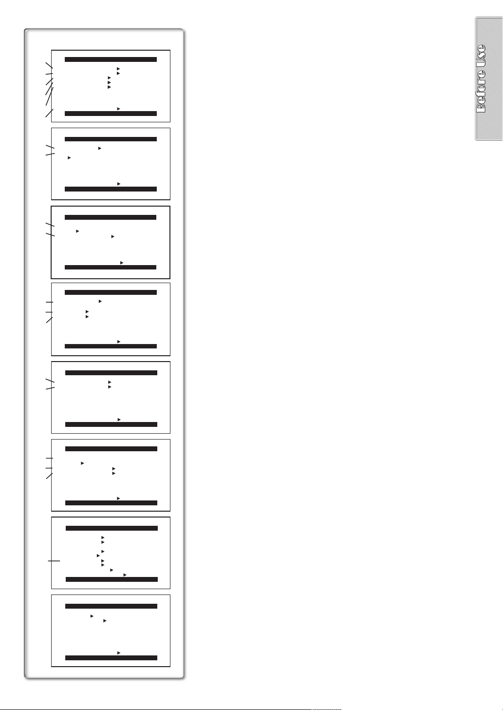
VCR Mode Main-Menu [VCR FUNCTIONS]
1)
2)
3)
PLAYBACK FUNCTIONS
BLANK SEARCH ---- YES
RECORD TO CARD ---- YES
INDEX PHOTO SCENE
AUDIO
AUDIO OUT
ST1 ST2 MIX
STEREO L R
4)
5)
RETURN ---- YES
6)
7)
8)
9)
10)
11)
12)
13)
PUSH MENU TO EXIT
DIGITAL EFFECT
EFFECT OFF ON
EFFECT SELECT
OFF MULTI WIPE MIX
STROBE NEGA SEPIA
MONO TRAIL SOLARI
MOSAIC MIRROR
RETURN ---- YES
PUSH MENU TO EXIT
REC MODE
FINE NORMAL ECONOMY
CREATE TITLE
RETURN ---- YES
SCAN MODE
SPEED FAST NORMAL SLOW
SWING OFF ON
CARD SETUP
PUSH MENU TO EXIT
MULTI-PICTURES
STROBE MANUAL
PHOTO SCENE
[PLAYBACK FUNCTIONS] Sub-Menu
1) Blank Search [BLANK SEARCH] (l 29)
2) Recording to Card [RECORD TO CARD] (l 35)
3) Index Search Mode [INDEX] (l 30)
4) Audio Output Mode [AUDIO] (l 33)
5) Audio Selector [AUDIO OUT] (l 48)
6) Returning to the Main-Menu [RETURN]
[DIGITAL EFFECT] Sub-Menu
7) Digital Effect On/Off [EFFECT] (l 31, 32)
8) Digital Effect Selection [EFFECT SELECT] (l 31, 32)
[CARD SETUP] Sub-Menu
9) Picture Quality [REC MODE] (l 34)
10) Title Creation [CREATE TITLE] (l 37)
---- YES
[MULTI-PICTURES] Sub-Menu
11) Multi-Picture Mode [SCAN MODE] (l 32)
12) Strobe Multi-Picture Speed [SPEED] (l 32)
13) Swing Mode [SWING] (l 32)
RETURN ---- YES
PUSH MENU TO EXIT
14)
15)
16)
17)
18)
19)
RECORDING SETUP
REC-SPEED SP LP
AUDIO-REC 12bit
RETURN ---- YES
PUSH MENU TO EXIT
AV IN/OUT SETUP
AV JACK
A.DUB INPUT
DV OUT
RETURN ---- YES
IN/OUT OUT/PHONES
OFF ON
PUSH MENU TO EXIT
DISPLAY SETUP
DATE/TIME OFF D/T DATE
C.DISPLAY LINEAR MEMORY
T.CODE
C.RESET ---- YES
DISPLAY ALL PARTIAL OFF
REC DATA OFF ON
LCD MODE NORMAL BRIGHT
LCD/EVF SET ---- YES
RETURN ---- YES
PUSH MENU TO EXIT
OTHER FUNCTIONS
REMOTE VCR1 VCR2 OFF
CLOCK-SET ---- YES
RETURN ---- YES
PUSH MENU TO EXIT
16bit
MIC AV IN
[RECORDING SETUP] Sub-Menu
14) Recording Speed Mode [REC-SPEED] (l 19, 41, 42)
15) Audio Recording Mode [AUDIO-REC] (l 19, 33)
[AV IN/OUT SETUP] Sub-Menu
16) AV Jack [AV JACK] (l 33, 41, 48)
17) Audio Dubbing Input [A.DUB INPUT] (l 33)
18) AD Conversion Output [DV OUT] (l 41)
[DISPLAY SETUP] Sub-Menu
(l 16)
19) Camera Data [REC DATA]
≥If you set [REC DATA] to [ON], the settings (shutter speed, iris (l 47)
and white balance settings (l 47), etc.) used during the recordings are
displayed during playback. [---] appears on the display when there is no
data.
≥The setting information may not displayed properly if the camera data of
this Camera/Recorder is played back on other equipment.
The camera data will not be recorded in the following cases:
When the data is recorded from a card to a tape.
≥
When recording proceeds with no input signals supplied.
≥
When recording involves the use of the S-Video or AV Input Jack.
≥
When pictures with no camera data are recorded using the DV
≥
Terminal.
When displaying a list of titles.
≥
[OTHER FUNCTIONS] Sub-Menu
≥Same as described on page 16.
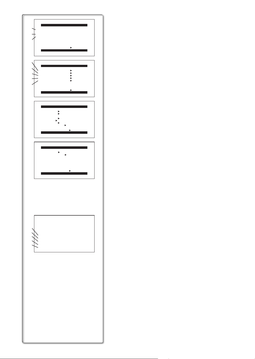
Card Playback Mode Main-Menu
DELETE PICTURE/TITLE
1)
1.
DELETE PICTURE
BY SELECTION
2.
DELETE ALL PICTURES
2)
3.
DELETE TITLE
3)
4)
5)
6)
7)
BY SELECTION
RETURN ---- YES
PUSH MENU TO RETURN
CARD EDITING
RECORD TO TAPE ---- YES
PICTURE SEARCH ---- YES
FILE LOCK ---- YES
DPOF SETTING ---- YES
CARD FORMAT ---- YES
8)
RETURN ---- YES
PUSH MENU TO EXIT
DISPLAY SETUP
DATE/TIME OFF D/T DATE
C.DISPLAY LINEAR MEMORY
T.CODE
C.RESET ---- YES
DISPLAY ALL PARTIAL OFF
LCD MODE NORMAL BRIGHT
LCD/EVF SET ---- YES
RETURN ---- YES
PUSH MENU TO EXIT
OTHER FUNCTIONS
REMOTE VCR1 VCR2 OFF
CLOCK-SET ---- YES
[DELETE PICTURE/TITLE] Sub-Menu
1) Selecting and deleting a Picture [DELETE PICTURE BY SELECTION]
(l 38)
2) Deleting All Pictures [DELETE ALL PICTURES] (l 38)
3) Selecting and Deleting a Title [DELETE TITLE BY SELECTION] (l 38)
[CARD EDITING] Sub-Menu
4) Recording to Cassette [RECORD TO TAPE] (l 36)
5) Searching a Picture [PICTURE SEARCH] (l 36)
6) Setting the File Lock [FILE LOCK] (l 38)
7) Setting DPOF [DPOF SETTING] (l 39)
8) Formatting a Card [CARD FORMAT] (l 39)
[DISPLAY SETUP] Sub-Menu
≥Same as described on page 16.
[OTHER FUNCTIONS] Sub-Menu
≥Same as described on page 16.
RETURN ---- YES
PUSH MENU TO EXIT
9)
10)
PICTURE SEARCH
11)
DELETE PICTURE
12)
FILE LOCK
DPOF SETTING
13)
EXIT
Card Playback Mode Short-Cut Menu
Short-cut menus enable some of the Card Playback Mode menus to be called
quickly. Press the [PUSH] Dial to display the short-cut menus, and rotate the
[PUSH] Dial and then press it to select the desired menu.
9) [PICTURE SEARCH]:
The [PICTURE SEARCH] menu for searching pictures from numbers
appears.
10) [DELETE PICTURE]:
The [DELETE PICTURE] menu for erasing the displayed picture
appears. Use this menu after the picture to be erased has appeared.
11) [FILE LOCK]:
The [FILE LOCK] menu to prevent the accidental erasure of the
displayed picture (lock setting) appears. Use this menu after the picture
to be locked has appeared.
12) [DPOF SETTING]:
The [DPOF SETTING] menu for performing the DPOF settings for the
displayed picture appears. Use this menu after the picture whose DPOF
settings are to be performed has appeared.
13) [EXIT]: This is for exiting from the short-cut menu.
 Loading...