

Page 1
Operation and Maintenance Manual for the
SODRTEK
ST 300 Analog Convective
®
Soldering/Desoldering System
P/N 5050-0536
Page 2

TITLE PAGE
General Information
Introduction...........................................................................................................3
ST 300 Handpiece................................................................................................3
Specifications .......................................................................................................3
Parts Identification................................................................................................4
Safety.............................................................................................................................5
Safety Guidelines.................................................................................................5
Usage Warnings/Cautions....................................................................................5
Servicing Precautions...........................................................................................6
System Set-Up...............................................................................................................6
Power Source...........................................................................................................6
Tip & Tool Stand......................................................................................................7
Vacuum Pick............................................................................................................7
Nozzle Changeout..........................................................................................................7
Removal..................................................................................................................7
Installation...............................................................................................................8
System Power Up ..........................................................................................................8
Operation........................................................................................................................8
Variable Temperature Control..............................................................................8
LED Operation......................................................................................................8
Variable Airflow Control........................................................................................8
Handpiece Vacuum/Pressure...............................................................................9
Component Removal............................................................................................9
Component Installation........................................................................................10
PikVac Operation ................................................................................................11
Corrective Maintenance................................................................................................12
Packing List...................................................................................................................13
Spare Parts...................................................................................................................13
Service ..........................................................................................................................13
SODRTEK by PACE” LIMITED WARRANTY STATEMENT........................................14
Contact Information.......................................................................................................15
©2004 PACE Inc., Annapolis Junction, Maryland Page 2 of 15
All Rights Reserved
Page 3

General Information
Introduction
Thank you for purchasing the PACE SODRTEK
®
model ST 300 Analog Convective
Soldering/Desoldering System. This manual will provide you with the information necessary to
properly set up, operate and maintain the ST 300.
Please read this manual thoroughly before using the unit. The ST 300 system is a complete system
designed for hot air removal and installation of SMD components, including Ball Grid Arrays (BGAs).
The following key features allow process controlled placement and reflow of BGAs and SMD
components.
ST 300 Handpiece
The user-friendly ST 300 static-safe handpiece incorporates a powerful heater and has easy-access
heat cycle and vacuum pick switches on the handle. A built-in, self-adjusting vacuum pick has a pushpull action, allowing components to be lifted automatically after solder reflow. When utilized with the
ThermoFlo System work platform, the handpiece is easily converted to a precision reflow head.
The ST 300 unit is available in either the 115 VAC or 230 VAC version. The 230 VAC version system
bears the CE Conformity Marking which assures the user that it conforms to all the requirements of
(EU) directive EMC 89/336/EEC & 73/23/EEC.
Specifications
ST 300 - Operates on 97-127 VAC, 60 Hz (115 VAC version)
575 Watts maximum at 120 VAC, 60 Hz
ST 300E - Operates on 197-264 VAC, 50 Hz (230 VAC version)
575 Watts maximum at 230 VAC, 50 Hz
Air Temperature Range - 149°C - 482°C (300°F - 900°F)
Blower Air Flow Rate (measured at heater) - 20 SLPM (0.7 SCFM) minimum at highest speed (9).
- 5 SLPM (0.18 SCFM) minimum at lowest speed (1).
Vacuum (at Pik-Vac Port) - 7.6 cm Hg. (3 in. Hg.) minimum.
NOTE: The ST 300 is designed for cyclical usage. Attempts to use in continuous operations by
taping the handpiece Cycle Switch or other methods will void Blower Assembly warranty.
Component Capacity - (maximum size) - 5.1 cm x 5.1 cm (2” x 2”)
Physical Parameters
Size - 133 mm H x 260 mm W x 248 mm D (5.25” H x 10.25” W x 9.75” D)
Unit Weight - 4.3 Kg. (9.5 lbs.)
©2004 PACE Inc., Annapolis Junction, Maryland Page 3 of 15
All Rights Reserved
Page 4
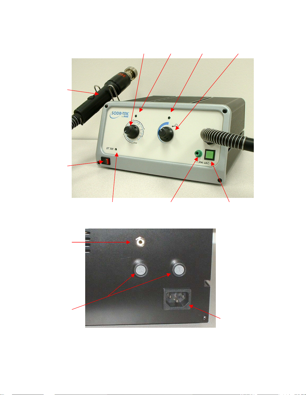
Parts Identification
p
Handpiece
Power Switch
Earth Ground Rece
Fuses
tacle
Variable Temperature
Selection Knob
Temp LED Blower LED
Variable Blower
Speed Knob
Power On LED LoFlo Vacuum Port Illuminated LoFlo
Pump Switch
AC Power Receptacle
©2004 PACE Inc., Annapolis Junction, Maryland Page 4 of 15
All Rights Reserved
Page 5

Safety
Safety Guidelines
The following are safety precautions that personnel must understand and follow when using or
servicing this product.
“NOTE”
Used to indicate a statement of company recommendation or policy. The message may relate
directly or indirectly to the safety of personnel or protection of property. NOTE is not associated
directly with a hazard or hazardous situation and is not used in place of "CAUTION", "WARNING"
or "DANGER".
“CAUTION”
Used to indicate a hazardous situation, which may result in minor or moderate injury. May also be
used to alert personnel to conditions, procedures and practices which, if not observed, could
result in damage to or destruction of the product or other equipment.
“WARNING”
Used to define additional information that if not closely followed might result in serious damage to
equipment and represent a potential for serious personnel injury.
“DANGER”
Defines additional information that if not closely followed might result in severe personnel injury or
death. Danger is not used for property damage unless personal injury risk is present.
Usage Warnings/Cautions
WARNINGS
1. A fire hazard may arise if the ST 300 is used improperly.
2. Do not use the ST 300 in the presence of an explosive atmosphere.
3. Be careful when using the ST 300 in places where there are combustible materials. Heat
may be conducted to combustible materials which are out of sight.
4. Do not apply heat from the ST 300 to one place for a long time.
5. Do not leave the ST 300 unattended while powered on.
CAUTIONS
1. The ST 300 handpiece heater assembly housing and any installed nozzle are hot when
the system is being cycled and for a period of time thereafter. DO NOT touch either the
heater assembly housing, nozzle or direct heated air stream. Severe burns may result!
2. Always use the handpiece with the Heat Shield installed except when the handpiece is
mounted to its work platform. The Heat Shield helps to prevent unintentional contact with
the heater.
©2004 PACE Inc., Annapolis Junction, Maryland Page 5 of 15
All Rights Reserved
Page 6

3. Utilize all standard electrical safety precautions when using this or any other electrical
equipment.
4. Always use this system in a well-ventilated area. A fume extraction system such as those
available from PACE are highly recommended to protect personnel from solder flux
fumes.
5. Exercise proper precautions when using chemicals (e.g., solder paste). Refer to the
Material Safety Data Sheet (MSDS) supplied with each chemical and adhere to all safety
precautions recommended by the manufacturer.
Servicing Precautions
DANGERS
POTENTIAL SHOCK HAZARD - Repair procedures performed on this product should be
performed by qualified service personnel only. Line voltage parts will be exposed when
equipment is disassembled. Service personnel must avoid contact with these parts when
troubleshooting.
Precautions
The following are general safety precautions that personnel must understand and follow when
using or servicing this product. These precautions may or may not be included elsewhere in this
manual.
Safety
Electrical Requirements
The ST 300 unit draws approximately 575 Watts, which is listed on the nameplate on the
power source rear panel. A separate, dedicated AC supply line circuit may be required to
adequately power the unit/system. If your power outlet cannot provide suitable power,
arrange for a qualified, licensed electrician to install one for you.
System Set-Up
Power Source
Set up the ST 300 system using the following steps and associated drawings.
1. Remove the ST 300 from its shipping container(s). Store the shipping container(s) in a
convenient location. Reuse of these containers will prevent damage if you ship or store
the system.
2. Set the ST 300 unit on a convenient workbench.
3. Place the POWER Switch (on power source front panel) in the
"OFF" or "0" position.
4. Inspect all system components, check for shipping damage, and ensure that all
purchased components (standard and options) are present. Use the drawings provided
in the following pages as a guide for checking the parts that come with the unit.
©2004 PACE Inc., Annapolis Junction, Maryland Page 6 of 15
All Rights Reserved
Page 7

Tip & Tool Stand
Using the supplied hardware, attach the Handpiece
Retainer and the Mounting Bracket as shown.
Handpiece
Retainer
Mounting
Bracket
Need hose retention kit
Get with Vince on
Tuesday
Vacuum Pick
Set-Up
1. Locate the Pik-Vac (P/N 7027-0001-P1) and the Vacuum
Cup Kit (P/N 6993-0154) supplied with the system.
2. Attach the ridged end of a male quick connect hose mount
Fitting to each end of the Air Hose.
3. Attach one male quick connect hose Fitting (with attached
Air Hose) to the rear of the Pik-Vac Handpiece.
4. Insert the other male quick connect hose
Fitting (with attached Air Hose) into the LoFlo Vacuum Port.
5. Attach the Metal Vacuum Tip, with the appropriate vacuum cup, to
the end of the Pik-Vac Handpiece.
Nozzle Changeout
Removal
WARNING: Never remove a heated nozzle using bare hands. Use the Rubber
Pad. Never use a wrench or pliers when removing a nozzle.
1. While holding the Rubber Pad, gently twist the nozzle as shown. The nozzle
will easily release from the Nozzle Adapter.
2. Place the nozzle (still hot) on a heat resistant surface.
©2004 PACE Inc., Annapolis Junction, Maryland Page 7 of 15
All Rights Reserved
Page 8

Installation
1. Select the proper Nozzle for your application; see the “Replacement
Parts” section of this manual.
2. Orient the Nozzle for best use on the component.
3. Insert the Nozzle up into the Nozzle Adapter (use Rubber Pad if nozzle
is hot). Gently twist the nozzle as shown to lock nozzle in place.
System Power Up
1. Insert the female end of the power cord into the AC Power Receptacle on the rear panel of
the power source.
2. Plug the prong end (male end) of the power cord into an appropriate 3 wire grounded AC
supply receptacle.
CAUTION: To insure operator and ESD/EOS safety, the AC power supply receptacle must be
checked for proper grounding before initial operation.
Operation
LED Power Indicator
Variable Temperature Control
Adjust the Variable Temperature Control Knob to the desired temperature setting.
Notice that the control panel has an outer graphic scale denoting temperature in °C
(Celsius) and an inner graphic scale denoting temperature in °F (Fahrenheit).
These numerical scales denote the set tip temperature times 100 (e.g., “3” on the
outer scale is 3 x 100 or 300°C).
LED Operation
The Green colored Temperature LED on the power source front panel indicates System Status.
LED Full On - Continuous power is being delivered to the handpiece. This condition is evident
when the system is first powered up (handpiece heater cold) or the Variable Temperature Control
setting is increased.
LED Flashing - Indicates that the set tip temperature (as set on the Variable Temperature
Control) has been reached. Power to the handpiece is cycling Off and On to maintain set
temperature.
LED Off - No power is being delivered to the handpiece heater. This condition is evident for a
short period of time when set temperature is reached and stabilizing or if the Variable
Temperature Control setting is decreased. If the LED
never illuminates, check for a faulty
handpiece heater (see Corrective Maintenance section).
Variable Airflow Control
Adjust the Variable Airflow Control Knob to the desired airflow setting.
NOTE: The Variable Airflow Control LED will be illuminated whenever the ST 300
blower is running.
©2004 PACE Inc., Annapolis Junction, Maryland Page 8 of 15
All Rights Reserved
Page 9

Handpiece Vacuum/Pressure
The Air Hose and Slide Rod must be positioned to prevent any kinking of the Hose. Kinks in the Hose
will prevent proper airflow when the system is operated and will cause a deterioration in performance.
Component Removal
1. Install the proper Nozzle Assembly and Vacuum Cup onto the handpiece. Ensure that the PCB
assembly to be reworked and any replacement component have been properly prepared.
NOTE: Any required preheating operating should be completed before advancing beyond this
point.
2. Set unit POWER Switch (on power source front panel) to the ON p osition.
3. Adjust the Temperature as desired using the Variable Temperature Control Knob.
4. Adjust the Airflow as desired using the Variable Airflow Control Knob.
5. If using a Single Jet Nozzle, no vacuum cup is used; proceed to step 10.
6. Using the Vacuum Pick Adjust Control, adjust the vacuum cup to a point
where the bottom of the vacuum cup is flush with the bottom edge of the
nozzle.
7. Ensure that the Nozzle is square to the PCB.
8. Lower the nozzle:
a) Approximately 1mm (.040”) above the PCB when using a Box nozzle.
b) Approximately (depending on component) 1mm (.040”) above the PCB
when using a Pattern nozzle.
c) Contacting BGA component when using a Vented Air Nozzle (V-A-N).
9. Press and release handpiece Vacuum Pick Swit ch to activate vacuum.
10. For Single Jet nozzles, hold the end of the nozzle tube above the
rework area at a height and angle which gives the best results in your
particular application.
11. Press and hold the handpiece Cycle Switch to activate heat cycle.
12. When complete solder melt is observed, gently lift the handpiece to remove the component from
the PCB. When using a Curved, Single Jet nozzle, use a vacuum pickup device or tweezers to lift
the component from the PCB; steps 13 & 14 are not used.
13. Position the nozzle (with component) over a heat resistant surface.
14. Press and hold the Vacuum Pick Switch for 0.5 second (minimum) to
deactivate vacuum and release component.
©2004 PACE Inc., Annapolis Junction, Maryland Page 9 of 15
All Rights Reserved
Page 10

WARNING: The component is HOT! DO NOT remove or catch the component with bare hands.
Component Installation
1. Install the proper Nozzle and Vacuum Cup (if not using Single Jet nozzle) onto the
handpiece.
2. Set the unit POWER Switch (on front panel of power source) to the ON po sition.
3. Adjust the Temperature as desired using the Variable Temperature Control Knob.
4. Adjust the Airflow as desired using the Variable Blower Control Knob.
5. Press and release Handpiece Vacuum Pick Switch to activate vacuum.
NOTE: As an alternative to the component placement methods shown below in
6. Position the component directly beneath and square to nozzle.
a) When using Box or V-A-N nozzles, insert component body into the bottom
of the nozzle. BGA components will rest against the walls of the nozzle.
b) When using Pattern nozzles, position component leads beneath and in
line with the air jets on the nozzle.
c) When using a Curved, Single Jet nozzle, position the component on its
land pattern (prefilled or with solder paste deposition). Solder tack
lead(s) if necessary.
7. If using a Single Jet nozzle proceed to step 12.
8. Using the Vacuum Pick Adjust Control on the handpiece, adjust the vacuum cup to a point
where the bottom of the vacuum cup touches the component body. The component is now
held in position with the vacuum cup.
9. Using the Vacuum Pick Adjust Control, adjust the position of the component:
a) To a spacing (depending on component) of 1-1.5mm (.040-.060”) between
the bottom of the component and the bottom of the nozzle when using a
Box or Pattern nozzle.
b) To contact a BGA component when using a V-A-N nozzle.
10. Lower nozzle (with component) to a point where the component
leads/contacts rest gently on or just above the component land pattern.
Allow the component to drop onto the heat resistant surface. Allow sufficient time
for the component and PCB to cool to room temperature before handling.
steps 7 through 10, the component (except BGAs) may be positioned and
solder tacked in place on land pattern. See “Component Positioning”.
©2004 PACE Inc., Annapolis Junction, Maryland
All Rights Reserved
Page 10 of 15
Page 11

NOTE: If component has been prepositioned on land pattern, lower nozzle to desired height
above PCB. A height of 1-1.5mm (.040-.060") above the PCB when using Box or
Pattern nozzles is recommended.
11. Ensure that the handpiece is held vertical to the PCB (except with Single Jet nozzles).
12. For Single Jet nozzles, hold the end of the nozzle tube above the rework area at a height and
angle which gives the best results in your particular application.
NOTE: Any required preheating should be completed before advancing beyond this point.
13. Press and hold the handpiece Cycle Switch to activate heat cycle.
Heated air is now being applied to the rework area.
14. If using a Single Jet nozzle in a hand held operation, move the
handpiece as necessary to direct air flow to the solder areas
requiring reflow.
15. If vacuum is being used to hold component, depress and hold the Vacuum
Pick Switch for 0.5 second (minimum) to stop vacuum and release the
component. Release the Vacuum Pick Switch.
16. When complete solder melt is observed, release the handpiece Cycle Switch
(to cease air flow) and gently lift the handpiece from the PCB.
Pik-Vac Operation
1. Use of the Metal Vacuum Tip without a Vacuum Cup attached for removal/replacement of very
small component works well but for larger components, install one of the supplied Vacuum
Cups onto the tip. For best results, use a size slightly smaller than the body of the component
to be removed or placed. For very large components, use the largest Vacuum Cup.
2. Press the Illuminated LoFlo Pump Switch to activate vacuum at the handpiece. The LoFlo
Pump Switch will illuminate whenever the switch is depressed.
3. Grasp the handpiece as you would a pen, with the
Vacuum Cup (or tip) pointing down and the Vacuum
Control Port pointing up.
©2004 PACE Inc., Annapolis Junction, Maryland
All Rights Reserved
Page 11 of 15
Page 12

4. Place the Vacuum Cup and/or the Metal Vacuum Tip gently onto the top surface of the
Component body. Exercise caution to avoid bending of leads on fine pitch devices.
5. Place one finger over the Vacuum Control Port. Vacuum is now being applied to the
Component body.
6. Gently lift the Component off the PC Assembly (removal operation) or out of the component
holder (placement operation).
7. Lower the Component gently into position onto the PC Assembly (placement operation) or
component holder (removal operation).
8. Lift finger or gently slide finger back from the Vacuum Control Port to release the Component.
9. Press the Illuminated LoFlo Pump Switch again to turn off the LoFlo Pump when all Component
handling operations are completed.
Corrective Maintenance
Power Source
Refer to the table below. Most malfunctions are simple and easy to correct.
Symptom Probable Cause Solution
No power to system
Heater Assembly does
not heat
Little or no air flow,
heater heats and
blower is running
Little or no vacuum Worn vacuum
Vacuum Cup will not
hold component
Vacuum Pickup Rod
binding
Blown Fuse Inspect and replace the fuse(s) located on the
power source rear panel
Line cord
unplugged
Open Heater Contact PACE for assistance
Kinked air hose Change routing of air hose to remove
pump
Worn or broken
vacuum cup
Vacuum Pickup
rod is bent
Plug line cord into the appropriate AC outlet
kinks
Replace vacuum pump. Contact PACE for
assistance.
Replace vacuum cup
Contact PACE for assistance
©2004 PACE Inc., Annapolis Junction, Maryland Page 12 of 15
All Rights Reserved
Page 13

Packing List
Item # Description Part Number ST 300
Only
1 System Power Supply 7008-0276-01 1 0
2 System Power Supply (Export) 7008-0276-02 0 1
3 Power Cord, 115V 1332-0094 1 0
4 Power Cord, 230V 1332-0093 0 1
5 PV-65 Handpiece 7027-0001-P1 1 1
6 Nozzle Adapter 4028-0001-P1 1 1
7 Hose Retention Kit 6018-0096-P1 1 1
8 Cubby 6019-0048-P1 1 1
9 Hot Grip Removal Pad 1100-0307-P1 1 1
10 Operations Manual CD CD5050-0459 1 1
Spare Parts
Item # Description PACE Part Number
Fuse, 7 A, 125 V, Fast Acting (ST 300) 1159-0274-P5 1
Fuse, 5 A, 230 V, Fast Acting (ST 300E) 1159-0266-P5
2 Fuse, 1 A, 125 V, Time Lag (ST 300) 1159-0246-P5
Fuse, 500 mA, Time Lag, (ST 300E) 1159-0213-P5
Service
Please contact PACE or your local distributor for service and repair.
ST 300 E
Only
©2004 PACE Inc., Annapolis Junction, Maryland Page 13 of 15
All Rights Reserved
Page 14

PACE Incorporated retains the right to make changes to specifications contained herein at any time,
without notice. Contact your local authorized PACE Distributor or PACE Incorporated to obtain the latest
specifications.
The following are trademarks and/or service marks of PACE, Incorporated, MD, USA:
INSTACAL
POWERPORT
™
, FUMEFLO™, HEATWISE™, PACEWORLDWIDE™, PERMAGROUND™,
™
, POWERMODULE™, TEMPWISE™, TIP-BRITE™, AUTO-OFF™, and
TEKLINK™.
The following are registered trademarks and/or service marks of PACE Incorporated, Annapolis Junction
Maryland U.S.A.
ARM-EVAC
SODRTEK
VISIFILTER
®
, FLO-D-SODR®, MINIWAVE®, PACE®, SENSATEMP®, SNAP-VAC®,
®
, SODR-X-TRACTOR®, THERMOFLO®, THERMOJET®, THERMOTWEEZ®,
®
, THERMO-DRIVE®, and TOOLNET®.
PACE products meet or exceed all applicable military and civilian EOS/ESD, temperature stability and
other specifications including MIL STD 2000, ANSI/JSTD 001, IPC7711, and IPC A-610.
www.paceworldwide.comT
PACE USA PACE Europe
9030 Junction Drive Sherbourne House
Annapolis Junction, MD 20701 Sherbourne Drive
USA Tilbrook, Milton Keynes
MK7 8HX
United Kingdom
Tel: (301) 490-9860 (44) 01908-277666
Fax: (301) 498-3252 (44) 01908-277777
©2004 PACE Inc., Annapolis Junction, Maryland Page 15 of 15
All Rights Reserved
 Loading...