

Page 1

MBT 250/220 CALIBRATION KIT
PACE P/N 6993-0133
OPERATION & MAINTENANCE
INSTRUCTIONS
MANUAL NUMBER 5050-0288
REV . A
For any questions regarding the following instructions, contact your local authorized
P ACE dealer or contact P ACE directly at:
Telephone (301) 490-9860, Fax (301) 604-9215
PACE Incorporated
9893 Brewers Court
Laurel MD 20723-1990
1
Page 2

PACE Incorporated retains the right to make changes to specifications contained
herein at any time, without notice.
Contact your local authorized P ACE Distributor or PACE Incorporated to obtain the
latest specifications.
The following are registered trademarks and/or servicemarks of P ACE Incorporated,
Laurel Maryland U.S.A. and may only be used to identify genuine P ACE products or
services:
Cir-Kit, ComForm I, ConducT weez, CRAFT , Dual Path, Flo-D-Sodr, FuseSet,
HotSpot, LapFlo, MBT , MicroChine , Micro Portable, MiniChine, P acenter,
P A CE, P ed-A-V ac, PETS, PRC , PRINT, ResisTweez, SensaTemp, SMR,
Sodr-X-Tractor, StripTweez, SwaPlater, ThermoBand, ThermoPart,
ThermoPik, ThermoJet, ThermoTweez, Thermo-Drive, VisiFilter.
The following are trademarks and/or servicemarks of P ACE Incorporated, Laurel
Maryland U.S.A. and may only be used to identify genuine PACE products or
services:
AdapTip, Arm-Evac, DEXITEST, EK O, HandiPik,PIK-VAC, Pro-Evac,
Redi-Rak, SNAP-V AC , SR-3, SR-4, ST, Tip-Evac.
P ACE Incorporated has provided training on all of its products since 1958 as well as
advanced technology training in all aspects of hand soldering, rework and
repair.
Additional copies of this manual or other P ACE literature may be obtained
from:
P ACE Incorporated (301) 490 - 9860
Sales Administration (301) 4983252 Fax
9893 Brewers Court
Laurel MD 20723-1990
©1992 PACE Incorporated, Laurel MD. All rights reserved. Printed in the U.S.A.
2
Page 3
INTRODUCTION
The following procedure will allow you to effectively calibrate your MBT 250/220
system to insure accuracy and maintain peak performance.
Perform the following procedure step by step, in sequence, to:
1 . Alter Tip T emperature values.
2 . Alter Tip T emperature Offset values.
3. Determine and/or alter feature status and defaults stored in the system.
4 . Recalibrate the system for accuracy .
PROCEDURE
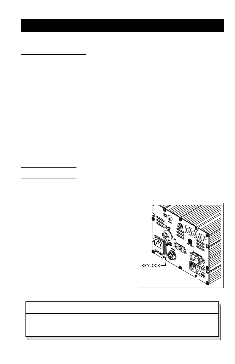
KEYLOCK OPTION
1 . An optional KeyLock feature is available
from P ACE which prevents unauthorized
alteration of stored data or calibration of
the system. Check the rear panel of the
system power source. If the KeyLock
feature is present there will be a KeyLock
switch located in the upper left portion of
the panel. Use the key to turn the switch
to the “Unlock” position. If the feature is
not present, there will be a round plastic
filler plug present at that location.
NOTE
The KeyLoc k switch must be turned to the “UNLOCK” position to alter any
of the data stored in memory or to recalibrate the system.
ENTERING CALIBRATION MODE
3
Page 4
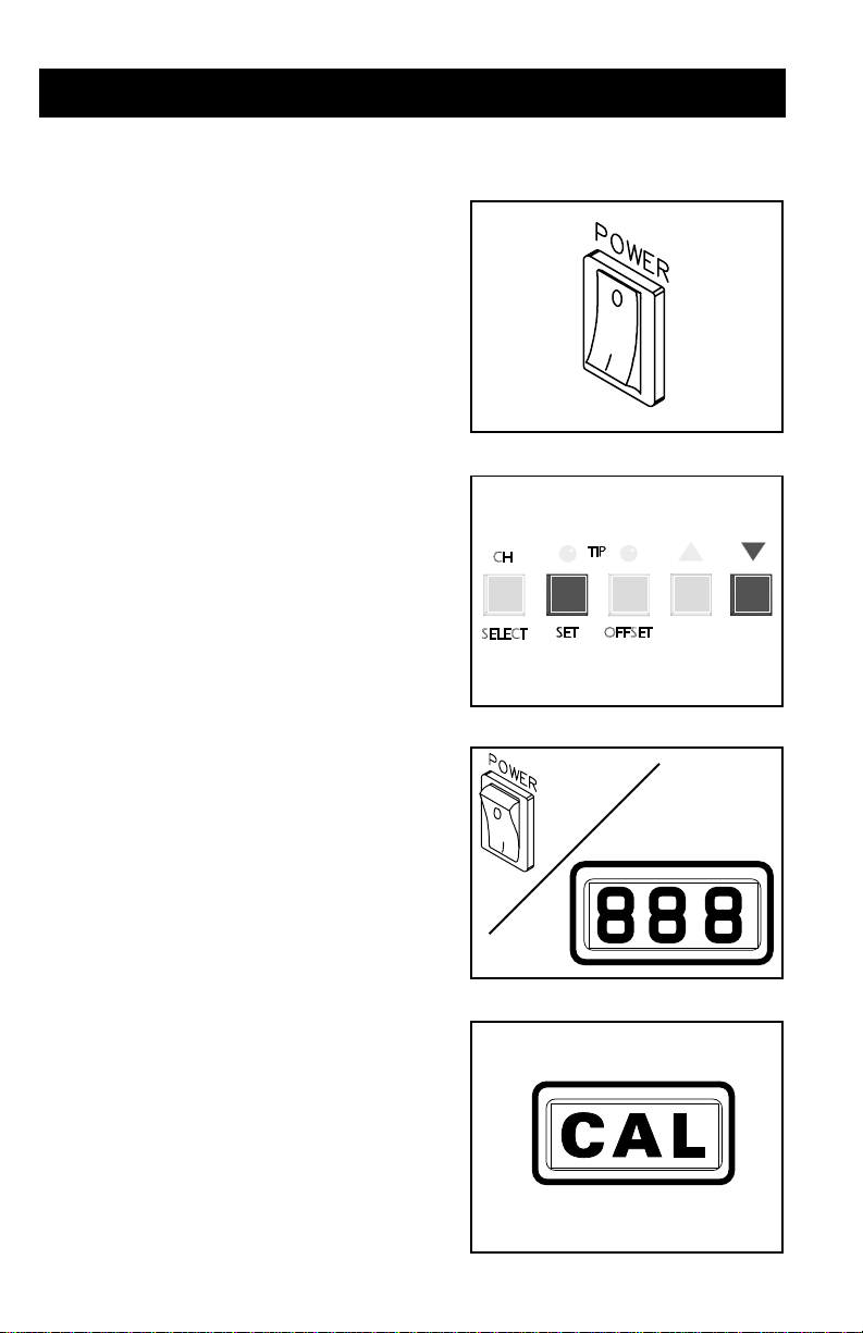
2. Place POWER Switch in the “OFF” (0)
position.
3. Press and hold the Tip Temperature Set
and Scroll Down Keys.
4. Place POWER Switch in the “ON” (1)
position. All of the system LEDs will light.
The T emperature Display will read “888”
and change to read “1-X”.
5 . Release the Tip T emperature Set and Scroll
Down Keys. The T emperature Display will
now read “CAL” and only the three
Channel LEDs will remain lit signifying
that the system is now in the Calibration
Mode.
°F/°C READOUT DEFAULT
6. Press and release the Tip Temperature Set
4
Page 5

Key . The Digital Readout will display
“S-X” (X = 1-9). Either the °F or °C will
be on. This is the default readout (e.g., if
the °C LED is on the Digital Readout will
display temperature readings in °C).
7 . Press and release the °F/°C Key to
change the default. Each subsequent
press and release of the key will change
the default.
AUTOMATIC SETBACK
8 . As received from the factory, the
temperature will read “S - -” meaning that
Automatic Setback is turned off. A
readout of 1 thru 9 on the right side of the Digital Readout indicates time
to Automatic Setback in increments of 10 minutes. For example, “S-3”
would indicate a timeout of 30 minutes.
To change the Automatic Setback
feature, press the Scroll Up Key to
increase the timeout and/or enable the
feature. Press the Scroll Down Key to
decrease the timeout.
9. Press the Tip Temperature Set Key to
store the °F/°C default and Automatic
Setback value in system memory. The
Digital Readout will revert to display
“CAL” and only the Channel 1 LED will
remain lit.
5
Page 6

AUTOMATIC SHUTDOWN
10. The system enables the Automatic
Shutdown feature only when the
Automatic Setback feature is
enabled. No additional steps are
necessary.
CHANNEL SELECTION
11 . The Channel 1 LED is now lit
signifying that Channel 1 is ready for
calibration. Perform steps 12
through 21 to calibrate. As channels
change, repeat these steps for each
channel.
NOTE
All temperature limits are stored in
system memory in degrees F.
LOWER TEMPERATURE LIMIT
SETPOINT
12. Press and release the Tip T emperature Set Key. The Digital Readout will
6
Page 7

now display “L-X” (X = 1-9). This is the stored value of the Lower
T emperature Limit in increments of 100°F.
For example, if the “L-5” is displayed, the
lower limit is 500°F .
13. Press Scroll Keys as necessary to
increase (Scroll Up Key) or decrease (Scroll Down Key) the Lower
T emperature Limit value.
14. Press and release the Tip Temperature Set
Key to store the display value into
memory.
UPPER TEMPERATURE LIMIT
SETPOINT
15. The Digital Readout now displays “H-X”
(X = 1-9). This is the stored value of the
Upper T emperature Limit in increments of
100°F in the same manner as the Lower
7
Page 8

T emperature Limit readout (see step 12).
16. Press Scroll Keys as necessary to
increase (Scroll Up Key) or decrease
(Scroll Down Key) the Upper
T emperature Limit value.
17. Press and release the Tip Temperature Set
Key to store the displayed value into
memory . The Digital Readout will now
display “C-1”.
NOTE
If you do not wish to recalibrate for readout
accuracy , press the TIP TEMPERA TURE
OFFSET Key and perform steps 12 through
17. After all channels have been calibrated,
you may exit the Calibration Mode by
pressing and releasing theTip T emperature
Offset Key again.
READOUT ACCURACY
18. Unplug the handpiece connected to the Current Channel and plug in the
#1 Calibration Assembly .
8
Page 9

19. Press and release the Tip Temperature Set
Key . The Digital Readout will flash “- - -”
to indicate that the system
microprocessor controlled circuitry is
recalibrating one aspect of the system
circuity. “C-2” will now be displayed.
20. Unplug the #1 Calibration Assembly and
plug in the #2 Calibration Assembly.
READOUT ACCURACY
CONT'D
21. Press and release the Tip Temperature Set
Key . The Digital Readout will flash “- - -”
to indicate that the system
9
Page 10

microprocessor controlled circuitry is recalibrating another aspect of the
system circuitry. “CAL” will now be
displayed indicating that calibration of
this channel is complete.
22. Press and release the Tip Temperature
Offset Key two times to exit calibration.
All values, features and defaults entered
during the calibration are now stored in
memory and all channel tip temperature
settings are turned “OFF”. All channel
Tip Temperature Offset settings are set to the default value of 6°F (3°C).
TEMPERATURE DISPLAY
MESSAGE CODES
Listed below are Message Codes and a
description of each which may be displayed on
the system power source digital readout during
the Calibration procedure.
10
Page 11

DISPLAY
DISPLAY
DISPLAYDISPLAY
MESSAGE
MESSAGE
MESSAGEMESSAGE
C-1 OR C-2
CAL Indicates that system is in the Calibration Mode.
E-5
DESCRIPTION
DESCRIPTION
DESCRIPTIONDESCRIPTION
Indicates system is ready to process Digital Readout accuracy
calibration for a particular channel using the appropriate
calibration module.
Input to control circuitry unstable. Indicates that no calibration
module is connected to the channel being calibrated or the
incorrect module has been inserted.
E-6
H-X
(X = 1 thru 9)
L-X
(X = 1 thru 9)
OFF
S--
S-X
--(flashing)
Loose connection. Calibration input is out of range. Normally
occurs if incorrect calibration module is inserted.
Indicates the Current Channel is ready to accept new Upper
Temperature Limit setpoint X (X times 100°F).
Indicates the Current Channel is ready to accept new Lower
Temperature Limit setpoint X (X times 100°F).
Setpoint for this channel is below Lower Temperature Limit
setpoint.
Indicates that the Automatic Temperature Setback (and Power
Down) feature is disabled (turned off).
Indicates that the Automatic Temperature Setback (and Power
Down) feature is enabled (turned on) and will set each channels'
Set Tip Temperature back after X times 10 minutes of handpiece
inactivity (non-use).
Indicates that the system circuitry is proceeding with calibration
using the proper calibration module (C-1 or C-2).
11
Page 12

12
 Loading...