

Page 1
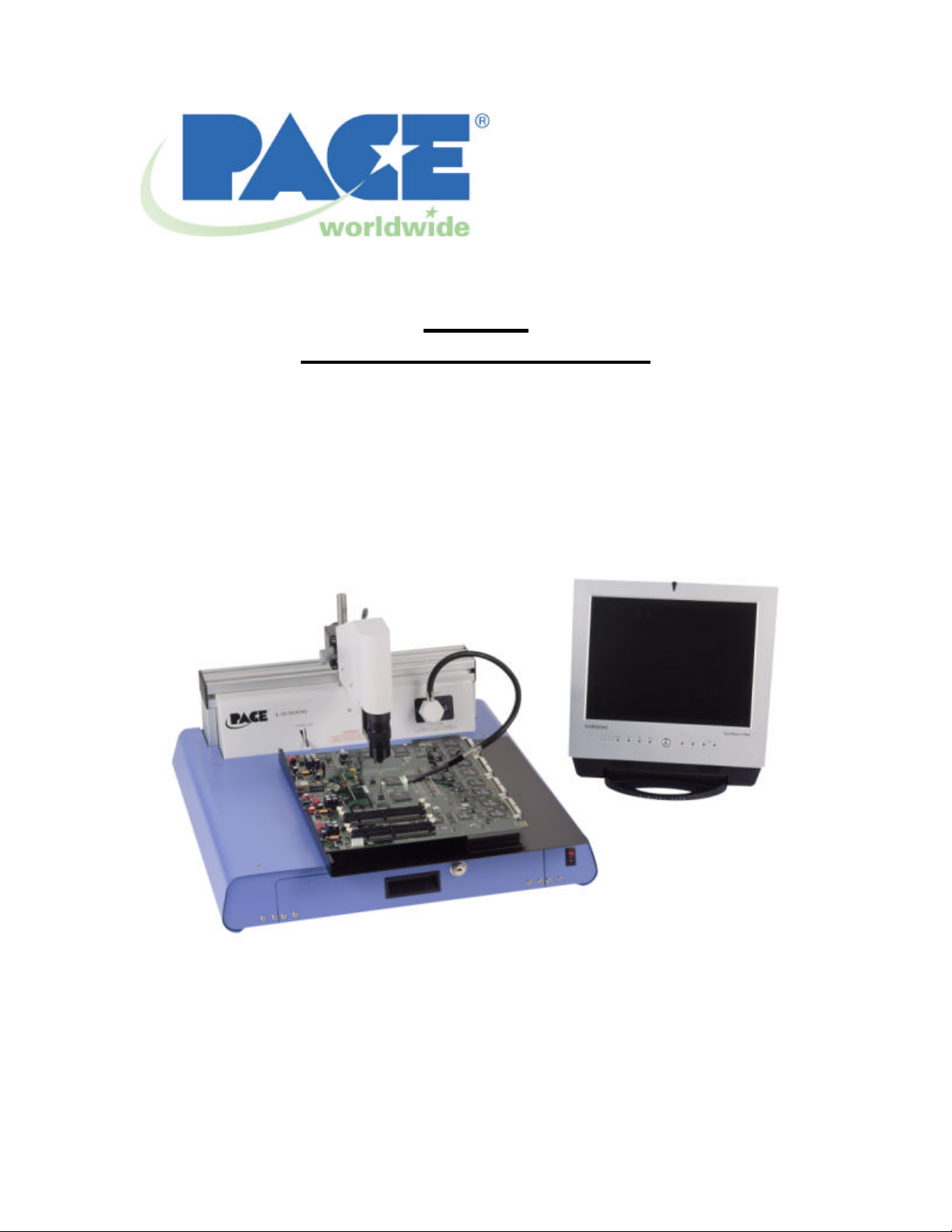
LS 3000
Optical Inspection System
Operation Manual
P/N 5050-0517
Rev A-CB
Page 2

System Operations Manual, Rev A
CAUTION: RIGID PROBE IS EXTREMELY FRAGILE. PLEASE USE
EXTREME CARE WHILE HANDLING AND USING
1. Packing Contents, Standard Items
a. Packing contents (Standard Items)
Description Part Number
Rigid Probe 1106-0046-P1
Fiber Probe End piece 1106-0049-P1
Large PCB Holder (2) 1400-0001-01-P1
Med PCB Holder (2) 1400-0001-02-P1
Small PCB Holder (4) 1400-0001-03-P1
Small PCB Tray 1400-0050-P1
Single Gooseneck 6007-0020-P1
2. Specifications:
120 VAC Unit 8007-0401
230 VAC Unit 8007-0402
Dimensions H: 510mm (20”) W: 635mm (25”)
D: 660mm (26”)
Weight 32kg (70lbs)
Magnification 100x – 375x with object 3.3mm
(13”) away from probe using a
381mm (15”) diagonal monitor
Field of View 1.5mm (.06”) – 6.35mm (.25”) with
object at 6.35mm (.25mm) away
from probe using 381mm (15”)
diagonal monitor
Focus Distance 0 – 228mm (9”) with 381mm (15”)
diagonal monitor
Minimum Standoff
.05mm (.002”)
Height (distance between
top of PCB and underside of
component)
Minimum Distance
2.54mm (.1”)
Between
Components
Optics Probe Fiber Optic rigid probe with
stainless steel protective cap
Lighting Type Adjustable Metal Halide Light
Source
Maximum PCB Size 510mm (20”) x 610mm (24”)
Camera Hi-Resolution CCD Camera
Agency Approvals CE
www.paceworldwide.com Page 2 of 20
Page 3
System Operations Manual, Rev A
Optional Accessories
- Flexible Optics Probe 0.38mm (.015”)
diameter. P/N 1106-0047-P1
- Dual Fiber Light Gooseneck. P/N 6007-
0021-P1
- 15” LCD Flat Panel Monitor P/N 7015-
0010
Right Angle Light Bar:
- 12.7mm (.5”) Wide: P/N 1106 -
0048-03-P1
- 25.4mm (1”) Wide: P/N 1106-
0048-02-P1
- 38.1mm (1.5”) Wide: P/N 1106-
0048-01-P1
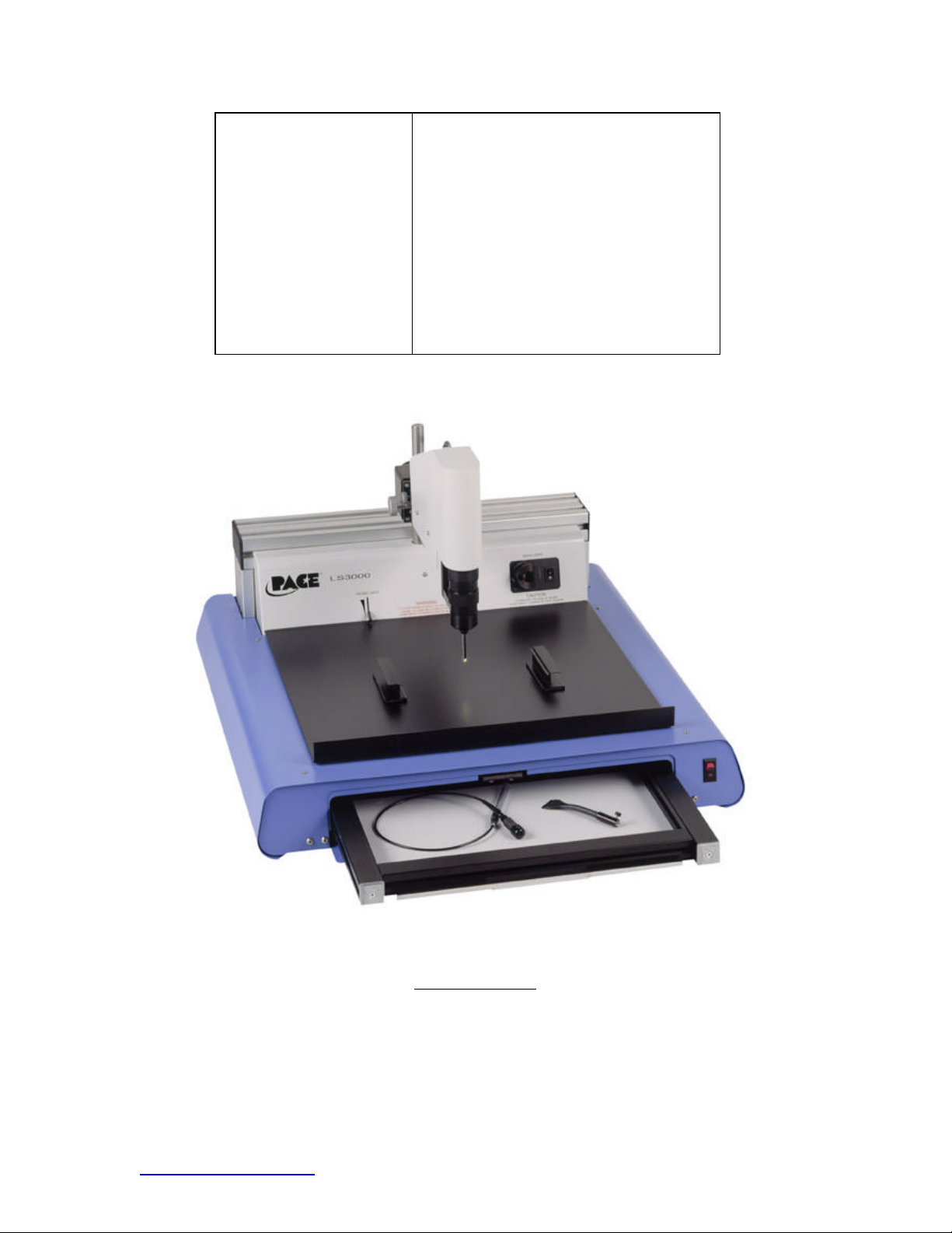
Figure 1: LS 3000
www.paceworldwide.com Page 3 of 20
Page 4

System Operations Manual, Rev A
3. Safety Information
a. Follow all manufacturer safety precautions listed in this manual.
b. Ensure system is used only in accordance with the following
procedures.
c. Immediately replace any worn or damaged items
d. Do not open the back panel while system is in use.
CAUTION: RIGID PROBE IS EXTREMELY FRAGILE. PLEASE USE
EXTREME CARE WHILE HANDLING AND USING
4. Features
a. The LS 3000 is the newest, cost effective, optical inspection system
specifically designed for today’s electronics. It’s primary use is for
inspection of area array devices including PBGA’s, CSP’s, Flip
Chips, LBGA’s, CBGA’s etc. However, the LS 3000 has a wide
range of other inspection used on any SMT or through-hole base
PCB. The LS 3000 is ideal for periodically monitoring the
performance of production or rework reflow equipment. It is also a
critical inspection/monitoring instrument for R&D labs and process
development departments when developing new processes of
troubleshooting problems.
b. The LS 3000 features a high resolution CCD chip camera and
incorporates industrial quality endoscopic components to acquire
images. The video signal can be sent to a stand-alone monitor or
can be routed to a PC via a video acquisition card. The system
comes standard with front lighting through the endoscope and with
back lighting from one fiber light gooseneck and one end piece.
Both back and front lighting can be adjusted independently. An
optional dual gooseneck for back lighting is also available. The
camera head on the LS 3000 can be moved in the Y direction using
a fine adjustment knob on the side of the system, which allows the
user to scan an entire side of a device with ease.
c. The LS 3000 verifies your process integrity so you can have
absolute confidence in your production or rework process.
5. Un-packing
Your LS 3000 system comes completely contained in one cardboard box,
which has been secured to a shipping palette. If you have purchased the
optional monitor, it will come packaged in it’s own box and will be attached
to the top of the system box.
www.paceworldwide.com Page 4 of 20
Page 5
System Operations Manual, Rev A
Starting with the LS 3000 container, please use the following steps to
safely unpack;
a. If your system came with the monitor, cut or loosen any straps,
which hold the monitor box to the main assembly box. Set monitor
box aside.
b. The cardboard box holding your LS 3000 will come strapped to a
palette. This can be left intact or the straps holding it to the palette
can be removed and the box removed from the palette.
c. Carefully cut any tape holding the main assembly box top together
and open the box top.
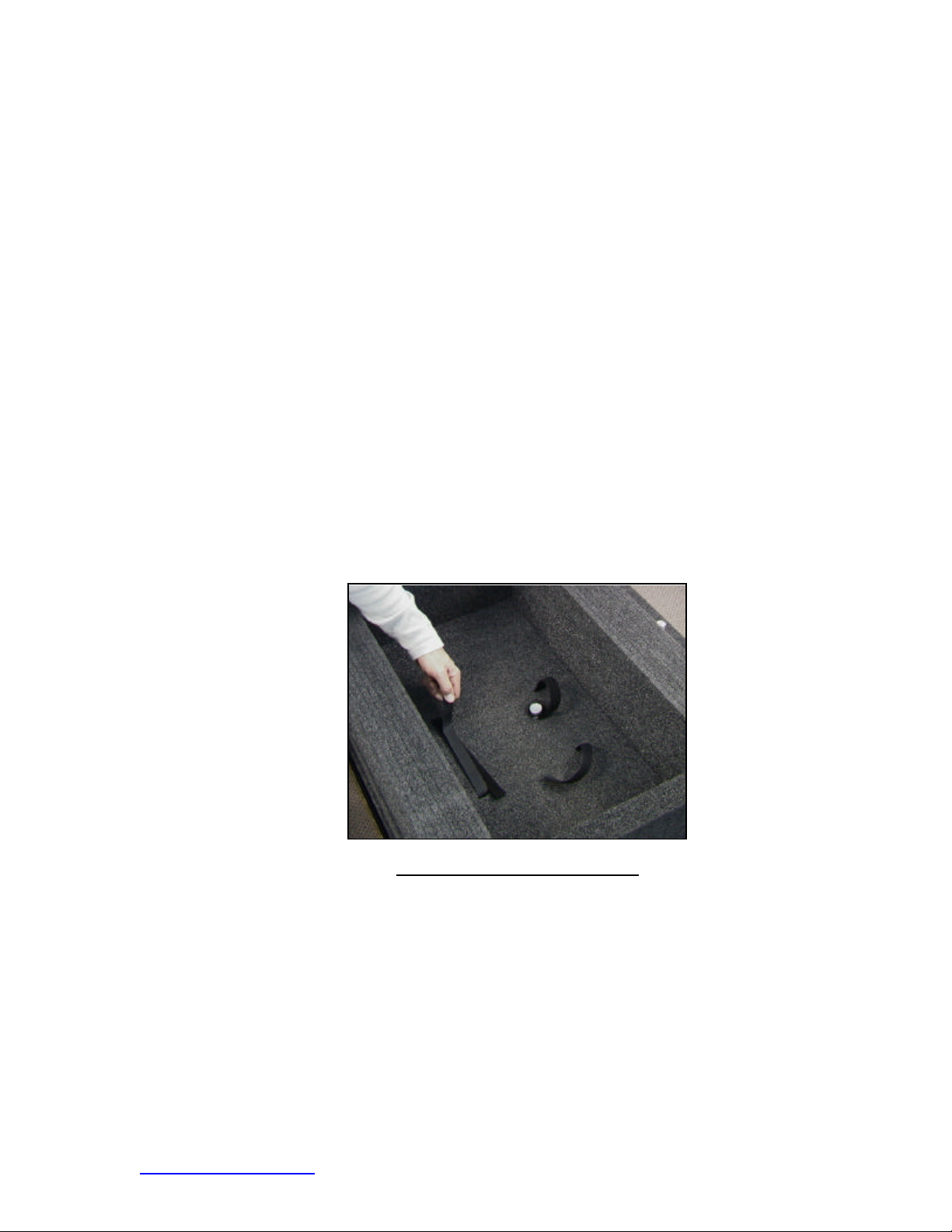
d. The interior of the box contains several, custom cut, foam packing
trays. The top packing tray will have a set of Velcro straps running
though it.
e. Un-do the Velcro straps as shown in figure 2 and carefully remove
the top foam-packing tray. This will reveal the camera head
assembly, which has been removed from the main system for
shipping.
Figure 2 Und oing the Velcro Straps
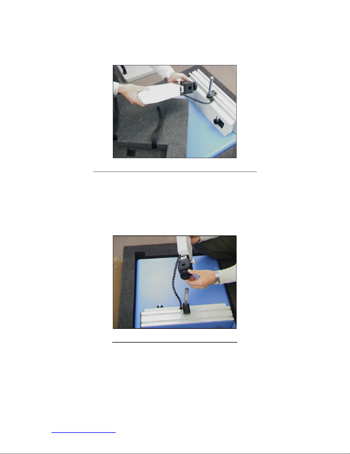
f. The camera head assembly is still connected to the main unit via
it’s wiring which will be clearly seen. Carefully lift the camera head
assembly without placing any strain on the wiring and remove the
second foam-packing tray as shown in figure 3. This is the packing
tray that previously cradled the camera head assembly.
www.paceworldwide.com Page 5 of 20
Page 6
System Operations Manual, Rev A
Figure 3. Removing the Camera Head Assembly from Packaging
g. Prior to proceeding with the unpacking process it is advisable to
first attach the camera head assembly to the main unit. This can
be done as follows;
i. Loosen the coarse height adjustment knob as show in figure
4. Do not remove the knob.
Figure 4. Loosening the Coarse Adjustment Knob
ii. Carefully slide the camera head assembly onto the camera
head assembly post on the main frame of the system as
show in figure 5. It does not need to be at any specific
height at this point.
www.paceworldwide.com Page 6 of 20
Page 7

6. Set-up
System Operations Manual, Rev A
Figure 5. Placing the Camera Head Assembly onto the Camera Post
iii. Tighten the coarse height adjustment knob so th e camera
head assembly is now fixed on the camera head assembly
post.
iv. Proceed with the un-packing procedure.
h. Carefully lift the main system out of the box and place on a firm,
sturdy surface.
i. In the bottom of the packing box, the accessories bag will be f ound.
Remove this bag from the main box and set aside.
j. Check the main shipping box for any other items and remove as
necessary.
k. Proceed to set-up
Prior to use, it is necessary to use the following procedure to safely set -up
your LS 3000 system.
a. Place your LS 3000 system on a sturdy, firm surface. Ensure the
surface has enough space to support the four legs under the
system.
b. Ensure the system sits level on its bench. If it does not, the four
individual legs can be adjusted as show using a medium sized
adjustable wrench.
c. Locate the main power cord in the accessories kit.
d. Attach the main power cord to the rear of the unit as shown in
figure 6. Do not turn on main power at this time.
www.paceworldwide.com Page 7 of 20
Page 8

System Operations Manual, Rev A
Figure 6. Attaching the Main Power Cord
e. Connect the system to a monitor. This can be done using your own
existing monitor or with the optional monitor. Ensure all power and
video cables are connected correctly if using an existing monitor.
Do not turn on the main power at this time.
f. If using the optional monitor, use the following procedure to
properly connect;
i. Carefully remove the monitor from its box.
ii. Locate the accessories bag and remove
iii. Set-up the monitor base using the enclosed instructions.
iv. Attach the main power cord and the video cables to the back
of the monitor as shown in figure 7. Do not turn on the main
power at this time.
Figure 7. Power and Video Cables Attached to Back of Monitor
www.paceworldwide.com Page 8 of 20
Page 9

v. Attach the video cable to the back of the LS 3000 as shown
Figure 8. Attaching the Video cable to the LS 3000
g. Proceed with accessories set-up
7. Accessories Set-Up
a. Locate the accessories drawer keys in the accessories package.
b. The accessories drawer can be found on the front of your LS 3000
system shown in figure 9 and can be used to safely store your
system accessories when they are not in use.
System Operations Manual, Rev A
in figure 8.
Figure 9. Accessories Drawer Location w/keys)
c. Using the keys, open the accessories drawer.
d. Place all system accessories in the accessories drawer.
e. Locate the Rigid Probe and attach using the following steps;
www.paceworldwide.com Page 9 of 20
Page 10

System Operations Manual, Rev A
i. Attach the rigid probe to the camera head assembly by
carefully inserting it into the underside of the camera head
as shown in figure 10.
Figure 10. Installing the Rigid Probe
ii. Rotate the Rigid probe until it clicks into place on the factory
set detent. Probe should be facing to the right as shown.
iii. Using the coarse height adjustment knob, raise the camera
head assembly on the camera head assembly post to the
highest position to avoid damaging the Rigid Probe
CAUTION: RIGID PROBE IS EXTREMELY FRAGILE. PLEASE USE
EXTREME CARE WHILE HANDLING AND USING
f. Locate the Gooseneck light and attach using the following steps;
i. Attach the Gooseneck light by carefully inserting it into the
Back Light Adapter as show in figure 11. Tighten the
setscrew knob.
www.paceworldwide.com Page 10 of 20
Page 11

System Operations Manual, Rev A
Figure 11. Attaching the Gooseneck Light
g. Locate the PCB manipulator and the PCB holders and set up using
the following steps;
i. Place the PCB manipulator of the LS 3000 table as shown in
figure 12.
Figure 12. Placing the PCB Manipulator
ii. Place the PCB holders on the PCB manipulator as shown in
figure 13 being careful not to contact the Rigid Probe. The
PCB holding blocks are equipped with both V-shaped and Lshaped notches.
Figure 13. Placing the PCB Holders
You are now ready to use your LS 3000 Optical Inspection System.
www.paceworldwide.com Page 11 of 20
Page 12

8. Operation
Use the following steps to safely use your LS 3000 Optical Inspection
System;
System Operations Manual, Rev A
a. Turn on the main power switch on the LS 3000 as shown in figure
14. You should now have light showing through the camera head
assembly. At this time you should also turn on the power to the
gooseneck light.
Figure 14. Main Power Switch in the On Position
b. Turn on the main power to the monitor.
c. Adjust your PCB holders on the PCB Manipulator so your PCB is
held securely in place.
d. Place the entire assembly under the camera head assembly.
e. Using the coarse height adjustment knob, carefully lower the
camera head assembly and Rigid Probe so the bottom of the rigid
probe is slightly higher than the PCB.
f. Carefully position the PCB Manipulator so the component to be
inspected is directly under the Rigid Probe.
CAUTION: RIGID PROBE IS EXTREMELY FRAGILE. PLEASE USE
EXTREME CARE WHILE HANDLING AND USING
g. Using the Fine Height adjustment as shown in figure 15 and while
adjusting the position of the PCB Manipulator, position the Rigid
Probe so that it is along the side of the component to be inspected.
Do not contact the PCB with the Rigid Probe. The ideal position of
the Rigid Probe will be just slightly above the board surface to allow
freedom of movement.
www.paceworldwide.com Page 12 of 20
Page 13

System Operations Manual, Rev A
Tension Adjustment
Figure 15. Fine Height Adjustment
h. Using both the focus adjustment and the zoom adjustment as
shown in figure 16, adjust the image on the monitor screen for a
clear picture. If a clear picture is not seen on the monitor screen,
refer to the troubleshooting section of this manual.
Zoom
Focus
Figure 16. Focus and Zoom Adjustments
i. Position the Gooseneck light on the side of the component opposite
the Rigid Probe as shown in figure 17. This will provide
backlighting to further enhance the image on the monitor.
www.paceworldwide.com Page 13 of 20
Page 14

System Operations Manual, Rev A
Figure 17. Positioning the Gooseneck w/ the Plastic Fiber Probe
j. Once a clear picture is displayed on the monitor screen, use the
camera head position adjustment as shown in figure 18 to move the
Rigid Probe along the length of the component to be inspected.
Figure 18. Camera Head Assembly Position Adjustment
k. Use the focus adjustment to extend the picture further under the
component as necessary.
Your system can also be equipped with an optional Flexible Probe, which
can be used with the following procedure;
Locate the Flexible Probe and attach using the following steps;
www.paceworldwide.com Page 14 of 20
Page 15

System Operations Manual, Rev A
i. Attach the Flexible Probe to the camera head assembly by
carefully inserting it into the underside of the camera head
as shown in figure 19.
Figure 19. Attaching the Flexible Probe
ii. Carefully remove the protective sleeve from the Flexible
Probe
iii. Place the Flexible Probe along the side of the component to
be inspected as shown in figure 20.
Figure 20. Positioning the Flexible Probe
iv. Using the focus and zoom adjustments, adjust so a clear
picture is seen on the monitor.
v. Move and position the Flexible Probe as necessary to
inspect the underside of the component.
www.paceworldwide.com Page 15 of 20
Page 16

9. Inspection Examples
a. The following images depict various good and bad soldered
connections for you to use as a general reference as you use your
LS 3000.
System Operations Manual, Rev A
A good solder joint. Note the smooth shiny surface of the ball and good fillets on the
top and bottom.
A solder bridge in which two solder balls have flown together
www.paceworldwide.com Page 16 of 20
Page 17

System Operations Manual, Rev A
An irregular shaped joint most likely caused by either poor initial alignment of the part moved
before the solder re-solidified. Note the rough surface of the solder indicating incomplete reflow.
Excessive Flux left at the bottom of the solder ball after reflow
www.paceworldwide.com Page 17 of 20
Page 18

System Operations Manual, Rev A
An open connection between the part and the PCB.
An example of a fillet on a LCCC type component
www.paceworldwide.com Page 18 of 20
Page 19

System Operations Manual, Rev A
10. Maintenance
a. The following procedures should be followed in order to periodically
check and inspect your LS 3000 system. Anything beyond normal
cleaning and checkup should be referred to a qualified PACE
service technician.
i. Periodically inspect the main power cord for signs of wear or
damage. If wear or damage is found, replace the cord
immediately.
ii. You may clean the rigid probe assembly with a soft cloth.
Do not use any type of cleaner for this process as damage to
the probe may occur. If the image seen with the rigid probe
is not clear and crisp, contact your local PACE
Representative
iii. The plastic fiber probe can be trimmed should the ends
become frayed or damaged. Trimming can be accomplished
by carefully using a razor knife and cutting all fibers to the
same length. Eventually the plastic fiber probe will need to
be replaced.
iv. The main tray and work surface can be periodically wiped
clean with a soft damp cloth. Avoid cleaning chemicals.
CAUTION: RIGID PROBE IS EXTREMELY FRAGILE. PLEASE USE
EXTREME CARE WHILE HANDLING AND USING
11. Major Replacement Parts
Part Name Part Number Comments
Replacement Bulb
1165-0031 Replacement Light Bulbs
12. Optional Items and Accessories
Flex Probe 1106-0047-P1
Light Bar 1.5" 1106-0048-01-P1
Light Bar 1.0" 1106-0048-02-P1
Light Bar .5" 1106-0048-03-P1
Analytical Software 1199-0009-P1
Large PCB Tray 1400-0002-P1
Dual Gooseneck 6007-0021-P1
13” Monitor Full Screen 1107-0029-P1
www.paceworldwide.com Page 19 of 20
Page 20

13. Regulation
a. This product is CE approved
b. PACE products meet of exceed all applicable military and civilian
EOS/ESD, temperature stability and other specifications, including
MIL-STD-2000, ANSI-J-STD-001, IPC 7711, IPC 7721 and IPC-A-
610.
14. Service
Please contact PACE or your local distributor for service and repair.
System Operations Manual, Rev A
www.paceworldwide.com
PACE USA PACE Europe
9030 Junction Drive Sherbourne House
Annapolis Junction, MD 20701 Sherbourne Drive
USA Tilbrook, Milton Keynes
MK7 8HX
United Kingdom
Tel: (301) 490-9860 (44) 1908-277666
Fax: (301) 498-3252 (44) 1908-277777
www.paceworldwide.com Page 20 of 20
 Loading...