

Pace DUAL PATH SX-20, DUAL PATH SX-20V, DUAL PATH SX-25, DUAL PATH SX-25V, DUAL PATH SX-30 User manual
...Page 1
[PACE
|
INCORPORATED
|
OPERATION
INSTRUCTIONS
NO
DUAL
SOLDER
SX-20
SX-25
AND
MAINTENANCE
FOR
THE
CLOG
PATH"
EXTRACTOR
MODELS
SX-20V
SX-25V
SX-30
MANUAL
Featuring
Thermo-Drive™
HEAT
CONTROL
NO.
SX-30V
5050-0131
REV.
C
Page 2
(GENERAL
INFORMATION
START-UP
To
operate
a.
b.
c.
d.
e.
the
place
Solder
set
Temperature
allow
three
reduce
712
to
use
the
Solder
temperature. A temperature
8%
Extractor
DESOLDERING
Pace
Power
SX-30
Switching’
Desoldering
tacts
actuation
Desoldering
the
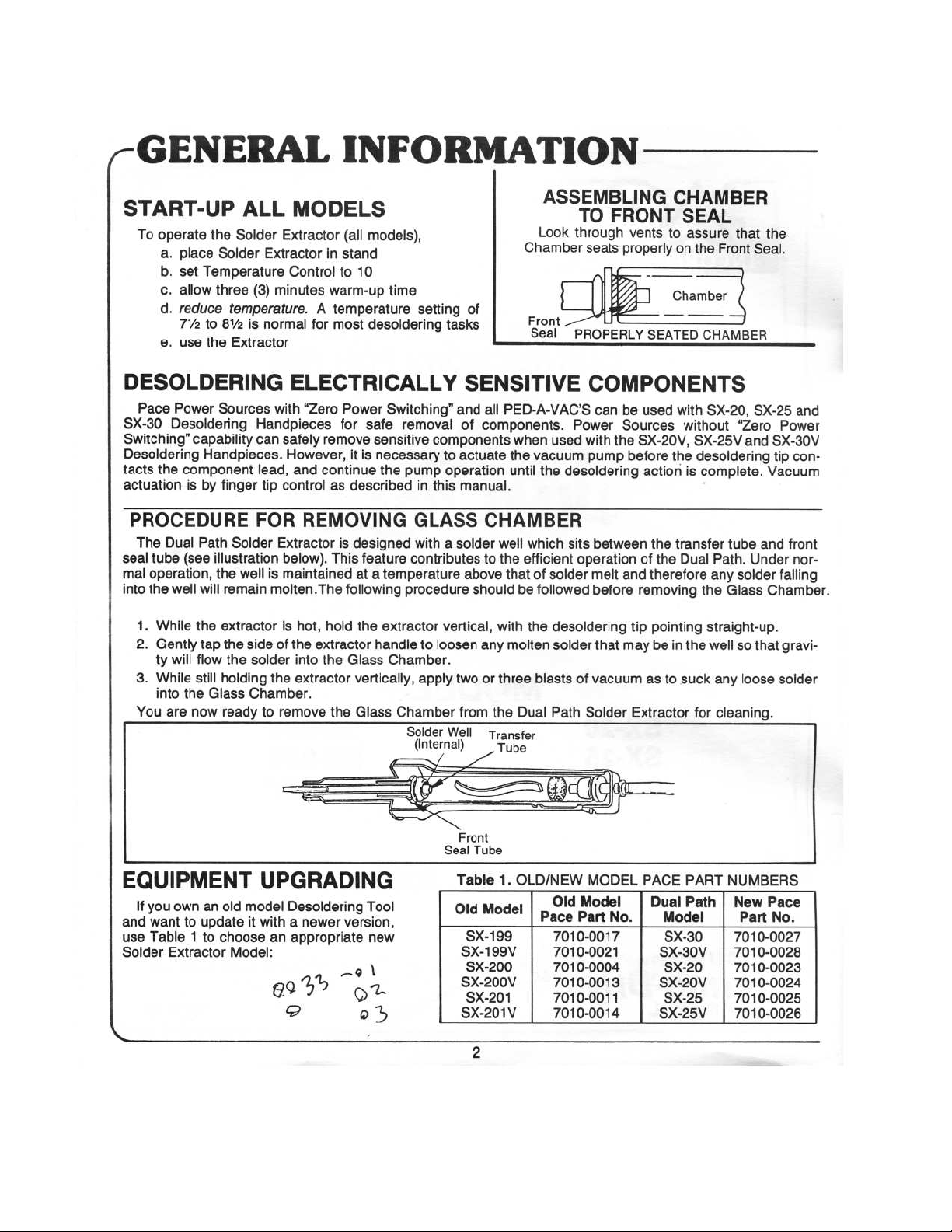
PROCEDURE
The
Dual
seal
tube
mal
operation,
into
the
well
1.
While
2.
Gently
ty
will
3.
While
into
You
are
Sources
capability
Handpieces.
component
is
by
finger
Path
(see
the
Solder
illustration
the
well
will
remain
the
extractor
tap
the
flow
the
still
holding
Glass
now
ready
ALL
Extractor
Extractor
(3)
minutes
is
normal
MODELS
(all
in
stand
Control
to
warm-up
for
most
models),
10
desoldering
ELECTRICALLY
with
“Zero
Handpieces
can
safely
However,
lead,
and
tip
control
FOR
Extractor
below).
is
maintained
molten.
is
side
of
the
solder
into
the
extractor
Chamber.
to
remove
Power
for
remove
it
continue
as
described
REMOVING
is
designed
This
at a
The
following
hot,
hold
the
extractor
the
Glass
vertically,
the
Glass
safe
sensitive
is
necessary
the
feature
temperature
extractor
handle
time
setting
tasks
Switching”
removal
components
to
pump
operation
in
this
GLASS
with a solder
contributes
procedure
vertical,
to
Chamber.
loosen
apply
Chamber
Solder
(Internal)
Well
ASSEMBLING
Look
Chamber
of
Front
Seal
SENSITIVE
and
all
PED-A-VAC’S
of
components.
actuate
manual.
above
two
from
when
the
until
CHAMBER
well
to
the
that
should
be
with
any
molten
or
three
the
Dual
Transfer
Tube
vacuum
the
which
efficient
of
followed
the
blasts
TO
FRONT
through
seats
_PROPERLY
COMPONENTS
can
Power
used
with
the
pump
desoldering
sits
between
operation
solder
melt
before
desoldering
solder
that
of
vacuum
Path
Solder
vents
properly
7
SEATED
be
used
Sources
SX-20V,
before
action
the
of
the
and
therefore
removing
tip
pointing
may
be
as
Extractor
CHAMBER
SEAL
to
assure
on
the
Chamber
ーー
CHAMBER
with
SX-20,
without
SX-25V
the
desoldering
is
complete.
transfer
Dual
Path.
any
the
straight-up.
in
the
well
to
suck
any
for
that
Seal.
SX-25
“Zero
and
tube
Under
solder
Glass
so
that
loose
the
SX-30V
tip
Vacuum
and
Chamber.
Front
cleaning.
and
Power
con-
front
nor-
falling
gravi-
solder
EQUIPMENT
If
you
own
an
and
want
to
use
Table 1 to
Solder
=
update
Extractor
old
model
it
choose
Model:
UPGRADING
Desoldering
with a newer
an
appropriate
8º
25
o
i
Tool
version,
new
ei
a
©
od
Front
Seal
Table
Old
SX-199V
SX-200V
SX-201V
Tube
1.
Model
SX-199
SX-200
SX-201
2
OLD/NEW MODEL
Old
Model
Pace
Part
7010-0017
7010-0021
7010-0004
7010-0013
7010-0011
7010-0014
No. | Model
PACE
PART
NUMBERS
Dual Path | New
Part
SX-30
SX-30V | 7010-0028
SX-20
SX-20V | 7010-0024
SX-25
SX-25V | 7010-0026
7010-0027
7010-0023
7010-0025
Pace
No.
Page 3
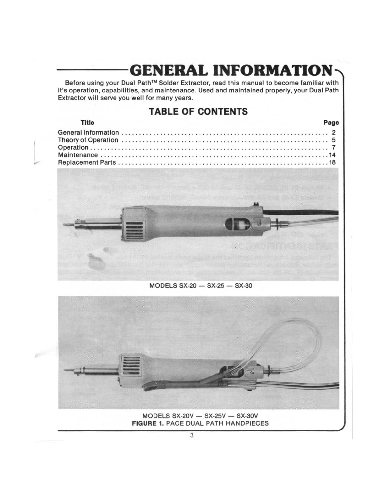
Before
it’s
operation,
Extractor
using
your Dual
capabilities,
will
serve
GENERAL
you
Path™
well
Solder
and
maintenance.
for
many
Extractor,
years.
INFORMATION
read
this
Used
and
maintained
manual
to
properly,
become
familiar
your
Dual Path
>
with
TABLE
Title
Generalinformation.................................
Theory
ОрегаНоп.........
Maintenance
Replacement
of
Operation
...
Parts
上
ユー
ユー・ に に に に に に に に に に
еее
MODELS
OF
CONTENTS
トト
トト
еее
SX-20 — SX-25 — SX-30
トト
トト に トト
トレ
eee
トト レレ
еее
トト
トト
トレ
トト
トレ
トト
ーーー
наенннннь
Page
2
て
5
7
14
MODELS
FIGURE
SX-20V — SX-25V — SX-30V
1.
PACE
DUAL
3
PATH
HANDPIECES
Page 4
(C
GENERAL
INTRODUCTION
INFORMATION
Pace,
non-destructive
describes
Dual Path
Sources.
quired
Inc.
is
six
available
Solder
They
can
outputs.
continuously
rework,
Extractor
be
SPECIFICATIONS
All
Dual Path
60
watt
heat
+
Models
®
Models
»
VisiFilter—is
«
Accessories—
models.
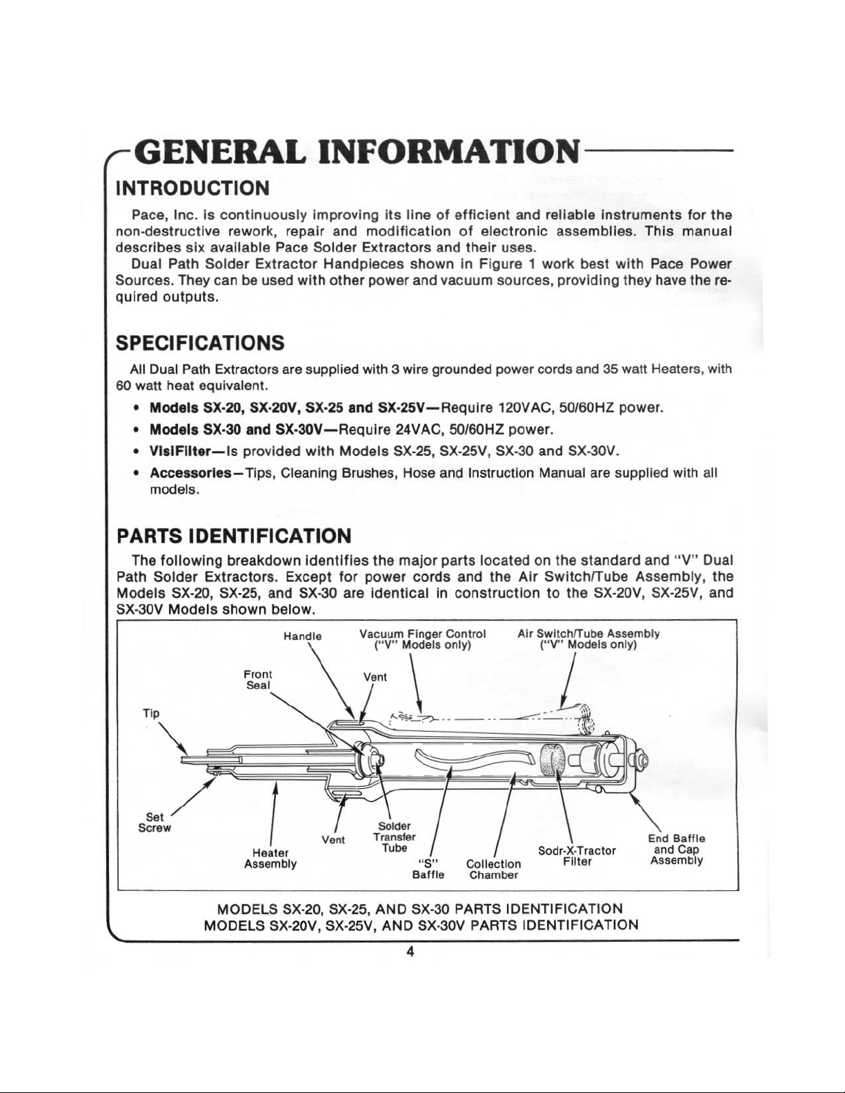
PARTS
The
following
Path
Solder
Models
SX-30V
Models
SX-20,
Extractors
equivalent.
SX-20,
SX-30
SX-20V,
and
provided
Tips,
IDENTIFICATION
breakdown
Extractors.
SX-25,
shown
improving
repair
Pace
used
are
SX-30V—Require
Cleaning
Except
and
below.
Handle
and
Solder
Handpieces
with
other
supplied
SX-25
with
identifies
SX-30
its
modification
Extractors
power
with 3 wire
and
SX-25V—Require
Models
Brushes,
for
are
SX-25,
the
power
identical
Vacuum
(“V"
line
shown
and
grounded
24VAC,
Hose
major
cords
Finger
Models
of
efficient
of
electronic
and
their
in
Figure 1 work
vacuum
50/60HZ
SX-25V,
and
Instruction
parts
located
and
the
in
construction
Control
only)
and
uses.
sources,
power
SX-30
cords and
120VAC,
power.
and
Manual
on
Air
Air
Switch/Tube
(“V"
Switch/Tube
reliable
assemblies.
best
providing
50/60HZ
SX-30V.
are
the
standard
to
the
SX-20V,
Models
instruments
This
with
Pace
they
have
35
watt
Heaters,
power.
supplied
Assembly
only)
with
and
Assembly,
SX-25V,
for
manual
Power
the
“V”
the
re-
with
all
Dual
the
and
Front
Seal
Tip
VA
Set
Screw
Heater
Assembly
MODELS
C
MODELS
SX-20, SX-25,
SX-20V, SX-25V,
Vent
Vent
o
A
E
Solder
Transfer
Tube
"s"
Baffle
AND
SX-30
AND
SX-30V
4
Collection
Chamber
PARTS
PARTS
Sodr-X-Tractor
Filter
IDENTIFICATION
IDENTIFICATION
End
Baffle
Cap
and
Assembly
Page 5
THEORY
OF
OPERATIONS,
DUAL
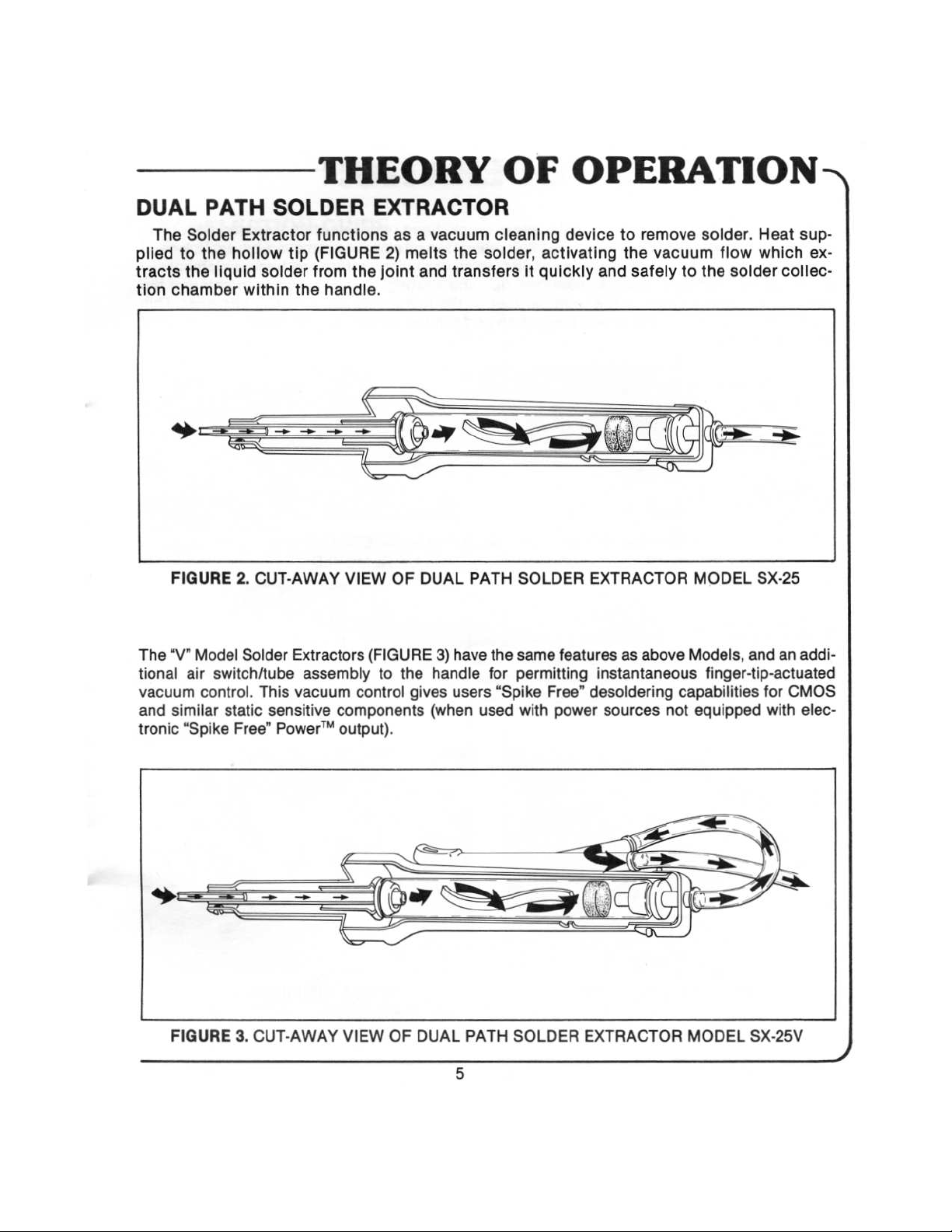
The
Solder
plied
to
tracts
tion
the
chamber
==
FIGURE
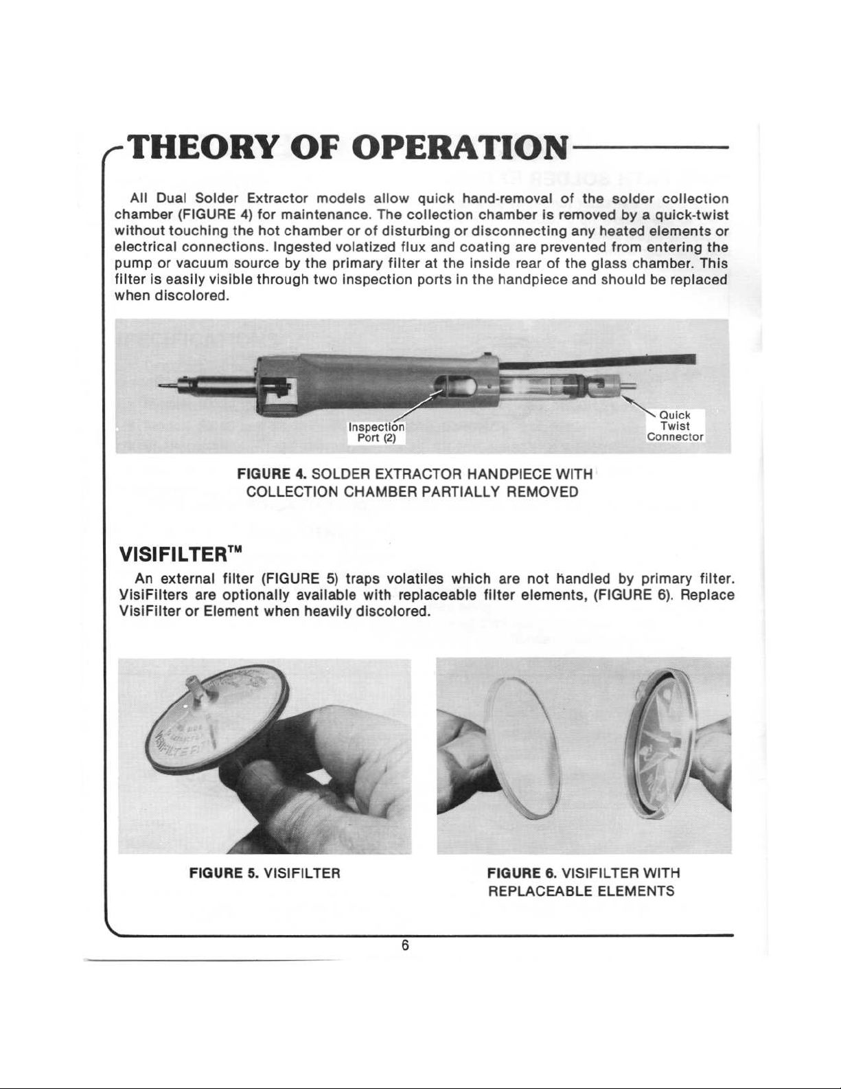
The
“V”
tional
vacuum
and
tronic
air
similar
“Spike
PATH
Extractor
the
hollow
liquid
within
2.
CUT-AWAY
Model
Solder
switch/tube
control.
This
static
Free”
SOLDER
functions
tip
(FIGURE
solder
from
the
Extractors
assembly
vacuum
sensitive
Power™
EXTRACTOR
the
joint
handle.
VIEW
(FIGURE
to
control
components
output).
as a vacuum
2)
melts
OF
the
and
DUAL
3)
handle
gives
(when
the
transfers
have
users
cleaning
solder,
PATH
the
for
“Spike
used
device
activating
it
quickly and
SOLDER
same
features
permitting
Free”
with
power
to
remove
the
vacuum
safely
=
EXTRACTOR
as
above
instantaneous
desoldering
sources
capabilities
not
solder.
to
the
MODEL
Models,
finger-tip-actuated
equipped
flow
solder
and
Heat
which
collec-
SX-25
an
for
CMOS
with
sup-
addi-
elec-
ex-
FIGURE
3.
CUT-AWAY
VIEW
OF
DUAL
PATH
5
SOLDER
EXTRACTOR
MODEL
SX-25V
_)
Page 6
THEORY
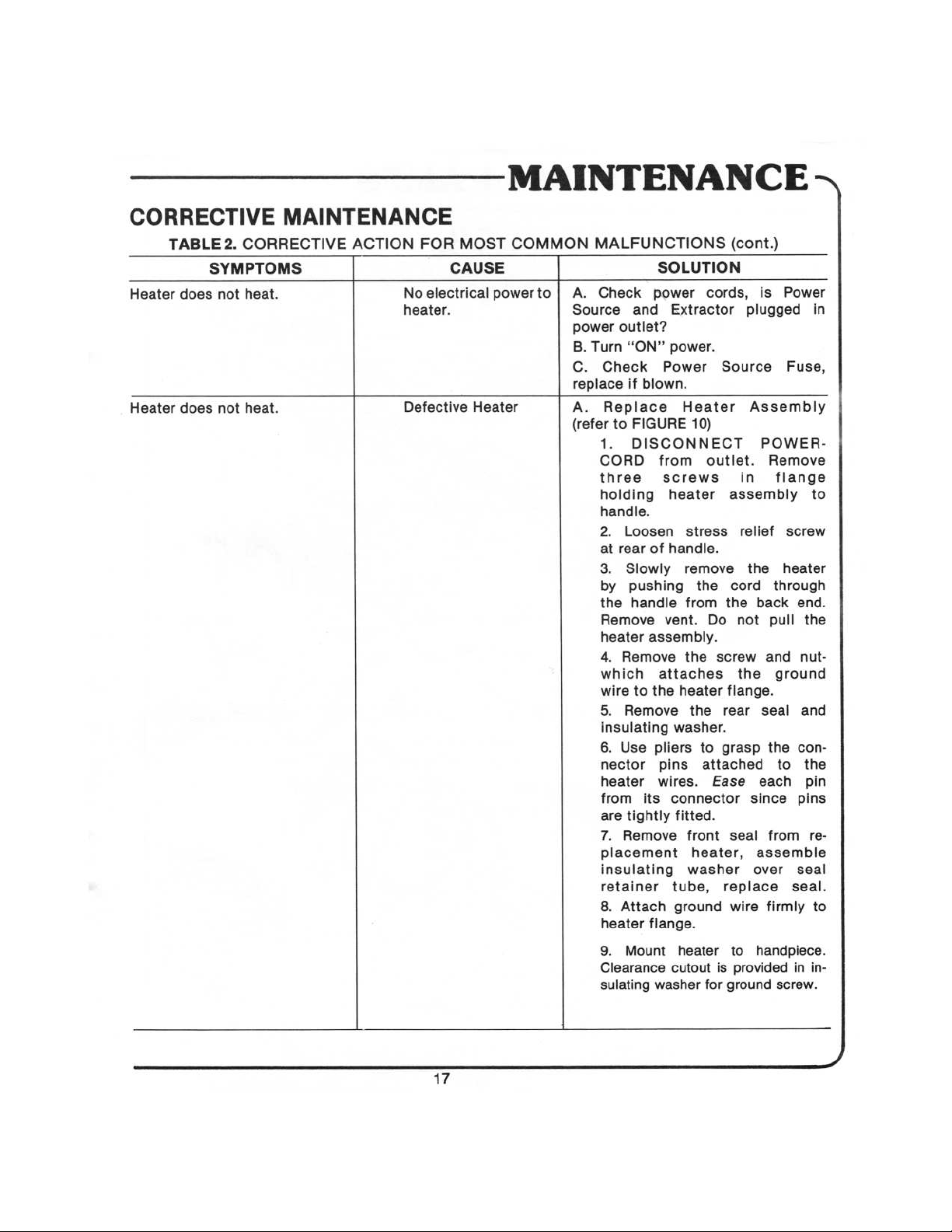
All
Dual
Solder
chamber
without
electrical
pump
filter
when
(FIGURE
touching
connections.
or
vacuum
is
easily
discolored.
visible
Extractor
4)
for
the hot
source
through
OF
models
maintenance.
chamber
Ingested
by
the
two
primary
volatized
OPERATION
allow
The
or of
inspection
guick
collection
disturbing
flux
and
filter
at
the
ports
hand-removal
chamber
or
disconnecting
coating
inside
in
the
is
are
prevented
rear
of
handpiece
of
the
removed
any
the
glass
and
solder
by a guick-twist
heated
from
should
collection
elements
entering
chamber.
be
replaced
or
the
This
FIGURE
VISIFILTER'"
An
external
VisiFilters
VisiFilter
are
or
Element
filter
optionally
4.
COLLECTION
(FIGURE
available
when
heavily
Inspection
Port
SOLDER
5)
EXTRACTOR
CHAMBER
traps volatiles
with
discolored.
(2)
PARTIALLY
replaceable
HANDPIECE
which
filter
REMOVED
are not
elements,
WITH
handled
(FIGURE
RS
by
Quick
Twist
Connector
primary
6).
Replace
filter.
FIGURE
5.
VISIFILTER
FIGURE
REPLACEABLE
6.
VISIFILTER
WITH
ELEMENTS
Page 7

TIP
size
SELECTION
One
of
the
of
Tip
for
most
the
GUIDE
important
job.
Keep
|
Clearance
aspects
several
for
successful
points
in
mind
solder
while
OPERATION
extraction
selecting
is
the
the
selection
Tips:
of
the
~
proper
STEP
1.
enough
and
STEP
leads,
The
to
molten
3.
Match
larger
Extractor
Tip
Inside
fit
loosely
solder
the Tip
Tips
for
%
(952cm)
Diameter
over
flow.
inch
(1.D.)
lead
to
to
the
work.
heavier
leads.
of
the Tip
provide
Small
must
clearance
I.D.
Tips
Assembly
be large
for
air
for
small
Heater
STEP
2.
The
than
pad
while
4.
For
use
Tool
에:
Tip
Outside
the
desoldering
largest
smaller
copper
STEP
removal,
Tip
Screwdriver
Extractor
NM
Diameter
pad
diameter
preventing
I.D.
(0.D.)
to
contact
terminals
Tip
available.
of
the
permit
contact
with
the
and
us,
Tip
must
with
base
material.
solder
splash
Heater
be
the
STEP
5.
Adjust
the
Ye
inch
desoldering
(952cm)
tasks.
selected
beyond
Tip
the
heater
to
extend
body
approximately
for
all
normal
STEP
6.
Tighten
screw
contacts
retaining
Tip.
DO
screw
approximately
NOT
overtighten.
Ya
turn
after
Page 8

OPERATION
SET-UP
STEP
1.Attach
handpiece.
vacuum
hose
to
SX-20/SX-25/SX-30
STEP
2.
shown.
cluded.
Attach
Assemble
hoses
the
to
the
“V"
separate
Model
12”
handpiece
piece
of
hose
as
in-
STEP
3.
Attach
hose
to
STEP
5.
Select
and
Refer
to
Tip
outlet.
Model
X
Model
SX-30
attach
Selection
SX-25
uses
24VAC
Guide
uses
uret
cord
with
the
tip
(page
120VAC
50-60
retainer
with a screw
14).
50-60HZ
HZ
supply.
clamps.
driver.
supply;
STEP
4.
handpiece.
and
SX-20(V)
Attach
Connect
VisiFilter.
models.
STEP
6.
maximum
are
STEP
without
Attach
vacuum
available
8.
Solder
removing
to
VisiFilter
NOTE:
αι
air/vacuum
fit
with
short
VisiFilter
ad
available.
all
Pace
Extractor
heater
assembly
hose
hose
Optional
Power
vents
raised
between
is
to
Sources.
lettering
Power
not
used
Power
air
hose
may
be
towards
Source
with
LA
Source.
fittings
replaced
the
Use
Page 9

INITIAL
To
operate
START-UP
the
Solder
a.
place
Solder
b.
set
Temperature
c.
allow
three
d.
reduce
desoldering
e.
use
temperature. A temperature
the
Extractor
ALL
Extractor
Extractor
Control
(3)
minutes
tasks
MODELS
(all
models),
in
stand
to
warm-up
10
time
setting
OPERATION
of
7%
to
8%
is
normal
for
>
most
V-MODEL
To
operate
Extractors:
OPERATION
the
“V”
Model
a.
Hold
the
finger
Vacuum
b.
On
tion
c.
To
orifice.
Tractor
full
d.
After
your
completed,
your
bent,
Control
the
Power
and
actuate
As
tip.
vacuum
extracting
finger
Power
SX-20V,
handpiece
with
the
Bar,
Source,
Maintenance
the
vacuum,
long
as
the
Keep
moving
operation.
the
tip
back
turn
off
Source).
SX-25V
as
you
would
tip
of
the
and
just
turn
Pump
Instructions
slide
your
orifice
solder,
off
pump.
is
the
component
Continue
remove
the
orifice
See
and
hold a pencil
finger
behind
switch
for
finger
closed,
stirring
the
to
Operation
SX-30V
resting
the
orifice.
to
the
your
tip
firmly
the
vacuum
lead
lead
to
extractor
terminate
Handpiece
(FIGURE
firmly
“ON”
Power
forward
is
actuated
with
the
cool
down
tip
the
and
Maintenance
controlled
7).
on
the
position
Source).
to
Solder
the
from
the
vacuum.
Hold
your
flat
portion
(Refer
completely
through
Extractor
joint.
joint,
to
the
tip
then
(If
operation
instruction
vacuum
index
of
the
Opera-
seal
the
Sodr-X-
during
slide
for
is
FIGURE
7.
CORRECT
POSITION
9
Vacuum
Control
FOR
Bar
HOLDING
THE
HANDPIECE
2)
Page 10

(OPERATION
VACUUM
When
STEP
1.
solder. As
a
film
of
EXTRACTION
performing a desoldering
Position
the Tip
over
the
the
solder
solder
between
melts,
lead
allow
the
solder
and
operation,
making
contact
Tip
to
gently
Tip.
the
with
rest
on
following
STEP
2.
moves
lead
indicates
steps
should
Move
Tip
freely
within
complete
be
followed
with a stirring
the
board
hole.
solder
motion,
Free
melt.
for
best
results.
dwelling
until
movement
lead
of
the
STEP
3.
Apply
ing
vacuum
contact.
STEP
5.
seconds
plete
transfer
vacuum
application.
(NOTE:
Continue
after
removing
of
and
To
Pressure
the
vacuum
Tip
solder
can
from
continue
remove
flow
to
stirring
solder,
damage
one
the
board
Chamber.
action
maintain
or
lift
the pad).
or
two
additional
to
assure
STEP
4.
dur-
light
com-
joint
STEP
thru
Allow
10
Continue
area.
6.
Check
hole
(PTH)
cool
down
stirring
action
your
work.
If
after
between
any
extraction,
resoldering
and
vacuum
solder
remains
resolder
and
extract
and
extraction
flow
to
cool
in a plated-
again
Page 11

OPERATION
>
VACUUM
STEP
7.
of
Hot-air
thru-hole
EXTRACTION
HOT-AIR
pressure
joints.
CLINCHED
PRESSURES.
mode
removes
LEADS
(continued)
solder
from
blind
HOT—AIR
PRESSURES
こき
STEP
8.
Hot-air
jet
mode
melts
planar
solder
connections
and
shrinks
CLINCHED
component
tubing.
LEADS
leads,
STEP
9.
To
melts.
STEP
setting.
for
tract
unclinched
11.
For
solder
Place
complete
solder.
Tip
melt.
Keep
leads,
TERMINALS
extraction
in
contact
Wiggle
wire
wire
moving
place
Tip
on
on
terminals,
with
wire
and
and
apply
during
cool
lead
until
solder
increase
solder.
Watch
vacuum
to
down.
STEP
10.
(WARNING:
in
Move
Steps 3 through
Lift,
heat
ex-
11
STEP
12.
quire
the
System
Solder
application
convenient
or
hot
soldering
Tip
to
end
of
dont
6.
AUXILIARY
extraction
of a second
side.
Use a PACE
lead
pry!).
Extract
HEATING
on
heat
iron
tip
and
lift
to
solder
multilayer
source
Conductive
for
auxiliary
straighten.
as
described
boards
at
the
heat.
may
re-
joint
on
Heating
Page 12

OPERATION
PRESSURE
(USE
controlled
OF
The
following
air
Circumstances
solder
Sided
the
flow.
the
The
uses
joint.
Solder
board.
In
this
hole
thus
“Pressure
the
following
MODE
AIR
PRESSURE)
procedures
pressure
This
Joint”
This
case
causing a sweat
Mode”
a.
Connect
to
b.
Place
Cubbies”,
the
outlet.
may
is
most
is
so
is
common
the
vacuum
is
steps:
the
“maximum”.
the
heater
apply
when
occur
when
the
often
the
case
named
now
tip
and
tube.
because
when a terminals
method
joint.
required
air
line
to
of
the
use a burst
the
extractor
Vacuum
when a “Blind-Sided
of
its
is
not
applicable
So
in
this
to
break
up
the
Pressure
Extractor
of
pressure
is
Mode
inaccessibility,
flanged
case
this
Blind-Sided
Flow
into
the
used
of
end
since
(see
control
to
clear
“Solder
with
Power
operation
Solder
usually
(on
opposite
no
cooling
Step 7 on
Solder
valve
Dump”
any
molten
Sources
will
Joint”
on
air
page
Joint.
and
not
completely
is
found.
the
component
side
of
can
11;
and
The
adjust
between
solder
equipped
The
board)
be
pulled
steps
“Pressure
Pressure
the
which
might
with
remove
“Blind-
side
blocks
through
below).
Mode”
control
two
“Hot
be
a
a
of
air
in
c.
Heat
must
Place
the
heated
WARNING—ALLOW
AREA.
d.
When
the
Blind-Sided
vide
continuous
joints
caused
If
conformal
desoldering
(See
hot
ς
coating
operation.
air
jet
page
is
Try
13.)
be
transmitted
tip
burst
by
the
blocking
hot
air jet
through
over
and
THE
TIP
Solder
continuing
air
to
Joint
of
pressure.
flow,
the
decure
12
the
in
contact
TO
COME
is
heated
Stir
flow
of
coating
coatings;
lead
to
melt
with
the
INTO
LIGHT
sufficiently,
the
lead
to
air.
must
be
or
thermo-plating
the
lead.
CONTACT
prevent
removed
Blind-Sided
WITH
actuate
the
reformation
before
tool
to
remove
Solder
THE PAD
airflow
of
the
vacuum
coatings
to
Joint.
pro-
sweat
Page 13

OPERATIONS
HOT
The
+
SURFACE
Surface
ing
AIR
hot
JET
air
solder
steps
a.
b.
c. A carefully-directed
d.
MODE
mode
of
operation
SOLDERED
joints
should
With
Source,
solder.
Reduce
approximately
lead
you
Repeat
the
If
desirable
prior
be
taken
the
air
set
the
with a soldering
might
component
surface
to
lift
this
joints
to
using
are
line
Pressure
Pressure
process
is
JOINTS
removed
for
connected
Ys”
the
pads
is
free.
are
use
the
Hot
Air
used
the
valve
valve
Hot
from
aid
from
for
GENERAL
heavily
Vacuum
Jet
for
several
with
the
“Hot
succesful
to
the
and
power
setting
Air
Jet
will
the
surface.
or
tweezer.
the
each
individual
mounded
Mode
Method.
different
Air
Jet
removal
Pressure
to
“MAX”
to
“MIN”
melt
the
When
Do
not
substrate.
lead
NOTE
with
to
remove
applications:
Mode”
of
surface
Flow
Control
and
and
use
solder
you see
lift
until
solder,
joint
before
all
it
excess
of
operation.
mounted
Valve
blow
out
.036
1.D.
when
the
solder
melting
leads
may
be
solder
The
components.
on the
excess
Tip.
the
tip
melt,
is
observed,
are
removed
follow-
Power
molten
is
held
lift
the
or
and
¢
HEAT
To
use Hot
jet
slowly
evenly
allowing
¢
CONFORMAL
Apply
with
*
REMOVAL
Apply
material.
be
required
thickness
SHRINKABLE
Air
along
distribute
it
to
cool.
Hot
Air
Jet
an
orange
OF
Hot
Air
Jet
Then
for 2 or 3 minutes,
of
the
TUBING
Jet
Mode
the
entire
heat
COATING
to
the
stick
so
BONDED
to
the
twist
the
coating.
of
Operation
length
to
shrink
REMOVAL
conformal
you
won't
COMPONENTS
component
component
of
the
tubing.
(Epoxy
coating
damage
body
to
depending
for
shrinking
tubing.
Be
sure
to
and
be
removed
13
tubing,
Do
not
all
tubing
and
Polyurethane)
be
removed.
the
board.
surrounding
with
upon
the
apply
play
the
has
Remove
pliers
size
hot
shrunk
area
or
of
the
the
properly
air
at
completely
the
softened
to
soften
tweezers.
component
one
point,
the
Heating
adjusted
but
before
coating
bonding
may
and
the
Page 14

„MAINTENANCE
TIP
CARE
The
Extractor
following
*
Remove
a
non-contaminating
+
The
during
in
the
*
Charred
the
suggestions
Solder
tip
Tips
should
will
excess
normal
heater
coating
with a length
solder,
Extractor
use.
assembly.
of
prevent
material.
Tip
The
flux
of
be
cared
burned
is
expendable;
Tip
must
can
cause
small-diameter
for
damage
flux,
and
be
replaced
blockage
in
the
to
the
conformal
washout
stiff
same
handpiece
before
in
the
tip
wire.
manner
coatings
(thinning)
it
becomes
bore.
as
assembly:
by
Clear
soldering
lightly
of
the
so
thin
the
iron
wiping
inside
that
residue
tips.
the
bore
it
breaks
from
The
tip
on
occurs
off
inside
BROKEN
If
the
tip
steel
rod,
while
the
front
face
TIP
breaks
slightly
Extractor
of
the
less
heater
REMOVAL
off
in
the
Heater
than
1/8
is
still
hot.
is
supported
inch
With
assembly,
in
diameter,
set
screw
and
drive
remove
to
ram
removed,
the
broken
power
the
insert
tip
cord
broken
ram
out.
from
power
tip
out
from
handle
(FIGURE
of
source.
the
Heater
end
8)
Use
tube
while
a
the
FIGURE
8.
BROKEN
14
TIP
REMOVAL
Page 15

TIP
REPLACEMENT
a.
While
the
.
Remove
.
Clean
.
Place
.
Tighten
200
Although
that
the
once
every
SOLDER
buildup
with a large
and
CLEANING
Solder
often
inside
and
as
necessary
of
Chamber
flux
unit
the Tip
Heater
new
Tip
set
screw
set
screw
“S”
PROCEDURE
is
idling
hot,
loosen
from
the
Heater.
with
small
wire
brush
in
Heater
screws
be
eight
operating
COLLECTION
in
Chamber
bristle
Baffle.
1/8
turn
are
loosened
with
hangout
past
the
NOTE
permanently
and
hours.
depends
brush.
Apply mineral
MAINTENANCE.
set
screw
to
free
the
tip.
to
remove
of
point
lubricated,
the
CHAMBER
upon
1%
of
tip
use.
oxide
to
%.
contact
be
removed
Clean
oil
buildup.
to
secure
it
is
essential
at
Chamber
to
the
brush
Tip
least
and
in
“S”
and
place.
Baffle
lightly
as
coat
REPLACING
The
white,
(FIGURE
very
restriction,
9)
should
important
and
PRIMARY
primary
be
that
this
keeps
Sodr-X-Tractor
changed
filter
contaminants
VISIBLE
whenever
be
kept
FIGURE
9.
SODR-X-TRACTOR
FILTER
Filter
clean;
from
Sodr-X-Tractor
located
heavy
this
reaching
Filter
deposits
assures
within
of
optimum
the
vacuum
FILTER
the
rear
of
contaminants
air
flow
source.
Rear
Seal
LOCATION.
the
Glass
are
noticeable.
and
minimum
Baffle
End
Cap
Assembly
and
Chamber
It
flow
is
15
Page 16

(MAINTENANCE
CORRECTIVE
Table
tion
The
joints
removed
(2)
outlines
to
each:
TABLE
SYMPTOMS
operator
are not
on a consistent
notices
MAINTENANCE
the
most
2.
CORRECTIVE
that
solder
being
completely
basis.
common
ACTION
Loss
deficiencies
FOR
CAUSE
of
Vacuum
MOST
which
might
COMMON
A.
wire
C.
a
Transfer
THE
occur
MALFUNCTIONS
Clean
Tip
B.
Clean
bristle
Check
has shifted
position
Tube,
reduced.
Baffle
maintains a constant
Chamber.
bending
fingers.
GLASS
be
Baffle
room
9).
D.
is
Е.
contaminant
air
F.
air
of
replace
G.
or filter
Dark
replacement.
H.
Vacuum
“Operation
Source
manual.
It
have
the
DO
“S”
BAFFLE
CHAMBER.
seated
Assembly,
for
Front
Seal—Assure
properly
Sodr-X-Tractor
flow.
Replace.
Damaged
hose
can
vacuum.
if
Clogged
element
discoloration
Clogged,
Transducer—Refer
or
SOLUTION
Heater
brush.
“S”
within
is
enough
This
“S"
NOT
just
the
seated
necessary.
VisiFilter—Replace
and
the
bore.
solder
Baffle.
where
Filter
loaded
Air
cause
Vacuum
If
the
it
the
vacuum
important
tension
may
be
Baffle
ATTEMPT
WHILE
The
in
front
leaving
(refer
on the front
Visible
filter
Hose—A
partial
Examine
when
indicates
Damaged
Maintenance
easiest
transfer
the
Glass
that the
position
between
Baffle
of
that
filter
Transducer”
solu-
“S”
Baffle
Tube
blocks
could
so that
in
adjusted
TO
BEND
IT IS
IN
should
the
End
sufficient
to
FIGURE
Chamber
seal.
Filter—A
will
reduce
damaged
or
full
hose
is
loaded.
time
Pump
to
Power
with
to
the
be
“S"
it
the
by
your
THE
Cap
loss
and
filter
for
or
your
16
Page 17
MAINTENANCE
~
CORRECTIVE
Heater
Heater
TABLE
SYMPTOMS
does
does
not
2.
not
MAINTENANCE
CORRECTIVE
heat.
heat.
ACTION
No
heater.
FOR
CAUSE
electrical
Defective
MOST
COMMON
powerto | A.
Heater
MALFUNCTIONS
Check
Source
power
B.
C.
replace
A.
(refer
and
outlet?
Turn
“ON”
Check
if
blown.
Replace
to
FIGURE
1.
DISCONNECT
CORD
three
holding
handle.
2.
Loosen
at
rear
3.
Slowly
by
pushing
the
handle
Remove
heater
4.
Remove
which
wire
to
5.
Remove
insulating
6.
Use
nector
heater
from
its
are
tightly
7.
Remove
placement
insulating
retainer
8.
Attach
heater
of
assembly.
flange.
SOLUTION
power
attaches
the
pliers
wires.
cords,
Extractor
power.
Power
Heater
10)
from
pins
outlet.
screws
heater
stress
handle.
remove
the
from
vent.
Do
the
heater
the rear
washer.
to
attached
Ease
connector
fitted.
front seal
heater,
washer
tube,
ground
(cont.)
plugged
Source
Assembly
in
assembly
relief
the
cord
the
not
screw
the
flange.
grasp
since
over
replace
wire
is
Power
Fuse,
POWER-
Remove
flange
screw
heater
through
back
end.
pull
and
ground
seal
the
con-
to
each
pins
from
assemble
seal
seal.
firmly
in
to
the
nut-
and
the
pin
re-
to
9.
Mount
Clearance
sulating
heater
cutout
washer
is
for
to
handpiece.
provided
ground
in
screw.
in-
17
Page 18

REPLACEMENT
PARTS
q
FIGURE
10.
DIAGRAM
OF
18
REPLACEMENT
PARTS
Page 19

ITEM
20
22
23
30
TABLE
1
1A
2
2A
3
4
5
6
7
8
9
10
11
12
13
14
15
16
17
18
19
21
24
25
26
27
28
29
31
3.
NO.
REPLACEMENT
LIST
OF
REPLACEMENT
(Refer
Extractor
Extractor
Vents
Vent
Super
Glass
“S”
Sodr-X-Tractor
Heater
Heater
Heater
Screw,
Screw
Set
Nut
Line
Line
Line
VisiFilter
VisiFilter,
Filter
Twist
Tubing
Tubing
Tubing
Clamp,
Clamp,
Tubing,
Baffle
Bristle
Wire
Cushion
Front
Rear
Handle,
Handle, SX-20V,
(2)
(1)
Tip
Chamber
Baffle
and
Seal
and
Seal
Washer
Nylon 1405-0341
w/Lockwasher
Screw
(Pk/10)
#4-40,
Hex
Cord
Assembly
Cord
Assembly,
Cord
Assembly
Replaceable
Element,
Lock
Fitting
Assembly
Assembly
12”
Flat
Round
6°
Length
and
End
Brush
Brush
Grip
Seal
Seal
to
SX-20, SX-25,
Filter
Assembly,
Assembly,
Head
VisiFilter
w/VisiFilter
w/Twist
Cord
Type
Cord
Cap
(fits
standard
FIGURE
DESCRIPTION
SX-25V,
(Pk/10)
Dual Path
Dual Path
#4-40 x 5/16”
(1)
(VDE)
Standard
(24VAC)
Element
Lock
Type
Assembly,
handpiece
PARTS
10
SX-30
(120VAC)
Type
Fitting
Dual Path
for
SX-30V
120VAC,35W
24VAC,35W
SST
(4)
only)
FOR
Item
SOLDER
No.)
PARTS.
EXTRACTOR
PACE
PART
NO.
1119-0039
1119-0050
1119-0041
1119-0042
See
Tip
Chart
1265-0003
4010-0033
1309-0018
6010-0034
6010-0035
1213-0030
1348-0285
1332-0090
1332-0009
1332-0032
1309-0020
1309-0028
1309-0027
1263-0004
1325-0017
1325-0006
1342-0001
1211-0002
1321-0085-02
1325-0003
4010-0071
1127-0002
1127-0006
1346-0042
1213-0033
1213-0001
REPLACEMENT
Table 4 lists
the
Outside
Diameter
Inside
(1.D.)
replacement
Diameter
Nom.
TIPS
Tips
(O.D.)
and
TABLE
FIGURE
SUPER
TIPS
Outside
4.
REPLACEMENT
1.D.
(0.D.)
+
11.
FOR
in. | mm
018 | 0.45
.025 | 0.63
036 | 0.91
050 | 1.27
061
.095 | 2.43
Diameter
Ref.
MEASUREMENT
SOLDER
used
for
the
Inside
Diameter
NOMINAL | O.D.
1.55 .104
19
EXTRACTOR
Solder
in.
059
.060 1.52
072
„085
125
Extractor.
(I.D.),
PART
REFERENCE | PACE PART
OF
then
NUMBER
mm
1.34
1.83
2.16
2.64
3.17
REPLACEMENT
Use
select
FOR
NUMBER
1121-0213
1121-0214
1121-0215
1121-0216
1121-0217
1121-0091
FIGURE
the
Tip
TIPS
Super
have
1.D.
marks
(Trademark)
TIPS
11 to
part
tips
two
determine
from
Table
4.
ノ
Page 20

|
INCORPORATED
|
LAUREL,
©1982 PACE
ALL
SPECIFICATIONS
9893
MARYLAND
(301)
FAX
INCORPORATED
SUBJECT
490-9860
301
ALL
TO
498
RIGHTS
COURT
20723-1990
3252
RESERVED
CHANGE
WITHOUT
a
USA
PRINTED
NOTICE
IN
U.S.A.
 Loading...