

Page 1
DTP-80
DTP-80 Dual ThermoPik Handpiece
OPERATION & MAINTENANCE MANUAL
Page 2

2
PACE Incorporated retains the right to make changes to specifications contained
herein at any time, without notice.
Contact your local authorized PACE Distributor or PACE Incorporated to obtain the
latest specifications.
The following are registered trademarks and/or servicemarks of PACE Incorporated,
Laurel Maryland U.S.A. and may only be used to identify genuine PACE products or
services:
AdapTip, Arm-Evac, Cir-Kit, ComForm I, ConducTweez, CRAFT,
Dual Path, Flo-D-Sodr, FuseSet, HandiPik, HotSpot, LapFlo, MBT,
Micro Portable, MicroChine, MiniChine, Mini-Wave, PACE, Pacenter,
Ped-A-Vac, PETS, Pik-Vac, PRC, PRINT, Pro-Evac, Redi-Rak,
ResisTweez, SensaTemp, SMR, Snap-Vac, Sodr-Pen, Sodr-X-Tractor,
SR-3, SR-4, ST, StripTweez, SwaPlater, ThermoBand, Thermo-Drive,
ThermoJet, ThermoPart, ThermoPik, ThermoTweez, Tip-Evac, VisiFilter.
The following are trademarks and/or servicemarks of PACE Incorporated, Laurel
Maryland U.S.A. and may only be used to identify genuine PACE products or
services:
Auto Off, Cubby-Vac, Datastore, Dust Evac, EKO, Lab Evac, MicroSpin,
PaceLink, PaceNet, Pik & Paste, Prep-Set, Pulse Plate, Spa-Kleen,
ThermoBond, TinSpin, TweezPik, Uni-Frame, V-A-N, Ventur-Evac.
Since 1958, PACE Incorporated has provided advanced technology
training in all aspects of hand soldering, rework and repair.
Additional copies of this manual or other PACE literature may be obtained from:
PACE Incorporated (301) 490 - 9860
Sales Administration (301) 498 - 3252 Fax
9893 Brewers Court
Laurel MD 20723-1990
© 1995 PACE Incorporated, Laurel MD. All rights reserved. Printed in the U.S.A.
Page 3

3
DTP-80
DUAL THERMOPIK HANDPIECE
PACE P/N 7029-0001
OPERATION & MAINTENANCE
MANUAL
MANUAL NUMBER 5050-0403
REV. A
For any questions regarding the following instructions, contact your local authorized
PACE dealer or contact PACE directly at:
Telephone (301) 490-9860, Fax (301) 604-8782
PACE Incorporated
9893 Brewers Court
Laurel MD 20723-1990
Page 4

4
These instructions detail the basic operational guidelines for using the DTP-80 Dual
ThermoPik handpiece.
INTRODUCTION
The DTP-80 Dual ThermoPik handpiece provides safe, one-handed removal of a
wide variety of Quad FlatPacks (PQFPs) in a matter of seconds and can even remove
BGAs (Ball Grid Arrays). The Dual ThermoPik is a member of the PACE
SensaTemp family of advanced handpieces.
CAUTION
Always return heated handpieces to the appropriate Tip & Tool Stand
when not in use. Failure to do so may cause burns to the operator,
equipment or work surfaces and may be a potential ignition source if
combustible materials are nearby. Always use this handpiece in a well
ventilated area to avoid the inhalation of fumes created by solder flux
gases.
Page 5
HANDPIECE SETUP
HANDPIECE ALIGNMENT
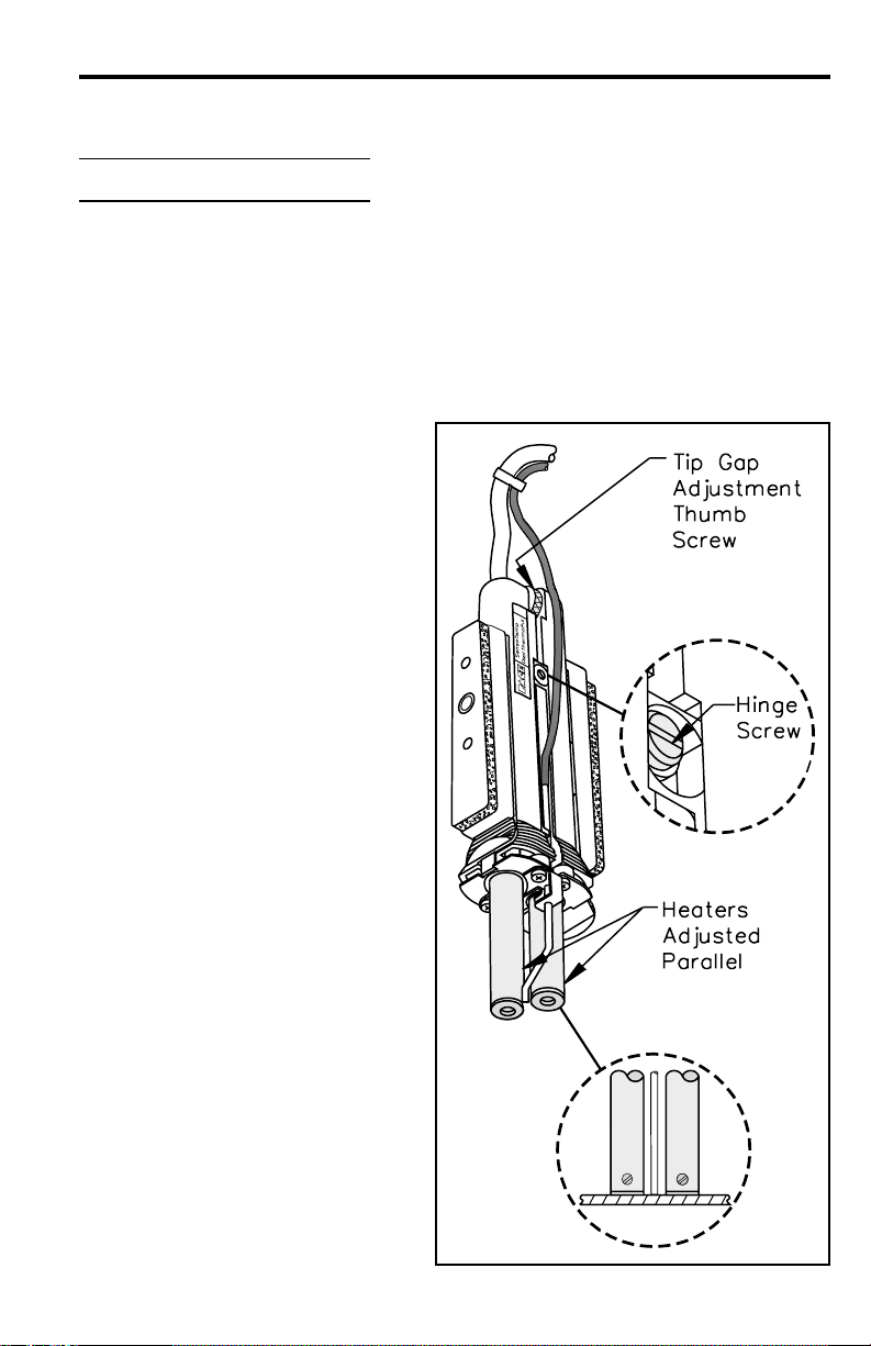
Check the handpiece heaters for proper alignment with each other. Proper handpiece
(and tip) alignment is essential for effective operation.
1. Remove any installed tip.
2. With the handpiece at room
temperature, adjust the
heaters parallel to each other
(refer to illustration) using the
Tip Gap Adjustment Thumb
Screw. If the heater ends are
even with each other, go to
"Power Source Connection".
If the ends are not even, go to
step 3.
3. Loosen the handpiece Hinge
Screw 1/2 turn.
4. Holding the handpiece in a
vertical position (heaters
facing down), place the ends
of the two heaters against a
hard flat surface to insure
proper alignment. The heater
ends should be even with each
other and flush against the flat
surface. Gently push the rear
of the handpiece handles to
force both heaters against the
flat surface.
5. Tighten Hinge Screw to secure
in position.
5
Page 6

6
POWER SOURCE CONNECTION
NOTE
If using your DTP-80 ThermoPik for the first time or if you have just
replaced the heater, you must follow the “DTP-80 Heater Burn-in”
procedure (red tag on handpiece) to increase the life expectancy of the
heater and to minimize any smoke and fumes generated by the heater on
its initial power-up.
Connect the handpiece power cable connector to one of the front panel power
receptacles on your PACE power source. PACE recommends that air handpieces
utilize the power receptacles closest to the AUTO SNAP-VAC (or SNAP-VAC) Port
to minimize cord tangles.
NOTE
To insure optimum performance, use only one Dual ThermoPik
handpiece and any other SensaTemp handpiece (except TT-65
ThermoTweez) on 2 channel power sources. On MBT 250A/220A or
PRC 2000 systems, use of 2 Dual ThermoPiks or a Dual ThermoPik
and a ThermoTweez handpiece may be powered by the same power
source with the third channel left vacant (no handpiece connected).
Page 7

7
TIP TEMPERATURE
The DTP-80 rapidly transfers heat by contact and typically allows component
removal at relatively low temperatures in the 288 - 343°C (550 - 650°F) range. Tip
temperature and removal times will vary with each application. PACE recommends
the use of a 316°C (600°F) tip temperature setting for initial use in any particular
application. With practice, many components can be removed at lower
temperatures. Use the lowest possible tip temperature that will provide rapid, yet
controlled solder reflow. Lower temperatures extend tip and heater life, allow solder
to remain on the lower surfaces of the tip (to improve thermal linkage between the
tip and the component during component removal) and help prevent possible board
damage.
Refer to the Tip & Temperature Selection System booklet for your particular
handpiece/tip combination. For all Dial Display SensaTemp systems, the booklet
will indicate the correct Dial Settings for the True Tip Temperature. On systems
incorporating a Digital Readout, set the desired operating temperature and Tip Offset
Constant for the DTP-80 handpiece/tip combination into the channel powering the
DTP-80.
Page 8

AIR HOSE CONNECTION
Use the following procedure to attach the handpiece air hose to your PACE power
source.
NOTE
Ensure that only one air hose is connected to the AUTO SNAP-V AC (or
SNAP-VAC) or Controllable PRESSURE Port at one time. Attachment
to both ports simultaneously will cause a deterioration of performance.
To set up your DTP-80 for operation, perform the following steps:
1. Connect the 152 cm (60 inch)
length of black silicone air hose
to the Vacuum Pick tube (metal
tube) in the middle of the
handpiece.
2. Attach the male quick connect
hose mount fitting (P/N 1259-
0102) supplied with the
handpiece to the other end of
the black silicone air hose. This
fitting has a special Vacuum
Release Opening to provide a
quick component release during
component removal operations;
DO NOT use any other male
fitting.
3. Secure the air hose to the
handpiece power cable with
hose clamps (P/N 1321-0274).
8
Page 9

9
4. Prepare a VisiFilter by
connecting a 2.5cm (1 inch)
length of clear pvc air hose to
each side of the VisiFilter.
Connect a female quick
connect hose mount fitting
(P/N 1259-0086) to one of
the air hose ends . Connect
the 152cm (60 inch) length of
black silicone air hose to this
end of the VisiFilter and the
DTP-80 handpiece.
5. To the other air hose end (on VisiFilter), attach a male quick connect hose
mount fitting (P/N 1259-0087).
6. Attach the male quick connect hose mount fitting (on VisiFilter air hose)
to the power source AUTO SNAP-VAC (or SNAP-VAC) Port.
NOTE
Always use your Dual ThermoPik handpiece with a clean VisiFilter
element. Otherwise a deterioration in performance or damage to the unit
may occur.
Page 10

10
TIP SELECTION
Selection of the proper tip is essential for effective operation. Attempts to use an
improperly sized tip will result in unsatisfactory handpiece operation and may result
in lifted lands or board damage.
Table I details a partial listing of available tips. Contact your local authorized PACE
dealer for the latest Tips & Accessories Catalogue which details all available tips
and accessories.
TIP INSTALLATION
The following instructions are for tip installation only. If a tip is currently installed
in the handpiece, remove the installed tip (heater hot) and clean both heater bores
using the supplied 3/16" diameter wire brush prior to the installation of a new tip.
1. Select the proper tip for your application. Refer to Table 1.
2. Insert the tip shafts fully into the heater bores.
3. Using the supplied Tip & Vacuum Cup Tool
(P/N 1100-0239) or small screwdriver,
tighten the heater assembly set screws for a
snug fit. Do not over tighten.
NOTE
The DTP-80 tips must be kept properly tinned and free of oxidation to
maximize tip life. Use the tip cleaning tools to remove all traces of solder
from the heated tip. Carefully inspect for any oxidation buildup. If
oxidation is present, re-tin and clean the tip until no oxidation spots
remain. Immediately tin the tip surfaces and keep them tinned at all times.
Page 11

11
PQFP Removal Tip Descriptio
PQFP 100
PQFP 132
PQFP 144
A
Application
B
PQFP 208
PQFP
160/208
PQFP 240
PQFP 196
PQFP 304
Tip Size
A X B
0.83" x 0.83"
(21.1mm x
21.1mm)
1.03" x 1.03"
(26.2mm x
26.2mm)
1.15" x 1.15"
(29.2mm x
29.2mm)
1.17" x 1.17"
(29.7mm x
29.7mm)
1.21" x 1.21"
(30.7mm x
30.7mm)
1.33" x 1.33"
(33.8mm x
33.8mm)
1.42" x 1.42"
(36.1mm x
36.1mm)
1.67" x 1.67"
(42.4mm x
42.4mm)
Part
Number
1121-0549
1121-0551
1121-0553
1121-0557
1121-0552
1121-0558
1121-0554
1121-0593
BGA Removal Tips
BGA-169
A
B
Application
BGA-225
All dimensions are no minal.
Consult your authorized PACE Distributor for
Table I. Dual ThermoPik Tip Selection Guide
.88" x .88"
(22.4mm x
22.4mm)
1.10" x 1.10"
(27mm x 27mm)
NOTE:
sizes not listed.
1121-0594
1121-0596
Page 12

VACUUM CUP INSTALLATION/REMOVAL
Three vacuum cup sizes are available for use with the DTP-80 handpiece. For
optimum performance, select the largest vacuum cup which is smaller than the body
of the component being removed. Use the supplied Tip & Vacuum Cup Tool and the
following instructions to remove or install the vacuum cup.
WARNING
Do NOT install or remov e a Vacuum Cup with bare hands! Alwa ys use
the Tip & Vacuum Cup Tool! Installation by any other means may cause
burns to the operator.
INSTALLATION
1. Ensure that the proper tip is installed in the
handpiece.
2. Place the selected Vacuum Cup on the Pin of
the Tip & Vacuum Cup Tool as shown.
3. Press the vacuum hose against the
handpiece handle as shown. This will
hold the Vacuum Pick in position.
12
Page 13

4. Insert the Tip & Vacuum Cup
Tool Pin into the end of the
handpiece Vacuum Pick.
5. Gently push the Vacuum Cup
onto the Vacuum Pick.
6. Remove the Tip & Vacuum Cup
Tool.
REMOVAL
1. Place the open-slotted end
of the Tip & Vacuum Cup
Tool around the Vacuum
Pick and behind the Vacuum
Cup as shown.
2. Press the vacuum hose
against the handpiece
handle to hold the Vacuum
Pick in position.
3. Pull the Vacuum Cup off the
end of the Vacuum Pick.
13
Page 14

VACUUM PICK ADJUSTMENT
Proper vacuum must be maintained to lift and hold the component during a removal
operation. The Vacuum Pick Assembly within the DTP-80 handpiece adjusts
quickly and easily to provide an optimum setting where the vacuum cup makes
contact with the component body as the tip makes contact with the component leads.
To adjust the Vacuum Pick Assembly, perform the following procedure:
1. Ensure that the proper tip and vacuum cup are installed on the DTP-80.
2. Using the Tip & Vacuum Cup Tool,
grasp the Vacuum Pick as shown in
the illustration.
3. Adjust the Vacuum Pick position to a
point where the end of the Vacuum
Cup is flush (even) with the bottom
edges of the tip.
IMPORTANT - The Vacuum Pick is now in a proper position for initial operation.
During the first component removal operation, the vacuum cup will contact the
component body as the tip is lowered over the component. As the tip moves down
to contact the component leads, the vacuum pick slides into position. Readjustment
will not be required until the component removal application changes (e.g., different
component, tip, vacuum cup).
14
Page 15

TIP PREPARATION
DTP-80 tips must be kept free of oxidation to ensure that maximum heat transfer
will take place at all times.
BGA Removal Tips - are not tinnable; use the tip cleaning tools (provided with the
optional Tip Maintenance Station P/N 6993-0138) to remove all traces of oxidation
from the heated tip.
PQFP Removal Tips - must be kept properly cleaned and tinned. Carefully inspect
for any oxidation buildup. Use the tip cleaning tools (provided with the optional Tip
Maintenance Station P/N 6993-0138) to remove all traces of oxidation and solder
from the heated tip. If oxidation is present, clean the tip until no oxidation spots
remain. Immediately tin the tip surfaces and keep them tinned at all times.
Prepare the installed tip using the following procedure:
1. Clean all bottom edges of the installed tip using a PACE fiber cleaning
tool.
2. Shock the bottom edges of the installed tip using a PACE sponge tool or
sponge.
3. When using a PQFP Removal Tip, apply
a continuous bead of solder along the
bottom edges of the installed tip.
NOTE
The molten solder of a properly tinned PQFP Removal Tip is the medium
through which an efficient heat transfer takes place making sim ultaneous
reflow of all solder joints and component removal possible.
15
Page 16

BOARD/COMPONENT PREPARATION
Proper preparation is the key to successful component removal. To obtain optimum
results, this procedure should be followed.
Once you become familiar with the use of the handpiece, you may find it beneficial
to develop procedure variations which comply with your company guidelines.
1. Remove any protective coatings and clean the component leads and land
areas using an approved solvent or cleaner.
2. Ensure that the PCB is free of moisture. You may wish to gently dry the
area using a heated air tool ( i.e., TJ-70 ThermoJet).
3. Preheat the PCB as necessary. PCBs consisting of heat sinking materials
(e.g., ceramic, polyamide, etc.) or those with an exceptionally heavy
ground or power planes may require the use of a preheating system such
as the PACE HotSpot.
16
Page 17

4. In order to maximize heat transfer from the handpiece tip to PQFP
component lead/land connections, PACE recommends adding
bridgefill ..............
solder wrap ..........
or
flux ......................
to maximize heat transfer across all connections.
When removing BGA components, the use of flux is an option which can
be used to enhance heat transfer.
17
Page 18

COMPONENT REMOVAL
Use the following procedure to remove the component. Ensure that the component
and board have been properly prepared (see “Board/Component Preparation”) before
removing component.
1. Set the PCB Assembly so that the component side to be worked on is flat
and steady.
2. Clean the tip and apply a fresh bead of solder to its bottom edges.
3. Position the handpiece
directly over the component
to be removed.
4. Bring the handpiece down
over the component. The
vacuum cup should make
contact with the component
body before the tip makes
contact with the leads. If the
vacuum cup does not make
contact, then the vacuum
pick assembly is not
properly adjusted. Remove
the handpiece and readjust
the pick before proceeding.
18
PQFP Component
Page 19

19
NOTE
If the Vacuum Pick adjustment is incorrect (the vacuum cup not resting
on the component body correctly), refer to the "Vacuum Pick
Adjustment" portion of this manual.
6. The installed tip, when used to remove . . .
a) PQFP components - should make contact
with all the leads/solder joints
simultaneously. After 1-5 seconds, all the
leads should have reflowed.
Activate and hold the Vacuum Switch to
apply vacuum. If any adhesive is located
beneath the component, gently slide the
component to break adhesive loose.
NOTE - Total time for the operation from
tip placement to component lifting should
take no longer than 6-8 seconds. If
complete solder melt has not been
achieved, remove the tool and allow the
board and component to cool before a
second attempt.
b) BGA components - should make contact
with the package. Dwell times may be
longer than one minute & will vary
depending on your particular component
and PCB.
After reflow of all connections, activate
and hold the Vacuum Switch to apply
vacuum.
7. Lift the handpiece straight up with the vacuum still running. Release the
Vacuum Switch to deposit the component on an insulated surface.
8. Clean the tip; re-tin if using a PQFP Removal Tip (BGA Removal Tips
are not tinnable). Return the handpiece to its Tip & Tool Stand.
You may wish to alter your procedure for best results in your application.
Use the SX-70 Sodr-X-Tractor handpiece to remove the old solder from the PCB
and to prepare the lands for installation of a new part. Refer to one of the SX-70
Sodr-X-Tractor manuals for suggested solder removal techniques.
Page 20

20
SPECIAL APPLICATIONS
If you require assistance in the use of this handpiece or require assistance with a
special application, contact PACE Applications Engineering at:
Telephone: (301) 490 - 9860
Fax: (301) 604 - 8782
CORRECTIVE MAINTENANCE
Your DTP-80 requires no special maintenance other than being kept clean. The
heater bore must be kept free of oxidation and debris in order to maintain the
proper tip-to-ground resistance. Periodically inspect the power cable, connector
and handpiece itself for evidence of physical damage. Do not use a handpiece with
a damaged power cable. Refer to Table II and the illustration following for
information on troubleshooting most handpiece problems. Table III lists the
common handpiece parts.
Use Table II and the Connector Plug illustration to troubleshoot your DTP-80 Dual
ThermoPik handpiece. Disconnect the handpiece from the PACE power source.
Use a voltmeter to check the resistance across the handpiece Connector Plug pins as
outlined in the “Checkout Procedure” column.
NOTE
The handpiece Heater Assembly must be at room temperature (22° C or
72°F) before performing "Heater Assembly Checkout Procedures".
Page 21

21
SYMPT
No heat on
either
heater.
Handpiece
overheating.
Heat on
only 1
heater.
Fuse blows
when unit is
turned on.
CHECKOUT
PROCEDURE
Check resistance - Pin 3 to Pin 6.
Resistance should be 110 ohms.
If circuit reads open - -
Check resistance - Pin 2 to Pin 5.
Resistance should be 6 ohms.
If circuit reads open - -
Check resistance - Pin 3 to Pin 6.
Resistance should be 110 ohms.
If circuit reads less than 105 ohms
- Check resistance - Pin 2 to Pin 5.
If resistance equals 12 ohms - -
Check resistance - Pin 4 to Pin 5
and Pin 4 to Pin 2.
Circuit should read open. If not - -
CAU SOLUTION
Open
Sensor
Open
Heater
Shorte
Sensor
Open
Heater
Shorte
Heater
Table II. Heater Assembly Checkout Procedures
Replace Heater
Assembly "A".
Replace both Heater
Assemblies.
Replace Heater Assembly
"A".
Replace cold Heater
Assembly.
Remove handpiece side
cover "B". Disconnect
wire connections to Heater
"B". Check resistance
again. If circuit reads
Page 22

22
REPLACEMENT P ARTS
Description Part Number
Heater Assembly "A" (with sensor) 6010-0082-P1
Heater Assembly "B" (without sensor) 6010-0083-P1
Heater Set Screw 1348-0547-P10
Tip (and Vacuum Cup) Tool 1100-0239
Vacuum Tubing 1342-0027
Holder, Tube to Wire (hose clamps) 1321-0274-P6
Vacuum Cup Kit 6993-0153-P1
DTP Tip & Tool Stand 6019-0047
Replacement Pads For Cushion Grips 1317-0029-P2
Tip Redi-Rak 6021-0007-P1
Tip & Tool Stand Tip Redi-Rak 6021-0008-P1
3/16 inch O.D. Wire Brush For Cleaning 1127-0014-P5
Tip Maintenance Station 6993-0138
Table III. DTP-80 Replacement Parts
 Loading...