

Page 1
Page 2
CONTENTS
DOLBY
Manufactured under license from Dolby Laboratories.
“Dolby” and the double-D symbol are trademarks of
Dolby Laboratories. Confidential Unpublished Works.
©
1992-1997 Dolby Laboratories, Inc. All rights reserved.
This product incorporates copyright protection technology that is protected by U.S.
patents and other intellectual property rights. Use of this copyright protection
technology must be authorized by Macrovision, and is intended for home and other
limited pay-per-view uses only unless otherwise authorized by Macrovision. Reverse
engineering or disassembly is prohibited.
Pace and are trademarks and/or registered trademarks of
Pace Micro Technology plc.
PowerKEY and the PowerKEY design are registered trademarks of Scientific-Atlanta, Inc.
HDMI, the HDMI logo and High-Definition Multimedia Interface are trademarks or registered
trademarks of HDMI Licensing LLC.ll
Other trade marks listed herein are the property of their respective owners.
IMPORTANT SAFETY INSTRUCTIONS . . . . . . . . . . . . . . . . 3
REAR PANEL . . . . . . . . . . . . . . . . . . . . . . . . . . . . . . . . . . . . . 8
CONNECTING TO THE AC POWER SUPPLY . . . . . . . . 10
OPERATING YOUR SET-TOP . . . . . . . . . . . . . . . . . . . . . . 13
SOLVING PROBLEMS . . . . . . . . . . . . . . . . . . . . . . . . . . . . . 28
The model and serial number of your Pace DC551P set-top are
on a label on its base.
Copyright © 2006 Pace Micro Technology plc All rights reserved
Connecting your TV to the AC power supply . . . . . . . . 10
Connecting the power cord to your set-top . . . . . . . . . 10
Connecting equipment to the AC wall outlets . . . . . . . 10
Turning your set-top on and off . . . . . . . . . . . . . . . . . . . 13
Using your remote control . . . . . . . . . . . . . . . . . . . . . . . 14
Activating baseband loopthrough for a DVD
or similar equipment . . . . . . . . . . . . . . . . . . . . . . . . . . . . 14
Using the front-panel buttons . . . . . . . . . . . . . . . . . . . . . 15
Making HDTV-display settings . . . . . . . . . . . . . . . . . . . . 16
Using an RF-bypass module . . . . . . . . . . . . . . . . . . . . . . 27
Lightning storms . . . . . . . . . . . . . . . . . . . . . . . . . . . . . . . 27
1
Page 3
SAFETY INFORMATION
This digital set-top has been manufactured and tested with your
safety in mind. However, improper use can result in potential
electric shock or fire hazards. To avoid defeating the safeguards that
have been built into your set-top, please observe the precautions
discussed in this document.
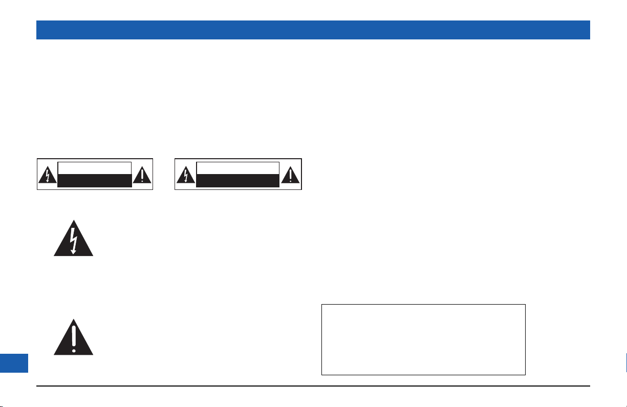
Warnings on your set-top
CAUTION
RISK OF ELECTRIC SHOCK
DO NOT OPEN
The lightning flash with arrowhead symbol,
within a triangle, is intended to alert you to the
presence of uninsulated “dangerous” voltages
within your set-top’s enclosure that may be of
sufficient magnitude to constitute a risk of
electric shock to persons.
The exclamation point within a triangle is
intended to alert you to the presence of
important instructions in the literature
2
accompanying your set-top.
ATTENTION
RISQUE DE CHOC ELECTRIQUE
NE PAS OUVRIR
Other warnings
TO REDUCE THE RISK OF ELECTRIC SHOCK, DO NOT REMOVE THE
COVER OF YOUR SET-TOP.
THERE ARE NO USER-SERVICEABLE PARTS INSIDE IT.
TO REDUCE THE RISK OF FIRE OR ELECTRIC SHOCK, DO NOT
EXPOSE THIS SET-TOP TO RAIN OR MOISTURE.
DO NOT PERFORM ANY SERVICING UNLESS YOU ARE QUALIFIED TO DO
SO BY PACE. REFER ALL SERVICING TO QUALIFIED SERVICE PERSONNEL.
SERVICING THE SET-TOP YOURSELF WILL INVALIDATE THE WARRANTY.
Installation
The installation of your set-top should be carried out by a qualified
installer and should conform to local codes.
Note to the installer
This reminder is provided to call the attention of the cable-TV-system
installer to Section 820-40 of the National Electrical Code (USA),
which provides guidelines for proper grounding and, in particular,
specifies that the cable ground shall be connected to the grounding
system of the building, as close to the point of cable entry as is practical.
Service address:
Pace Micro Technology (Support Services) Ltd.
3701 FAU Boulevard, Suite 200
Boca Raton
Florida, 33431, U.S.A.
Page 4
IMPORTANT SAFETY INSTRUCTIONS
Before you install or use the apparatus, you must read
and understand these Important Safety Instructions.
At all times when using the apparatus you must follow
these Important Safety Instructions to reduce the risk of
fire, electrical shock and injury to persons.
1. Read these instructions.
2. Keep these instructions.
3. Heed all warnings.
4. Follow all instructions.
5. Do not use this apparatus near water.
6. Clean only with dry cloth.
7. Do not block any ventilation openings. Install in accordance
with the manufacturer’s instructions.
8. Do not install near any heat sources such as radiators, heat
registers, stoves, or other apparatus (including amplifiers)
that produce heat.
9. Do not defeat the safety purpose of the polarized or
grounding-type plug. A polarized plug has two blades with
one wider than the other. A grounding type plug has two
blades and a third grounding prong. The wide blade or the
third prong are provided for your safety. If the provided plug
does not fit into your outlet, consult an electrician for
replacement of the obsolete outlet.
10. Protect the power cord from being walked on or pinched
particularly at plugs, convenience receptacles, and the point
where they exit from the apparatus.
11. Only use attachments/accessories specified by the
manufacturer.
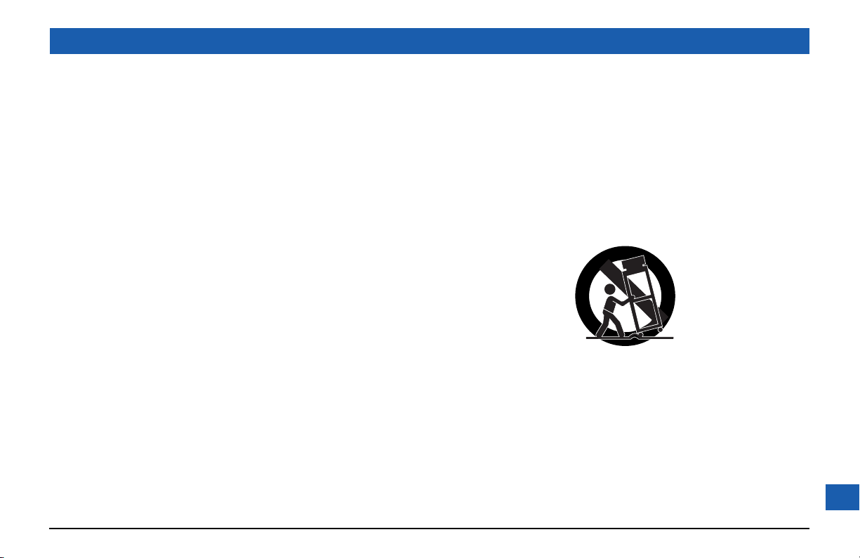
12. Use only with the cart, stand, tripod, bracket, or table
specified by the manufacturer, or sold with the apparatus.
When a cart is used, use caution when moving the cart/
apparatus combination to avoid injury from tip-over.
13. Unplug this apparatus during lightning storms or when
unused for long periods of time.
14. Refer all servicing to qualified service personnel. Servicing is
required when the apparatus has been damaged in any way,
such as power-supply cord or plug is damaged, liquid has
been spilled or objects have fallen into the apparatus, the
apparatus has been exposed to rain or moisture, does not
operate normally, or has been dropped.
3
Page 5

SAFETY INFORMATION (cont.)
In addition to the Important Safety Instructions, please read the
Safety Information below.
Power sources
You must operate your set-top only from the type of power source
indicated on the marking label. If you are not sure of the type of power
supply to your home, consult your dealer or local power company.
Overloading
Do not overload wall outlets, extension cords or other power
outlets as this can result in a risk of fire or electric shock.
Lightning
For added protection for your set-top during a lightning storm, or
when it is left unattended and unused for long periods of time,
disconnect the antenna, cable system and telecommunication line
cord from your set-top. See also item 13 in the Important Safety
Instructions.
Placement and mounting
Do not place your set-top on an unstable or uneven surface. Your
set-top may fall, causing serious injury to a child or adult and serious
damage to your set-top. If you mount your set-top, for example to
a wall or ceiling, follow the manufacturer’s instructions and use a
mounting accessory recommended by the manufacturer. See also
item 12 in the Important Safety Instructions.
4
Ventilation
Slots and openings in the casing of your set-top are provided for
ventilation, to ensure reliable operation of your set-top and to
protect it from overheating.
• never block the ventilation openings by placing your set-top on
a bed, sofa, rug or other similar surface;
• never cover the ventilation openings with items such as
newspapers, table-cloths or curtains;
• do not place your set-top in a built-in installation such as a
bookcase or rack unless proper ventilation is provided or you
have adhered to the manufacturer’s instructions;
• maintain a minimum distance of 3 inches around your set-top
for sufficient ventilation.
See also item 7 in the Important Safety Instructions.
Water and moisture
Do not expose this set-top to dripping or splashing and ensure that
no objects filled with liquids, such as vases, are placed on your set-top.
See also item 5 in the Important Safety Instructions.
Entry of objects and liquids
Never push objects of any kind into your set-top through openings
as they may touch dangerous voltage points or short-out parts that
could result in fire or electric shock. Never spill liquid of any kind on
your set-top.
Page 6
SAFETY INFORMATION (cont.)
Risk of fire or scorching
Never place naked flame sources, such as lighted candles, on your
set-top.
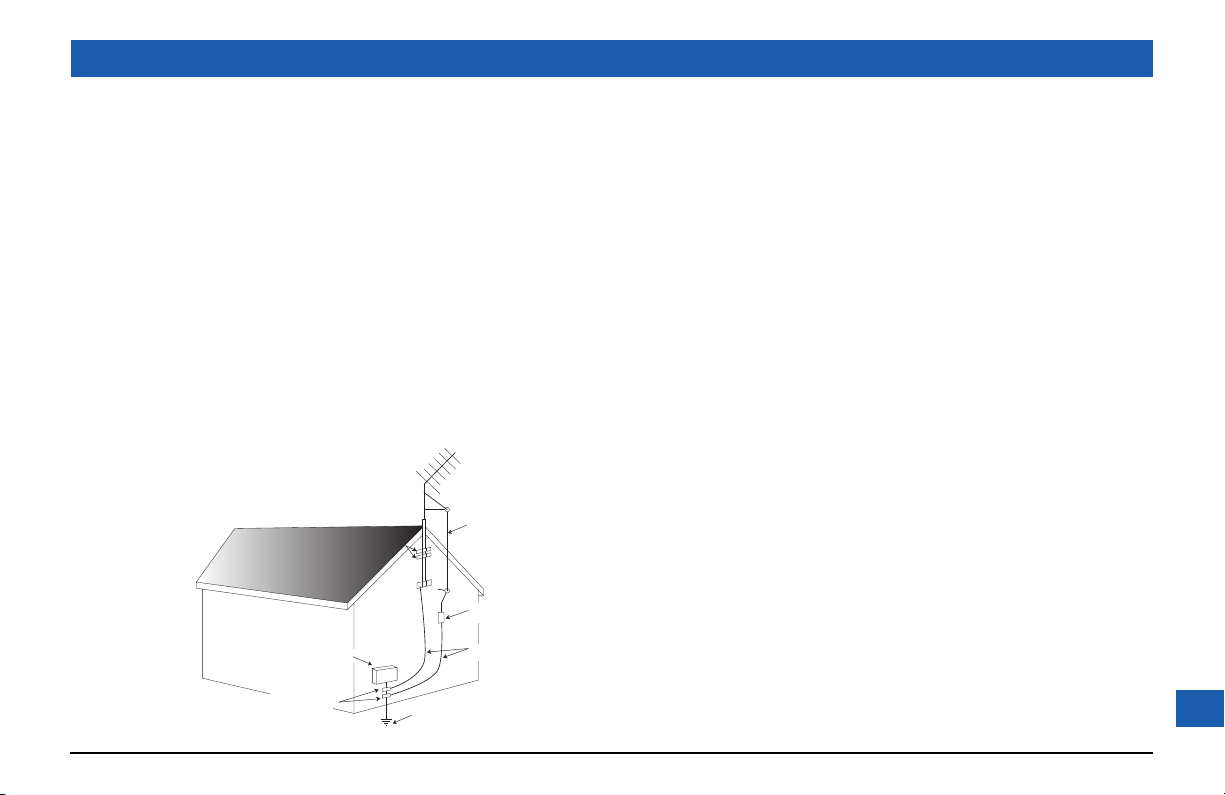
Outdoor antenna grounding
Be sure that any outside antenna or cable system connected to
your set-top is grounded so as to provide some protection against
voltage surges and static charges that have built up. Article 810 of
the National Electrical Code (USA), ANSI/NFPA 70 provides
information with regard to proper grounding of the mast and
supporting structure, grounding of the lead-in wire to an antennadischarge unit, size of grounding conductors, location of antennadischarge unit, connection to grounding electrodes and
requirements for the grounding electrode. See the diagram below.
(Example
antenna
ground clamps
electric service equipment
ground clamps
antenna lead-in wire
antenna-discharge unit
(NEC section 810-20)
grounding conductors
(NEC section 810-21)
power service grounding electrode system
(NEC ART 250, PART H)
Power lines
You must not locate an outside antenna system in the vicinity of
overhead power lines or other electric light or power circuits, or where
it can fall into such power lines or circuits. When installing an outside
antenna system, you must take extreme care to avoid touching such
power lines or circuits, as contact with them might be fatal.
Transporting
Move the combination of set-top and cart with care. Quick stops,
excessive force and uneven surfaces may cause the combination of
set-top and cart to overturn. See also item 12 in the Important
Safety Instructions.
Ambient temperature
The operating temperature range of your set-top is 32-104°F. If the
ambient temperature around your set-top falls outside this range,
you must correct this in order for your set-top to work correctly
and safely. For example, if the temperature is too high, switch on
the air conditioning.
Replacement parts
When replacement parts are required, be sure that the service
technician has used replacement parts specified by the
manufacturer or that have the same characteristics as the original
part. Unauthorized substitutions may result in fire, electric shock or
other hazards. See also item 14 in the Important Safety Instructions.
5
Page 7
SAFETY INFORMATION (cont.)
Safety check
Upon completion of any servicing or repairs to your set-top, ask the
service technician to perform safety checks to determine that your
set-top is in its proper operating condition. See also item 14 in the
Important Safety Instructions.
SAVE THIS INFORMATION FOR FUTURE REFERENCE
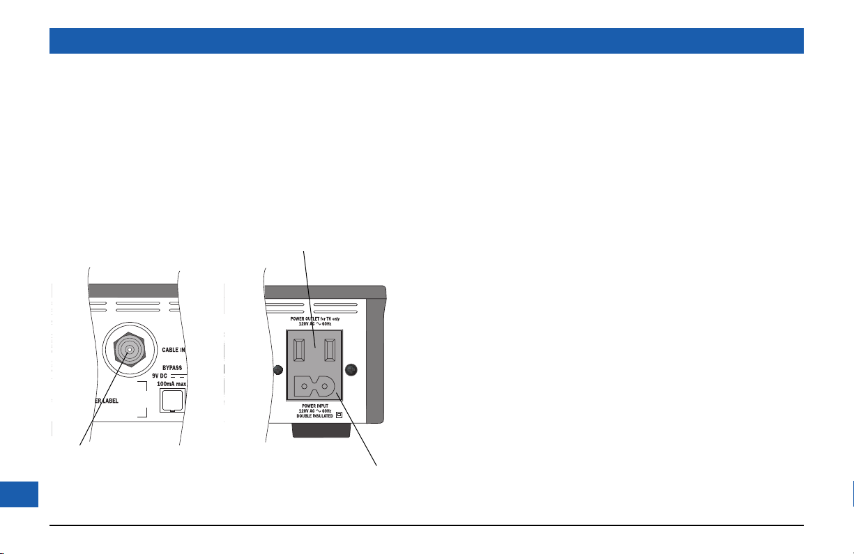
The POWER OUTLET plug is designed only for connection to the AC
power cord for a TV. The maximum power it can supply is 500 watts.
Do not connect any equipment that uses more than 500 watts, or any
non-TV equipment such as a toaster or hair dryer.
The CABLE IN connector is designed for
connection to a cable network only.
You must not connect any other equipment,
6
such as a VCR, to this input.
POWER INPUT
Safety aspects of connections
Full details of the rear panel are on page 8.
Connecting
Do not connect your set-top (or any other equipment such as a TV
or VCR) to the power supply until you have properly connected all
the other cables.
Your set-top operates with a 120 V AC, 60 Hz power supply. Do
not connect your set-top to any supply other than this.
This set-top is equipped with a two-wire power cord, with a
polarized plug at one end. The other end of the cord is fitted with
a polarized connector, which is shaped such that it can only be fitted
one way into the power input jack of your set-top. Connect this
end first, before inserting the polarized plug into the wall socketoutlet.
Disconnecting
Disconnect your set-top from the power supply before you
disconnect any other equipment from its rear panel.
The only way to disconnect your set-top from the power supply is
to remove the power cord from the wall socket-outlet. Your settop must therefore be installed near to the wall socket-outlet,
which should be easily accessible.
Page 8

SAFETY INFORMATION (cont.)
Epilepsy and on-screen images
Certain people are susceptible to epileptic seizures or losing
consciousness when faced with certain types of flashing lights in our
daily environment.
These people are exposed to the risk of seizures if they watch
certain television images or if they view certain images while they
are browsing the Web. These phenomena may appear even when
the subject has no previous history of this problem or has never
suffered an epileptic seizure.
If you, or a member of your family, has already suffered symptoms
linked to epilepsy (seizure or loss of consciousness) in the presence
of stimulation by light, please consult your doctor before using this
product.
If you or any person using the equipment experiences dizziness,
involuntary movements or convulsion, please immediately stop
viewing and consult a doctor.
When you are browsing the Web or playing a Web-based game,
take the following precautions:
• Use the equipment in a well-lit room, and turn down the
brightness of your television screen.
• Sit at a reasonable distance from your television screen.
• Take a break for ten minutes every hour.
You should avoid using the Web if you are tired or have lost some
sleep.
Regulatory information
CAUTION: Do not attempt to modify your set-top without
written authorization from the manufacturer. Unauthorized
modification could void your authority to operate your set-top.
NOTE
Your set-top has been tested and found to comply with the limits for
a Class B digital device, pursuant to Part 15 of the FCC Rules. These
limits are designed to provide reasonable protection against harmful
interference in a residential installation. Your set-top generates, uses
and can radiate radio-frequency energy and, if not installed and used in
accordance with the instructions, may cause harmful interference to
radio communications.
However, there is no guarantee that interference will not occur in a
particular installation. If your set-top does cause harmful interference
to radio or television reception, which can be determined by turning
your set-top off and on, you are encouraged to try to correct the
interference by one or more of the following measures:
• Reorient or relocate the receiving antenna.
• Increase the separation between your set-top and the receiver.
• Connect your set-top to an outlet on a circuit different from that to
which the receiver is connected.
• Consult your dealer or an experienced radio/TV technician for help.
7
Page 9

REAR PANEL
COMPONENT VIDEO OUT
VIDEO OUT
IR RECEIVE
Infra-red input from
a remote “eye”
CABLE IN
From cable
service-provider
BYPASS
For optional RFbypass module
8
Component video output
for analog HDTV
AUDIO IN
Audio baseband input
(stereo, L and R)
AUDIO OUT
Two pairs of audio
baseband outputs
(stereo, L and R)
IR TRANSMIT
Infra-red output to
control a VCR
VIDEO IN
Video baseband input
COMPONENT VIDEO IN
Component analog video input
HIGH-DEFINITION MULTIMEDIA INTERFACE (HDMI)
Video and audio output for
digital HDTV
S-VIDEO OUT
S-video output
Video baseband output
1394 (not fitted on all units)
Two connections to
1394-compatible devices
DIGITAL AUDIO IN
Electrical S/PDIF audio
OPTICAL AUDIO IN
Optical S/PDIF audio input
DIGITAL AUDIO OUT
Electrical S/PDIF audio output
POWER OUTLET
(500 W max.)
POWER INPUT
(Make this
connection
last of all)
OPTICAL AUDIO OUT
Optical S/PDIF audio output
Page 10

REAR PANEL (cont.)
POWER OUTLET Connect the TV’s power cord here to provide AC power to your TV.
POWER INPUT Connect your set-top’s power cord here.
CABLE IN Connect the cable service here. Optional RF-bypass module also connects here.
BYPASS Connect an optional RF-bypass module here, to receive power from set-top.
AUDIO IN Connect to the stereo audio outputs on your DVD player (or similar).
AUDIO OUT TV and
AUDIO OUT VCR
HDMI (high-definition
multimedia interface)
DIGITAL AUDIO OUT Connect to the
DIGITAL AUDIO IN Connect to any digital audio output that loops through your set-top.
VIDEO IN Connect to the video baseband output on your DVD player (or similar).
VIDEO OUT Connect to the video baseband input on, typically, your VCR.
OPTICAL AUDIO OUT Connect to the optical digital audio input on optional digital audio equipment.
OPTICAL AUDIO IN Connect to any digital audio output that loops through your set-top.
S-VIDEO OUT Connect to the S-video baseband input (if present) on, typically, your VCR.
COMPONENT VIDEO OUT If your HDTV does
COMPONENT VIDEO IN Connect equipment such as a DVD player, if it has component video jacks.
IR TRANSMIT Connect to an optional VCR controller (IR transmitter).
IR RECEIVE Connect to an optional “remote eye” (IR receiver).
1394 (not fitted on all units) Connect to up to two 1394-compatible devices. (E.g. external hard disks or 1394 TV).
Connect to the stereo audio inputs on your stereo TV, stereo VCR or optional stereo
amplifier (the output is the same from both pairs of jacks).
If your HDTV has an HDMI, connect it here for
(instead of to AUDIO and COMPONENT VIDEO connectors).
electrical
such as an audio decoder or home theater receiver.
digital audio input on optional digital audio equipment,
not
have an HDMI (see above), connect it here.
digital
audio/video connection
WARNINGS
Do not connect your set-top (or
any other equipment such as a TV
or VCR) to the AC power supply
until you have properly connected
all the other cables.
Disconnect your set-top from the
AC power supply before you
disconnect any other equipment
from its rear panel.
The power outlet is designed only for
connection to the AC power cord for
a TV. The maximum power it can
supply is 500 watts. Do not connect
any equipment that uses more than
500 watts, or any non-TV equipment
such as a toaster or hair dryer.
The cable input is designed for
connection to a cable network only.
You must not connect any other
equipment, such as a VCR, to this
input.
Any cable connected to DIGITAL
AUDIO jacks must be 75 ohm
coaxial, not regular audio cable.
9
Page 11

CONNECTING TO THE AC POWER SUPPLY
WARNINGS
Do not connect your set-top (or any other equipment such as a TV or VCR) to the AC power supply until
you have properly connected all the other cables.
Do not defeat the safety purpose of the polarized plugs on power cords. A polarized plug has two blades
with one wider than the other. This plug fits into the outlet in only one way; match the wide blade of the
plug to the wide slot of the outlet.
Disconnect your set-top from the AC power supply before you disconnect any other equipment from its
rear panel.
The only way to disconnect your set-top from the AC power supply is to remove the AC power cord (or
switch the wall socket-outlet switch, if present, to its OFF position). Your set-top must therefore be
installed near to the AC power socket-outlet, which should be easily accessible.
Connecting your TV to the AC power supply
If your TV has a rating of less than 500 W, connect the power cord from your TV into the connector
labeled “POWER OUTLET” on the rear panel of your set-top. This saves a wall outlet (although, if
your TV is rated 500 W or more, you must connect it to a wall outlet).
Connecting the power cord to your set-top
Before you connect your set-top to a wall outlet, connect the polarized socket on the power cord
into the plug labeled “POWER INPUT” on your set-top’s rear panel.
Connecting equipment to the AC wall outlets
Connect the polarized plugs on the power cords from your set-top, VCR and any other equipment
10
into AC wall outlets. If these outlets have switches, switch them to ON.
NOTE
On pages 11 and 12 there are two
typical connection set-ups for an
HDTV, VCR, DVD player and home
theater receiver.
These set-ups make efficient use of
the connectors on your set-top.
However, depending on your other
equipment and the connectors on
it, the person who installed your
system may have chosen to connect
things up differently.
Page 12

CONNECTION TO THE AC POWER SUPPLY (cont.)
WALL AC OUTLETS
VCR
DVD
HOME THEATER
RECEIVER
CABLE INPUT
POWER
POWER
POWER
TV / RF
OUT
ANTENNA/
RF IN
LEFT
AUDIO OUT
RIGHT
AUDIO OUT
S-VIDEO
OUT
S-VIDEO
IN
VCR IN
VIDEO IN
LEFT
AUDIO IN
RIGHT
AUDIO IN
VIDEO IN
LEFT
AUDIO IN
RIGHT
AUDIO IN
DIGITAL AUDIO OUT
OPTICALCOAXIAL
DIGITAL AUDIO IN
COAXIAL
AUDIO IN
VIDEO OUT
LEFT
AUDIO OUT
RIGHT
AUDIO OUT
COMPONENT
VIDEO OUT
OPTICAL
AUDIO IN
HDTV
COMPONENT
VIDEO IN
Y IN
S-VIDEO
PB/CB IN
IN
Y
PB/CB
PR/CR
ANTENNA/
RF IN
PR/CR IN
LEFT
AUDIO IN
RIGHT
AUDIO IN
VIDEO IN
LEFT
AUDIO IN
RIGHT
AUDIO IN
HDMI
POWER
WALL AC OUTLET
11
Page 13

CONNECTION TO THE AC POWER SUPPLY (cont.)
12
WALL AC OUTLETS
VCR
DVD
HOME THEATER
RECEIVER
CABLE INPUT
POWER
POWER
POWER
TV / RF
OUT
ANTENNA/
RF IN
LEFT
AUDIO OUT
RIGHT
AUDIO OUT
S-VIDEO
OUT
S-VIDEO
VCR IN
VIDEO IN
LEFT
AUDIO IN
RIGHT
AUDIO IN
IN
VIDEO IN
LEFT
AUDIO IN
RIGHT
AUDIO IN
DIGITAL AUDIO OUT
OPTICALCOAXIAL
DIGITAL AUDIO IN
COAXIAL
AUDIO IN
OPTICAL
AUDIO IN
VIDEO OUT
LEFT
AUDIO OUT
RIGHT
AUDIO OUT
COMPONENT
VIDEO OUT
Y
PB/CB
PR/CR
HDTV
ANTENNA/
RF IN
COMPONENT
VIDEO IN
Y IN
PB/CB IN
PR/CR IN
LEFT
AUDIO IN
RIGHT
AUDIO IN
S-VIDEO
IN
VIDEO IN
LEFT
AUDIO IN
RIGHT
AUDIO IN
POWER
WALL AC OUTLET
Page 14

OPERATING YOUR SET-TOP
power
To turn on your
set-top, press
the power
button.
The light around
the button changes
from red to green.
Turning your set-top on and off
After you have connected your set-top to the AC wall outlet (and switched this outlet ON, if it has
a switch), the light around the
power
button on your set-top’s front panel should be red.
Wait for a few seconds, then press the button labeled
turn it on. The light around the
on.
If the light around the
To turn your set-top on or off at any time, press the
button on your remote control.
It is important that, unless there is a lightning storm or you will be away from your home for a long time,
you do not unplug your set-top at the wall AC outlet (or do not switch it off there, if the outlet has a
switch). Your set-top can not be updated with new features, through the cable, if it is disconnected from
the AC power supply.
You can use the General Settings screen to set the POWER OUTLET (AC Outlet) on your set-top to be
“Always on” or “On with cable box (Settop)”. With this second setting, a TV attached to POWER OUTLET
will turn off when you turn off your set-top and will turn on when you turn on your set-top.
power
power
on the front panel of your set-top to
power
button goes from red to green, to show that your set-top is
button is neither red nor green, there is a problem.
power
button on its front panel or the
NOTES
CBL
13
Page 15

OPERATING YOUR SET-TOP (cont.)
Using your remote control
It is your cable TV service provider that determines the digital channels, services and screen
information that you see on your TV when you use your set-top and its remote control.
Consult the information supplied by your cable operator for details on how to make the most of the
digital cable services. Also read the operating instructions that are supplied with your remote control.
Activating baseband loopthrough for a DVD or similar equipment
To activate baseband loopthrough, simply turn off your set-top by pressing the
remote control (or the
the
power
button is red.
If you activate baseband loopthrough, the following occur:.
COMPONENT VIDEO IN loops through to COMPONENT VIDEO OUT
VIDEO IN loops through to VIDEO OUT
AUDIO IN loops through to AUDIO OUT TV and AUDIO OUT VCR
DIGITAL AUDIO IN loops through to DIGITAL AUDIO OUT
OPTICAL AUDIO IN loops through to OPTICAL AUDIO OUT
power
button on the front panel). When your set-top is off, the light around
CBL
button on your
14
Page 16

OPERATING YOUR SET-TOP (cont.)
p
Using the front-panel buttons
You can use the buttons on the front panel to operate your set-top, if, for example, there is a problem with your remote control.
.
ower button
To turn your set-top
on/off
USB connector
Window that receives signal from
remote control (do not block it)
BYPASS: Lights while the
RF-bypass feature is on
Smart-card slot
MAIL: Lights when there
is an unread message.
HDTV: Lights for a high-definition source
signal and during display setting (see page 16)
settings button
To display on-screen
menus
select button (+)
To select items in
menus/guides
ch+
power
power light
(around button)
Lights green when your
set-top is on and red
when it is off
Shows the program channel
number or the time
(or sometimes other information)
BYPASS
HDTV
display
guide
To display an on-screen guide
To display on-screen program information
To remove on-screen information
info
exit
vol-
settings
ch-
To change channel or move up/
down in an on-screen menu/guide
To adjust volume or move left/
right in an on-screen menu/guide
vol+
15
Page 17

OPERATING YOUR SET-TOP (cont.)
Using an RF-bypass module
If an RF-bypass module has been installed on the rear panel of your set-top, the regular (analog)
channels can bypass your set-top. For you to turn RF-bypass on or off, your set-top must be turned
on. However, once set, the RF-bypass will work even when your set-top is turned off.
To turn on the RF-bypass feature, press the
To turn off the RF-bypass feature, press the
While the RF-bypass is on, the word BYPASS is lighted on the front panel of your set-top.
When the RF-bypass is on
(analog) channels and watch that channel on your TV. This may be a different channel from the
channel that your set-top is tuned to. (The number of the channel it is tuned to is shown on its front
panel.) You can record on your VCR the channel that your set-top is tuned to. This means that, when
the RF-bypass is on, you can watch a regular (analog) channel on your TV and, at the same time,
record a
When the RF-bypass is off
the same channel that your VCR receives. So, when the RF-bypass is off, you can record only the
channel that you are watching on your TV.
different
, you can use the TV’s remote control to tune to any of the available regular
channel (digital or analog) on your VCR.
, you will see on your TV the channel that your set-top is tuned to. This is
BYPASS
BYPASS
button on your remote control.
button again.
Lightning storms
Occasionally, a lightning storm may affect your set-top. It may appear that it has stopped working, but
you can easily restore its operation as follows.
Unplug your set-top’s power cord at the wall AC outlet. Then plug this power cord in again at the
16
wall AC outlet (and, if there is a switch by this outlet, switch it to its ON position).
Page 18

SOLVING PROBLEMS
If the installed system does not seem to be working properly,
then carry out the following checks, in the order shown.
Check Suggested solution Further checks, if there is still a problem
Is anything lighted on
your set-top’s front
panel?
YES
Does the remote
control operate your
set-top?
YES
Please see the next page
NO
NO
Power may not be reaching your set-top.
Make sure that the power cord is
properly plugged in. If there is a switch by
the wall AC power outlet, switch it to
ON.
Your set-top may not be turned on.
Check if the light around the power
button on the front panel is green. If it is
red, press the
front panel to turn on your set-top.
power
first make sure that all the cables are securely connected
Check that the wall AC power outlet is working
(for example by plugging in a lamp).
Check that nothing is blocking the path from your
remote control to the front panel (or remote eye,
if you are using one).
button on the
Check that your remote control is currently set to
operate your set-top (consult the instructions
supplied with your remote control).
If your remote control will still not operate your
set-top, replace the batteries in your remote
control.
If there is still a problem, try to operate your settop by using its front-panel buttons. If this works,
then your remote control may be faulty.
,
17
Page 19

SOLVING PROBLEMS (cont.)
Check Suggested solution Further checks, if there is still a problem
18
Can you see a picture
on your TV screen?
YES
Is the picture distorted
or too small?
NO
Please see the next page
NO
YES
Your TV and other equipment may not be
turned on. Check that they are plugged
into AC power outlets and turned on.
Note:
In the General Settings screen,
“AC Outlet” may be set to “On with
cable box (Settop)”. If you have
connected your TV to the POWER
OUTLET (AC outlet) on your set-top,
the setting “On with cable box (Settop)”
means that, when you turn off your settop, your TV will turn off, and, when you
turn on your set-top, your TV will turn
on. You may wish to keep this feature, or
you may wish to set “AC Outlet” to
“Always on”.
Check that the screen resolution and
aspect ratio, as set on your set-top, are
appropriate for your TV. Change them if
necessary.
Make sure the RF-bypass feature is turned OFF (the
word
BYPASS
Check that you have selected the appropriate AV
input on your TV: HDMI, COMPONENT VIDEO
(YPbPr) or VIDEO IN (depending on how your
system is connected up).
If the video path between your set-top and your TV
loops through other equipment (such as a VCR)
you may need to turn off this equipment for the
loopthrough to work.
Check the HDTV Resolution setting . Note that
the component video (YPbPr) jacks on some
HDTVs do not accept a
If the screen resolution and aspect ratio seem to be
correct, try to improve the picture by using the #
button on your set-top’s remote control or any
zoom controls on your TV itself (consult the
instructions that came with your TV).
on the front panel is not lighted).
480i
input.
Page 20

SOLVING PROBLEMS (cont.)
Check Suggested solution Further checks, if there is still a problem
Can you display menus
and guides on the screen?
YES
Is there any sound?
YES
Can you see and hear a
DVD that you are
trying to play?
YES
Can you see only
regular (analog)
channels but not any
digital channels?
NO
NO
NO
YES
If your TV is connected to the VIDEO
OUT or S-VIDEO OUT jacks, then you
will see menus on analog (regular) channels
only if the screen resolution is set to
and nothing is connected at the HDMI.
Check that the audio cables are securely
and correctly connected.
If you can hear only mono sound, first
check that the program is likely to have
stereo sound (an old movie, for example,
may not be in stereo).
For the signal to loop through your settop from a DVD (or similar equipment)
to reach your TV, you must activate
baseband loopthrough by turning off
your set-top.
The RF-bypass feature may be turned on.
Press the
remote control to turn the feature OFF
(make sure the word
lighted on the front panel).
BYPASS
button on your
BYPASS
480i
is not
Check the resolution setting and change it if
necessary.
Check that you have not muted the sound on your
set-top and/or TV. Adjust the volume control on
your set-top and/or TV.
If you have a DVI TV that is connected to the settop’s HDMI connector, make sure there are also
audio cables between your set-top and TV.
Check that all the audio and video cables are
securely and correctly connected, including any to a
home theater receiver that you may be using to
enhance the sound.
19
Page 21

www.pacemicro.com
Pace and are trademarks and/or registered trademarks of Pace Micro Technology plc.
502-1403603
 Loading...