


PETROL INVERTER GENERATOR
2500W
ASSEMBLY & SAFETY WARNINGS
0218 |
-2500 |

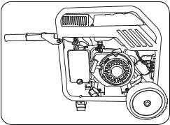
KNOW YOUR PRODUCT
INVERTER GENERATOR
1. |
Frame |
11. |
Fuel Tap |
2. |
Choke |
12 |
Display Meter |
3. |
Recoil Starter |
13. |
DC Overload Reset |
4. |
Fuel Gauge |
14. |
Engine On/Off Switch |
5. |
Fuel Tank Cap |
15. |
RCBO / AC Power Switch |
6. |
Control Panel |
16. |
12Volt DC Outlet |
7. |
Oil Dipstick |
17. |
Status LEDs |
8. |
Oil Fill Port |
18. AC Socket x 2 |
|
9. |
Transport Handle |
19. Grounding Terminal |
|
10. Air Filter
1 2 3 4 5
6
7 8
12 13
14
9 |
|
10 |
|
11 |
|
|
|
|
|
|
|
|
|
|
|
|
|
15 |
|
16 |
|
17 |
|
18 |
|
19 |
|||
|
|
|
|
|
|
|
|
|
|
|
|
|
|
|
Page 2

TOOLS&ACCESSORIES
19. |
Oil Filler Bottle |
22. Spare Spark Plug |
20. |
Battery Charging Cable |
23. Generator Oil |
21. |
Spark Plug Wrench |
|
19
20
 23
23
22
21
CONTENTS
Know Your Product.......................................................... |
Page 2-3 |
Assembly Procedure....................................................... |
Page 4-6 |
Safety Warnings for Generators...................................... |
Page 7-12 |
Page 3

ASSEMBLY
WARNING! DURING ASSEMBLY ENSURE THE GENERATOR IS SWITCHED OFF.
1.Carefully remove contents from the packaging.
2.Select a firm, level surface on which to assemble the generator.
Fitting the Wheels
1.Assemble one wheel onto the large diameter end of the wheel shaft, ensuring the side of the wheel with the raised centre faces the middle of the shaft.
Place the washer into the wheel hub and then screw the bolt tightly into the wheel shaft. You can then place the wheel cap over the bolt head.
2.Insert the other end of the wheel shaft through the mounting holes in the frame and tighten the nut onto the shaft using 15mm and 17mm spanner.
Note: Do not over tighten this nut causing the wheel to not rotate.
3.Repeat this process for the second wheel.
Page 4

Fitting the Support Feet
1.Place the support foot under the frame aligning with the holes in the side frame. Insert the support foot bolts through the holes and fasten tightly with the nut.
2.Repeat this step with the second support foot on the other side.
Fitting the Transport Handles
1.Align the hole of the transport handle bracket with the hole in the frame as you push the bracket over the frame.
2.Insert the handle bolt from the outside through the bracket and frame ensuring that the plastic washers are inserted between the bracket and frame. Fasten each bolt to the frame in position with the nut provided.
3.Repeat the above steps for the second handle.
Page 5
4.The transport handle will pivot allowing it to hang out of the way when not in use.
These handles can be used to transport the generator easily.
Page 6
 Loading...