


|
|
WHAT’S IN THE BOX |
|
DRILL |
Head Assembly |
|
|
PRESS |
Table |
Eye Shield |
|
350W |
5 Speed |
|
|
INSTRUCTION MANUAL |
|
|
|
SPECIFICATIONS |
Base |
Steel Column |
|
|
|
||
Motor Size: |
350W |
|
|
Input: |
230 – 240V ~ 50Hz |
|
|
No Load Speed: |
580, 850, 1220, |
|
|
|
1650, 2650/min |
|
13mm Keyed |
Chuck: |
13mm Keyed |
Feed Wheel |
|
Spindle Travel: |
50mm |
Handles x 3 |
Chuck |
Spindle Shaft to |
|
|
|
Column Distance: |
104mm |
|
|
Column Height: |
395mm |
|
|
Table Size: |
160x160mm |
Column Support |
Pulley Cover |
Weight: |
16.4kg |
||
ozito.com.au |
Bolts x 3 |
Knob Assembly |
|
|
|
||
|
|
|
Chuck Key |
|
|
Belt (assembled |
|
|
|
to pulleys) |
4 & 3mm Hex Keys |
|
|
|
|
DP-350
WARRANTY
IN ORDER TO MAKE A CLAIM UNDER THIS WARRANTY YOU MUST RETURN THE PRODUCT TO YOUR NEAREST BUNNINGS WAREHOUSE WITH YOUR BUNNINGS REGISTER RECEIPT. PRIOR TO RETURNING YOUR PRODUCT FOR WARRANTY PLEASE TELEPHONE OUR CUSTOMER SERVICE HELPLINE:
Australia 1800 069 486 New Zealand 0508 069 486
The benefits provided under this warranty are in addition
to other rights and remedies which are available to you at law.
Our goods come with guarantees that cannot be excluded at law. You are entitled to a replacement or refund for a major
failure and for compensation for any other reasonably foreseeable loss or damage. You are also entitled to have the goods repaired or replaced if the goods fail to be of acceptable quality and the failure does not amount to a major failure.
Generally you will be responsible for all costs associated with a claim under this warranty, however, where you have suffered any additional direct loss as a result of a defective product you
may be able to claim such expenses by contacting our customer service helpline above.
TO ENSURE A SPEEDY RESPONSE PLEASE HAVE THE MODEL NUMBER AND DATE OF PURCHASE AVAILABLE. A CUSTOMER SERVICE REPRESENTATIVE WILL TAKE YOUR CALL AND ANSWER ANY QUESTIONS YOU MAY HAVE RELATING TO THE WARRANTY POLICY OR PROCEDURE.
3 YEAR REPLACEMENT WARRANTY
Your product is guaranteed for a period of 36 months from the original date of purchase and is intended for DIY (Do It Yourself) use only. If a product is defective it will be replaced in accordance with the terms of this warranty. Warranty excludes consumable parts, for example: feed wheel handles, keyed chuck, hex key, chuck key, belt.
WARNING
The following actions will result in the warranty being void.
•If the tool has been operated on a supply voltage other than that specified on the tool.
•If the tool shows signs of damage or defects caused by or resulting from abuse, accidents or alterations.
•Failure to perform maintenance as set out within the instruction manual.
•If the tool is disassembled or tampered with in any way.
•Professional, industrial or high frequency use.
OZITO Australia/New Zealand (Head Office) 1-23 Letcon Drive, Bangholme, Victoria, Australia 3175.
0714

|
|
|
3 KNOW YOUR PRODUCT |
|
SETUP & PREPARATION |
|
|
|
DRILL PRESS
1. Pulley cover |
|
12. |
Column support |
|
2. Pulley cover knob |
|
13. |
Base |
|
3. Feed wheel handles |
|
14. |
Head assembly |
|
4. Belt tension knob |
|
15. |
Depth indicator |
|
5. Head lock screws |
|
16. |
ON/OFF Switch |
|
6. Feed wheel hub |
|
17. |
Depth indicator lock nuts |
|
7. Column |
|
18. |
Depth rod support |
|
8. Table |
|
19. |
Depth rod |
|
9. Table support |
|
20. |
13mm Keyed chuck |
|
10. Table support lock |
|
21. |
Depth scale |
|
11. Column support bolts x 3 |
|
|
|
1 |
|
|
|
|
|
|
|
|
|
2 |
|
|
|
|
3 |
|
|
|
|
4 |
|
|
|
|
5 |
|
|
|
|
6 |
|
|
|
|
7 |
|
|
|
|
8 |
|
|
|
|
9 |
|
|
|
|
10 |
|
|
|
|
11 |
|
|
|
|
12 |
|
|
|
|
13 |
|
14 |
15 |
10 |
|
|
|
|
|
|
|
16 |
17 |
20 |
|
|
30 |
|
||
|
40 |
|
||
|
50 |
|
||
|
18 |
19 |
|
|
|
20 |
21 |
|
|
ACCESSORIES |
22 |
|
23 |
24 |
22. Chuck key |
|
|
|
|
23. 3mm Hex key |
|
|
|
|
24. 4mm Hex key |
|
|
|
|
ONLINE MANUAL
Scan this QR Code with your mobile device to take you to the online manual.
1. ASSEMBLY
WARNING! DURING ASSEMBLY ENSURE THE  DRILL PRESS IS DISCONNECTED FROM THE POWER SUPPLY.
Assembling the drill press
1.Carefully remove contents from the packaging.
2.Select a firm, level surface on which to assemble the drill press.
3.Select the base and
align the column over the large hole. Align the holes in the column support with those in the base and secure in place using the 3
column support bolts,
spring and flat washers (supplied).
Using a 12mm spanner or shifter
(not supplied) securely tighten all
3 column support bolts.
4.Slide the table support over the column. Using the table support lock, secure the table into the
desired position.
5. Lift the head assembly and slide it down onto the column as far as it will go. To secure in position install the two head lock screw. Tighten using the 4mm Hex key, rotating in a clockwise direction.
6. To fit the feed wheel handles, screw them into the feed wheel hub.
7.To fit the 13mm keyed chuck, first place a piece of timber on
the table and position the 13mm keyed chuck with the jaws retracted under the drive shaft. Raise the table toward the drive
shaft until the 13mm keyed chuck
is approximately 25mm from the drive shaft.
Approx. 25mm
8. To secure the 13mm keyed chuck to the drive shaft gently lower the drive shaft using the feed wheel handles until the drive shaft is pushed into the rear of the 13mm keyed chuck. A gentle tap on the timber is required to secure the 13mm keyed chuck onto the tapered drive shaft.
9. Fit the pulley cover knob to the pulley cover by using the pulley cover knob assembly (supplied).
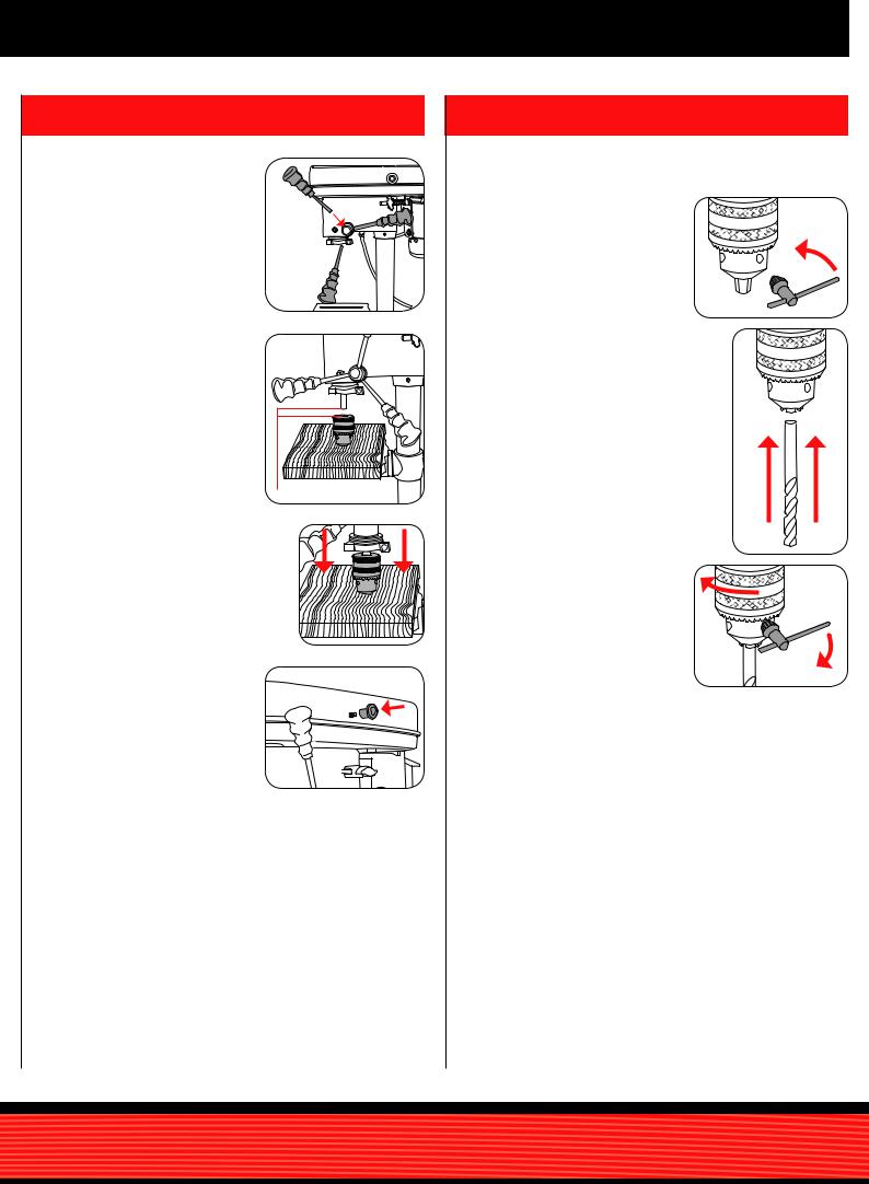
Installing and removing drill bits
1. Using the chuck key, loosen the jaws of the chuck by rotating in an anti-clockwise direction.
2. Insert the drill bit fully into the 13mm keyed chuck.
3. Whilst holding the drill bit in one hand, rotate the top collar of the
13mm keyed chuck in a clockwise direction.
Ensure that you tighten all 3 holes in the 13mm keyed chuck using the chuck key to securely tighten the jaws and hold the drill bit in position.
 Loading...