

Page 1

10 Series CNC
Programming Manual
Code: 45004457K
Rev. 10
PUBLICATION ISSUED BY:
OSAI S.p.A.
Via Torino, 14 - 10010 Barone Canavese (TO) – Italy
e-mail: sales@osai.it
Web: www.osai.it
Copyright 2001-2002 by OSAI
All rights reserved
Edition: July 2001
IMPORTANT USER INFORMATION
This document has been prepared in order to be used by OSAI. It describes the latest release of the
product.
OSAI reserves the right to modify and improve the product described by this document at any time
and without prior notice.
Actual application of this product is up to the user. In no event will OSAI be responsible or liable for
indirect or consequential damages that may result from installation or use of the equipment described
in this text.
Page 2

abc
Page 3

SUMMARY OF CHANGES
General
This publication is issued with reference to Software Release 6.1 (E69).
PAGE UPDATING TYPE
INDEX Updated
CAP. 2
page 4 Note on the use of Circular Interpolation added
page 6 Examples of Circular Interpolation added
page 48-49 Use of the bits in the MOV instruction extended
page 53 Error bits in the Debug ODH variable extended
CAP. 3
page 5 Notes on the use of the “h” address added
UPDATE
10 Series CNC Programming Manual
10 Series CNC Programming Manual (10)
Page 4

abc
Page 5

Preface
10 Series CNC Programming Manual
PREFACE
This manual describes the procedures used for writing part programs with the 10 Series CNC system.
It provides programmers with all the information they need for creating machine control programs.
REFERENCES
For further information:
• 10 Series CNC - AMP Software Characterization Manual
• 10 Series CNC - User Guide
The chapters in this manual are organised in sections. They describe the language elements
(commands and functions) used for managing a specific task, e.g. axis programming, tool
programming, probe management. Programming examples have been introduced in the command
description.
SUMMARY
1. Programming with 10 Series System
This chapter contains the general programming rules of the International Standards Organization
(ISO) standard. The chapter also provides an overview of the programming environment and a
summary of the most used codes.
2. Programming the Axes
This chapter describes axis programming. The G codes and extended commands involved in this
activity are provided with their characteristics. Several examples complete the command
description and give suggestions for programming the major types of movements.
3. Programming Tools and tool offsets
This chapter describes tool programming and provides the functions and instructions used in tool
operation.
10 Series CNC Programming Manual (08) 1
Page 6

Preface
10 Series CNC Programming Manual
4. Cutter Diameter Compensation
This chapter describes cutter compensation. T functions and G codes used in tool compensation
are provided with characteristics and several examples.
5. Programming the Spindle
This chapter describes spindle programming. The G codes and extended commands involved in
this activity are provided with their characteristics. Several examples complete the command
description and give hints for solving the main cases of spindle programming.
6. Miscellaneous Functions
This chapter describes miscellaneous functions and provides a list of M functions with their
meaning and characteristics.
7. Parametric Programming
This chapter deals with special programming applications that use local and system variables.
8. Canned Cycles
This chapter provides a description of the canned cycles available with the control. The G codes
and extended commands used in this activity are provided with their characteristics. Several
examples complete the command description.
9. Paramacros
This chapter describes how paramacros can be used in programs.
10. Probing Cycles
This chapter provides a description of the probing cycles available with the control. The G codes
and extended commands involved in probe management are provided complete with examples.
11. Managing the Screen
This chapter discusses the commands used to handle the system screen from a part programs.
Examples are given to complete the command description.
12. Modifying the Program Execution Sequence
This chapter contains the commands used for modifying the sequence of execution of a part
program. It describes commands for branching, repeating blocks and executing subprograms, as
well as commands for putting the part program on hold and releasing it.
13. High Speed Machining
This chapter describes the high-speed milling features on machine tools with 3 axes.
14. Multiprocess management commands
This chapter shows 10 Series CNC's multi process potentials.
2 10 Series CNC Programming Manual (08)
Page 7

10 Series CNC Programming Manual
15. High level geometric programming (GTL)
This chapter discusses the set of programming instructions available with the GTL utility.
16. Working Cycles for Turning Systems
This chapter provides the instructions for programming macro-cycles of rough-shaping, threading
and groove cutting.
A. Characters and Commands
Appendix A provides a summary of all the characters allowed in the system and gives lists of G
codes, mathematical functions and extended commands.
B. Error Messages
Appendix B provides a list of all the error messages that can occur during programming..
C. Error management
Preface
10 Series CNC Programming Manual (08) 3
Page 8

Preface
10 Series CNC Programming Manual
COMMANDS
Commands are dealt with in the chapters that describe the specific task. A common structure has
been adopted in the command description. For each command, the following information is provided:
• Command name
• Command function
• Command syntax
• Parameters
• Characteristics and notes
• Examples
Where possible, examples consist of a portion of program and a diagram that shows how the
commands in that portion work.
Syntax conventions
Use these conventions with the commands:
SYMBOL MEANING
[ ] Brackets enclose optional entries. Do not enter the brackets.
{ } Braces enclose entries which may be repeated more than once. This could
also be described as a series of alternative entries, i.e. only one of these may be
entered. Alternative entries are separated by a (|). Do not enter the braces in
the command itself.
| A vertical bar separates alternative entries. Do not enter the bar.
Key-words are written in bold. They must be entered exactly as they are represented in the syntax
description.
Parameters that must be passed with commands are indicated by a mnemonic written in italics.
Appropriate values must be entered in place of the mnemonic. Leading zeros can be omitted. For
example, you can program G00 as G, G01 as G1.
Example:
(SCF,[value])
SCF, the comma and parenthesis are key-words and must be written as described. value is a
parameter name and must be replaced by an appropriate value. The brackets indicate that value is an
optional value.
4 10 Series CNC Programming Manual (08)
Page 9

Preface
10 Series CNC Programming Manual
Warnings
For correct control operation, it is important to follow the information given in this manual. Take
particular care with topics bearing one of the mentions: WARNING, CAUTION or IMPORTANT, which
indicate the following types of information:
Draws attention to facts or circumstances that may cause damage to the
control, to the machine or to operators.
WARNING
Indicates information to be followed in order to avoid damage to equipment in
CAUTION
general.
IMPORTANT
Indicates information that must be followed carefully in order to ensure full
success of the application.
Terminology
Some terms appearing throughout the manual are explained below.
Control Refers to the 10 Series numerical control unit comprising front panel unit and
basic unit.
Front Panel Is the interface module between machine and operator; it has a monitor on which
messages are output and a keyboard to input the data. It is connected to the
basic unit.
Basic Unit Is the hardware-software unit handling all the machine functions. It is connected to
the front panel and to the machine tool.
10 Series CNC Programming Manual (08) 5
Page 10

Preface
10 Series CNC Programming Manual
END OF PREFACE
6 10 Series CNC Programming Manual (08)
Page 11

10 Series CNC Programming Manual
INDEX
PROGRAMMING WITH 10 SERIES SYSTEMS
THE PROGRAM FILES.............................................................................................1-1
Program Components......................................................................................1-2
Blocks............................................................................................................1-2
Block Types ....................................................................................................1-4
Programmable Functions .................................................................................1-6
G Codes.........................................................................................................1-9
SYNCHRONISATION AND PROGRAM EXECUTION ...................................................1-13
Default Synchronisation ...................................................................................1-13
Overriding Default Synchronisation....................................................................1-14
Part Program Interpreter ...................................................................................1-14
Sequence of execution.....................................................................................1-15
Programming restrictions for long real (double) formats .......................................1-15
Index
PROGRAMMING THE AXES
AXIS MOTION CODES .............................................................................................2-1
Defining Axis Motion ........................................................................................2-1
G00 - Rapid Axes Positioning ...........................................................................2-2
G01 - Linear Interpolation .................................................................................2-3
G02 G03 - Circular Interpolation........................................................................2-4
CET (PRC) - Circular Endpoint Tolerance...........................................................2-7
FCT - Full Circle Threshold...............................................................................2-8
ARM - Defining Arc Normalisation Mode............................................................2-9
CRT - Circular interpolation speed reduction threshold.........................................2-13
CRK - Circular interpolation speed reduction constant.........................................2-13
Helical Interpolation .........................................................................................2-15
G33 - Constant or Variable Pitch Threading........................................................2-17
Rotary Axes ....................................................................................................2-21
Axes with Rollover...........................................................................................2-23
Pseudo Axes ..................................................................................................2-26
Diameter Axes ................................................................................................2-26
UDA - Dual Axes.............................................................................................2-29
SDA - Special Dual Axes .................................................................................2-31
ORIGINS AND COORDINATE CONTROL CODES ......................................................2-33
G17 G18 G19 - Selecting the Interpolation Plane ................................................2-34
10 Series CNC Programming Manual (10) i
Page 12

Index
10 Series CNC Programming Manual
G16 - Defining the Interpolation Plane ................................................................2-35
G27 G28 G29 - Defining the Dynamic Mode .......................................................2-36
AUTOMATIC DECELERATION ON BEVELS IN G27 MODE .........................................2-41
DLA - Deceleration Look Ahead........................................................................2-42
DYM - Dynamic Mode......................................................................................2-43
MDA - Maximum Deceleration Angle .................................................................2-44
VEF - Velocity Factor......................................................................................2-45
Jerk Limitation.................................................................................................2-47
MOV - Enable Jerk Limitation...........................................................................2-48
Meaning of bits 0 – 3: ..................................................................................2-48
Meaning of bits 6 - 7: ..................................................................................2-49
JRK - Jerk Time Constant .................................................................................2-50
JRS - Jerk Smooth Constant ............................................................................2-51
ODH - Online Debug Help.................................................................................2-53
IPB (DTL) - In Position Band .............................................................................2-55
G70 G71 - Measuring Units..............................................................................2-56
G90 G91 G79 - Absolute, Incremental and Zero Programming .............................2-57
G92 G99 - Axis Presetting ...............................................................................2-59
G04 G09 - Dynamic Mode Attributes.................................................................2-60
t - Block Execution Time ..................................................................................2-61
DWT (TMR) - Dwell Time ..................................................................................2-61
G93 - V/D Feedrate.........................................................................................2-62
VFF - Velocity Feed Forward ............................................................................2-63
CODES THAT MODIFY THE AXES REFERENCE SYSTEM ..........................................2-64
SCF - Scale Factors........................................................................................2-65
MIR - Using Mirror Machining............................................................................2-66
ROT (URT) - Interpolation Plane Rotation...........................................................2-69
UAO - Using Absolute Origins ..........................................................................2-72
UTO (UOT) - Using Temporary Origins...............................................................2-73
UIO - Using Incremental Origins........................................................................2-75
RQO - Requalifying Origins ...............................................................................2-77
OVERTRAVELS AND PROTECTED AREAS...............................................................2-78
SOL (DLO) - Software Overtravel Limits .............................................................2-79
DPA (DSA) - Define Protected Areas .................................................................2-80
PAE (ASC) - Protected Area Enable .................................................................2-82
PAD (DSC) - Protected Area Disable.................................................................2-82
VIRTUAL AXES MANAGEMENT ...............................................................................2-83
Virtual Axes....................................................................................................2-83
Virtual modes available on 10 Series CNC .........................................................2-83
UPR - Rotation of Cartesian axes ......................................................................2-84
Using UPR......................................................................................................2-87
UVP - Programming polar coordinates...............................................................2-91
The minimum radius should be calculated using the following formula: ..................2-92
Programming examples with polar coordinates...................................................2-93
UVC - Programming cylindrical coordinates .......................................................2-95
TCP - Tool Center Point for machines with "Double Twist" head..........................2-97
Programming the "m" and "n" parameters (angles).............................................2-113
Programming the "m", "n" and "0" parameters (vector)........................................2-114
TCP - Tool Center Point for generic 5-axis machines ..........................................2-115
Programming ..................................................................................................2-120
TCP - Tool Center Point for machines with fixed tool and rotarY table..................2-124
Programming ..................................................................................................2-130
TCP on multi-processor....................................................................................2-131
ii 10 Series CNC Programming Manual (10)
Page 13

10 Series CNC Programming Manual
PROGRAMMING TOOLS AND TOOL OFFSETS
T address for programming tools.......................................................................3-2
T address for multi-tool programming .................................................................3-3
h address .......................................................................................................3-5
AXO - Axis Offset Definition ..............................................................................3-7
RQT (RQU) - Requalifying Tool Offset ................................................................3-8
RQP - Requalifying Tool Offset ..........................................................................3-9
TOU (TOF) - Tool Expiry Declaration .................................................................3-10
LOA - Table loading.........................................................................................3-11
CUTTER DIAMETER COMPENSATION
G40 G41 G42 - Cutter Diameter Compensation..................................................4-2
Enabling Cutter Diameter Compensation............................................................4-3
Notes on using cutter diameter compensation ....................................................4-5
Tool path optimisation (TPO) ............................................................................4-5
Disabling Cutter Diameter Compensation ...........................................................4-6
Disabling Compensation with TPO active ...........................................................4-7
TOOL DIAMETER COMPENSATION CHANGE...........................................................4-8
Linear/Linear tool path......................................................................................4-8
Linear/Circular, Circular/Linear, Circular/Circular tool paths..................................4-10
r - Radiuses in Compensated Profiles................................................................4-12
b - Bevels in Compensated Profiles ...................................................................4-13
Bevel between two circular motion blocks .....................................................4-15
TPO - Path optimisation on bevels with G41/G42................................................4-16
Examples of profile optimisation with TPO=1......................................................4-18
Examples of TPO=2 mode ...............................................................................4-21
TPT - Tool Path Threshold................................................................................4-24
u v w - Paraxial Compensation ..........................................................................4-26
Examples of compensation factor applications u, v, w.........................................4-27
MSA (UOV) - Defining a Machining Stock Allowance ..........................................4-31
AUTOMATIC CONTOUR MILLING ............................................................................4-32
Limits to use of automatic contour miling ...........................................................4-32
GTP - Get Point ..............................................................................................4-33
Determining the approach point .........................................................................4-34
CCP - Cutter Compensation Profile ...................................................................4-36
Index
PROGRAMMING THE SPINDLE
SPINDLE FUNCTIONS .............................................................................................5-1
G96 G97 - CSS and RPM Programming............................................................5-1
SSL - Spindle Speed Limit ...............................................................................5-3
M19 - Oriented Spindle Stop.............................................................................5-4
MISCELLANEOUS FUNCTIONS
Standard M functions.......................................................................................6-1
10 Series CNC Programming Manual (10) iii
Page 14

Index
10 Series CNC Programming Manual
PARAMETRIC PROGRAMMING
LOCAL VARIABLES .................................................................................................7-4
E Parameters ..................................................................................................7-4
! - User Variables .............................................................................................7-6
SYSTEM VARIABLES ..............................................................................................7-7
SN - System Number.......................................................................................7-7
SC - System Character ....................................................................................7-8
TIM - System Timer.........................................................................................7-10
@ - PLUS Variables ........................................................................................7-11
L Variables .....................................................................................................7-12
Multiple Assignments ......................................................................................7-13
CANNED CYCLES
CANNED CYCLES G8N.............................................................................................8-1
Canned Cycle Features ....................................................................................8-2
Canned Cycle Moves .......................................................................................8-3
G81 - Drilling Cycle..........................................................................................8-5
G82 - Spot Facing Cycle ..................................................................................8-7
G83 - Deep Drilling Cycle.................................................................................8-9
G84 - Tapping Cycle with no Transducer ............................................................8-12
G84 - Tapping Cycle with Transducer ................................................................8-15
TRP (RMS) - Tapping Return Percentage ...........................................................8-16
G85 - Reaming Cycle (or Tapping by Tapmatic)..................................................8-17
G86 - Boring Cycle..........................................................................................8-18
G89 - Boring Cycle with Spot Facing .................................................................8-19
Using two R dimensions in a canned cycle........................................................8-20
Updating Canned Cycle Dimensions ..................................................................8-21
Updating R dimensions (upper limit and lower limit) during EXECUTION................8-22
PARAMACRO
Paramacro Definition........................................................................................9-1
HC Parameters ...............................................................................................9-3
DAN - Define Axis Name ..................................................................................9-6
PROBING CYCLES
MANAGING AN ELECTRONIC PROBE......................................................................10-1
PRESETTING A PROBING CYCLE............................................................................10-3
DPP (DPT) - Defining Probing Parameters .........................................................10-3
Dynamic Measurement of the Ball Diameter.......................................................10-4
Probe Requalification.......................................................................................10-4
Dynamic Measurement of the Probe Length.......................................................10-4
Probe Presetting .............................................................................................10-4
PROBING CYCLES ..................................................................................................10-6
G72 - Point Measurement with Compensation ....................................................10-7
G73 - Hole Probing Cycle .................................................................................10-9
G74 - Tool Requalification Cycle .......................................................................10-11
iv 10 Series CNC Programming Manual (10)
Page 15

10 Series CNC Programming Manual
UPA (RTA) - Update Probe Abscissa................................................................10-13
UPO (RTO) - Update Probe Ordinate .................................................................10-13
ERR - Managing Probing Errors ........................................................................10-13
OPERATIONS WITH A NON-FIXED PROBE ..............................................................10-14
Requalifying Origins by Probing Reference Surfaces ...........................................10-14
Requalifying Origins by Centring on a Hole.........................................................10-16
Checking Diameters ........................................................................................10-16
Checking Plane Dimensions and Hole Depths....................................................10-18
OPERATIONS THAT USE A FIXED PROBE ...............................................................10-19
MANAGING THE SCREEN
GRAPHICS VISUALIZATION ....................................................................................11-1
UGS (UCG) - Use Graphic Scale (Machine plot).................................................11-2
UGS (UCG) - Use 3D Graphic Scale .................................................................11-3
CGS (CLG) - Clear Graphic Screen...................................................................11-3
DGS (DCG) - Disable Graphic Scale .................................................................11-4
DIS - Displaying a Variable ...............................................................................11-4
Index
MODIFYING THE PROGRAM EXECUTION SEQUENCE
GENERAL................................................................................................................12-1
COMMAND FOR PROGRAM BLOCKS REPETITION ..................................................12-4
RPT - ERP ......................................................................................................12-4
Machining Equidistant Holes ........................................................................12-6
Machining with Roughing and Finishing Cuts .................................................12-7
COMMANDS FOR SUBROUTINE EXECUTION...........................................................12-8
CLS - Call Subroutine ......................................................................................12-8
PTH - Declaration of the default pathname .........................................................12-12
EPP - Executing a Portion of a Program ............................................................12-13
EPB - Execute Part-Program Block ..................................................................12-15
BRANCHING AND DELAY COMMANDS. SLASHED BLOCKS .....................................12-17
GTO - Branch Command ..................................................................................12-17
IF ELSE ENDIF.............................................................................................12-21
DLY - Defining Delay Time................................................................................12-22
DSB - Disable Slashed Blocks .........................................................................12-23
REL - Releasing the part program .....................................................................12-23
WOS - WAIT on signal.....................................................................................12-24
DEVICE DEFINING COMMANDS...............................................................................12-25
GDV - Definition of the device for file access ......................................................12-25
RDV - Release device......................................................................................12-26
HIGH SPEED MACHINING
GENERAL CONSIDERATIONS..................................................................................13-1
PROGRAMMING POINTS AND CHARACTERISTICS OF THE PROFILE......................13-3
Considerations on the use of the G62,G63,G66 and G67 functions
(transition codes).............................................................................................13-6
GENERAL HIGH SPEED MACHINING PROGRAMMING STRUCTURE .........................13-7
Interaction with Machine Logic ..........................................................................13-7
POINT DEFINING CONVENTIONS ............................................................................13-8
10 Series CNC Programming Manual (10) v
Page 16

Index
10 Series CNC Programming Manual
Points and machining coordinates .....................................................................13-8
Tool Direction ..................................................................................................13-9
Normal to the Surface Direction ........................................................................13-9
Tool Radius Application Direction ......................................................................13-10
Tangential Axis ...............................................................................................13-10
FEATURES PROVIDED BY HIGH SPEED MACHINING ...............................................13-11
Tool Radius and Length Compensation ..............................................................13-11
Tool Length Compensation...............................................................................13-12
No Tool Compensation .....................................................................................13-12
Tangential Axis Management ............................................................................13-13
SETUP ....................................................................................................................13-14
Type of points described in the part program......................................................13-15
Versor management methods...........................................................................13-16
Look Ahead management .................................................................................13-17
Tool definition ..................................................................................................13-19
Tool direction (3D) ...........................................................................................13-20
Change in curvature management .....................................................................13-21
Edge management ..........................................................................................13-22
Axis definition .................................................................................................13-23
Axis parameters..............................................................................................13-24
Axis dynamics................................................................................................13-25
Example.........................................................................................................13-26
MULTIPROCESS MANAGEMENT COMMANDS
GENERAL................................................................................................................14-1
SYNCHRONIZATION AMONG PROCESSES ..............................................................14-2
Notes On The "Wait" Function:.........................................................................14-2
Notes On The "Send" Function: ........................................................................14-2
Exchanging data.............................................................................................14-3
Resetting synchronised processes ....................................................................14-3
Channels table................................................................................................14-3
DCC - Definition of the communication channel ..................................................14-4
PVS - PLUS channel selection.........................................................................14-5
PRO - Definition of the process .........................................................................14-6
SND - Send a synchronisation message............................................................14-7
WAI - Wait for a synchronisation message ........................................................14-9
EXE - Automatic part program execution ...........................................................14-11
ECM - Manual block execution in a process ......................................................14-12
Example of synchronisation of two process using EXE:.......................................14-13
SHARED AXES ........................................................................................................14-14
General ..........................................................................................................14-14
Conditions for axis acquisition ..........................................................................14-14
GTA - Axes acquisition....................................................................................14-15
Error Management...........................................................................................14-23
HIGH LEVEL GEOMETRIC PROGRAMMING (GTL)
ORIENTED GEOMETRY ............................................................................................15-2
DEFINING GEOMETRIC ELEMENTS .........................................................................15-5
DEFINITION OF A REFERENCE ORIGIN....................................................................15-8
DEFINITION OF POINTS..........................................................................................15-9
vi 10 Series CNC Programming Manual (10)
Page 17

10 Series CNC Programming Manual
DEFINITION OF STRAIGHT LINES ...........................................................................15-15
DEFINITION OF CIRCLES ........................................................................................15-26
DEFINITION OF A PROFILE .....................................................................................15-40
Profile types ....................................................................................................15-40
Connecting the elements..................................................................................15-45
EXAMPLES OF GTL PROGRAMMING......................................................................15-49
WORKING CYCLES FOR TURNING SYSTEMS
PROFILE PROGRAMMING .......................................................................................16-1
Restrictions to the definition of a profile to be recalled by the macro-
instructions of roughing/finishing. ......................................................................16-2
SPECIAL CYCLES PROGRAMMING.........................................................................16-3
MACRO-INSTRUCTIONS OF PARA-AXIAL ROUGHING WITHOUT PRE-
FINISHING...............................................................................................................16-3
MACRO-INSTRUCTIONS OF PARA-AXIAL ROUGHING WITH PRE-FINISHING..........................16-7
MACRO-INSTRUCTION OF ROUGHING PARALLEL TO THE PROFILE......................16-9
MACRO-INSTRUCTION OF A PROFILE FINISHING ...................................................16-11
THREADING CYCLE.................................................................................................16-12
GROOVE CUTTING CYCLE......................................................................................16-16
Index
CHARACTERS AND COMMANDS
TABLE OF CHARACTERS ........................................................................................A-1
G CODES ................................................................................................................A-5
MATHEMATICAL FUNCTIONS ..................................................................................A-6
LOCAL AND SYSTEM VARIABLES ...........................................................................A-6
THREE-LETTER CODES ...........................................................................................A-7
ASCII CODES ..........................................................................................................A-10
ERROR MESSAGES
Description of error messages and remedial actions ...........................................B-1
ERROR MANAGEMENT
GENERAL................................................................................................................C-1
ERR - Enable/disables error management from part program...............................C-2
Probing cycle errors .........................................................................................C-3
Shared axes errors ..........................................................................................C-4
10 Series CNC Programming Manual (10) vii
Page 18

Index
10 Series CNC Programming Manual
END INDEX
viii 10 Series CNC Programming Manual (10)
Page 19

Chapter
1
PROGRAMMING WITH 10 SERIES SYSTEMS
10 Series part programs are written with a specific language defined by the ISO standard. This
chapter describes the language elements and discusses programming techniques and rules.
THE PROGRAM FILES
The 10 Series part programs are stored in files which may be identified with 10 SERIES names or
with DOS names.
• 10 SERIES names are a maximum of 48 characters in length; they identify the programs stored in
the logic directories configured on the machine.
Logic directories are configured during the installation stage (PPDIR config - human interface
menu in AMP characterization).
• DOS names are a maximum of 8 characters in length, plus an extension and path where
applicable; they identify files resident in DOS type directories.
Mixed management of part programs is not allowed; in fact if a program is activated after being called
by a DOS type name, all it subroutines must be identified with DOS names.
Similarly, programs with 10 SERIES names can use only subroutines identified in the same way.
NOTE:
Part programs can also be resident on remote devices, defined in advance through the triliteral GDV
(see chap. 12).
10 Series CNC Programming Manual (08) 1-1
Page 20

Chapter 1
Programming with 10 Series Systems
Program Components
♦ Address
An address is a letter that identifies the type of instruction. For example, these are addresses:
G, X, Y, F
♦ Word
A word is an address followed by a numerical value. For example, these are words:
G1 X50.5 Z-3.15 F200 T1.1
When you assign a numeric value to a word, no zeroes must preceed or follow the value. Insert
decimal values after the decimal point.
♦ Block
A program block comprises a set of words that identify an operation or a series of operations to be
performed. The maximum length of a block is 126 characters.
A technological program is a sequence of blocks that describe a machining operation.
Each block must end with: <CR> <LF>.
Blocks
Blocks may include one or several fields.
When several fields are used in the same block, they must appear in the order shown in the following
table:
block
delete
/ LABEL NUMBER # or & ALL ALLOWED
♦ Comment blocks
It can be inserted in any position within the current block. Any character after ";" is considered as
a comment.
label sequence
number
synchronisation
asynchronisation
words
codes
CHARACTERS
1-2 10 Series CNC Programming Manual (08)
Page 21

Chapter 1
Programming with 10 Series Systems
♦ Block delete
The block delete field is optional. It allows the operator to choose whether to execute program
blocks that begin with the "/" character that are called slashed blocks.
Example:
/N100 G00 X100
The block shown in the example can be enabled or disabled using the PROGRAM SET UP
softkey, or typing the three-letter code DSB on the keyboard.
♦ Label
The label field is optional. It allows the programmer to assign a symbolic name to a block. A label
can have up to six alphanumeric characters which must be between quotes. In case of a slashed
block, the label must be inserted after the slash.
Example:
"START"
/"END"
When a label field is used in a 'GTO' command, the label defines the block that the control should
jump to.
♦ Sequence number
The "sequence number" field is optional. It allows the programmer to number each program block.
A sequence number begins with the letter N and is followed by up to six digits (N0-N999999).
The sequence number must appear in front of the first operand and after the label.
Example:
N125 X0
"START" N125 X0
"END" N125 X0
♦ Synchronisation/asynchronisation
Characters & and # are used to override the default synchronisation/asynchronisation status. For
further information on synchronisation, see "Synchronisation and Program Execution".
Example:
#(GTO,START, @PL1=1)
10 Series CNC Programming Manual (08) 1-3
Page 22

Chapter 1
Programming with 10 Series Systems
Block Types
Four types of blocks can be used in a part program:
• Comment blocks
• Motion blocks
• Assignment blocks
• Three-letter command blocks
• Comment blocks
A comment block allows the programmer to insert free sentences in the program. These
sentences may describe the function to be executed or provide other pieces of information that
make the program more understandable and documented.
A comment block does not produce messages for the operator. The control ignores a comment
block during execution of the program.
The first character of a comment block must be a semicolon (;). The rest of the comment block is
a sequence of alphanumeric characters. For example:
;THIS IS AN EXAMPLE OF COMMENT BLOCK
A comment can be inserted not only in a single block, but also in other types of blocks after the
character ";".All characters after a ; considered as a comment. For example:
G1 X100 Y50 ; Motion block
E1=10 ; Local variable E
(ROT,45) ; Rotation command
♦ Motion blocks
Motion blocks conform to ISO and ASCII standards for programming blocks. There is no particular
order for programming the components of a motion block.
Example:
G1 X500 Y20 F200
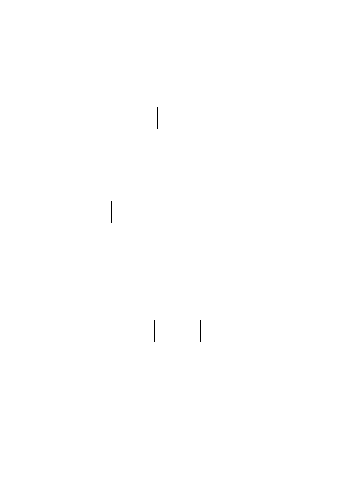
♦ Assignment blocks
Assignment blocks are used to write variables' values directly from the program. Several types of
assignments are possible as shown in the following table:
TYPE OF ASSIGNMENT EXAMPLE
Simple assignment E10=123.567
Multiple assignment E1=10, 15.5, 123.467
In multiple assignments values are loaded as follows:
10 to E1
15.5 to E2
123.467 to E3
Math expression assignment E20=(E10+125*SQR(E23))
System number SN=1.5
1-4 10 Series CNC Programming Manual (08)
Page 23

Chapter 1
Programming with 10 Series Systems
♦ Three-letter command blocks
Three-letter command blocks define an operation with a three-letter instruction in conformity with
the RS-447 standard. For example:
(ROT,45)
(DIS,"message text")
For the sake of compatibility between 10 Series and Series 8600 certain commands may be
programmed with either of the following three-letter codes.
UGS UCG
CGS CLG
DGS DCG
RQT RQU
DPA DSA
PAE ASC
PAD DSC
DPP DPT
IPB DTL
ROT URT
SOL DLO
UTO UOT
TOU TOF
10 Series CNC Programming Manual (08) 1-5
Page 24
Chapter 1
Programming with 10 Series Systems
Programmable Functions
♦ Axis coordinates
Axis coordinates can be named with letters ABCUVWXYZPQD (according to the configuration set
in AMP) and can be programmed in the following ranges:
-99999.99999 -0.00001 mm/inch
+0.00001 +99999.99999 mm/inch
NOTE:
It is impossible to program coordinates in the +0.00001 range because 0.00001 is the minimum
value accepted by the control.
♦ R coordinate
In a circular interpolation (G02 G03) R represents the radius of the circle.
In a standard canned cycle (G81-G89), the R coordinate defines the initial position value and
retract value. This function is programmable in the following ranges:
-99999.99999 -0.00001 mm/inch
+0.00001 +99999.99999 mm/inch
NOTE:
It is impossible to program values in the +0.00001 range because 0.00001 is the minimum value
accepted by the control.
In a threading block (G33), the R coordinate represents the offset from the zero angular position of
the spindle for multi-start threads.
♦ I J coordinates
In circular interpolation (G02-G03), I and J specify the coordinates of the center of an arc. I
specifies the abscissa (typically X) and J the ordinate of the center (typically Y). I and J always
specify the center coordinates regardless of the active interpolation plane.
This function is programmable in the following ranges:
-99999.99999 -0.00001 mm/inch
+0.00001 +99999.99999 mm/inch
NOTE:
It is impossible to program values in the +0.00001 range because 0.00001 is the minimum value
accepted by the control.
When the values of the corresponding axis are expressed in diametrical units (according to the
configuration set in AMP), the values of the center coordinates (I and J) are also expressed in
diametrical units.
I and J coordinates are also used in the deep hole drilling cycle (G83).
In a threading block (G33), the I address defines the pitch variation for variable pitch threads:
I+ Increasing pitch
I- Decreasing pitch
1-6 10 Series CNC Programming Manual (08)
Page 25
Chapter 1
= F
Programming with 10 Series Systems
♦ K function
In the deep hole drilling cycle (G83), K defines the incremental value to be applied to the minimum
depth value (J) in order to reduce the initial pitch depth (I).
This function is programmable in the following ranges:
-99999.99999 -0.00001 mm/inch
+0.00001 +99999.99999 mm/inch
NOTE:
It is impossible to program values in the +0.00001 range because 0.00001 is the minimum value
accepted by the control.
In a threading block (G33) or a tapping cycle (G84), K defines the thread pitch. In helical
interpolation (G02-G03), K defines the helix pitch.
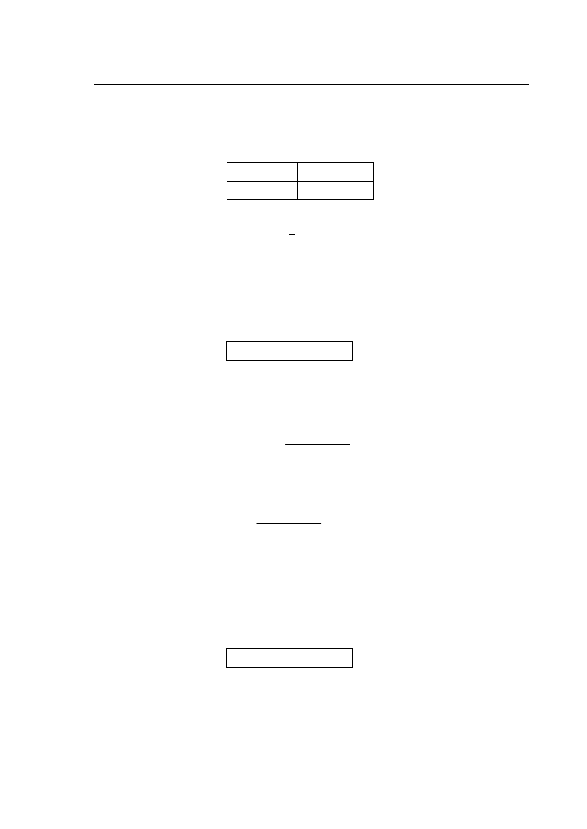
♦ F and t function
The F function defines the axes feedrate. This function is programmable in the following range:
+0.00001 +99999.99999 mm/inch
In G94, F function defines the feedrate in millimetres per minute (G71) or inches per minute (G70).
A "t" value can be programmed in a block to specify the time in seconds needed to complete the
move defined in the block. In this case the block feedrate will be:
distance total
*
time
60
A "t" value is valid only in the block in which it is programmed.
In G93, the F function defines the inverse of the necessary time in minutes to complete the
movement:
= F
speed
(minutes)1/t =
distance total
The F function is mandatory in the blocks when G93 is active and only affects that block.
In G95, F specifies the axes feedrate in millimetres per revolution (G71) or inches per revolution of
the spindle (G70).
♦ a Function
The a function defines the acceleration to use on the part program block and may be programmed
in the range:
+0.00001 +99999.99999 mm/sec
The a function is considered in mm/sec
2
or inches/sec
2
in presence of G71 and in inches/sec
2
2
in presence of
G70. This function is active only in the block it is programmed in and is in any case limited to the
acceleration on the profile as calculated by the system in function of the accelerations configured.
♦ M function
10 Series CNC Programming Manual (08) 1-7
Page 26

Chapter 1
Programming with 10 Series Systems
The M address can activate various machine operations. The programmable range goes from 0 to
999. See Chapter 6 for further information about these functions.
♦ S function
The S function specifies the spindle rotation speed. It is programmable in the following range:
+0.001 999999.999 rpm/fpm
In G97, the S function defines spindle rotation speed expressed in revolutions per minute.
In G96, the S function defines the cutting surface speed expressed in metres per minute (G71) or
feet per minute (G70). The above cutting speed remains constant on the surface.
Refer to Chapter 5 for further information about S function programming.
♦ T function
The T function defines the tool and tool offset needed for machining. It is programmable in the 0.0
to 999999999999.300 range. The 12 digits on the left of the decimal point represent the tool
identifier code and the three digits on the right represent the tool offset number.
Chapter 3 provides a detailed description of T functions.
M, S and T functions vary according to their characterisation in AMP.
IMPORTANT
From SW release 3.1 it is possible for the system to execute these functions
inside a continuous move (G27-G28).
When planning an application the manufacturer must:
• configure the desired function as "ALLOWED IN CONTINUOUS" in AMP.
• write a machine logic to handle such a function.
In turn, the programmer must remember that these functions produce different
effects depending on how they are programmed:
• in continuous mode a function configured as "ALLOWED IN CONTINUOUS"
will be executed in the sequence in which it has been programmed. In order
not to lock the program the function will be executed in "NO WAIT" mode.
• in point-to-point mode a function configured as "ALLOWED IN
CONTINUOUS" will be executed in standard mode.
♦ h functions
h functions permit to alter an offset during both continuous and point to point moves.
An h function must be programmed by itself in a block. Its value may range from 0 through 300
and may be either an integer or an E variable.
♦ G functions
G codes program machining preparatory functions for machining. The following section deal with
this codes.
1-8 10 Series CNC Programming Manual (08)
Page 27

Chapter 1
Programming with 10 Series Systems
G Codes
This section shows how to write preparatory G codes in part program blocks. A preparatory G code is
identified by the G address followed by one or two digits (G00-G99). At present, only some of the 100
possible G codes are available.
Paramacro subroutines can be called with a three-digit G code. This class of G codes is described in
Chapter 9. Three-digit G codes are classified as follows:
G100 - G299 Reserved
G300 - G599 Non modal paramacro range
G600 - G998 Modal paramacro range
G999 Reset modal paramacro
The G code must be programmed after the sequence number (if defined) and before any other
operand in the block. For example:
N100 G01 X0 - operand
It is possible to program several G codes in the same block, provided they are compatible with each
other. The table that follows defines compatibility between G codes. Zero indicates that the G codes
are compatible and can be programmed in the same block; 1 means that the G codes are not
compatible and cannot be programmed in the same block without generating an error.
10 Series CNC Programming Manual (08) 1-9
Page 28

Chapter 1
Programming with 10 Series Systems
Compatible G Codes
G 00 01 020333 818980 72
G00 1 1 1 1 0 1 1 0 0 0 0 0 0 0 0 0 0 0 1 1
G01 1 1 1 1 0 1 1 0 0 0 0 0 0 0 0 0 0 0 1 1
G02 1 1 1 1 1 1 1 0 0 0 0 0 0 0 0 0 0 0 1 1
G03 1 1 1 1 1 1 1 0 0 0 0 0 0 0 0 0 0 0 1 1
G04 0 0 0 1 1 0 1 0 0 0 0 1 0 1 1 0 0 0 1 1
G09 0 0 0 0 1 0 1 0 0 0 0 0 0 1 1 0 0 0 1 1
G16 1 1 1 1 1 1 1 1 1 1 1 1 1 1 1 1 1 1 1 1
G17 1 1 1 1 1 1 1 1 1 1 1 1 1 1 1 1 1 1 1 1
G18 1 1 1 1 1 1 1 1 1 1 1 1 1 1 1 1 1 1 1 1
G19 1 1 1 1 1 1 1 1 1 1 1 1 1 1 1 1 1 1 1 1
G27 0 0 0 0 1 0 1 0 0 0 0 1 1 1 0 0 0 0 1 1
G28 0 0 0 0 1 0 1 0 0 0 0 1 1 1 0 0 0 0 1 1
G29 0 0 0 0 1 0 1 0 0 0 0 1 1 0 0 0 0 0 1 1
G33 1 1 1 1 1 1 1 0 0 1 1 0 0 0 0 0 0 0 1 1
G40 0 0 0 1 1 1 1 0 0 1 1 0 0 0 0 0 1 0 1 1
G41 0 0 0 1 1 1 1 0 0 1 1 0 0 0 0 0 1 0 1 1
G42 0 0 0 1 1 1 1 0 0 1 1 0 0 0 0 0 1 0 1 1
G70 0 0 0 0 0 0 1 0 0 0 0 0 0 0 0 0 0 1 1 1
G71 0 0 0 0 0 0 1 0 0 0 0 0 0 0 0 0 0 1 1 1
G72 1 1 1 1 1 1 1 1 1 1 1 1 1 1 1 1 1 1 1 1
G73 1 1 1 1 1 1 1 1 1 1 1 1 1 1 1 1 1 1 1 1
G74 1 1 1 1 1 1 1 1 1 1 1 1 1 1 1 1 1 1 1 1
G79 0 0 0 0 1 1 1 0 0 1 1 0 0 0 0 1 1 0 1 1
G80 1 1 1 1 1 1 1 0 0 1 1 0 0 0 0 0 1 0 1 1
G81 0 0 1 1 1 1 1 0 0 1 1 1 1 1 1 0 1 0 1 1
G82 0 0 1 1 1 1 1 0 0 1 1 1 1 0 0 0 1 0 1 1
G83 0 0 1 1 1 1 1 0 0 1 1 1 1 0 0 0 1 0 1 1
G84 0 0 1 1 1 1 1 0 0 1 1 1 1 0 0 0 1 0 1 1
G85 0 0 1 1 1 1 1 0 0 1 1 1 1 0 0 0 1 0 1 1
G86 0 0 1 1 1 1 1 0 0 1 1 1 1 0 0 0 1 0 1 1
G89 0 0 1 1 1 1 1 0 0 1 1 1 1 0 0 0 1 0 1 1
G90 0 0 0 0 0 0 1 0 0 0 0 0 0 0 0 1 1 0 1 1
G91 0 0 0 0 0 0 1 0 0 0 0 0 0 0 0 1 1 0 1 1
G92 1 1 1 1 1 1 1 1 1 1 1 1 1 1 1 1 1 1 1 1
G93 0 0 0 0 0 0 1 1 0 0 0 0 0 0 0 0 0 0 1 1
G94 0 0 0 0 0 0 1 1 0 0 0 0 0 0 0 0 0 0 1 1
G95 0 0 0 0 0 0 1 1 0 0 0 0 0 0 0 0 0 0 1 1
G96 0 0 0 0 0 0 1 0 1 0 0 0 0 0 0 0 0 0 1 1
G97 0 0 0 0 0 0 1 0 1 0 0 0 0 0 0 0 0 0 1 1
G99 1 1 1 1 1 1 1 1 1 1 1 1 1 1 1 1 1 1 1 1
73
74
93
9697414240 272829 04 09 909179 707116
94
95
17
18
19
92
99
NOTE:
0 means compatible G codes
1 means incompatible G codes
1-10 10 Series CNC Programming Manual (08)
Page 29

Chapter 1
Programming with 10 Series Systems
The following table gives a summary of the G codes available in the control. This default configuration
can be modified through the AMP utility.
G code summary
CODE GROUP MODAL DESCRIPTION POWER UP
MILL GRINDING
G00 a yes Rapid axes positioning yes yes
G01 a yes Linear interpolation no no
G02 a yes Circular interpolation CW no no
G03 a yes Circular interpolation CCW no no
G33 a yes Constant or variable pitch thread no no
G16 b yes Circular interpolation and cutter diameter
compensation on a defined plane
G17 b yes Circular interpolation and cutter diameter
compensation on 1st-2nd axes plane
G18 b yes Circular interpolation and cutter diameter
compensation on 3rd-1st axes plane
G19 b yes Circular interpolation and cutter diameter
compensation on 2nd-3rd axes plane
G27 c yes Continuous sequence operation with yes yes
automatic speed reduction on corners
G28 c yes Continuous sequence operation no no
without speed reduction on corners
G29 c yes Point-to-point operation no no
G92 d no Axis presetting no no
G99 d yes Delete G92 yes yes
G40 e yes Cutter diameter compensation disable yes yes
G41 e yes Cutter diameter compensation-tool left no no
G42 e yes Cutter diameter compensation-tool right no no
G20
G21
yes
yes
Closes GTL profile
Opens GTL profile
no no
yes no
no yes
no no
G60 yes Closes the HSM profile no no
G61 yes Opens the HSM profile no no
G62 no Splits the HSM profile in two with
continuity
G63 no Splits the HSM profile in tw with link no no
G66 no Splits the HSM profile in two with edge no no
G67 no Splits the HSM profile in two with
reduced speed on edge
10 Series CNC Programming Manual (08) 1-11
no no
no no
Page 30

Chapter 1
Programming with 10 Series Systems
CODE GROUP MODAL DESCRIPTION POWER UP
MILL GRINDING
G70 f yes Programming in inches no no
G71 f yes Programming in millimetres yes yes
G80 g yes Disable canned cycles yes yes
G81 g yes Drilling cycle no no
G82 g yes Spot-facing cycle no no
G83 g yes Deep hole drilling cycle no no
G84 g yes Tapping cycle no no
G85 g yes Reaming cycle no no
G86 g yes Boring cycle no no
G89 g yes Boring cycle with dwell no no
G90 h yes Absolute programming yes yes
G91 h yes Incremental programming no no
G79 i no Programming referred to axis no no
home switch
G04 j no Dwell at end of block no no
G09 j no Deceleration at end of block no no
G72 k no Point probing with probe tip no no
radius compensation
G73 k no Hole probing with probe tip no no
radius compensation
G74 k no Probing for theoretical deviation from a
point without probe tip radius
compensation
G93 l yes Inverse time (V/D) feedrate no no
programming mode
G94 l yes Feedrate programming in ipm or mmpm yes no
G95 l yes Feedrate programming in ipr or mmpr no yes
G96 m yes Constant surface speed (feet per no yes
minute or metres per minute)
G97 m yes Spindle speed programming in rpm yes no
no no
1-12 10 Series CNC Programming Manual (08)
Page 31

Chapter 1
Programming with 10 Series Systems
SYNCHRONISATION AND PROGRAM EXECUTION
The terms "synchronised" and "asynchronised" apply only to part program blocks that do not imply a
movement, that is, assignment or calculation blocks. A motion block is any block containing axes
motion together with other actions:
• Axis moves
• M codes
• S codes
• T codes
A synchronisation block is taken into consideration and executed only after the motion block that
precedes it in the program is completed, that is after the axis move has been executed.
On there other hand, a non-synchronised block is executed as soon as it is read by the part program
interpreter, i.e. when perhaps the previous move is still in progress.
The advantage of asynchronous block execution is that variable assignments and complex
calculations can be made between moves. This allows to reduce waiting time between two motion
blocks caused by calculations.
Default Synchronisation
At power up, the following commands and codes are automatically synchronised:
• UDA, SCF, RQO, IPB, DLY, WOS, WAI, SND, GTA, REL, UPR, TCP, UVP, UVC
• G16, G17, G18, G19, G72, G73, G74
All the other commands are not synchronised.
This default assignment can be changed. This means that the commands that are synchronised by
default at power-up can become asynchronous and that the commands that are not synchronised by
default at power-up can become synchronous. The next section explains how to override default
synchronisation.
NOTE:
Default synchronisation cannot be modified for GTA, UPR, TCP, UVP, and UVC instructions.
10 Series CNC Programming Manual (08) 1-13
Page 32

Chapter 1
Programming with 10 Series Systems
Overriding Default Synchronisation
Under certain circumstances, the part program may request to modify the default synchronisation.
If the command is synchronised by default and the programmer wants it to be executed by the
interpreter as soon as it is read (asynchronous operation), an "&" must be programmed in the first
position of the block, immediately after the "n" number.
If the command is asynchronous and you wish to activate synchronous operation, the first character
in the block must be #.
Both # and & are active only in the block where they are programmed.
To avoid possible damage to the workpiece, note that programming
synchronised blocks between contouring blocks clears the motion buffer at each
synchronised block. This will result in dwells while the buffer is reloaded and all
WARNING
the calculations are performed.
Part Program Interpreter
When the system reads a part program block it executes various activities, depending on the type of
block:
• A motion block will be loaded in the motion buffer queue. If the move is defined by a variable, the
stored move values stored are those of the variable. The buffer size is configurable from 2 to 64
blocks through AMP.
• An asynchronous assign or calculation block will be executed.
Three factors cause the part program interpreter to stop reading blocks:
• The motion buffer is full. When the active motion block is completed, the interpreter will read
another motion block and load it in the buffer queue.
• A non-motion block that contains a synchronised command or a code that forces synchronisation
is read. The interpreter does not start again until the last loaded motion block is completed. At
this point the block calling for synchronisation is executed and the interpreter starts reading the
following blocks.
• Error conditions
1-14 10 Series CNC Programming Manual (08)
Page 33

Sequence of execution
1. Diameter axes
2. Scale factors (SCF)
3. Measuring units (G70 G71)
4. Paraxial compensation ( u v w )
5. Inch/metric programming (G90 G91)
6. Mirror machining (MIR)
7. Plane rotation (ROT)
8. Origins (UAO UTO UIO G92)
Programming restrictions for long real (double) formats
The following restrictions apply to long real programming:
Chapter 1
Programming with 10 Series Systems
• Max. 15 numbers in total
• Max. 12 integer digits
• Max. 9 decimal digits
The system will display an error if more than 12 integer digits are programmed.
If more than 9 decimal numbers are programmed, the system does not display any error but cuts off
the programmed number at the last allowed digit.
10 Series CNC Programming Manual (08) 1-15
Page 34

Chapter 1
Programming with 10 Series Systems
END OF CHAPTER
1-16 10 Series CNC Programming Manual (08)
Page 35

Chapter
2
PROGRAMMING THE AXES
AXIS MOTION CODES
Defining Axis Motion
In this manual axes motion directions are defined in compliance with EIA standard RS-267. By
convention, we always assume that the tool moves towards the part, no matter whether the tool
moves towards the part or the part moves towards the tool in the actual process.
Basic movements can be defined with the motion G codes listed in the following table:
G CODE FUNCTION
G00 Rapid axes positioning
G01 Linear interpolation
G02 Circular interpolation clockwise
G03 Circular interpolation counter clockwise
G33 Constant or variable pitch threading
10 Series CNC Programming Manual (10) 2-1
Page 36

Chapter 2
Programming the Axes
G00 - Rapid Axes Positioning
G00 defines a linear movement at rapid feedrate that is simultaneous and coordinated for all the axes
programmed in the block.
Syntax
G00 [G-codes] [axes] [offset ] [F..] [a] [auxiliary]
where:
G-codes Other G codes that are compatible with G00 (See "Compatible G codes" table in
Chapter 1).
axes Axis name followed by a numerical value. The numerical value can be programmed
directly with a decimal value or indirectly with an E parameter. Up to six axes can be
written in a block.
offset Offset factors on the profile. For the X, Y, Z axes these factors are entered with u, v, and
w respectively. See "Paraxial compensation" in Chapter 4 for further information.
F Feedrate for coordinated moves. It is given with the F address followed by the feedrate
value. This parameter does not affect the move of the axes programmed in the G00
block, but is retained for subsequent feedrate moves. The rapid feedrate forced by G00
is a velocity along the vector of the axes programmed in the block. The maximum rapid
feedrate is defined during characterisation with the AMP utility.
a Acceleration to be used on the profile.
auxiliary Programmable M, S, and T auxiliary functions. Up to four M functions, one S (spindle
speed) and one T (tool selection) can be programmed in the block.
2-2 10 Series CNC Programming Manual (10)
Page 37

Chapter 2
Programming the Axes
G01 - Linear Interpolation
G01 defines a linear move at machining feedrate that is simultaneous and coordinated on all the axes
programmed in the block.
Syntax
G01 [G-codes] [axes] [offset ] [F..] [a] [auxiliary]
where:
G-codes Other G codes that are compatible with G01 (See "Compatible G codes" table in
Chapter 1).
axes Axis name followed by a numerical value. The numerical value can be programmed
directly with a decimal value or indirectly with an E parameter. Up to six axes can be
offset Offset factors on the profile. These factors are entered for the X, Y, Z axes with the
characters u, v, w respectively. See "Paraxial compensation" in Chapter 4 for further
information.
F Feedrate used for the move. It is given with the F address followed by the feedrate value.
If omitted, the system will use the previously programmed feedrate. If no feedrate has
been programmed the control will generate an error.
a Acceleration to be used on the profile.
auxiliary Programmable M, S, T auxiliary functions. Up to four M functions, one S (spindle
speed) and one T (tool selection) can be programmed in the block.
Example:
This example shows how to program a G01 code.
Y
40
Program:
N60 (UGS,X,-10,100,Y,-10,50)
N70 G0 X10 Y10
N80 G01 X90 Y40 F200
10
0
0
10
90
x
10 Series CNC Programming Manual (10) 2-3
Page 38

Chapter 2
Programming the Axes
G02 G03 - Circular Interpolation
These codes define the following circular movements:
G02 Circular interpolation clockwise (CW)
G03 Circular interpolation counter clockwise (CCW)
The circular move is performed at machining feedrate and is coordinated and simultaneous with all the
axes programmed in the block.
Syntax
G02 [G-codes] [axes] I.. J.. [F..] [a] [auxiliary]
or
G02 [G-codes] [axes] R.. [F..] [a] [auxiliary]
G03 [G-codes] [axes] I.. J.. [F..] [a] [auxiliary]
or
G03 [G-codes] [axes] R.. [F..] [a] [auxiliary]
where:
G-codes Other G codes that are compatible with G02 and G03 (See "Compatible G codes" table
in Chapter 1).
axes Axis name followed by a numerical value programmed directly with a decimal value or
indirectly with an E parameter.
If axes are not programmed in the block, the move is a complete circle in the active
interpolation plane.
I Abscissa of the circle centre. This is a value in millimetres that can be programmed
directly or indirectly with an E parameter. The abscissa is expressed as a diameter unit
when the corresponding axis is a diameter axis. No matter what interpolation plane you
are using, the symbol for the abscissa is always I.
J Ordinate of the circle centre. This is a value in millimetres that can be programmed
directly or indirectly with an E parameter. The ordinate is expressed as a diameter unit
when the corresponding axis is a diameter axis. No matter what interpolation plane you
are using, the symbol for the ordinate is always J.
NOTE: The parameter R cannot be used for arcs of 360 degrees..
2-4 10 Series CNC Programming Manual (10)
Page 39

Chapter 2
Programming the Axes
R Circle radius alternative to the I and J coordinates. If the arc of a circle is less than or
equal to 180 degrees, the radius must be programmed with positive sign; if the arc of a
circle is greater than 180 degrees the radius must be programmed with negative sign.
NOTA: R is not allowed with arc of 360 degrees.
F Feedrate used for the move. It is given with the F address followed by the feedrate value.
If omitted, the system will use the programmed value. If no feedrate has been
programmed an error will occur.
a Acceleration to be used on the profile.
auxiliary Programmable auxiliary functions M, S, T. Up to four M functions, one S (spindle speed)
and one T (tool selection) can be programmed in the block.
Characteristics:
The maximum programmable arc is 360 degrees, i.e. a full circle. Before programming a circular
interpolation block, the interpolation plane must be defined with G16, G17, G18, G19. G17 is
automatically active after power up.
The coordinates of the start point (determined from the previous block), the end point and the centre
of the move must be calculated so that the difference between start and end radius is less than the
default value (0.01 mm or 0.00039 inches). If this difference is equal or greater than the default value,
the control displays an error message and the circular move is not performed.
Incremental programming (G91) can be used in conjunction with circular interpolation. With G91 the
end point and the centre point of the circular move are referenced to the start point programmed in the
previous block.
The direction (CW or CCW) of a circular interpolation is defined by looking in the positive direction of
the axis that is perpendicular to the active interpolation plane.The following examples show the
directions for circular interpolation on the active planes.
Z
G02
XY
G02
G03
ZX
G03
Y
G02
G03
Z
Y
X
Directions of a circular interpolation
10 Series CNC Programming Manual (10) 2-5
Page 40

Chapter 2
Programming the Axes
Circular interpolation in absolute programming with the I and J coordinates of the centre of the circle.
N14 X10 Y20
N15 G2 X46 Y20 I28 J20 F200
N16 G3 X64 Y38 I46 J38
G02
G03
0
28
46
64
38
20
0
X
Circular interpolation in absolute programming with the value R of the radius of the circle.
N14 X10 Y20
N15 G2 X46 Y20 R18 F200
N16 G3 X64 Y38 R18
Circular interpolation in incremental programming with the coordinates J and I.
N14 X10 Y20
N15 G2 X46 G91 X36 I18 J0 F200
N16 G3 X18 Y18 I0 J18
Circular interpolation in incremental programming with the value of the radius R.
N14 X10 Y20
N15 G2 G91 X36 R18 F200
N16 G3 X18 Y18 R18
2-6 10 Series CNC Programming Manual (10)
Page 41

Chapter 2
Programming the Axes
CET (PRC) - Circular Endpoint Tolerance
In circular interpolations, CET defines the tolerance for the variance between the starting and final
radiuses of the circle arc.
Syntax
CET=value
where:
value Tolerance expressed in millimetres. The default value is 0.01 mm.
Characteristics:
If the difference between starting and final radius is smaller than the tolerance but not zero, the
system normalises the circle data according to the values specified in CET and ARM.
If the difference is equal to or greater than the value assigned to CET, an error occurs and the
programmed final points will not be executed. In this case, you must either modify the program or
increase the CET tolerance.
The value assigned to CET can be modified as follows:
• In the AMP configuration
• By means of a specific data entry
• By writing a new CET in the part program.
The CET tolerance is always expressed in the characterised measuring unit (G70/G71 apply).
If the variance between programmed start and final radius is higher than the CET value, the circle arc
can be executed as follows:
• By making the CET value greater than the actual variance
• By programming the arc with the circle radius rather than with the centre using this format:
G2/G3, final point and R radius
A RESET re-establishes the default tolerance.
Example:
CET=0.02 defines a 0.02 mm tolerance
10 Series CNC Programming Manual (10) 2-7
Page 42

Chapter 2
Programming the Axes
FCT - Full Circle Threshold
In a circular interpolation, the FCT instruction defines a threshold for the distance between the first
and the last point in an arc. Within this distance the arc is considered a full circle.
Syntax
FCT=value
where:
value Threshold expressed in millimetres. The default value is 0.001 mm.
Characteristics:
The FCT command allows to deal with inaccurate program data that would otherwise prevent the
system from forcing a complete circle. In other words, if the distance from the first to the last point is
less than FCT, the system uses the points as if they were overlapping and forces a full circle.
FCT thresholds can be modified as follows:
• In the AMP configuration
• By means of a specific data entry
• By writing a new CET in the part program.
The FCT threshold is always expressed in the characterised measuring unit (G70/G71 apply).
A RESET re-establishes the default threshold.
Example:
G71
FCT=0.005
In this example, FCT defines a threshold 0.005 millimetres.
2-8 10 Series CNC Programming Manual (10)
Page 43

Chapter 2
Programming the Axes
ARM - Defining Arc Normalisation Mode
The ARM code defines the method with which the system normalises an arc (programmed with the
centre coordinates I and J, and a final point) in order to render it geometrically congruent.
An arc is normalised when the variance between initial and final radius is less than the characterised
accuracy tolerance or than the tolerance programmed with the CET command.
Before executing an arc, the system calculates the difference between initial and final radiuses.
• If the difference is zero, the control will execute the programmed arc without normalising it.
• If the difference is greater than the CET value, the control will stop without executing the move,
and display a profile error message.
• If the difference is less than the CET value, the control will execute the move normalising the arc
with the method specified by ARM.
• If the distance is less than the FCT threshold, the system will force the complete circle. For ISO
blocks with radius compensation, the system checks the difference twice: first on the base profile
without compensation (normalisation stage) and then on the compensated profile (motion
generation stage).
Syntax
ARM=arc mode
where:
arc mode Is the numerical value that defines the arc normalisation mode.
Valid values are:
0 displaced centre within the CET tolerance (default mode)
1 displaced starting point displaced the CET tolerance
2 displaced centre independent from the CET tolerance
3 centre beyond the CET tolerance range
The default value is zero.
Characteristics:
The arc normalisation mode can be modified as follows:
• In the AMP configuration
• By means of a specific data entry
• By writing a new CET in the part program.
The examples that follow illustrate ARC normalisation modes.
10 Series CNC Programming Manual (10) 2-9
Page 44

Chapter 2
Programming the Axes
ARM=0
This is an arc through the initial and final programmed points whose centre is displaced within the
tolerance defined by CET. The arc is executed with averaged radius.
starting point
CET
averaged radius
CS
C
CET
final point
C = programmed center
CS= displaced center
ARM=1
This is an arc through the programmed final point and the starting point displaced within the CET
tolerance. The arc is executed with final radius.
starting point
CET
C
final point
C= programmed center
2-10 10 Series CNC Programming Manual (10)
Page 45

Chapter 2
Programming the Axes
ARM=2
This is an arc whose centre is displaced irrespective of the tolerance defined with CET. In this case
the arc is executed with averaged radius.
CET
CET
C
starting point
CS
arc with averaged radius
final point
C= programmed center
CS = displaced center
ARM=3
If the displacement of the centre arc is within the CET tolerance defined with CET, the arc centre will
be displaced and the arc will pass through the programmed starting and final points. If the
displacement of the centre is not within the CET tolerance, the arc will have the programmed centre
and pass through the displaced starting and final points (both points are displaced within the CET/2
tolerance).
In this case the arc is executed with averaged radius.
CET
starting point
CCSCET
A
C = programmed center
CS = displaced center
averaged radius
final point
CET
CET
B
starting point
arc with averaged
radius plus initial
and final steps
C
CS
final point
10 Series CNC Programming Manual (10) 2-11
Page 46

Chapter 2
Programming the Axes
IMPORTANT
With ARM = 1 or ARM = 3 the resultant profile can show inaccuracies ("steps"):
With ARM = 1 there will be a step at circle start equal to the difference between
starting and final radiuses.
In case of ARM = 3 there will be a step both at circle arc start and end.
To prevent these steps from causing a servo error, we suggest that you program a
CET value smaller than the characterised servo error threshold.
2-12 10 Series CNC Programming Manual (10)
Page 47

Chapter 2
Crt = 1
R
Programming the Axes
CRT - Circular interpolation speed reduction threshold
CRK - Circular interpolation speed reduction constant
The variables CRT (Circle Reduction Threshold) and CRK (Circle Reduction K-Constant) are used for
reducing the speed on circular elements according to the radius of the circle.
Sintiaxi
CRT = value
where:
value is the threshold radius below which the reduction is to be applied. The value 0
(zero), which is set by default, cancels the function.
CRK = value
where:
value is a constant for modulating the reduction in speed. The value set by default is 1.
Characteristics:
By assigning any value other than 0 to the variable CRT, the speed is reduced on all circular elements
with a smaller radius than the value set. The value assigned to the variable CRK enables this reduction to
be modulated. The speed is reduced as shown in the graph below, in which it is assumed that the
programmed speed Vp is equal to 1 and the variable CRT is equal to 1.
V
Vp = 1
Crk
0.606
2.718
0.135
0.5
1
2
4
0.018
10 Series CNC Programming Manual (10) 2-13
Page 48

Chapter 2
Programming the Axes
The values assigned to the variables CRT and CRK may be modified as follows
• by means of the AMP command during configuration
• from the part program with the specified syntax.
The values assigned to CRT are always expressed in the current unit of measurement of the process
(the G70/G71 functions are applied).
The RESET command restores the characterization values.
2-14 10 Series CNC Programming Manual (10)
Page 49

Chapter 2
Programming the Axes
Helical Interpolation
G02 and G03 program a helical path in only one block. The system performs the helical path by
moving the plane axes in a circular interpolation while the axis that is perpendicular to the
interpolation plane moves linearly.
To program a helical path, simply add a depth coordinate and the helix pitch (K) to the parameters
specified in the circular interpolation block.
Syntax
G02 [G-codes] [axes] I.. J.. K.. [F..] [auxiliary]
or
G02 [G-codes] [axes] R.. K.. [F..] [auxiliary]
G03 [G-codes] [axes ] I.. J.. K.. [F..] [auxiliary]
or
G03 [G-codes] [axes ] R.. K.. [F..] [auxiliary]
where:
G-codes Other G codes that are compatible with G02 and G03 (See "Compatible G codes "
table in Chapter 1).
axes An axis letter followed by a numerical value programmed (either decimal value or
E parameter).
If no axes are programmed in the block, the move will generate a full circle on the
active interpolation plane.
I Abscissa of the circle centre. This is a value in millimetres (decimal number or E
parameter). The abscissa is expressed as a diameter unit when the
corresponding axis is a diameter axis. No matter what the interpolation plane, the
symbol for the abscissa is always I.
J Ordinate of the circle centre. This is a value in millimetres (decimal number or E
parameter). The ordinate is expressed as a diameter unit when the corresponding
axis is a diameter axis. No matter what the interpolation plane, the symbol for the
ordinate is always J.
10 Series CNC Programming Manual (10) 2-15
Page 50

Chapter 2
Programming the Axes
R Circle radius. It is specified with the R address followed by a length value, and is
alternative to the I and J coordinates.
K Helix pitch. This parameter is specified with the K address followed by the pitch
value. It can be omitted if the helix depth is less than one pitch.
F Feedrate. It is specified by the F address followed by a value. If it is omitted, the
system will use the previously programmed feedrate. If no feedrate has been
programmed, the system will signal an error.
auxiliary Programmable M, S, and T functions. Up to four M functions, one S (spindle
speed) and one T (tool selection) can be programmed in the block.
Characteristics:
If Z is a multiple of K, it is not necessary to program the final point
If the depth is not an integer number of pitches, i.e. if Z is not equal to n * K), the length of the circle
arc must be calculated with the decimal remainder of the pitch number. For example, if Z = 2.7 * K,
then the arc that must be programmed is 360 * (2.7 - 2) = 252 degrees.
Example:
G2 X . . Y. . Z . . I . . J . . K . . F. .
In this example, addresses X, Y, I, and J refer to circle programming; addresses Z and K refer to helix
programming and are respectively the depth and the helix pitch. The figure below shows the typical
dimensions of a helical interpolation.
Dimensions Helix
2-16 10 Series CNC Programming Manual (10)
Page 51

Chapter 2
Programming the Axes
G33 - Constant or Variable Pitch Threading
G33 defines a cylindrical, taper, or face threading movement with constant or variable pitch. The
threading move is synchronised to spindle rotation. The parameters programmed in the block identify
the type of thread.
Syntax
G33 [axes] K.. [I..] [R..]
where:
axes An axis letter followed by a numerical value.
K Thread pitch (mandatory). For variable pitch threads, K is the initial pitch.
I Pitch variation for variable pitch threading. For increasing pitch threading, I must
be positive; for decreasing pitch threading I must be negative.
R Deviation from the zero spindle angular position in degrees. R is used in multistart
threading to avoid displacing the starting point.
Characteristics:
All these numerical values can be programmed directly with decimal numbers or indirectly with E
parameters.
In decreasing pitch threads, the initial pitch, the pitch variation, and the thread length must be
calculated so that the pitch is greater than zero before reaching the final coordinate. Use the following
formula:
2
K
I <
2 (Zf - Zi)
where:
I Is the maximum pitch variation
K Is the initial pitch
(Zf - Zi) Is the thread length.
IMPORTANT
10 Series CNC Programming Manual (10) 2-17
During the threading cycle the control ignores the CYCLE STOP button and the
FEEDRATE OVERRIDE selector/softkey, whereas the SPINDLE SPEED
OVERRIDE selector must be disabled by the machine logic.
VFF may be disabled with the dedicated softkey or with a VFF command.
Page 52

Chapter 2
Programming the Axes
Constant Pitch Threading
The figures that follow illustrate examples of constant pitch threading. Note that the U axis is a
diameter axis.
Cylindrical threading
U
Conical threading
U
Z
K2
Z-100
Z
K3
Z-80
U40
Part program block: G33 Z-100 K2
Part program block: G33 U40 Z-80 K3
Cylindrical-conical threading
Part program blocks: G33 Z-95 K2 .5
Z-100 U52 K2.5
U52
2-18 10 Series CNC Programming Manual (10)
Page 53

Chapter 2
Programming the Axes
Variable Pitch Threading
The figures that follow illustrate variable pitch threading. Note that the U axis is a diameter axis.
Cylindrical threading with increasing pitch
Z
4
5
6
7
8
9
Part program block: G33 Z-50 K4 I1
Conical threading with increasing pitch
Z
U
4
5
6
7
8
9
Part program block: G33 U50 Z-40 K4 I1
Cylindrical thread with decreasing pitch
U
10
9
8
7
6
5
4
Z
Part program block: G33 Z-50 K10 I-1
10 Series CNC Programming Manual (10) 2-19
Page 54

Chapter 2
Programming the Axes
Multi-start threading
An R word in a G33 block makes the control start moving the axes from an angular position that
varies according to the programmed R value.
This permits to program the same start point for all threads, rather than move the start point of each
thread by a distance equal to the pitch divided by the number of starts.
Example:
Three-start threading
N37 G33 Z3 K6 1st thread
.
.
.
N41 G33 Z3 K6 R120 2nd thread
.
.
.
N45 G33 Z3 K6 R240 3rd thread
2-20 10 Series CNC Programming Manual (10)
Page 55

Chapter 2
Programming the Axes
Rotary Axes
In the system characterisation, axes can be configured as rotary axes, i.e. a rotary table.
To program rotary axis moves simultaneous to and coordinated with the other axes programmed in
the same block:
• Always use decimal degrees (from +0.00001 to +99999.99999 degrees) starting from a pre-
selected origin.
• Select either the rapid rate (G00) or the feedrate (G01). In a rotary move rates are always
expressed in degrees per minute (dpm, F5.5 format). For example, with F75.5 the axis moves at
75.5 dpm.
To perform milling operations on a circle with a rotary table, calculate the rotary rate with the following
formula.
360
F =
A
*
D
= 114,64
pi
*
A
D
where:
F Is the rotary rate in dpm
A Is the linear rate on the arc in millimetres or inches per minute
D Is the diameter on which the milling operation is performed (in mm or inches).
To move rotary and linear axes simultaneously in the same block, you may calculate the feedrate
with one of the following formulas.
With G94:
F = A *
where:
F Is the feedrate
A Is the feedrate on the part (in mm/min or inches/min)
X Y Z B C Is the actual travel performed by each axis (in mm or inches for linear axes, in
degrees for rotary axes)
L Is the resultant path length (in mm or inches).
X2+Y2+Z2+B2+C
L
2
10 Series CNC Programming Manual (10) 2-21
Page 56

Chapter 2
Programming the Axes
With G93:
F =
A
X2 + Y2 + B
2
where:
F Is the feedrate
A Is the desired feedrate (in mm/min or inches/min) on the part
X Is the X axis incremental distance
Y Is the Y axis incremental distance
B Is the B axis incremental distance
The control cannot calculate the desired tool feedrate directly because the radius is not programmed.
In these cases, the feedrate can be specified as inverse time with G93.
A block moving only the rotary axes generates an arc. If rotary and linear moves are combined, the
resulting path may be an Archimedean spiral, a cylindrical helix or more complex curves, depending
on the programmed number of linear axes.
2-22 10 Series CNC Programming Manual (10)
Page 57

Chapter 2
Programming the Axes
Axes with Rollover
Axes with rollover axis are rotary or linear axes whose position is controlled between zero and a
positive value configured in the rollover pitch parameter.
In the following description the axsi with rollover is rotary and has a 360 degree rollover pitch. We
assume that the axis position is controlled in the 0 to 359.9999 degree range. That is, when the axis
reaches 360 degrees, the displayed position rolls over to zero degrees.
An axis with rollover can be programmed in a block or in a MDI in two different modes:
absolute mode (G90) programs the move in degrees.
incremental mode (G91) programs the move as increments in degrees from the current
axis position.
G90 - Absolute mode
In this mode:
• Displayed position is from 0 to +359.99999 degrees
• Programmed range is from 0 to ± 359.99999 degrees
• Direction of axis rotation depends on the sign of the programmed move. By convention, a positive
move is clockwise and a negative move is counter clockwise.
10 Series CNC Programming Manual (10) 2-23
Page 58

Chapter 2
Programming the Axes
For example, let's assume that rotary axis B is positioned at 90 degrees and the following block is
written in the part program or in an MDI:
G90 B45
180
90
359.999
0
45
Clockwise Rotation
The B axis rotates by 315 degrees clockwise from the 90 degree position to reach the absolute
position of 45 degrees (the sign of the move is positive).
Now let's assume that the B rotary axis is at 90 degrees and, the following block is written in the part
program or in an MDI:
G90 B-0
0
90
Counter clockwise Rotation
The B axis rotates by 90 degrees counterclockwise to absolute position 0 degrees because the sign
of the move is negative.
2-24 10 Series CNC Programming Manual (10)
Page 59

Chapter 2
Programming the Axes
G91 - Incremental mode
When an axis with rollover is programmed in incremental (G91) mode, the following conditions apply:
• Displayed position is from 0 to +359.99999 degrees.
• Program range is from +/-0.00001 to +/-99999.99999 degrees.
• Direction of axis rotation depends upon the sign of the programmed move. By convention, a
positive move is clockwise and a negative move is counter clockwise.
IMPORTANT
range is greater than +359.999 degrees.
For example, if the absolute zero position of the B rotary axis is 0 degrees and the following block is
written in the part program or in an MDI:
G91 B765
0
45
The displayed position is beyond the programmed range when the programmed
90
Incremental clockwise rotation
The B axis makes two complete clockwise revolutions plus 45 degrees (360 + 360 + 45 = 765).
10 Series CNC Programming Manual (10) 2-25
Page 60

Chapter 2
Programming the Axes
Pseudo Axes
A pseudo axis is an auxiliary function that may be addressed as an axis and is handled by the
machine logic. The pseudo axis name can be any allowed axis name (X,Y,Z,A,B,C,U,V,W,P,Q,D). In
a part program block it is possible to program up to 3 pseudo axes but in the AMP it is possible to
configure up to 6 pseudo axes.
Diameter Axes
A reaming/facing head can be mounted on the spindle and controlled simultaneously with other axes.
By programming such an axis (typically a U axis) as a diameter, the following can be obtained:
• Boring operations on cylindrical or conical holes
• Circular radiuses (concave or convex)
• Chamfers
• Grooves
• Facing operations
• Threads
Programming a U (diameter) axis is similar to programming other linear axes; however, its
coordinates must be expressed in diameters. The measuring units can be inches or millimetres
according to the current mode ( G70/G71).
When the U axis is programmed in the same block as an X, Y or Z move, it is simultaneous with and
coordinated to the other axes. U axis moves can be performed at rapid rate (G00) or feedrate (G01)
with F in ipm or mmpm.
Before executing a profile with the U axis, the interpolation plane must be defined with the following
command:
G16 Z U
IMPORTANT
The order of Z and U in this command is critical, i.e. G16 UZ and G16 ZU define two
different interpolation planes.
Cutter diameter compensation (G41 or G42) and a machining allowance (MSA) can
be applied to profiles programmed with U.
2-26 10 Series CNC Programming Manual (10)
Page 61

Example:
This is an example reaming/facing head used in a finishing operation.
Chapter 2
Programming the Axes
N116 (DIS, "FINISHING WITH R/F HEAD")
N117 F60 S630 T9 .9 M6
N118 G16 Z U ;Defines interpolation plane
N119 (UAO, 2) ;Calls absolute origin for the head
N120 (UTO, 1, Z-200) ;Temporary origin for Z (skimming the part)
N121 X Y160 M3 ;Position to hole 1
N122 G41 Z2 U51
N123 G1 Z-1 U44 .98 ;Executes the chamfer
N124 Z-44 ;Executes hole diameter 45
N125 G G40 U40
N126 Z2 F40 S380
N127 G41 Y U106 ;Positions to hole 2
N128 G1 Z-1 U99 .975 ;Executes the chamfer
N129 Z-15 ;Executes hole diameter 100
N130 r5 ;Executes radius R = 5
N131 U60 ;Executes counter boring
N132 r-3 ;Executes radius R = 3
N133 Z-40 U40 ;Executes taper
N134 G40 Z-44 ;Continues Z axis travel
N135 G U35
N136 Z100 M5
N137 G16 X Y
N138 (UAO,1)
10 Series CNC Programming Manual (10) 2-27
Page 62

Chapter 2
Programming the Axes
The direction of the arcs programmed with G02/G03 or with the r address and the direction for cutter
diameter compensation (G41/G42) can be determined by looking at the profile on the Z-U plane.
Since negative diameters are usually not programmed, you must consider only the first two quadrants
of the plane.
2-28 10 Series CNC Programming Manual (10)
Page 63

Chapter 2
Programming the Axes
UDA - Dual Axes
It is possible to treat one or more axes as slaves or subordinate to another defined as the master. In
this way only the movements of the Master need be programmed as the movement of the slaves is
determined by those of the Master to which they are associated and by whether or not reverse mirror
movement has been applied.
Syntax
(UDA,master1/slave1[,master2/slave2,master3/slave3,master4/slave4])
(UDA)
where:
master1. . . master4 Are the master axis names (one ASCII character per axis). You can
program up to 4 master axes.
slave1. . . slave8 Are the slave axes names (one ASCII character per axis). You can program
a maximum of 8 slave axes per master.
no parameters (UDA) without parameters disables the dual axes mode (UDA)
Characteristics:
Dual axes management does not require any special setting in the system with AMP.
After an (UDA...) command, the positive operating limit is the minimum between the positive limit of the
master axis and the current position of the master plus the distance that may be covered by the slave
axis. In short:
PositiveLim = min(Master PositiveLim, MasterPosition + Slave PositiveLim - SlavePosition)
In the case of a "mirror", the distance that may be covered by the slave refers to its negative limit, so it
will be:
PositiveLim = min(Master PositiveLim, MasterPosition - Slave NegativeLim + SlavePosition)
The considerations made for the positive limit also apply to the negative limit:
NegativeLim = max(Master NegativeLim, MasterPosition + Slave NegativeLim - SlavePosition)
In the case of a mirror, it will be:
NegativeLim = max(Master NegativeLim, MasterPosition - Slave PositiveLim + SlavePosition)
10 Series CNC Programming Manual (10) 2-29
Page 64

Chapter 2
Programming the Axes
When the (UDA...) command is executed, reference must be made both to the master axis and the slave
axes.
The RESET command does not cancel the association between the master and slave axes.
Dual axes may be used on rotated planes or in polar or cylindrical coordinates (UVP, UVC).
Dual axes, whether master or slave, must be defined on real axes and not virtual axes.
NOTE:
The names of masters and slaves must be separated by a / (slash).
IMPORTANT
name. This rule does not apply to master axes.
Example:
(UDA,X/-U) U is slaved and mirrored to X
(UDA, A/B - CD) B, C, D are slaved to A and C is mirrored to A
To mirror the slave axis movement, you must program the - operator before the axis
2-30 10 Series CNC Programming Manual (10)
Page 65

Chapter 2
Programming the Axes
SDA - Special Dual Axes
It is possible to treat one or more axes as slaves or subordinate to another defined as the master. In
this way only the movements of the Master need be programmed as the movement of the slaves is
determined by those of the Master to which they are associated and by whether or not reverse mirror
movement has been applied. The movement of the master and slave axes can occur even if the axes
are not referenced.
Syntax
(SDA,master1/slave1[,master2/slave2,master3/slave3,master4/slave4])
(SDA)
where:
master1. . . master4 Are the master axis names (one ASCII character per axis). You can
program up to 4 master axes.
slave1. . . slave8 Are the slave axes names (one ASCII character per axis). You can
programa maximum of 8 slave axes per master.
no parameters (SDA) without parameters disables the special dual axes mode (SDA)
Characteristics:
After an (SDA...) command, the positive operating limit is the minimum between the positive limit of the
master axis and the current position of the master plus the distance that may be covered by the slave
axis. In short:
PositiveLim = min(Master PositiveLim, MasterPosition + Slave PositiveLim - SlavePosition)
In the case of a "mirror", the distance that may be covered by the slave refers to its negative limit, so it
will be:
PositiveLim = min(Master PositiveLim, MasterPosition - Slave NegativeLim + SlavePosition)
The considerations made for the positive limit also apply to the negative limit:
NegativeLim = max(Master NegativeLim, MasterPosition + Slave NegativeLim - SlavePosition)
In the case of a mirror, it will be:
NegativeLim = max(Master NegativeLim, MasterPosition - Slave PositiveLim + SlavePosition)
10 Series CNC Programming Manual (10) 2-31
Page 66

Chapter 2
Programming the Axes
Upon activating the (SDA,...) command the master and the slaves need not be referenced.
The RESET command does not remove the master/slave association.
This allows one to perform the zero point micro-search cycle with dual movement active. In this case
performing the zero point micro-search cycle, the system simultaneously moves the associated
slaves. At the end of the search the master axis is referenced where as the slave axes are not. In
order to reference the slave axes they should be exchanged, one by one, with the master axis by new
SDA programming and the zero point micro-search cycle repeated for each one of them, redefined as
the master. The initialisation of the slaves is not however necessary if one intends to program only
the master with SDA active.
The use of the SDA function is recommended in cases where a zero point micro-search cycle is to be
performed following a shutdown of the system with the work still on the work-bench.
NOTE:
The names of masters and slaves must be separated by a / (slash).
IMPORTANT
axis name. This rule does not apply to master axes.
Example:
(SDA,X/-U) U is slaved and mirrored to X
(SDA, A/B - CD) B, C, D are slaved to A and C is mirrored to A
To mirror the slave axis movement, you must program the - operator before the
2-32 10 Series CNC Programming Manual (10)
Page 67

Programming the Axes
ORIGINS AND COORDINATE CONTROL CODES
The functions in this class perform the following operations:
G CODE FUNCTION
G04 Dwell at end of step
G09 Deceleration at end of step
G16 Define interpolation plane
G17 Circular interpolation and cutter diameter compensation on XY plane
G18 Circular interpolation and cutter diameter compensation on ZX plane
G19 Circular interpolation and cutter diameter compensation on YZ plane
G27 Continuous movement with automatic velocity reduction on bevel
Chapter 2
G28 Continuous movement without automatic velocity reduction on bevel
G29 Point-to-point movements
G70 Programming in inches
G71 Programming in millimetres
G79 Programming referred to axes home switch
G90 Absolute programming
G91 Incremental programming
G92 Axis presetting
G93 Inverse time (V/D) feedrate programming mode
G94 Feedrate programming in ipm or mmpm
G95 Feedrate programming in ipr or mmpr
NOTE:
The planes specified in G17, G18, G19 are valid if they have been configured in the following
sequence: X, Y and Z.
10 Series CNC Programming Manual (10) 2-33
Page 68

Chapter 2
Programming the Axes
G17 G18 G19 - Selecting the Interpolation Plane
These G codes are used for defining the interpolation plane as described below:
G17 Active interpolation plane formed by axes 1 and 2 (XY).
G18 Active interpolation plane formed by axes 3 and 1 (ZX).
G19 Active interpolation plane formed by axes 2 and 3 (YZ).
Axes 1 (X), 2 (Y), and 3 (Z) are the first three axes declared in the AMP environment.
Syntax
G17
G18
G19
The syntax for each function is simply the G code by itself in one block without parameters or other
pieces of information.
2-34 10 Series CNC Programming Manual (10)
Page 69

Chapter 2
Programming the Axes
G16 - Defining the Interpolation Plane
Like G17, G18, and G19, G16 defines the abscissa and the ordinate of the interpolation plane but is
not linked to the first and second configured axes.
Syntax
G16 axis1 axis2
where:
axis1 Is the name of the abscissa of the interpolation plane (typically X). It must be one of the
configured axes in the system.
axis2 Is the name of the ordinate of the interpolation plane (typically Y). It must be one of the
configured axes in the system.
Characteristics:
G16, G17, G18, G19 cannot be used if the following G codes are active:
• Cutter diameter compensation (G41-G42)
• Standard canned cycles (G81-G89)
Example:
G16 X A specifies the interpolation plane formed by axes X and A .
10 Series CNC Programming Manual (10) 2-35
Page 70

Chapter 2
Programming the Axes
G27 G28 G29 - Defining the Dynamic Mode
The G functions in this class define how the axis moves on the profile and positions at profile end.
These codes are always accepted by the control.
G27 Specifies a continuous move with automatic velocity reduction on bevels. At the
end of each element velocity is automatically calculated by the control and
optimised according to the profile shape. This calculation is based on DLA, MDA
and VEF values.
G28 Specifies a continuous move without automatic velocity reduction on bevels. At
the end of each element the velocity on the profile is equal to the programmed
feedrate.
G29 Specifies a point-to-point move that is independent from the programmed path
function (G01-G02-G03). At the end of each element the velocity on the profile is
0.
Syntax
G27 [G-codes] [operands]
G28 [G-codes] [operands]
G29 [G-codes] [operands]
where:
G-codes Other G codes that are compatible with G27, G28 and G29 (See "Compatible G
codes" table in Chapter 1).
operands Any operand or code that can be used in a G function block.
2-36 10 Series CNC Programming Manual (10)
Page 71

Chapter 2
FEED
Programming the Axes
Characteristics:
The following diagram shows how G27, G28 and G29 operate when the programmed feedrate is
constant throughout the profile.
G27
G28
G29
1
1
1
2
2
2 3
3
BLOCKS
3
BLOCKS
BLOCKS
10 Series CNC Programming Manual (10) 2-37
Page 72

Chapter 2
BLOCKS
Programming the Axes
The following diagram shows how G27, G28 and G29 operate when the programmed feedrate varies
through the profile.
G27
1 2 3
G28
1 2 3
G29
1 2 3
In each block the move is divided into three steps:
1) Acceleration
2) Uniform move at programmed feedrate
BLOCKS
BLOCKS
3) Decelerated motion
G27 and G28 differ only in the step with decelerated motion.
Positioning at the machining rate (G1, G2, G3) is available in continuous mode (G27, G28 and G29)
whereas rapid positioning (G0) is always point to point, i.e. with deceleration down to null velocity and
accurate positioning regardless of the system status.
With G27-G28 (continuous mode) the control explores and executes the profile as if it were a single
block. For this reason, auxiliary functions M, S and T are not allowed within the profile executed in
G27-G28.
Continuous mode can be temporarily closed by a G00 move that is still part of the profile. The allowed
M, S and T functions may therefore be programmed in a block following G00.
NOTE:
The G code that has been configured in AMP (typically G27) is automatically selected at power-up or
after a reset.
2-38 10 Series CNC Programming Manual (10)
Page 73

Example:
This is a contouring example in continuous and point-to-point mode.
Y
Chapter 2
Programming the Axes
25.65
230
295
0
1
5
235
187
4
3
2
0
70.477
Program 1 (continuous mode):
(UGS,X,-400,100,Y,-400,100)
N9 (DIS,"MILL DIA. 16")
N10 T4.4 M6 S800
1 N11 G X-235 Y-230 M13
N12 Z-10
2 N13 G27 G1 X75 F500 ;Continuous mode starts (G27)
3 N14 Y .
4 N15 G3 X-70.477 Y25.651 I J
5 N16 G1 X-187 Y-295
N17 G Z5 M5 ;Temporary shift to point to point mode
N18 (DIS,"MILL DIA. 28") ;for spindle stop, tool change and S functions
N19 T5.5 M6 S1200
N20 X.. Y.. M13
N21 Z-..
N22 G1 X.. Y.. ;Continuous mode restarts
X
IMPORTANT
If G29 were programmed in block N17, continuous mode would stop and
subsequent moves in G1-G2-G3 would be performed in point-to-point mode.
10 Series CNC Programming Manual (10) 2-39
Page 74

Chapter 2
Programming the Axes
Program 2 (point-to-point mode):
(UGS,X,-400,100,Y,-400,100)
N9 (DIS, "MILL DIA. 16")
N10 T4.4 M6 S800
1 N11 G29 G X-235 Y-230 M13 ;Point-to-point operation starts
N12 Z-10
2 N13 G1 X75 F500 M5 ;Spindle stop
3 N14 Y S1200 M13 ;Spindle CW with coolant
4 N15 G3 X-70.477 Y25.651 I J
N16 DWT=2
5 N17 G1 G4 X-187 Y-295 ;Dwell at the end of the element
N18 G Z5 M5
N19 (DIS,"MILL DIA. 28")
N20 T5.5 M6 S1200
N21 G X.. Y.. M13
N22 Z-..
N23 G1 X.. Y..
IMPORTANT
By programming point-to-point with G29 in block N11, M and S functions have been
included in the profile (blocks N13 and N14). The dwell at the end of the element
(block N17), however, can also be programmed in continuous mode.
2-40 10 Series CNC Programming Manual (10)
Page 75

Chapter 2
Programming the Axes
AUTOMATIC DECELERATION ON BEVELS IN G27 MODE
When G27 mode is active, the control automatically calculates the vector velocity on the bevels (i.e.
between two subsequent moves) using a two-step algorithm.
During the first step the vector velocity is calculated with a formula based on profile variations. The
variation of the profile is associated to the angle formed by two subsequent moves.
The control compares the actual angle with the MDA value; if the angle is greater, the vector velocity
is put to zero as in G29 mode; otherwise, the control calculates for this bevel a velocity that is based
on the angle, MDA and VEF values.
The second step of the algorithm, called "look ahead", is optional. It can be enabled or disabled
according to the value of the DLA variable.
The "look ahead" step is an optimisation of the first step. In fact, in order to provide a correct stop at
the profile end, the calculated vector velocity is re-processed taking into account the total distance to
be covered in G27 mode and the acceleration configured for each axis.
IMPORTANT
The look ahead feature (G1 G27) does not handle feedrate override. In fact, at this
stage a 100% feedrate is assumed. Higher feedrates may generate SERVO
ERRORS.
10 Series CNC Programming Manual (10) 2-41
Page 76

Chapter 2
Programming the Axes
DLA - Deceleration Look Ahead
The DLA code enables/disables look ahead calculation in G27 dynamic mode. The control reads the
motion blocks that make up the profile and those that follow the block in execution in order to
recalculate the exit feedrate for the various blocks. It also calculates the deceleration on the bevels
according to the profile. If the profile includes sudden trajectory variations and there are not enough
block lengths to ensure appropriate deceleration, it is critical for the system to anticipate these
events so that velocities can be adjusted. The number of motion blocks the system can look ahead
after the current block can be specified in the characterisation. It ranges from 2 to 64 blocks.
Syntax
DLA=value
where:
value can be: 0 disables look ahead
1 enables look ahead
NOTE:
If DLA=1 system block time increases because the control must execute a greater number of
calculations for each instruction. This results in greater accuracy.
It is advisable to set DLA=0 when it is clear that the programmed feedrate and the total distance to be
covered in continuous mode are such as to provide a good stop at the end of the profile.
With DLA=0 the control will consider only the deviations from the theoretical profile on bevels.
Characteristics:
The default value of this variable is configurable in AMP.
2-42 10 Series CNC Programming Manual (10)
Page 77

Chapter 2
Programming the Axes
DYM - Dynamic Mode
The DYM defines the type of algorithm to use for calculating the velocity between one element and
the next with G27 active.
Syntax
DYM=value
where:
value Is the numeric value which can be:
0 to use the standard Series 10 formula
1 to use the standard Series 8600 formula
The standard Series 10 algorithm is based on precise mathematical formulas which assume a linear
response from the machine and that the dynamic parameters configured are always applicable under
any condition.
The algorithm already present in the 8600 series uses approximate formulas, therefore applying
greater restrictions on movement.
It is recommended that you verify the behaviour of both algorithms on the machine and then decide
which default algorithm best suits that particular machinery and that particular type of work.
Characteristics
The default value of this variable can be set in AMP.
10 Series CNC Programming Manual (10) 2-43
Page 78

Chapter 2
Programming the Axes
MDA - Maximum Deceleration Angle
The MDA code defines the maximum angular axis departure in which G27 is active. The selected
value (from 0 to 180 degrees) defines an angle that is the limit of G27 operation.
Syntax
MDA=value
where:
value is a numeric value with the following characteristics:
• angle between 0° and 180° if DYM = 0
• number between 0 and 2 if DYM = 1
In both cases, it represents the maximum deviation between two consecutive
elements beyond which, in G27, the stop is forced on the final point.
If DYM = 1, the value is to be calculated as:
♦ sine of the maximum angle for deviations ≤ 90°
♦ 1 + [sine (angle - 90°)] for deviations > 90° and ≤ 180°.
Characteristics:
In order to alter the default value (MDA = 90 degrees) you may assign MDA in the configuration or
enter it through a specific data entry or a part program block.
IMPORTANT
Examples:
DYM=0
MDA=90°
MDA=180°
The system forces the axis to decelerate to zero velocity when the direction is greater
than the angle defined by the MDA value. The system calculates a deceleration ramp
for the programmed axis if the direction is less than or equal to the angle defined by the
MDA value.
Since the system calculates deceleration on bevels from the actual angle and the MDA
and VEF values, it is possible to alter velocity reduction by changing the MDA value.
Small values of MDA generate dramatic deceleration on bevels.
The system RESET restores the configured MDA value.
DYM=1
MDA=1
MDA=2
2-44 10 Series CNC Programming Manual (10)
Page 79

Chapter 2
Programming the Axes
VEF - Velocity Factor
The VEF code defines a velocity determining factor on bevels in the G27 mode. The velocity
calculated from the MDA value can be increased or decreased by changing the VEF value. Small
VEF values dramatically reduce velocity on bevels.
Syntax
VEF=value
where:
value is a number with the following characteristics:
• number from 0.1 to 8 if DYM = 0 The default value is 0.8.
• number form 0 to 99999 if DYM = 1 The default value is 0.8.
Characteristics:
The characteristics of the velocity calculation vary according to the value of the DYM variable.
DYM = 0
The following diagram shows different decelerations calculated by the system by varying the VEF
value and keeping the MDA value constant.
V
V
prog
VEF > 1
VEF = 1
VEF < 1
α
MDA
angle
where:
V is the velocity on the bevel
αα is the angle between two subsequent movements
Vprog is the programmed feedrate
10 Series CNC Programming Manual (10) 2-45
Page 80

Chapter 2
Programming the Axes
DYM = 1
The VEF code defines the maximum form error admissable on the bevel. If the value is 0, at the end
of each block the system deccelerates the axes to zero.
IMPORTANT
A system RESET restores the default value (0.8) only if DYM = 0.
2-46 10 Series CNC Programming Manual (10)
Page 81

Chapter 2
Programming the Axes
Jerk Limitation
The speed diagrams shown in the previous sections show the continuity of the speed function V(t),
while the acceleration function a(t) has a step pattern. Depending on the characteristics of the
machine and the type of machining process, this may cause defects in the finish of the part.
This problem may be solved using an acceleration function a(t) with a continuous pattern.
The purpose of the "Jerk Limitation" function is to limit variations in acceleration, so as to control its
maximum value, resulting in smoother movement and, consequently, a better surface finish.
V(t)
t
10 Series CNC Programming Manual (10) 2-47
Page 82

Chapter 2
refers to linear axes.
management (with Jerk Limitation)
linear ramps
Programming the Axes
MOV - Enable Jerk Limitation
The MOV code is used to define some characteristic of the movements management.
Syntax:
MOV = value
where:
value movements behaviour to be enabled.
The value to be specified is obtained from the sum of the decimal weights corresponding
to each of the features desire d.
0 1 2 3 4 5 6 7
Movements change optimization
during profiling with G27/G28
Enable non linear-ramp
Enable advanced feedrate override
Enable Jerk Limitation with non-
4 and 5 not used
Recalculation of machining speed
The programmed feed rate only
Enabling of VFF for manual
movements.
Meaning of bits 0 – 3:
The values allowed for the first 4 bits are as follows :
0 Non-linear ramps disabled and feedrate override active.
1 Movement change optimization during profiling with G27 and G28. This option must
be used particularly for curves defined “by point”. It allows a better management of
the profile curve variation (especially if defined with very short movements) avoiding
axes movements out of the profile.
This option is activated by default when the Jerk Limitation is enabled (bit 1 and bit 2
set).
2 Non-linear ramps enabled and feedrate override managed as variation in the ramp
time (i.e. variation in acceleration).
6 Non-linear ramps enabled and feedrate override managed as distortion in shape of the
ramps (i.e. almost complete maintenance of acceleration).
2-48 10 Series CNC Programming Manual (10)
Page 83

Chapter 2
IMPORTANTE
Programming the Axes
8 Jerk Limitation with non-linear ramps enabled and feed rate override managed as a
variation in ramp time (in practice, variation in accelerations).
12 Jerk Limitation with non-linear ramps enabled and feed rate override managed as a
distortion in the form of the ramp (in practice, almost complete maintenance of
accelerations).
Characteristics:
We recommend you use the value 8 for machines that typically run at 100% of the programmed
speed. The value 6 (12) is recommended during the tooling phase, when it is important to have an
immediate response to the feedrate override.
Linear ramps with or without Jerk Limitation work both on point to point movements (G29) and
continuous movements (G27, G28). This algorithm cannot however be enabled and disabled within a
continuous movement.
The default value of this variable is 0. Anyway the MOV variable can be configured in AMP.
The system RESET command restores the default value.
IMPORTANT
Meaning of bits 6 - 7:
The values of bits 6 and 7 have the following meaning:
Bit 6 (value 64) : defines that the feed rate programmed in a movement block refers to
Bit 7 (value 128): enables the VFF algorithm also for manual movements that are normally
The value obtained from the setting of these bits is to be added to the one given in bits 0-3.
Example: if you want to use Jerk Limitation with non-linear ramps enabled and feed rates
managed as variations in the ramp time and, at the same time, have VFF enabled for normal
movements, the MOV variable must be set to the value 128 + 8 = 136.
When the linear ramps are activated with MOV=6 (12), the feedrate override is
only active between 0 and 100% and values of over 100% cannot be reached.
linear axes. The programming of a rotary axis, in addition to the linear
axes, entails an automatic recalculation of the speed so that it remains
the same along the linear axes. The recalculation of the speed is only
applied if both the linear axes and the rotary axes are present in a
movement. It is not applied in the case of circular movements (G2/G3)
in which a rotary axis is part of the interpolation plane.
executed using the “tracking error” algorithm only.
This feature must NOT be activated if speed programming is executed in G93 or
with t. In this case, the resulting machining time would not be correct..
10 Series CNC Programming Manual (10) 2-49
Page 84

Chapter 2
Programming the Axes
JRK - Jerk Time Constant
The JRK code defines the execution time of non-linear ramps. It is used with MOV=2 or 6. With
MCV=6 or 12, the JRK value is calculated automatically by the system on the basis of the dynamics
set for each axis in AMP; so the JRK used depends on the axes involved in the single movement.
Syntax:
JRK = value
where:
value a numeric value greater than or equal to 1, which is used for defining the execution time
of a non-linear ramp
Characteristics:
The default value is 1.875. The JRK value can be configured in AMP. The RESET command restores
the default value.
By setting JRK = 1, the execution time of a non-linear ramp is equal to that of a linear ramp with a
constant acceleration equal to the configured value; with JRK = 2, the time is doubled.
2-50 10 Series CNC Programming Manual (10)
Page 85

Chapter 2
Programming the Axes
JRS - Jerk Smooth Constant
The JRS code defines the threshold value for limiting the speed with Jerk Limitation activated.
Sintyax:
JRS = value
where:
value is a a numeric value greater than 0, which used for defining a speed threshold below
which the speed is to be limited if the programmed speed cannot be reached.
Characteristics:
A characteristic of the lookhead algorithm for Jerk Limitation is that it avoids continuous acceleration
and deceleration that would cause oscillation in the movement of the axes. This could happen if the if
the programmed axes do not allow the speed set (Vi) to be reached.
To this aim, the speed diagram is "cut" as illustrated in the figure below:
Vi
V
Vi
Vi
Eliminated
parts
t
10 Series CNC Programming Manual (10) 2-51
Page 86

Chapter 2
Programming the Axes
To prevent the "cut" part from being too large and considerably increasing the machining times, a
threshold below which the speed is to be limited is defined.
This threshold is calculated as a function of the JRS parameter on the basis of the following rule:
Vmax The maximum speed value calculated by the algorithm on the movements taken into
consideration
Vmin The minimum speed value calculated on the movements taken into consideration.
The system checks whether
| Vmax - Vmin |< Vmin • JRS
If it is, the Vmax is set equal to Vmin, otherwise it is recalculated so that there is a section with a
constant speed in the upper part of the ramp.
IMPORTANT
The default value is 1. The RESET command restores the default value.
2-52 10 Series CNC Programming Manual (10)
Page 87

Chapter 2
Programming the Axes
ODH - Online Debug Help
This system variable allows to check whether the part program includes continuous moves (G28) in
which the velocities programmed on the profile are too high and may generate path errors.
Syntax
ODH=value
Characteristics:
To obtain reliable results from the use of ODH, the variable itself must be reset before it is used in the
part program: that is, ODH must be forced to zero before the blocks to be tested. This variable is
normally used when the Part Program is debugged: the system modifies the ODH variable when it
detects critical conditions.
This information is coded in bits with the following meanings:
Bit 0: Indicates that the queue of the elements processed continuously is too short. It occurs
when, in G28 (and in some cases in G27), the machining speed is too high with respect to
the value set in AMP as the number of blocks to be processed during continuous motion.
The possible solutions are to decrease the speed or increase the size of the queue of
precalculation elements.
Bit 1: Indicates an excessively high speed and occurs when there are too short elements in the
profile, which are skipped due to the excessively high speed. In this case, the machined
profile is deformed. The possible solutions are to reduce the speed, or to recalculate the
points in the program. To avoid profile deformation, we recommend that bit 0 (MOV = 1) be
activated in the MOV variable.
Bit 2: Occurs when an excessively high acceleration is requested in G26 with respect to the one
set, in moving on from one movement element to the next
Bit 3: Occurs when the system has forced a brake to avoid deforming the profile when it cannot
completely calculate the acceleration/deceleration ramps for the movement elements
analysed, during machining with non-linear ramps enabled.
10 Series CNC Programming Manual (10) 2-53
Page 88

Chapter 2
Programming the Axes
Example:
. . . . . . . .
. . . . . . . .
ODH=0 ;the variable is taken to zero for velocity verification
G1G28F1000 ;continuous mode starts
. . . . . . . .
. . . . . . . .
. . . . . . . .
. . . . . . . . ;continuous mode blocks
. . . . . . . .
. . . . . . . .
. . . . . . . .
G29M5 ;continuous mode end
(GTO,KO,ODH=1) ;branches if ODH=1
(DIS;"VEL.WITHIN SYSTEM LIMITS")
(GTO,CONTINUES)
. . . . . . . .
"KO"
(DIS,"VELOCITY TOO HIGH")
. . . . . . . .
. . . . . . . .
"CONTINUES"
2-54 10 Series CNC Programming Manual (10)
Page 89

Chapter 2
Programming the Axes
IPB (DTL) - In Position Band
The IPB command lets you define the axes positioning tolerance.
Syntax
(IPB, axis1,[axis2,. . .,axis9])
where:
axis1 . . axis9 Is an axis address and a numerical value. In the IPB command you can program up
to nine axes, each of which must be configured in the system. You should program
tolerance dimensions in the measuring unit (G70/G71) that is active when the IPB
command is executed.
Characteristics:
This value specifies the tolerance between the theoretical and the actual axis positions at motion end.
In G00 positioning mode, the axis must be within this tolerance before the next block is executed.
If you program 0 in the IPB command, the control uses the default positioning tolerance specified in
the characterisation.
If no axes are specified, the control uses the positioning tolerance that is currently active for that axis.
You cannot specify the same axis twice in one IPB command.
The IPB command causes an error when the following conditions/modes are active:
• Cutter diameter compensation (G41-G42)
• Continuous mode (G27-G28)
Before programming an IPB command you must disable these codes from program.
IMPORTANT
Example:
(IPB, X 0.1, Y 0.05)
This block specifies a positioning tolerance of 0.1 for X and 0.05 for Y.
The programmed value overrides the one configured in AMP. A RESET does not
restore the configured value.
10 Series CNC Programming Manual (10) 2-55
Page 90

Chapter 2
Programming the Axes
G70 G71 - Measuring Units
The G70 and G71 codes define the measuring unit used by the control.
G70 specifies inch programming
G71 specifies millimetre programming
Syntax
G70 [G-codes] [operands ]
G71 [G-codes] [operands ]
where:
G-codes Other G codes that are compatible with G70 and G71 (See "Compatible G codes" table
in Chapter 1).
operands Any operand or code allowed in a G function block.
Characteristics:
If neither G70 nor G71 is programmed, the system will assume the default measuring unit stored in
the system configuration (typically G71).
When the system switches from G71 to G70 or from G70 to G71 it also converts all position and
feedrate information into the relevant unit.
IMPORTANT
Shifts between G70 and G71 do not affect the values read from probing cycles G72, G73 and G74.
However, offset and origin tables are not automatically converted into the
alternative unit when the system switches between G71 and G70.
2-56 10 Series CNC Programming Manual (10)
Page 91

Chapter 2
Programming the Axes
G90 G91 G79 - Absolute, Incremental and Zero Programming
These G codes define whether programming dimensions are absolute, incremental or referred to the
machine zero.
G90 Sets absolute programming, i.e. moves referred to the current origin (position to move).
G91 Sets programming in the incremental system, i.e. moves referred to the position reached
with the previous move.
G79 Sets programming in absolute reference to home position. It is valid only in the block in
which it is programmed (distance to move).
Syntax
G90 [G-codes] [operands ]
G91 [G-codes] [operands ]
G79 [G-codes] [operands ]
where:
G-codes Other G codes that are compatible with G90, G91 and G79 (See "Compatible G codes"
table in Chapter 1).
operands Any operand or code that can be used in G function blocks.
Characteristics:
If none of these codes is programmed, the default programming mode is absolute or G90, i.e.
coordinates referred to the programmed origin.
G90 and G91 are modal whereas G79 is not. After programming a block with G79, the control
restores the programming mode of the previous block.
Using characters >> a mixed incremental/absolute programming in the same block is also possible.
Characters >> positioned before the numeric value of an operand, indicate that it must be considered
as an incremental value and that it is valid for that operand only. Characters >> have a meaning only if
G90 absolute programming is active. They may be used for all operands on which it is possible to use
G91 function.
Example:
G90 G1 X + 80 Y >> + 35 Z-70
The value associated to Y must be considered as incremental.
10 Series CNC Programming Manual (10) 2-57
Page 92

Chapter 2
HOM
E
Machine Zero
Programming the Axes
Example:
This example shows how to use the different reference systems: absolute, incremental and HOME
position.
Y
Absolute Origin 1
"HOME"
Position
x
Program:
(UGS,1,X,-50,100,Y,50,100)
(UAO, 1) ;Enables absolute origin 1
N1 G X Y ;X and Y positioned to absolute origin 1 (assuming default
mode G90)
N2 X30 Y40 ;X and Y positioned to point 1
N3 G91 X50 Y25 ;Incremental mode positioning to point 2 ( X+50, Y+25 from
point 1)
N4 X-71 Y12 ;Incremental mode positioning to point 3 ( X-71, Y+12 from
point 2)
N5 G90 X110 Y35 ;Absolute mode positioning to point 4 ( X+110, Y+35 from the
origin)
N6 G79 X70 Y55 ;Positioning referred to home position on point 5 (X+70, Y+55
from home position)
2-58 10 Series CNC Programming Manual (10)
Page 93

Chapter 2
Programming the Axes
G92 G99 - Axis Presetting
G92 provides an alternative method for introducing axis offsets. Since G92 defines the reference
position, it is used in a part program block by itself. The difference between the actual and the new
position is stored in a separate G92 offset register. In this way, other active offsets such as tool offset
and origins, will not be destroyed when a G92 offset is introduced. The G99 code resets the G92
code.
Syntax
G92 axes
where:
axes Is the number of axes ( 6 axes max.)
Characteristics:
The G92 code is deleted by the following functions:
• G99
• M2
• M30
• System reset
• PLUS
Active reset has no influence on a G92 offset. The G92 offset shifts the origin for a part program but
does not cause any axis motion. When the axis value is entered in a G92 block it becomes the
current axis position.
Example:
. . . . . . . .
Y
. . . . . . . .
G0 X100 Y80
G92 X0 Y0
. . . . . . . .
. . . . . . . .
80
100
X
10 Series CNC Programming Manual (10) 2-59
Page 94

Chapter 2
Programming the Axes
G04 G09 - Dynamic Mode Attributes
Two G codes belong to this class:
G04 Dwell at end of block
G09 Deceleration at end of block
Syntax
G04 [G-codes] [operands ]
G09 [G-codes] [operands ]
where:
G-codes Other G codes that are compatible with G4, G9 (See "Compatible G codes" table in
Chapter 1).
operands Any operand or codes allowed in a G function block.
Characteristics:
G04 causes a dwell at motion end in a block. The DWT command must be programmed in a block
that precedes G04. If no DWT is be programmed, the system assumes the characterised dwell.
G04 is allowed only when the control is in point-to-point (G29) and is valid only in the block in which it
is programmed. The value set in DWT may be expressed in seconds (G94 or G95 with G0 active) or
revolutions (G95).
G09 forces a feedrate equal to zero at the end of the block in which it is programmed, but does not
vary the machining status of the profile in progress. G09 does not cause any change in the control
status and is valid only in the block in which it is programmed.
V
G4
DWT
V
t
G9
t
2-60 10 Series CNC Programming Manual (10)
Page 95

Chapter 2
Programming the Axes
t - Block Execution Time
Both in G93 and G94 it is possible to establish the block execution time by programming the t
function at the end of the block.
Example:
G1 X10 Y1 t6
Characteristics:
The t function is valid only for the block in which it is programmed. The time is expressed in seconds
and the control automatically calculates the feedrate at which the moves of the axes programmed in
the block will be executed.
DWT (TMR) - Dwell Time
The DWT command lets you assign a dwell time at block end. This dwell time is used by G04 and
canned cycle blocks.
Although the DWT command can be programmed anywhere in the part program, but must come
before any G04 or fixed cycle linked to it.
Syntax
DWT = value
where:
value Is a time in seconds or revolutions. It can be programmed directly with a decimal
number or indirectly with E parameters.
Example:
DWT = 12.5 assigns a dwell time of 12.5 seconds
E32 = 13.4 assigns the value 13.4 to the E32 variable
DWT = E32 assigns a dwell time of 13.4 seconds
10 Series CNC Programming Manual (10) 2-61
Page 96

Chapter 2
Programming the Axes
G93 - V/D Feedrate
G93 defines the axes feedrate (F) as the reciprocal of the time in minutes required to execute the
entity:
1
F = -----
T
Linear interpolation:
Feedrate
F = -------------
Distance
Circular interpolation:
Feedrate
F = --------------
Arc
where:
Feedrate linear or circular speed expressed in mmpm (G71) or ipm (G70)
Distance vectorial distance of linear motion expressed in inches or mm
Arc arc length expressed in inches or mm.
IMPORTANT
Example:
G93 G1 X. . Y. . F. .
The F word is mandatory in blocks where G93 is active.
X. . Y. . F. .
2-62 10 Series CNC Programming Manual (10)
Page 97

Chapter 2
Programming the Axes
VFF - Velocity Feed Forward
This command enables/disables VFF. Il VFF has an effect on the interlocking of the axes allowing
the speed to be controlled as well as the position.
Syntax
VFF=value
where:
value Can be:
0 disables VFF: (only the position of the axes is controlled, that is
taking into consideration the error margin between the tracking
and its theoretical position).
1 enables VFF: (the speed of the axes is also controlled).
NOTE:
The VFF default value, 1, is configured in AMP.
10 Series CNC Programming Manual (10) 2-63
Page 98

Chapter 2
Programming the Axes
CODES THAT MODIFY THE AXES REFERENCE SYSTEM
The commands in this class let you change the cartesian reference system in which the profile is
programmed.
COMMAND FUNCTION
SCF Scale factor
MIR Mirror machining
ROT Active plane rotation
UAO Absolute origin
UTO Temporary origin
UIO Incremental origin
RQO Origin requalification
When active, the following functions must be programmed in this sequence:
SCF - G70/G71 - MIR - ROT - ORIGINS.
2-64 10 Series CNC Programming Manual (10)
Page 99

Chapter 2
Programming the Axes
SCF - Scale Factors
The SCF command assigns a scale factor to programmed axis dimensions. The control applies the
scale factors to the axes specified in the SCF command.
Syntax
(SCF [axis1, . . . , axis9])
or
(SCF [,value])
where:
value Programs the scale factor. You can program the scale factor directly with a
decimal number or indirectly with an E parameter.
axis1 . . . axis9 Addresses of axes configured in the system and scale factor.
Characteristics:
You can specify up to nine axes in the SCF command. The control cancels scaling for axes that are
not specified in the command. A SCF command programmed without a scale factor or axes cancels
scaling for all axes.
Example:
.
.
.
(SCF, 3) Applies a scale factor of 3 to the programmed dimensions for all configured axes.
.
.
(SCF, X2.5, Y3) Applies a scale factor of 2.5 to the programmed dimensions of the X axis and 3 to
the Y axis and deactivates scaling for all other axes.
(SCF) Deactivates scaling for all axes.
IMPORTANT
The system RESET disables the scale factor for all axes
10 Series CNC Programming Manual (10) 2-65
Page 100

Chapter 2
Programming the Axes
MIR - Using Mirror Machining
The MIR command reverses (mirrors) the programmed direction of motion for the axes you specify in
the command referred to the current origin.
Syntax
(MIR ,[axis1, . . . , axis9])
where:
axis1. . .axis9 Is the name of the axis to be moved in mirror.
Characteristics:
You can program up to nine axes in the MIR command. Program an axis only once per each MIR
command. If a given axis is not programmed in MIR, any mirror function for that axis will be turned off.
If no axis is programmed in the MIR command, the mirror function will be reset for all configured axes.
The control mirrors the programmed axis move with respect to the current origin, applying the mirror
function from the first motion block including that axis after the MIR command.
If you use plane rotation (ROT) in conjunction with the mirror (MIR) command, the control processes
them in the following order: MIR then ROT.
IMPORTANT
The system RESET disables the MIR command for all axes. It is equivalent to
programming (MIR) without parameters.
2-66 10 Series CNC Programming Manual (10)
 Loading...