


 Loading...
10 Series Family
Installation Guide
Code: 45006657R
Rev. 16
PUBLICATION ISSUED BY:
OSAI S.p.A.
Via Torino 14, 10010 Barone Canavese (TO) - Italy
Tel. +39-0119899711
Web: www.osai.it
e-mail: sales@osai.it service@osai.it
Copyright 2001-2008 by OSAI
All right reserved
Edition: April 2008
IMPORTANT USER INFORMATION
OSAI reserves the right to modify and improve the product described by this document at any time and without prior notice.
This manual has been prepared by OSAI for the sole use of its customers. It describes the latest release of the product.
Actual application of this product is up to the user. In no event will OSAI be responsible or liable for indirect or consequential damages that may result from installation or use of the equipment described in this text.

UPDATE
10 Series Family - Installation Guide
UPDATES IN THE PRESENT EDITION
General
The present edition presents the following changes in the manual:
PAGE |
TYPE OF UPDATE |
|
|
INDEX |
Updated |
Chap. 4 |
Added note in picture of the emergency circuit |
page 2 |
|
Chap. 6 |
Modified description of 10/510S Light Cpu board |
page 4 |
|
page 5 |
Modified description of expansion boards |
page 12 |
Modified description of expansion boards |
page 20 |
Modified description of expansion boards |
page 31 |
Modified table: product code and installed Cpu type |
page 35 |
Modified description of expansion boards CN module |
page 40 |
Added OS8533/1 board |
page 53 |
Modified IMAX value |
page 57 |
Added description |
page 65-69 Added paragraphs: OS8513 Sercos digital axes board - Layout customer |
|
|
connector (OS8513-OS8513/1) - Layout encoder connector (OS8513) - |
|
Layout connector 2 Analog Input - 1 Analog Out 8 bit - 1 Analog Out 15 bit |
|
(OS8513) - Layout connector 2 Analog Input - 1 Analog Out 8 bit |
|
(OS8513/1) - Layout connector Fast I/O (OS8513) - Sercos connectors |
|
(OS8513, OS8513/1) - Can/Profibus connector (OS8513, OS8513/1) - |
|
Connector shells |
Chap. 8 |
|
page 1 |
Modified description of Cpu board and Cpu board Prox-1260 |
page 5 |
Modified table: product code and installed Cpu type |
page 10 |
Modified IMAX value |
Chap. 9 |
Modified description |
page 1 |
|
Chap. 13 |
Modified picture |
page 6 |
|
page 8 |
Added PIN 1 in OS8511 board |
page 10 |
Added PIN 1 in OS8532 board |
page 11 |
Added PIN 1 in OS8533 board |
page 12-13 |
Added PIN 1 in OS8516 board |
page 14-15 |
Added paragraph: OS8513, OS8513/1 Board setting |
|
|
Declaration of |
Updated |
Conformity |
|
|
|
10 Series Family - Installation Guide (16)

Preface
10 Series Family - Installation Guide
PREFACE
This manual contains all information required for a correct installation of the 10 SERIES Family products.
This manual is intended for engineers who are required to set up the interface between machine tool and control. It is assumed that these engineers will be fully acquainted with problems relating to numerical control, even if they are new to 10 SERIES controls.
The Series 10 systems are available in a version with the control unit integrated into the operator panel (models 10/510 and 10/110) or as a rack module plus operator panel module (model Control Unit 10/510).
The Operator Panel is available in the versions BLink, OPLink and WinMedia.
SUMMARY:
The manual is organized into the following chapters:
1.Mechanical Characteristics
Details all the mechanical and environmental conditions needed for proper installation and cooling
2.Electrical Connections
This chapter describes the modules' power connection.
3.Grounding and Noise Suppression
Provides indications on ground connections and noise
4.Emergency Circuit
Explains how to build a functional emergency circuit
5.System Connections
This chapter gives information on the connection of the control unit operator panel, describes the remote connection adapters, the FDU kit, the network connections and the teach pendant.
10 Series Family - Installation Guide (15) |
1 |

Preface
10 Series Family - Installation Guide
6.Control Unit 10/510
Describes System 10/510i and illustrates its features and connections.
7.WinMedia ETX
This chapter describes the WinMedia System and illustrates their features and connections.
8.10/110 Control Unit
This chapter describes the 10/110 System and discusses its characteristics and connections.
9.Encoders and Connection Cables
It describes the characteristics of the encoders and their connection cables
10.I/O Ring and Module Management
Provides information on management of I/O Ring environment and modules used.
11.OS-Wire and CanOpen module Management
Supplies information on management of OS-Wire and CanOpen environment.
12.Peripherals Units
Provides indications for Peripheral Units Connection
13.Board location and calibration
It describes how to configure the boards.
2 |
10 Series Family - Installation Guide (15) |

Preface
10 Series Family - Installation Guide
WARNINGS
For correct control operation, it is important to follow the information given in this manual. Take particular care with topics bearing one of the headings: WARNING, CAUTION or IMPORTANT, which indicate the following types of information:
draws attention to facts or circumstances that may cause damage to the
control, to the machine or to the operators
WARNING
indicates information to be followed in order to avoid damage to equipment in CAUTION general.
|
indicates information to be followed in order to avoid damage to equipment in |
IMPORTANT |
general. |
|
TERMINOLOGY
The following terms frequently appear throughout the manual:
Control |
Refers to the 10 Series CNC numerical control considered as a unit comprising |
|
front panel and control unit |
Front Panel |
The interface module between machine and operator; it has a monitor on which |
|
messages are output and a keyboard to input data. It is connected to the control |
|
unit |
Control Unit |
The hardware-software "unit" handling all the machine functions. It is connected |
|
to the front panel and to the machine tool. |
I/O Ring |
Decentralized handling system for the digital and analogic input/output, based |
|
on modules connected to each other and to the system through an optic fiber |
|
"loop" |
10 Series Family - Installation Guide (15) |
3 |

Preface
10 Series Family - Installation Guide
BIBLIOGRAPHY
In order to understand in depth problems relative to the project and design of the interface between control and machine tool (HW and SW), use the following manuals as a reference guide:
CODE |
TITLE |
|
|
45006511 B |
OSARING DIGITAL I/O DEVICE |
|
|
45006581 H |
ADARING ANALOG I/O DEVICE |
|
|
45006466 Z |
RITEC |
|
|
45001237 J |
10 Series CNC PRODUCT SPECIFICATIONS |
|
|
45006667 V |
10 Series CNC AMP – Software Characterization Manual |
|
|
45006672 P |
10 Series CNC PLUS LANGUAGE & PLUSEDIT |
|
|
45006677 Z |
10 Series CNC PLUS APPLICATION MANUAL |
|
|
45006682 C |
10 Series CNC PLUS LIBRARY |
|
|
45004457 K |
10 Series CNC PROGRAMMING MANUAL |
|
|
45004452 H |
10 Series CNC USER MANUAL |
|
|
45006687 N |
10 Series CNC SOFTWARE INSTALLATION MANUAL |
|
|
45004487 Q |
10 Series CNC TEACH PENDANT |
|
|
45006791 F |
10 Series CNC SERIAL MINI DNC for WINDOWS - User Guide |
|
|
45001232 E |
10 Series CNC WOOD PRODUCT SPECIFICATIONS |
|
|
45006697 J |
10 Series CNC WOOD SOFTWARE INSTALLATION MANUAL |
|
|
45004482 E |
10 Series CNC WOOD USER MANUAL |
|
|
45006762 L |
10 Series GP SOFTWARE INSTALLATION MANUAL |
|
|
45006747 N |
10 Series GP AT USE AND PROGRAMMING MANUAL |
|
|
45006752 G |
10 Series GP SIPROM - Programming Manual |
|
|
45006767 W |
10 Series GP GP UTILITIES |
|
|
45006771 N |
10 Series GP TEACH PENDANT |
|
|
45001247 F |
10 Series T PRODUCT SPECIFICATIONS |
|
|
45006807 Z |
10 Series T SOFTWARE CHARACTERIZATION MANUAL |
|
|
45006817 S |
10 Series T SOFTWARE INSTALLATION MANUAL |
|
|
45006812 Q |
10 Series T USE AND PROGRAMMING MANUAL |
|
|
45006822 U |
10 Series T SIPROM LANGUAGE |
|
|
45006862 V |
CNC Series 10 WINPLUS APPLICATION MANUAL |
|
|
45006877 B |
CNC Series 10 WINPLUS Programming Manual |
|
|
45006872 Z |
CNC Series 10 WINPLUS System Function |
|
|
45006867 F |
CNC Series 10 WINPLUS Library - User Manual |
|
|
4 |
10 Series Family - Installation Guide (15) |
|
Preface |
|
10 Series Family - Installation Guide |
|
|
|
|
45006921 T |
Power GP Series 10 WINPLUS Libreria |
|
|
45006927 F |
POWER GP Series 10 WINPLUS APPLICATION MANUAL |
|
|
45006932 Z |
POWER GP Series 10 Release Software 7.4 Installation software |
|
|
EUROPEAN DIRECTIVES COMPLIANCE
EMC Directive 89/336 EEC (Electromagnetic Compatibility)
The modules described in this manual comply with the EMC Directive 89/336 EEC, and conform to European standards.
EN50082-2 |
(Immunity, Industrial Environment) |
EN55011 |
(Emissions, ISM apparatus, group 1 class A) |
Low Voltage Directive 73/23/EEC (L.V.D)
The modules described in this manual supplied with AC (therefore those supplied in 24 VDC are excluded), must comply to the L.V.D. obtained by conforming to the European standards.
EN60950 |
Safety of Information Technology Equipment |
EN60204-1 |
Safety of Machinery - Electrical Equipment of Machines - General |
|
Requirements |
NOTE:
The modules cannot withstand the voltage test at 1000 Vac (EN60204-1 - paragraph 20.4), due to the presence of 600V overvoltage suppressors, included to allow the modules to pass the “Surges Test” (EN50082-2).
10 Series Family - Installation Guide (15) |
5 |

Preface
10 Series Family - Installation Guide
END OF PREFACE
6 |
10 Series Family - Installation Guide (15) |

Index
10 Series Family - Installation Guide
INDEX
MECHANICAL CHARACTERISTICS
MOUNTING INSTRUCTIONS FOR OPERATOR CONSOLES / CONTROL UNITS AND
ACCESSORIES............................................................................................................... |
1-1 |
PRECAUTIONS FOR THE PROTECTION AND THE CONSERVATION OF THE LCD |
|
DISPLAY.......................................................................................................................... |
1-1 |
OPLINK 10.4” TFT OPERATOR PANEL ....................................................................... |
1-2 |
BLINK 10.4” TFT OPERATOR PANEL.......................................................................... |
1-3 |
Drilling Template for OPLINK, BLINK operator panel ........................................... |
1-4 |
KEYBOARD FOR OPLINK, BLINK OPERATOR PANEL AND THE CONTROL UNIT |
|
10/110 .............................................................................................................................. |
1-5 |
Drilling template for keyboard................................................................................ |
1-5 |
FDU KIT........................................................................................................................... |
1-6 |
Normal FDU Kit...................................................................................................... |
1-6 |
Reduced FDU Kit................................................................................................... |
1-7 |
Drilling template for FDU access and fixing and the corresponding |
|
protection door....................................................................................................... |
1-8 |
Dimensions of the protection door......................................................................... |
1-8 |
10/110 CONTROL UNIT.................................................................................................. |
1-9 |
Drilling Template for 10/110 Control Unit .............................................................. |
1-9 |
10/510S/I LIGHT CONTROL UNIT ................................................................................. |
1-10 |
10/510i BLINK CONTROL UNIT..................................................................................... |
1-11 |
10/510i OPLINK CONTROL UNIT .................................................................................. |
1-12 |
Drilling template for 10/510i Oplink/Blink Control Unit .......................................... |
1-13 |
10/510i CONTROL UNIT................................................................................................. |
1-14 |
Mounting Bracket for unit 10/510i.......................................................................... |
1-15 |
10/510I WINLINK USB CONTROL UNIT ....................................................................... |
1-16 |
Drilling template for 10/510i WINLINK USB Control Unit ...................................... |
1-17 |
INSTRUCTIONS FOR MOUNTING THE CONTROL UNIT TO THE PANEL ................ |
1-18 |
INSTALLATION INFORMATION .................................................................................... |
1-18 |
COOLING ........................................................................................................................ |
1-19 |
Cooling requirements ............................................................................................ |
1-19 |
Environment Specifications ................................................................................... |
1-19 |
Heat exchanger or air-conditioner ......................................................................... |
1-20 |
Heat exchanger ..................................................................................................... |
1-21 |
Air conditioner........................................................................................................ |
1-22 |
FIRE PROTECTION ........................................................................................................ |
1-22 |
Fire enclosures ...................................................................................................... |
1-22 |
VIBRATIONS, SHOCK.................................................................................................... |
1-23 |
10 Series Family - Installation Guide (16) |
i |
Index
10 Series Family - Installation Guide
Vibrations .......................................................................................................... |
1-23 |
Shock ................................................................................................................ |
1-23 |
Shock ................................................................................................................ |
1-23 |
ELECTRICAL CONNECTIONS
UNIT POWER SUPPLY SPECIFICATIONS.................................................................... |
2-1 |
BLink and OPLink Operator Panel......................................................................... |
2-1 |
WINMEDIA ETX..................................................................................................... |
2-1 |
Analog/OS-Wire 10/110 control units .................................................................... |
2-1 |
10/510S/i Light and 10/510i control units............................................................... |
2-2 |
10/510i OpLink-Blink Control Unit.......................................................................... |
2-2 |
10/510i WinLink USB Control Unit......................................................................... |
2-2 |
UNIT POWER SUPPLY CONNECTION AND PROTECTION GND............................... |
2-3 |
Analog/OS-Wire 10/110 control unit ...................................................................... |
2-3 |
General interconnection diagram........................................................................... |
2-12 |
GROUNDING AND NOISE SUPPRESSION
EARTH GROUNDING...................................................................................................... |
3-1 |
Cabinet earth grounding ........................................................................................ |
3-2 |
ELECTRICAL NOISE ...................................................................................................... |
3-3 |
General information................................................................................................ |
3-3 |
Noise sources ........................................................................................................ |
3-3 |
Noise suppression ................................................................................................. |
3-4 |
Suppressing DC noise in c.c.................................................................................. |
3-5 |
Suppressing AC noise ........................................................................................... |
3-6 |
Noise suppression in AC motors............................................................................ |
3-7 |
Connections to earth.............................................................................................. |
3-8 |
CROSS-SECTIONAL AREA OF PROTECTION CONDUCTORS................... |
3-9 |
Shielded cables...................................................................................................... |
3-10 |
Cable routing.......................................................................................................... |
3-11 |
Cabinets ................................................................................................................. |
3-11 |
EMERGENCY CIRCUIT
EMERGENCY CONNECTIONS FOR MONO-PROCESS SYSTEMS ............................ |
4-2 |
MANAGEMENT OF ANOMALIES ASSOCIATED WITH THE EMERGENCY............... |
4-3 |
SYSTEM CONNECTIONS
OPLINK/BLINK OPERATOR PANEL CONNECTIONS ................................................. |
5-1 |
10/510i Control Unit ............................................................................................... |
5-1 |
Connection Cables................................................................................................. |
5-2 |
Layout of Console Cable for 10/510i Control Unit ................................................. |
5-4 |
Long distance LCD repeater connection ............................................................... |
5-5 |
CONNECTING THE FDU KIT TO THE CONTROL UNIT............................................... |
5-6 |
Analog 10/110 Control Unit.................................................................................... |
5-6 |
OS-Wire 10/110 Control Unit ................................................................................. |
5-7 |
10/510i, 10/510i OpLink-BLink Control Units......................................................... |
5-8 |
Connection Cables................................................................................................. |
5-9 |
INSTALLING THE PORTABLE TEACH PENDANT....................................................... |
5-10 |
ii |
10 Series Family - Installation Guide (16) |
|
|
Index |
|
|
10 Series Family - Installation Guide |
||
|
|
|
|
|
Connection............................................................................................................. |
5-11 |
|
|
Adapter board ........................................................................................................ |
5-12 |
|
|
Power connector J1............................................................................................... |
5-14 |
|
|
Connector for emergency and Live-Man buttons, J3 ............................................ |
5-14 |
|
|
FEMALE-MALE CONNECTORS OF SERIAL CABLE .................................................. |
5-15 |
|
|
Dummy plug ................................................................................................................... |
5-16 |
|
|
|
|
|
SERIES 10/510 UNITS |
|
|
|
|
10/510S/i Light UNIT ...................................................................................................... |
6-1 |
|
|
General and views of unit 10/510S/i Light................................................................... |
6-1 |
|
|
Note: ...................................................................................................................... |
6-3 |
|
|
Led ......................................................................................................................... |
6-3 |
|
|
Back Board ............................................................................................................ |
6-3 |
|
|
10/510S Light Cpu Board (ProX-1260) ......................................................................... |
6-4 |
|
|
10/510i Light Cpu Board (ProX-1635)........................................................................... |
6-4 |
|
|
Mass memory ................................................................................................................. |
6-4 |
|
|
External connections ............................................................................................. |
6-5 |
|
|
Expansion boards.................................................................................................. |
6-5 |
|
|
UNIT 10/510i.................................................................................................................... |
6-6 |
|
|
General and views of units .................................................................................... |
6-6 |
|
|
Leds ....................................................................................................................... |
6-10 |
|
|
Back Board ..................................................................................................................... |
6-11 |
|
|
CPU Board 10/510i (PROX-1635) .................................................................................. |
6-11 |
|
|
Mass memory ........................................................................................................ |
6-11 |
|
|
External connections ............................................................................................. |
6-12 |
|
|
Expansion boards.................................................................................................. |
6-12 |
|
|
Connections to remote panel................................................................................. |
6-12 |
|
|
10/510i OpLink/BLink UNIT ........................................................................................... |
6-13 |
|
|
General and views of units .................................................................................... |
6-13 |
|
|
LEDs ...................................................................................................................... |
6-18 |
|
|
Back Board ..................................................................................................................... |
6-19 |
|
|
CPU Board 10/510i OpLink/BLink (PROX-1635) ......................................................... |
6-19 |
|
|
Mass memory ........................................................................................................ |
6-19 |
|
|
External connections ............................................................................................. |
6-20 |
|
|
Expansion boards.................................................................................................. |
6-20 |
|
|
OpLink-BLink 10/510i module keyboard connection............................................. |
6-21 |
|
|
WinLink USB 10/510i UNIT............................................................................................ |
6-22 |
|
|
General .................................................................................................................. |
6-22 |
|
|
Cpu board for NC/PC modules (ProX-1635)................................................................ |
6-22 |
|
|
Mass memory ........................................................................................................ |
6-30 |
|
|
Fdu peripheral in PC module................................................................................. |
6-30 |
|
|
Keyboard connection............................................................................................. |
6-30 |
|
|
Ethernet connection............................................................................................... |
6-30 |
|
|
Ethernet connector ................................................................................................ |
6-31 |
|
|
Led’s ...................................................................................................................... |
6-32 |
|
|
External connections of PC module ...................................................................... |
6-34 |
|
|
External connections of CN module ...................................................................... |
6-34 |
|
|
Expansion boards CN module............................................................................... |
6-35 |
|
|
UNIT 10/510: EXPANSION BOARDS, CONNECTORS, CABLES................................ |
6-36 |
|
|
Interbus board........................................................................................................ |
6-36 |
|
|
Profibus board ....................................................................................................... |
6-37 |
|
|
Can Open board .................................................................................................... |
6-38 |
|
|
OS8532 and OS8533 OS-Wire board ................................................................... |
6-40 |
|
10 Series Family - Installation Guide (16) |
iii |

Index
10 Series Family - Installation Guide
Layout of line signals / LED connectors (all versions) ........................................... |
6-40 |
Layout of Customer connectors (OS8532 , OS8532/2, OS8533, OS8533/2 ) ...... |
6-41 |
Layout of Encoder connector (OS8532, OS8533)................................................. |
6-41 |
Layout of analog Inp/Out connectors (OS8532, OS8533)..................................... |
6-42 |
Analog Inp/Out connector layout (OS8532/2, OS8533/2) ..................................... |
6-42 |
Layout of analog Inp/Out connectors (OS8532/3, OS8533/3)............................... |
6-43 |
Layout of Fast I/O connectors (OS8532, OS8533)................................................ |
6-44 |
Fast Input characteristics ....................................................................................... |
6-44 |
Fast Output characteristics .................................................................................... |
6-44 |
“OS Wire OS8528 splitter box” .............................................................................. |
6-45 |
Axes board ............................................................................................................. |
6-46 |
Encoder section ..................................................................................................... |
6-46 |
Input Channel Characteristics........................................................................... |
6-47 |
Encoder signals ................................................................................................ |
6-48 |
Encoder Characterisation: Marker Detection.................................................... |
6-48 |
Encoder Characterisation: Broken Wire Reading............................................. |
6-50 |
D/A and A/D sections ..................................................................................................... |
6-50 |
Analog output characteristics:................................................................................ |
6-50 |
Analog input characteristics: .................................................................................. |
6-50 |
Six Analog Outputs Connector............................................................................... |
6-51 |
Two Analog Outputs - One Analog Input Connector ............................................. |
6-51 |
“Customer” Connector ........................................................................................... |
6-53 |
D.S.I. Connectors................................................................................................... |
6-54 |
Connector shells .................................................................................................... |
6-54 |
Encoder connector adapter .......................................................................................... |
6-55 |
Cable to the Axes Board ........................................................................................ |
6-57 |
Cable to the Encoders ........................................................................................... |
6-58 |
Encoder Power Supply .......................................................................................... |
6-58 |
Analog input board ........................................................................................................ |
6-59 |
Analog input characteristics ................................................................................... |
6-59 |
Analog Input Connector ......................................................................................... |
6-59 |
BOARD OS8516 ............................................................................................................. |
6-61 |
Characteristics ....................................................................................................... |
6-61 |
Encoder connector layout ...................................................................................... |
6-61 |
14-bit analog output connector .............................................................................. |
6-62 |
Characteristics of 14-bit analog output .................................................................. |
6-62 |
Connector for 2 analog inputs – 1 8-bit analog output........................................... |
6-62 |
Voltage input characteristics............................................................................. |
6-63 |
Current input characteristics ............................................................................. |
6-63 |
“Customer” connector ............................................................................................ |
6-63 |
Mechatrolink connector.......................................................................................... |
6-64 |
CANOPEN option................................................................................................... |
6-64 |
OS8513 Sercos digital axes board ........................................................................ |
6-65 |
Layout customer connector (OS8513, OS8513/1) ............................................... |
6-65 |
Layout encoder connector(OS8513)...................................................................... |
6-66 |
Layout connector 2 Analog Input – 1 Analog Out 8 bit – 1 Analog Out |
|
15 bit (OS8513)..................................................................................................... |
6-66 |
Layout connector 2 Analog Input – 1 Analog Out 8 bit (OS8513/1) .................... |
6-67 |
Layout of Fast I/O connector (OS8513)................................................................. |
6-68 |
Fast Input characteristics ....................................................................................... |
6-68 |
Fast Output characteristics .................................................................................... |
6-68 |
Sercos Connectors (OS8513, OS8513/1) ............................................................. |
6-69 |
Can/Profibus connector (OS8513, OS8513/1) ...................................................... |
6-69 |
Connector shells .................................................................................................... |
6-69 |
CONNECTORS / CABLES.............................................................................................. |
6-70 |
iv |
10 Series Family - Installation Guide (16) |
|
|
Index |
|
|
10 Series Family - Installation Guide |
||
|
|
|
|
|
Module Power Supply Connector.......................................................................... |
6-70 |
|
|
Ethernet Connector................................................................................................ |
6-70 |
|
|
Keyboard Connector.............................................................................................. |
6-72 |
|
|
I/O Ring Connectors .............................................................................................. |
6-73 |
|
|
Connector external FDU signals............................................................................ |
6-73 |
|
|
Parallel Port Connector ......................................................................................... |
6-74 |
|
|
COM2 - Serial Interface Connector ....................................................................... |
6-75 |
|
|
COM1 - Serial Interface Connector ....................................................................... |
6-76 |
|
|
VGA Connector...................................................................................................... |
6-76 |
|
|
Standard Keyboard Connector .............................................................................. |
6-77 |
|
|
LD Keyboard connector......................................................................................... |
6-77 |
|
|
LD Display connector ............................................................................................ |
6-78 |
|
|
|
|
|
WINMEDIA ETX |
|
|
|
|
GENERAL........................................................................................................................ |
7-1 |
|
|
Mass memory ................................................................................................... |
7-11 |
|
|
CD-ROM peripheral.......................................................................................... |
7-11 |
|
|
Keyboard / Touch pad connection.................................................................... |
7-11 |
|
|
Mouse connection ............................................................................................ |
7-11 |
|
|
Ethernet connection.......................................................................................... |
7-11 |
|
|
PCI expansion slot............................................................................................ |
7-11 |
|
|
External connections ........................................................................................ |
7-11 |
|
|
OS8737 OS-Wire board connections............................................................... |
7-17 |
|
|
OS8733 CanOpen board connections ............................................................. |
7-18 |
|
|
OS-Wire module address setup ............................................................................ |
7-20 |
|
|
OS-Wire module indicator LEDs............................................................................ |
7-20 |
|
|
CanOpen address module setup...................................................................... |
7-21 |
|
|
Can Open module indicator LEDs.................................................................... |
7-22 |
|
|
CANbus line terminations ...................................................................................... |
7-23 |
|
|
Setting the Baud Rate of the CANbus network ..................................................... |
7-23 |
|
|
|
|
|
10/110 CONTROL UNIT |
|
|
|
|
ProX-1260 Cpu Board.................................................................................................... |
8-1 |
|
|
CHARACTERISTICS OF OS8353 BOARD (ANALOG 10/110)..................................... |
8-2 |
|
|
CHARACTERISTICS OF OS8365 BOARD (OS-WIRE 10/110) .................................... |
8-2 |
|
|
CHARACTERISTICS OF OS8361 BOARD (10/110 MECHATROLINK)....................... |
8-2 |
|
|
CONNECTORS COMMON TO THE THREE VERSIONS .............................................. |
8-5 |
|
|
Ethernet connection............................................................................................... |
8-5 |
|
|
Ethernet connector ................................................................................................ |
8-5 |
|
|
External Fdu connector ......................................................................................... |
8-7 |
|
|
Serial interface connector COM1 .......................................................................... |
8-8 |
|
|
Serial interface connector COM2 .......................................................................... |
8-8 |
|
|
Keyboard connector .............................................................................................. |
8-9 |
|
|
ANALOG 10/110 SPECIFIC CONNECTORS................................................................. |
8-10 |
|
|
Analog 10/110 Module power supply connector ................................................... |
8-10 |
|
|
Analog 10/110 "Customer" connector ................................................................... |
8-10 |
|
|
Analog 10/110 Encoder connectors ...................................................................... |
8-11 |
|
|
Input Channel Features ......................................................................................... |
8-11 |
|
|
Encoder Signals..................................................................................................... |
8-12 |
|
|
Encoder Powering ................................................................................................. |
8-13 |
|
|
Encoder Characterisation: Marker Detection ........................................................ |
8-13 |
|
|
Encoder Characterisation: Broken Wire Reading ................................................. |
8-15 |
|
10 Series Family - Installation Guide (16) |
v |

Index
10 Series Family - Installation Guide
14-bit D/A ANALOG 10/110 CONNECTOR ................................................................... |
8-16 |
Characteristics of the Analog Drive Outputs.......................................................... |
8-16 |
D/A ANALOG 10/110 CONNECTOR .............................................................................. |
8-18 |
CONNECTORS COMMON TO THE ANALOG 10/110 AND 10/110 OS-Wire |
|
VERSIONS....................................................................................................................... |
8-19 |
24 Output analog 10/110 and 10/110 OS-WIRE connector .................................. |
8-19 |
Output characteristics ............................................................................................ |
8-19 |
24 + 24 INPUT ANALOG 10/110 and 10/110 OS-Wire CONNECTORS....................... |
8-20 |
Input Section Features........................................................................................... |
8-20 |
Input Connector (25-48)......................................................................................... |
8-21 |
SPECIFIC 10/110 OS-WIRE CONNECTORS ................................................................. |
8-22 |
10/110 Os-Wire Module power supply connector.................................................. |
8-22 |
OS-Wire 10/110 "Customer" connector ................................................................. |
8-22 |
OS-Wire CONNECTOR................................................................................................... |
8-23 |
10/110 OS-Wire A/D – D/A CONNECTOR ..................................................................... |
8-24 |
Characteristics of voltage input......................................................................... |
8-24 |
Characteristics of current input ......................................................................... |
8-24 |
SPECIFIC 10/110 MECHATROLINK CONNECTORS.................................................... |
8-25 |
10/110 Mechatrolink power supply connector ....................................................... |
8-25 |
10/110 Mechatrolink "Customer" connector .......................................................... |
8-25 |
MECHATROLINK 10/110 A/D – D/A CONNECTOR ...................................................... |
8-27 |
Characteristics of voltage input......................................................................... |
8-27 |
Characteristics of current input ......................................................................... |
8-27 |
Analog 10/110 AND Os-Wire 10/110 T-Probe characteristics ............................. |
8-28 |
Connecting the Inputs/Outputs and Powering the Module .................................... |
8-29 |
(Analog 10/110 and OS-Wire 10/110) ................................................................... |
8-29 |
OS8371 expansion board ...................................................................................... |
8-30 |
Encoder Connector (OS8375/5 – OS8375/6) ........................................................ |
8-30 |
Analog Output Connector (OS8375/6)................................................................... |
8-30 |
ENCODERS AND CONNECTION CABLES
ENCODERS ..................................................................................................................... |
9-1 |
ENCODER CONNECTION CABLES .............................................................................. |
9-2 |
ELECTRONIC HANDWHEEL ......................................................................................... |
9-3 |
I/O RING AND MODULE MANAGEMENT
I/O RING........................................................................................................................... |
10-1 |
INSTALLING CONNECTORS ......................................................................................... |
10-2 |
Installing your Fibre Optic Cable............................................................................ |
10-5 |
Fibre Optic Cable Specifications............................................................................ |
10-5 |
CONFIGURING THE I/O RING........................................................................................ |
10-6 |
I/O Ring physical configuration .............................................................................. |
10-7 |
I/O Ring software configuration.............................................................................. |
10-8 |
HIGH DENSITY I/O UNIT................................................................................................. |
10-9 |
Electrical specifications.......................................................................................... |
10-9 |
Input specifications................................................................................................. |
10-10 |
Output specifications.............................................................................................. |
10-11 |
Connections ........................................................................................................... |
10-12 |
Connections for CE Compliance............................................................................ |
10-18 |
Setting node addresses ......................................................................................... |
10-19 |
Dimensions of the High Density I/O Module .......................................................... |
10-20 |
OSARING MODULE ........................................................................................................ |
10-21 |
vi |
10 Series Family - Installation Guide (16) |
|
|
Index |
|
|
10 Series Family - Installation Guide |
||
|
|
|
|
|
Characteristics and dimensions ............................................................................ |
10-21 |
|
|
ANALOGUE I/O MODULE (ADARING) ......................................................................... |
10-23 |
|
|
Input specifications ................................................................................................ |
10-23 |
|
|
Output specifications ............................................................................................. |
10-23 |
|
|
Power supply specifications .................................................................................. |
10-23 |
|
|
Dimensions ............................................................................................................ |
10-24 |
|
|
PILOT PANEL ................................................................................................................. |
10-25 |
|
|
Specifications......................................................................................................... |
10-25 |
|
|
Connections........................................................................................................... |
10-25 |
|
|
Electrical Specifications......................................................................................... |
10-25 |
|
|
Calibrating node addresses................................................................................... |
10-26 |
|
|
Dimensions ............................................................................................................ |
10-27 |
|
|
Power supply, earth and GND connections .......................................................... |
10-28 |
|
|
|
|
|
OS-WIRE AND CANOPEN MODULE MANAGEMENT |
|
|
|
|
OS-Wire........................................................................................................................... |
11-1 |
|
|
Connection between OS-Wire modules ...................................................................... |
11-2 |
|
|
............................................................................................................................... |
11-3 |
|
|
OS8720 Compact I/O OS-Wire ............................................................................. |
11-4 |
|
|
Dimensions and installation................................................................................... |
11-5 |
|
|
Board technical data and resources...................................................................... |
11-5 |
|
|
Configurable 24V I/O (connector J7)................................................................ |
11-7 |
|
|
Module Address Selection..................................................................................... |
11-10 |
|
|
Status LEDs........................................................................................................... |
11-10 |
|
|
Connections........................................................................................................... |
11-11 |
|
|
Wire size ................................................................................................................ |
11-11 |
|
|
BRIDGE OS8751 BOARD .............................................................................................. |
11-12 |
|
|
Dimensions and installation................................................................................... |
11-12 |
|
|
Board Technical Data and Resources................................................................... |
11-12 |
|
|
Encoders (connectors J3, J5, J6).......................................................................... |
11-13 |
|
|
Analog outputs (connector J9)............................................................................... |
11-13 |
|
|
I/O 24V – Touch-Probe (connector J7) ................................................................. |
11-14 |
|
|
OS-Wire BUS connectors (J2, J4, HD 15-pin FE shell) ........................................ |
11-15 |
|
|
Module Address Setting ........................................................................................ |
11-15 |
|
|
“ENCODER broken wire” SETTING...................................................................... |
11-16 |
|
|
Status LEDs........................................................................................................... |
11-16 |
|
|
CONNECTIONS .................................................................................................... |
11-17 |
|
|
Wire size ................................................................................................................ |
11-17 |
|
|
OS8730/2 I/O CANOPEN MODULE ............................................................................... |
11-19 |
|
|
Dimensions and assembly instructions ................................................................. |
11-19 |
|
|
Board characteristics and resources ..................................................................... |
11-19 |
|
|
Output specifications ............................................................................................. |
11-19 |
|
|
Input specifications ................................................................................................ |
11-19 |
|
|
Connector pinout ................................................................................................... |
11-21 |
|
|
Connector J4 – Digital input .................................................................................. |
11-21 |
|
|
Connector J1 – Two-way digital input/output ........................................................ |
11-22 |
|
|
Connector J2 – CANbus/CANopen and network side power supply connector ... |
11-22 |
|
|
Connector J5 – I/O power supply .......................................................................... |
11-22 |
|
|
CANbus line terminations ...................................................................................... |
11-23 |
|
|
Setting the Baud Rate of the CANbus network ..................................................... |
11-23 |
|
|
Error codes displayed by the Led's ....................................................................... |
11-23 |
|
10 Series Family - Installation Guide (16) |
vii |

Index
10 Series Family - Installation Guide
PERIPHERAL UNITS
SERIAL INTERFACES .................................................................................................... |
12-1 |
Protections ............................................................................................................. |
12-1 |
Peripheral connections .......................................................................................... |
12-2 |
RS232 extension cable .......................................................................................... |
12-2 |
Female-male RS232 cable .................................................................................... |
12-4 |
Female/male RS232 cable with crossover signals ................................................ |
12-6 |
RS232 female/female cable with crossover signals .............................................. |
12-8 |
PARALLEL INTERFACE................................................................................................. |
12-10 |
BOARD LOCATION AND CALIBRATION
10/110 UNITS................................................................................................................... |
13-1 |
Special functions board OS8353 for analog 10/110 Control Unit.......................... |
13-2 |
Special functions board OS8365 for OS-Wire 10/110 Control Unit....................... |
13-3 |
Back-Board OS8502 for control units 10/510i ....................................................... |
13-6 |
OS8505 board for 10/510i Light and 10/510S Light .............................................. |
13-7 |
OS8511 boards in various versions....................................................................... |
13-8 |
OS8521/1 Board .................................................................................................... |
13-9 |
OS8532 board in its various versions .................................................................... |
13-10 |
Board OS8533 in various versions ........................................................................ |
13-11 |
OS8516 board in various versions......................................................................... |
13-12 |
OS8513, OS8513/1 Board setting ........................................................................ |
13-14 |
INTERBUS ISA Board............................................................................................ |
13-17 |
CAN OPEN Board.................................................................................................. |
13-18 |
PROFIBUS board................................................................................................... |
13-19 |
DECLARATION OF CONFORMITY
END OF INDEX
viii |
10 Series Family - Installation Guide (16) |

Chapter 1
MECHANICAL CHARACTERISTICS
This chapter lists the dimensions of the control hardware components. In addition it provides the necessary information for designing the electrical cabinet and describes the environmental requirements for best system operation.
MOUNTING INSTRUCTIONS FOR OPERATOR CONSOLES / CONTROL UNITS AND ACCESSORIES
The Operator Panels described in this manual provide IP54 protection level on the frontal panel and do not require further protection against environmental factors.
However, it is recommended to mount a gasket around the edge of the slot to protect the module from dust. In some cases it is advisable to use a dust cover.
Numerical control units and Operator Panels must be able to receive air from the ventilation holes; for this reason, the walls surrounding the module must always be at a distance of at least 10 cm from the module.
PRECAUTIONS FOR THE PROTECTION AND THE CONSERVATION OF THE LCD DISPLAY
The following precautions should be observed when handling or cleaning the Flat Panel Displays:
CAUTION
Avoid hitting or abrading the display surface.
To avoid deterioration of the display due to chemical action do not touch the display with dirty hands.
To clean the display use a soft dry cloth or cotton wool. DO NOT USE any chemical detergents or solvents.
10 Series Family - Installation Guide (14) |
1-1 |
Chapter 1
Mechanical Characteristics
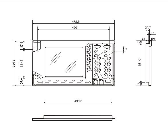
OPLINK 10.4” TFT OPERATOR PANEL
Side, front and upper view
Physical Characteristics
Width |
482.6 mm |
Height |
265.6 mm |
Depth |
39.7 mm (without cables) |
Weight |
3.5 Kg |
Mounting |
Rack 19" |
Protection |
IP54 |
1-2 |
10 Series Family - Installation Guide (14) |

Chapter 1
Mechanical Characteristics
BLINK 10.4” TFT OPERATOR PANEL
Side, front and upper view
Physical Characteristics
Width |
482.6 mm |
Height |
265.6 mm |
Depth |
39.7 mm (without cables) |
Weight |
3.3 Kg |
Mounting |
Rack 19" |
Protection |
IP54 |
10 Series Family Installation Guide (14) |
1-3 |
Chapter 1
Mechanical Characteristics
Drilling Template for OPLINK, BLINK operator panel
Ø7
1-4 |
10 Series Family - Installation Guide (14) |

Chapter 1
Mechanical Characteristics
KEYBOARD FOR OPLINK, BLINK OPERATOR PANEL AND THE CONTROL UNIT 10/110
Side and front view
Physical Characteristics
Width |
482.6 mm |
Height |
132.6 mm |
Depth |
20.5 mm (without cables) |
Weight |
1.3 Kg |
Mounting |
Rack 19" |
Drilling template for keyboard
10 Series Family Installation Guide (14) |
1-5 |
Chapter 1
Mechanical Characteristics
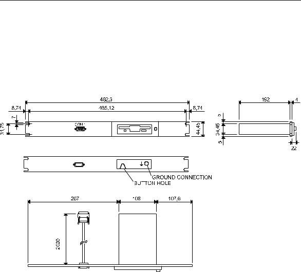
FDU KIT
Two FDU kits are available for mounting on the system: Standard and Reduced. The reduced FDU kit does not include either the FDU aluminium plate with related door and the COM1 serial interface extension cable.
Normal FDU Kit
Front, side and upper view of the Standard FDU kit
Physical characteristics
Width |
482.6 mm |
Height |
43.7 mm |
Depth |
218 mm (without cables) |
Weight |
1 kg |
Mounting |
19" rack |
Protection |
FDU front plate |
1-6 |
10 Series Family - Installation Guide (14) |
Chapter 1
Mechanical Characteristics
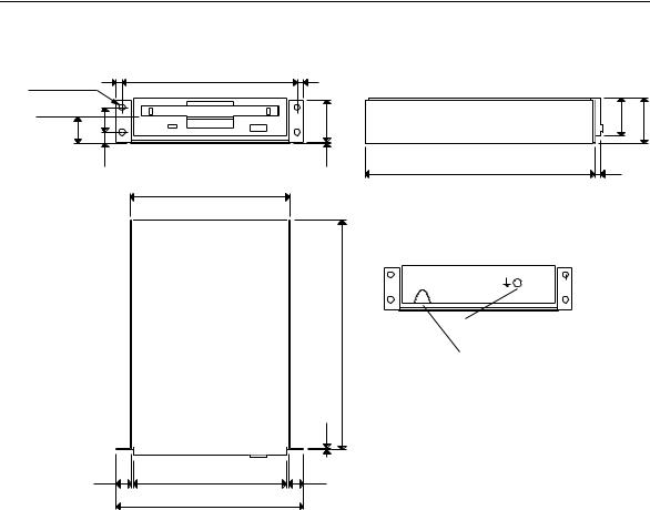
Reduced FDU Kit
4 Ø 4 HOLES 4 |
114 |
4 |
|
|
|
Floppy disk axis |
16 |
|
27,8 |
25,4 |
30,2 |
17 |
|
||||
7,5 |
1,2 |
151 |
4 |
|
|
104,6
192
1,2
9,9 |
101,6 |
9,9 |
|
122 |
|
GROUND CONNECTION
BUTTONHOLE
Front, side and upper view of the reduced FDU kit
Physical characteristics
Width |
122 |
mm |
Height |
30,2 mm |
|
Depth |
192 |
mm (without cables) |
Weight |
0,7 kg |
|
10 Series Family Installation Guide (14) |
1-7 |
Chapter 1
Mechanical Characteristics
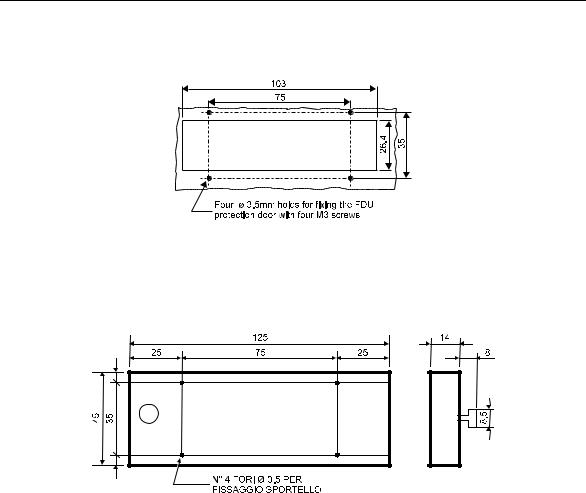
Drilling template for FDU access and fixing and the corresponding protection door
Dimensions of the protection door
1-8 |
10 Series Family - Installation Guide (14) |

Chapter 1
Mechanical Characteristics
10/110 CONTROL UNIT
Physical characteristics
Width |
482.6 mm |
Height |
265.6 mm |
Depth |
122 mm (without cables) |
Weight |
5,5 kg |
Mounting |
19" rack |
Protection |
IP54 (front only) |
Drilling Template for 10/110 Control Unit
10 Series Family Installation Guide (14) |
1-9 |
Chapter 1
Mechanical Characteristics
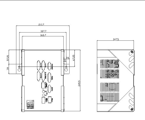
10/510S/I LIGHT CONTROL UNIT
10/510S/i Light System
1-10 |
10 Series Family - Installation Guide (14) |
Chapter 1
Mechanical Characteristics
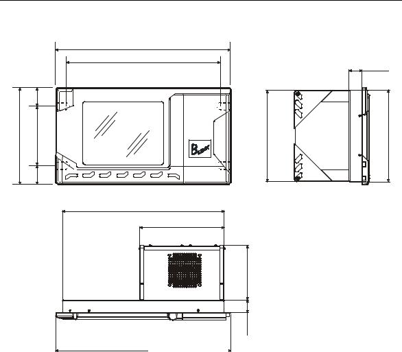
10/510i BLINK CONTROL UNIT
|
|
482,6 |
|
|
|
466 |
35,3 |
|
|
|
|
|
37,6 |
|
|
265,6 |
190,4 |
249,5 |
252 |
|
37,6 |
|
|
445
233
150
35,3 |
482,6 |
10/510i Blink System
Physical Characteristics
Width |
482.6 mm |
Height |
265.6 mm |
Depth |
290 mm (exit cables included) |
Weight |
6.4 Kg (boards included) |
Mounting |
in 19” rack |
Protection |
IP54 (only front) |
Voltage |
24Vdc (20÷30V) |
Current |
3A max (24Vdc) |
10 Series Family Installation Guide (14) |
1-11 |

Chapter 1
Mechanical Characteristics
10/510i OPLINK CONTROL UNIT
482,6
466
35,3
|
37,6 |
|
|
265,6 |
190,4 |
249,5 |
252 |
|
37,6 |
|
|
445
233
150
35,3 |
482,6 |
10/510i OpLink system
Physical Characteristics
Width |
482.6 mm |
Height |
265.6 mm |
Depth |
290 mm (exit cables included) |
Weight |
6.4 Kg (board included) |
Mounting |
in 19” rack |
Protection |
IP54 (only front) |
Voltage |
24Vdc (20÷30V) |
Current |
3A max (24Vdc) |
1-12 |
10 Series Family - Installation Guide (14) |
Chapter 1
Mechanical Characteristics
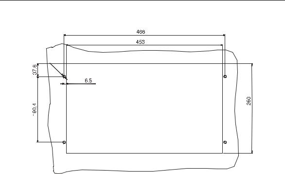
Drilling template for 10/510i Oplink/Blink Control Unit
Ø7
10 Series Family Installation Guide (14) |
1-13 |
Loading...