


10 Series CNC
PLUS
Application Manual
Code: 45006677Z
Rev. 11
PUBLICATION ISSUED BY:
OSAI S.p.A.
Via Torino, 14 - 10010 Barone Canavese (TO) – Italy
e-mail: sales@osai.it
Web: www.osai.it
Copyright 2002-2003 by OSAI
All rights reserved
Edition: July 2003
IMPORTANT USER INFORMATION
This document has been prepared in order to be used by OSAI. It describes the latest release of the
product.
OSAI reserves the right to modify and improve the product described by this document at any time
and without prior notice.
Actual application of this product is up to the user. In no event will OSAI be responsible or liable for
indirect or consequential damages that may result from installation or use of the equipment described
in this text.

abc

SUMMARY OF CHANGES
General
This publication has been issued with the software release 7.2.
This issue completely replaces the previous ones.
PAGE UPDATE TYPE
Chapter 3
Page 3 Updates values in SW02 system status flag tables.
Chapter 6
Page 2,3
Page 10,11
Page 13
Modified error codes in FB $EMERGNR
Modified error codes in $EMERGR
Added paragraph on FastWire emergency conditions
UPDATE
10 Series CNC PLUS Application Manual
Chapter 11
Chapter 12
Added new chapter on CANOPEN
Added new chapter on FASTWIRE
10 Series CNC PLUS Application Manual (11)

abc

Preface
10 Series CNC PLUS Application Manual
PREFACE
The 10 Series numerical control introduces many new Technical concepts. One of the most important
of these concepts is the concept of information exchange between the CNC and the integrated PLC
(Programmable Logic Controller).
Conventional controls use a window with a large amount of fixed flags, which are continuously
scanned and updated by both CNC and programmable logic control.
The concept of 10 Series by-passes this general conception with a simple but unique solution: both
CNC and PLC use function calls to alert each other, to pass information or to request a certain
action. These function calls need only be executed on event, thus freeing up CPU capacity and
increasing the general system performance.
This manual explains the new concept and shows how applications can use its power.
ABOUT THIS MANUAL
This manual is intended to be used by the OEM personnel in charge with the programming of the
machine tool interface. It gives an overview of the software architecture to be used to develop the
programmable logic.
• it does NOT explain the PLUS programming language and the use of any of its language
elements.
• it does NOT explain the use of the PLUSEDIT development software.
10 Series CNC PLUS Application Manual (10) 1

Preface
10 Series CNC PLUS Application Manual
This manual is structured as follows:
Chapter 1 explains the concepts of communication between the logic and the system.
Chapter 2 gives a detailed view of the structure of the routines running on the PLC module: it
shows the timing and the execution priorities of the different routines on the I/O
processor and it makes you familiar with the special execution mode of the
background logic programs. Finally, it gives a list of declarations needed to define
the different routines.
Chapter 3 deals with the data areas in the PLC module's memory and in its dual port.
Chapter 4 explains the routines which make up the interface between the part program and
the logic.
Chapter 5 shows how the executive command filters can be used.
Chapter 6 covers the emergency routines.
Chapter 7 explains the OEM softkey routine.
Chapter 8 is the practical part of the manual which explains how the controls communication
concept can be used to create powerful applications.
Chapter 9 this chapter describes how to use the INTERBUS feature on 10 Series systems.
Chapter 10 this chapter describes the configuration modality of PROFIBUS on 10 Series
systems.
Appendix A contains a glossary of verbs and expressions used in this manual.
OTHER MANUALS ABOUT PLUS
Beside this manual there are 2 other specific manuals about PLUS:
• 10 Series CNC PLUS LIBRARY code 4500 6682 C
This manual covers the library function calls and the function blocks available in the PLUS
programming language:
− Basic language function blocks
− Language extensions
− Counters and timers
− System function calls
− function calls
• 10 Series CNC PLUS LANGUAGE & PLUSEDIT code 4500 6672 P
This manual describes the PLUS language, the editors and the utilities to generate an executable
logic program:
− instruction list editor (IL) + basic language elements
− ladder diagram / function block diagram editor (FBD/LD)
− macro instruction list editor (MACRO-IL)
− sequential function chart editor (SFC)
− PLUSGEN generator (compiler)
− I/O configurator
− ASCII editor
2 10 Series CNC PLUS Application Manual (10)

Preface
CAUTION
IMPORTANT
10 Series CNC PLUS Application Manual
Other manuals may be of interest when programming a machine tool interface:
1. 10 Series CNC AMP - Software Characterisation Code : 4500 6667 V
describes the system/process software configuration utility and its parameters
2. 10 Series CNC Programming Manual Code: 4500 4457 K
describes the 10 Series CNC part program language
3. 10 Series CNC User Manual Code: 4500 4452 H
describes the use of the human interface, the CNC manual functions and the utilities available to
the operator
4. 10 Series Family Installation Guide Code 4500 6657 R
contains the complete information needed to realise a correct installation of the 10 Series CNC
system.
5. 10 Series CNC Software Installation Manual Code 4500 6687 N
contains the complete information needed to install the software release.
WARNINGS
For correct control operation, it is important to follow the information given in this manual. Take
particular care with topics bearing one of the mentions: WARNING, CAUTION or IMPORTANT, which
indicate the following types of information:
Draws attention to facts or circumstances that may cause damage to the control,
WARNING
to the machine or to operators.
Indicates information to be followed in order to avoid damage to equipment in
general.
Indicates information that must be followed carefully in order to ensure full
success of the application.
10 Series CNC PLUS Application Manual (10) 3

Preface
10 Series CNC PLUS Application Manual
END OF PREFACE
4 10 Series CNC PLUS Application Manual (10)

10 Series CNC PLUS Application Manual
INDEX
SYSTEM - APPLICATION LOGIC HANDSHAKE
LOGIC INTERFACE TASKS......................................................................................1-2
SYSTEM FUNCTION CALLS.....................................................................................1-2
COMMON DATA AREAS ..........................................................................................1-2
Index
ORGANIZATION OF THE APPLICATION LOGIC
AVAILABLE ROUTINES ...........................................................................................2-1
Routines activated on event (fast input routines).................................................2-1
Routines activated on clock (foreground) ............................................................2-1
Routines activated on emergency (emergency routine) ........................................2-2
Routines activated on softkey - (OEM softkey routine) ........................................2-2
Routines activated background routines.............................................................2-2
Routines activated on part program events (part program interface).......................2-2
Routines activated on system commands (consent request)................................2-2
TASK SYNCHRONIZATION.......................................................................................2-5
BACKGROUND EXECUTION.....................................................................................2-9
PLUS ROUTINES DECLARATION .............................................................................2-12
I/O PROCESSOR /SYSTEM DATA AREAS
SYSTEM STATUS FLAGS ........................................................................................3-2
PROCESS STATUS FLAGS .....................................................................................3-6
USER DEFINED / GLOBAL VARIABLES (G VARIABLES)...........................................3-15
M VARIABLES.........................................................................................................3-16
TABLES ..................................................................................................................3-17
Axes Table .....................................................................................................3-17
Tool table........................................................................................................3-21
Tool offset table ...............................................................................................3-23
User table .......................................................................................................3-27
PART PROGRAM INTERFACE
STRUCTURE............................................................................................................4-1
PART PROGRAM INTERFACE TASK........................................................................4-2
10 Series CNC PLUS Application Manual (11) i

Index
10 Series CNC PLUS Application Manual
PART PROGRAM INTERFACE ROUTINES ................................................................4-6
COORDINATED AXES..............................................................................................4-8
Consent to move routine...................................................................................4-8
Motion blocks .................................................................................................4-10
Consent to move management ..........................................................................4-11
End of motion routine .......................................................................................4-12
End of move management ................................................................................4-13
M FUNCTIONS .........................................................................................................4-14
M decode routine.............................................................................................4-15
M code management (EXPEDITE).....................................................................4-18
AMP set up for M functions ..............................................................................4-19
PSEUDO AXES........................................................................................................4-25
Pseudo axes routine ........................................................................................4-25
S WORD..................................................................................................................4-29
S decode routine.............................................................................................4-29
T WORD ..................................................................................................................4-34
T decode routine..............................................................................................4-37
END OF BLOCK ROUTINE........................................................................................4-43
TOOL OFFSET PRESETTING ...................................................................................4-45
TOOL OFFSET REQUALIFICATION ..........................................................................4-48
DECLARE TOOL LIFE EXPIRED...............................................................................4-51
PROBING CYCLE COMPLETED................................................................................4-53
EXECUTIVE COMMAND FILTER ROUTINES
CYCLE START PUSH BUTTON (PRESSED) ..............................................................5-5
CYCLE START PUSH BUTTON (RELEASED).............................................................5-6
CONTROL RESET....................................................................................................5-7
MODE SELECT........................................................................................................5-8
AXIS SELECT ..........................................................................................................5-9
MANUAL FEEDRATE OVERRIDE SELECTOR ............................................................5-10
FEEDRATE OVERRIDE SELECTOR...........................................................................5-11
SPINDLE SPEED OVERRIDE SELECTOR..................................................................5-12
RAPID FEEDRATE OVERRIDE SELECTOR................................................................5-13
INTERPOLATOR STOP (HOLD) REQUESTED ...........................................................5-14
RE-START INTERPOLATOR (EXIT FROM HOLD)......................................................5-15
EMERGENCY MANAGEMENT
UNRECOVERABLE EMERGENCIES ..........................................................................6-2
DSI Emergencies ............................................................................................6-5
RECOVERABLE EMERGENCIES...............................................................................6-10
DSI Emergencies ............................................................................................6-12
FASTWIRE EMERGENCY CONDITIONS ..........................................................6-13
OEM SOFTKEYS
INTERFACE ROUTINE ..............................................................................................7-1
ON/OFF Softkeys............................................................................................7-3
MAINTAINED Softkey ......................................................................................7-3
DATA ENTRY Softkeys....................................................................................7-4
10 Series CNC PLUS Application Manual (11)ii

10 Series CNC PLUS Application Manual
NORMAL Softkeys..........................................................................................7-5
OPLink Function Keys .....................................................................................7-5
STANDARD APPLICATION NOTES
PLUS INITIALIZATION.............................................................................................8-1
MACHINE TOOL POWER UP AND RE-POWER UP AFTER E-STOP ...........................8-2
HOLD MANAGEMENT..............................................................................................8-3
RESET MANAGEMENT.............................................................................................8-6
SPINDLE MANAGEMENT.........................................................................................8-9
CO-ORDINATED AXES MOVES (MAS) FROM PLUS ..................................................8-11
HARDWARE OVER TRAVEL LIMIT SWITCHES .........................................................8-16
AXES HOMING........................................................................................................8-19
PLUS MESSAGES DISPLAY....................................................................................8-22
FEED HOLD .............................................................................................................8-25
ACTIVE RESET........................................................................................................8-27
MANUAL JOG BY THE LOGIC..................................................................................8-33
FEED RATE OVERRIDE CONTROL...........................................................................8-34
FEED RATE BYPASS...............................................................................................8-37
SERIAL LINE MANAGEMENT (RS-232) .....................................................................8-39
AXIS POSTIONING VIA RS-232 SERIAL LINE...........................................................8-41
Configuration...................................................................................................8-41
Programming ..................................................................................................8-42
Installation Specifications.................................................................................8-45
Index
INTERBUS® FEATURES ON 10 SERIES SYSTEMS
CONFIGURATION APPLICATION IBS CMD..............................................................9-3
On-line Operations ...........................................................................................9-5
Off-line Operations...........................................................................................9-13
TRANSFERRING THE CONFIGURATION FILE TO THE 10 SERIES CNC .....................9-15
INTERBUS ERRORS ................................................................................................9-16
SLAVE PROFIBUS® FUNCTIONALITIES ON 10 SERIES
SYSTEMS
SLAVE PROFIBUS CONFIGURATION.......................................................................10-2
DESCRIPTION OF ERROR CODES RETURNED DURING THE FUNCTIONING OF
THE SLAVE PROFIBUS. ..........................................................................................10-4
CANOPEN® FUNCTIONS ON SERIES 10 SYSTEMS
CANOPEN BUS CONFIGURATION............................................................................11-2
CONFIGURATION EXAMPLE....................................................................................11-4
DESCRIPTION OF ERROR CODES RETURNED DURING OPERATION OF
CANOPEN BUS ........................................................................................................11-5
Errors from RIO EC modules ............................................................................11-5
Errors from CWIO modules ...............................................................................11-7
ERRORS RETURNED DURING CNC POWER UP .......................................................11-7
10 Series CNC PLUS Application Manual (11) iii

Index
10 Series CNC PLUS Application Manual
FASTWIRE® FUNCTIONS ON SERIES 10 SYSTEMS
FASTWIRE BUS CONFIGURATION ..........................................................................12-2
CONFIGURATION EXAMPLE....................................................................................12-4
DESCRIPTION OF ERROR CODES RETURNED DURING OPERATION OF
FASTWIRE BUS ......................................................................................................12-5
ERRORS RETURNED DURING CNC POWER UP .......................................................12-6
GLOSSARY
GLOSSARY.............................................................................................................A-1
END INDEX
10 Series CNC PLUS Application Manual (11)iv
1
SYSTEM - APPLICATION LOGIC HANDSHAKE
Chapter
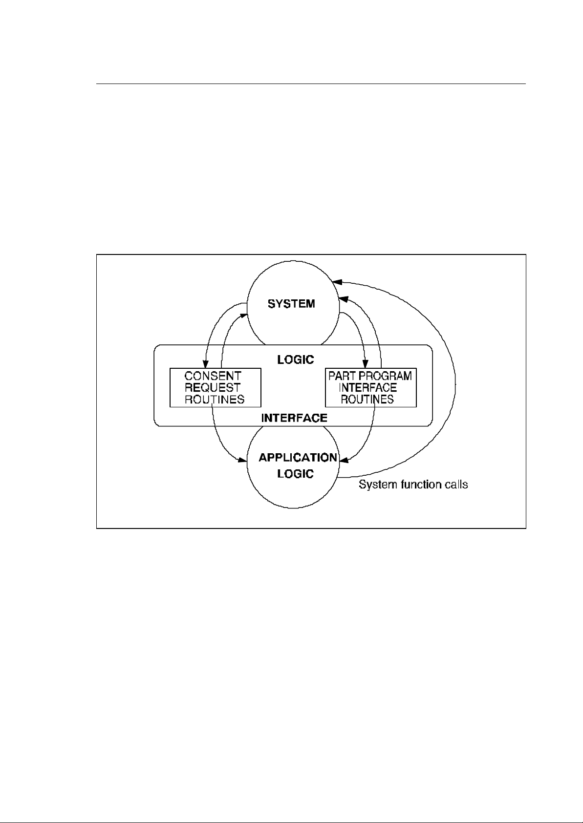
Fig. 1-1 System - Application Logic Handshake
10 Series CNC PLUS Application Manual (02) 1-1

Chapter 1
System - Application Logic Handshake
LOGIC INTERFACE TASKS
The system communicates to the logic through the logic interface. This Interface consists of two
tasks, the "consent request task " and the "part program interface " task. These tasks receive the
commands and the parameters from the system, process them and sends some of them to the
application logic program.
Each one of these tasks can be made up of several routines which have to be written by the PLUS
programmer. Some of the routines are optional, i.e. if they have not been written, they will not be
activated by the system.
SYSTEM FUNCTION CALLS
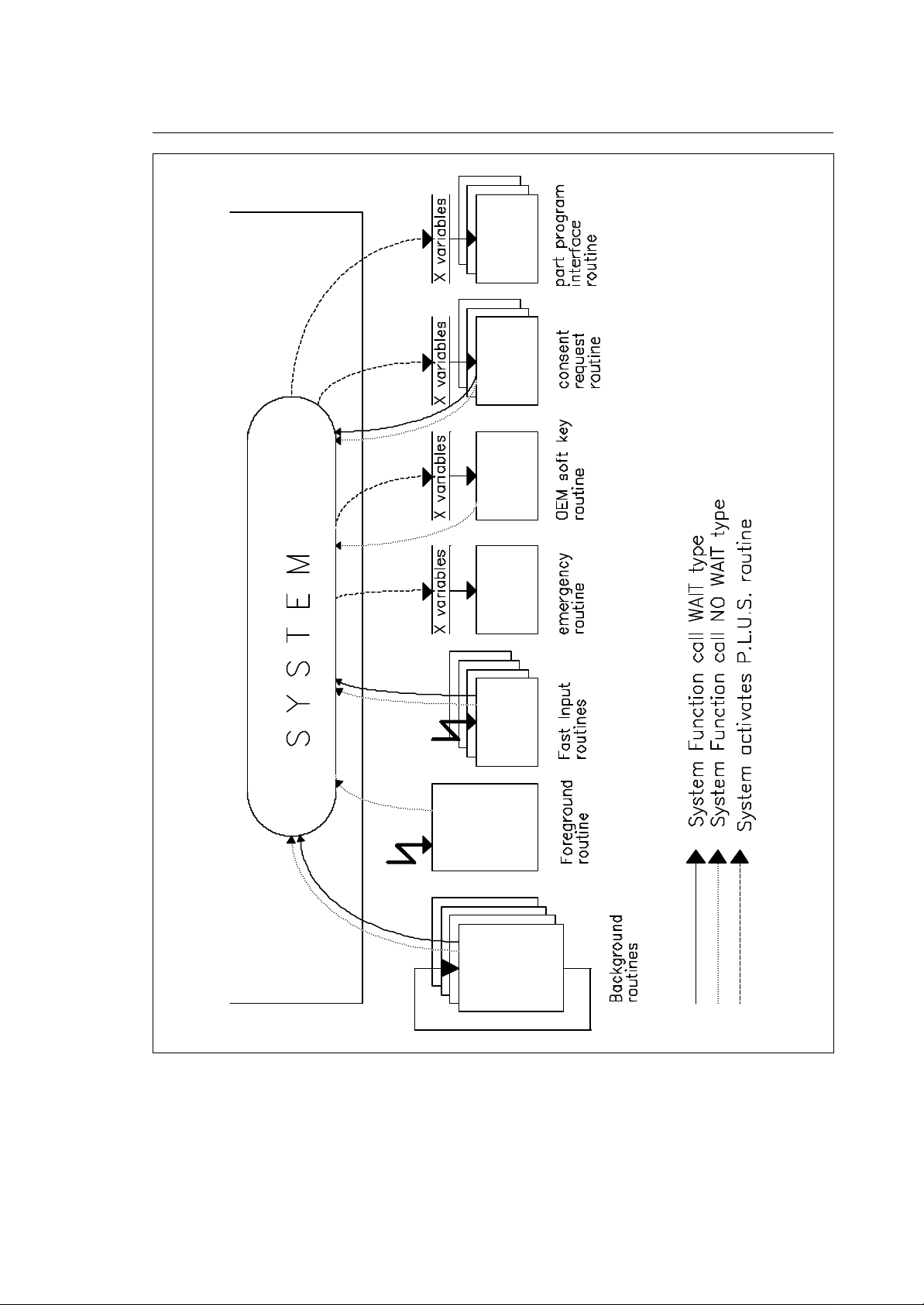
The logic from its part communicates with the system through a set of function calls which can
include a parameter exchange between the two parties. There are two types of function calls:
• NO WAIT functions pass a command (with parameters) to the system without waiting for an
answer (the application program execution is not suspended).
• WAIT functions pass a command to the system and wait for a res ponse ( the logic execution is
suspended until the response arrives)
COMMON DATA AREAS
The third communication channel between the logic and the system are the common data areas in
the battery buffered dual ported memory of the I/O processor board. These areas can be divided in:
• System area. This is a group of 100 variables of the type short (16 bit integer word) containing the
status of the system and/or the processes.
• Global variables. These variables are referred to as "G" variables. They have two formats; short
and double (precision floating point). They can be read and written by both part program and logic
program. The G variables are retentive, i.e. they are not cleared after powering up the system.
• Tables. Tables are retentive memory areas in the dual port of the I/O processor module. They can
be commonly accessed by the system and by the logic programs. The data contained in tables
includes:
− tool data
− tool offset data
− axes origin data
− axes offsets
END OF CHAPTER
1-2 10 Series CNC PLUS Application Manual (02)

Chapter
2
ORGANIZATION OF THE APPLICATION LOGIC
The logic program is organised in independent routines. All these routines run on the I/O processor
module and have different priorities depending on their use. The program's various routines are
activated by the PLC's Operating System either following specific events or on clock or they are
continuously executed (in loop).
AVAILABLE ROUTINES
Routines activated on event (fast input routines)
You can define up to 4 interrupt routines (one for each input) which are executed when the relevant
"fast input" on the I/O processor module is set true. Each routine is dedicated to a specific fast input.
The association of fast input and corresponding routine is given by the predefined names for the
routines. The execution starts on the true-going edge of the corresponding fast input signal. All other
activities of the I/O processor task will be suspended for the duration of the execution of the routines.
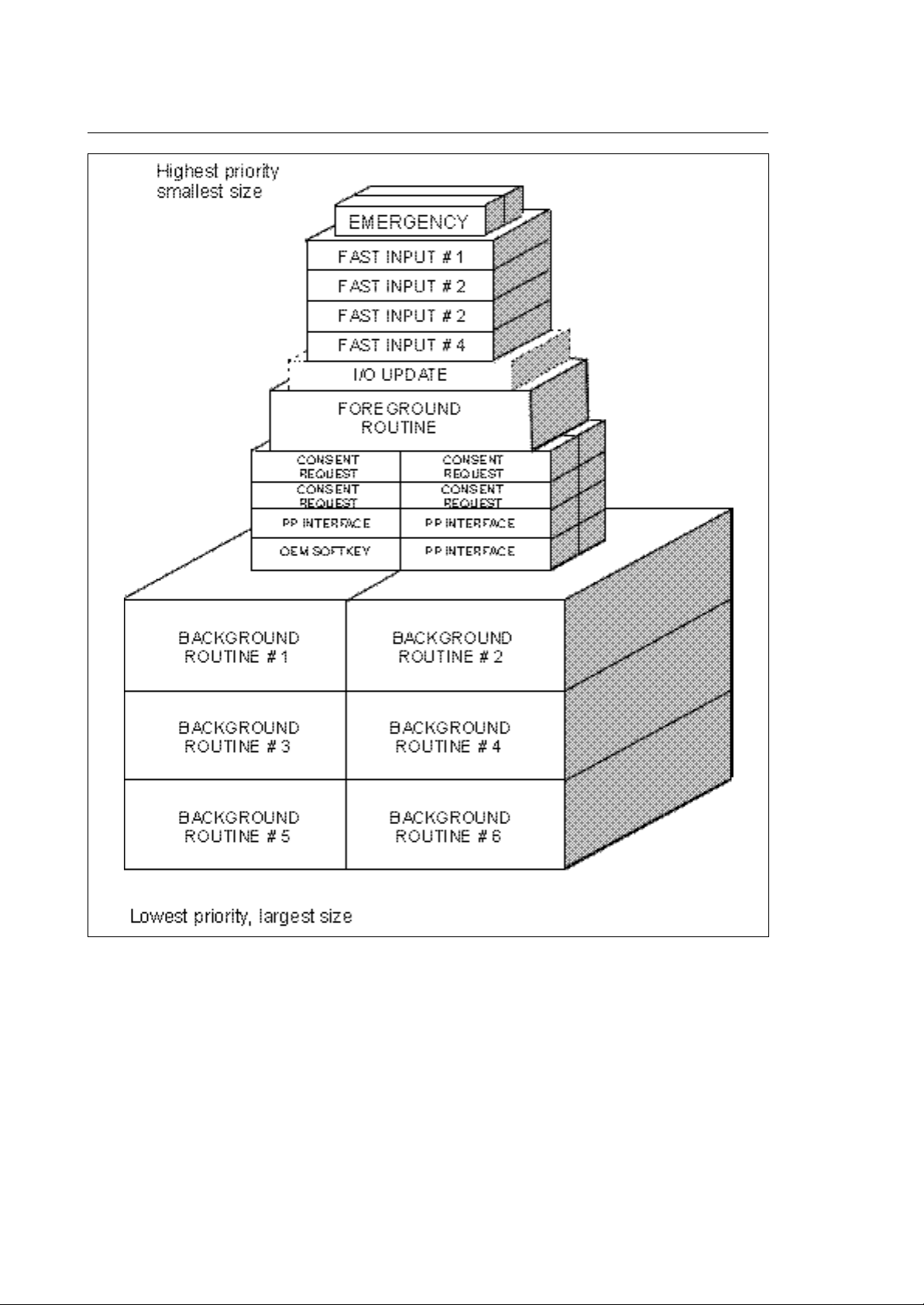
In other words, the fast input routines have the highest execution priority of all routines. For this
reason these routines must be as short as possible (<< 5ms).
Routines activated on clock (foreground)
This routine (only one can be present) will be executed on each clock tick of the I/O processor
module. This clock tick is presently set to 10 ms. If the foreground routine execution time exceeds
the available time (max. 10 ms), the system will generate an "overrun error" and go in emergency
status.
The primary use of the foreground routine is to "latch" events to be executed with precise and fast
timing such as read/write physical I/O device status or handling of security/emergency devices.
10 Series CNC PLUS Application Manual (08) 2-1

Chapter 2
Organization of the Application Logic
Routines activated on emergency (emergency routine)
Two emergency routines are available: their task is to handle the anomalies (emergencies) detected
by the system. The anomaly detected can be recoverable or not recoverable. On emergency, the
logic may have to execute sequences of logic in parallel to the steps taken by the system.
Routines activated on softkey - (OEM softkey routine)
There is one routine related to the OEM configured softkeys. Every time an OEM softkey is pressed
(or released), this routine will be executed and the softkey's parameters will be passed to it.
The OEM softkeys are defined in AMP, allowing OEM to provide its application with the identical look
and feel as the standard system operations (refer to AMP configuration manual). The OEM softkey
routine runs at a very low priority.
Routines activated background routines
A background routine is continuously executed in a loop like a program in a standard PLC. The I/O
processor can run up to 12 background routines in parallel.
Each background routine can execute functions of the WAIT type which will suspend the execution of
that background routine until arrival of the response. In the mean time the other background routines
will continue executing. In reality, when one routine is suspended, control will be passed to the next
one.
The logic programmer has to optimise the performance of the I/O processor using an optimised
distribution of the logic in the available background routines.
Routines activated on part program events (part program interface)
These routines (one for each configured process) will run every time, a part program block contains
information related to the logic (like M code, S word and Tool information and all other functions that
can be grouped under the definition of logic auxiliary functions).
Routines activated on system commands (consent request)
These routines (one for each configured process) run every time, a command is given to the system
(like cycle start, reset, etc.), allowing the logic to read and/or to inhibit the commands given to the
system by the operator.
This routine covers most commands given to the system from softkey and/or MTB panel.
2-2 10 Series CNC PLUS Application Manual (08)
Chapter 2
Organization of the Application Logic
Fig. 2-1 Logic organisation and communication channels
10 Series CNC PLUS Application Manual (08) 2-3
Chapter 2
Organization of the Application Logic
SYSTEM CPU
PART
PROGRAM
INTERFACE
BACKGROUND
ROUTINE
# 1
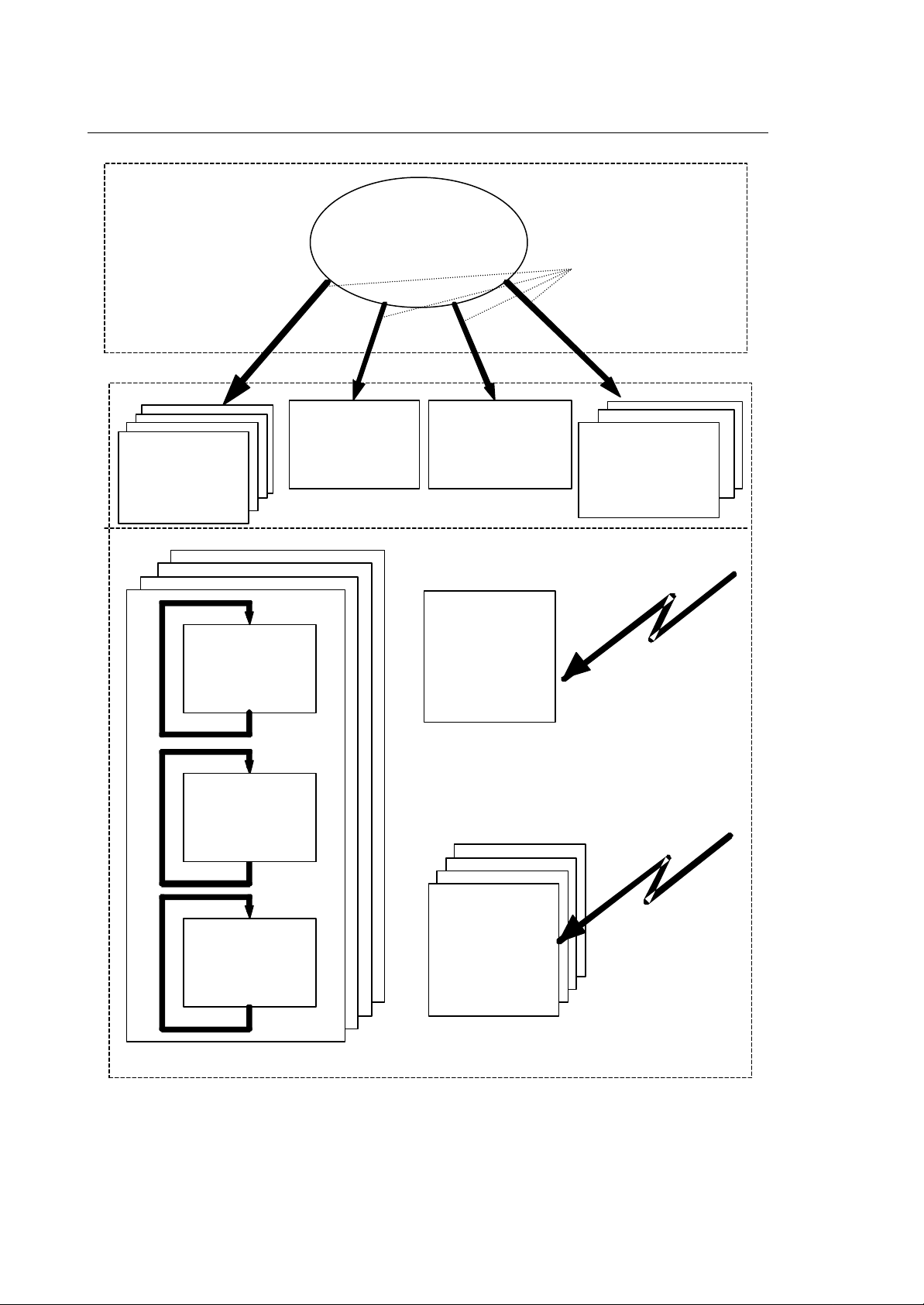
SYSTEM
EMERGENCY
ROUTINE
LOGIC INTERFACE
OEM SOFTKEY
ROUTINE
FOREGROUND
ROUTINE
REQUEST TO
EXECUTE LOGIC
ROUTINES
CONSENT
REQUEST
ROUTINE
10 MS
TIMED
INTERRUPT
BACKGROUND
ROUTINE
# 2
BACKGROUND
ROUTINE
# 3
FAST INPUT
ROUTINES
I/O PROCESSOR MODULE
Fig. 2-2 Routine scheduling
FAST INPUT
HARDWARE
INTERRUPT
2-4 10 Series CNC PLUS Application Manual (08)
Chapter 2
Organization of the Application Logic
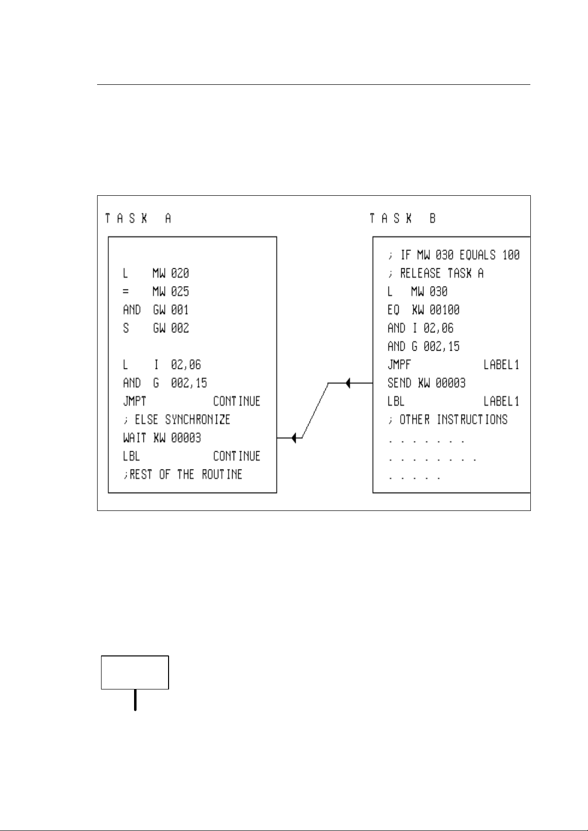
TASK SYNCHRONIZATION
You can synchronize some of the different previously discussed routines with a set of semaphores
(32) together with the instructions WAIT and SEND. With the WAIT instruction and one of the
semaphore numbers (0-31) you can suspend the execution of a routine (task) until one of the other
routines uses the SEND instruction with the same semaphore number. In this way you can
synchronize the execution of one task with an event in another task.
Fig. 2-3 Task Synchronization
The WAIT (3) instruction suspends the execution of task A until the SEND (3) command in task B is
executed on the same semaphore. Of course the exact point in time of the task's resumption also
depends on its priority.
NOTE:
A SEND on a semaphore can be issued without a task waiting for this semaphore. The SEND
instruction will simply be ignored. Any routine in WAIT status can only be released by the relative
SEND instruction. The routine that holds the SEND instruction must be synchronized with the routine
holding the WAIT status request.
You are not allowed to use the WAIT/DLY instructions in foreground, fast input
IMPORTANT
10 Series CNC PLUS Application Manual (08) 2-5
and emergency routines
Chapter 2
Organization of the Application Logic
Fig. 2-4 Routine priority and size
2-6 10 Series CNC PLUS Application Manual (08)
Chapter 2
Organization of the Application Logic
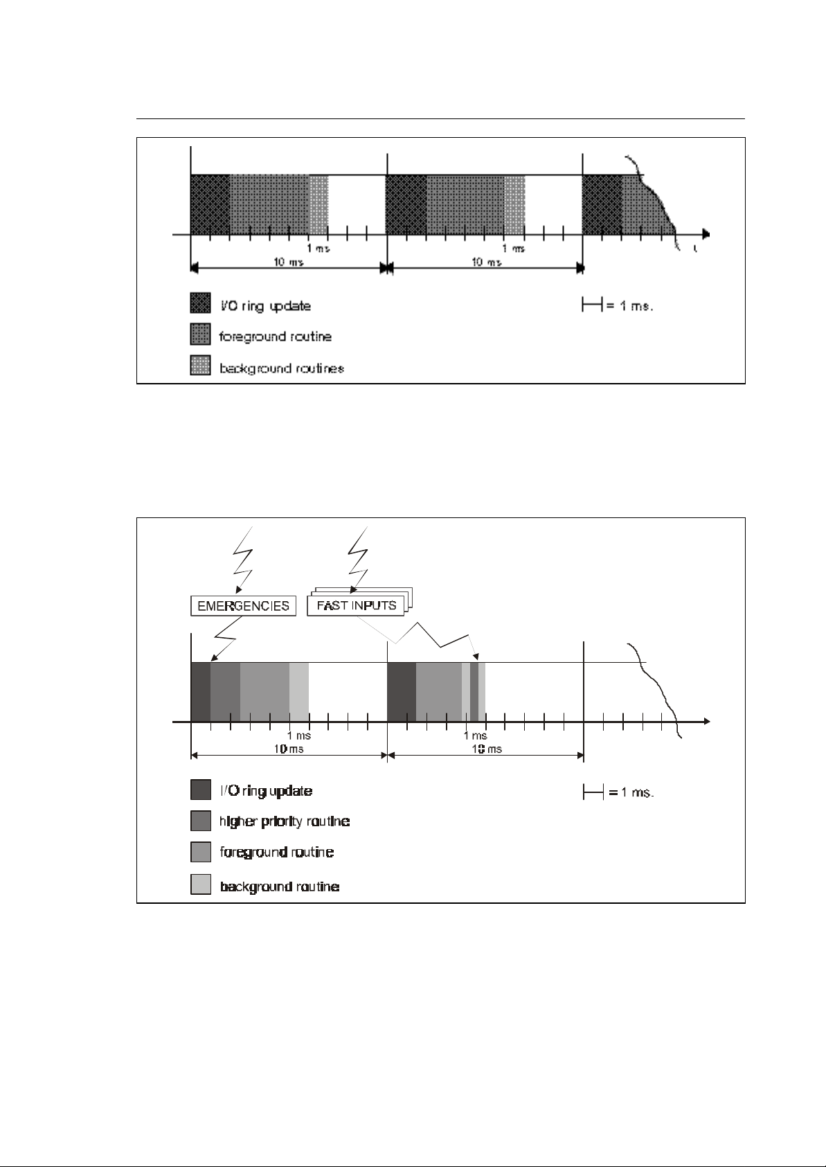
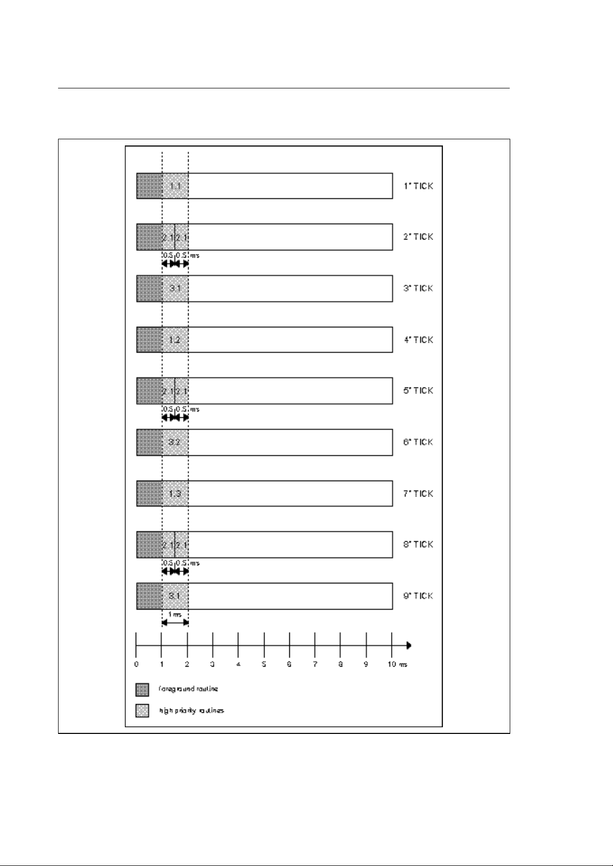
Fig. 2-5 Steady Operation
Every 10 ms the system updates the I/O's, executes the all foreground routines and executes one of
the background ones for 1 ms. Every 10 ms one of the background routines present will be executed
in sequence. If a background routine takes less than 1 ms, it will be rerun from the start, until this
time runs out. No routine will be interrupted.
Fig. 2-6 High Priority Interrupt Operation
10 Series CNC PLUS Application Manual (08) 2-7
Chapter 2
Organization of the Application Logic
When emergencies occur or fast input routines have to be processed, the steady operation of the I/O
processor will be interrupted and the high priority routines required will be executed immediately. Note
that the steady execution may be interrupted anywhere during the execution of the I/O ring update, of
the foreground logic or of the background logic.
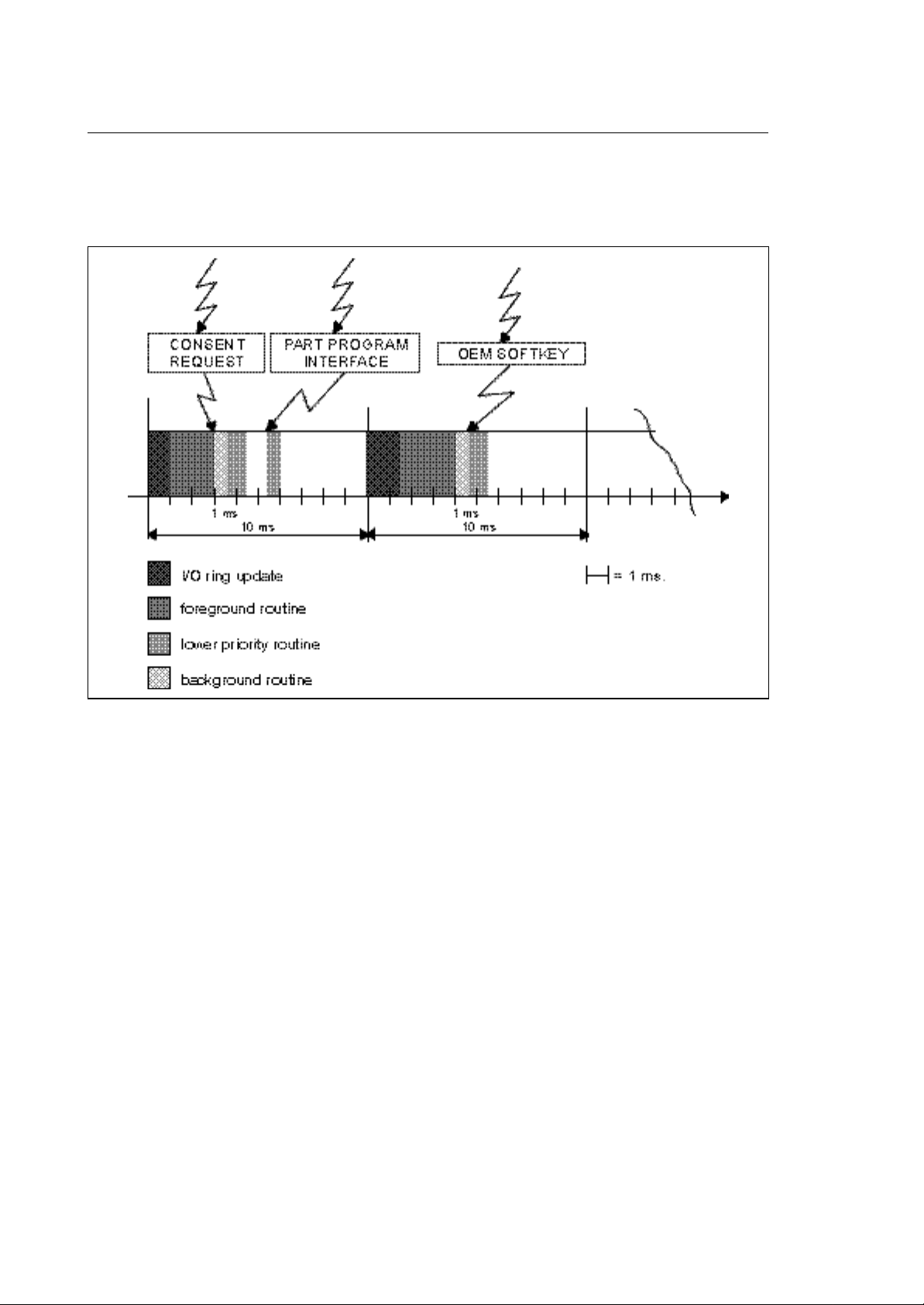
Fig. 2-7 Low Priority Interrupt Operation
When low priority events occur, like consent request calls, part program Interface calls or even OEM
softkey calls, the foreground routine and all other higher priority tasks will not be interrupted. These
low priority routines will only run during the time available for background logic execution.
2-8 10 Series CNC PLUS Application Manual (08)
Chapter 2
Organization of the Application Logic
BACKGROUND EXECUTION
There can be up to 12 background routines. The background routines are those with the lowest
priorities among the routines making up the logic application and are executed in turn every 10 ms
(Tick Plus) for 1 ms.
At each Tick Plus the integrated PLC updates the I/O's and the foreground routines.
Consensus routines, part program interfaces and OEM softkeys are enabled at system request and
interrupt background execution.
After enabling all high priority routines at each Tick Plus, the system enables one of the background
routines and lets it run for 1 ms.
At each Tick Plus the system enables a different background routine. The sequence of activation is
determined by the number associated with the routine name. At the first Tick Plus the background
routine 1 ($BACK1) is enabled, at the second the background routine 2 ($BACK2) and so on.
Once the last background routine has been enabled, the system again starts with the first.
Therefore an individual background routine is executed over several Tick Plus, alternating part of its
code with that of other background routines in time slicing. If a background routine suspends its
execution voluntarily by calling a function such as WAIT or DELAY or indirectly by calling system
functions of the WAIT type, the remaining time up to the end of the millisecond is free for other
system operations (processing a part program, displaying, etc).
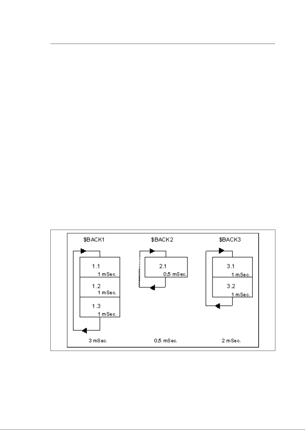
If a background routines is shorter than 1 ms, this is executed several times during the Tick Plus. If
the background task to be enabled is suspended at a new Tick Plus, no other background routine is
executed and the millisecond reserved for it is used by the system.
Fig. 2-8 Background logic execution
Fig. 2.8 shows 3 background loops with total execution times of 3, of 0.5 and 2 ms respectively.
10 Series CNC PLUS Application Manual (08) 2-9
Chapter 2
Organization of the Application Logic
Supposing after foreground execution + I/O ring management the remaining time for each sampling is
constant at 5 mSec, the above routine are executed in the following sequence:
Fig. 2-9 Background execution sequence
2-10 10 Series CNC PLUS Application Manual (08)

Chapter 2
Organization of the Application Logic
As can be seen, at each cycle a different background routine is started, which means that a short
background routine is executed more often than a long one.
Referring to the example, the repeat frequency of the 3 loops will be:
$BACK 1 90 ms
$BACK 2 30 ms
$BACK 3 60 ms
The formula for calculating the frequency of a background routine is:
duration of the background routine x number of background routines x 10
IMPORTANT
In this example it is assumed, that there are no interrupts (fast inputs, OEM
softkey, requests form a part program or from the operator)
10 Series CNC PLUS Application Manual (08) 2-11

Chapter 2
Organization of the Application Logic
PLUS ROUTINES DECLARATION
To make all the routines described before available to be used, they must be declared in the source
program for the logic.
FOREGROUND routine ( 10 ms execution)
DTSK $FORE
foreground routine body
ETSK
BACKGROUND routines (loop execution)
DTSK $BACK1
background routine body
ETSK
and so on, up to
DTSK $BACK12
background routine body
ETSK
FAST INPUT routines (on event execution)
DTSK $FIN1
fast input #1 routine body
ETSK
DTSK $FIN2
fast input #2 routine body
ETSK
DTSK $FIN3
fast input #3 routine body
ETSK
DTSK $FIN4
fast input #4 routine body
ETSK
EMERGENCY routines (on event execution)
DTSK $EMERGR recoverable emergency
emergency routine body
ETSK
DTSK $EMERGNR unrecoverable emergency
emergency routine body
ETSK
2-12 10 Series CNC PLUS Application Manual (08)

OEM SOFTKEY INTERFACE routine
DTSK $OEMSFTK
OEM Softkey interface routine body
ETSK
PART PROGRAM INTERFACE routines (on part program events)
DTSK $nCONMOV
body of consent to move routine
ETSK
DTSK $nENDMOV
body of end of motion routine
ETSK
DTSK $nMDECOD
body of M function decode routine
ETSK
Chapter 2
Organization of the Application Logic
DTSK $nPSEUDO
body of pseudo axes decode routine
ETSK
DTSK $nSPROG
body of S word decode routine
ETSK
DTSK $nTPROG
body of T word decode routine
ETSK
DTSK $nEOB
body of End Of Block routine
ETSK
DTSK $nRQP
body of tool dimension offset interface
ETSK
DTSK $nRQT
body of tool wear offset interface routine
ETSK
DTSK $nTOU
body of tool life interface routine
ETSK
DTSK $nQUTAST
body of interface routine for measuring cycles
ETSK
10 Series CNC PLUS Application Manual (08) 2-13

Chapter 2
Organization of the Application Logic
CONSENT REQUEST routines (on softkey or MTB panel)
DTSK $n_CYCLE
cycle start pushed
ETSK
DTSK $n_CYOFF
cycle start released
ETSK
DTSK $n_HOLDON
Request to enter HOLD status
ETSK
DTSK $n_HOLDOF
Request to exit from HOLD status
ETSK
DTSK $n_RESET
reset button pushed
ETSK
DTSK $n_SETMOD
mode selected
ETSK
DTSK $n_PUTFMA
manual feedrate selected
ETSK
DTSK $n_PUTFED
feedrate override value selected
ETSK
DTSK $n_PUTRAP
rapid feedrate override value
ETSK
DTSK $n_PUTSPE
spindle speed override value selected
ETSK
DTSK $n_SELAXI
axis selected for manual motion
ETSK
NOTE:
"n" indicates the process number (a number in the range 1...20)
END OF CHAPTER
2-14 10 Series CNC PLUS Application Manual (08)
Chapter
3
I/O PROCESSOR /SYSTEM DATA AREAS
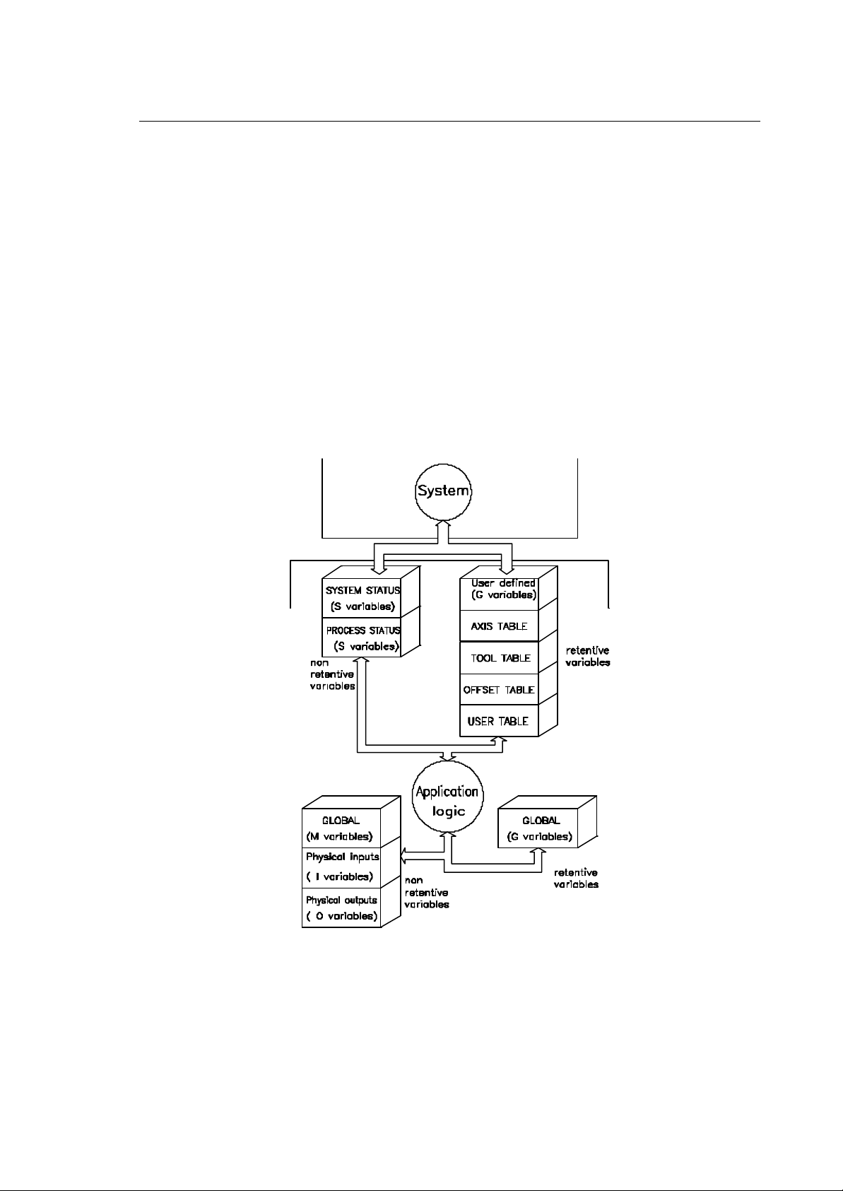
The I/O processor and the system share a data area in the dual ported memory of the I/O processor
module. This data area contains an I/O image, global retentive variables (G), system status variables
and 4 retentive tables with machine tool related data. Fig. 3-1 gives a detailed overview of all data
areas on the I/O processor, which are available to the application logic.
Fig. 3-1 Memory areas available to PLUS
10 Series CNC PLUS Application Manual (11) 3-1
Chapter 3
I/O Processor /System Data Areas
SYSTEM STATUS FLAGS
There are 500 system variables. They all have the short format. The first 20 variables (SW 00-SW 19)
are used to exchange some general system information between the logic program and the system.
Since the purpose of these variables is predefined, they have predefined symbolic names. Most of the
variables are read only to the logic (R/O). Only SW 03, SW 04 and SW 12 can be written and read by
the logic (R/W). SW Variables can be managed as words (I) or as single bits (B) or both (B/I).:
WORD MNEMONIC TITLE ACCESS PROT
SW 00 RESERVED FOR FUTURE USE
SW 01 S_SECURLEV ACTIVE SECURITY LEVEL I R/O
SW 02 S_CNINFO NC STATE INFORMATION B R/O
SW 03 S_HLS1 HOME LIMIT SWITCHES 1 B/I R/W
SW 04 S_HLS2 HOME LIMIT SWITCHES 2 B/I R/W
SW 05 RESERVED FOR FUTURE USE
SW 06 RESERVED FOR FUTURE USE
SW 07 RESERVED FOR FUTURE USE
SW 08 RESERVED FOR FUTURE USE
SW 09 S_PROCSEL SELECTED PROCESS I R/O
SW 10 S_SCRNSEL SELECTED SCREEN I R/O
SW 11 S_UNITS CONFIGURED UNITS B R/O
SW 12 RESERVED FOR FUTURE USE
SW 13 RESERVED FOR FUTURE USE
SW 14 RESERVED FOR FUTURE USE
SW 15 RESERVED FOR FUTURE USE
SW 16 S_NOWAIT NO WAIT CALL COUNTER I R/O
SW 17 S_CNCTYPE CONTROL TYPE B/I R/O
SW 18 RESERVED FOR FUTURE USE
SW 19 RESERVED FOR FUTURE USE
Hereafter, all variables and their functions will be discussed in more detail.
R/W SYSTEM VARIABLE SW 01 S_SECURLEV
WORD Title: Home Limit switches
SW 01 S_SECURLEV actually active security level value in the range of 0-6
(see SECURITY chapter in User Manual)
3-2 10 Series CNC PLUS Application Manual (11)

I/O Processor /System Data Areas
R/O SYSTEM VARIABLE SW 02 S_CNINFO
BIT Title: NC state information
Chapter 3
S 02,00
S 02,01
S 02,02
S 02,03
up to
S 02,15
R/W SYSTEM VARIABLE SW 03 S_HLS1
BIT Title: Home limit switches
S 03,00
S 03,01
through
S 03,15
S_OVRT.00
S_AXES
S_TUNING
reserved
S_HLS1.00 Home limit switch axis with ID 1
S_HLS1.01 Home limit switch axis with ID 2
S_HLS1.15 Home limit switch axis with ID 16
The system temperature has reached 45° C.
If the temperature goes higher, the controller switches off (50° C)
This signal is only valid for systems equipped with temperature
sensors
This indicates that the axes boards are ready to receive commands
from the logic
Flag correlated to FastWire. Shows that the CNC has shifted to
TUNING modality for setup of OS3 drives.
R/W SYSTEM VARIABLE SW 04 S_HLS2
BIT Title: Home limit switches
S 04,00
S 04,01
through
S 04,15
S_HLS2.00 Home limit switch axis with ID 17
S_HLS2.01 Home limit switch axis with ID 18
S_HLS2.15 Home limit switch axis with ID 32
Home limit switches are wired as NC contacts: The input goes to a low level when the machine hits
the switch.
R/O SYSTEM VARIABLE SW 09 S_PROCSEL
WORD Title: Actually selected process for operation
SW 09 S_PROCSEL This flag contains the number of the actually selected
process. It is an integer in the range from 1 to 20.
10 Series CNC PLUS Application Manual (11) 3-3

Chapter 3
I/O Processor /System Data Areas
R/O SYSTEM VARIABLE SW 10 S_SCRNSEL
WORD Title: Actually selected screen number
SW 10 S_SCRNSEL This flag contains the number of the screen actually
selected. It is a positive integer number (AMP - SW
Characterisation Manual)
The S_SCRNSEL variable contains the number corresponding to the selected screen as configured in
AMP. The variable can have the following values:
SCREEN NAME SCREEN NUMBER
Process main screen
Logic main screen
Large axes position
Logic screen 1 (full)
Logic screen 2 (full)
Logic screen 3 (full)
Logic screen 4 (full)
Additional screen 1
Additional screen 2
Additional screen 3
Additional screen 4
Additional screen 5
R/O SYSTEM VARIABLE SW 11 S_UNITS
BIT Title: Configured units (metric/inch)
S 11,00
S 11,01
through
S 11,15
S_UNITS.00 METRIC = 1 , INCH = 0
reserved spares
1
2
3
4
5
6
7
8
9
10
11
12
3-4 10 Series CNC PLUS Application Manual (11)

R/O PROCESS VARIABLE SW 16 S_NOWAIT
WORD Title: NO WAIT call counter
SW 16 S_NOWAIT This word contains the number of NOWAIT calls placed. It is valid
only for 10/365 and 10/385 systems.
R/O PROCESS VARIABLE SW 17 S_CNCTYPE
WORD Title: Controller type
SW 17 S_CNCTYPE This word is used for indicating the control type.
The lower byte of SW17 is used for indicating the CNC model:
Value = 0 10/110 NC
Chapter 3
I/O Processor /System Data Areas
IMPORTANT
Value = 1 10/510 NC
Value = 4 10/565 NC
Value = 5 10/100 NC
Value = 8 10/585 NC
Value = 255 10/3xx NC
The higher byte of SW17 is reserved for future developments.
10 Series CNC PLUS Application Manual (11) 3-5

Chapter 3
CAUTION
I/O Processor /System Data Areas
PROCESS STATUS FLAGS
All words in the process flag window have mnemonic names which start with the process number
(S_1 through S_20 prefixes for the processes 1 through 20). For each process there is one group of
20 words. Each group is identically struc tured.
The access to process variables is as discussed for the system variables.
For every process there will be a group of flags as for process number 1. The functionality is identical,
the mnemonics only differ by the number of the process. The symbolic addresses SW nn must be
incremented by 20 for each further process.
These flags are dynamically updated. They are not synchronized with the
execution of the logic (except S_nRESE and S_nHOLDA). Do therefore not use
these flags to synchronize the logic: the signals may change state during the
execution of a routine.
WORD MNEMONIC NAME TITLE ACCESS
SW20 S_nSYSSTA Process Status Control Word B
SW 21 S_nGMACRO Active G Code Of Paramacro I
SW 22 S_nGCODE1 Active G Codes G00-G15 B
SW 23 S_nGCODE2 Active G Codes G16-G31 B
SW 24 S_nGCODE3 Active G Codes G32-G47 B
SW 25 S_nGCODE4 Active G Codes G48-G63 B
SW 26 S_nGCODE5 Active G Codes G64-G79 B
SW 27 S_nGCODE6 Active G Codes G80-G95 B
SW 28 S_nGCODE7 Active G Codes G96-G99 B
SW 29 S_nAXSEL Axis Selected I
SW 30 S_nPROINF Process Informations B
SW 31 S_nPROMOD Active Process Mode B
SW 32 S_nFIXSTA Fixed Cycle Active State B
SW 33 S_nOFFS Number of the tool offset activated by 'h'
SW 34 S_wRAP Rapid traverse feed override percentage
SW 35 SnMFO Manual Feedrate Override Value I
SW 36 S_nFRO Feedrate Override Value I
SW 37 S_nSSO Spindle Speed Override Value I
SW 38 S_nPROMSG Process Message Number I
SW 39 S_nTYPE Type Of Application I
3-6 10 Series CNC PLUS Application Manual (11)

I/O Processor /System Data Areas
R/O PROCESS VARIABLE SW 20 (40, 60, 80,100,120, ,480) S_nSYSSTA
BIT Title: Process Status Control Word
S 20,00 S_nIDLE process is in idle state
S 20,01 S_nCYCLE process executes a program block (run status)
S 20,02 S_nHOLDA process in hold status
S 20,03 S_nRUNH process in hold,motion aux. func. allowed
S 20,04 S_nHRUN process waiting to exit from hold state
S 20,05 S_nERRO process is in error state
S 20,06 RESERVED
S 20,07 S_nRESE process is being reset
S 20,08 RESERVED
S 20,09 S_nWAIT process is in WAIT substatus
S 20,10 S_nINPUT process is in INPUT substatus
S 20,11 RESERVED
S20,12 RESERVED
S 20,13 s_nMAS process in calculation stop (transfer. inh.)
S 20,14 RESERVED
S 20,15 S_nFEEDH process in feedhold
Chapter 3
Bits from S20,09 a S20,14 represent "under status" of previous bits (from S20,00 to S20,08)
therefore, when a status is active, an "understatus" bit may be activated.
The association "status/understatus" is given by the following table:
STATUS POSSIBLE UNDERSTATUS
IDLE MAS
RUN MAS
WAIT
INPUT
HOLD MAS
RUNH MAS
HRUN MAS
ERRO none
RESE nome
10 Series CNC PLUS Application Manual (11) 3-7

Chapter 3
IMPORTANT
I/O Processor /System Data Areas
R/O PROCESS VARIABLE SW 21 (41,61,81,101,121, ,481) S_nGMACRO
BIT Title: Active paramacro G code
SW 21 S_nGMACRO Number of active paramacro (300...998)
The variable provides the number of G-code of the active paramacro. In case of paramacro nesting the
paramacro G that is passed is the last programmed one.
For the G-codes G00 up to G99, there are 100 reserved bits in the dual port
memory. The G-codes are divided into groups. In one group only one G-code can
be active. The different groups are indicated by the letters a-m. The G-codes with
the "*" are non-modal, i.e. they are only active for the duration of the part program
block they were used in.
R/O PROCESS VARIABLES SW 22 (42, 62, 82,102,122, ,482) S_nGCODE1
BIT Title: Active G-codes
S 22,00 S_nG00 a rapid positioning
S 22,01 S_nG01 a linear interpolation
S 22,02 S_nG02 a circular interpolation CW
S 22,03 S_nG03 a circular interpolation CCW
S 22,04 S_nG04 j * dwell time at end of block
S 22,05 S_nG05 not used
S 22,06 S_nG06 not used
S 22,07 S_nG07 not used
S 22,08 S_nG08 not used
S 22,09 S_nG09 j * deceleration at end of block
S 22,10 S_nG10 not used
S 22,11 S_nG11 not used
S 22,12 S_nG12 not used
S 22,13 S_nG13 not used
S 22,14 S_nG14 not used
S 22,15 S_nG15 not used
3-8 10 Series CNC PLUS Application Manual (11)

I/O Processor /System Data Areas
R/O PROCESS VARIABLES SW 23 (43,63,83,103,123, , 483) S_nGCODE2
BIT Title: Active G-codes
S 23,00 S_nG16 not used
S 23,01 S_nG17
S 23,02 S_nG18
S 23,03 S_nG19
S 23,04 S_nG20 not used
S 23,05 S_nG21 not used
S 23,06 S_nG22 not used
S 23,07 S_nG23 not used
S 23,08 S_nG24 not used
S 23,09 S_nG25 not used
S 23,10 S_nG26 not used
S 23,11 S_nG27 c acc/dec on corners
S 23,12 S_nG28 c no acc/dec on corners
S 23,13 S_nG29 c point to point positioning mode
S 23,14 S_nG30 not used
S 23,15 S_nG31 not used
b interpolation on the plane formed by the 1st and 2nd axis (AMP) À
b interpolation on the plane formed by the 3rd and 1st axis (AMP) À
b interpolation on the plane formed by the 2nd and 3rd axis (AMP) À
Chapter 3
NOTE:
À In many applications the 1st, 2nd, 3rd axes are called X, Y, Z, respectively.
R/O PROCESS VARIABLES SW 24 (44,64,84,104,124, ,484) S_nGCODE3
BIT Title: Active G-codes
S 24,00 S_nG32 not used
S 24,01 S_nG33 a threading
S 24,02 S_nG34 not used
S 24,03 S_nG35 not used
S 24,04 S_nG36 not used
S 24,05 S_nG37 not used
S 24,06 S_nG38 not used
S 24,07 S_nG39 not used
S 24,08 S_nG40 e no cutter compensation
S 24,09 S_nG41 e cutter compensation left of part
S 24,10 S_nG42 e cutter compensation right of part
S 24,11 S_nG43 not used
S 24,12 S_nG44 not used
S 24,13 S_nG45 not used
S 24,14 S_nG46 not used
S 24,15 S_nG47 not used
10 Series CNC PLUS Application Manual (11) 3-9

Chapter 3
I/O Processor /System Data Areas
The G code flags S_nG40 through S_nG42 will reflect the true status of the system after axes motion
has been programmed in one of these modes. The flags are not updated when just one of the G
codes G40, G41 or G42 are programmed in a block by its own (no motion).
3-10 10 Series CNC PLUS Application Manual (11)

I/O Processor /System Data Areas
R/O PROCESS VARIABLES SW 25 (45,65,85,105,125, ,485) S_nGCODE4
BIT Title: Active G-codes
S 25,00 S_nG48 not used
S 25,01 S_nG49 not used
S 25,02 S_nG50 not used
S 25,03 S_nG51 not used
S 25,04 S_nG52 not used
S 25,05 S_nG53 not used
S 25,06 S_nG54 not used
S 25,07 S_nG55 not used
S 25,08 S_nG56 not used
S 25,09 S_nG57 not used
S 25,10 S_nG58 not used
S 25,11 S_nG59 not used
S 25,12 S_nG60 not used
S 25,13 S_nG61 not used
S 25,14 S_nG62 not used
S 25,15 S_nG63 not used
Chapter 3
R/O PROCESS VARIABLES SW 26 (46,66,86,106,126, ,486) S_nGCODE5
BIT Title: Active G-codes
S 26,00 S_nG64 not used
S 26,01 S_nG65 not used
S 26,02 S_nG66 not used
S 26,03 S_nG67 not used
S 26,04 S_nG68 not used
S 26,05 S_nG69 not used
S 26,06 S_nG70 f inch programming mode
S 26,07 S_nG71 f metric programming mode
S 26,08 S_nG72 k * measuring cycle G72
S 26,09 S_nG73 k * measuring cycle G73
S 26,10 S_nG74 k * measuring cycle G74
S 26,11 S_nG75 not used
S 26,12 S_nG76 not used
S 26,13 S_nG77 not used
S 26,14 S_nG78 not used
S 26,15 S_nG79 i * absolute movement (home reference)
10 Series CNC PLUS Application Manual (11) 3-11

Chapter 3
I/O Processor /System Data Areas
R/O PROCESS VARIABLES SW 27 (47,67,87,107,127, ,487) S_nGCODE6
BIT Title: Active G-codes
S 27,00 S_nG80 g no fixed cycle active
S 27,01 S_nG81 g fixed cycle G81 active
S 27,02 S_nG82 g fixed cycle G82 active
S 27,03 S_nG83 g fixed cycle G83 active
S 27,04 S_nG84 g fixed cycle G84 active
S 27,05 S_nG85 g fixed cycle G85 active
S 27,06 S_nG86 g fixed cycle G86 active
S 27,07 S_nG87 not used
S 27,08 S_nG88 not used
S 27,09 S_nG89 g fixed cycle G89 active
S 27,10 S_nG90 h absolute programming
S 27,11 S_nG91 h incremental programming
S 27,12 S_nG92 d * axis datum offset
S 27,13 S_nG93 l inverse time feed coding
S 27,14 S_nG94 l feed coding in mm/min inch/min
S 27,15 S_nG95 l feed coding per spindle revolution
R/O PROCESS VARIABLES SW 28 (48,68,88,108,128, ,488) S_nGCODE7
BIT Title: Active G-codes
S 28,00 S_nG96 m constant surface speed active
S 28,01 S_nG97 m constant surface speed not active
S 28,02 S_nG98 not used
S 28,03 S_nG99 d * cancel G92 offset
S 28,04
through reserved spares
S 28,15
R/O PROCESS VARIABLES SW 29 (49,69,89,109,129, ,489) S_nAXSEL
BIT Title: Axis selected for manual operations
SW 29 S_nAXSEL physical axis identifier of selected axis
R/O PROCESS VARIABLES SW 30 (50,70,90,110,130, ,490) S_nPROINF
BIT Title: Process Informations
S 30,11 S_wAUX Auxiliary function emission running at the end of RCM
S 30,12 S_nRCM Search in memory
3-12 10 Series CNC PLUS Application Manual (11)

S 30,13 S_nDRY Dry Run activated
S 30,14 S_nEOB End of Block activated
S 30,15 S_nFRB Feed Rate Bypass activated
Chapter 3
I/O Processor /System Data Areas
10 Series CNC PLUS Application Manual (11) 3-13

Chapter 3
I/O Processor /System Data Areas
R/O PROCESS VARIABLES SW 31 (51, 71, 91,111,131, ,491) S_nPROMOD
BIT TITLE: Active process mode of operation
S 31,00 S_nMDI manual data input mode
S 31,01 S_nAUTO auto mode active
S 31,02 S_nSTEP single block mode active
S 31,03 S_nMANU continuous manual jog mode active
S 31,04 S_nMANJ incremental manual jog mode active
S 31,05 S_nPROF jog return mode active
S 31,06 S_nHOME axes homing selected
S 31,07 S_nHPG hand pulse generator active
S 31,08 not used
S 31,09 not used
S 31,10 not used
S 31,11 not used
S 31,12 not used
S 31,13 not used
S 31,14 not used
S 31,15 not used
R/O PROCESS VARIABLES SW 32 (52, 72, 92,112,132, 492) S_nFIXSTA
BIT TITLE: Fixed cycle status
S 32,00 S_nINVER spindle reverse in fixed cycle
S 32,01 S_nSTOPR spindle stop in fixed cycle
S 32,02 not used
S 32,03 not used
S 32,04 not used
S 32,05 not used
S 32,06 not used
S 32,07 not used
S 32,08 S_nTRAP touch probe cycle, rapid approach
S 32,09 not used
S 32,10 not used
S 32,11 not used
S 32,12 not used
S 32,13 not used
S 32,14 not used
S 32,15 not used
S_nINVER is set TRUE in the fixed cycle G84 in the moment in which the spindle needs to
be reversed at the bottom of the tapping hole.
3-14 10 Series CNC PLUS Application Manual (11)

Chapter 3
I/O Processor /System Data Areas
S_nSTOPR is set TRUE in the fixed cycle G86 before the axis' return movement and it is set
false at the end of the boring cycle.
NOTE:
30 ms of time are required at least, from the moment we set at 1 the value and the moment of the
axes’s return movement. This time is used by the logic machine to analize the connect strategy to
apply (ex.: stopping the axis for a long time before returning to allow the spindle stop).
S_nTRAP is set TRUE during the rapid approach phase of the touch probe cycles G72, G73
and G74. It can be used to clean the workpiece surfaces with compressed air.
10 Series CNC PLUS Application Manual (11) 3-15
Chapter 3
S_nPROMSG
I/O Processor /System Data Areas
R/O PROCESS VARIABLE SW 33 (53, 73, 93,113,133, ,493) S_nOFFS
WORD TITLE: Number of the tool offset activated by 'h'
SW 33 S_nOFFS number of the tool offset activated using the 'h'
R/O PROCESS VARIABLE SW 34 (54, 74, 94, 114, 134,...494) S_wRAP
WORD Title: Rapid Traverse feed override percentage
SW 34 S_wRAP Rapid Traverse feed override percentage:
R/O PROCESS VARIABLE SW 35 (55, 75, 95,115,135, ,495) S_nMFO
WORD TITLE: Manual feedrate override percentage
parameter
0 = 0% 10000 = 100% of the Rapid Traverse feed
SW 035 S_nMFO manual feedrate percentage value :
0 = 0% 10000 = 100% of max feedrate
Use bit 00 - 14 only (absolute value)
BIT TITLE: Manual feedrate direction
S 35,15 S_nMFO.15 Sign of anomaly adjusted feedrate: 0 = positive 1 =
negative
R/O PROCESS VARIABLE SW 36 (56, 76, 96,116,136, ,496) S_nFRO
WORD TITLE: Feedrate override percentage
SW 36 S_nFRO Feedrate override percentage value
0 = 0% 10000 = 100% of prog. feedrate
R/O PROCESS VARIABLE SW 37 (57, 77, 97117,137, ,497) S_nSSO
WORD TITLE: Spindle speed override percentage
SW 37 S_nSSO spindle override percentage value
0 = 0% 10000 = 100% of prog. value
R/O PROCESS VARIABLE SW 38 (58, 78, 98,118,138, ,498)
WORD TITLE: Process message number
SW 38 S_nPROMSG process related screen message number actually
displayed.
See appendix B of PLUS Library user manual for a list of
messages
R/O PROCESS VARIABLE SW 39 (59, 79, 99,119,139, ,499) S_nTYPE
WORD TITLE: Type of application
3-16 10 Series CNC PLUS Application Manual (11)

Chapter 3
I/O Processor /System Data Areas
SW 39 S_nTYPE
type of application
1 = Mill
2 = Lathe
3 = Grinder
USER DEFINED / GLOBAL VARIABLES (G VARIABLES)
In addition to the system flag area and the process areas there is one memory area reserved for user
defined variables. These variables are retentive, i.e. once stored, they will not be cleared at power turn
on. The variables in this memory area are called G-variables. There a 2 formats of G-variables:
• 16 bit words (value -32768..0..32767)
(you can also address the individual bits of these variables)
• 64 bit floating point (double) variables
GW 000
GW 255
GD 00
GD 63
Fig. 3-2 "G variables" memory area
Since the G variables are accessible by the system and by the I/O processor, you cannot only use
them in the logic program but also in a part program. In this way they can serve as a direct
communication channel between the part program and the logic or between the logic and the part
program. To render one or more of the variables available for part programs, you have to define them in
the AMP configuration program. In order to simplify access, you must assign a logical name to the
"physical" address. All logical names for variables in this area have to begin with the "@" character.
AMP allows 3 types of variables to be configured:
• Boolean (max. 128) You can assign any bit (00-15) of the G variables (000..255)
• Short (max. 64) You can assign any of the 256 GW variables (000..255)
• Double (max. 32) You can assign any of the 64 GD variables (00..63)
In AMP it is possible to assign a value to these variables that is loaded every time you switch on the
system.
The following examples show an assignment for each of the possible variable types:
Examples:
10 Series CNC PLUS Application Manual (11) 3-17

Chapter 3
User MD variables
User M and MW variables
Bit and/or short
I/O processor dual RAM memory
Area for automatic variable
distribution by PLUSEDIT
(double scratch variables)
MW 0000
MW xxxx
MW xxxx+2
MW 4999
MD 000
MD yyy
MD yyy+1
MD 999
I/O Processor /System Data Areas
@POS = G 006,04 (Bit 4 of word GW 006)
@SPEED = GW 200
@ACC = GD 18
M VARIABLES
The M variables make up the "memory work area" for the logic. There are 5000 variables of the type
short (MW 0000 -MW 4999) and 1000 variables of the type double (MD 000 - MD 999). Some ranges
of variables are reserved for future enhancements, other areas must be configured as area for the
automatic distribution of flags by the PLUSEDIT logic editor. The largest part of these variables is
available as read/write area to all logic routines. The system cannot directly access the M variables.
NOTES:
• These variables are NOT retentive! They will be cleared at power turn on.
• The variables MW 0000 - MW 4999 can be addressed as words (MW xxxx) or also as single bits
(Mxxxx,yy).
• For other variable types and memory areas refer to the PLUS language manual.
Area for automatic flag
distribution by
(BIT/SHORT SCRATCH
➁
Fig. 3-3 M variables memory area
Where:
À xxxx can be configured in the PLUSEDIT program. From this variable address up you can
define ranges for each of the variable types Boolean and short. The variables in these ranges
will be used for the automatic distribution by the PLUSEDIT software when you use the
MACRO-IL, the FBD/LD or the SFC editors.
➀
Á yyy can be configured in the PLUSEDIT program. From this variable address up you can define
a range of "double" format variables for the automatic distribution by the PLUSEDIT software.
These variables will be used in the MACRO-IL and the FBD/LD editors.
3-18 10 Series CNC PLUS Application Manual (11)

Chapter 3
I/O Processor /System Data Areas
TABLES
In the DUAL PORT memory, 4 table are made available:
• AXES TABLE
• TOOL TABLE
• TOOL OFFSET TABLE
• USER'S TABLE
These tables are persistent: once they are memorized they are not deleted when the system is
switched on.
Axes Table
The axis table consists of up to 32 pages. Each page contains information regarding one specific
axis. This information is divided into fields:
etc..
32
3
2
1
Fig. 3-4 Axes Table (one page per axis)
10 Series CNC PLUS Application Manual (11) 3-19

Chapter 3
I/O Processor /System Data Areas
There is one page in the table for each configured axis (co-ordinate, point to point, transducer-only
axis, spindle and virtual axis). The page number of an axis corresponds to its physical identifier as
defined in the AMP configuration. The system supports up to 32 axes, so there are 32 pages in this
table and 32 physical axes identifiers (1-32).
You can select one of the pages of the axis table with the physical axis identifier of the axis. If you
only know the axis name ("X", "Y", etc. in field AXNAME) and process (field AXOWNER), you can
use the function $A_TO_ID to find the corresponding physical identifier. The field AXOWNER defines
which ambient (actually) controls that axis:
AXOWNER Meaning
5000H (20480T) point-to-point-axis or spindle (PLUS)
6100H (24832T) coordinated axis process 1
6200H (25088T) coordinated axis process 2
6300H (25344T) coordinated axis process 3
6400H (25600T) coordinated axis process 4
6500H (25856T) coordinated axis process 5
6600H (26112T) coordinated axis process 6
6700H (26368T) coordinated axis process 7
6800H (26624T) coordinated axis process 8
6900H (26880T) coordinated axis process 9
6A00H (27136T) coordinated axis process 10
6B00H (27392T) coordinated axis process 11
6C00H (27648T) coordinated axis process 12
6D00H (27904T) coordinated axis process 13
6E00H (28160T) coordinated axis process 14
6F00H (28416T) coordinated axis process 15
7000H (28672T) coordinated axis process 16
7100H (28928T) coordinated axis process 17
7200H (29184T) coordinated axis process 18
7300H (29440T) coordinated axis process 19
7400H (29696T) coordinated axis process 20
3-20 10 Series CNC PLUS Application Manual (11)

I/O Processor /System Data Areas
These are the fields and the formats for the axis table:
MNEMONIC CONTENTS FORMAT
Chapter 3
AXOWNER
AXNAME
AXORIG
---------AXOFG92
AXTOFF
PRO_OFFS
TOT_OFFS
ORIG1
ORIG2
ORIG3
ORIG4
ORIG5
ORIG6
ORIG7
ambient 'owning' this axis
ASCII axis name
current origin offset value
reserved
current G92 offset value
current tool offset value (introduced from logic)
current total offset value applied from the process by use of
“h” (with tool offset introduced by “h”)
current total axis offset value (with tool offset introduced by
logic)
origin #1 value
origin #2 value
origin #3 value
origin #4 value
origin #5 value
origin #6 value
origin #7 value
short
short
double
double
double
double
double
double
double
double
double
double
double
double
double
ORIG8
ORIG9
ORIG10
ACT_ORIG
----------
Generally speaking, the logic program should never directly address this table. Only in special
applications in which you have to handle either G92 offset or tool offset in a different way, you can
read or write table fields. To address a table field you must use the mnemonic for that field as given in
above table.
origin #8 value
origin #9 value
origin #10 value
number of the enabled origin
reserved
double
double
double
short
short
10 Series CNC PLUS Application Manual (11) 3-21

Chapter 3
I/O Processor /System Data Areas
The TOT_OFFS field contains the total offset value applied to the related axis. Its value is calculated
as follows:
TOT_OFFS = AXORIG + AXOFG92 + AXTOFF
Any time the logic has to change an axis offset (i.e. G92), the following sequence of operations
should be performed (Fig. 3.5):
Fig. 3-5 Axis Offset Activation Flowchart
3-22 10 Series CNC PLUS Application Manual (11)

Chapter 3
I/O Processor /System Data Areas
Tool table
The tool table consists of 250 pages. Each page contains information regarding one specific tool. This
information is divided into fields:
3
2
1
Fig. 3-6 Tool table (one page per tool)
There are 250 pages in the table for up to 250 tools with tool magazine option; It is possible to allot
250 tools to one or more tool magazines.
You can access a page of the tool table with the page number (1-250) or if you use the $TBLSRCD
function also with the tool identification code. Since the data for a specific tool may be in any of the
250 pages, the method using the $TBLSRCD function is to be preferred.
10 Series CNC PLUS Application Manual (11) 3-23

Chapter 3
I/O Processor /System Data Areas
MNEMONIC CONTENTS FORMAT UNITS
TCODE
TOOLPOS
TFAMCOL
TOOLTYPE
TSTATUS
TCNTRL
MAXLIFE
REMLIFE
TUSER1
TUSER2
TUSER3
TUSER4
TOLOFNR
tool identification code
tool position info
reserved
tool type info
tool status
tool control word
initial life
actual life
user parameter 1
user parameter 2
user parameter 3
user parameter 4
pointer on the offset table page
double
short
short
short
short
short
double
double
double
double
double
double
short
--
nnnn
--
--
--
-sec
sec
--
--
--
--
--
The $TBLSRCD function/ function block/ macro can be used to find the page number of the tool table
for a given tool identifier:
table # (TOLTAB=2)
field # (TCODE=1)
tool id to search
first page
last page
enable
# tool table page
function status word
Fig. 3-7 The table search function block (double search)
In above function block the inputs Tab and Fld define the Number of the table and the field containing
the tool identifier. The input Val is connected with the searched tool id, the tool identifier as
programmed in the part program. The inputs Sta and Sto indicate the first and the last table page
which define the table range to be scanned. (generally you will use 1 as the start index and the
maximum number of tools as the stop index).
For example, you will use different ranges in case a tool table is subdivided in areas, each belonging
to a single process.
3-24 10 Series CNC PLUS Application Manual (11)

Chapter 3
I/O Processor /System Data Areas
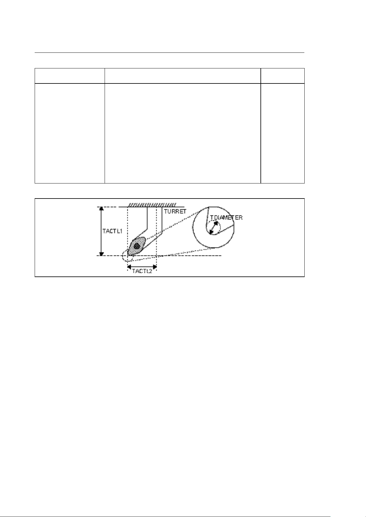
Tool offset table
The tool offset table consists of 300 pages. Each page contains all information describing the
dimensions of a tool. This information is divided into fields:
TACTL1
TCMAXL1
TCACTL1
TACTL2
TCMAXL2
TCACTL2
TDIAMETER
TCACDIAM
TORIENT
1
300
3
2
Fig. 3-8 Tool offset table (one page per offset)
The table contains 300 pages for 300 offset tools. This allows to define more offsets for a single tool.
You can access a page of the tool offset table via the tool offset number corresponding to the page
number (1-300). The tool offset number will be directly programmed into the part program using the
"T" function or can be found in the last field of the tool table (TOLOFNR). Depending on the
application type (milling, lathing or grinding), different fields of the tool offset table will be used. The
following shows all formats of the tables:
10 Series CNC PLUS Application Manual (11) 3-25

Chapter 3
I/O Processor /System Data Areas
Depending on the type of application (mill, lathe or grinder) you will use different tool offset table
fields. All table formats will be shown hereafter:
MNEMONIC CONTENTS MILL FORMAT
TACTL1
TCMAXL1
TCACTL1
TDIAMETER
TCACDIAM
actual tool length
allowable tool length wear
actual tool wear offset
actual tool diameter
actual tool diameter wear
Fig. 3-9 Mill Tool Offset Table
double
double
double
double
double
3-26 10 Series CNC PLUS Application Manual (11)

Chapter 3
I/O Processor /System Data Areas
MNEMONIC CONTENTS GRINDER FORMAT
TACTL1
TCMAXL1
TCACTL1
TACTL2
TCMAXL2
TCACTL2
TDIAMETER *
TCACDIAM
TORIENT
actual tool length 1 (wheel radius)
allowable tool length 1 wear
actual tool length 1 wear
actual tool length 2 (wheel width)
allowable tool length 2 wear
actual tool length 2 wear
actual wheel nose diameter
wheel nose diameter wear
orientation ( wheel orientation angle)
GRINDING WHEEL GEOMETRY
double
double
double
double
double
double
double
double
short
Fig. 3-10 Grinder tool offset table
10 Series CNC PLUS Application Manual (11) 3-27
Chapter 3
I/O Processor /System Data Areas
MNEMONIC CONTENTS LATHE FORMAT
TACTL1
TCMAXL1
TCACTL1
TACTL2
TCMAXL2
TCACTL2
TDIAMETER À
TCACDIAM
TORIENT
actual tool length 1 (length in X axis)
allowable tool length 1 wear
actual tool length 1 wear
actual tool length 2 (length in Z axis)
allowable tool length 2 wear
actual tool length 2 wear
actual tool tip diameter
tool tip diameter wear
orientation ( tool tip orientation angle)
double
double
double
double
double
double
double
double
short
Fig. 3-11 Lathe tool offset table
NOTE:
À The wheel nose radius resp. tool tip radius is internally (table) managed as a diameter.
The entry in the table editor is a radius.
3-28 10 Series CNC PLUS Application Manual (11)

User table
Chapter 3
I/O Processor /System Data Areas
USER1
USER2
USER3
USER4
3
2
1
100
Fig. 3-12 User table
The user table has 100 pages. Each page contains 4 "double" fields. You can read or write to this
table with the page number (index) to select the page and the field name (USERn) to address the
desired field. The use of the fields depends on the requirements of the application. The system never
accesses this table.
One page of the table in detail:
MNEMONIC CONTENTS FORMAT
USER1
USER2
USER3
USER4
user variable 1
user variable 2
user variable 3
user variable 4
double
double
double
double
10 Series CNC PLUS Application Manual (11) 3-29

Chapter 3
I/O Processor /System Data Areas
END OF CHAPTER
3-30 10 Series CNC PLUS Application Manual (11)

Chapter
4
PART PROGRAM INTERFACE
STRUCTURE
A part program block can contain:
• 1 S word to control the spindle speed
• 1T word to control the tool and offset to be used
• up to 4 M words for miscellaneous functions (prelude, postlude and expedite M codes are
supported)
• up to 6 pseudo axes used to transfer information to the logic
• up to 6 motion axes (for coordinated motion)
For each one of these part program information groups the system will activate a routine written by
PLUS programmer. To identify the different routines in correspondence with their specific purpose,
you have to use the DTSK and ETSK statements and pre-assigned routine names (refer to chapter 2).
You do not need to define ALL routines. If the system finds that a certain routine is not available, it
will assume that the logic is not interested in the part program information and continue the execution
of the block.
For each one of the processes, these interfacing routines have to be defined. All routines for one
specific process will be collected by the PLUSGEN utility and combined to one "task".
In this context the word TASK represents a collection of routines having the same priority.
Though optional, some routines like $nMDECOD, $nSPROG and $nTPROG must be defined to be
able to have the 10 Series CNC actually execute M codes, handle spindle, tools, etc.
10 Series CNC PLUS Application Manual (10) 4-1

Chapter 4
Part Program Interface
PART PROGRAM INTERFACE TASK
For each configured process there is one task dedicated to the management of requests coming from
the part program execution. This task is divided into several user-defined routines, each one
dedicated to a certain request. Due to the fact that this task has a higher priority than the background
tasks, it is strongly recommended not to use loops in the single routines but to use the WAIT and
DLY instructions (function blocks for routine interrupt) instead.
All the routines in this task will not be executed cyclically like the background. The execution of a
routine in the interface task is a single shot type execution (S,T, ..... function programming).
If these routines need to communicate with background tasks (e.g. to pass information and wait for a
result) you must synchronize the routine and the background using the WAIT and SEND instructions.
It is very important to remember that in case of HOLD or RESET, a pending part program interface
task has to be released from the wait status. Even if the activity it is waiting for is not completed yet,
the routine must be released.
In the background task we suggest to test the system status flags (S variables SW 20) for hold
and/or reset and if set release the pending interface task using the SEND instruction as shown in the
flow chart below.
4-2 10 Series CNC PLUS Application Manual (10)

Chapter 4
Part Program Interface
Fig. 4-1 HOLD and RESET request during pending interface routine
10 Series CNC PLUS Application Manual (10) 4-3
Chapter 4
Part Program Interface
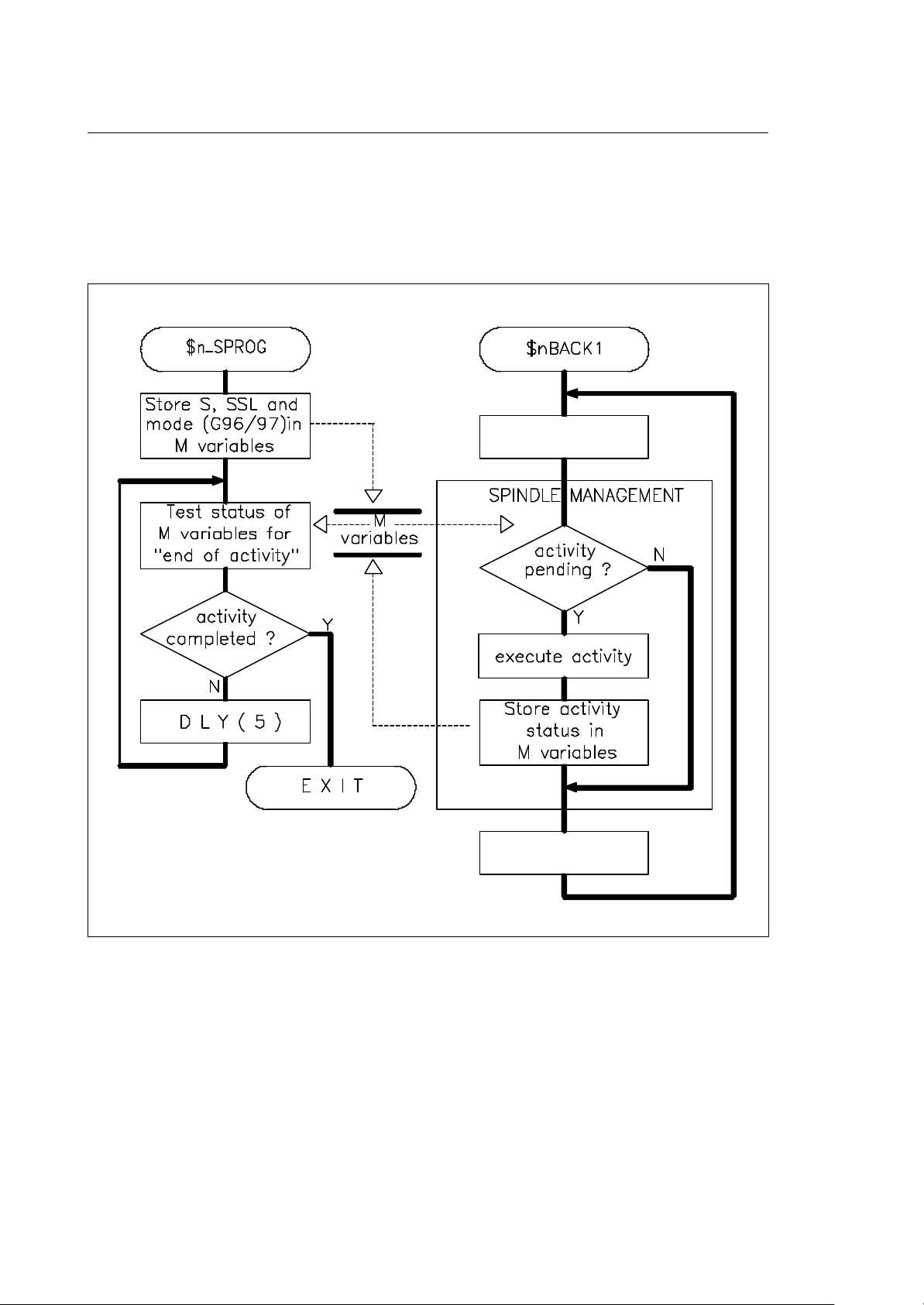
Another technique which can be used to synchronize the interface routine with the background is to
use the DLY instruction. This instruction suspends the execution of the interface routine for the
programmed period of time, thus enabling the background to run and to process the information. After
the time is expired, the interface routine can check if the background finished its process (M variable)
and depending on the result decide to repeat the delay or to release the routine ($nSPROG in the
example of Fig. 4.2).
Fig. 4-2 Alternative synchronization technique
In the previous example the DLY(5) statement suspends the execution of the $nSPROG task for 50
ms before it resumes the execution and tests the completion of the background activity.
4-4 10 Series CNC PLUS Application Manual (10)
Chapter 4
Part Program Interface
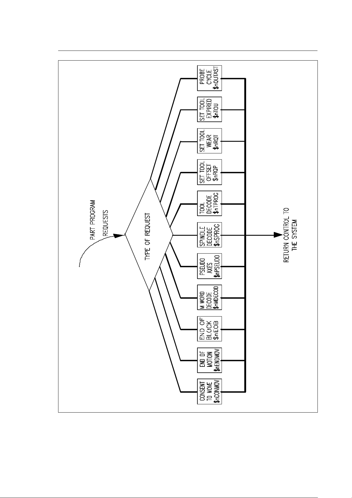
Fig. 4-3 Part program interface routines
10 Series CNC PLUS Application Manual (10) 4-5

Chapter 4
IMPORTANT
Part Program Interface
PART PROGRAM INTERFACE ROUTINES
• Each one of the following routines is executed once every time one of the following conditions is
encountered in the part program:
− axis motion programmed (SnCONMOV, $nENDMOV)
− M word programmed ($nMDECOD)
− S word programmed ($nSPROG)
− T word programmed ($nTPROG)
− pseudo axis programmed ($nPSEUDO)
− End Of Block encountered($nEOB)
− adjust tool dimension offset ($nRQP)
− adjust tool wear offset ($nRQT)
− tool life expired ($nTOU)
− probing cycle completed ($nQUTAST)
• The purpose of these routines is to allow the logic to take the correct actions and to process the
part program information.
• The part program information to be processed is stored in X variables. If there are output variables,
they have to be returned using the X variables. The routine must return an answer (acknowledge/
no acknowledge) in XW 00.
• XW 00 has to be used to return an answer to the system:
0 = acknowledge to the system
-1 = error
• XW01 and XW02 are reserved and must not be modified
• All routines are optional. If they are not present, they will not be called. In some cases the system
executes some minimal action. If routines are not defined, the system will assume an
acknowledge and continue the execution of the part program.
The input parameters to the task are reserved locations which may not be
changed (except where specifically allowed).
4-6 10 Series CNC PLUS Application Manual (10)

Part Program Interface
SEQUENCE OF PART PROGRAM INFORMATION TRANSFER TO THE LOGIC
In point-to-point-mode (G0 or G29) the block words are send to the logic in the following order:
Chapter 4
Fig. 4-4 Sequence of part program to PLUS information transfer
10 Series CNC PLUS Application Manual (10) 4-7

Chapter 4
Part Program Interface
COORDINATED AXES
There are 9 possible motion axes in a process. Six out of 9 axes can be programmed in a part
program block. In case of dual axes, you can have up to 9 axes moving with only 6 axes programmed
in the block. Each of the axes has a part program address (axis name) which must be defined in
AMP. The numerical value which is programmed after that address ( the position) is a (double
precision) floating point number which has a format of 5.5.
Related to the coordinated axes motion there are two calls from the system to the logic:
• Consent to move $nCONMOV
• End of motion $nENDMOV
Consent to move routine
$nCONMOV
This routine is always called when a coordinated axis in a process has to be moved. There only
exception is when the axis has to be moved by the handwheel.
The logic has to check if this axis is allowed to move. The axis motion will not be started until the
logic responds with an acknowledge in the local variable XW 00.
The $nCONMOV routine must be defined with:
DTSK $nCONMOV
Consent to move program block
ETSK
INPUT VARIABLES:
XW 03 Type of motion (short)
XW 04 Type of fixed cycle (short)
XW 05 mode (short)
XW 06 axis identifier of 1st visualised axis (short)
.
XW 14 axis identifier of 9th visualised axis (short)
XD 00 programmed feedrate (double)
XD 01 end position of 1st configured axis (double)
.
XD 09 end position of 9th configured axis (double)
OUTPUT VARIABLE:
XW00 task return value (short)
4-8 10 Series CNC PLUS Application Manual (10)

Chapter 4
G
Part Program Interface
G29
G28
G27
15 00
Fig. 4-5 Consent to move /type of move
15 00 Bit
G72
G73
G74
Fig. 4-6 Consent to move /type of canned cycle
Bit
XW 03
RAPID (G00)
LINEAR (G01)
CIRCULAR (G02, G03)
XW 04
G81
G82
G83
G84
G85
G86
RESERVED
RESERVED
G89
P-P BLOCK
MAS BLOCK
15 00Bit
XW 05
CONTUNOUS MANUAL JO
INCREME NTAL JOG
HOME
RESERVED
RESERVED
JOG RETURN
RESERVED
RESERVED
Fig. 4-7 Consent to move/mode
10 Series CNC PLUS Application Manual (10) 4-9

Chapter 4
Part Program Interface
Motion blocks
A motion block is a part program block or a group of part program blocks containing programmed
axes motion from the actual point to the programmed end point without any commanded stop inside
the motion.
A motion block can be:
• an axis move in G00
• a programmed move in G01, G02 or G03
• a continuous path (profile) in G27 or G28. In this case the motion block may consist of more than
one part program block.
• a fixed cycle (like G81, G83, etc.)
• a fixed cycle like G84 or a part program block in G33
The system notifies the logic at the beginning of a motion block by starting the consent to move
routine in the system interface task ($nCONMOV). At the end of the motion block the logic will again
be notified, this time via the $nENDMOV routine in the interface task.
All the axes which will be used inside the motion block must be declared in the first part program
block describing the motion block. In case of a motion block in continuous, this means that the first
block must contain all axes involved in this motion, be it just repeating the actual position. Only in
this way the system can inform the logic about the axes involved in the motion block.
Example:
G 00 X 10 Y 10 Z 10
G 01 G 27 X 20 Y 20 Z 10 F 1000 <-- Z declared even if
MOTION X 30 no motion in this
BLOCK Y 30 pp bloc k
Z 30
G 29 X 40 Y 40 Z 30
4-10 10 Series CNC PLUS Application Manual (10)

Chapter 4
Part Program Interface
Consent to move management
Every time a motion block is encountered, the system "asks consent" to the logic, specifying the
axes involved, the motion type, the end points and the programmed velocity on the profile. The
maximum number of axes allowed in a process is 9.
Fig. 4-8 Consent to move signal flow
NOTE:
It is suggested to save the specified axis identifiers in local variables in order to be able to use this
information at the end of the motion during the execution of the $nENDMOV routine.
When using $nCONMOV, you must also include $nENDMOV in your logic. If you have no practical
use for $nENDMOV, just include the statements needed to return a 0 value in XW 00.
10 Series CNC PLUS Application Manual (10) 4-11

Chapter 4
Part Program Interface
End of motion routine
$nENDMOV
This routine (if defined) is called every time a motion block has been completed.
The routine must be defined as follows:
DTSK $nENDMOV
End of motion management routine
ETSK
INPUT VARIABLES:
XD reserved (double)
OUTPUT VARIABLES:
XW00 task return value (short)
4-12 10 Series CNC PLUS Application Manual (10)
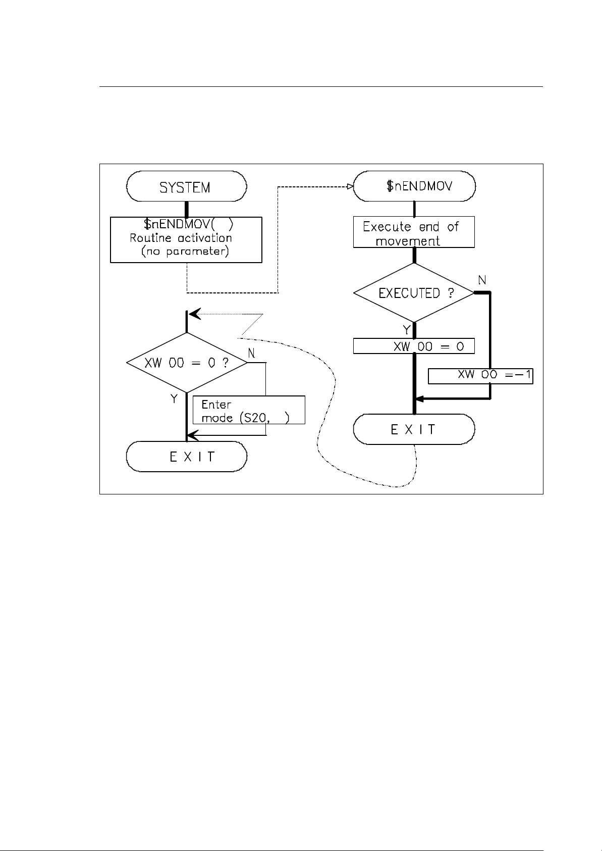
Chapter 4
Part Program Interface
End of move management
At the end of a motion block the system will inform the logic. The logic can take the appropriate
action before releasing the system.
error
5
Fig. 4-9 End of motion flowchart
When you send a NACK (-1) in XW 00, the control will go in ERRO condition.
After giving a RESET command, the system exits the error status.
10 Series CNC PLUS Application Manual (10) 4-13

Chapter 4
Part Program Interface
M FUNCTIONS
The M word followed by a number identifies an auxiliary function relative to the machine tool. In the 10
Series CNC the M word value must be a positive integer with up to 3 digits (0...999). The
programming format for the M word is therefore (M0.....M999). You can program up to 4 M codes in a
part program block.
M functions may have different characteristics, which must be specified in the AMP. There are 3
types of M functions:
• Prelude M functions are sent to the logic before axes motion
• Expedite M functions are sent to the logic during axes motion
• Postlude M functions are sent to the logic after axes motion
In prelude and postlude M functions synchronization between axes moves and execution of M's by
the machine logic depends on:
• how the accepted in continuous mode parameter has been configured
• the type of move (G27, G28 or G29)
Motion Code accepted in continuous mode = N accepted in continuous mode = Y
G27-G28 no synchronization M function execution synchronized
with axes moves. No handshake
required (the function is sent to the
logic without interrupting program
execution).
G29 M function execution synchronized
with axes moves. Handshake
required (program execution
interrupted as long as it is requested
by the logic).
4-14 10 Series CNC PLUS Application Manual (10)

Chapter 4
Part Program Interface
M decode routine
$nMDECOD
This routine is called every time a M function is encountered in the part program. The logic has to
process the M function and acknowledge to the request when the execution of the M function has
been completed.
Routine definition:
DTSK $nMDECOD
Source code for M decode routine
ETSK
INPUT VARIABLES :
XW 03 type of M code (short)
XW 04 decimal value of M code (short)
OUTPUT VARIABLES:
XW 00 task return value (short)
Description:
The type of M code (XW 03) can assume following values:
0 => prelude M code
1 => expedite M code
2 => postlude M code
M words are passed to the routine $nMDECOD in the same sequence as they were programmed in
the part program block. The routine will be activated once for every single M .
10 Series CNC PLUS Application Manual (10) 4-15

Chapter 4
Part Program Interface
Fig. 4-10 M code management (postlude/prelude) in point to point mode
The logic has the possibility to acknowledge the M code request or to refuse it. If for example a
certain M code is not allowed in the actual state of the machine, the logic can return a -1 value in the
XW 00 variable. The system will go in error state. Another reason to refuse an M code could be a
mechanical problem during its execution.
4-16 10 Series CNC PLUS Application Manual (10)

Chapter 4
Part Program Interface
When a RESET coincides with the execution of an M code, the logic must acknowledge to the
system anyway. The logic may decide to abort or to continue the further execution of the M code.
Never forget to acknowledge a pending M code during a reset, because this will block the system and
prevent the reset from being completed.
Note that the acknowledge to the system for the M code has to be executed before you can call the
$ENDRESE function. For more details refer to the reset management.
When a HOLD coincides with the execution of an M code, the system will not execute any further
(MDI) M-codes, until it receives the acknowledge for the pending M code.
On entry in the hold status, the logic has to save the status of the M functions. On exit from HOLD
the logic can then restore the previous state. For more details see the hold management.
SYSTEM
$nMDECOD (value)
PLUS routine activation
other
M functions
?
continue block
processing
$nMDECOD
M function
allowed
EXECUTE
M function
EXIT
enter error status
(S20,05)
EXIT
Fig. 4-11 M code management (postlude/prelude) in continuous mode
10 Series CNC PLUS Application Manual (10) 4-17

Chapter 4
Part Program Interface
M code management (EXPEDITE)
The system allows the use of only one expedite M function in each part program motion block. The
expedite M code will be passed to the $nMDECOD routine.
Because there is no synchronization for expedite functions, expedite M codes must be processed by
the logic as fast as possible. The throughput of part program blocks containing an expedite function
may be very high (block cycle time!). By making the execution as fast as possible, you minimize the
change to miss expedite M codes at high part program block rates.
Fig. 4-12 Expedite M code management in continuous mode
4-18 10 Series CNC PLUS Application Manual (10)

Chapter 4
Part Program Interface
AMP set up for M functions
Each M function allowed in the system has to be set up in the AMP software configuration program.
The characterization for M codes is used by the system when an M code is encountered in the part
program. When you program an M code which was not defined in AMP, you will get an error.
This is the list of items which can be assigned to M codes in AMP:
Activation mode: PRELUDE / POSTLUDE / EXPEDITE
This attribute tells the system when to notify the logic about the M
code. Prelude means before the motion of the block starts,
postlude is after the motion of a block has been finished and
expedite means that the logic will be notified during the motion.
(i.e. M03, spindle clockwise, will have the attribute prelude, M 06,
change tool and tool offset, will be executed postlude)
Allowed in hold: Y/N
This attribute tells the system that the related M function can or
cannot be executed and notified to the logic in the hold status.
M06 is an example of a code which cannot be accepted in hold.
Visualization: Y/N
This attribute defines whether or not the system will display the M
code on the main screen.
Modal function: Y/N
This attribute refers to the display of an M code. If you declare the
function modal, its code will be displayed also during all
consequent blocks. A non-modal function will only be displayed
during the execution of the block it was programmed in. ( i.e M03
is modal, M06 is not)
Display after reset: Y/N
This attribute tells the system if the display of the M code must be
maintained after a reset. When set, also the logic has to maintain
that M function active, even if a reset occurs.
Force conditional blk/blk: Y/N
This attribut e can be set true for postlude M functions only. When
an M code with this attribute is executed and the system variable
USO is set true, the system will go in "block by block" mode at the
end of the block. You can define the state of "USO" in the "PART
PROGRAM SETUP" menu. This attribute is normally used for the
M01 (optional stop) code.
Force unconditional blk/blk: Y/N
This attribute can be set true for postlude M functions only. When
an M code with this attribute is executed, the system will go in
"block by block" mode at the end of the block containing the M
code. This attribute is normally used for the M00 (programmed
stop) code.
10 Series CNC PLUS Application Manual (10) 4-19

Chapter 4
Part Program Interface
Block calculation stop: Y/N
This attribute can be set true for postlude M functions only. When
an M code with this attribute is executed, the pre-calculation of the
next part program block is stopped. In this status, the system can
accept other motion commands from the logic, like MDI or
subroutine calls (i.e. to execute a M60 pallet change with motion of
the coordinate axes). The normal part program execution after a
block calculation stop can be resumed with the $PPRESUME
function call.
Tool offset change: Y/N
This attribute can be set true for postlude M functions only. When
an M code with this attribute is executed, the system will be
prepared for a change of the tool offset. It must always be
combined with "block calculation stop=Yes". This attribute is
normally used for the M06 tool change M code.
Reset after execution: Y/N
This attribute can be set true for postlude M functions only. When
an M code with this attribute is executed, the system will
automatically perform a RESET at the end of the block. Normally
this attribute is used for codes like M02 or M30 (program end).
Display class: 0....15
This attribute tells the system how the M codes must be grouped
for their display on the screen. For example the codes M03, M04
and M05 belong to the same group, are mutually exclusive and can
be displayed in one screen position.
During their execution, M codes will appear on the screen in
reverse video mode. In the moment in which the logic
acknowledges the M code, the display of the M code will be turned
normal.
4-20 10 Series CNC PLUS Application Manual (10)

Chapter 4
Part Program Interface
Fig. 4-13 Display Class explained in an example
Search in memory class: It defines the priority in the emission of the M function at the end of
the search in memory command.
There are 16 classes of priority. The priority class will guide the
emission of the M function; at the end of the search in memory
command the highest priority M function will be emitted, followed
by those of lower priority. A priority class 0 means that the M
function will not be memorised and consequently will not be
emitted at the end of the search in memory command.
Accepted in continuous mode: Y/N
This parameter specifies whether or not the M function may be
programmed continuous mode. It can be set to Y only for functions
that do not require "forces block to block", "calculation stop",
"offset change" or "reset".
10 Series CNC PLUS Application Manual (10) 4-21

Chapter 4
Part Program Interface
Fig. 4-14 M Execution in point to point mode (prelude)
4-22 10 Series CNC PLUS Application Manual (10)

Chapter 4
Part Program Interface
Fig. 4-15 Expedite M execution in point to point mode
10 Series CNC PLUS Application Manual (10) 4-23

Chapter 4
Part Program Interface
Fig. 4-16 Postlude M execution in point to point mode
4-24 10 Series CNC PLUS Application Manual (10)

Chapter 4
Part Program Interface
PSEUDO AXES
Pseudo axes offer an easy-to-handle interface between the part program and the logic. The pseudo
axes are part program addresses (like axes addresses) which can be used to transfer numerical
information (in double precision floating point format) to the PLUS program. This information can be
used by the logic to control analog outputs or point-to-point-axes.
The part program addresses (axes names) of the pseudo axes must be defined in the AMP
configuration utility. AMP will allow you to configure up to 6 addresses as pseudo axes. The names
used must be different from the other axes names. The programming format for pseudo axes (like for
normal axes) is 5.5.
Pseudo axes routine
$nPSEUDO
This routine is called every time a pseudo axis is encountered during part program execution.
In addition, the system sends the logic the ID and the value associated to the programmed pseudo
axis as follows:
• if the program is being executed in point to point mode, the system interrupts execution and
waits for a response from the logic;
• if the program is being executed in continuous mode, the system neither interrupts execution nor
waits for a response from the logic.
The pseudo axes routine can be defined using the following statements:
DTSK $nPSEUDO
Pseudo axes management program
ETSK
INPUT VARIABLES:
XW 03 axis identifier for the first confi gured pseudo axis (short)
..... .........
XW 08 axis identifier for the sixth configured pseudo axis (short)
XD 00 programmed value for the first pseudo axis (double)
..... .........
XD 05 programmed value for the sixth pseudo axis (double)
OUTPUT VARIABLE:
XW00 task return value (short)
10 Series CNC PLUS Application Manual (10) 4-25

Chapter 4
Part Program Interface
If the value of a pseudo axis identifier (one of the parameters from XW 03 through XW 08) is zero
value, then the corresponding pseudo axis is not programmed in that block. The sequence of the
pseudo axes addresses in the words XW 03 through XW 08 is the same as that of the sequence
configured in AMP.
Axes identifiers can have the following values:
Process 1 First axis
Second axis
..................
Sixth axis
Process 2 First axis
..................
Process 3 First axis
..................
Process 4 First axis
..................
Process 5 First axis
...............................
Process 6 First axis
...............................
Process 7 First axis
...............................
Process 8 First axis
...............................
Process 9 First axis
...............................
Process 10 First axis
...............................
Process 11 First axis
...............................
Process 12 First axis
...............................
Process 13 First axis
...............................
Process 14 First axis
...............................
Process 15 First axis
...............................
Process 16 First axis
...............................
Process 17 First axis
...............................
Process 18 First axis
...............................
Process 19 First axis
...............................
Process 20 First axis
...............................
Identifier = E100H (57600T)
Identifier = E101H (57601T)
............
Identifier = E105H (57605T)
Identifier = E200H (57856T)
............
Identifier = E300H (58112T)
............
Identifier = E400H (58368T)
............
Identifier = 0E500H (58624T)
...............................
Identifier = 0E600H (58880T)
...............................
Identifier = 0E700H (59136T)
...............................
Identifier = 0E800H (59392T)
...............................
Identifier = 0E900H (59648T)
...............................
Identifier = 0EA00H (59904T)
...............................
Identifier = 0EB00H (60160T)
...............................
Identifier = 0EC00H (60416T)
...............................
Identifier = 0ED00H (60672T)
...............................
Identifier = 0EE00H (60928T)
...............................
Identifier = 0EF00H (61184T)
...............................
Identifier = 0F000H (61440T)
...............................
Identifier = 0F100H (61696T)
...............................
Identifier = 0F200H (61952T)
...............................
Identifier = 0F300H (62208T)
...............................
Identifier = 0F400H (62464T)
...............................
4-26 10 Series CNC PLUS Application Manual (10)

Chapter 4
Part Program Interface
Fig. 4-17 Pseudo axes management in point to point mode
10 Series CNC PLUS Application Manual (10) 4-27

Chapter 4
Part Program Interface
SYSTEM
$nPSEUDO
$nPSEUDO(ax_id1,value1,
.... ax_id3,value3)
continue block
processing
enter error status
(S20,05)
process pseudo
axes value
VALUES
OK ?other axes ?
EXIT
EXIT
Fig. 4-18 Pseudo axes management in continuous mode
4-28 10 Series CNC PLUS Application Manual (10)

Chapter 4
Part Program Interface
S WORD
The part program uses the letter "S" as an address for the spindle value. The S address can be used
to program the spindle speed in RPM or the workpiece (grinding wheel) surface speed. In the latter
case the units of the value programmed under S must be defined by the programmer of the logic
(normally the surface speed is expressed in m/min or feet/min but for grinders also m/s and feet/s are
used).
In case the G code G97 is active, the spindle is expected to be programmed in RPM, for G96 the
programmed value is a surface speed.
The S word is a floating point number (double precision) with a programming format of "6.3", i.e. the
number may have up to 6 significant digits before the decimal point and up to 3 significant digits after
the decimal point. In this way the 10 Series CNC is able to support all kinds of spindles from large
reaming heads up to high frequency spindles.
The S word handling will be discussed in detail later in this chapter.
S decode routine
$nSPROG
This routine is called every time an S function is encountered during part program execution.
In addition, the system sends the logic the ID and the value associated to the programmed pseudo
axis as follows:
• if the program is being executed in point to point mode, the system interrupts execution and waits
for a response from the logic;
• if the program is being executed in continuous mode, the system neither interrupts execution nor
waits for a response from the logic.
This routine can be defined with the following statements:
DTSK $nSPROG
S code management program
ETSK
INPUT VARIABLES:
XD 00 S word value as programmed (double)
XD 01 SSL spindle speed limit value (double)
XD 02 - In G96 mode:
S function value in the active measuring unit (mm or inch)
- In G97 mode:
S function value as programmed (rpm)
XW 03 Spindle control G code 0 = G97 1 = G96 (short)
OUTPUT VARIABLES:
XW00 task return value (short)
10 Series CNC PLUS Application Manual (10) 4-29

Chapter 4
Part Program Interface
The value of XD02 can be used directly as an input parameter in functions:
$SG96RPM or $G97RPM.
With $SG96RPM it is normally assumed that S is programmed in m/min (G71) or Feed/min (G70).
Should other measure units be utilized such as Feed/s or m/sec, the appropriate conversions must
be made in the logic program starting from the programmed speed value (XD0).
The S value is passed to the logic through the $nSPROG routine (Fig. 4.19).
Handling the percentage spindle speed override (SS0) is one of the machine logic tasks.
Two methods are available to the logic user for handling these variations (for example, after the
relevant softkeys are pressed):
• Check any variation recorded in the value of variable S_nSS0 (SW37) by comparing the current
value with the previously stored one
• Write the filter routine $n_PUTSPE; in this way the routine is transmitted to the logic in the routine
filter in variable XW3.
In both cases, the value of SS0 is given by the value, multiplied by 100.
SS0 Value value %
0
1000
10000
Therefore, if the user wishes to utilize SS0 that is the speed value supplied by routine $n_SPROG
after being converted in the correct measuring unit, must be multiplied by the percentage value.
The value obtained can be given as in input to function $SG96RPM or $SG97RPM.
Example:
SSO 1000 (10%)
SPINDLE SPEED 1500 RPM
New Spindle Speed value =
1500
1000
10000
0
10
100
150 revolution /min× =
[ ]
4-30 10 Series CNC PLUS Application Manual (10)

SYSTEM
Chapter 4
Part Program Interface
$nSPROG
$nSPROG (value)
PLUS routine activation
enter error status
(S20,05)
S execution
VALUES
OK ?
EXIT
EXIT
Fig. 4-19 FUNCTION S management in point to point mode
10 Series CNC PLUS Application Manual (10) 4-31
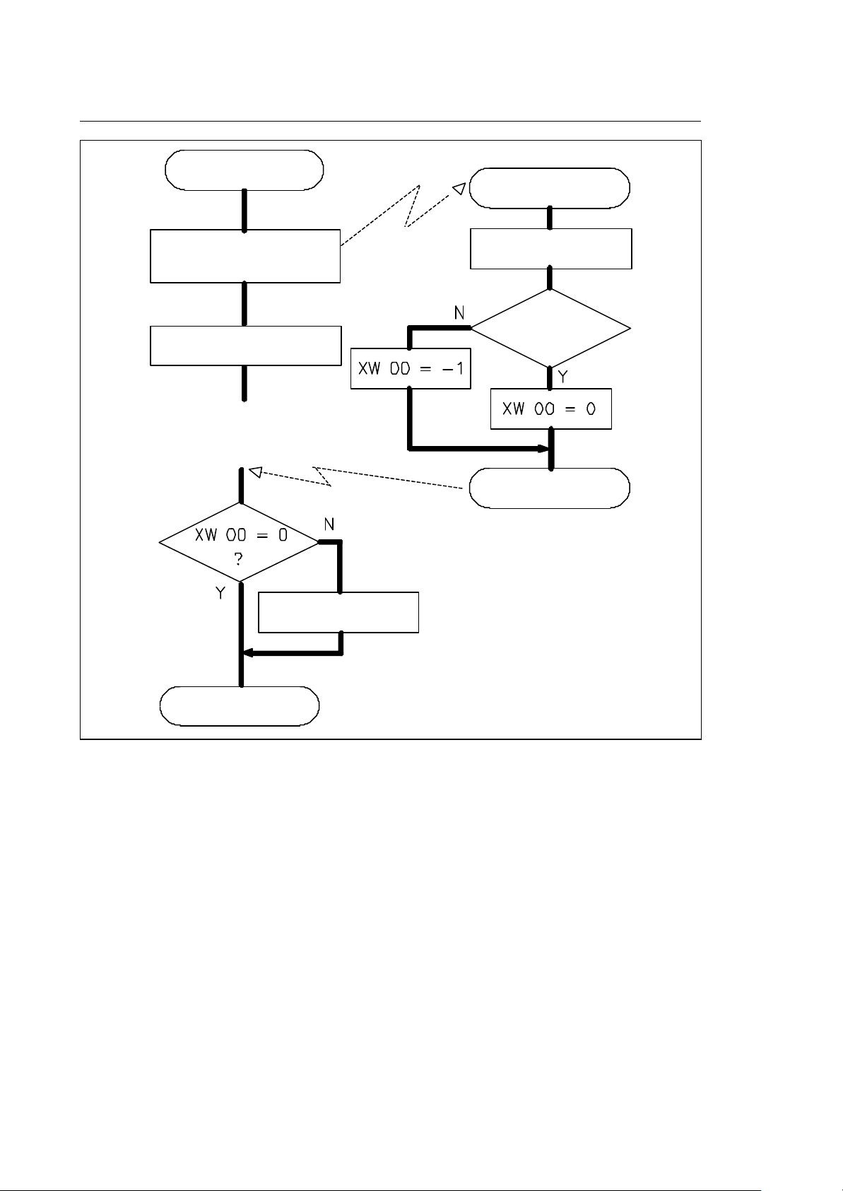
Chapter 4
Part Program Interface
SYSTEM
$nSPROG
$nSPROG (value)
PLUS routine activation
continue block
processing
enter error status
(S20,05)
S execution
VALUES
OK ?
EXIT
EXIT
Fig. 4-20 S management in continuous mode
NOTE:
The spindle speed is displayed on the screen with two values:
• Programmed speed (S programmed)
• Actual speed:
− spindle with transducer
actual spindle RPM will be displayed
− spindle without transducer
the displayed spindle speed will be calculated by the system from the programmed value, the
spindle speed override percentage, the SSL and the active G code.
4-32 10 Series CNC PLUS Application Manual (10)
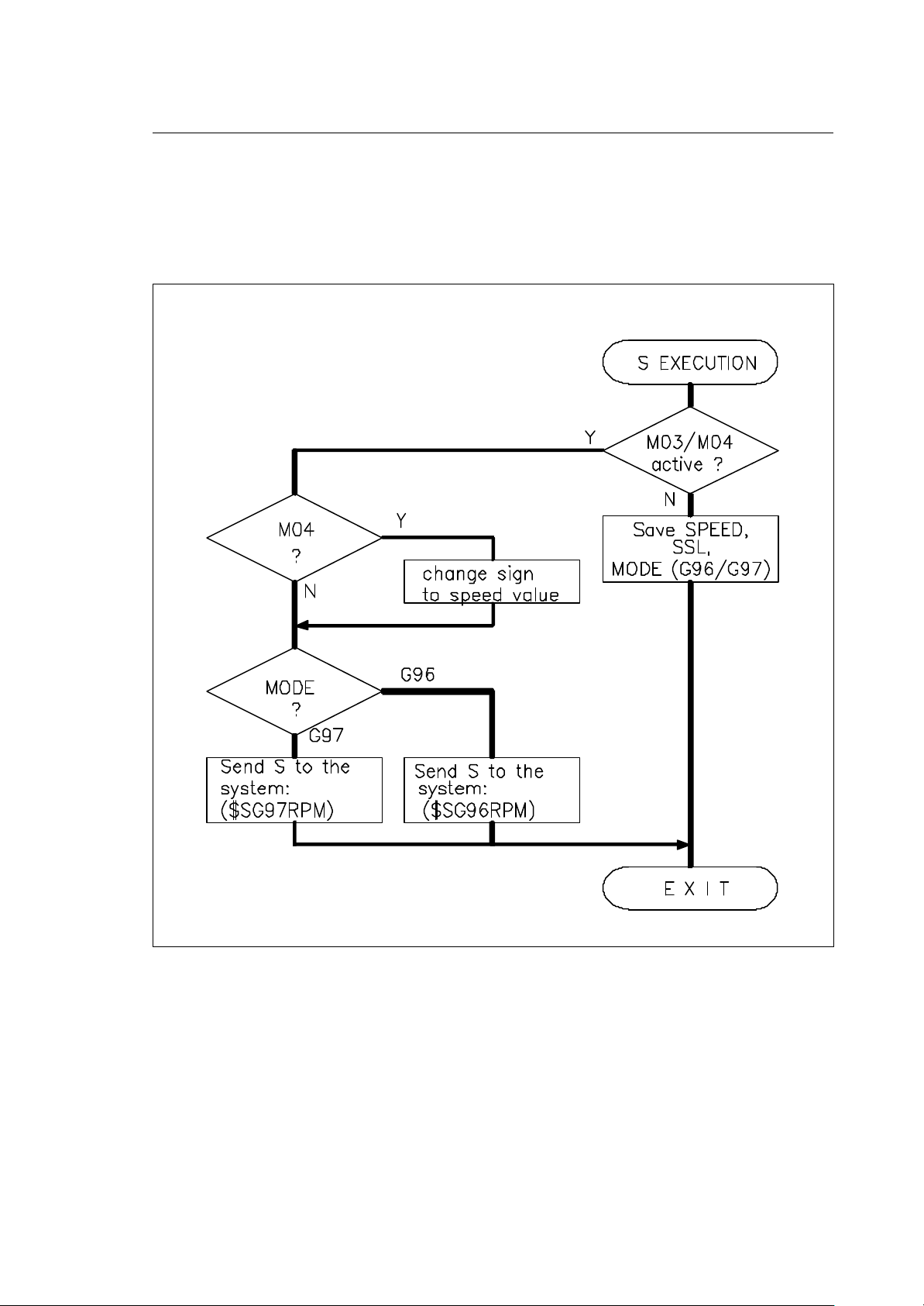
Chapter 4
Part Program Interface
The logic must release the $nSPROG routine by sending an acknowledge to the system. In case of a
reset during the execution of this routine, the acknowledge should be given immediately. What
happens to the spindle in case of a reset depends on the type of application.
The system must be released before you can use the function call $ENDRESE. For more details on
RESET please refer to the "RESET" chapter.
Fig. 4-21 S processing by the logic
NOTE:
The above figure does not take into consideration the value of SS0.
10 Series CNC PLUS Application Manual (10) 4-33

Chapter 4
Part Program Interface
T WORD
The T part program address is used to transfer up to two values to the logic. The first value is the tool
identification code, a positive integer number of up to 12 digits, which is handled using the "double"
format. The second value is the tool offset number. This is a positive integer number with a "short"
format. Its range is 0..300. Both values, tool identification and offset number must be separated by a
point "." character when using the T code in the part program.
The programming format for the T word is therefore
Txxxxxxxxxxxx.yyy
The tool identification code is used to determine the tool table page where required data can be found.
Page identification can be done in two ways:
• programmed tool identifier corresponds to the page number (T250)
• tool identifier is a symbol that allows to find the correct page
The following descriptions are valid for both cases except for tool table search that is valid only for the
second case.
It is possible to express 6 types of T function representation, each with a different meaning.
T xxxxxxxxxxxx (only tool id code xxxxxxxxxxxx)
Insert a new tool. The logic has to search in the tool table for the
programmed tool id. Once it has found the page which contains the tool, it
must read the tool offset number (TOLOFNR) from the same page, change
the tool and activate the offset. Normally you use a tool change M code in
the part program (typically M06) to physically execute the tool change and
to activate the offset.
T 12345
n + 2
n + 1
n
67
TCODE TOLOFNR
12345 67
Tool Offset Table
69
68
Tool offset # 67
Tool Table
Fig. 4-22 Search for programmed tool and offset
4-34 10 Series CNC PLUS Application Manual (10)

T .yyy or T 0.yyy (only tool offset number yyy)
Activate a new tool offset for the actual tool in the spindle. The logic uses
the tool offset number as a pointer to the tool offset table. The tool offset
number is the page number containing that offset. You can use a tool
change M code like M06 in the part program to tell the logic to activate this
offset.
T .67
Tool Offset Table
69
68
67
Tool offset # 67
Fig. 4-23 Search for the offset number
T xxxxxxxxxxxx.yyy (tool id code xxxxxxxxxxxx + offset number yyy)
Chapter 4
Part Program Interface
Insert a new tool. The logic has to search in the tool table for the
programmed tool id. It must then use the programmed tool offset number to
activate the required offset. On a tool change M code in the part program
(typically M06), the logic has to change the tool and to activate the offset.
T 12345.67
Tool Table
n + 2
n + 1
n
67
TCODE TOLOFNR
12345
Tool Offset Table
69
68
Tool offset # 67
33
Fig. 4-24 Programmed tool and tool offset
10 Series CNC PLUS Application Manual (10) 4-35

Chapter 4
Part Program Interface
T xxxxxxxxxxxx.0 (tool id code xxxxxxxxxxxx without tool offset)
Insert a new tool in the spindle. The logic has to search in the tool table for
the programmed tool id. The tool offset has to be forced to a zero value.
T 12345.0
Tool Table
n + 2
n + 1
n
TCODE TOLOFNR
12345
33
Fig. 4-25 Programmed tool without offset
T .0 (remove actual tool offset)
The logic has to set the tool offset to a zero value. The tool remains in the
spindle.
T 0 or T 0.0 (remove actual tool and tool offset)
The logic has to set the tool offset to a zero value. The tool must be
removed from the spindle.
4-36 10 Series CNC PLUS Application Manual (10)

Chapter 4
Part Program Interface
T decode routine
$nTPROG
This routine is called every time a T function is encountered during part program execution.
In addition, the system sends the logic the parameters associated to the programmed T as follows:
• if the program is being executed in point to point mode, the system interrupts execution and waits
for a response from the logic;
• if the program is being executed in continuous mode, the system neither interrupts execution nor
waits for a response from the logic.
The routine must be defined with the following statements:
DTSK $nTPROG
Body of T decode routine
ETSK
INPUT VARIABLES:
XW 03 Tool control word (short)
XW 04 Tool offset number (short)
XW 05 Number of axes for offset (1-2) (short)
XW 06 identifier of first axis (short)
XW 07 identifier of second axis (short)
XW 08 Slave tool number (short)
XD 00 Tool identification code (double)
XD 01 reserved (double)
XD 02 cosine for first axis' offset (double)
XD 03 cosine for second axis' offset (double)
OUTPUT VARIABLES:
XW 00 task return value (short)
10 Series CNC PLUS Application Manual (10) 4-37

Chapter 4
Part Program Interface
Description:
The tool control word XW 03 tells your logic how it should handle the information from the X variables.
Twelve programming modes are available, 6 monotool type and 6 multitool. Possible values for the
control word in monotool mode are:
1 - T (tool identifier) change tool/offset from table
2 - T (tool identifier).(offset number) change tool but use specified offset
3 - T (tool identifier).0 change tool but no offset
4 - T .0 remove tool offset
5 - T 0 or T 0.0 remove tool and offset
6 - T .(offset number) or
T 0.(offset number) leave tool but change offset
Refer to Fig. 4.28 which shows how these cases are managed by the system.
The values for the control word in multitool mode range from 11 to 16. The essential difference
between the two programming types is that in multitool mode the value of control word XW 08 is the
number of slave tools specified in the T function.
The variable XW 04 contains the number of the offset (= page number of the tool offset table) which
has to be applied or a zero value if no offset was programmed.
XW 04 has no meaning in case 1.
XW 05 tells your logic program whether the offset has to be applied to one or two axes the identifiers
of which are supplied in XW 06 and XW 07.
The value of XW 08 can be used in multitool programming as the $TOOL_RD F. B. required for
reading the value of the slave tools programmed in the T function.
The variable XD00 contains the tool identification code as programmed in the active part program
block. This code is a number of up to 12 digits which must be used in conjunction with the function
$TBLSRCD to find the page of the tool table containing this tool's data.
The variables XD 02 and XD 03 finally pass a cosine value for each one of the axes involved in the tool
offset. This cosine value has to be multiplied with the tool length offset for that axis as read from the
tool offset table. The 1.0 and 2.0 versions of the control supports only 2 values, either 1.0 or -1.0. If
you want to use the standard offset handling, you have to pass these two cosine values to the
function $TOOLACT (function block TOOLACT).
4-38 10 Series CNC PLUS Application Manual (10)

Chapter 4
Part Program Interface
Fig. 4-26 T code management in point to point mode
10 Series CNC PLUS Application Manual (10) 4-39

Chapter 4
Part Program Interface
SYSTEM
$nTPROG
SnTPROG (T control word, T code,
offset, #axes, ax_id1, ax_id2)
continue block
processing
enter error status
(S20,05)
process T code
Tool found ?
EXIT
EXIT
Fig. 4-27 T code management in continuous mode
4-40 10 Series CNC PLUS Application Manual (10)

Chapter 4
Part Program Interface
Fig. 4-28 T code execution with POCKET search
10 Series CNC PLUS Application Manual (10) 4-41

Chapter 4
Part Program Interface
Fig. 4-29 M 06 execution with new tool offset
4-42 10 Series CNC PLUS Application Manual (10)
 Loading...