


10 Series CNC
Software Release 7.5.4
Installation Manual
Code: 45006687N
Rev. 18
PUBLICATION ISSUED BY:
OSAI S.p.A.
Via Torino, 14 - 10010 Barone Canavese (TO) – Italy
Phone: +39-0119899711
Web: www.osai.it
e-mail: sales@osai.it
service@osai.it
Copyright 2001-2006 by OSAI
All rights reserved
Edition: April 2006
IMPORTANT USER INFORMATION
This document has been prepared in order to be used by OSAI. It describes the latest release of
the product.
OSAI reserves the right to modify and improve the product described by this document at any time
and without prior notice.
Actual application of this product is up to the user. In no event will OSAI be responsible or liable for
indirect or consequential damages that may result from installation or use of the equipment
described in this text.

abc

UPDATE
10 Series CNC Software Installation Manual
SUMMARY OF CHANGES
General
This document was published following the issue of Software Release 7.5.4 (E69); it contains
information about the new functions of the 10 Series CNC.
NOTE:
This document contains the updates related to the issue of Software Release 7.5 (FIXUP 4) and to
the management of the 10 Series Systems, based on CPU PROX-1635.
PAGE TYPE OF MODIFICATION
INDEX
PREFACE
CHP. 0
CHP. 1
Page 1
Updated
Summary and all references to the software release updated
Added a new chapter “Important warnings”
All references to software release updated
Updated note
CHP. 3 New chapter describing changes and improvements introduced with
the new release
APP. A
Page 3
APP. D
Updated compatibility tables
Modified description in the paragraph “Mass storage size compatibility”
Updated appendix containing a list of changes compared to earlier
releases.
At the end of the description of each Release (from release 6.0 on), added
the relative table as given in Appendix A.
10 Series CNC Software Installation Manual (18)

abc
abc

Preface
10 Series CNC Software Installation Manual
PREFACE
This manual describes the methods for correct installation of release 7.5 on 10 Series CNC
systems, the new features and the differences from the previous release, so that operators can
tune their systems to obtain optimum performance.
We have written this manual for OEM and end user personnel charged with installing,
characterising and developing system applications.
REFERENCES
For more information about 10 Series read the following:
• 10 Series CNC User Manual
• 10 Series CNC AMP - Software Characterisation Manual
• 10 Series CNC Programming Manual
• 10 Series CNC PLUS Language and PLUSEDIT
• 10 Series CNC PLUS Application Manual
10 Series CNC Software Installation Manual (17) 1

Preface
10 Series CNC Software Installation Manual
SUMMARY
This manual provides the operator with procedures for correct SW installation, a brief description of
the feature enhancements of the new release, and the major differences with respect to previous
release.
1. Installation
Describes SW installation procedures
2. OSAI security
Contains a description of the E69 software option, OSAI Security.
3. Modifications and enhancements introduced with release 7.5
Contains a description of the new features and the improvements on the previous release
A. Options compatibility tables
B. Error messages
Lists the error messages displayed by the system during installation
C. Instructions for CNC Set-up
Contains a description of the setup utility for selecting the type of Operator Panel connected to
the basic unit.
D. Summary of modifications made with earlier releases
Contains a description of the new functions or enhancements introduced on 10 Series
systems with releases earlier than 7.5.
2 10 Series CNC Software Installation Manual (17)
Preface
10 Series CNC Software Installation Manual
GENERAL CONVENTIONS
Following are a number of terms used in this document:
Control is the 10 Series numerical control system with front panel and basic unit.
Front Panel is the machine/operator interface module. It has a monitor where all
messages are displayed and a keyboard for data inputs. It is connected
to the basic unit.
Basic Unit is the hardware-software unit that handles the machine functions. It is
connected to the front panel and the machine tool.
WARNINGS
For correct control operation, it is important to follow the information given in this manual. Take
particular care with topics bearing one of the mentions: WARNING, CAUTION or IMPORTANT,
which indicate the following types of information:
WARNING
CAUTION
IMPORTANT
Draws attention to facts or circumstances that may cause damage to the
control, to the machine or to operators.
Indicates information to be followed in order to avoid damage to equipment
in general.
Indicates information that must be followed carefully in order to ensure full
success of the application.
10 Series CNC Software Installation Manual (17) 3

Preface
10 Series CNC Software Installation Manual
END OF PREFACE
4 10 Series CNC Software Installation Manual (17)

INDEX
IMPORTANT WARNINGS
INSTALLATION PROCEDURE
Index
10 Series CNC Software Installation Manual
Installation Procedure............................................................................................ 1-2
Installing the Release ............................................................................................ 1-4
Installing Fixup and Options .................................................................................. 1-5
Backing-up the Release ........................................................................................ 1-6
Installing the Macros.............................................................................................. 1-8
OSAI SECURITY
GENERALITIES .............................................................................................................. 2-1
Hardware Requirements........................................................................................ 2-2
Software Requirements ......................................................................................... 2-2
Functionalities........................................................................................................ 2-4
Preliminary operations........................................................................................... 2-4
New hard disk installed.......................................................................................... 2-4
Impossibility of connecting the CNC through the net ............................................ 2-5
INSTALLATION AND ACTIVATION............................................................................... 2-6
“OSAI SECURITY” user interface.......................................................................... 2-7
Information on Fixup .............................................................................................. 2-9
Information on Options .......................................................................................... 2-10
Security protection levels....................................................................................... 2-11
Name of the CN in the net ..................................................................................... 2-12
Password ............................................................................................................... 2-13
Product Authorization Key ..................................................................................... 2-14
SETUP FUNCTIONALITY............................................................................................... 2-15
Installation on a new control .................................................................................. 2-15
Release update...................................................................................................... 2-17
Backup ................................................................................................................... 2-18
Restore .................................................................................................................. 2-19
Import files ............................................................................................................. 2-20
10 Series CNC Software Installation Manual (18) i

Index
10 Series CNC Software Installation Manual
MODIFICATIONS AND IMPROVEMENTS INTRODUCED WITH
RELEASE E69 V7.4
FOREWORD ....................................................................................................................3-1
Changes made to the SYSTEM environment........................................................ 3-2
Changes made to the AMP environment............................................................... 3-3
Changes made to the PLUS, WINPLUS, I/O environment.................................... 3-4
Changes made to the PROCESS, AXES environment .........................................3-5
OPTIONS COMPATIBILITY TABLES
OPTIONS .........................................................................................................................A-1
Mass storage size compatibility ............................................................................. A-3
ERROR MESSAGES
ERROR MESSAGES LIST .............................................................................................. B-1
INSTRUCTIONS FOR CNC SETUP
SETUP UTILITY............................................................................................................... C-2
BIOS UTILITIES (E104, E109, E113, E114) ...................................................................C-4
E104 .................................................................................................................................C-6
Bios loading procedure for 10/565,10/585 CNC systems with 10.4" tft
operator panel or 10.4” tft operator panel WinLink ................................................ C-6
Bios loading procedure for 10/110 CNC systems.................................................. C-6
Bios loading procedure for 10/510, 10/100 10.4" CNC systems ........................... C-6
Bios loading procedure for 10/510 WinLink 12.1" systems, CNC side.................. C-7
Bios loading procedure for 10/510 WinLink 12.1" systems, PC side..................... C-7
Bios loading procedure for 10/565, 10/585 CNC systems with WinLink
12.1" tft operator panel........................................................................................... C-7
Bios loading procedure for 12.1" tft operator panel WinLink systems ...................C-8
Bios loading procedure for 10.4" tft operator panel WinLink systems ...................C-9
E109 .................................................................................................................................C-10
Bios loading procedure for 10/510i WinLink 12.1" systems, CNC side ................. C-10
Bios loading procedure for 10/510i WinLink 12.1" systems, PC side.................... C-10
Bios loading procedure for 10/150i 10.4” CNC systems........................................ C-11
E113 .................................................................................................................................C-12
Bios loading procedure for 10/510s and 10/110 light 10.4” CNC
systems ..................................................................................................................C-12
E114 .................................................................................................................................C-13
Loading the Bios for WinMedia systems with 15” TFT - ProX 3655
CPU........................................................................................................................ C-13
SUMMARY OF MODIFICATIONS MADE WITH EARLIER
RELEASES
RELEASE 5.0................................................................................................................... D-1
Changes to SYSTEM environment ........................................................................ D-2
Changes to AMP environment ............................................................................... D-2
ii 10 Series CNC Software Installation Manual (18)

Index
10 Series CNC Software Installation Manual
Changes to PROGRAMMING environment .......................................................... D-3
Changes to PLUS environment ............................................................................. D-4
Changes to OPERATOR INTERFACE ................................................................. D-5
Changes to EMERGENCY START-UP environment ............................................ D-5
Changes to PERIPHERAL environment ............................................................... D-6
Changes to "SERVO MONITOR" environment ..................................................... D-6
RELEASE 5.1 .................................................................................................................. D-7
Changes made to the AMP environment .............................................................. D-8
Changes made to the PROGRAMMING environment .......................................... D-10
Changes made to the PLUS environment............................................................. D-12
Changes made to the OPERATOR INTERFACE ................................................. D-13
Changes made to the TABLE EDITOR ................................................................. D-13
Changes made to the EMERGENCY START-UP environment............................ D-13
Changes made to the SECURITY environment .................................................... D-14
Changes made to the ASSET environment .......................................................... D-14
Changes made to the PHERIPERAL environment ............................................... D-14
RELEASE 5.2 .................................................................................................................. D-15
Changes made to the AMP environment .............................................................. D-15
Changes made to the PROGRAMMING environment .......................................... D-16
Changes made to the PLUS environment............................................................. D-16
Changes made to the PROCESS environment..................................................... D-18
Changes made to the EMERGENCY START-UP environment............................ D-18
Changes made to the OPERATOR INTERFACE environment ............................ D-18
RELEASE 5.3 .................................................................................................................. D-19
Changes Made to the AMP Environment .............................................................. D-19
Changes Made to the PROGRAMMING Environment.......................................... D-20
Changes Made to the PLUS Environment ............................................................ D-20
Changes Made to the PROCESS Environment .................................................... D-21
RELEASE 6.0 .................................................................................................................. D-22
Changes made to the SYSTEM environment ....................................................... D-22
Changes made to the AMP environment .............................................................. D-22
Changes made to the PLUS environment............................................................. D-24
Changes made to the PROCESS environment..................................................... D-25
Changes made to the PERIPHERALS environment ............................................. D-25
Options .................................................................................................................. D-26
RELEASE 6.1 .................................................................................................................. D-27
Changes made to the AMP environment .............................................................. D-27
Changes made to the PLUS environment............................................................. D-28
Changes made to the PROCESS environment..................................................... D-29
Changes made to the PERIPHERALS environment ............................................. D-29
Options .................................................................................................................. D-30
RELEASE 7.0 .................................................................................................................. D-31
Changes made to the SYSTEM environment ....................................................... D-31
Changes made to the AMP environment .............................................................. D-32
Changes made to the PLUS environment............................................................. D-33
Changes made to the PROCESS environment..................................................... D-35
Changes made to the SECURITY environment .................................................... D-37
Options .................................................................................................................. D-38
RELEASE 7.1 .................................................................................................................. D-39
Changes made to the SYSTEM environment ....................................................... D-39
Changes made to the AMP environment .............................................................. D-40
Changes made to the PLUS environment............................................................. D-41
Changes made to the PROCESS environment..................................................... D-41
Options .................................................................................................................. D-42
RELEASE 7.2 .................................................................................................................. D-43
10 Series CNC Software Installation Manual (18) iii

Index
10 Series CNC Software Installation Manual
Changes made to the SYSTEM environment........................................................ D-43
Changes made to the AMP environment............................................................... D-44
Changes made to the PLUS environment .............................................................D-45
Changes made to the PROCESS environment ..................................................... D-45
Changes made to the SECURITY environment ....................................................D-46
Options................................................................................................................... D-47
RELEASE 7.3................................................................................................................... D-49
Changes made to the SYSTEM environment........................................................ D-49
Changes made to the AMP environment............................................................... D-50
Changes to PLUS/WINPLUS environment............................................................ D-51
Changes made to the PROCESS environment ..................................................... D-53
Changes made to the SECURITY environment ....................................................D-53
Options................................................................................................................... D-54
RELEASE 7.4................................................................................................................... D-56
Changes made to the SYSTEM environment........................................................ D-56
Changes made to the AMP environment............................................................... D-58
Changes made to the PLUS, WINPLUS, I/O environment.................................... D-59
Changes made to the PROCESS, AXES environment .........................................D-63
Changes made to the ASSET environment........................................................... D-64
Changes made to the SECURITY environment ....................................................D-64
Options................................................................................................................... D-65
END OF INDEX
iv 10 Series CNC Software Installation Manual (18)
IMPORTANT WARNINGS
WARNING
Chapter 0
IMPORTANT
When installing 10 Series systems based on PROX-1635 CPU, some important rules must be
followed when installing the complete software or a complete system backup:
1) The minimum level of software release compatible with PROX-1635 CPU are:
E69 v7.3 Fix up 9 – E69 v7.4 Fix up 7 – E69 v.7.5 Fix up 4
2) The Fix up must be installed immediately after the main software release without
powering down or rebooting the CN
If such procedure is not accurately followed, the network drivers risk to be overwritten and it won’t
be possible to connect again with the WinNBI Setup.
In case the above mis-operation would have happened, in order to restore the network
communication it will be necessary to restore the network drivers using the E108 “CNC Recovery
Disk” floppy disk through the external floppy drive directly connected to the CNC.
After having installed the E108 disk, the network drivers will be restored and then, through the
WinNBI Setup, it will be possible to re-start the procedure.
10 Series CNC Software Installation Manual (18) 0-1

Chapter 0
Important warnings
The following table shows the software levels compatible with PROX-1635 CPU:
E 69 V7.3 E 69 V7.4 E 69 V7.5
OPTION Level Level Level
Problem Fix fixup lev. 4 fixup lev. 7 fixup lev. 4
BIOS utilities E116 v1.0 E116 v1.0 E116 v1.0
CNC Init Disk E107 v7.3.3 E107 v7.4.1 E107 v7.5.1
CNC Recovery Disk E108 v7.3.3 E108 v7.4.1 E108 v7.5.1
NOTE:
In case of operation in Windows 98 environment, in order to correctly execute the “in sequence”
installation of problem-fix immediately after software or backup installation, it is necessary to use
WinNBI C07 v2.5.1
The 10 Series Systems equipped whit PROX-1635 CPU, can be identified from the following Part
Numbers, shown on a label on the CNC chassis:
10/510i Light 93000659U
10/510i 93000660N
10/510i Blink 93000661F
10/510i OPLink 93000662H
10/510i WinLink 93000663B
END OF CHAPTER
0-2 10 Series CNC Software Installation Manual (18)

Chapter 1
INSTALLATION PROCEDURE
For security reasons, the software release is not installed on the hard disk when the system is
shipped to you. Therefore, the first operation you must perform on receipt of your system is to
install the software supplied with the machine.
Read carefully the instructions on the Operator Panel setup given in Appendix
C of this manual before proceeding to install the software release.
WARNING
NOTE:
There is no Operator Panel setup for the 10/110 and 10/510 systems
The first diskette in the kit contains a program for installing and backing up the system software
and the user data. You must run this program in order to install the software release but may also
use it for:
Saving the OEM release: to complete the application, the original equipment manufacturer (OEM)
may create diskettes containing the customised software release complete with configuration,
interface logic, options and fixups. Then the OEM can supply these diskettes to the end user,
which will use them to install the software or when a service intervention on the hard disk is
required. It is in fact advisable to clear the hard disk before relocating the machine. This way the
end user is forced to install the OEM release on receipt of the machine, thus ensuring the integrity
of the hard disk data;
Saving user data: the end user may save the part programs and user data contained in the user
disk. For a good system performance after technological programs have been set up, it is
advisable to back these programs up, reinstall the user disk and bootstrap the user disk and
confirm the bootstrap prompt. This procedure permits to recover fragmented files and optimise
their reallocation on the disk.
NOTE:
The control hard disk is divided into 4 logical partitions; C: and D: are system disks containing the
supplied software release.
E: disk is for User and contains all data generated by the User of the control except for part
program. F: disk is the User disk containing part program.
For disk partitions size and compatibility, see appendix A.
10 Series CNC Software Installation Manual (17) 1-1
Chapter 1
Installation Procedure
Installation Procedure
IMPORTANT
Release 7.5 CANNOT be installed on HDU smaller than 80 Mbytes.
IMPORTANT
To install release 7.5 not on a new control but on a machine with release 5.3
or lower, you must:
1) Back up user data (read this manual carefully to make sure there are
user data to be backed up before installing the new release).
2) Install the release as if the control were new.
3) Restore user data.
The installing procedure must be executed using the disks of the release 7.5.
The installation and back up procedure is very simple and is thoroughly guided: at each step the
system displays a prompt with the steps to follow.
1. If the CNC is equipped with a new hard disk, use the E107 initialisation floppy disk to partition it
(create partitions C,D,E and F).
2. Before switching the system on, insert the first diskette in the disk drive (floppy A).
3. Switch the system on. The following screen will appear, asking for the language in which
prompts will be displayed during installation/back up.
1) English Language
2) Italian Language
3) German Language
4) French Language
5) Spanish Language
Type your choice and press ENTER [ ]
or press ESC to exit
1-2 10 Series CNC Software Installation Manual (17)

Chapter 1
Installation Procedure
3. After the language choice has been made, the system displays the following menu of
operations.
1) Install
2) Backup
3) Reset fixed disk to ship
Type your choice and press ENTER [ ]
or press ESC to exit
The meaning of each operation is as follows:
1. Installs the release or backs up the one created with selection 2.
2. Creates a system back up.
3. If the machine is transported elsewhere, the contents of the hard disk may be corrupted.
Therefore, to guarantee a correct machine start-up, you must delete all system and user data
stored in the hard disk and completely re-install the release after the machine has been
positioned in its new location. This option clears the hard disk.
IMPORTANT
With selection 3, all the data and the programs stored in the hard disk will
be deleted. For security reasons only use it before relocating the machine.
10 Series CNC Software Installation Manual (17) 1-3

Chapter 1
Installation Procedure
Installing the Release
If you select the first option (Install), the system prompts you to select the type of installation
required, with the following screen.
During installation, the program checks for compatibility between the selected type and the
contents of the back up diskettes. If there is no compatibility, an error message will be displayed.
1) Complete installation
2) Install Release
Type your choice and press ENTER [ ]
or press ESC to exit
The meaning of each selection is as follows:
1 With this selection, the program formats the C,D,E and F partitions of the hard disk, and installs
the release or the backup. The hard disk must have been partitioned beforehand with option
E107.This selection is convenient both when the OEM receives a new control and must install
its system software release, and when the end user receives the machine tool and must install
the release supplied by the manufacturer.
2 With this selection, the program installs all the system files and initialises only the system disks
(C: and D:). The data stored in user disks E: and F: will not be altered. This selection is
mandatory when the release installed on a control or a machine tool must be updated.
1-4 10 Series CNC Software Installation Manual (17)

Chapter 1
Installation Procedure
Installing Fixup and Options
When release is installed, the program offers the possibility to install options or fixups that are not
standard with the system by displaying the following message:
Do you want to install any option or fixup?
Press ENTER to confirm, ESC to exit
If the [Enter] key is pressed the system will display the following message:
Insert option or fixup floppy number 1
Press ENTER to confirm, ESC to exit
If the [Enter] key is pressed, the program starts to install the contents of the diskette in the drive. If
the [Esc] key is pressed, the installation procedure will be aborted.
10 Series CNC Software Installation Manual (17) 1-5
Chapter 1
Installation Procedure
Backing-up the Release
If you have selected 2 (backup) the procedure requests you to choose a type of back from the
following menu.
1) Backup all the control
2) Backup system disk
3) Backup user disk
Type your selection and press ENTER [ ]
or press ESC to exit
The meaning of each selection is as follows:
1 With this selection, the program backs up the system files (disks C: and D:) and, if they exist,
the user disk files (E: and F:). It is this selection that permits the OEM to create their own
release with the control configured and custom prepared for a specific machine tool. The OEM
can then deliver the set of diskettes obtained from this operation to the end user.
2 With this selection, the program backs up system files only. It can be used by the manufacturer
that is building similar machines, i.e. with the same release, fixups and options but with different
characterisations (AMP and PLUS). In this case, the manufacturer may back up the control
system disks that contain only the basic release and the options. Later the OEM can use
selection 3 to back up the specific characterisation of each machine.
3 With this selection, the program opens a data entry for the user to back up user disks.
If you want to back up the user area of a system with a previous release in
IMPORTANT
order to download this back up on a machine with release 7.5, you need to
start the back up from the first diskette of release 7.5. Thus a back up version
appropriate is generated and can be installed on any system with such a
release 7.5.
The user can back up the user disk or the part program disk or both (if the system features an 80
Mb HDU).
1-6 10 Series CNC Software Installation Manual (17)
If you select 3, the following data entry will be displayed:
BACKUPPING USER DISK
Press ENTER to confirm, ESC to skip
Then the following prompt will be displayed:
BACKUPPING PART PROGRAM DISK
Press ENTER to confirm, ESC to skip
After you press [Enter], only the selected disks will be backed up.
Chapter 1
Installation Procedure
To make a back up copy you need a set of diskettes. They can be new (and unformatted) or used
(and contain data you no longer need). In any case, they are always reformatted by the system
before back up starts. NEVER use the original diskettes supplied with the release for back up
purposes.
The number of diskettes needed for this operation varies with the configuration.
The program prompts you to insert the diskettes on which the back up will be copied starting from
the second diskette. The first diskette will be requested at the end of the back up, because it
contains all the information needed for subsequent restore, such as diskette numbers and file
allocations. Therefore, pay particular attention to the displayed prompts as well as to labels
attached to each diskette.
If the disks are new (unformatted) or they contain data, they must be reformatted before the
execution of the backup.
IMPORTANT
If during the back up operation the program finds that a file in the user
disk cannot be compressed to a single diskette, it will display a warning.
When this happens, use the DOS SHELL backup utility to save these
files.
IMPORTANT
When files are backed up with the DOS SHELL utility, files are not
compressed. Therefore, the number of diskettes you need to backup your
disk may be considerably higher.
10 Series CNC Software Installation Manual (17) 1-7

Chapter 1
Installation Procedure
Installing the Macros
In order to use the macros, the files present in the PMM directory of partition E must be transferred
to the work directory of partition F which contains the machining part programs.
This operation is to be performed using the DOS SHELL utility.
END OF CHAPTER
1-8 10 Series CNC Software Installation Manual (17)

Chapter 2
OSAI SECURITY
GENERALITIES
“OSAI Security” is an application that supplies a number of functionalities for the
installation/fixup/options of the release and the saving/restore of the present data of the 10 Series
Numeric Control through a remote PC, connected via Ethernet.
The application “OSAI Security” is part of the software package WinNBI (kit 93000494G), that
includes all the interface sections that can be used for the CNC configuration, the control of the
bootstrap phases and of the working phases of the piece.
The basic functionalities offered by the new program “OSAI Security” are similar to the ones that
can be found in the installation program on 10 Series system and in “Remote Setup” E103 option.
The option E103 “Remote Setup cannot be used from E69 v7.1 Software Release onwards. The
application “OSAI Security” can be used with Software Release E69 v.7.1 including Fixup 1 (or
following ones). OSAI Security substitutes the Remote Setup for all the CNC that are provided
with E69 v.7.1.1 or following versions.
In any case the compatibility of the files of the previous releases saved with the “Remote setup” is
guaranteed by a function that converts them in a format that is compatible with “Osai Security”.
10 Series CNC Software Installation Manual (16) 2-1

Capitolo 2
Osai Security
Hardware Requirements
• The personal computer must be equipped with an Ethernet communication interface.
• Also the numeric control must be equipped with an Ethernet communication net integrated
with OSAI .
Software Requirements
• The Personal computer must use Windows 98, Windows 2000 or Windows XP Professional as
operative systems. The installation of the net board PC side is the default Netbeui protocol.
• The 10 Series control must have the initialised hard disk and the part C already charged with
the net drivers (for further details see paragraph “preliminary operations” in the next pages).
WARNING: OSAI’S CNC are delivered already configured with the net name “NCLOAD”
• The software of the release to be installed on the CNC is distributed with a CD-ROM entitled
C09 MC Software Kit which contains the following elements:
1. MC (E69) system release and a number of software options aligned with the version of the
system release. The files are in a format which can be read by the Security (file.CAB). In
particular the software releases that are available are:
E 041 TOOL MAGAZINE
E 042 MANUAL DIGITIZING
E 043 DOS GRAPHIC INTERFACE
E 058 DOS REAL TIME INTERFACE
E 059 ELECTRONIC CAM
E 069 MACHINING CENTER
E 070 ENGLISH HELP
E 071 HELP ITALIANO
E 073 ASSET from PART PROGRAM
E 074 END USER DOS
E 075 MULTIPROCESS
E 077 GERMAN HELP
E 078 FRENCH HELP
E 087 SUPER MULTIPROCESS
E 090 CONTINUOUS LASER DIGITIZING
E 096 HIGH SPEED INTERPOLATION
E 099 SPANISH HELP
2. Files in Winlmage format (.EXE), each of which has got the image of one of the installation
floppy disk of the MC Software release (six disks). From these it is possible to generate the
floppy disks for an installation through FDU on CNC.
2-2 10 Series CNC Software Installation Manual (16)

Capitolo 2
Osai Security
3. Files in Winlmage format (.EXE) each of which contains the image of a software option.
The options are aligned with the version of the software release MC in the CD-ROM. From
these it is possible to generate the floppy disks for an installation of the software options
through FDU on the CNC. The available software options are the following:
E 041 TOOL MAGAZINE
E 042 MANUAL DIGITIZING
E 043 DOS GRAPHIC INTERFACE
E 058 DOS REAL TIME INTERFACE
E 059 ELECTRONIC CAM
E 069 MACHINING CENTER
E 070 ENGLISH HELP
E 071 HELP ITALIANO
E 073 ASSET from PART PROGRAM
E 074 END USER DOS
E 075 MULTIPROCESS
E 077 GERMAN HELP
E 078 FRENCH HELP
E 087 SUPER MULTIPROCESS
E 090 CONTINUOUS LASER DIGITIZING
E 096 HIGH SPEED INTERPOLATION
E 099 SPANISH HELP
E 106 PATH OPTIMIZER
4. A file in Winlmage format (.EXE) which contains the image of a restore floppy disk, code
E108 “CNC Recovery disk”, to use when the C partition of the Hard Disk of the CNC
cannot be used.
5. A file in Winlmage format (.EXE) which contains the image of the initialisation floppy disk
of CNC, code E107 “CNC Init Disk”. It divides the disk in the four parts C, D,E,F,
cancelling them and it charges the software just of part C.
6. A file in WinImage (.EXE) format, containing the image of the floppy disk with the firmware
for OS 3 drivers: “ OS 3 Firmware”, code E110.
7. A directory (code E111 OS 3 Motors Library) containing all the OSAI motors library files.
The files must be installed directly from Windows (Setup.exe).
10 Series CNC Software Installation Manual (16) 2-3

Capitolo 2
Osai Security
Functionalities
The application “OSAI Security” allows the following operations:
• Release installation, fixup and options
• Partitions saving
• Partitions restore
Preliminary operations
No particular operation must be done on the CNC, you just have to bootstrap it. Infact the CNC’s
hard disk is already divided into partitions and the partition C is already loaded for the connection
via Ethernet in order to communicate with the Security.
New hard disk installed
If the control should have a newly installed hard disk (usually this happens when substituted
because broken) you will have to use the initialising floppy (E107 ”CNC Init Disk”) that executes the
following operations:
1) Creates 4 partions C, D, E, F.
2) Formats the partitions C, D and E (the partition F is formatted while installing the base
software)
3) Loads the partition C with the necessary software in order to execute the first bootstrap and the
connection via Ethernet to communicate with the Security
The operations for the initialisation of the whole hard disk are:
1) Insert Floppy E107 “CNC Init Disk” in the floppy drive of the CNC
2) Bootstrap the CNC
3) Wait for the visual and acoustic message that signals the end of the operations
After these operations all the disks of the CNC will be initialised and after
WARNING
having turned the CNC on and OFF, the net name of the CNC will be
“NCLOAD”.
2-4 10 Series CNC Software Installation Manual (16)

Capitolo 2
Osai Security
Impossibility of connecting the CNC through the net
This situation should never occur. If the original configuration of net protocol and the name of CNC
is unique the CNC should always be visible in Ethernet with the NetBEui protocol.
After having verified that the cables are connected properly, the configuration of the communication
protocols, the unique name of the CNC, you may hypothesise that the files that allow the CNC to
connect to the net (installed on disk C) are damaged and so it is necessary to restore them.
The necessary operations to restore CNC software are:
1) insert Floppy E108 “CNC Recovery Disk” in the floppy drive of the CNC
2) turn on the CNC
3) wait for the visual and acoustic message that signals the end of the operations
WARNING
After having turned the CNC ON and OFF, the net name of the CNC will be
“NCLOAD”.
After these operations only the disk C will be initialised. The user’s data will
not be cancelled.
10 Series CNC Software Installation Manual (16) 2-5

Capitolo 2
Osai Security
INSTALLATION AND ACTIVATION
“OSAI Security” is a WinNBI tool, so in order to use it, it is necessary to install C07 software
supplied on CD-ROM (commercial code 93000494G)
The installation is a step by step program according to the Windows standard. Once the WinNBI is
installed an icon called “ProVideo” will appear on the desktop. Double click on it to activate it, wait
for the message that indicates that the communication with the CNC is active. To activate “OSAI
Security” choose the function tool [Utility], and then choose [Security].
According to the state in which the connected CN is, the program will have all the function keys
enabled (CN in Setup mode), otherwise it will have only the Options and Fixup keys available.
− To enable all the functions in “OSAI Security” environment, it is necessary to boot the CN in
the Setup mode through the program “Boot Controller” of WinNBI
− You must activate the BootController (ProVideo, menu [Utility], choose [Boot Controller]).
− Select menu [Mode] and choose [Setup mode]
− Rebootstrap the CN through the menu command [Boot], and then [Re-Boot]
At the end of the bootstrapping the CNC will be in Setup mode and the program “OSAI Security”
will have all its commands enabled.
2-6 10 Series CNC Software Installation Manual (16)
Capitolo 2
Osai Security
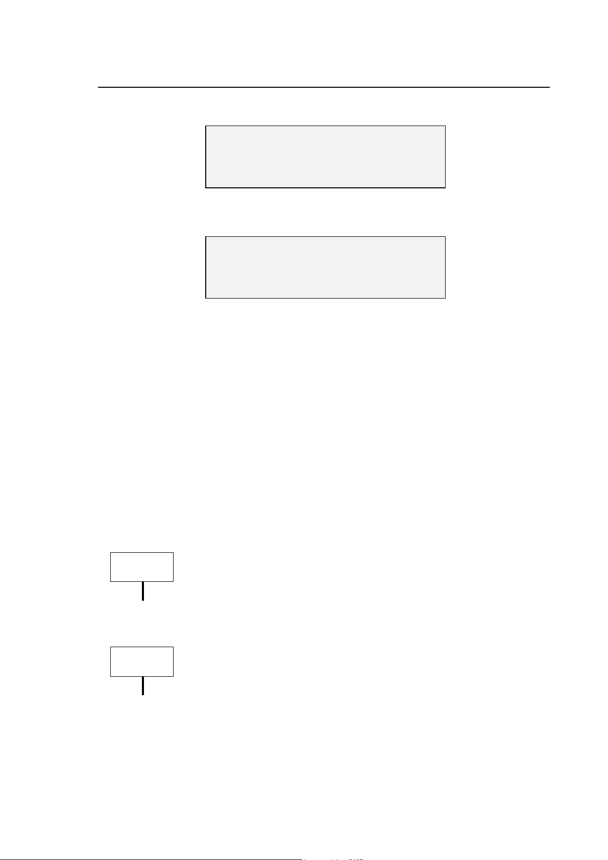
“OSAI SECURITY” user interface
Once the program is activated the video page is visualised from which it is possible to choose the
type of function to execute. If the CN is in the Setup mode all the functions are enabled, if the CN is
in Emergency mode only the Option functions and the Fixup will be enabled.
To enable all the functions you must follow the procedure that is explained previously.
The main screen is as follows :
The screen is divided in three principal panels:
• The panel on the left visualises the data of the connected control.
• The panel on the right visualises the data and the keys that concern the operation selected by
the user
• The lower panel visualises the control messages when an operation is activated and a
progression bar is visualised during the elaboration time
The commands are activated by a drop down menu, through the softkey bar at the bottom and the
activation bar on the right. When the user selects an operation all these commands are not
enabled.
10 Series CNC Software Installation Manual (16) 2-7

Capitolo 2
Osai Security
“OSAI Security” can visualise and manage:
• Information on installed software Fixup
• Information on enabled options on CNC
• The access authorisations
• passwords for all levels
• the product Authorization Key
it is also possible:
• to install the software, the options and the fixup of the CNC
• to backup the existing files on the CNC
• to restore files on the CNC
• to modify the CNC’s name in the net
2-8 10 Series CNC Software Installation Manual (16)

Capitolo 2
Osai Security
Information on Fixup
For Fixup we intend all the corrections and/or the new performances that have been done on the
basic release of the CNC. Each Fixup is identified by a code related to the product and the version.
The Fixups of the basic release E69 are cumulative, that is to say that a new version includes all
the corrections and/or new performances and the previous ones
When you install a release the associated Fixup level is 0.
The application visualises this information in the right panel.
A list contains the fixup versions installed on CNC. If you select an element of this list the details
are visualised in the window on the side.
10 Series CNC Software Installation Manual (16) 2-9

Capitolo 2
Osai Security
Information on Options
The options are system functionalities which are enabled by the introduction of the Product
Authorisation Keys (PAK).
The options that are identified by a code which starts with letter “E” (Exx) are not part of the basic
release E69 and must be installed on the CNC after having installed the basis software identified
by the code E69
The options which are identified with a code that starts with the letter “A” (Axx) indicate the
functionalities that must not be installed but simply enabled through PAK.
The application visualises the information on the enabled/disabled options on the right panel.
There is also a list with all the options enabled by the PAK. There is a second list with all the codes
of the options installed on the CNC; selecting an element from this list the details of the option are
visualised in window on the side.
2-10 10 Series CNC Software Installation Manual (16)

Capitolo 2
Osai Security
Security protection levels
Security protection levels can be changed only when the CNC connected is in SETUP modality,
but they can be viewed in other modalities too.
These protection levels allow or don’t allow the use of some system instruments for the machine
tuning.
There are 7 protection levels (from level 0 higher priority to level 6 lower priority):
LEVEL USER FUNCTIONS
0 Osai R&D reserved
1 Osai R&D reserved
2 Osai SERVICE technical assistence
3 APPLICATION/OEM application development and integration
4 END USER option installation
5 END USER TEC technological program development, tool
management
6 OPERATOR machine tool use
To change the protection level in use, with higher priority one it is necessary to digit, if decided, the
protection password and press the key [Apply]; it is not necessary to digit any password when
lower priority levels are activated. The maximum length of the password string is 20 characters.
After the installation of the basic release E69 the default protection level is 6, and the passwords
for the levels 3, 4 and 5 are not set.
To modify the protection levels you must double click on the left button of the mouse on the
element of the list or press the space bar after having selected it.
10 Series CNC Software Installation Manual (16) 2-11

Capitolo 2
Osai Security
The protection levels modification follows these rules (a part from level 0 which cannot be
modified):
1. it is possible to modify just the successive levels,
2. it is possible to modify a protection level only if the previous one (higher priority) allows it.
3. If it is not possible to modify a certain level this will automatically be extended to less priority
levels.
The modifications will be activated on the control only after having clicked
WARNING
[Apply]; it is possible to restore the previous situation clicking [Restore] that
reads the last data that has been saved on the control.
Name of the CN in the net
The field “Assign net name” allows to modify the name of CNC on the net.
The new name will be used by the CNC only when you have bootstrapped
WARNING
the CNC.
2-12 10 Series CNC Software Installation Manual (16)

Osai Security
Password
It is possible to modify the password only when the connected CNC is in SETUP modality.
Capitolo 2
It is possible to control the activation of the protection levels through a password; the definition of
the passwords at different levels generates a level protection mechanism that a user of a superior
level can exploit to block access to the users of a lower level.
To insert a password on a level that didn’t have one, leave the field empty of the old password and
digit the same characters on the fields new password and password confirmation and press
[Apply].
To take away the password on a level that had it, digit the characters in the field of the old
password and leave the fields new password and confirm password empty and press [Apply].
To modify a password on a level that already had it, digit the right characters in the three fields old
password, new password and confirm password and press [Apply].
The maximum length of the password is 20 characters.
10 Series CNC Software Installation Manual (16) 2-13
Capitolo 2
Osai Security
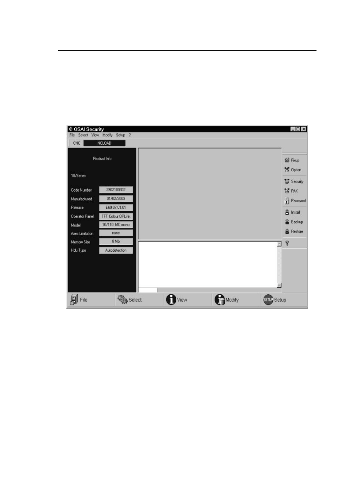
Product Authorization Key
The modification of the Product Authorization Key (PAK) is possibile only when the connected
CNC is in SETUP mode.
If the introduction of the PAK takes place correctly the system enables the functionalities or
installation of the optional component.
The Product Authorization Key is composed of three alfanumerical strings each of which has 20
characters.
2-14 10 Series CNC Software Installation Manual (16)
Capitolo 2
Osai Security
SETUP FUNCTIONALITY
The Setup allows to install, save and restore the system software of the CNC and user’s data.
The Security has also got an import function of backups generated with the “Remote Setup”
(option E103 obsolete and substituted by this application). This function transforms the backup in
the new format using “OSAI Security “ to guarantee the compatibility.
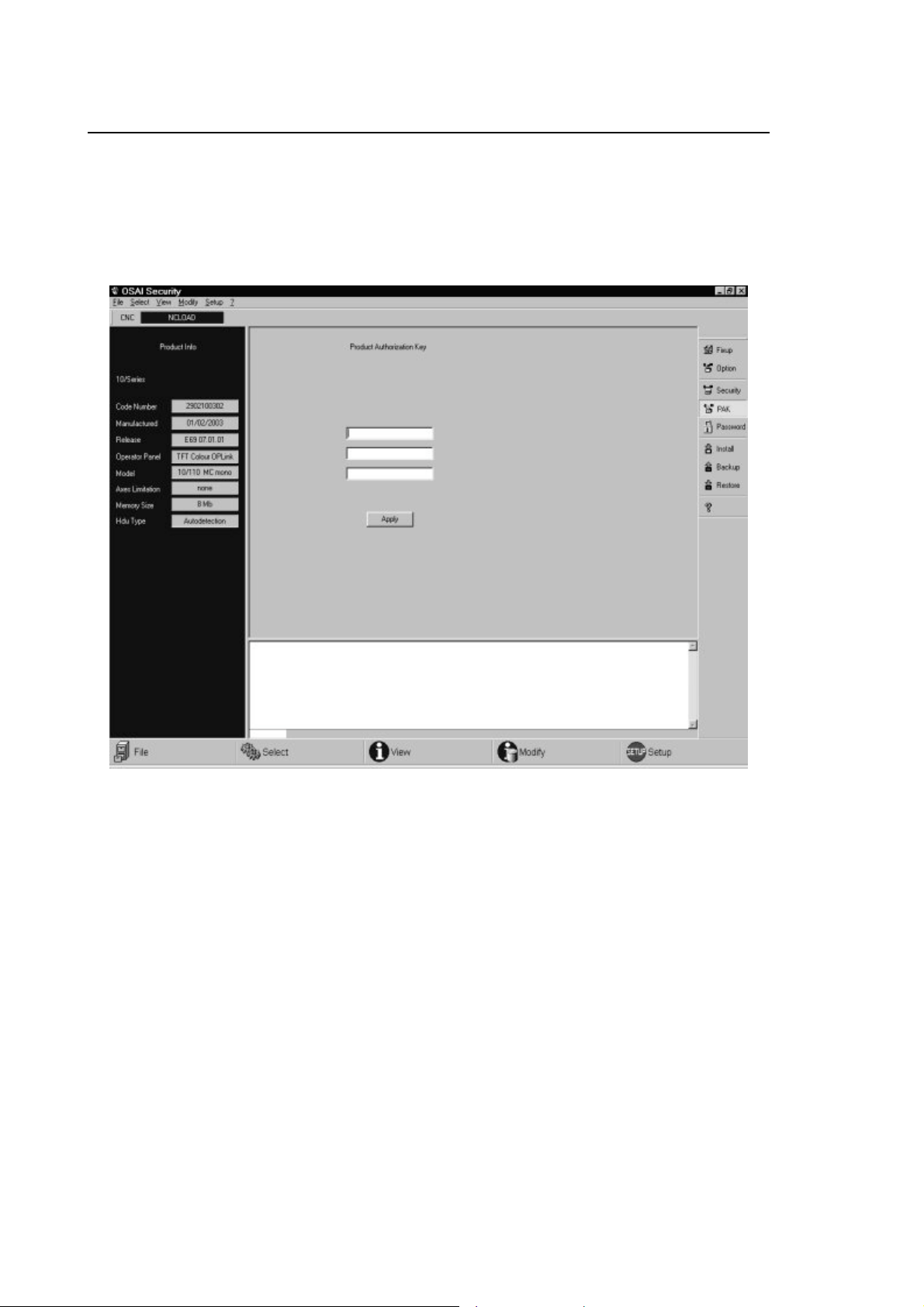
Installation on a new control
One of the Setup functionalities allows to install the software release of the CNC on a control (that
has Ethernet connection) just delivered by OSAI. Once the control is on it is available in local net
with NCLOAD name.
The following operations are the one that have to be executed:
1) Connect in Ethernet the numerical control and the system with the WinNBI
2) Start the BootController and select with the softkey [Select] [CNC] the name NCLOAD and
request the boot SETUP modality.
3) Switch on the numeric control and wait for BootController to connect with it.
10 Series CNC Software Installation Manual (16) 2-15

Capitolo 2
Osai Security
4) Launch the application “OSAI Security”
5) Select the modality [INSTALL]
6) Select, using [Browse…] a file that has extension “.inf” associated to a release
7) Select a the option New Control
8) Press the key [Start].
The installation procedure will label and update the parts of System, OEM and End User.
The operations which are been carried out are shown in a notification window where a progress
bar shows the state of the single operations when these need a certain amount of time to end.
2-16 10 Series CNC Software Installation Manual (16)

Capitolo 2
Osai Security
Release update
The setup can be used to update the release on a control (with hardware Ethernet connection) that
works correctly and is operative.
The sequence of operations are the following:
1) Launch BootController and select with the softkey [Select] [CNC] the given name to the
numerical control (visible in boot phase on the display of the CNC) and force the boot
[SETUP] modality.
2) Switch on the numerical control and wait for BootController to connect with it
3) Launch “OSAI Security”
4) Select [INSTALL] modality
Select through the key Browse a file with “.inf” extension associated to a release
Select the option release update
Press the key [Start].
Once the installation procedure is activated it will label and update the system and OEM partitions.
If it is not possible to connect to the control with the BootController (damage to HDU unit or loss of
data in the partitions) you can try to restore the functionalities (see paragraphs “Hard Disk” just
installed and “Impossibility to connect the CNC though net”.
The operations that have been carried out are visualised in the notify window where a progress bar
allows to control the state of the single operations when these need a long time to finish.
10 Series CNC Software Installation Manual (16) 2-17
Capitolo 2
Osai Security
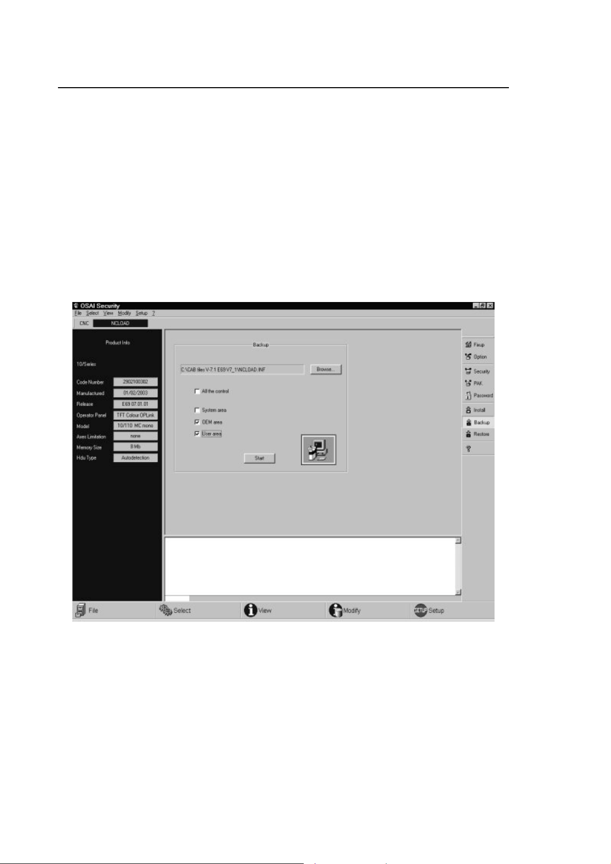
Backup
This operation concerns partition D, E, F of the numerical control. The files contained in these
partitions are memorised in a file which is specified by the user with extension “.inf”. Identifing
infomation is also saved here, like the date of the backup and the partition labels.
The saving operation (Backup) allows to choose between 4 types of options, which can or not be
summed by the user:
1. Saving of all the control (disables the other options)
2. Saving of the system areas
3. Saving of the user’s area
4. Saving of OEM area
2-18 10 Series CNC Software Installation Manual (16)

Capitolo 2
Osai Security
Restore
The restore operation allows to restore the content of the system area, OEM and End User of the
CNC saved previously with the Backup operation. The files saved with the old option ”Remote
Setup” can be charged after they have been converted in the new format using the option “Import”
(see next paragraph).
The operation allows to choose the three enabled areas, specifying through the key [Browse] the
name of the file with “.inf” extension where you can find the data. To start the operation press
[Start]. At the bottom there will be a window with the execution messages of the program and a
status bar that indicates the execution time.
10 Series CNC Software Installation Manual (16) 2-19
Capitolo 2
Osai Security
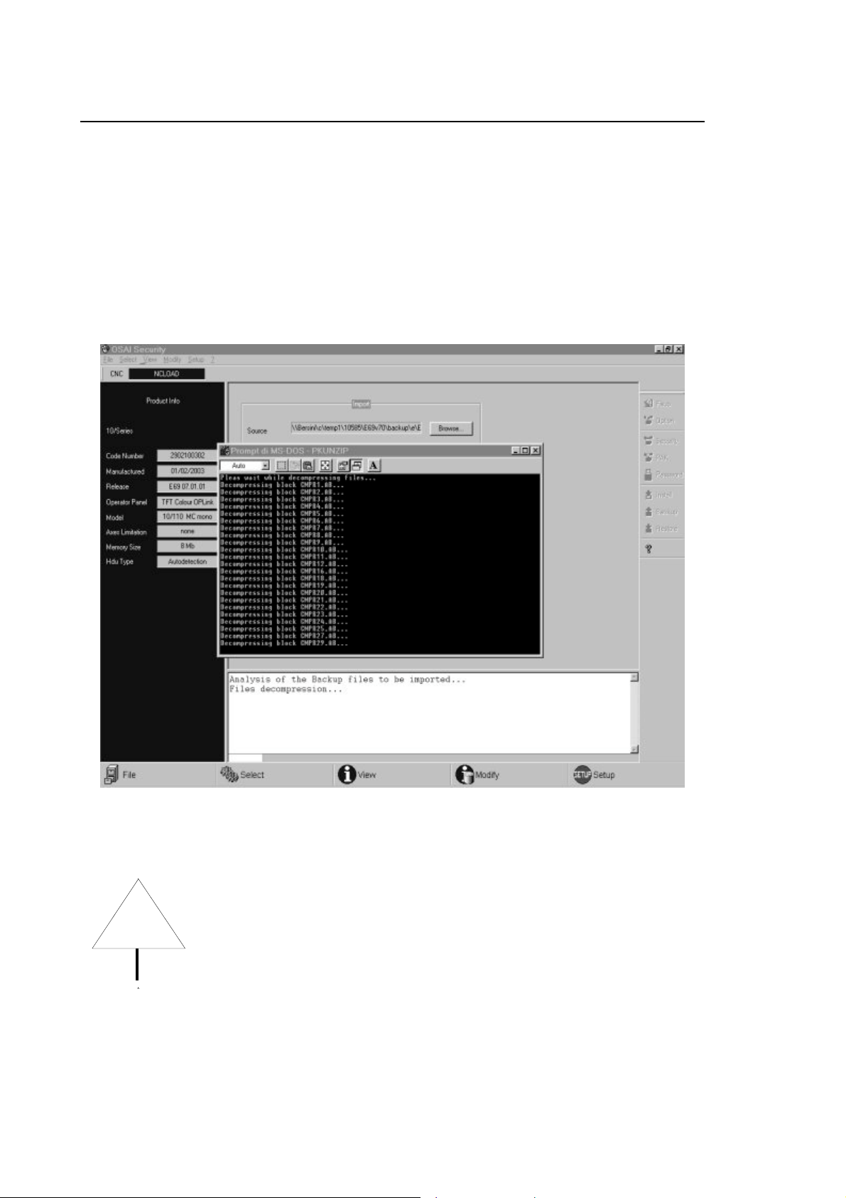
Import files
The operation “import” allows to tranform the backup files generated with the tool “Remote Setup”
in a format which is compatible with “OSAI Security”.
The operation can only be activated with the toolbar at the bottom, choosing the key [Setup] and
from the menù [Import]; at this point a window will open where you will have to specify the name of
the file that must be converted with extension “.dat” and the output file name that has to be
generated with extension “.inf”.
In the lower window you will find the execution messages of the operation.
Only files concerning partition E and F (name used by “Remote Setup”) that
WARNING
correspond to partitions OEM and End User will be copied in the output
files.
END OF CHAPTER
2-20 10 Series CNC Software Installation Manual (16)

Chapter 3
MODIFICATIONS AND IMPROVEMENTS INTRODUCED WITH
RELEASE E69 V7.5
FOREWORD
This chapter contains information about the new software features and improvements introduced
on 10 Series systems with release 7.5.
We recommend that you read this chapter carefully to make sure that no problems arise when the
system is upgraded to the new release.
NOTE:
Appendix D of this manual provides a description of the software features and improvements
introduced with the previous releases of the product, starting from Rel. 5.0.
10/365 and 10/385 systems are NOT compatible with Release 6.0 and
WARNING
WARNING
In release 7.5, changes have been made to the following environments:
• SYSTEM
• AMP
• PLUS, WINPLUS, I/O
higher.
Systems 10/310 are NOT compatible with release 7.0 and higher.
• PROCESS, AXES
These changes are described in detail on the pages that follow.
10 Series CNC Software Installation Manual (17) 3-1

Chapter 3
Modifications and Improvements Introduced with Release 7.5
Changes made to the SYSTEM environment
• New OS8516 board
The management software for a new board, OS 8516, has been added. It is available in various
versions and it is able to manage two Mechatrolink channels, an encoder channel, field bus I/Os
and analog I/Os.
• Extension of Continuous Laser Digitizing option
Now it is possible to use either the OS8531 board or the OS8532 board with OS8521/3 for
“laser digitisation”.
• Extension of D.S.I. digital drives management
The management software for Indramat D.S.I. digital drives has been added.
• New Canopen RIO modules
The management software for new Canopen RIO modules has been added: 8 digital 2A
Outputs and 4 digital Relay Outputs.
• New Os-Wire parameters
The management software for two new OS-Wire axis parameters has been added: parameter
98 to define the “blind zone” and a “volatile” parameter, 500, defining “Current limitation”.
“Volatile” parameters are not saved in a parameter file and are initialised with a default value at
each power-up. Now these parameters can be read/written only from the Plus/WinPlus
environment (Functions AX_FWR, AX_FWW) and require the new versions of the firmware for
drives E110 V2.0 and WinNBI V2.4.
• Spanish Help menu completed
The Help menu in Spanish (E99) has now been completed with the Spanish translation of the
softkeys and data entry modalities, and is in line with other Help menus in French and German.
3-2 10 Series CNC Software Installation Manual (17)

Chapter 3
Modifications and Improvements Introduced with Release 7.5
Changes made to the AMP environment
• Characterisation of new D.S.I. board
The HARDWARE CONFIGURATION section now includes the characterisation of a new board,
OS 8512, whose management software will be made available with an E69 V7.5 Problem Fix.
• Os-Wire axes servo loop clock
For OS-Wire systems, it is now possible to configure the servo loop clock as a multiple of that of
the system. In the earlier release, these values had to be the same.
• Handwheel programmability
For all systems, in the management of the electronic handwheel, the control over the maximum
number of programmable transducers has been eliminated (value set from PAK). In actual
practice, when the handwheel is activated, the handwheel associated with it is no longer
counted for purposes of the aforementioned control. The logic functions affected by this change
are: HPG_ON, HPG_OFF.
• New ”homing” modalities for D.S.I. axes
A new homing modality has been introduced for D.S.I. axes (HOMING TYPE field in axis
characterisation). It is equivalent to modality 3 (automatic homing executed by the drive) save
for axis repositioning on NULL OFFSET, a step which is not performed with this new modality. It
can also be used for point-by-point axes.
IMPORTANT
Keep in mind that AMP files cannot be transferred to a system where the
version of the release installed is earlier than that of the system the AMP
files originate from.
10 Series CNC Software Installation Manual (17) 3-3

Chapter 3
Modifications and Improvements Introduced with Release 7.5
Changes made to the PLUS, WINPLUS, I/O environment
• New GetTaskSlotn function
New WinPlus GetTaskSlotn function has been introduced to be able to determine the current
task and the slot in which it is running.
• New AX_RTFBCK function
Now it is possible to monitor the “internal” variables of the OS3 drive. This can be done thanks
to the new function WinPlus AX_RTFBCK. It requires the new versions of the firmware for
drives E110 V2.0 and WinPlus V2.10.2.
• New filters for GTS,GTA,SPG
New filter routines have been introduced in both the PLUS and the WinPlus environment; they
are activated on the ACTIVATE/DEACTIVATE Part Program ($N_SPGFUN), axis migration
($n_GTAFUN) and spindle sharing ($n_GTSFUN).
• New functions for CANopen devices managed by intelligent module
New functions CAN_INIT, GET_EMCY_INFO, NMT_CMD, SYNC_CMD, READ_SDO_CMD,
WRITE_SDO_CMD and CAN_BOARD_CMD have been added for the management from
WinPLUS of CANopen devices connected to the “intelligent” CANopen module.
• New function MOVBYTE
Limited to the WinPLUS environment, a new function MOVBYTE has been added for buffer
copy generation.
• New functions PUTUSED, GETUSEC and PUTUSEC
New functions have been added to the WinPLUS library: PUTUSED for writing double type
process variables, GETUSEC and PUTUSEC for reading/writing char type process variables.
• New event task EventTaskFIN
A new event task has been introduced for the management of “Fast Inputs”.
• Extension of ANAIN function block
The ANAIN function block has been extended to read the analog channels in the new board
(OS8516).
• Extension of $AX_SETZ function block
Function block $AX_SETZ has been extended so that it can work on Mechatrolink digital axes.
• Change to Tool Magazine error codes
Now, the error codes returned by the WinPlus functions for the management of tool magazines
(Tool Magazine option) are the same as those of the corresponding F.B.s in the PLUS
environment.
PLUS environment: after installing the release it is indispensable to
IMPORTANT
regenerate the “C“ code and to recompile the machine logic for the Plus
environment (PLUSGEN softkey)
WinPlus environment: after the installation of this release, you must
IMPORTANT
recompile the machine logic with the new version of WinPlus C08 V2.10.2
by making the appropriate changes to the <firmware version> parameter.
Logics compiled with earlier versions will not work !
3-4 10 Series CNC Software Installation Manual (17)

Chapter 3
Modifications and Improvements Introduced with Release 7.5
Changes made to the PROCESS, AXES environment
• Spindle sharing by several processes
Now, with the new triliteral GTS, several processes can share the same spindle. The triliteral
enables each process to release its spindle and change its status or acquire a new spindle.
• Extension of the UPR function
A new type of UPR 5 has been implemented: it returns in the E variables the physical or virtual
coordinates of rotary axes relative to an active UPR.
The software for the management of the origins on the rotary axes has also been introduced.
These origins must be entered in the triliteral itself.
• HSM: new management for ijk versors
A new management software for ijk versors in the HSM environment has been implemented.
This is based on the punctual conversion of such versors into the corresponding coordinates of
the rotary axes and the ensuing determination of the relative splines. This software remedies
the problems arising from the oscillation of rotary axes when moving to critical (indeterminate)
positions.
IMPORTANT
Keep in mind that in this release, and after the introduction of Problem Fix 2
of E69 V7.4, the algorithms associated with function UPR have been modified
to solve a number of problems encountered with said function.
As a result, axis movements arising from the virtualisation may differ from
those generated by the earlier algorithms (releases lower than 7.4.2).
To keep the earlier algorithms working, the new user variable must be set as
!R73MODE=1. Otherwise, if !R73MODE=0, or not defined, the new
algorithms will be applied. This user variable is read only in conjunction with
the programming of lower case UPR.
10 Series CNC Software Installation Manual (17) 3-5

Chapter 3
Modifications and Improvements Introduced with Release 7.5
END OF CHAPTER
3-6 10 Series CNC Software Installation Manual (17)

A
OPTIONS COMPATIBILITY TABLES
OPTIONS
ONLINE OPTIONS Sw rel.
Tool magazine management E41 7.5 YES YES
Appendix
10 MC Series
7.4 7.5
Manual digitizing E42 7.5 YES YES
DOS graphic interface E43 7.5 YES YES
DOS real time interface E58 7.5 YES YES
Electronic cam E59 7.5 YES YES
English help E70 7.5 NO YES
Italian help E71 7.5 NO YES
French help E78 7.5 NO YES
German help E77 7.5 NO YES
Spanish help E99 7.5 NO YES
Asset E73 7.5 YES YES
End user DOS E74 7.5 YES YES
Wood option E72 5.0.1c YES YES
Remote diagnostic E84 6.0.1 YES YES
Super Multi-process option E87 7.5 YES YES
Continuous Laser Digitizing E90 7.5 YES YES
Serial Mini DNC for Windows E94 6.0.1 YES YES
High speed interpolation E96 7.5 YES YES
Multi process E75 7.5 YES YES
CNC setup utility E97 6.0
7.4
BIOS utilities E104 7.1 YES YES
10 Series CNC Software Installation Manual (18) A-1
YES
YES
NO
YES

Appendix A
Options Compatibility Tables
BIOS utilities E109 1.0 YES YES
BIOS utilities E113 1.3 YES YES
CNC Init Disk E107 7.4
7.5
CNC Recovery Disk E108 7.4
7.5
OS3 Firmware E110 1.3
1.4
Motors Library E111 1.3
1.4
YES
NO
YES
NO
YES
YES
YES
YES
NO
YES
NO
YES
YES
YES
YES
YES
For additional information on the compatibility of E110, E69, C07, see the “OS3 Drive
Installation” Manual and the individual release issuing documents.
c When the option has been installed, it is indispensable to regenerate code “C“ and
recompile the DEF_WOOD default logic to achieve compatibility with the system release.
10 MC Series
7.4 7.5
OFFLINE OPTIONS Sw Rel.
Dicadig E35 5.3 YES YES
Lathe graphic editor E36 4.0 YES YES
Mill graphic editor E37 4.0 YES YES
Wood Editor E85 5.1 YES YES
Ethernet Mini Dnc Communication E66 6.0 YES YES
Remote Development Kit E88 7.5 NO YES
Remote Setup E103 6.1 NO NO
Path optimizer E106 2.2
2.3
WinNBI C07 2.4
2.4.3
WinPLUS C08 2.08
2.10
2.10.2
YES
YES
YES
YES
NO
YES
YES
YES
YES
YES
YES
NO
NO
YES
A-2 10 Series CNC Software Installation Manual (18)

Appendix A
Options Compatibility Tables
Mass storage size compatibility
Depending on the option selected, controls 10/110 and 10/510 Light can be equipped with different
mass storage devices: either Hard Disk modules or solid state “DOMs” (= Disk on Module).
The different versions provide different User Memory capacities, where by User memory is meant
the maximum capacity of user disk F:.
The size of these Modules changes as a function of the Software Release installed:
With Software Release 7.4 or higher, the options available for 10/510 LIGHT, and the respective
(approximate) E: and F: user disks capacities are as follows:
93000587B 510 LIGHT 15 MB USER PROGRAM MEM E: = 19 MByte, F: = 15 MByte
93000645F 510 LIGHT 40 MB USER PROGRAM MEM E: = 41 MByte, F: = 40 MByte
93000588W 510 LIGHT 2 GB USER PROGRAM MEM E: = 53 MByte, F: = 2 GByte
Control 10/110 LIGHT OS-WIRE, managed by Software Release 7.4 and higher, always has a 40
MBYTE user memory capacity and therefore, as above: E: = 41 MByte, F: = 40 MByte
In Software Release 7.3, (approximate) capacities were:
93000587B 510 LIGHT 19 MB USER PROGRAM MEM E: = 15 MByte, F: = 19 MByte
93000588W 510 LIGHT 2 GB USER PROGRAM MEM E: = 53 MByte, F: = 2 Gbyte
With Software Release 7.5 fix 4 or higher, the options available for 10/510 LIGHT, and the
respective (approximate) E: and F: user disks capacities are as follows:
93000587B 510 LIGHT 15 MB USER PROGRAM MEM E: = 19 MByte, F: = 15 MByte
93000645F 510 LIGHT 40 MB USER PROGRAM MEM E: = 43 MByte, F: = 40 Mbyte
93000664N 510 LIGHT 400 MB USER PROGRAM MEM E: = 64 MByte, F: = 400 MByte
93000665P 510 LIGHT 900 MB USER PROGRAM MEM E: = 64 MByte, F: = 900 MByte
93000666R 510 LIGHT 1.8GB USER PROGRAM MEM E: = 64 MByte, F: = 1,8 GByte
93000588W 510 LIGHT 2GB USER PROGRAM MEM HDU E: = 53 MByte, F: = 2 GByte
10 Series CNC Software Installation Manual (18) A-3

Appendix A
Options Compatibility Tables
END OF APPENDIX
A-4 10 Series CNC Software Installation Manual (18)

Appendix B
ERROR MESSAGES
ERROR MESSAGES LIST
This Appendix lists the error messages that may be displayed during system software installation.
For each message we suggest a recovery action.
MESSAGE FILE NOT FOUND
Internal software error. One of the utility support files is corrupt.
Contact the Technical Assistance Service.
BACKUP FILE NOT FOUND
Internal software error. back up binary files corrupt.
Contact the Technical Assistance Service.
INSUFFICIENT MEMORY
Not enough memory to copy the working areas used by the utility.
Contact the Technical Assistance Service.
BACKUP DATA CORRUPT
The backup to be installed is corrupt.
Contact the Technical Assistance Service.
INSTALLATION DISK UNDEFINED
If this error occurs when the initialisation process is launched, it means that the HD has not been
partitioned: use the E107 option. If the error persists, 0 occurs in a case other than the one
described. Contact the Technical Assistance Service.
WRONG DISKETTE
You are trying to install a release back up through the security utility.
Restart the system using the first back up floppy.
THE FLOPPY INSERTED IS NOT THE FIRST
The diskette from which installation has been launched is not the first back up diskette.
Restart the system inserting the first back up diskette (i.e. the one whose label ends by 01).
10 Series CNC Software Installation Manual (16) B-1

Appendix B
Error Messages
ASCII FILE NOT FOUND
Internal software error. One of the utility support files is missing.
Contact the Technical Assistance Service.
OPTION NOT ALLOWED: CHECK SECURITY
Installation of this option has not been authorized by the security utility.
Start the system in emergency mode, write the Product Authorization Keys associated to the option
and resume installation with the INSTALL softkey.
STOP INSTALL: HDU TOO SMALL!
This message is displayed when trying to install release 5.0 on a hard disk smaller than 80 Mbytes.
END OF APPENDIX
B-2 10 Series CNC Software Installation Manual (16)

Appendix C
INSTRUCTIONS FOR CNC SETUP
Three types of integrated Operator Panels can be connected to Series 10 controls:
• OPLink Operator Panel
• BLink Operator Panel
• WinLink Operator Panel
The 3 models of Operator Panel are available with a TFT color monitor, but each of them has
different characteristics, as shown in the following table:
the version with integrated Operator
Console (OPLink) includes:
the basic version (BLink) includes:
the version with integrated PC (WinLink)
includes:
For those differences each system has to be properly configured according to the Operator Panel
used.
Each 10 Series Control is prepared by OSAI to be connected to the type of Operator Panel
specified in the CNC SETUP module attached to each control.
The aim of this chapter is to describe the operations to be performed to modify this configuration
when required in order to avoid system damage and failures.
− Monitor 10.4"
− the Operator Console
− 7 softkey
− 3 keys for CYCLE START, HOLD and RESET;
− 6 function keys with LED which the manufacturer
can use for customisation through the machine
logic
− Monitor 10.4"
− 7 softkey
− 12.1” monitor
− “yellow” key
− 13 function keys available for the PC environment
For 10/585 and 10/565 systems the utility provided with the E97 option, called the “CNC Setup
Utility”, is to be used.
10 Series CNC Software Installation Manual (16) C-1
Appendix C
Instructions for CNC Setup
SETUP UTILITY
The SETUP utility contained in the “E97 CNC Setup Utility” floppy disk makes it possible to
configure the type of Operator Panel connected to the control.
Insert the E97 bootstrap disk in the floppy disk drive before turning on the CNC: during the
bootstrap phase a window similar to the following will appear on the display.
The following screen appears after the bootstrap phase has been completed:
BIOS SETUP ver.x.y SYSTEM 10-5x5
LCD OPERATOR PANEL
MESSAGE
F5 Abort Setup F6 Save and exit Setup F10 Change item
Where:
LCD OPERATOR PANEL: area containing the Operator Panel version
MESSAGE: area reserved for the messages from the utility
[F5]: to exit from the SETUP without saving the data set on the display and
therefore, without changing the system configuration. After you exit
the system will be rebooted automatically.
[F6]: to exit from the SETUP saving the selected Operator Panel version in
the system configuration. When you exit from the utility, the system
will be rebooted automatically.
[F10]: to select Operator Panel model in the “LCD OPERATOR PANEL”
area.
C-2 10 Series CNC Software Installation Manual (16)

Appendix C
Instructions for CNC Setup
When started, the SETUP utility reads the system’s Hardware Key (PAK) on which the
configuration data is stored.
The currently configured Operator Panel model is displayed in the “LCD OPERATOR PANEL”
area and the new model may be selected by pressing the [F10] key. The [F5] and [F6] keys may
be used to confirm or cancel the selection of the model and exit from the SETUP.
The error messages that can appear in the “MESSAGE” area, are the following:
1. “ERROR ON READ HW_KEY” (ERROR)
2. “ERROR ON WRITE HW_KEY” (ERROR)
3. “HW_KEY INCONGRUENT” (ERROR)
The messages 1 and 2 are referred to general errors during Hardware Key read/write operations:
In this case, please contact the OSAI engineering service.
Message 3 is displayed when it is not possible to read the Hardware Key (PAK) or when the data
contained are corrupted.
To restore the PAK it is necessary to install the release: insert the first disk of the E69 System
Software in the floppy disk drive and switch the system off and then on again and, when the
Control bootstraps, install the release following the instructions given in the Software Installation
Manual.
During the software release download, if the Hardware Key (PAK) is not correctly found or
recognised, the installation program will ask for the PAK.
The Hardware Key is ALWAYS provided in a specific module attached to the control.
If another error occurs after the release has been installed, contact the OSAI Technical Assistance
service.
10 Series CNC Software Installation Manual (16) C-3

Appendix C
Instructions for CNC Setup
BIOS UTILITIES (E104, E109, E113, E114)
Bios Utilities is an option used to load the Bios in 10/100, 10/110, 10/510, 10/565, 10/585, 12.1"
and 10.4" Operator Panel WinLink, 10/510 WinLink systems.
It consists of four sets of floppy disks: E104 (7 disks), E109 (3 disks), E113 (1 disk) and E114 (1
disk), whose labels and contents are described below:
E104
E104 Bios utilities (for CNC 10/110, 10/565, 10/585 10.4”) disk 1/7
Bios for CNC systems specified
with 10.4” TFT or 10.4” WinLink
Operator Panel
E104 Bios utilities (for CNC 10/510, 10/100 10.4”) disk 2/7
Bios for CNC 10/510 10/100
system with 10.4” TFT
E104 Bios utilities (for CNC 10/510 WinLink 12.1” CPU 430) disk 3/7
Bios for 10/510 WinLink
system, CNC side, with 12.1”
TFT and CPU PC-430 G2
E104 Bios utilities (for PC 10/510 WinLink 12.1” CPU 1560) disk 4/7
Bios for 10/510 WinLink
system, PC side, with 12.1”
TFT and CPU PROX-1560
E104 Bios utilities (for CNC 10/565, 10/585 12.1” ) disk 5/7
Bios for CNC systems
specified, connected to WinLink
Operator Panel with 12.1” TFT
E104 Bios utilities (for PC WinLink Operator Panel 12.1” ) disk 6/7
Bios for WinLink Operator Panel
system with 12.1” TFT
E104 Bios utilities (for PC WinLink Operator Panel 10.4” ) disk 7/7
Bios for WinLink Operator Panel
system with 10.4” TFT
C-4 10 Series CNC Software Installation Manual (16)

E109
E109 Bios utilities (for CNC 10/510i WinLink 12.1” CPU 1630) disk 1/3
Bios for system 10/510i
WinLink, CNC side, with TFT
12.1” and PROX-1630 CPU
E109 Bios utilities (for PC 10/510i WinLink 12.1” CPU 1630) disk 2/3
Bios for system 10/510i
WinLink, PC side, with TFT
12.1” and PROX-1630 CPU
E109 Bios utilities (for CNC 10/510i 10.4” CPU 1630) disk 3/3
Bios for CNC 10/510i system
with 10.4” TFT and PROX1630 CPU.
E113
Appendix C
Instructions for CNC Setup
E113 Bios for 10/510s and 10/110 10.4” CPU 1260 CNC systems disk 1/1
Bios for CNC 10/510s light
system with 10.4” TFT and
PROX-1260 CPU.
E114
E114 Bios for WinMedia TFT 15” CPU Prox 3655 disk 1/1
Bios for the WinMedia system
with 15” TFT and PROX-3655
CPU
As a rule, Series 10 systems are initialised upon being launched for the first time during the
production testing stage: hence the Bios loading process becomes necessary only if the CPU
board is replaced or Bios data are deteriorated, which is a rather unlikely occurrence.
NOTE:
When the Bios is installed, the relative parameters (other than default parameters) are also loaded
(see systems 10/110 CNC, 10/100 CNC, 10/510 CNC). Access to the Bios Setup for such
systems, no longer necessary, is protected by a password.
WARNING
If the BIOS upgrade procedure is interrupted while the Flash memory in
which the BIOS resides is being overwritten (e.g. by removing the floppy disk
or cutting out the power to the CNC) the CPU of the CNC may be damaged.
Hence, it is essential to wait for the end of the procedure before pulling out
the floppy disk from the relative driver. The end of the procedure is notified by
a visual and an audible signal, as described in greater detail in the following
pages of this document.
10 Series CNC Software Installation Manual (16) C-5

Appendix C
Instructions for CNC Setup
E104
Bios loading procedure for 10/565,10/585 CNC systems with 10.4" tft
operator panel or 10.4” tft operator panel WinLink
The Bios utilities supplied with floppy disk E 104 v 7.1 disk 1/7 lets you re-load the Bios if the CPU
has been replaced or the Flash memory of the CPU has been damaged.
To activate this function all you have to do is introduce the E104 v 7.1 disk 1/7 floppy disk into the
floppy disk driver connected to the CNC and turn on the control. Make sure that disk reading
starts, as indicated by the lighting up of the LED on the floppy disk driver.
Wait for the end of the loading process, as indicated by a message on screen and the switching off
of the LED on the driver, then turn off the system, remove the floppy disk from the driver and
restart the system.
While the Bios is being loaded, the TFT may remain without information, but this does not preclude
the correct loading of the Bios. In this case, we recommend that you wait ca three minutes of the
switching off of the floppy driver LED before turning off the CNC.
Bios loading procedure for 10/110 CNC systems
The Bios utilities supplied with floppy disk E 104 v.7.1 disk 1/7 lets you re-load the Bios if the CPU
has been replaced or the Flash memory of the CPU has been damaged.
To activate this function all you have to do is introduce the E104 v 7.1 disk 1/7 floppy disk into the
floppy disk driver and turn on the control. Make sure that disk reading starts, as indicated by the
lighting up of a LED on the floppy disk driver.
Wait for the end of the loading process, as indicated by a message on screen, the switching off of
the LED on the driver and an audible signal. Turn off the system, remove the floppy disk from the
driver and restart the system.
While the Bios is being loaded, the TFT may remain without information, but this does not preclude
the correct loading of the Bios.
Bios loading procedure for 10/510, 10/100 10.4" CNC systems
The Bios utilities supplied with floppy disk E 104 v7.1 disk 2/7 lets you re-load the Bios if the CPU
has been replaced or the Flash memory of the CPU has been damaged.
To activate this function all you have to do is introduce the E104 v7.1 disk 2/7 floppy disk into the
floppy disk driver and turn on the control. Make sure that disk reading starts, as indicated by the
lighting up of the LED on the floppy disk driver.
Wait for the end of the loading process, as indicated by a message on screen, the switching off of
the LED on the driver and an audible signal. Turn off the system, remove the floppy disk from the
driver and restart the system.
While the Bios is being loaded, the TFT may remain without information, but this does not preclude
the correct loading of the Bios.
C-6 10 Series CNC Software Installation Manual (16)

Appendix C
Instructions for CNC Setup
Bios loading procedure for 10/510 WinLink 12.1" systems, CNC side
The Bios utilities supplied with floppy disk E 104 v7.1 disk 3/7 lets you re-load the Bios if the CPU
has been replaced or the Flash memory of the CPU has been damaged.
To activate this function proceed as follows:
• Introduce the E 104 v7.1 disk 3/7 floppy disk into the floppy disk driver, CNC side.
• Turn on the control, both the CNC and the PC.
• Press the yellow key to recall the CNC environment (yellow key LED ON).
• Make sure that disk reading starts, as indicated by the lighting up of the LED on the floppy disk
driver, CNC side.
• Wait for the end of the loading process, as indicated by a message on screen, the switching off
of the LED on the floppy disk driver, and an audible signal. Turn off the system, remove the
floppy disk from the floppy disk driver and restart the system.
While the Bios is being loaded, the TFT may remain without information, but this does not preclude
the correct loading of the Bios.
Bios loading procedure for 10/510 WinLink 12.1" systems, PC side
The Bios utilities supplied with floppy disk E 104 v7.1 disk 4/7 lets you re-load the Bios if the CPU
has been replaced or the Flash memory of the CPU has been damaged.
To activate this function, proceed as follows:
• Introduce the E 104 v7.1 disk 4/7 into the floppy disk driver, PC side.
• Turn on the control, both the CNC and the PC.
• Make sure you are in the PC environment (yellow key LED OFF).
• Make sure that disk reading starts, as indicated by the lighting up of the LED on the floppy disk
driver, PC side.
• Wait for the end of the loading process, as indicated by a message on screen, the switching off
of the LED on the floppy disk driver, and an audible signal. Turn off the system, remove the
floppy disk from the floppy disk driver and restart the system.
While the Bios is being loaded, the TFT may remain without information, but this does not preclude
the correct loading of the Bios.
NOTE:
In 10/510 WinLink systems, the two Bios loading processes can be performed simultaneously.
Bios loading procedure for 10/565, 10/585 CNC systems with WinLink 12.1"
tft operator panel
The Bios utilities supplied with floppy disk E 104 v7.1 disk 5/7 lets you re-load the Bios if the CPU
has been replaced or the Flash memory of the CPU has been damaged.
10 Series CNC Software Installation Manual (16) C-7

Appendix C
Instructions for CNC Setup
To activate this function, proceed as follows:
• Introduce the E104 v7.1 disk 5/7 floppy disk into the floppy disk driver connected to the CNC.
• Turn on both the CNC and WinLink.
• Press the yellow key to recall the CNC environment (yellow key LED ON).
• Make sure that disk reading starts, as indicated by the lighting up of the LED on the floppy disk
driver connected to the CNC.
• Wait for the end of the loading process, as indicated by a message on screen, the switching off
of the LED on the floppy disk driver, and an audible signal. Turn off the system, remove the
floppy disk from the floppy disk driver and restart the system.
While the Bios is being loaded, the TFT may remain without information, but this does not preclude
the correct loading of the Bios. In this case, we recommend that you wait ca three minutes of the
switching off of the floppy driver LED before turning off the CNC.
Bios loading procedure for 12.1" tft operator panel WinLink systems
The Bios utilities supplied with floppy disk E 104 v 7.1 disk 6/7 lets you re-load the Bios if the CPU
has been replaced or the Flash memory of the CPU has been damaged.
To activate this function, proceed as follows:
• Introduce the E104 v7.1 disk 6/7 floppy disk into the floppy disk driver on WinLink.
• Turn on WinLink.
• Make sure you are in the PC environment (yellow key LED OFF).
• Make sure that disk reading starts, as indicated by the lighting up of the LED on the floppy disk
driver on WinLink.
• Wait for the end of the loading process, as indicated by a message on screen, the switching off
of the LED on the floppy disk driver, and an audible signal. Turn off the system, remove the
floppy disk from the floppy disk driver and restart the system.
While the Bios is being loaded, the TFT may remain without information, but this does not preclude
the correct loading of the Bios.
C-8 10 Series CNC Software Installation Manual (16)

Appendix C
Instructions for CNC Setup
Bios loading procedure for 10.4" tft operator panel WinLink systems
The Bios utilities supplied with floppy disk E 104 v 7.1 disk 7/7 lets you re-load the Bios if the CPU
has been replaced or the Flash memory of the CPU has been damaged.
To activate this function, proceed as follows:
• Introduce the E104 v7.1 disk 7/7 floppy disk into the floppy disk driver on WinLink.
• Turn on WinLink.
• Make sure you are in the PC environment (yellow key LED OFF)
• Make sure that disk reading starts, as indicated by the lighting up of the LED on the floppy disk
driver on WinLink.
• Wait for the end of the loading process, as indicated by a message on screen, the switching off
of the LED on the floppy disk driver, and an audible signal. Turn off the system, remove the
floppy disk from the floppy disk driver and restart the system.
While the Bios is being loaded, the TFT may remain without information, but this does not preclude
the correct loading of the Bios.
10 Series CNC Software Installation Manual (16) C-9

Appendix C
Instructions for CNC Setup
E109
Bios loading procedure for 10/510i WinLink 12.1" systems, CNC side
The Bios utilities supplied with floppy disk E 109 v1.0 disk 1/3 lets you re-load the Bios if the CPU
has been replaced or the Flash memory of the CPU has been damaged.
To activate this function proceed as follows:
• Introduce the E 109 v1.0 disk 1/3 floppy disk into the floppy disk driver, CNC side.
• Turn on the control, both the CNC and the PC.
• Press the yellow key to recall the CNC environment (yellow key LED ON).
• Make sure that disk reading starts, as indicated by the lighting up of the LED on the floppy disk
driver, CNC side.
• Wait for the end of the loading process, as indicated by a message on screen, the switching off
of the LED on the floppy disk driver, and an audible signal. Turn off the system, remove the
floppy disk from the floppy disk driver and restart the system.
While the Bios is being loaded, the TFT may remain without information, but this does not preclude
the correct loading of the Bios.
Bios loading procedure for 10/510i WinLink 12.1" systems, PC side
The Bios utilities supplied with floppy disk E 109 v1.0 disk 2/3 lets you re-load the Bios if the CPU
has been replaced or the Flash memory of the CPU has been damaged.
To activate this function, proceed as follows:
• Introduce the E 109 v1.0 disk 2/3 into the floppy disk driver, PC side.
• Turn on the control, both the CNC and the PC.
• Make sure you are in the PC environment (yellow key LED OFF).
• Make sure that disk reading starts, as indicated by the lighting up of the LED on the floppy disk
driver, PC side.
• Wait for the end of the loading process, as indicated by a message on screen, the switching off
of the LED on the floppy disk driver, and an audible signal. Turn off the system, remove the
floppy disk from the floppy disk driver and restart the system.
While the Bios is being loaded, the TFT may remain without information, but this does not preclude
the correct loading of the Bios.
C-10 10 Series CNC Software Installation Manual (16)

Appendix C
Instructions for CNC Setup
Bios loading procedure for 10/150i 10.4” CNC systems
The Bios utilities supplied with floppy disk E 109 v.1.0 disk 3/3 lets you re-load the Bios if the CPU
has been replaced or the Flash memory of the CPU has been damaged.
To activate this function all you have to do is introduce the E 109 v.1.0 disk 3/3 floppy disk into the
floppy disk driver and turn on the control. Make sure that disk reading starts, as indicated by the
lighting up of a LED on the floppy disk driver.
Wait for the end of the loading process, as indicated by a message on screen, the switching off of
the LED on the driver and an audible signal. Turn off the system, remove the floppy disk from the
driver and restart the system.
While the Bios is being loaded, the TFT may remain without information, but this does not preclude
the correct loading of the Bios.
10 Series CNC Software Installation Manual (16) C-11

Appendix C
Instructions for CNC Setup
E113
Bios loading procedure for 10/510s and 10/110 light 10.4” CNC systems
The Bios utilities supplied with floppy disk E 113 v.1.0 disk 1/1 lets you re-load the Bios if the CPU
has been replaced or the Flash memory of the CPU has been damaged.
To activate this function all you have to do is introduce the E 113 v.1.0 disk 1/1 floppy disk into the
floppy disk driver and turn on the control. Make sure that disk reading starts, as indicated by the
lighting up of a LED on the floppy disk driver.
Wait for the end of the loading process, as indicated by a message on screen, the switching off of
the LED on the driver and an audible signal. Turn off the system, remove the floppy disk from the
driver and restart the system.
While the Bios is being loaded, the TFT may remain without information, but this does not preclude
the correct loading of the Bios.
C-12 10 Series CNC Software Installation Manual (16)

Appendix C
Instructions for CNC Setup
E114
Loading the Bios for WinMedia systems with 15” TFT - ProX 3655 CPU
The Bios supplied with floppy disk E114 v1.0 makes it possible to reload the Bios if the CPU is
replaced or the Flash memory on the CPU is damaged.
To activate this function, proceed as follows:
• Introduce the floppy disk into the floppy disk drive on WinLink
• Start WinMedia
• Make sure that the system is reading the floppy disk, i.e., the floppy disk LED on WinLink lights
up
• Wait for the end of the loading process: when the Bios has been fully loaded, a message to
this effect appears on screen, the LED on the floppy disk drive goes out and an audible signal
is given out. Shut down the system, remove the floppy disk from the drive and restart the
system.
While the Bios is being loaded, the TFT may remain without information; this does not preclude the
correct loading of the Bios.
10 Series CNC Software Installation Manual (16) C-13

Appendix C
Instructions for CNC Setup
END OF APPENDIX
C-14 10 Series CNC Software Installation Manual (16)

Appendix D
SUMMARY OF MODIFICATIONS MADE WITH EARLIER RELEASES
This appendix contains information about all the functions and software enhancements introduced
with the product releases earlier than 7.5.
RELEASE 5.0
Release 5.0 brought changes to the following:
• SYSTEM
• AMP
• PLUS
• OPERATOR INTERFACE
• EMERGENCY START UP
• PERIPHERAL
• SERVO MONITOR
The changes in question are referred to in detail on the following pages.
IMPORTANT
Release V5.0 cannot be installed on systems equipped with either 40
Mbyte HDU or 4 Mbyte RAM.
Should a back up of the user area with release 3.x or 4.x be required, it is
necessary to use the first floppy disk of release 5.0 to be able to employ such
back up on the systems upgraded to release V5.0 (see chapter 1).
When release V5.0 is installed, Plus logic has to be activated since
DEFAULT4 logic is no longer activated by default.
10 Series CNC Software Installation Manual (17) D-1

Appendix D
Summary of Modifications Made with Earlier Releases
Changes to SYSTEM environment
• Upgrading with MS-DOS 6.22
The MS-DOS version was upgraded with following principles:
− editor for MS-DOS prompt is from version 3.30
− DEFRAG and SCANDISK programs are available for Front Panel Standard control only
− do not use any other MS-DOS 6.22 commands and utility programs not available in the
control should not be used.
• Partition extension for F: user programs
Size of F: partition was extended up to a max of 422 Mbyte according to the type of hard-disk
available on the system.
NOTE:
Above feature is available on all controls of new production.
Changes to AMP environment
• Number definition of configured processes
The GENERAL INFO section was modified to include a field for the configured processes
(1÷24). Such number is displayed in the data entry associated with SELECT PROCESS.
(Section: GENERAL INFO, field: Number of processes
• Field definition for memory searching
To enable/disable memory searching function, a field was added.
(Section: GENERAL INFO, field: Search in memory
• Field definition for broken wire enabling
To enable/disable broken wire control on all 10/310 system axes (new model), a field was
added
(Section HARDWARE, filed: Broken wire )
• Converter number increased
10/310 systems equipped with a second one-transducer axis card (type 12) have increased the
converter number by 1. The sixth converter can be used only if the new model card is available
on the system.
(Section: HARDWARE, field: Board code number)
IMPORTANT
Remember that AMP files cannot be moved to systems featuring a release
prior to that of the system they originate from.
D-2 10 Series CNC Software Installation Manual (17)

Appendix D
_
Summary of Modifications Made with Earlier Releases
Changes to PROGRAMMING environment
• 24 processes management
The max. number of managed processes increased from 4 to 24 thus modifying all processrelated features to allow their use in the 24 processes admitted.
• Introduction of DCC and PVS strings
As number of local system processes was increased from 4 to 24 max., identifiers of remote
channels can now vary between 25 and 40 (in previous releases they varied between 5 and
20).
To be able to use part program previously defined, it is necessary to modify the remote
channel identifier with DCC and PVS string according to the new numeration.
Example : 5 ---> 25 , 6 ---> 26 , 20 ---> 40
The other strings used for remote channels operation need to be modified, too
(SND,WAI,EXE,PRO,ECM).
• Memory searching
Memory searching management was introduced and it is available on the first 4 processes only.
• Tool Center Point
The following new features were introduced:
− dual axes management with active TCP
− new procedure for the passage of the tool length corrector.
This is activated by defining "offset procedure" field = 2 in the TCP table (record 92 - USER
table variable 2). Choosing this working procedure, TCP receives, the length corrector which
is active in the system as an absolute value.
NOTE:
TCP
ENG OR TCP_ITA FILE FROM THE USER TABLE CONFIGURATION (SETUP AND
LOAD SOFTKEY) IS TO BE INSTALLED TO DISPLAY TCP TABLE WITH RELEVANT
SYMBOL NAMES AND UPDATED RELATIVE VALUES.
• Tables loading
LOAD string was modified to allow loading of tools, correctors, spindles, origins, variables, user,
magazines tables previously backed up as files. LOAD string can be used, as for releases prior
to 5.0, to load tables related to Electronic Cam.
• Dual axes increase (UDA and SDA string)
Max. master axes number was increased to 4 and max. slave axes number to 8.
• Simultaneous homing on several axes
Simultaneous homing on several axes was introduced. Axes for executing homing cycle need to
be selected by PLUS functions.
10 Series CNC Software Installation Manual (17) D-3

Appendix D
_
Summary of Modifications Made with Earlier Releases
Changes to PLUS environment
• Logic enabling
When a system is upgraded to a new release, the logic operating prior to such installation does
not change.
• New $RCM_MOD function
A new $RCM_MOD function was added for defining the change over to PLUS logic of the
auxiliary functions during memory searching.
• New $TC
A new $TC_CONF function was added for configuring transducers ERDC. It should be used to
read the position of a transducer not associated with an axis through the $TC_READ1 function.
• Analogic input reading
The $ANAIN function can now be used also to read the analogic channels of 10/310.
• Information from system to Plus logic
The following new item of information is now additionally provided to the user logic:
S30 (50,70,90), 12 Memory searching on.
• 24 processes management
Process functions were modified to allow their use in the 24 processes admitted. Similarly data
areas containing process information were extended to 24 processes. Such function is not
available for Quick PLUS which keeps running through 4 processes.
For description of new features refer to PLUS manual.
CONF function
D-4 10 Series CNC Software Installation Manual (17)

Appendix D
Summary of Modifications Made with Earlier Releases
Changes to OPERATOR INTERFACE
• Process selection
In multiprocess systems when pressing SELECT PROCESS softkey, a data entry for setting the
selected process will be displayed.
When pressing [CTRL] [P] keys simultaneously, it is possible to change over from a process to
another sequentially.
• Changes to ENLARGE softkey
A new SEARCH MEMORY softkey for memory searching was added to AUTO menu.
• New softkey for memory searching
E’ stata inserita nel menu’ relativo ad AUTO la nuova softkey SEARCH MEMORY per la
gestione della ricerca memorizzata.
• System History messages display
Selecting a message and pressing [Enter], the message is displayed entirely.
Changes to EMERGENCY START-UP environment
• LANGUAGE Utility
LANGUAGE utility was modified for an easier use and to employ again translations when going
from a release to another. It is compatible with files created with releases from HELP V4.3.1.
10 Series CNC Software Installation Manual (17) D-5

Appendix D
Summary of Modifications Made with Earlier Releases
Changes to PERIPHERAL environment
• New softkey for remote bootstrap
A new REMOTE BOOT softkey to enable the system to receive bootstrap command from a
remote controller (option Remote Development Kit) was added.
• New softkeys for files management on serial line
New INTERLNK CFG, INTERLNK INTERSVR softkeys for INTERLNK and INTERSVR
functions between system and PC connected to it through a serial line were introduced.
Changes to "SERVO MONITOR" environment
• VFF percentage variations
It is possible to vary VFF percentage, axis by axis, pressing KC KV VFF softkey.
D-6 10 Series CNC Software Installation Manual (17)

Summary of Modifications Made with Earlier Releases
RELEASE 5.1
In release 5.1, changes are made to the following environments:
• AMP
• PROGRAMMING
• PLUS
• OPERATOR INTERFACE
• TABLE EDITOR
• EMERGENCY START-UP
• SECURITY
• ASSET
These changes are described in detail on the pages that follow.
IMPORTANT
Release V5.1 may not be installed on systems with a 40 MB HDU or on
systems with 4 MB of RAM.
Appendix D
10 Series CNC Software Installation Manual (17) D-7

Appendix D
Summary of Modifications Made with Earlier Releases
Changes made to the AMP environment
• Defining the tool preset mode
The GENERAL INFO section has been changed to insert the Tool preset modality field. This
field indicates the method used for calculating the tool offsets during the preset operation: if it is
set to 0, the offset value will always be a positive value (only method present in releases earlier
than V. 5.1), if it is set to 1, the offset will be calculated as a positive or negative value according
to the set presetting value and the axis position.
(Section: GENERAL INFO, field: Tool preset modality).
• Defining the default value of the VEF variable
The field for defining the default value to be assigned to the VEF variable has been added.
(Section: PROCESS CONFIG, softkey: PROC CHAR, field: Velocity factor)
• Defining the Jerk Time Constant field
The field for defining the default value to be assigned to the process variable JRK used for
determining the execution time of the non-linear ramps has been added.
(Section: PROCESS CONFIG, softkey: PROC CHAR, field: Jerk Time Constant)
• Defining the Circle Reduction Threshold field
The field for defining the default value to be assigned to the process variable CRT which
represents the threshold radius below which the speed reduction is to be applied in the circular
elements has been added. The value 0 disables the feature.
(Section: PROCESS CONFIG, softkey: PROC CHAR, field: Circle Reduction Threshold)
• Defining the Circle Reduction Constant field
The field for defining the default value to be assigned to the process variable CRK used for
calculating the speed reduction in circular elements has been added.
(Section: PROCESS CONFIG, softkey: PROC CHAR, field: Circle Reduction Constant)
• Defining the optical signal for D.S.I. drives
The field for defining the transmission power of the optical signal provided by D.S.I. cards has
been added.
(Section: HARDWARE, second page, field: TX power)
• Shared spindle
The possibility of defining a spindle with the same characteristics (same ID) on more than one
process has been introduced. The spindle must be declared as belonging to a master
process by setting the SPINDLE field to Y (Yes) and shared by the other processes by
setting the same field to S (Shared). In this way, the spindle may be used indifferently by all
processes on which it has been defined.
(Section: AXIS CONFIG., softkey: AXES GEN INFO, field: SPINDLE).
D-8 10 Series CNC Software Installation Manual (17)

Appendix D
Summary of Modifications Made with Earlier Releases
• Movement Modality field definition
The field for defining the default value to be assigned to the MOV variable, that enable the jerk
limitation, has been added.
(Section: PROCESS CONFIG, softkey: PROC CHAR, field: Movement Modality)
• Increase in the number of axes that may be defined
The maximum number of axes that may be defined has been increased to 9 irrespective of the
axis boards present on the system. The axes that exceed the number of transducers and
converters present must be defined with a transducer and/or converter number of 0.
• Split axes
The variability limits of the Offset between markers field have been broadened and range from -
2147483647 to +2147483647.
• Axis position display format
The new 5.3 format for displaying the axis positions has been added.
(Section: AXIS CONFIG, softkey: AXIS CHARACT, field: Axis display format)
IMPORTANT
Remember that AMP files cannot be transferred to systems on which an
earlier release than that of the system from which they are taken is installed.
10 Series CNC Software Installation Manual (17) D-9

Appendix D
Summary of Modifications Made with Earlier Releases
Changes made to the PROGRAMMING environment
• Change to three-letter mnemonic LOA
The three-letter mnemonic LOA (load tables) also accepts SC parameters as input. In addition,
the length of the name of the tables has been increased to 48 characters, including the path.
• Tool Center Point
A new method of passing the tool length corrector has been added.
It is activated by setting the "Offset mode" field in the TCP table (record 92- variable 2 of the
USER table) to 3. If this operating method is selected, the TCP is only passed the absolute
value of the tool length corrector active in the system and not the tool radius (the TCP uses
the value 0 as the radius).
NOTE:
to see the TCP table with the symbolic names and related updated values, the TCP_ENG or
TCP_ITA file must be reinstalled from the USER TABLE environment (SETUP and LOAD
softkeys).
• Constant working speed in G41/G42
It is now possible to keep the machining speed constant with varying tool radii, in G41/G42 on
circular elements. To enable this feature, bits 3 and 4 of the TPO variable must be set to 1.
• Continuous probing cycles
The possibility of activating a probing cycle in continuous mode has been introduced. In this
way, both the approaching movement and probing are executed in continuous mode
(G27/G28), while the stopping movement obtained when the probe input has been found takes
place in point to point mode (G29).
• Enhancement of real-time control of operating limits
The real-time control of the operating limits has been improved. Previously, the axis overtravel
error occurred the moment the operating limit was reached and deceleration started from that
point. In this way, the operating limits were exceeded depending on the speed of the axes. The
braking ramp was executed following the programmed profile and with the corresponding speed
and acceleration. Now the real-time interpolator forecasts axis overtravel by considering, axis
by axis, the position, speed and maximum acceleration that may be handled by the axis. When
axis overtravel occurs, all the axes decelerate at their maximum rate. This approach therefore
enables the software operating limits not to be exceeded, but does not maintain the correct
machining path.
• Dual axes with active virtual programming
It is now possible to use dual axes (UDA and SDA functions) on rotating planes (UPR) or in
polar or cylindrical coordinates (UVP, UVC). Dual axes, whether master or slave, must be
defined on real axes and not virtual axes.
• Jerk limitation
The possibility of having non-linear ramps has been introduced. To this aim, the new three-letter
mnemonics MOV, JRK and JRS have been added: MOV is used for enabling Jerk Limitation,
JRK defines the ramp execution time and JRS defines the threshold value for limiting speed.
D-10 10 Series CNC Software Installation Manual (17)

Appendix D
Summary of Modifications Made with Earlier Releases
• New emergency message EE049
A new recoverable emergency message EE049 (Axis enable request not allowed) has been
added. It is signalled when the axis enabling request reaches the system while it is already
performing the calculation for axis movement that has not yet been enabled (e.g. axis enabling
request is received after "consent for motion").
• Changing macro input parameters
The possibility of using mathematical expressions in the input parameters of macros has been
introduced.
• Manual movement of axes at the same time
In manual mode, axes may be moved simultaneously. The axes to be moved must be selected
with the specific logic functions ($AXSELFED,$SELAXI).
10 Series CNC Software Installation Manual (17) D-11

Appendix D
Summary of Modifications Made with Earlier Releases
Changes made to the PLUS environment
• New function $AXSELFED
There is a new function, $AXSELFED, for selecting axes to be moved simultaneously in manual
mode and setting the feed rate with different values for each axis.
• New function $AXMANFED
There is a new function $AXMANFED for setting different manual feed rate values for each
axis.
• New functions $AXD_RDS, $AXD_RDD, $AXD_WRS and $AXD_WRD
There are new functions, $AXD_RDS and $AXD_RDD, for reading alphabetical and numeric
D.S.I. parameters; and new functions, $AXD_WRS and $AXD_WRD, for writing these
parameters.
• New function $AXD_PUT
There is a new function $AXD_PUT for transmitting all the possible D.S.I. drive
enabling/disabling commands.
• New function $CONS_LED
There is a new function $CONS_LED for turning on and off the LED's associated with function
keys P1-P6 present on the console of the OPLINK operator panels.
• Management of function keys on OPLINK panel
Function keys P1-P6 on the console of the OPLINK operator panel are now managed. When
they are pressed or released, the $OEMSFTK task is opened and the code of the pressed or
released key is put in XW03.
• Information from system to Plus logic
The following new information has been added for the user logic:
S30 (50, 70, 90), 11: transfer of auxiliary functions at end of RCM in progress
SW34 (54, 74, ..., 494): feed rapid override value.
• New controls
Checks have been added to the parameters used as indexes to the function blocks.
• Logic Analyzer
The Logic Analyzer utility has been changed to enhance its performance and make it easier to
interpret.
IMPORTANT
After the release installation it is necessary to re-compile the machine logic
(softkey PLUSGEN)
D-12 10 Series CNC Software Installation Manual (17)

Appendix D
Summary of Modifications Made with Earlier Releases
Changes made to the OPERATOR INTERFACE
• New BLINK AND OPLINK operator panels
The new BLINK and OPLINK operator panels are now managed.
• Display of Distance to Go values
The sign is now displayed in the Distance to Go values to indicate the direction of the
movement in progress.
• Deletion of Process Errors
Process errors may now be deleted by pressing the CLEAR LINE key.
• New Service Channel utility functions
The Service Channel utility has been enriched with the new functions for saving and loading the
configuration data of DSI drives to and from files.
• Management of the year 2000
Management of the year 2000 has been added; the date is also shown on the display in 4
digits.
NOTE:
This function also requires the presence of specific BIOS Fxx on the system.
Changes made to the TABLE EDITOR
• Sign of tool length and diameter values
The tool length and diameter values are now also accepted by default with a negative sign.
Changes made to the EMERGENCY START-UP environment
• New softkey for the DSI environment
A new softkey, DSI REBOOT CFG, has been added to handle a request for a partial bootstrap
of the DSI boards stopping in phase 2 of communication. This enables a reduction in the
number of write-protected data areas on the drive for running the Service Channel package.
10 Series CNC Software Installation Manual (17) D-13

Appendix D
Summary of Modifications Made with Earlier Releases
Changes made to the SECURITY environment
• New protective functions added
The following new protective bits have been added:
Byte 5 bit 6 : enables the SERVICE CHANNEL utility to be used for D.S.I. drives
Byte 6 bit 3 : enables the PLUS editor and ASCII editor to be used (PLUSEDIT and
ASCIEDIT softkeys)
Byte 6 bit 4 : enables the PLUS compiling function to be used (PLUSGEN softkey)
• Display of serial number of control
The serial number for systems built starting from 1/10/97 is displayed in 10 digits with the last 4
representing the year and month of manufacture (PRODUCT INFO softkey).
Changes made to the ASSET environment
• New function CPY
The new three-letter mnemonic CPY for copying files has been introduced.
• Introduction of new features for the INP function
The PAGE UP, PAGE DOWN, HOME, END keys are now managed: when they are pressed,
the system closes the window displayed without updating the information and returns a specific
code for the pressed key in STE.
Changes made to the PHERIPERAL environment
• Parallel part
The parallel part management has been added. The parallel part is now available for print and
communication operations by the utilities of the system except for INTERLINK.
NOTE:
This new feature needs that the specific BIOS Fxx has been installed in the system
D-14 10 Series CNC Software Installation Manual (17)

Summary of Modifications Made with Earlier Releases
RELEASE 5.2
Release 5.2 makes changes to the following environments:
• AMP
• PROGRAMMING
• PLUS
• PROCESS
• EMERGENCY START-UP
• OPERATOR INTERFACE
These changes are described in detail on the pages that follow.
Changes made to the AMP environment
Appendix D
• Automatic loading of digital drive parameters
The possibility of automatically loading the digital drive parameters when the system bootstraps
has changed. This is necessary with drives that cannot store their parameters permanently. The
files with the parameters to be loaded must be defined in the E:\USD\DSILOAD.CMD file.
• Defining the serial port for external auxiliary axes management
The possibility of configuring the serial port used for managing external auxiliary axes has been
added. To do this, the value 3 must be set in AMP beside the serial port to be used.
(Section: HARDWARE, field: Serial Line Device)
• Defining the Teach Pendant on serial port COM1
The possibility of configuring the Teach Pendant also on serial port COM1 has been added. To
do this, the value 1 must be set in AMP beside the serial port to be used.
(Section: HARDWARE, field: Serial Line Device)
IMPORTANT
Remember that the AMP files cannot be transferred to systems with an
earlier release than the one installed on the system from which they are
taken.
10 Series CNC Software Installation Manual (17) D-15

Appendix D
Summary of Modifications Made with Earlier Releases
Changes made to the PROGRAMMING environment
• Tool radius correction
With TCP active and "offset mode = 3" (variable L367), tool radius correction in the plane
(G41/G42) is now applied.
• Tool Center Point (TCP)
The possibility of activating the Tool Center Point on up to a maximum of 4 processes has been
introduced.
• Automatic determination of the plane perpendicular to the tool (UPR)
The possibility of automatically activating the virtual plane perpendicular to the tool direction has
been introduced. The plane is activated by means of the three-letter code UPR. Mode 4 keeps
the programming of the rotating axes of the head unchanged: mode 6 brings the rotating axes
within the new axes and they will be programmed in relation to the new reference system (like
modes 2 and 3).
Changes made to the PLUS environment
• New function $INTP_CMD
The new function $INTP_CMD, which enables the tapping phase to be interrupted during the
fixed cycle G84 has been added.
• New function $IFWAIT
The new function $IFWAIT, which prevents the blocking of the plus environment tasks
synchronised by the $SEND and $WAIT functions, has been added.
• Extension of function $AX_PUT1
The function $AX_PUT1 has been extended so that an axis may be assigned a new converter
or transducer, other than the one configured.
• New function $N_PUTRAP
The new function $N_PUTRAP, which enables the percentage change of the rapid traverse to
be handled, has been added.
• INTERBUS
INTERBUS management has been added on 10/310 systems. For this feature to work, the new
BIOS F68 V5.1.1 must also be used.
The number of I/O's managed by INTERBUS has been increased to 2048 inputs and 2048
outputs
• "Foreground Overrun" management
"Foreground Overrun" control management has been changed: if the foreground logic is not
executed completely in a sampling rate, it is given the possibility of finishing within the next 10
sampling rates, after which the fault is signalled.
• Serial Auxiliary Axis
D-16 10 Series CNC Software Installation Manual (17)

Appendix D
Summary of Modifications Made with Earlier Releases
The software for handling via the serial line an external auxiliary axis has been added. In order
to use this feature, the Serial Auxiliary Axis option must be enabled on the system.
• Updated function $SBPROVAR
The possibility of enabling a memory search by machine logic using the $SPROVAR function
with the input variable = 9 has been added.
• Axis table management
Field no. 19 of the axis table, which was not used, now shows the number of the origin active
for the axis concerned.
• SW 16 management
On 10/365 and 10/385 systems, the SW16 of the area interfacing the PLUS environment with
the system is continually updated with the number of "no wait" (FB) functions still to be
performed.
• I/O Ring Configuration (local I/O's)
On 10/110 systems, the possibility of configuring 48 inputs and 24 outputs resident on the CNC,
identified by the item "I/O 10/110" has been added.
IMPORTANT
Having installed the release, the machine logic must be recompiled
(PLUSGEN softkey).
10 Series CNC Software Installation Manual (17) D-17

Appendix D
Summary of Modifications Made with Earlier Releases
Changes made to the PROCESS environment
• New Pilot Panel lamp management
The management of the Pilot Panel lamps has changed in cases in which it is shared by more
than process: for as long as a process is in Run, Hold or Reset status, the lamps stay on.
• Operating limit management
The management of the operating limits for simultaneous movement of axes in manual mode
has changed: if an axis enters "software overtravel", the system stops all the axes. In addition,
when the axes resume movement, to check whether the axis that exceeded the limit is going in
the right direction, the sign of the feed rate value set is read using FB ($AXSELFED,
$AXMANFED).
• Jerk Limitation
With Jerk Limitation enabled in mode 2 (MOV = 2), the 100% Feedrate Override limitation no
longer applies, while it does with MOV = 6.
Changes made to the EMERGENCY START-UP environment
• Defining new bootstrap modes for D.S.I. axis boards
The following new bootstrap modes for D.S.I. axis boards, to be set using the "CFG DSI
SETUP" softkey have been introduced:
− Stop in communication phase 3
− "Continuous light signal" test mode
− "Zero bit stream" test mode
(Section: CFG REBOOT DSI, softkey: CFG DSI SETUP)
Changes made to the OPERATOR INTERFACE environment
• New option E94 Serial Mini DNC for Windows
The software necessary to use the option E94 Serial Mini DNC for Windows has been added.
The Mini DNC Remote Setup function has been implemented. Using the [F3] key, a connection
may be made between the PC and CNC via Ethernet without using the Boot-Mini DNC diskette.
D-18 10 Series CNC Software Installation Manual (17)

Summary of Modifications Made with Earlier Releases
RELEASE 5.3
IMPORTANT
WARNING
In release 5.3, changes have been made to the following environments:
• AMP
On the 10/565 and 10/585 systems, the use of software release 5.3 is
absolutely essential.
• 10/330 systems are NOT compatible with Release 5.3.
• Systems equipped with an intelligent operator panel are not
compatible with Release 5.3
No error is signalled when Release 5.3 is installed on these systems
but faults could well result.
Appendix D
• PROGRAMMAING
• PLUS
• PROCESS
A detailed description of these changes is provided on the pages that follow.
Changes Made to the AMP Environment
• Defining the interpolation time
Starting from Release 5.3, the interpolator sampling time may be set to 1 millisecond. This
setting is only recommended for 10/565 and 10/585 systems
(Section: AXES CONFIG,softkey: AXES GEN INFO, field: Interpolator Clock ).
• Enabling High Speed Machining
A specific field for enabling high speed interpolation algorithms (High Speed Machining) has
been introduced.
(Section: PROCESS CONFIG,softkey: PROC CHAR, field: High Speed Machine ).
Remember that AMP files cannot be transferred from a system with a later
IMPORTANT
release to a system with an earlier release.
10 Series CNC Software Installation Manual (17) D-19

Appendix D
Summary of Modifications Made with Earlier Releases
Changes Made to the PROGRAMMING Environment
• Tool Centre Point (TCP)
The possibility of activating the Tool Center Point on up to 4 processes has been introduced.
• High Speed Machining
The “G” codes for managing the new High Speed Machining feature have been introduced.
The new codes are: G60, G61, G62, G63, G66 and G67.
The three-letter code HSM has also been introduced to define the file for setting up the
interpolation algorithms associated with this feature.
Changes Made to the PLUS Environment
• New SDE_ETH function block
This new function block may be used to activate/deactivate the Ethernet network on 10 Series
systems.
• New $IFWAIT function
The new $IFWAIT function has been added to avoid blocking PLUS environment tasks
synchronised using the $SEND and $WAIT functions
• Extension of $AX_PUT1 function
The $AX_PUT1 function has been extended so that an axis may be assigned a new converter
or transducer, different from the one set.
IMPORTANT
After the release installation the generation of the “C” code and the logic
machine ricompilation are required (softkey PLUSGEN).
D-20 10 Series CNC Software Installation Manual (17)

Appendix D
Summary of Modifications Made with Earlier Releases
Changes Made to the PROCESS Environment
• D.S.I. point-to-point axis homing
Starting from Release 5.3, the homing cycle may also be performed on D.S.I. point-to-point
axes.
The cycle is executed directly by the drive. Point-to-point axes with absolute encoders are not
handled.
• High Speed Machining
The new algorithms for handling machines operating at a high speed have been introduced.
The feature is present by default on the system but only works on three moving axes. To extend
this feature to more than three axes (max. 6), the E96 option (High Speed Interpolation) has to
be installed.
In any case, the new feature must be enabled from the AMP environment.
• Jerk Limitation
The Jerk Limitation function is activated using MOV=8 mode. All the setup parameters related
to Jerk Limitation must be entered from the AMP environment in the axis characterization
section or from the data entry window for changing speeds and accelerations in the Servo
Monitor environment.
• Non-linear ramps (S ramps)
In MOV=2 mode, non-linear ramps (S ramps) are activated. In the release 5.2 manuals, the S
ramps were erroneously defined as Jerk Limitation.
10 Series CNC Software Installation Manual (17) D-21

Appendix D
Summary of Modifications Made with Earlier Releases
RELEASE 6.0
For 10/510 systems, the use of software release 6.0 is absolutely
IMPORTANT
WARNING
In release 6.0, changes have been made to the following environments:
ESSENTIAL.
10/365 and 10/385 systems are NOT compatible with Release 6.0.
• SYSTEM
• AMP
• PLUS
• PROCESS
• PERIPHERALS
These changes are described in detail on the pages that follow.
Changes made to the SYSTEM environment
• 10/510 system management
The management of 10/510 OpLink, 10/510 BLink and 10/510 WinLink systems has been
introduced.
Changes made to the AMP environment
• Definition of new axis boards
The new codes for the axis boards for 10/510 systems have been introduced.
(Section: HARDWARE, softkey :HARDWARE, field: Board code number)
• Definition of D.S.I. parameters for 10/510
The fields for defining the D.S.I. parameters for 10/510 systems have been introduced.
(Section: HARDWARE, softkey: HARDWARE, fields: DSI baud rate and TX power)
• New range for jerk limitation parameters
D-22 10 Series CNC Software Installation Manual (17)

Appendix D
Summary of Modifications Made with Earlier Releases
A new control has been introduced on the range of the Jerk Time Constant field: it is now
limited to values from 1 to 50.0 so as to prevent faults with MOV=2 or 6 or 8
(Section PROCESS CONFIG, softkey PROC CHAR, field Jerk Time Constant ).
• Increase in the number of subprograms that may be configured
The number of subprograms that may be configured has been increased from 500 to 900.
(Section: PROCESS CONFIG, softkey: PROGR CHAR, field: Number of sub-programs )
• Definition of new Number of extra blocks field
The size of the precalculating block queue has extended by increasing the maximum number of
blocks from 64 to 164. To this aim, the new field Number of extra blocks has been added to
enable you to define the number of blocks that is to be added to the one written in the Number
of precalculated blocks field to determine the number of blocks processed during continuous
movement.
(Section: PROCESS CONFIG, softkey: PROGR CHAR, field: Number of extra blocks)
IMPORTANT
Remember that the AMP files cannot be copied to systems with a release
of a version prior to the one on the system from which they are to be copied.
10 Series CNC Software Installation Manual (17) D-23

Appendix D
Summary of Modifications Made with Earlier Releases
Changes made to the PLUS environment
• New S_AXES system flag
The new system flag, S_AXES, which corresponds to bit S 02,01 has been added. This bit
indicates that the axis boards are ready to receive the commands sent by the logic (see F.B. of
the axes).
• Filter routine for teach pendant
The filter routines have also been activated on commands sent from the teach pendant.
• Extension of $AX_GET7 function
The $AX_GET7 function for reading the distance between the marker and homing microswitch
measured during the homing cycle (para_num 23) has been extended.
• Extension of $AXD_PUT function
The $AXD_PUT function for setting the Control Word of digital drives with additional bits 8,9
(Operation Mode) and bits 7,6 (Real-time control) has been extended.
• Extension of $AX_PUT1 function
The $AX_PUT1 function for setting the maximum distance from the microswitch at which the
marker is to be positioned during the homing cycle (para_num 20) has been extended.
• Extension of $ANAIN function
The $ANAIN function for reading the analogue channels of the 10/510 system has been
extended.
Once the release has been installed, the “C“ code must be regenerated and
IMPORTANT
the machine logic recompiled (softkey PLUSGEN).
D-24 10 Series CNC Software Installation Manual (17)

Appendix D
Summary of Modifications Made with Earlier Releases
Changes made to the PROCESS environment
• Jerk Limitation
A new control has been introduced on the range of the JRK variable: it is now limited to values
from 1 to 50,0 so as to avoid faults with MOV=2 or 6 or 8. The same limitation was made in
AMP on the Jerk Time Constant field which corresponds to this variable (Section: PROCESS
CONFIG, softkey PROC CHAR).
With non-linear ramps active on the switch from G27 to G28 and vice versa, error NC025 is
signalled.
• High Speed Machining
The new functions G67 and G63 have been introduced for High Speed Machining.
In addition, there is now a new algorithm for smoothing the speed diagrams generated on
execution of the G61 instruction and a new method of Jerk management also on execution of
the G61 instruction.
• Homing cycle
An algorithm has been introduced to control the maximum marker searching space. During the
homing cycle of an axis, after the homing microswitch has been released, if the marker is not
found within a programmed space (see Plus function $AX_PUT1) the “ENCODER PHASE
ERROR” error is signalled.
• Electronic cam on D.S.I. axes
The Electronic Cam has also been introduced on DSI axes.
Changes made to the PERIPHERALS environment
• Integration of network software
The network software has been integrated in the basic release of the system (E69) and is no
longer part of the E66 option.
It works irrespective of whether the network enabling bit is present or not but depends on the
presence of the network component in the system hardware. After the release has been
installed, the network is disabled by default.
• Network configuration (softkey NET CONFIG)
The configuration of the network has been simplified:
a) Only the channels, and no longer the machines and segments, have to be configured
b) There are now 2 configuration levels (Basic ed Advanced)
c) The “remote machine” configuration has been eliminated
• Protocols and network component managed
Only the Osai integrated network and the Netbeui and Pathworks protocols are managed.
10 Series CNC Software Installation Manual (17) D-25

Appendix D
Summary of Modifications Made with Earlier Releases
Options
ONLINE OPTIONS Sw rel.
Tool magazine management E41 5.3 YES YES
Manual digitizing E42 5.3 YES YES
DOS graphic interface E43 5.3 YES YES
DOS real time interface E58 5.3 YES YES
Electronic cam E59 5.1 YES YES
Serial Mini Dnc Communication E65 5.0 NO NO
English help E70 6.0 NO YES
Italian help E71 6.0 NO YES
German help E77 6.0 NO YES
French help E78 6.0 NO YES
Asset E73 6.0 YES YES
End user DOS E74 5.3 YES YES
Wood option E72 6.0 NO YES
Remote diagnostic E84 6.0 YES YES
Super Multi-process option E87 5.0 YES YES
Continuous Laser Digitizing E90 5.3 YES YES
Serial Mini DNC for Windows E94 6.0 NO YES
High speed interpolation E96 5.2 YES YES
Multi process E75 6.0 NO YES
CNC setup utility E97 6.0 NO YES
BIOS utilities E104 6.0 NO YES
10 MC Series
5.3 6.0
10 MC Series
5.3 6.0
OFFLINE OPTIONS Sw Rel.
Digicad E35 3.2 YES YES
Lathe graphic editor E36 4.0 YES YES
Mill graphic editor E37 4.0 YES YES
Wood Editor E85 6.0 NO YES
Ethernet Mini Dnc Communication E66 6.0 NO YES
Remote Development Kit E88 6.0 NO YES
Remote Setup E103 6.0 NO YES
D-26 10 Series CNC Software Installation Manual (17)

Summary of Modifications Made with Earlier Releases
RELEASE 6.1
Systems 10/365 and 10/385 are NO LONGER compatible with Releases
WARNING
Release 6.1 has introduced changes to the following environments:
• AMP
• PLUS
• PROCESS
6.0 and 6.1
Appendix D
• PERIPHERALS
Such changes are described in the following pages.
Changes made to the AMP environment
• Definition of new Alternative Interp. Plane field
A new Alternative Interp. Plane field has been added to let you define a default interpolation
plane to be used in lieu of the plane defined with G17, G18, G19
(Section: PROCESS CONFIG, softkey: PROC CHAR, field: Alternative Interp. Plane)
• Extension of Movement Modality field
Two new settings have been added to the Movement Modality field, for two functions:
bit 6 =1 : programmed Feed is limited to the linear axes
bit 7= 1 : the VFF algorithm is applied to the movements performed in manual mode too.
(Section: PROCESS CONFIG, softkey: PROC CHAR, field: Movement Modality)
IMPORTANT
Keep in mind that AMP files cannot be transferred to systems in which the
release installed is earlier than that of the system from which the files are
imported.
10 Series CNC Software Installation Manual (17) D-27

Appendix D
Summary of Modifications Made with Earlier Releases
Changes made to the PLUS environment
• $AX_ENAB function
Timeout values for the AX_ENAB function with resource=2 (axes with D.S.I. interface) have
been increased from 5 to 1.5 sec. These timeouts are triggered when, the command having
been given, the drive does not shift to the required condition.
• $AX_PUT1 function extended
A new function (par_num= 25) has been added to the AX_PUT1 function to let you change the
gain value with the machine stationary (stand still servo loop gain). This may prove particularly
useful if spindle orientation is in a range other than 1.
• New field in the AXES table
A new field, PRO_OFFS, has been added (7
calculated by the system if the offset is introduced with variable h.
th
record in AXES table) containing the "total offset"
IMPORTANT
When the release has been installed, it proves indispensable to regenerate
the “C“ code and to compile the machine logic again (PLUSGEN softkey).
D-28 10 Series CNC Software Installation Manual (17)

Appendix D
Summary of Modifications Made with Earlier Releases
Changes made to the PROCESS environment
• Feed programming
Now it is possible to program Feed with reference to the linear axes alone. The speed of rotary
axes, in this case, is calculated automatically in keeping with the speed specified for the linear
axes.
This function is enabled by setting on 1 either bit 6 of the MOV variable or the corresponding
Movement Modality field in AMP.
• Handwheel management
Backlash management has been extended to axis movement by means of a handwheel.
• Movements in manual mode
Now it is possible to move the axes in manual mode with VFF enabled. VFF is enabled by
setting on 1 either bit 7 of the MOV variable or the corresponding Movement Modality field in
AMP.
• High Speed Machining
Part programs in polynomial form and B-splines are accepted as input by splines programming
(G61).
The function relating to the management of the tangent axis with G61 active has been
extended: in the earlier releases, the calculation of the tangent axis was performed according to
the standard trigonometric convention, i.e., the positive direction corresponded to the
counterclockwise direction. Now it is possible to calculate the axis with a positive direction
corresponding to the clockwise direction; in this case, the axis must be configured with the new
type “TAO” instead of type “TAN“.
• Managing the “Servo Error variable”
A “Servo Error variable“ function has been added. It makes it possible to control the axis
following error in a dynamic, in lieu of absolute, manner as a function of the instantaneous
speed of the axis. To activate this function it is necessary to characterise the Position error
without VFF field in AMP with a value lower than the theoretical following error calculated by
assuming speed to be the maximum speed configured and VFF to be zero.
Changes made to the PERIPHERALS environment
• Network configuration
The maximum number of “OPEN” sessions in the network has been raised to 64 for all systems
(previously it was this high only on 10/510 systems).
10 Series CNC Software Installation Manual (17) D-29

Appendix D
Summary of Modifications Made with Earlier Releases
Options
ONLINE OPTIONS Sw rel.
Tool magazine management E41 5.3 YES YES
Manual digitizing E42 5.3 YES YES
DOS graphic interface E43 5.3 YES YES
DOS real time interface E58 5.3 YES YES
Electronic cam E59 5.1 YES YES
Serial Mini Dnc Communication E65 5.0 NO NO
English help E70 6.1 NO YES
Italian help E71 6.1 NO YES
French help E78 6.1 NO YES
German help E77 6.1 NO YES
Spanish help E99 6.1 NO YES
Asset E73 6.0.1 YES YES
End user DOS E74 5.3 YES YES
Wood option E72 6.0 YES YES
Remote diagnostic E84 6.0.1 YES YES
Super Multi-process option E87 5.0 YES YES
Continuous Laser Digitizing E90 5.3 YES YES
Serial Mini DNC for Windows E94 6.0.1 YES YES
High speed interpolation E96 5.2 YES YES
Multi process E75 6.0.1 YES YES
CNC setup utility E97 6.0 YES YES
BIOS utilities E104 6.1 YES YES
10 MC Series
6.0 6.1
10 MC Series
6.0 6.1
OFFLINE OPTIONS Sw Rel.
Digicad E35 3.2 YES YES
Lathe graphic editor E36 4.0 YES YES
Mill graphic editor E37 4.0 YES YES
Wood Editor E85 6.0 YES YES
Ethernet Mini Dnc Communication E66 6.0 YES YES
Remote Development Kit E88 6.1 NO YES
Path optimizer E106 1.0 YES YES
D-30 10 Series CNC Software Installation Manual (17)

RELEASE 7.0
WARNING
Appendix D
Summary of Modifications Made with Earlier Releases
10/365 and 10/385 systems are NOT compatible with Release 6.0 and
6.1, 7.0
Systems 10/310 are NOT compatible with release 7.0.
WARNING
In release 7.0 changes have been made to the following environments:
• SYSTEM
• AMP
• PLUS
• PROCESS
• SECURITY
These changes are described in detail on the pages that follow.
Changes made to the SYSTEM environment
• Fixup installation
When a fixup is installed, the system now checks the congruence between the fixup and the
basic release version installed in the control and, if the fixup does not apply to the release, it
gives out an error message.
• Continuous laser digitising
Laser digitising (option E90 Continuous Laser Digitising) has been extended to 10/510 analog
systems.
• Introducing the axes through P.A.K.
A management system has been introduced to limit the maximum number of usable
transducers configured and introduced through PAK. If the number of transducers configured in
AMP is greater than the number introduced through P.A.K. the system notifies an error "SD212
Too many axes for this CNC model" at bootstrap.
The number of transducers introduced through P.A.K. is displayed in the PRODUCT INFO
section of the SECURITY environment as Axes Limitation : xx
10 Series CNC Software Installation Manual (17) D-31

Appendix D
Summary of Modifications Made with Earlier Releases
• Management of new OPLINK panel
The new release introduces a management function for the 10/510S system of the new
operator's panel L.D. OPLINK.
It must be configured in AMP and the “console” part must be connected to the COM2 serial
port.
Note: for the remaining systems, the standard connection is retained
Changes made to the AMP environment
• Definition of new Multi-Block Aux function field
A new Multi-Block Aux function field has been added to let you enable/disable the emission of
auxiliary functions during Multi Block Retrace.
(Section: PROCESS CONFIG, softkey: PROC CHAR, field: Multi-Block Aux function)
• The Number of extra blocks field has been modified
The maximum value of the Number of extra blocks field has been reduced to 126..
This value, added to that of the Number of precalculated blocks field must not exceed 128. If it
does, the system notifies an error.
(Section: PROCESS CONFIG, softkey: PROGR CHAR, field: Number of extra blocks)
• Variation to Jerk Time Constant field
The Jerk Time Constant field has taken on a different meaning. Its default value has been
forced to 1, which corresponds to the value of 1.875 of the earlier releases, while the minimum
value that can be configured is 0.5
IMPORTANT: After the installation of the release, when the AMP is compiled for the first
time, the system automatically converts the previous value into the new unit of measure.
Example: value configured with release 6.1 : 1.875 Î new value: 1; value configure with
release 6.1 : 2 Î new value: 1.066)
(Section: PROCESS CONFIG, softkey: PROC CHAR, field: Jerk Time Constant)
• The DOUBLE VAR field has been increased
The value that can be configured in the DOUBLE VAR field, corresponding to GD logic
variables, has been increased to ± 9999999999.
(Section: LOGIC CONF, softkey: DOUBLE VAR, field: Double Var)
• Variation to Serial Line Device (port 2) field
In the 10/510S systems, the Serial Line Device (port 2) field can accept a new value of 4 to
specify the connection between serial line COM2 and the “console” interface of the new L.D.
Oplink panel.
(Section: Hardware, field: Serial Line Device(port 2) )
• Variation to Marker detection field
The default value of the Marker detection field is forced to “Level” instead of “Edge”.
(Section: AXIS CHARACT, softkey: AXIS CONFIG, field: Marker detection)
D-32 10 Series CNC Software Installation Manual (17)
 Loading...