


10 Series CNC
ASSET
Reference Manual
Code: 45004472R
Rev. 07
PUBLICATION ISSUED BY:
OSAI S.p.A.
Via Torino, 14 - 10010 Barone Canavese (TO) – Italy
Tel. +39-0119899711
Web: www.osai.it
e-mail: sales@osai.it
service@osai.it
Copyright 2001-2006 by OSAI
All rights reserved
Edition: May 2006
IMPORTANT USER INFORMATION
This document has been prepared in order to be used by OSAI. It describes the latest release of
the product.
OSAI reserves the right to modify and improve the product described by this document at any time
and without prior notice.
Actual application of this product is up to the user. In no event will OSAI be responsible or liable for
indirect or consequential damages that may result from installation or use of the equipment
described in this text.

abc
abc

10 Series CNC ASSET – Reference Manual
SUMMARY OF CHANGES
General
This publication was issued together with the release of version 7.5.
CHAPTER UPDATING TYPE
UPDATE
INDEX
CHAPTER 3
Page 6 Changed description of “SCR - Screen Selection”
CHAPTER 4
Page 6 Changed description of “REA (RED) - Reading a file”
CHAPTER 5
Page 3 Changed description of “RTP – Reading the number of the programmed or
updated
active tool”
10 Series CNC ASSET Reference Manual (07)

abc

10 Series CNC ASSET – Reference Manual
PREFACE
This manual is intended for 10 Series CNC programmers.
It describes the standard language extensions provided with the ASSET option.
REFERENCES
Preface
This publication constitutes an extension of the 10 Series CNC standard programming language.
Further information may be found in the other manuals of the 10 Series:
• 10 Series CNC Programming Manual
• 10 Series CNC User Manual
• 10 Series CNC AMP - SW Characterisation Manual
• 10 Series CNC PLUS Lybrary - User Manual
• 10 Series CNC PLUS Application Manual
• 10 Series CNC PLUS Language and PLUSEDIT
10 Series CNC ASSET Reference Manual (01) 1

Preface
10 Series CNC ASSET – Reference Manual
SUMMARY
1. General
This chapter provides an introduction to the ASSET language and lists the complete set of
ASSET variables.
2. Input commands
This chapter discusses the commands that permit to define and handle manual data entry
windows.
3. Screen management commands
This chapter discusses the commands used for configuring and handling configurable video
screens.
4. File management commands
This chapter describes the ASSET commands used for opening, reading, writing, closing,
deleting and saving ASCII files in the directory of programs.
5. Process management commands
This chapter deals with ASSET commands that permit to read process parameters such as
current and programmed tool number, current and programmed tool offset number, process
state, sub-state and mode, and axes coordinates.
6. Serial line management commands
This chapter describes the commands for management of the serial line: modes of configuration
and operation of the triliteral functions for data reception/transmission.
7. Operating commands
This chapter describes the commands by way of which a process can be issued operating
commands such as CYCLE ON, CYCLE OFF, HOLD, etc.
Appendix A - ASSET error messages
This appendix lists the error messages that may be displayed by the system when executing
ASSET commands.
Appendix B - Error management from part program
This appendix contains information on how to manage certain types of error from the part
program so as not to interrupt execution of the part program itself.
Appendix C - ASSET triliterals table
This appendix provides the complete list of ASSET triliteral functions.
2 10 Series CNC ASSET Reference Manual (01)
Preface
10 Series CNC ASSET – Reference Manual
WARNINGS
For correct use of the system, it is important to follow the indications given in the manual, and in
particular those items marked: WARNING, CAUTION or IMPORTANT.
Indicating facts or circumstances that may cause damage to the system,
items of equipment or operators.
Indicating information to be taken into consideration in order to avoid damage
to the equipment in general.
Indicating operations to be carried out with particular care to ensure full
success of the application.
10 Series CNC ASSET Reference Manual (01) 3

Preface
10 Series CNC ASSET – Reference Manual
END OF PREFACE
4 10 Series CNC ASSET Reference Manual (01)

10 Series CNC ASSET - Reference Manual
INDEX
GENERAL
INTRODUCTION ............................................................................................................. 1-1
VARIABLES .................................................................................................................... 1-3
User Table Variables ............................................................................................. 1-4
PLUS Tables Variables ......................................................................................... 1-5
Axes Table............................................................................................................. 1-6
Tools Table ............................................................................................................ 1-7
Tool Offsets Table ................................................................................................. 1-8
PLUS I/O.......................................................................................................................... 1-9
Inputs (the first 85 arrays)...................................................................................... 1-9
Inputs (after the 85th array) ................................................................................... 1-10
Outputs (the first 85 arrays)................................................................................... 1-11
Outputs (after 85th array) ...................................................................................... 1-12
FILE ................................................................................................................................. 1-13
ASCII files .............................................................................................................. 1-13
Binary files ............................................................................................................. 1-14
COMMANDS ................................................................................................................... 1-15
LCK - Locking/Unlocking PLUS tables .................................................................. 1-16
Index
INPUT COMMANDS
DIF - Definition of a data field ................................................................................ 2-2
INP - Manual data input......................................................................................... 2-7
SCREEN MANAGEMENT COMMANDS
OUT - Screen line parameters............................................................................... 3-3
SCR - Screen selection ......................................................................................... 3-6
FILE MANAGEMENT COMMANDS
OPN - Opening a file.............................................................................................. 4-2
WRT - Writing a file................................................................................................ 4-4
REA (RED) - Reading a file ................................................................................... 4-6
CLO - Closing a channel ....................................................................................... 4-8
DEL (CAN) - Deleting a file.................................................................................... 4-9
10 Series CNC ASSET Reference Manual (07) i

Index
10 Series CNC ASSET - Reference Manual
INS - Saving an ASCII file in the directory of programs......................................... 4-11
CPY - Copy a file.................................................................................................... 4-12
PROCESS MANAGEMENT COMMANDS
PRO - Definition of the default process ................................................................. 5-2
RTP -Reading the number of the programmed or active tool................................ 5-3
ROP -Reading the number of the programmed or active tool offset .....................5-4
GPS -Reading the process state, sub-state or mode ............................................5-5
RAP -Reading the axis coordinates ....................................................................... 5-7
PLS -Reading PLUS SW variables ........................................................................ 5-9
SERIAL LINE MANAGEMENT COMMANDS
SOP - Activate and configure the serial port.......................................................... 6-2
GET - Data reception from serial line.................................................................... 6-6
PUT - Data transmission on serial line ................................................................. 6-8
SCL - Close the serial port..................................................................................... 6-10
EPS - Execute part program from serial line ......................................................... 6-11
OPERATING COMMANDS
CON - CYCLE ON command................................................................................. 7-2
COF - CYCLE OFF command ............................................................................... 7-3
HON - HOLD ON command................................................................................... 7-4
HOF - HOLD OFF command ................................................................................. 7-5
RES - RESET command........................................................................................ 7-6
SMD - Set operating mode .................................................................................... 7-7
SAX - Select axis for manual movement ...............................................................7-8
DIR - Direction of manual movements................................................................... 7-9
JOG - Jog step value .............................................................................................7-10
FHO - Enable/Disable FEEDHOLD .......................................................................7-11
ASSET ERROR MESSAGES
Description of messages and remedial action ....................................................... A-1
ERROR MANAGEMENT FROM PART PROGRAM
ERR - Enabling/disabling automatic error management from part program .........B-2
Manual data input errors ........................................................................................B-3
File management errors......................................................................................... B-3
Locked table condition ...........................................................................................B-4
Serial line management errors............................................................................... B-4
ASSET TRILITERALS TABLE
List of the Asset Triliterals...................................................................................... C-1
END OF INDEX
ii 10 Series CNC ASSET Reference Manual (07)

Chapter 1
GENERAL
INTRODUCTION
ASSET (Advanced Super Set Extension Tool) is a programming language that enhances
10 Series standard programming capabilities. It provides a set of instructions, variables and
variables handling rules that facilitate customisation of 10 Series functions.
In particular, ASSET permits to:
• create personalised video screens.
• create data entry windows and personalise their size, position, graphic layout, background and
foreground colors, and the number and length of the various data entry fields.
• open, read, write and close ASCII files.
• manage PLUS tables and read and/or write accessible parameters.
• read and/or write PLUS I/O variables.
• handle a series of process commands used for reading the process status, the axes position,
the tool parameters, etc.
• handle the serial line from part programs.
• send out operating commands in emulation of the Front Panel/Teach Pendant.
These operations can be carried out by means of specific 3-letter ASSET codes or by writing in the
program blocks the ASSET variables that provide access to parameters that are normally
inaccessible to the programming environment. These commands can be given by the part program
or entered from keyboard, i.e. written by the operator when the system is in MDI mode.
For example, ASSET can be used for programming a machining operation that needs to be
automatically interrupted and kept on hold by the system until the operator fills in a given data entry
window. Each ASSET command described in the manual is supplied with application examples.
10 Series CNC ASSET Reference Manual (06) 1-1

Chapter 1
General
Like all high level languages, ASSET must also be used by adequately trained personnel that are
also well acquainted with the characteristics of the system. If inappropriate alterations are made to
the system and logic parameters accessible via ASSET, serious system errors and malfunctions
may occur.
ASSET instructions can be easily combined with the traditional 10 Series programming language.
Actually, ASSET enhances 10 Series programming capabilities by making it possible for 10 Series
commands to handle ASSET variables.
In addition to standard commands, functions and variables, ASSET uses 10 Series syntactic rules
and conventions. For more information about these programming rules and conventions, please
refer to 10 Series CNC Programming Manual.
1-2 10 Series CNC ASSET Reference Manual (06)

Chapter 1
General
VARIABLES
ASSET permits to write, read and alter any system variable, with the exception of those to which
special restrictions apply. In doing so it applies the same syntactic rules and conventions as the
standard 10 Series programming language. For more information about standard programming,
please refer to Chapter 7 of 10 Series Programming Manual.
Here is a list of variables handled by ASSET:
• Local variables: E and H.
• System variables: SN and SC.
• User variables: They are identified by an exclamation mark followed by a name. For example,
!USER1. They can contain long real numerical formats and alphanumeric characters.
• PLUS variables: They are identified by an @ followed by a name. For example, @PROG They
can contain short, long or boolean numerical values.
• User Table variables: They are identified by an L followed by a numerical index from 0 through
399 which indicates the table cell. The index-cell relationship will be discussed in a later
chapter.
• PLUS Table variables: They are identified by the $ character followed by the name given to the
variable in the table and an index enclosed between brackets which provides the axes ID (axes
table), the record number (tools table) or the tool offset number (tool offsets table).
Examples:
$AXORIG(2) Identifies the current origin of the axis whose ID is 2 (read only)
$TSTATUS(25) Identifies the condition of the tool stored in record 25 of the tools table
$TACTL1(125) Identifies the current length of the tool stored in record 125 of the tools offset
table.
User Table and PLUS variables are described later in this chapter. For more information about
local, system user variables, please refer to the following 10 Series documents: Programming
Manual, Characterisation Manual, and PLUS Library Manual.
10 Series CNC ASSET Reference Manual (06) 1-3
Chapter 1
General
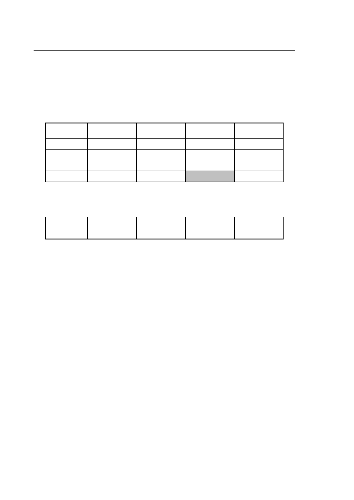
User Table Variables
The User Table (refer to Chapter 3 in the "PLUS Application Manual") has 100 records, each one
of which is made up of 4 variables, for a total 400 variables. The variable index ranges from 0 to
399.
The records and the variables stored in them are arranged sequentially, as shown in the following
table:
Record N° Variable 1 Variable 2 Variable 3 Variable 4
000001 L0 L1 L2 L3
000002 L4 L5 L6 L7
000003 L8 L9 L10 L11
000004 L12 L13 L14 L15
...............
...............
000099 L392 L393 L394 L395
000100 L396 L397 L398 L399
To calculate the index when the position of the cell in the table and the variable are known, the
following formula can be used:
Index = (Record Number - 1) x 4 + (Number of the variable in the record - 1)
For example, the index of the highlighted cell in the table is as follows:
Index = (4 - 1) x 4 + (3 - 1) = 14
To calculate the record number and the variable when the index is known, the following formula
may be used:
Record = (Index / 4) + 1
Variable = [Remainder of (Index / 4)] + 1
For example, L145 addresses record 37 (145 / 4 + 1) and variable 2 (remainder of the division + 1
= 1 + 1).
1-4 10 Series CNC ASSET Reference Manual (06)

Chapter 1
General
PLUS Tables Variables
PLUS Tables include the Axes Tables, the Tools Tables and the Tools Offsets Tables. The
contents of these tables are normally handled by the machine logic. Each PLUS Table is made up
of a given number of pages which contain the parameters that describe the object of the table. The
number of pages in each table is as follows:
Table N° of Pages Contents
Axes table 32 Axes identification
Tools Table 250 Record number in the table
Tool OffsetsTable 300 Tool offsets number
The table page number coincides with the index that follows the variable name.
The type, number and symbol of a parameter vary from table to table. The sections that follow
illustrate a typical page of each table. For further information about these tables, refer to Chapter 3
of the "PLUS Application Manual".
The ASSET instruction LCK permits to write protect PLUS tables. When write protection is active,
PLUS tables may be accessed only via ASSET. More information about the LCK triliteral is
provided in the final section of this chapter.
Values read or written in PLUS tables using ASSET are not affected by the
current unit of measure (G70/G71) but are considered as absolute values. It
should be remembered therefore that any numeric values representing
lengths are with reference to the machine's unit of measure configured in
AMP; it is up to the operator to perform any conversion required.
10 Series CNC ASSET Reference Manual (06) 1-5

Chapter 1
General
Axes Table
Each of the 32 pages in this table is made up of 19 fields identified by a name, as shown in the
example below. The index of each variable can range from 1 through 32 and corresponds to the
axes ID. The index may be a numerical value or another variable.
Field Type Variable name Format Meaning
reserved reserved --- --- ---
AXNAME read only $AXNAME(x) S axis name in ASCII
AXORIG read only $AXORIG(x) D value of current origin
reserved reserved --- --- ---
AXOFG92 read only $AXOFG92(x) D current G92 offset value
AXTOFF read only $AXTOFF(x) D current tool offset value
PRO_OFFS read only $PRO_OFFS (x) D total current corrector value
applied by the process when an 'h'
is enabled
TOT_OFFS read only $TOT_OFFS(x) D total offset of the current axis
ORIG1 read/write $ORIG1(x) D value of origin # 1
ORIG2 read/write $ORIG2(x) D value of origin # 2
ORIG3 read/write $ORIG3(x) D value of origin # 3
ORIG4 read/write $ORIG4(x) D value of origin # 4
ORIG5 read/write $ORIG5(x) D value of origin # 5
ORIG6 read/write $ORIG6(x) D value of origin # 6
ORIG7 read/write $ORIG7(x) D value of origin # 7
ORIG8 read/write $ORIG8(x) D value of origin # 8
ORIG9 read/write $ORIG9(x) D value of origin # 9
ORIG10 read/write $ORIG10(x) D value of origin # 10
reserved reserved --- ---
x = page number or axis identification number
S = short, D = double
Example:
To write into variable E1 the value of the current total offset of the axis identified by ID4, which is
the sum of the axis origin, the G92 offset and the tool offset, key in the following instruction:
E1 = $TOT_OFFS(4)
To assign to the origin # 1 of the axis identified by ID 5 the numerical value 1.4, key in the
following:
$ORIG1(5) = 1.4
1-6 10 Series CNC ASSET Reference Manual (06)

Chapter 1
General
Tools Table
Each of the 250 records of the table has 13 fields whose ID's are shown in the following diagram.
Each variable can take an index from 1 to 250. They can be expressed by a number or an E
parameter.
Field Type Variable name Format Meaning
TCODE read/write $TCODE(x) T** tool code
TOOLPOS* read/write $TOOLPOS(x) S Information regarding the tool position
TFAMCOL read/write $TFAMCOL(x) S reserved
TOOLTYPE* read/write $TOOLTYPE(x) S Information regarding the type of tools
TSTATUS read/write $TSTATUS(x) S tool status
TCNTRL read/write $TCNTRL(x) S tool control word
MAXLIFE read/write $MAXLIFE(x) D Initial life
REMLIFE read/write $REMLIFE(x) D real life
TUSER1 read/write $TUSER1(x) D User variable # 1 for tool
TUSER2 read/write $TUSER2(x) D User variable # 2 for tool
TUSER3 read/write $TUSER3(x) D User variable # 3 for tool
TUSER4 read/write $TUSER4(x) D User variable # 4 for tool
TOLOFNR read/write $TOLOFNR(x) S default tool offset number
x = page number or tool record number
S = short, D = double
* = these fields of the table may have various meanings depending on the configuration and on
how they are used by the machine logic (see the 10 Series User Manual for details).
** = integer number (max. 12 digits)
Example:
To read the code of the tool stored in record 35 key in the following function:
(DIS, $TCODE(35))
To assign to the tool stored in record 42 a life equal to 500 cycles, key in the following:
$LIFETYPE(42) = 3
$MAXLIFE(42) = 500
10 Series CNC ASSET Reference Manual (06) 1-7
Chapter 1
General
Tool Offsets Table
Each of the 300 pages or tool offsets in this table is made up of 9 fields. Each field is identified by a
name which is shown in the table below. Variable indexes range from 1 to 300. An index may be a
numerical value or another variable.
Field Type Variable name Format Meaning
TACTL1 read/write $TACTL1(x) D current tool length # 1
TCMAXL1 read/write $TCMAXL1(x) D maximum offset for length # 1
TCACTL1 read/write $TCACTL1(x) D current offset for length # 1
TACTL2 read/write $TACTL2(x) D current tool length # 2
TCMAXL2 read/write $TCMAXL2(x) D maximum offset for length # 2
TCACTL2 read/write $TCACTL2(x) D current offset for length # 2
TDIAMETER read/write $TDIAMETER(x) D tool diameter
TCACDIAM read/write $TCACDIAM(x) D diameter offset value
TORIENT read/write $TORIENT(x) S tool orientation
x = page number or offset number
S = short, D = double
Example:
If you want to supply the maximum requalification of the length # 1 of the corrector 137 with the
value in the user # 3 variable in the Tool Table at record 35, write:
$TCMAXL1(137) = $TUSER3(35)
If the value of process variable TTR (Thoroidal Tool Radius) has been set or
configured as 1, the fields relating to length # 2 are assumed to coincide with
the size of the tool tip radius (in TCP and HSM applications).
1-8 10 Series CNC ASSET Reference Manual (06)

Chapter 1
General
PLUS I/O
PLUS inputs are arranged in 85 11-bit arrays followed by 427 16-bit arrays; outputs are arranged in
85 6-bit arrays followed by 427 16-bit arrays. Accordingly, a total of 7767 inputs and 7342 outputs
has to be managed.
An array and its Input or Output are identified by an I or an O preceded by $ and followed by the bit
index between brackets: $I(index) or $O(index), as in the User Table. For example, $I(35),
$O(812).
The Input/Output arrays can be pictured as tables, as shown in the figures below.
Inputs (the first 85 arrays)
Arrays or groups of inputs may be numbered from 00 to 84, whereas the 11 bits in the array are
numbered from 0 to 10. The index of the first input variable will be 0, whereas the index of the last
input variable will be 934, as shown in the table below:
Array bit 0 bit 1 bit 2 bit 3 bit 4 bit 5 bit 6 bit 7 bit 8 bit 9 bit 10
00
01
02
03
$I(0) $I(1) $I(2) $I(3) $I(4) $I(5) $I(6) $I(7) $I(8) $I(9) $I(10)
$I(11) $I(12) $I(13) $I(14) $I(15) $I(16) $I(17) $I(18) $I(19) $I(20) $I(21)
$I(22) $I(23) $I(24) $I(25) $I(26) $I(27) $I(28) $I(29) $I(30) $I(31) $I(32)
$I(33) $I(34) $I(35) $I(36) $I(37) $I(38) $I(39) $I(40) $I(41) $I(42) $I(43)
.........................
.........................
83
84
$I(913) $I(914) $I(915) $I(916) $I(917) $I(918) $I(919) $I(920) $I(921) $I(922) $I(923)
$I(924) $I(925) $I(926) $I(927) $I(928) $I(929) $I(930) $I(931) $I(932) $I(933) $I(934)
To calculate the index from the cell position, i.e. when the array and bit numbers are known, use
this formula:
Index = array number x 11 + bit number
For example, to address bit 7 from array 03, the $I variable must be assigned the following index:
Index = 3 x 11 + 7 = 40
The resulting variable will be $I(40), as shown in the table.
To calculate the array and bit numbers from the index, divide the index by 11: the ---- will be the
array number and the remainder will indicate the bit number.
For example, the $I(172) variable will address the 15 (172 / 11) array and the 7 (172 - 15 x 11) bit.
10 Series CNC ASSET Reference Manual (06) 1-9

Chapter 1
General
Inputs (after the 85th array)
The numbering of the individual input arrays or input groups goes from 85 to 511; the 16 bits within
an array are numbered from 0 to 15. In these conditions the index of the first input variable will be
935, the index of the last variable will be 7766, as can be seen from the table below:
Array bit 0 bit 1 bit2bit3bit4bit5bit6bit7bit8bit9bit10bit11bit12bit13bit14bit 15
85
86
$I(935) $I(936) $I(950)
$I(951) $I(952) $I(966)
..........................
..........................
Array bit 0 bit 1 bit2bit3bit4bit5bit6bit7bit8bit9bit10bit11bit12bit13bit14bit 15
510
511
$I(7735) $I(7736) $I(7750)
$I(7751) $I(7752) $I(7766)
The formula used to define an index starting from the position of the cell (i.e., the array number and
the bit number), is as follows:
index = (array number – 85) X 16 + 935 + bit number
For example, if we want to address bit 13 in array 86 (i.e., the grey-coloured cell), the index of
variable $I must be determined as follows:
Index = (86 – 85) X 16 + 935 +13 = 964
In this case, the variable will therefore turn out to be $I(964), as shown in the table. Conversely, if
we want to determine an array and a bit, knowing the relative index, we must subtract 935 from the
index and then divide the value obtained by 16. By adding 85 to the whole number determined in
this manner, we get the array number, while the difference will identify the bit within the array. For
example: for variable $I (7736) we get array 510 ((7736-935)/16+85) and bit 1 ((7736-935) / 16).
1-10 10 Series CNC ASSET Reference Manual (06)

Chapter 1
General
Outputs (the first 85 arrays)
Arrays or groups of outputs may be numbered from 00 to 84, whereas the 6 bits in the array are
numbered from 0 to 5. The index of the first output variable will be 0, whereas the index of the last
output variable will be 509, as shown in the table below:
Array bit 0 bit 1 bit 2 bit 3 bit 4 bit 5
00 $O(0) $O(1) $O(2) $O(3) $O(4) $O(5)
01 $O(6) $O(7) $O(8) $O(9) $O(10) $O(11)
02 $O(12) $O(13) $O(14) $O(15) $O(16) $O(17)
03 $O(18) $O(19) $O(20) $O(21) $O(22) $O(23)
...................
....................
83 $O(498) $O(499) $O(500) $O(501) $O(502) $O(503)
84 $O(504) $O(505) $O(506) $O(507) $O(508) $O(509)
To calculate the index from the cell position, i.e. when the array and bit numbers are known, use
this formula:
Index = array number x 6 + bit number
Examples:
1. To address bit 2 from array 03, the $O variable must be assigned the following index:
Index = 3 x 6 + 2 = 20
The resulting variable will be $O(20), as shown in the table.
2. To calculate the array and bit numbers from the index, divide the index by 16: the integer value
obtained through the division will be the array number and the remainder will indicate the bit
number.
For example, the $O(214) variable will address the 35 (214/6) array and the 4 (214 - 35 x 6) bit.
10 Series CNC ASSET Reference Manual (06) 1-11

Chapter 1
General
Outputs (after 85th array)
The numbering of the individual output arrays or output groups goes from 85 to 511; the 16 bits
within an array are numbered from 0 to 15. In these conditions the index of the first output variable
will be 510, the index of the last variable will be 7341, as can be seen from the table below:
Ar
bit 0 bit 1 bit2bit3bit4bit5bit6bit7bit8bit9bit10bit11bit12bit13bit14bit 15
ray
$O(510) $O(511) $I(525)
85
$O(526) $I(527) $I(541)
86
..........................
..........................
Ar
bit 0 bit 1 bit2bit3bit4bit5bit6bit7bit8bit9bit10bit11bit12bit13bit14bit 15
ray
510
511
$O(7310) $O(7311) $O(7325)
$O(7326) $O(7327) $0(7341)
The formula used to define an index starting from the position of the cell (i.e., the array number and
the bit number), is as follows:
index = (array number – 85) X 16 + 510 + bit number
For example, if we want to address bit 7 in array 86 (i.e., the grey-coloured cell), variable $O must
be assigned the following index:
Index = (86 – 85) X 16 + 510 + 7 = 533
In this case, the variable will therefore turn out to be $O(533), as shown in the table. Conversely, if
we want to determine an array and a bit, knowing the relative index, we must subtract 510 from the
index and then divide the value obtained by 16. By adding 85 to the whole number determined in
this manner, we get the array number, while the difference will identify the bit within the array. For
example: for variable $O (680) we get array 95 ((680-510)/16+85) and bit 10 ((680-510) / 16).
1-12 10 Series CNC ASSET Reference Manual (06)

Chapter 1
General
FILE
10 Series ASSET can manage two types of files:
• ASCII files
• Binary (data) files
Except where otherwise stated, these files are located in default directory E:\FILE or F:\FILE, which
ASSET can access. However it is also possible to read or write with ASSET in files belonging to
other directories. In this case, the full pathname and extension of the file in question must be
specified (e.g. E:\USER\FILE|FILE1.DAT).
These files are located in the E:\FILE or F:\FILE directories, which are accessible to ASSET. Their
main characteristics are discussed in the sections that follow.
ASCII files
ASCII files may contain part programs, messages, etc. They are not formatted and have records of
undefined length that must be written and read sequentially. ASCII files are given the .ASC
extension by the system by default, in cases where the file was opened in read or write mode
without the full pathname and extension being specified.
In an ASCII file it is not possible to read, write or search for a specific record. Maximum record
length is 127 characters.
The system always starts reading an ASCII file from the first record, on which it positions
automatically as it opens the file.
Writing an ASCII file means adding a new record after the last record in the file. To edit an ASCII
file it is necessary to read it sequentially, make the necessary alterations and write a new file that
will replace the old one.
10 Series CNC ASSET Reference Manual (06) 1-13

Chapter 1
General
Binary files
Binary files are formatted files that are used for storing the parameters managed by the system, i.e.
variables, numbers, parameters, etc. Records have a fixed length that is declared when the first
record is written. Binary files are given the .DAT extension by the system by default, in cases
where the file was opened in read or write mode without the full pathname and extension being
specified.
For example, to write into a file the tool code with the relevant TUSER1-4 user variables the binary
file record will be as follows:
TCODE TUSER1 TUSER2 TUSER3 TUSER4
When the system writes the first record it automatically creates a header that is invisible to the user
and defines the format of all the file records.
Binary file records can be searched for and addressed for reading and writing operations.
A record can be up to 300 bytes long.
To calculate the record length in bytes it is necessary to know the length of each of the variables
stored in the record. This information is listed in the table below:
Variable Length in bytes
Boolean 1
Byte 1
Short 2
Long 4
Real 4
Long Real (Double) 8
String Number of characters in the string.
For example: SC0.4 --> 4 characters --> 4 bytes
Example:
if you write the following variables into a table:
(WRT,1,E1,E5,L3)
The record will occupy 24 bytes because there are 3 double variables and 3 x 8 = 24
For the following writing command:
(WRT,1,SC0.60,L5,"TEST")
the record length will be 72 bytes (60 + 8 + 4).
Unless otherwise specified in the reading or writing command, access to the file occurs at the first
record for reading and after the last record for writing. After a record has been read or written the
cursor will position to the subsequent record.
When reading or writing commands including ASSET binary files it is possible to declare a
parameter that specifies the number of the target record.
1-14 10 Series CNC ASSET Reference Manual (06)

Chapter 1
General
COMMANDS
ASSET ensures full compatibility with the commands and instructions typical of the standard
programming environment. For more information about parametric programming, please refer to
Chapter 7 of the 10 Series Programming Manual.
Here is a list of syntactic and typographical conventions used throughout the manual:
The function name and the mandatory signs will be printed in boldface type. Mandatory parameters
associated to a function will be indicated by an italicised mnemonics. Parameters may be enclosed
between brackets.
[ ] Square brackets enclose optional parameters that may be omitted. Do not write these
brackets into the block.
{ } Graphs enclose parameters that are alternative to one another and are separated by a |. Do
not write graphs into the block.
| The vertical bar is the separator between two alternative parameters. Do not write this bar into
the block.
Parameters may be expressed by letters, alphanumeric characters and numbers. Letters are used
as keys or to identify the characteristic of a command. Alphanumeric characters identify file and
variable names and are used for messages. Numbers identify parameters, multiple elements, etc.
Non significant zeroes can be omitted.
Example:
(OPN, channel, filename, {A|B}, {R|W})
The three-letter code, the commas and the brackets are mandatory. A is alternative to B and R is
alternative to W.
The sections that follow describe ASSET functions. For each function the following information is
provided:
• Function name
• Meaning
• Syntax
• Mandatory and optional parameters
• Other characteristics and notes
• Examples.
10 Series CNC ASSET Reference Manual (06) 1-15

Chapter 1
General
LCK - Locking/Unlocking PLUS tables
This instruction permits to inform the logic or other applications that the specified table is being
edited and is not accessible to them. After the table has been edited it is necessary to give another
LCK in order to indicate that the table is available.
Syntax:
(LCK, table number, {0 | 1})
where:
table number Is a number from 1 to 4 that identifies the write protected table. It can be
expressed as a numerical value, a local variable or a system variable with the
following mening:
1 axes table (origins)
2 tools table
3 tool offsets table
4 user table (L variables).
0 | 1 Write 1 to indicate that the specified table is write protected by ASSET. If the
table is already reserved by another user, such as PLUS or Table Editor, an
error message will be displayed:
NC270 PLUS Table already locked
This error can be managed from program by setting ERR = 1. For more
information refer to Appendix B.
Write 0 to indicate that the table is no longer reserved for ASSET and can be
accessed by other users.
Characteristics
$xxxxxx or L variables are always accessible and need not be write protected with ASSET.
However, it is recommended to lock the table to make sure that no other user has access to the
memory area written by ASSET.
Use LCK to unprotect a table only when it has been write protected from part program. Otherwise,
you may unprotect a table that was reserved for other users (such as the machine logic).
1-16 10 Series CNC ASSET Reference Manual (06)

Example:
The following example shows how to write variables into the Tools Table:
. . .
. . .
ERR = 1 enables error management from part program
"LOOP"
(LCK,2,1)
(GTO,LOOP,STE=45) 45 = write protected table; waiting for unlocking command
$TCODE(1) = 12
$TUSER1(1) = 3.45
$TCODE(2) = 13
$TUSER1(2) = 6.21
(LCK,2,0) unprotected tools table
ERR = 0 disables error management from part program
. . .
. . .
Chapter 1
General
10 Series CNC ASSET Reference Manual (06) 1-17

Chapter 1
General
END OF CHAPTER
1-18 10 Series CNC ASSET Reference Manual (06)

Chapter 2
INPUT COMMANDS
Input commands permit to create, customise and manage data entry windows. In particular, they
make it possible to:
• Define the labels of the data entry fields and the destination of input data;
• Define the layout of the data entry window: window size and position, text position, etc.
• Define the background, foreground and text colors.
The three-letter codes that allow to program these features are as follows:
• DIF
• INP
10 Series CNC ASSET Reference Manual (04) 2-1

Chapter 2
Input Commands
DIF - Definition of a data field
DIF permits to define the size and color of a data entry window that has been programmed with the
INP command. It must be used when the characteristics to be configured are different from the
default ones.
Syntax
(DIF, window number, first line, first column, first field line, first field column, empty lines, number
of fields [,background color, text color, field color])
where:
window number identifies a predefined window. It is an integer from 1 to 10. DIF,0 invokes the
default window, which cannot be modified.
first line is the screen line where the data entry window starts. It is an integer from 0 to
18.
Line 19 is always reserved for error messages.
first column is the screen column where the border of the window is positioned. It is an
integer from 0 to 79 which must obviously be selected according to the length of
the displayed data.
first field line is the line occupied by the first window field declared in the INP block. This field
may be the name of the window or a data field.
It is a value in the 0 to 18 range which depends on the value of the first line
parameter.
first field column is the screen column occupied by the first INP field and measures the distance
from the screen border to the window border in characters. If programmed with
the INP command the field will be automatically centered.
It is an integer from 0 to 79 which must obviously be selected according to the
length of the displayed data.
empty lines is the number of empty lines that separates two subsequent comment or field
lines.
It is an integer from 0 to 18 which must obviously be selected according to the
available space and the length of the displayed data. If you write 0 there will be
no empty lines.
If INP programs only one data entry field, the empty lines value is use for
positioning the lower border with respect to the last displayed line.
number of fields specifies the number of fields to be displayed on the same line. It ranges from 1
to 4. The distance between two fields is 3 characters.
background color (optional) Defines the color of the data entry window background. If it is omitted,
the default background color is blue. Allowed values are between 0 and 7. The
meaning of these values is shown in the Characteristics section.
2-2 10 Series CNC ASSET Reference Manual (04)

Chapter 2
Input Commands
text color (optional) Defines the color of the name and text displayed in the data entry
window. If it is omitted, the default color is yellow. Allowed values are between
0 and 7. The meaning of these values is shown in the Characteristics section.
field color (optional) Defines the color of the characters and markers entered from the
keyboard on the fields programmed with INP. If it is omitted, the default color is
white. Allowed values are between 0 and 7. The meaning of these values is
shown in the Characteristics section.
Characteristics
• The parameters configured in the background color, text color and field color are as follows:
1. black
2. blue
3. green
4. cyan
5. red
6. magenta
7. yellow
8. white
• The window layouts established by DIF are retained in the system memory after a reset.
10 Series CNC ASSET Reference Manual (04) 2-3

Chapter 2
Input Commands
• All the fields in the DIF instruction (included the colors) may be programmed directly, i.e., by
writing numerical values, or through local and system variables.
• ASSET includes a default DIF instruction. If no DIF is declared in the INP instruction, the default
DIF displays the following window. This window implies that INP has declared 8 fields plus the
WINDOW NAME. The numbers of lines and columns are in italics. Default window parameters
are as follows:
column 0 column 79
PROCESS CONTROLLED: 1 CAPS ON DATE: 15/12/1993 TIME: 9:35:00
PROC: 1 IDLE AUTO OPT STOP RETRACE
0
1
2
FIELD 1: xxxxxxxxxx
3
4
FIELD 2: xxxxxxxxxx
5
6
FIELD 3: xxxxxxxxxx
7
8
FIELD 4: xxxxxxxxxx
9
10
FIELD 5: xxxxxxxxxx
11
12
FIELD 6: xxxxxxxxxx
13
14
FIELD 7: xxxxxxxxxx
15
16
FIELD 8: xxxxxxxxxx
17
18
(Reserved for error messages)
19
MACHINE SETUP TABLES DIAGNOSTICS PERIPHERALS UTILITY
WINDOW NAME
POS DISPLAY NEXT DISPLAY SELECT PROCESS ENLARGE HELP
AUTO MANUAL PART PROGRAM VARIABLES OEM SOFTKEY
First line: 0
First column: 0
First field line: 1
First field column: 1
Empty lines: 1
Number of fields on a line: 1
Background color: Blue
Label color: Yellow
Field color: White
These parameters are programmed by the following DIF format:
(DIF,1,0,0,1,1,1,1,6,7,4) (the last three digits can be omitted)
2-4 10 Series CNC ASSET Reference Manual (04)

Chapter 2
Input Commands
Examples:
Let's assume that you need to program a data entry window (WINDOW #3) that is made up of
three fields and one window name, like the one shown in the figure below:
column 0 column 79
PROCESS CONTROLLED: 1 CAPS ON DATE: 15/12/1993 TIME: 9:35:00
PROC: 1 IDLE AUTO OPT STOP RETRACE
0
1
2
3
4
5
6
7
8
9
10
11
12
13
14
15
16
17
18
19
POS DISPLAY NEXT DISPLAY SELECT PROCESS ENLARGE HELP
MACHINE SETUP TABLES DIAGNOSTICS PERIPHERALS UTILITY
FIELD 1: xxxxxxxxxx
FIELD 2: xxxxxxxxxx
FIELD 3: xxxxxxxxxx
AUTO MANUAL PART PROGRAM VARIABLES OEM SOFTKEY
WINDOW NAME
The number of fields, the field lengths, the characters in the window name and the fields labels
(FIELD 1 through 3) are specified in the INP file.
Let's also assume that the window must be positioned as follows:
distance from the upper border to the status line: 3 lines
distance from the window border to the screen border: 10 characters
distance from the window name to the upper window border: 1 line
distance from the first field to the left window border: 1 character
number of empty lines between fields: 1
number of fields per line: 1
The format of the DIF command will be:
(DIF,3,3,10,1,1,1,1)
10 Series CNC ASSET Reference Manual (04) 2-5

Chapter 2
Input Commands
To display blue comments and red inputs on a green background, the format of the DIF command
will be:
(DIF,3,3,10,1,1,1,1, 2,1,4)
These numbers may be partially or totally replaced by local or system variables. For example, if the
contents of the first line, first column, and first field column fields are stored in variables E1, E2 and
E3, the format of the above command must be:
(DIF,3,E1,E2,1,E3,1,1)
If a great many fields must be displayed in one window it is possible to write several fields on the
same line with the following format:
(DIF,5,3,5,1,3,1,3)
The 6 fields programmed with INP will display this window:
WINDOW NAME
FIELD 1: xxxxxxxxxx FIELD 2: xxxxxxxxxx FIELD 3: xxxxxxxxxx
FIELD 4: xxxxxxxxxx FIELD 5: xxxxxxxxxx FIELD 6: xxxxxxxxxx
2-6 10 Series CNC ASSET Reference Manual (04)

Chapter 2
Input Commands
INP - Manual data input
This command permits to link manual data inputs to their destination variables. It is used for
programming the name of the data entry window and the field labels. Data will be arranged
according to the window size and layout established with DIF. If the default DIF suits the user
needs the window number may be omitted.
When INP is executed, it enables the MDI mode.
Syntax
(INP, [Nwindow number,] [T WINDOW NAME,] label, label length, variable
[,label, label length, variable]
[,label, label length, variable]
[,label, label length, variable]
[,label, label length, variable]
[,label, label length, variable]
[,label, label length, variable]
[,label, label length, variable])
where:
window number (optional) It is the number of data entry window established with DIF.
It may be a number in the 0 to 10 range written in the command line or read
from a variable.
0 is the default window number, which is associated to the window described by
the DIF command.
window name (optional) It is the label displayed on the first window line. It may be a character
string enclosed between quotes ( ' or " ) or a string variable. For example,
SC0.10.
Its maximum length is 40 characters. The name is automatically centered on the
first window line.
Each data entry window may contain up to 8 fields. Each field is configured by the following
parameters:
label Is the name of the field. For example: tool, feedrate, etc.
It may be a character string enclosed between quotes ( ' or " ) or a string
variable. For example, SC0.10.
The label length may range from 0 and the value specified by the label length
parameter. The maximum label length is 40 characters.
label length Specifies the maximum length of the field label. The programmer may use this
parameter to arrange various fields on one line regardless of the length of the
label string.
It may be a number written in the command line or read from a variable.
variable It is a local or system variable whose current value is displayed on the data
entry window and updated with manual data input.
10 Series CNC ASSET Reference Manual (04) 2-7

Chapter 2
Input Commands
Characteristics
When the system reads an INP block it switches to the MDI mode and displays the programmed
data entry window with the current variable values specified in the INP command.
The size, position and colors of the data entry window are programmed by the DIF instruction
whose number is specified in the INP command. If this number is omitted, the data entry window
will have the default characteristics.
Displayed values may be edited with the same procedures described for the other data entry
windows.
To exit from the data entry window and quit the MDI mode, press [ESC], [Enter], [Page Up], [Page
Down], [Home] and [End].
By pressing [ESC], [Page Up], [Page Down], [Home] and [End] the input window is closed but the
values of the programmed variables are not updated with the values you may have entered. In this
case, the STE system variable assumes a value that indicates the type of key with which the input
window has been closed. The possible values are the following:
Type of key STE value with ERR = 0
ESC
PAGE UP
PAGE DOWN
HOME
END
20
22
23
24
25
Press [Enter] to close the window saving the alterations to programmed values. If a format error is
detected in the assignment (for example, if VEF is assigned a value outside the 0.1 - 8.0 range) it
can be managed from program by setting the ERR variable to 1 (refer to Chapter 6, "Error
Management from Part Program").
The system automatically synchronises (#) the INP command to the execution of the program
(refer to Chapter 1 in the Programming Manual).
NOTE:
The label length must be programmed according to the number of fields that need to be displayed
on the same line. To well align fields on the same columns it is advisable to assign the same label
length to all the fields. This value must be equal to or greater than that of the longest label.
The system will not visualise an error message as long as it can display at least
one digit from the current or input data assigned to the right-most fields on the
window.
This should be remembered when programming position of the window on the
screen and the data fields in it and the label length.
It is recommended to display all the digits in the various data entry fields.
2-8 10 Series CNC ASSET Reference Manual (04)

Chapter 2
Input Commands
Examples:
E1 = 1000; feedrate
(INP,'FEEDRATE',15,E1)
The above commands permit to visualise a data entry window whose size and colors are specified
by the default parameters in the DIF command. This window will visualise the "FEEDRATE" label
followed by a 7 character space (7 = 15 - the actual label length) and the current value of the E1
variable (1000 in the example). This value may be altered from keyboard or confirmed with [Enter].
(INP,T'INPUT TEST','FIELD 1',20,SC0.20)
This command permits to display a data entry window whose name is "INPUT TEST" and a 20
character field to display the contents of the SC0.20 variable preceded by the "FIELD 1" label.
(INP,N1,'FIELD 1',20,SC0.20,"FIELD 2", 20, E3,'FIELD 3',20,@PLUS)
This command permits to display a data entry window whose characteristics are specified by DIF 1,
without name, and in which the contents of the SC0.20, E3 and @PLUS variables are preceded by
the "FIELD 1", "FIELD 2" and "FIELD 3" labels.
10 Series CNC ASSET Reference Manual (04) 2-9

Chapter 2
Input Commands
END OF CHAPTER
2-10 10 Series CNC ASSET Reference Manual (04)

Chapter 3
SCREEN MANAGEMENT COMMANDS
10 Series displays all the parameters and data requested for system operation on a screen made
up of 25 lines. Each line has 80 characters. Screen lines are divided as follows.
• 1 status information line
• 21 lines (data area) displaying process and task information.
• 3 softkey lines.
The status line and the softkey lines are managed by the system. The data area may visualise two
screen types:
• Full screens: occupy 21 80-character lines.
• Quadrants: occupy 10 39-character lines.
The screens used on the 10 Series are of two types:
• System screens: the information in these screens is displayed through the system software;
see the user manual for significance of this information.
• User screens: contain information displayed by the user by way of the machine logic functions,
or using the ASSET OUT instruction.
10 Series CNC ASSET Reference manual (07) 3-1

Chapter 3
Screen Management Commands
Code Screen
Type
Description Modified with
ASSET?
1 (*) Main process screen No
2 (*) Main logic screen No
3 (*) Axes coordinate in large font No
4 (*) Logic screen 1 Yes
5 (*) Logic screen 2 Yes
6 (*) Logic screen 3 Yes
7 (*) Logic screen 4 Yes
8 (*) Additional screen 1 No
9 (*) Additional screen 2 No
10 (*) Additional screen 3 No
11 (*) Additional screen 4 No
12 (*) Additional screen 5 No
25 (**) Logic quadrant 1 Yes
26 (**) Logic quadrant 2 Yes
27 (**) Logic quadrant 3 Yes
28 (**) Logic quadrant 4 Yes
35 (**) System status quadrant No
36 (**) Axes coordinates quadrant No
37 (**) Part program display quadrant No
38 (**) Process status quadrant No
39 (**) Programmed codes status quadrant No
40 (**) Axes offsets quadrant No
(*) Full screen size
(**) Quadrant
ASSET offers two, three-letter screen management commands:
• OUT for definition of the following line parameters:
− position
− contents (type of data, length, etc.)
− background and foreground colors
− font.
• SCR for selection of the screen associated with a given process.
3-2 10 Series CNC ASSET Reference manual (07)

Chapter 3
Screen Management Commands
OUT - Screen line parameters
OUT defines location, length, colors and fonts on a line basis.
Syntax
(OUT,Screen code, line, column, background color, data color, [/length,] variable, ... ,variable)
where:
Screen code Is the screen number provided by the table on page 3-2.
Allowed values are 4, 5, 6, 7, 25, 26, 27, 28, which correspond to the
tables that can be modified with ASSET and described in the previous
table. This parameter can be written with a numerical format or read from
a local or system variable.
line Is the line number. It ranges from 0 to 20 in full size screens or from 0 to
9 in quadrants.
This parameter can be written with a numerical format or read from a
local or system variable.
column Is the number of the column where the line starts. It ranges from 0 to 79
in full size screens or from 0 to 38 in quadrants. If the maximum value is
selected, i.e. 79 or 38, only one character will be displayed.
This parameter can be written with a numerical format or read from a
local or system variable.
background color Is the background color of the selected line. It ranges from 0 to 7 (refer to
the Characteristics paragraph in this section) and may be written with a
numerical format or read from a local or system variable.
data color Is the color of the contents displayed on the selected line. It ranges from
0 to 15 (refer to the Characteristics paragraph in this section) and may be
written with a numerical format or read from a local or system variable.
/length (optional) Is the length of the selected line. It ranges from 1 to the
maximum number of characters displayed between the selected column
number and the last column configured for that screen.
It may be written with a numerical format or read from a local or system
variable. In any case the slash ( / ) is mandatory.
variable,...,variable, Is the list of characters or numerical variables to be displayed on the line.
Up to 8 variables of the same or of different types are allowed. Strings of
characters must be enclosed between quotes ( ' or " ).
10 Series CNC ASSET Reference manual (07) 3-3

Chapter 3
Screen Management Commands
Characteristics
• The allowed values for background color and data color and their meaning are shown in the
table below:
Parameter value Background color Data color/display mode
0 Black Black / Normal
1 Blue Blue / Normal
2 Green Green / Normal
3 Cyan Cyan / Normal
4 Red Red / Normal
5 Magenta Magenta / Normal
6 Yellow Yellow / Normal
7 White White / Normal
8 Not allowed Black / Blinking
9 Not allowed Blue / Blinking
10 Not allowed Green / Blinking
11 Not allowed Cyan / Blinking
12 Not allowed Red / Blinking
13 Not allowed Magenta / Blinking
14 Not allowed Yellow / Blinking
15 Not allowed White / Blinking
• If both background color and data color are set to zero, the system will nevertheless default to
a white-on-black screen.
• To program a blank between variables when the line displays several variables, write the blanks
between quotes (for example, " ") or store them in a string variable, which may be repeated
several times in the same command.
• The contents specified in the OUT block must belong to the same line and cannot be longer
than the line. To display more data it is necessary to program more OUT's.
In addition, several parameters may be displayed on the same line by programming different
OUT blocks with appropriate line, column and length values so as to prevent overlapping.
3-4 10 Series CNC ASSET Reference manual (07)

Screen Management Commands
Example:
The following command:
(OUT,5,3,10,2,8,/60,"TEST VAR E1: ",E1," "TEST VAR SC0.10: ",SC0.10)
allows to display the following screen:
column 0 column 79
PROCESS CONTROLLED: 1 CAPS ON DATE: 15/12/1993 TIME: 9:35:00
PROC: 1 IDLE AUTO OPT STOP RETRACE
0
1
2
3
4
5
6
7
8
9
10
11
12
13
14
15
16
17
18
19
POS DISPLAY NEXT DISPLAY SELECT PROCESS ENLARGE HELP
MACHINE SETUP TABLES DIAGNOSTICS PERIPHERALS UTILITY
TEST VAR E1: 1254.0 TEST VAR SC0.10: ABCDEFGHIL
AUTO MANUAL PART PROGRAM VARIABLES OEM SOFTKEY
Chapter 3
A 60-character green bar starting on column 10 appears on line 3. Its contents will be displayed in
black and blinking. Note that the strings programmed between quotes end by blanks, which
prevents parameters from being displayed as an uninterrupted line.
This is screen 5 and is associated to logic screen 2.
With the following variables:
SN1 = 5
SN2 = 3
SN3 = 10
SN4 = 2
SN5 = 8
SN6 = 60
SC30.12 = "TEST VAR E1: "
SC5.19 = "TEST VAR SC0.10: "
the OUT command could be rewritten as follows:
(OUT,SN1,SN2,SN3,SN4,SN5,/SN6,SC30.12,E1," ",SC5.19,SC0.10)
10 Series CNC ASSET Reference manual (07) 3-5

Chapter 3
Screen Management Commands
SCR - Screen selection
SCR selects the video screen associated to the current process.
Syntax
(SCR,Screen code [, background color for initialization])
where:
Screen code Is the screen number provided by the table on page 3-2. It can be written
with a numerical format or read from a local or system variable.
If this number is > 100, the selected screen belongs to ProcessController
Windows application of WinNBI software.
background colour for
initialization (optional)
This parameter is taken into consideration only if the screen code
represents a screen that can be modified by ASSET. In this case, the
screen will be initialized with the color specified and all data previously on
that screen will be deleted. If this parameter is not specified, the screen
will not be initialized.
If the screen code is > 100 and background colour is > 0, the automatic
change of the screen selection is inhibited, possible on the Windows
application through F4 button.
Characteristics
If the system reads the command but no screen has been configured for the selected process the
visualised screen will not change. On the contrary, if the specified screen has been configured, it
will be immediately visualised.
The background color for initialization is defined by a number from 0 to 7, as illustrated in the table
below:
1. Black
2. Blue
3. Green
4. Cyan
5. Red
6. Magenta
7. Yellow
8. White
Screen change for ProcessController
If you want to select a ProcessController screen from Part Program, it is necessary to specify a
screen code > 100 in the SCR command. The number of the activated screen is “screen code –
100” and it is written into the SW5 variable with 15
th
bit=1 if background colour > 0.
3-6 10 Series CNC ASSET Reference manual (07)

Chapter 3
Screen Management Commands
Example 1:
Let's assume that the system controls three processes and that the following screens have been
associated to them:
Process 1: Screens 1, 3, 8
Process 2: Screens 1, 2, 9, 25
Process 3: Screens 1, 3, 8, 9
In addition, let's assume that the (SCR,8) command was programmed in process 2 when process 1
is selected. The system will display screen 8, which is associated to process 1. If the same
command were programmed when process 2 is selected, no changes would be noticed.
Example 2:
Let’s assume that the following screens have been configured in the ProcessController of WinNBI
software:
PROCESS 1: 1,3,8
In addition, let’s assume that the (SCR,108,1) command was programmed in process 1. The
system will display screen 8 which is associated to process 1 and the automatic change of screen
through F4 button will be inhibited.
10 Series CNC ASSET Reference manual (07) 3-7

Chapter 3
Screen Management Commands
END OF CHAPTER
3-8 10 Series CNC ASSET Reference manual (07)

Chapter 4
FILE MANAGEMENT COMMANDS
The system may control ASCII and binary data files. The characteristics of these files have been
discussed in Chapter 1.
ASSET file management commands make it possible to:
• open a file and link it to a management channel.
• read a binary file or a record sequentially.
• write or edit a binary file or a record sequentially.
• close any file opened by ASSET.
• delete a file.
• copy an ASCII file to the directory of programs.
• allocate and release physical devices for file access.
• copy a file
The functions quoted above are executed by the following three-letter commands, described in this
chapter:
− OPN
− REA
− WRT
− CLO
− DEL
− INS
− GDV
− RDV
− CPY
10 Series CNC ASSET Reference Manual (07) 4-1

Chapter 4
File Management Commands
OPN - Opening a file
This instruction permits to open a file and link it to a channel number. It also specifies whether the
file will be opened for reading or writing.
The channel is a marker that facilitates access to the file from other ASSET file management
commands.
Syntax
(OPN, channel, filename, {A | B | P}, {R | W})
where:
channel Is a number from 1 to 5 that identifies the channel. A channel is another file that
will be subsequently used by the REA or WRT commands.
It can be written in the block with a numerical format or read from the specified
variable.
filename Is the name of the file (max. 8 characters) associated to the channel. It may be
an alphanumerical string or the name of the character variable that contains the
file name. When it is a variable it must be preceded by a '?'.
The complete path and extension may be specified in the filename.
{A | B | P} Defines the type of file: ASCII (A), binary (B) or if a file belongs to the system
directory of programs (P).
{R | W} Specifies the type of access:
R: reading
W: writing
Characteristics
In each process it is possible to open 5 simultaneous files (channels).
If neither the path nor extension are specified in filename, the system provides the file extension
.DAT for binary files and .ASC for ASCII files. The file will be read or written in the default directory
(E:\FILE or F:\FILE).
If a file is opened for reading it must have been previously created and saved in the system. If the
file is opened for writing it need not exist in the system already and will be written in the working
directory when the session is closed.
4-2 10 Series CNC ASSET Reference Manual (07)

Chapter 4
File Management Commands
Examples:
1. The TEST ASCII file in directory E:\FILE may be opened for reading and associated to channel
1 by the following command:
(OPN,1, TEST,A,R)
2. If the name of the DATAFILE file is written in the SC0.8 variable:
E1=2
SC0.8 = "DATAFILE"
and the channel number is stored in the E1 variable, DATAFILE may be opened for reading and
associated to channel 2 with the following command:
(OPN,E1,?SC0.8,B,W)
The full pathname of the file is E:\FILE\DATAFILE.DAT.
3. With command:
(OPN,1,E:\TEST.KKK,A,R)
File ASCII E:\TEST.KKK is opened for reading.
10 Series CNC ASSET Reference Manual (07) 4-3

Chapter 4
File Management Commands
WRT - Writing a file
This command permits to write a record into the file specified and linked by a previous OPN block.
Data will be written sequentially, in the same order in which they are specified in the WRT block.
Syntax
(WRT, channel,[R record,] variable [, ...,variable])
where:
channel Is the channel number linked to the file by the previous OPN command. In
addition, OPN must have opened the file for writing (W).
record (optional) is a number or a variable that identifies the file record in which the
parameters must be written. It is always preceded by an R.
This parameter is accepted only if the file is binary.
If record is omitted, data will be written in the record used for the latest reading
and the system will position at the beginning of the subsequent record. If this is
the first writing instruction after OPN, data will be written on the first file record.
The maximum number of records that can be specified is 65535.
variable Is the variable(s) (max. 30) whose data must be written in the file records.
If the destination file is an ASCII file only character variables will be accepted.
If the destination file is binary, it is necessary to use the same number and type
of variables written in the first file record.
4-4 10 Series CNC ASSET Reference Manual (07)

Chapter 4
File Management Commands
Characteristics
If the file is binary (i.e. has been opened with the B marker) and the number of records in the file
has not been specified in WRT, data will be written in the record that follows the record written
during the last writing session. If there have been no previous writing sessions, data will be written
in the first file record.
The first data written on an empty binary file are the record type, the number of variables, the types
of variable and the sequence in which variables must be arranged. This record provides the access
pattern to be followed by subsequent reading or writing operations, in which the same number, type
and sequence of variables must be used.
For example, if the first writing operation was programmed by the following command:
(WRT,1,E1, SC3.4,@PLUS_SHORT(1))
that is, 1 double variable, 4 character variables and 1 short variable, subsequent writing or reading
commands will resemble the following:
(WRT,1,L1,"JOE",@PLUS_SHORT(4))
(REA,1,SN1,!TEST.4CH,@PLUS_SHORT(6))
If other formats, types or numbers of variables are used or if variables are arranged in a different
sequence, an NC248 Data file access error will occur.
In ASCII files data are always written in the last file record. To edit an ASCII file you must open it,
read it sequentially record by record, make the necessary alterations and write the records into a
new file under a new name.
Alterations will become effective only after the file has been closed. To read a just-altered file you
must first close it with CLO and then open it for reading.
Examples:
(WRT,1,SC5.80)
This command writes into the ASCII file associated to channel 1 the first 80 characters stored in the
SC5 variable.
(WRT,3,R12,E7,E8,E9)
This command writes into record 12 of the binary file associated to channel 3 the data stored in
variables E7, E8 and E9. The pointer remains at the beginning of record 13.
10 Series CNC ASSET Reference Manual (07) 4-5

Chapter 4
File Management Commands
REA (RED) - Reading a file
This commands reads a record from the file declared by the previous OPN command and specifies
the channel to which the file is associated.
Syntax
(REA, channel,[R record,] variable [, ...,variable])
where:
channel Is the channel number linked to the file by the previous OPN command. In
addition, OPN must have opened the file for reading (R).
record (optional) is a number or a variable that identifies the file record whose
parameters must be read. It is always preceded by an R.
This parameter is accepted only if the file is binary.
If record is omitted, the system will read the record used for the latest reading
and positions the pointer at the beginning of the subsequent record. If this is the
first reading instruction after OPN, data will be read from the first file record.
The maximum number of records that can be specified is 65535.
variable Is the variable(s) (max. 30) where read data must be written.
If the destination file is binary, it is necessary to use the same number and type
of variables written in the first file record. Otherwise, an NC248 error will occur.
If the destination file is an ASCII file, this procedure is not necessary because
the variable format conversion is performed automatically, based on the order of
reading.
Characteristics
The command may be expressed indifferently as REA or RED.
Binary File
If the file is binary (i.e. has been opened with the B marker) and the number of records in the file
has not been specified in REA, data will be read from the record that follows the one used during
the last reading session.
ASCII File
In an ASCII file (i.e. has been opened with the A marker), data will be read from the record on
which the pointer remained positioned since the last reading session.
The conversion of a numerical parameter into the input variable format is automatically performed.
The end of a numerical field is identified by a space, by a sign or by an alphabetical character; if at
least a numerical character has not been read during the reading of a numerical variable, the
system will visualise format error.
The end of a string field is identified by the number of characters specified by the input variable.
4-6 10 Series CNC ASSET Reference Manual (07)

Chapter 4
File Management Commands
If the number of variables specified in reading is different from number of fields present in a file
record, the system will not visualise an error message, but, it will write variables in sequence until
the record is completed.
Examples:
(REA,1,SC5.80)
This command reads from the ASCII file associated to channel 1 the first 80 characters stored in
the SC5 variable. (The maximum allowed string length is 80 characters).
(REA,3,R12,E7,E8,E9)
This command reads data from record 12 of the binary file associated to channel 3 and writes them
into variables E7, E8 and E9. The pointer remains at the beginning of record 13. The sample
record of this file is made up of 3 double variables.
Reading examples on ASCII file
Let’s assume that the record to be read from the ASCII file, associated to channel 1, consists of the
following fields:
-5.00 +3400 PLUTO
the commands resulting
(REA,1,E1,E2,E3) Format error because the character “P” is not numerical
(REA,1,SCO.8,E1,SC10.80) SCO=-5.00+3 E1=400; SC10=PLUTO
(REA,1,E1) E1=-5.00
After every reading is completed, the pointer will be positioned to the next record, so in the case of
the last reading example above the fields after –5.00 will be lost.
10 Series CNC ASSET Reference Manual (07) 4-7

Chapter 4
File Management Commands
CLO - Closing a channel
This command closes the file associated to the specified file. If the channel is omitted, all the
ASSET files opened by the process will be closed.
Syntax
(CLO [, channel])
where:
channel (optional) Is the channel number linked to the file in the OPN instruction.
Characteristics
If the channel is omitted, CLO will close all the ASSET files that have been opened by the process.
An alternative method for closing all the ASSET files that have been opened by the process is a
system reset.
Examples:
(CLO, 2)
This command closes the file associated to channel 2.
(CLO)
This command closes all the ASSET files that have been opened by the process.
4-8 10 Series CNC ASSET Reference Manual (07)

Chapter 4
File Management Commands
DEL (CAN) - Deleting a file
This command permits to delete the specified file from the working directory or the part program
directory.
Syntax
(DEL, filename, A|B|P)
where:
filename Is the name of the file.
Full pathname and extension may be specified in filename. If the path is not
specified, the file indicated present in the ASSET working directory (markers A
or B) or the part program file (marker P, with 48 characters max.) will be
deleted.
If filename is preceded by a ? the name of the file is stored in a local or system
variable.
A|B|P These markers describe the characteristics of the file:
A delete the ASCII file ( .ASC extension) indicated from the working directory,
if the path or extension were not specified
B delete the BINARY (data) file ( .DAT extension) indicated from the working
directory, if the path or extension were not specified
P delete the part program file specified from the system directory of
programs.
If the full pathname or extension is specified in filename, this parameter is not
taken into consideration.
Characteristics
The triliterals DEL or CAN, which may be used as alternatives, delete the specified file only if it is
not currently used by the system. If the file is a part program it will be deleted only if it has not been
selected by any process.
If the specified file does not exist, the NC238 File not found error code will be displayed. See
appendix B for a detailed description of how to manage this error from part program.
10 Series CNC ASSET Reference Manual (07) 4-9

Chapter 4
File Management Commands
Examples:
The following command
(DEL,TEST,A)
deletes the TEST ASCII file from the ASSET working directory.
This command
(DEL,?SC0.8,B)
deletes the binary command whose name is stored in the SC0.8 variable.
4-10 10 Series CNC ASSET Reference Manual (07)

Chapter 4
File Management Commands
INS - Saving an ASCII file in the directory of programs
This command permits to save the specified ASSET ASCII file in the directory of programs.
Syntax
(INS, filename, filenamepp, directory)
where:
filename Is the name of an ASCII file stored in the working directory, or another directory
if the full pathname was specified. It can be written as a string or read from a
text variable, in which case it is preceded by a question mark ( ? ).
filenamepp Is the name under which the ASCII file will be saved in the directory of
programs. It can be a 48 character string or the content of a variable, in which
case it is preceded by a question mark ( ? ).
directory Is a code (written as a numerical value or read from a local or system variable)
that specifies the logic subdirectory in which the ASCII file must be written:
Allowed values are:
1. PROGRAM directory
2. USER directory
3. SYSTEM directory
4. OEM directory
Characteristics
If no path or extension were specified, the file is taken from the default working directory (F:\FILE)
with the .ASC extension.
The part program file will be saved in the directory of programs without extension.
The file inserted in the directory of programs is deleted from the directory it was in before the INS
command.
Examples:
(INS,SAMPLE,PPTEST,0)
This command extracts the SAMPLE ASCII file from the F:\FILE directory and saves it in the
PROGRAM directory with the PPTEST name.
(INS,?SC7.8,?!USER3,4CH,1)
With this command the file whose name is stored in the SC7.8 variable will be saved in the USER
directory under the name stored in the USER !USER3.4CH variable.
10 Series CNC ASSET Reference Manual (07) 4-11

Chapter 4
File Management Commands
CPY - Copy a file
This command copies the file specified in the working directory or in the part program directory of
programs.
Summary
(CPY, filename1, filename2[,A/B/P,A/B/P[,directory]])
where:
filename1 Is the name of the file to be copied.
In filename1 you can specify the full file name or the file extension. If the path is
not specified only those files will be considered which are in the work directory
of ASSET (key A or B) or in the part program directory if the file contains a part
program (key P).
If filename1 is preceded by the key "?" this indicates a local or system variable
containing the name of the file to be copied.
filename2 Is the name of the destination file.
Filename2 follows the same rules described for filename1.
A/B/P (optional). These are the keys which specify the features of the files with
filename1 and filename2.
In particular:
A indicates that the specified file is an ASCII file (with extension .ASC)
belonging to the working directory (if the path or extension are not
specified).
B indicates that the specified file is a binary file (with extension .DAT)
belonging to the working directory (if the path or extension are not
specified).
P indicates that the specified file belongs to the part program directory.
directory (optional). A numeric code or the contents of a local or system variable which
indicates the logical directory where to copy the specified file.
Its value is 0 to 3 with the following meanings:
0 directory “PROGRAM”
1 directory “USER”
2 directory “SYSTEM”
3 directory “OEM”
4-12 10 Series CNC ASSET Reference Manual (07)

Chapter 4
File Management Commands
Characteristics
If the path is not specified, the system assumes as the default working directory (F:\FILE). In
addition, if no extension is specified, the system will add an extension based on the basis of the
specified key: .DAT for binary files (key B) or .ASC for ASCII files (key A).
Example:
Initial situation: file SOURCE.DAT is present in directory F:\FILE
correct syntaxes for Asset copy: (CPY , SOURCE.DAT , DEST.DAT)
(CPY ,SOURCE , DEST , B , B )
final situation: file SOURCE.DAT will be copied as DEST.DAT in the F:\FILE directory
In cases where the path has been specified it is not necessary to enter a key as the file will be
taken as indicated.
The parameter for the directory is significant if filename1 does not belong to the program directory
and is to be copied into it or if filename1 belongs to the program directory (key P) and is to be
copied into a logical directory different to the one to which it belongs.
10 Series CNC ASSET Reference Manual (07) 4-13

Chapter 4
File Management Commands
END OF CHAPTER
4-14 10 Series CNC ASSET Reference Manual (07)

Chapter 5
PROCESS MANAGEMENT COMMANDS
The ASSET commands described in this chapter (RTP, ROP, GPS, RAP and PLS) permit to read
the following parameters of the selected process:
• current or programmed tool number
• current or programmed tool offset number
• process state and mode
• axis coordinates.
Data read by these commands are sent to the process defined by the PRO block. Although PRO is
not an ASSET but a standard command, it has been included in this chapter for the sake of clarity.
The process number may also be specified in the ASSET reading command. If it is omitted, the
system will default to the process specified by PRO. If no PRO has been programmed, the data will
be sent to the same process that is executing the ASSET command.
The above parameters can be read using the three-letter commands listed below and described in
this chapter:
− PRO
− RTP
− ROP
− GPS
− RAP
In addition to the above commands, there is also a general purpose command with which SW
PLUS variables can be read both inside and outside a process. This command is:
− PLS
10 Series CNC ASSET Reference Manual (07) 5-1

Chapter 5
Process Management commands
PRO - Definition of the default process
This standard programming instruction permits to specify a default process. This process includes
both the synchronization commands and the ASSET commands described in the chapter.
Syntax
(PRO, process number)
where:
process number Is a number from 1 to 20 that identifies the process. It can be written as a
numerical value or read from a local or system variable.
By resetting the system or invoking another program it is possible to cancel the
preceding default process.
5-2 10 Series CNC ASSET Reference Manual (07)

Chapter 5
Process Management commands
RTP - Reading the number of the programmed or active tool
This instruction permits to read the number of the active or programmed tool and, if requested, the
record (page) where this tool is mapped, from the specified process (or from the default process
defined with PRO) and then write the number into the specified variable.
Syntax
(RTP [,P num pro], {N | A}, variable1 [,variable2])
where:
num pro (optional) Is the number of the process that includes the tool number. If it is
omitted, the tool number will be read from the default process specified with
PRO.
It is a number from 1 to 20. It may be written as a numerical value or read
from a local or system variable.
{N | A} Specifies whether tool number refers to the current (A) or the programmed (N)
tool.
Variable1 Is the numerical variable where the requested tool number will be written.
Variable2 Is the numerical variable where the related record will be written.
Characteristics
If the default process has not been defined and the Pnum pro parameter is omitted, the system will
read the tool number from the current active process.
Examples:
(RTP,N,E1)
This command reads the number of the programmed tool from the current process and writes it into
the E1 variable.
(RTP,P3,A,E3)
This command reads the active tool number from process 3 and writes it into the E3 variable.
(RTP,A,E1,E2)
This commands writes the current tool number into the current process E1 variable, and it writes
the page or record where the tool is mapped into the E2 variable.
10 Series CNC ASSET Reference Manual (07) 5-3

Chapter 5
Process Management commands
ROP - Reading the number of the programmed or active tool offset
This instruction permits to read the number of the active or programmed tool offset from the
specified process (or from the default process defined with PRO) and then write the number into
the specified variable.
Syntax:
(ROP [,P num pro], {N | A}, variable)
where:
num pro (optional) Is the number of the process that includes the tool offset number. If it
is omitted, the tool number will be read from the default process specified with
PRO.
It is a number from 1 to 20. It may be written as a numerical value or read
from a local or system variable.
{N | A} Specifies whether tool number refers to the current (A) or the programmed (N)
tool offset.
variable Is the number of the variable in which the tool offset number must be written.
Characteristics
If the default process has not been defined and the Pnum pro parameter is omitted, the system will
read the tool number from the current active process.
Examples:
(ROP,N,SN3)
This command reads the number of the programmed tool offset from the current process and
writes it into the SN3 variable.
(ROP,P2,!ABC(1))
This command reads the active tool offset number from process 2 and writes it into the !ABC(1)
user variable.
5-4 10 Series CNC ASSET Reference Manual (07)

Chapter 5
Process Management commands
GPS - Reading the process state, sub-state or mode
This instruction permits to read the state, sub-state or mode of the specified or the default process
and then write it into the specified variables.
Syntax:
(GPS [,P num pro], variable, variable, variable)
where:
num pro (optional) Is the number of the process. If it is omitted, the state, sub-state or
mode will be that of the default process specified with PRO.
It is a number from 1 to 20. It may be written as a numerical value or read
from a local or system variable.
variables Are three numerical variables in which the process state, sub-state and mode
are written.
The meaning of these numerical values is as follows:
Value State Value Sub-state Value Mode
1 IDLE 1 DUMMY 1 MDI
2 RUN 2 reserved 2 AUTO
3 HOLD 3 reserved 3 STEP
4 RUNH 4 BLOCK RETRACE 4 MANUAL JOG
5 HRUN 5 ACTIVE RESET 5 INCR. JOG
6 ERROR 6 MAS 6 RETURN PROFILE
7 WAIT 7 reserved 7 HOME
8 RESET 8 8 HANDWHEEL
9 EMERGENCY 9 9
10 INPUT 10 10
For a detailed description of the states, sub-states and modes listed in the table refer to 10 Series
User Manual.
10 Series CNC ASSET Reference Manual (07) 5-5

Chapter 5
Process Management commands
Characteristics
If the default process has not been defined and the Pnum pro parameter is omitted, the system will
read the tool number from the current active process.
Examples:
(GPS,E1,E2,E3)
This instruction reads the state, sub-state and mode of the current process and writes them into
variables E1, E2 and E3.
(GPS,P4,!UT(1),!UT(2),!UT(3))
This instruction reads the state, sub-state and mode of the current process and writes them into
user variable !UT(1 ÷ 3).
5-6 10 Series CNC ASSET Reference Manual (07)

Chapter 5
Process Management commands
RAP - Reading the axis coordinates
This instruction permits to read the position of the specified axis.
Syntax
(RAP [,P num pro], axis name, type of coordinate, variable)
where:
num pro (optional) Is the number of the process. If it is omitted, the system will
read the position of the axis in the default process specified with PRO.
It is a number from 1 to 20. It may be written as a numerical value or read
from a local or system variable.
axis name Is the ASCII name of the axis whose position must be read by the
system.
type of coordinate It is a number from 1 to 4. It may be written as a numerical value or read
from a local or system variable. The meaning of this value is as follows:
0 ABSOLUTE INTERPOLATED coordinate (distance to the axis zero)
1 PROGRAMMED coordinate being executed
2 distance TO GO (DTG)
3 ABSOLUTE REAL coordinate (distance to the axis zero)
4 ERROR coordinate
5 INTERPOLATED coordinate (includes the origins and the tool offset)
6 REAL coordinate (includes the origins and the tool offset)
7 PROGRAMMED coordinate just before RAP instruction is being
analysed
variable Is the number or the local or system variable where the axis position will
be written.
Characteristics
The coordinates read by the RAP triliteral are expressed in the unit of measure configured for the
process. Rotary axes coordinates are always expressed in degrees.
If the axis name is P, you have to insert the process number (even if it is the default
process). In type 7 readings, the command takes into account the virtualisation and
DAN’s currently active on the programmed axis, if any.
Example: the following example makes it possible to read the current coordinates of axis X after a
rototranslation and to save it in variable E0.
(UPR , 0 , XYZ , UVW)
(DAN , XU , YV , ZW)
10 Series CNC ASSET Reference Manual (07) 5-7

Chapter 5
Process Management commands
41 X 200F 1000
(RAP , X , 7, E0) reads the current coordinate of virtual axis 4.
Examples:
To read the absolute real coordinate of the X axis in the default process, write it into the E4 variable
and visualise it on the screen program the following instructions:
(RAP,X,3,E4)
(DIS,E4)
To read the distance to go for the Z axis in process 3 and write it into the SN5 variable program the
following:
(RAP,P3,2,SN5)
5-8 10 Series CNC ASSET Reference Manual (07)

Chapter 5
Process Management commands
PLS - Reading PLUS SW variables
This instruction permits to read bits or words from PLUS SW variables and write them into the
specified local or system variables.
Syntax
(PLS, SW number, bit number, [ & mask], variable
[,SW number, bit number, [ & mask], variable ]
[,SW number, bit number, [ & mask], variable ]
[,SW number, bit number, [ & mask], variable ]
[,SW number, bit number, [ & mask], variable ]
[,SW number, bit number, [ & mask], variable ]
[,SW number, bit number, [ & mask], variable ]
[,SW number, bit number, [ & mask], variable ]
[,SW number, bit number, [ & mask], variable ]
[,SW number, bit number, [ & mask], variable ])
where:
SW number Is the number of the SW variable. It may be written as a numerical value or read
from a local or system variable.
bit number Is the number of a bit in the specified SW variable.
It is a number from 0 to 16 that may be written as a numerical value or read
from a local or system variable specified in the command. Values from 0 to 15
indicate single bits, whereas 16 indicates the whole word.
mask (optional) This parameter can be programmed only if bit number is 16 (whole
word). mask provides a decimal description of the bits of the word setting those
be read to 1. It is applied in an AND to the contents of the specified SW variable
before saving its in the specified local or system variable.
It may be written as a numerical value or read from the local or system variable
specified in the instruction.
variable Is the local or system numerical value in which the contents of the specified bit
or word must be written.
10 Series CNC ASSET Reference Manual (07) 5-9

Chapter 5
Process Management commands
Characteristics
This instruction may specify as many as 10 readings, which may be bits of the same SW variable,
or the bits/word from different variables.
To calculate the mask use this procedure:
1. Write the word to be used as mask setting the bits to be read to 1. For example, to read bits 0,
5, 7 and 14 write the following word:
1514131211109876543210
0100000010100001
2. The decimal value of this word will be:
20 + 25 + 27 + 214 = 1 + 32 + 128 + 16384 = 16545
The mask value will be &16545.
The meaning of the bits and words of each SW variable is described in Chapter 3 (sections
"System state flags" and "Process state flags") of the PLUS Application Manual.
Examples:
1. The following command
(PLS,1,16, E1)
will save the active Security level in E1.
2. The following command
(PLS,23,2,SN2)
writes 1 into the SN2 variable if G18 is active and writes 0 if G18 is not active.
3. With the following command
(PLS,26,16,&1792,E0)
0 will be written in E0 if there is no probing cycle in process 1.
4. With this command
(PLS,27,0,E1,47,0,E2,67,0,E3,87,0,E4)
The contents of the specified command will be as follows:
E1 will be 0 if no canned cycle is active in process 1.
E2 will be 0 if no canned cycle is active in process 2.
E3 will be 0 if no canned cycle is active in process 3.
E4 will be 0 if no canned cycle is active in process 4.
END OF CHAPTER
5-10 10 Series CNC ASSET Reference Manual (07)

Chapter 6
SERIAL LINE MANAGEMENT COMMANDS
Serial line management is achieved by means of a number of commands allowing you to:
• Enable and characterise the serial lines by defining the communication parameters and all the
terminators needed for data and message management.
• Transmit data of any kind; these kinds are:
− immediate numeric data
− data contained in numeric variables
− immediate alphanumeric data (string)
− alphanumeric data contained in string type variables
The data transmitted constitute the MESSAGE, maximum length of which is 180 characters
(terminators included).
The numeric data are converted into ASCII characters, whereas the string characters are
transmitted as they are. If numerous data items are transmitted in a string, they may be
separated by data terminators, whereas a message may be closed by a message terminator.
• Receive data of any kind; these kinds are:
− immediate numeric data
− data contained in numeric variables
− immediate alphanumeric data (string)
− alphanumeric data contained in string type variables
The variables expected in reception must be consistent with the data transmitted, therefore the
transmission and reception commands must correspond in terms of type, format, terminators,
and length of the data communicated.
Length of a message received must not exceed 180 characters, terminators included.
• Close the serial lines after communication is completed.
10 Series CNC ASSET Reference Manual (04) 6-1

Chapter 6
Serial Line Management Commands
SOP - Activate and configure the serial port
This triliteral lets you reserve the serial port specified for use and configure the physical
communication characteristics.
Syntax
(SOP, port number , transmission speed (BAUD RATE)
, word length
, number of stop bits
, parity
, protocol
, transmission timeout
, reception timeout
/ number of TX data terminator [,term [, term [, term]]]
, number of RX data terminators [, term [, term [, term]]]
, number of TX mess terminators[, term [, term [, term]]]
, number of RX mess terminators [, term [, term [, term]]] )
where:
port number Is the value identifying the serial port to use; may be 1 or 2 and may be a
local or system variable.
The selection of the serial port for the communication of the part program
with external devices depends on the type of hardware available and
whether some devices such as serial printers, Teach pendant, etc., are
used. It has to be configured in AMP (HARDWARE section).
transmission speed The values accepted are (BAUD):
50 75 110 134 150 300
600 1200 1800 2000 2400 3600
4800 7200 9600 19200 38400 56000
word length The following values are accepted (number of bits):
5678
number of stop bits Values possible are:
1 ( = 1 stop bit)
2 ( = 2 stop bits).
parity Type of parity check. May be 0, 1 or 2, with the following meanings:
0 = no parity
1 = odd parity
2 = even parity
6-2 10 Series CNC ASSET Reference Manual (04)

Chapter 6
Serial Line Management Commands
protocol Protocol used for transmission/reception.
May be 0, 1,2 ,3 with the following meanings:
0 = no protocol
1 = logical protocol (XON XOFF)
2 = physical protocol (signals DTR, DSR, RTS, CTS)
3 = logical protocol (XON XOFF) with signals DTR and DSR
transmission timeout Timeout during data transmission, in seconds. The minimum
value is 0.01.
If a 0 is specified, the timeout in transmission is not activated.
reception timeout Timeout during data reception, in seconds. The minimum value
is 0.01.
If a 0 is specified, the reception timeout is not activated.
number of TX data terminators Is the number of characters added automatically to each data
item transmitted (except the last). Allowed values range from 0
to 3 (0 = no data terminator).
These characters act as the separator between one data item
transmitted and the next inside the same message. If only one
data item is transmitted, this number and the TX data
terminators are not used.
The TX data terminator characters must be specified
immediately after this number in the way described later (term);
they will be added in the order in which they are specified.
number of RX data terminators Allowed values range from 0 to 3 (0 = no data terminator). This
is the number of characters interpreted as separators between
the data items received.
These characters are not put into the variables specified with
the GET triliteral but simply indicate end of a data item to the
system.
Presence of one of the three TX data terminators is enough for
the data item to be considered complete. The terminators
specified may be included several times between one data item
and the next.
If this parameter is set to 0, then only one data item at a time is
to be received (GET with one variable only).
The RX data terminator characters must be specified
immediately after this number in the way described later (term).
number of TX mess terminators Is the number of characters added automatically in the order
specified at the end of the last data item received (last data item
in the PUT triliteral), constituting the serial message terminator.
Allowed values range from 0 to 3 (0 = no mess. terminator).
The TX mess terminator characters must be specified
immediately after this number in the way described later (term).
10 Series CNC ASSET Reference Manual (04) 6-3

Chapter 6
Serial Line Management Commands
number of RX mess terminators Is the number of characters considered as message terminators
in reception: as soon as one of these characters arrives,
reception is complete and the data items already arrived are put
into the variables specified in triliteral GET. Allowed values
range from 0 to 3 (0 = no mess terminator)
If a 0 is specified, this means you intend to receive one data
item at a time, with only one character.
The RX mess terminators must be specified immediately after
this number in the way described later (term).
term The word used as terminator (data and/or messages).
May be:
− A whole number (0÷255).
− An alphanumeric character in inverted commas.
− A set of alphanumeric characters in inverted commas.
If the number of terminators declared is greater than 1 and
alphanumeric characters are used as terminators, these must
be put all together between the same inverted commas or put
singly between inverted commas and separated by a comma.
Examples:
A) Number of terminators = 1
Terminators: "A"
10
250
"b"
B) Number of terminators = 2
Terminators: "AB" or "A", "B"
"A", 10
20,30
127, "b"
C) Number of terminators = 3
Terminators: "ABC" or "AB", "C" or "A", "BC" or "A", "B", "C"
"AB", 10 or "A", "B", 10
"A", 20, 230
25, "B", 75
25, "b", "C" or 25, "bC"
6-4 10 Series CNC ASSET Reference Manual (04)

Chapter 6
Serial Line Management Commands
Characteristics
All the parameters of the SOP triliteral may be expressed directly with a number or with a local or
system variable.
When a SOP command is executed, to reconfigure one or more parameters of the serial line, you
must first execute an (SCL) command to close the serial line and then a new SOP command.
Both the serial lines available on 10 Series may be enabled simultaneously.
When the SOP triliteral is executed correctly, the serial line enabled is reserved for exclusive use of
the current process and cannot be used by another process up until it is closed (SCL).
Examples:
(SOP,1,9600,8,1,1,0,10,0.5/0,1,10,2," ",10,1,13)
serial line 1,
9600 baud, 8 bit, 1 stop bit , odd parity, no protocol ,
10 seconds transmission timeout, 0.5 seconds reception timeout,
no TX data terminator,
one RX data terminator (10)
two TX message terminators (" " and 10),
one RX message terminator (13).
(SOP, 2, 2400, 7, 1, 2, 1, 4, 0/2," "," ",3," ",9,13,2,13,10,1,13)
serial line 2,
2400 baud, 7 bit, 1 stop bit, even parity, logical protocol (XON XOFF),
4 seconds transmission timeout, reception timeout not enabled
two TX data terminators (" ", and " ")
three RX data terminators (" ", 9, 13),
two TX message terminators (13 and 10 (CRLF)),
one RX message terminator (13).
(SOP,1,2400,8,2,0,2,0,0/2," "," ",0,2,13,10,0)
serial line 1,
2400 baud, 8 bit, 2 stop bits, no parity, physical protocol,
transmission timeout not enabled, reception timeout not enabled,
two TX data terminators (" "," " (two blank spaces)),)
no RX data terminator (one data item to be received for each GET)
two TX message terminators (13 and 10 (CRLF)),
no RX message terminator (a single data item consisting of one character only).
10 Series CNC ASSET Reference Manual (04) 6-5

Chapter 6
Serial Line Management Commands
GET - Data reception from serial line
This triliteral sets the process in which it is programmed ready for data from the serial line
specified, which must be enabled and configured. The data received are stored in the variables in
accordance with the order of arrival and programming (the first data items to arrive are stored in the
first variable programmed, and so on).
Syntax
(GET, port number, variable [, variable] [, variable] [, variable]
[, variable] [, variable] [, variable]
[, variable] [, variable] [, variable] )
where:
port number Is the value identifying the serial port from which the data are to be received,
enabled earlier with triliteral SOP; allowed values are 1 or 2.
This value may be a number or a variable.
variable List of the variables (1÷10) that the data will be put in as they arrive from the
serial line.
Characteristics
In reception, the data items contained in the reception MESSAGE will be put into the variables
specified in triliteral GET. This message may comprise one or more data items, separated by RX
data terminator characters: if no such character is specified, the reception MESSAGE comprises a
single data item of one character only.
The triliteral GET is suspensive, i.e. execution of the part program does not start again until the
GET is considered completed:
• on arrival of a character if no RX message terminators have been programmed
• on arrival of one of the RX message terminators programmed with triliteral SOP
• on arrival of a RESET or a CYCLE STOP in the process the command is being executed in
• on expiry of the reception timeout (if programmed): the characters that arrived up to now are
lost and the serial line is automatically reinitialized.
6-6 10 Series CNC ASSET Reference Manual (04)

Chapter 6
Serial Line Management Commands
If a numeric data item is expected in reception (for example, : (GET, 1, E1): waiting for numeric
data to put in variable E1), the data coming in will contain a numeric value expressed in ASCII
characters, which will in turn be converted automatically into binary format. This conversion is not
made if:
• the variable specified is character type (string)
• one character is received at a time (no RX message terminators specified).
If several variables were programmed in triliteral GET, at least one RX data terminator character
and at least one RX message terminator must have been specified in triliteral SOP.
Some errors that may be generated by the GET command may be handled by the part program: for
a full list of these errors, see Appendix B.
When the triliteral GET terminates execution without errors, the variables programmed contain all
the data coming in from the serial line.
This triliteral cannot be programmed in MDI mode with CYCLE STOP in ON status.
Examples:
(GET, 1, SC10)
waiting for a single data item of 10 characters (excluding the RX message terminator).
(GET, 1, E1)
waiting for numeric data in ASCII code or a single character, saved in E1 without any conversion
(the case of no RX message terminator)
(GET, 2, L30, L31, L32, !MYVAR, $TCODE (1), SCO.10)
waiting for several data items, numeric and character strings, from line 2.
10 Series CNC ASSET Reference Manual (04) 6-7

Chapter 6
Serial Line Management Commands
PUT - Data transmission on serial line
This triliteral is used to transmit data on the serial line specified, which was enabled and configured
earlier.
Syntax
( PUT, port number, data [, data] [, data] [, data]
[, data] [, data] [, data]
[, data] [, data] [, data] )
where:
port number Is the value identifying the port from which to transmit the data; this port has
been enabled earlier with the SOP triliteral and the accepted values are 1 or 2.
This value may be a number or a variable.
data Is the data to transmit; may be a constant, a string between inverted commas or
a local or system variable.
Characteristics
The PUT triliteral is suspensive: execution of the part program continues only after all the data
programmed have been transmitted.
The numeric data programmed in the PUT triliteral, as immediate or as the contents of numeric
variables, are converted into ASCII characters before being transmitted. On the other hand, strings
and the contents of character type variables (string) do not undergo any conversion and are
transmitted as they are.
The set of characters taken from the variables or the constants specified in the PUT triliteral
constitute the MESSAGE to be transmitted, which may be a maximum length of 180 characters,
including the TX data terminators and the TX message terminators, if programmed in triliteral SOP.
The transmission (execution of triliteral PUT) terminates:
• when the transmission timeout expires (if one is programmed): in this case, the serial line is
automatically reinitialized
• when serial transmission terminates correctly
• on arrival of a RESET or a CYCLE STOP in the process the command is being executed in.
Some errors that may be generated by the PUT command may be handled by the part program: for
a full list of these errors, see Appendix B.
6-8 10 Series CNC ASSET Reference Manual (04)

Chapter 6
Serial Line Management Commands
When the triliteral PUT terminates execution without errors, the data items programmed have all
been transmitted on the serial line.
This triliteral cannot be programmed in MDI mode with CYCLE STOP in ON status.
Examples:
(PUT, 1, SC10)
Transmission of a single item of 10 characters, plus any TX message terminators.
(PUT, 1, E1)
Transmission of the numeric value of variable E1 in ASCII code (plus any terminators).
(PUT, 1, "MESSAGE", E1, SCO.4.$TCODE (1))
Transmission of constants, numeric variables (in ASCII code), string type variables (separated by
TX data terminators and with any terminators specified at the end).
10 Series CNC ASSET Reference Manual (04) 6-9

Chapter 6
Serial Line Management Commands
SCL - Close the serial port
This triliteral disables the serial line specified, making it available for other possible users. If the
serial line number is not specified, all active serial lines in the process where the triliteral is
programmed are disabled.
Syntax
(SCL, [port number])
where:
port number Is the value identifying the serial port to disable; allowed values are 1 or 2.
May be a number or a local or system variable.
If this parameter is not specified, both the serial lines of the system are disabled
(if both were enabled previously).
Characteristics
If the serial line to be disabled is not enabled, this command does nothing and no error code is
generated.
This triliteral cannot be programmed in MDI mode with CYCLE STOP in the ON status.
Examples:
(SCL, 1)
disable serial line 1
(SCL)
disable all active serial lines in the process.
E1 = 2
(SCL, E1)
disable serial line 2
6-10 10 Series CNC ASSET Reference Manual (04)

Chapter 6
Serial Line Management Commands
EPS - Execute part program from serial line
This triliteral code is used to execute a series of part program blocks coming from the serial line for
as long as the block to be executed is different from the one specified as part program end string.
Syntax
(EPS, serial_line_number , part program_end_string)
where:
serial line is the serial line from which to take the blocks for execution. May be a
number number or a variable (local or system) with possible values 1 or 2.
Must be a serial line suitably opened and configured with the SOP triliteral.
part program is a string between quotes or a character variable.
end string Specifies the string that will be considered as terminating execution from the
serial line and command EPS.
N.B.: This string is not executed as a part program block.
Characteristics
The EPS command uses the type 2 transmission protocol (physical with signals DTR, DSR, RTS,
CTS, see the triliteral SOP). The serial line opened and configured in advance with triliteral SOP;
for correct EPS operation, the serial line must be configured with a single terminator given in
reception and this must be the character LF (LINE FEED : 10): this is because part program blocks
coming from a serial line MUST terminate with characters CR-LF (like part program blocks in a file);
in addition, part program blocks from a serial line can must not be more than 127 characters long
(CR-LF excluded).
If the serial line is not configured correctly, the system will generate error NC 41 Wrong serial line
configuration for EPS when it comes to execute an EPS command.
While an EPS is being executed, a reception timeout configured with SOP is not handled.
If a p.p. block coming from a serial line generates an error, it will not be executed on the next cycle
start; it will however be copied into the MDI buffer where, on entering MDI mode, it may be
displayed, modified and executed before proceeding with execution of the other blocks from the
serial line.
Some part program blocks cannot be executed if coming from a serial line. These are the triliterals:
GTO, EPP, RPT, ERP, EPS,
SCL, PUT, GET (the latter three if referring to the serial line used for EPS)
NOTE:
Triliterals CLS and EPB and calls to paramacros are allowed: it is the main program to which these
subprograms refer that contains the EPS triliteral.
10 Series CNC ASSET Reference Manual (04) 6-11

Chapter 6
Serial Line Management Commands
Any attempt to execute these commands from a serial line generates this error:
NC 040 P.P. block not allowed from serial line.
Triliteral code EPS cannot be executed in HOLD status (in MDI mode in HOLD or CYCLE STOP
status). Execution of blocks from a serial line is "seen" by the system as repeated loop execution of
the EPS command until arrival of the string configured as the part program end string. Blocks from
a serial line can also be executed in BLK/BLK mode; while an EPS command is being executed in
BLK/BLK mode, the following operations are inhibited:
SKIP of block with ARROW UP - ARROW DOWN keys
STRING SEARCH
MODIFY
Examples of use of triliteral EPS:
(SOP,1,9600,8,1,0,2,0,0/0,0,0,1,10) ------> Correct configuration of RX terminators
(EPS,1,";;") ------> Execution from serial line until arrival of characters
;;
(SCL,1)
SC0,4 = "END"
(SOP,1,9600,8,1,0,2,0,0/0,0,0,1,10) --------> Correct configuration of RX terminators
(EPS,1,SC0,4) --------> Execution from serial line until arrival of END string
(SCL,1)
Use of a personal computer with MS-DOS
If using a personal computer with the MS-DOS operating system, the following command can be
used
COPY filename COMx:
to copy a part program file on the serial line, suitably configured with the MODE commands, for
execution by the 10 Series control.
Example:
Execute in sequence these operations:
On P.C.
EDIT A FILE: c:\example\program (DIS,"I AM THE FILE PROGRAM")
END
MODE COM1 9600, n, 1, 8, P --------> 9600 BAUD NO PARITY 1 STOP BITS
8 DATA BYTES INFINITE RETRIES
COPY c:\example\program COM1:
On 10 Series
Execute this part program in AUTO or BLK/BLK mode
(SOP,1,9600,8,1,0,2,0,0/0,0,0,1,10)
(EPS,1,"END")
(SCL,1)
6-12 10 Series CNC ASSET Reference Manual (04)

Chapter 6
Serial Line Management Commands
NOTE:
The personal computer does not produce the video prompt until after execution of the SOP
command enabling, through the hardware, reception in the 10 Series serial buffer, though this is
not the case if the part program is more than 3000 bytes long. In these cases, blocks coming from
the serial line must be executed to free space in the serial driver's data area: the personal
computer does not display the command prompt until space is found in this data area for the last
block of the file.
If the serial line is closed with triliteral SCL or with a RESET, any part
program blocks present in the serial buffer data area (arriving after the SOP
command), are irreparably lost.
10 Series CNC ASSET Reference Manual (04) 6-13

Chapter 6
Serial Line Management Commands
END OF CHAPTER
6-14 10 Series CNC ASSET Reference Manual (04)

Chapter 7
OPERATING COMMANDS
This chapter contains a certain number of three-letter functions used to generate system operating
commands, such as CYCLE START, HOLD, RESET, axis selection, etc., for the process specified
in the function or the default process set earlier. These functions are:
• CYCLE ON, equivalent to pressing the CYCLE START button
• CYCLE OFF, equivalent to releasing the CYCLE START button
• HOLD ON, equivalent to pressing the CYCLE STOP (HOLD) button
• HOLD OFF, equivalent to pressing the CYCLE STOP (HOLD) button in CYCLE STOP or
HOLD mode
• RESET, equivalent to pressing the RESET button
• Set Operating Mode, to set the control's operating mode
• Select Axes for Manual Movements, to specify the axis on which manual movements are to
be executed
• Direction of Manual Movements to establish the direction of movement on the axis selected
• Jog Step Value to set the distance to be travelled with each jog step
• Enable/Disable FEEDHOLD to force speed of the axes to zero.
The above functions are implemented by way of the triliterals listed below and are described in
detail on the pages that follow:
− CON
− COF
− HON
− HOF
− RES
− SMD
− SAX
− DIR
− JOG
− FHO
Implementation of these commands depends on status of the process they
are sent to.
10 Series CNC ASSET Reference Manual (06) 7-1

Chapter 7
Operating Commands
CON - CYCLE ON command
This instruction sends the specified process the CYCLE ON command, which is equivalent to
pressing the CYCLE START button.
Syntax
(CON [, P numproc])
where:
numproc Is a number between 1 and 20 identifying the process on which the CYCLE ON
command will be executed. This parameter may be a number directly identifying
the process or a local or system variable containing the number of the process
desired.
Characteristics
The result of issuing this command depends on the current mode of operation.
If the P numproc parameter was not specified, the CYCLE ON command will be given to the default
process, i.e. the one set earlier with the PRO instruction.
Example:
(CON, P3)
Process 3 will be issued the CYCLE ON command.
7-2 10 Series CNC ASSET Reference Manual (06)

Chapter 7
Operating Commands
COF - CYCLE OFF command
This instruction sends the process specified the CYCLE OFF command, which is equivalent to
releasing the CYCLE START
Syntax
(COF [, P numproc])
where:
numproc Is a number between 1 and 20 identifying the process on which the CYCLE
OFF command will be executed. This parameter may be a number directly
identifying the process or a local or system variable containing the number of
the process desired.
button.
Characteristics
The result of issuing this command depends on the current mode of operation.
If the P numproc parameter was not specified, the CYCLE OFF command will be given to the
default process, i.e. the one set earlier with the PRO instruction.
Example:
(COF)
The default process will be issued the CYCLE OFF command.
10 Series CNC ASSET Reference Manual (06) 7-3

Chapter 7
Operating Commands
HON - HOLD ON command
This instruction sends the specified process the HOLD ON command, which is equivalent to
pressing the CYCLE STOP (HOLD) button.
Syntax
(HON [, P numproc])
where:
numproc Is a number between 1 and 20 identifying the process on which the HOLD ON
command will be executed. This parameter may be a number directly identifying
the process or a local or system variable containing the number of the process
desired.
Characteristics
If the P numproc parameter was not specified, the HOLD ON command will be given to the default
process, i.e. the one set earlier with the PRO instruction.
If no default process was set earlier and the P numproc parameter was not included in this
command, the command will be executed on the current process (i.e. the one executing the current
instruction).
Example:
(HON, P2)
Process 2 will be issued the HOLD ON command.
7-4 10 Series CNC ASSET Reference Manual (06)

Chapter 7
Operating Commands
HOF - HOLD OFF command
This instruction sends the specified process the HOLD OFF command, which is equivalent to
pressing the CYCLE STOP (HOLD) button in CYCLE STOP or HOLD mode.
Syntax
(HOF [, P numproc])
where:
numproc Is a number between 1 and 20 identifying the process on which the HOLD OFF
command will be executed. This parameter may be a number directly identifying
the process or a local or system variable containing the number of the process
desired.
Characteristics
If the P numproc parameter was not specified, the HOLD OFF command will be given to the default
process, i.e. the one set earlier with the PRO instruction.
Example:
(HOF)
The default process will be issued the HOLD OFF command.
10 Series CNC ASSET Reference Manual (06) 7-5

Chapter 7
Operating Commands
RES - RESET command
This instruction sends the specified process a reset command, which is equivalent to pressing the
RESET on the operator panel.
Syntax
(RES [, P numproc])
where:
numproc Is a number between 1 and 20 identifying the process. This parameter may be a
number directly identifying the process or a local or system variable containing
the number of the process desired.
Characteristics
If the P numproc parameter was not specified, the RESET command will be given to the default
process, i.e. the one set earlier with the PRO instruction.
If no default process was set earlier and the P numproc parameter was not included in this
command, the command will be executed on the current process (i.e. the one executing the current
instruction).
Example:
(RES,P4)
Process 4 will be issued the RESET command.
7-6 10 Series CNC ASSET Reference Manual (06)

Chapter 7
Operating Commands
SMD - Set operating mode
This instruction defines mode of operation for the process specified.
Syntax
(SMD [P numproc] ,modo)
where:
numproc Is a number between 1 and 20 identifying the process. This parameter may be a
number directly identifying the process or a local or system variable containing
the number of the process desired.
modo The mode of operation desired. Possible values for this parameter are:
1 MDI
2 Auto
3 Block/block
4 Continuous manual
5 Incremental manual
6 Return on profile
7 Homing cycle
8 Handwheel
Characteristics
If the P numproc parameter was not specified, the SMD command will be given to the default
process, i.e. the one set earlier with the PRO instruction.
If no default process was set earlier and the P numproc parameter was not included in this
command, the command will be executed on the current process (i.e. the one executing the current
instruction).
Example:
(SMD,P4,3)
The block/block operating mode is set on process 4.
10 Series CNC ASSET Reference Manual (06) 7-7

Chapter 7
Operating Commands
SAX - Select axis for manual movement
This instruction selects the axis on which a manual movement is to be executed.
Syntax
(SAX [, P numproc] , nome asse)
where:
numproc Is a number between 1 and 20 identifying the process. This parameter may be a
number directly identifying the process or a local or system variable containing
the number of the process desired.
nome asse Is the ASCII name of the axis to execute the movement on.
Characteristics
If the P numproc parameter was not specified, the SAX command will be given to the default
process, i.e. the one set earlier with the PRO instruction.
If no default process was set earlier and the P numproc parameter was not included in this
command, the command will be executed on the current process (i.e. the one executing the current
instruction).
Example:
(SAX,Z)
Axis Z of the current process is selected for manual movement.
If the axis name is P, you have to insert the process number (even if it is the default
process).
7-8 10 Series CNC ASSET Reference Manual (06)

Chapter 7
Operating Commands
DIR - Direction of manual movements
This instruction defines the direction of the axis selected during the manual movement.
Syntax
(DIR [, P numproc] , segno)
where:
numproc Is a number between 1 and 20 identifying the process. This parameter may be a
number directly identifying the process or a local or system variable containing
the number of the process desired.
segno Sign of the direction of manual movement. Possible values are [+] or [-].
Characteristics
If the P numproc parameter was not specified, the DIR command will be given to the default
process, i.e. the one set earlier with the PRO instruction.
If no default process was set earlier and the P numproc parameter was not included in this
command, the command will be executed on the current process (i.e. the one executing the current
instruction).
Example:
(DIR,P3,+)
A positive manual movement is selected for the axis selected earlier with the SAX command in
process 3.
10 Series CNC ASSET Reference Manual (06) 7-9

Chapter 7
Operating Commands
JOG - Jog step value
This instruction defines the value of the single steps during jog manual movement in the process
specified.
Syntax
(JOG [, P numproc] , jog value)
where:
numproc Is a number between 1 and 20 identifying the process. This parameter may be a
number directly identifying the process or a local or system variable containing
the number of the process desired.
jog value Is the numeric value for the step in jog manual movement.
May be a number or a local or system variable.
Will be assumed in mm or inches depending of the unit configured for the
process.
Characteristics
If the P numproc parameter was not specified, the JOG command will be given to the default
process, i.e. the one set earlier with the PRO instruction.
If no default process was set earlier and the P numproc parameter was not included in this
command, the command will be executed on the current process (i.e. the one executing the current
instruction).
Example:
(JOG,P2,0.1)
A value of 0.1 mm (or 0.1 inches) will be taken as the step for jog manual movement in process 2.
7-10 10 Series CNC ASSET Reference Manual (06)

Chapter 7
Operating Commands
FHO - Enable/Disable FEEDHOLD
This instruction makes a stop during machining of the process specified. In practice, it forces
working speed to zero.
Syntax
(FHO [, P numproc] , enable)
where:
numproc Is a number between 1 and 20 identifying the process. This parameter may be a
number directly identifying the process or a local or system variable containing
the number of the process desired.
enable Is a number either 0 or 2 representing the FEEDHOLD enable or disable
command.
With a value of 1 the FEEDHOLD command is enabled, i.e., the movement is
stopped at once; with 2 axes, the programmed movement currently being
executed is stopped; with 0 the movement is re-enabled.
Characteristics
If the P numproc parameter was not specified, the FEEDHOLD command will be given to the
default process, i.e. the one set earlier with the PRO instruction.
Example:
(FHO,P4,1)
Machining movement is stopped in process 4.
10 Series CNC ASSET Reference Manual (06) 7-11

Chapter 7
Operating Commands
END OF CHAPTER
7-12 10 Series CNC ASSET Reference Manual (06)

Appendix
A
ASSET ERROR MESSAGES
The errors that occur while the system is executing ASSET commands are listed in the table below.
Some of these errors may be managed from part program by means of the STE variable (refer to
Appendix B for details).
The list below also includes errors listed in the Programming Manual but which may occure during
ASSET operation.
Description of messages and remedial action
Code Error description and remedial action
NC001 Syntax Error
Syntax error in the programmed or manually input block
NC008 Format error
This error code appears when:
• the variable index is illegal
• the variable format is illegal
• the assignment format is illegal. For example, the strings are of different lengths
• there is a PLUS variable writing/reading error
• the parameter in the block is out of range
NC009 Undefined symbol
This error appears when the specified variable does not exist.
NC037 Read only variable
This error occurs when the program attempts to write a read only variable.
NC040 P.P. Block not allowed from serial line
The part program block coming from the serial line cannot be executed (e.g. GTO,
EPP, RPT, EPS, etc.).
NC041 WRONG SERIAL LINE configuration for EPS
The serial line is not configured correctly for EPS.
10 Series CNC ASSET Reference Manual (02) A-1

Appendix A
ASSET Error Messages
Code Error description and remedial action
NC052 String too long
This error occurs when the following string has more than 127 characters:
• string displayed with an INP instruction
• assignment of a string variable. For example, SC.
NC234 ASSET option not installed
This error occurs when the variable or ASSET command has not been installed.
Check with the SECURITY utility whether the ASSET option is installed and enabled.
NC235 File channel busy: use another channel identifier (from 1 to 5)
This error occurs when the channel specified in the file open instruction is already
busy. Close the working session that engages the channel or select a new channel.
NC236 File open error
This error occurs when opening the channel associated to the file.
Check the user disk conditions.
NC237 File already open
This error occurs in the following cases:
• the operator tries to write data into a file that has been opened for writing by
another channel or process
• the operator tries to delete a file currently open for reading or writing
• the operator tries to save in the directory of programs an ASCII file currently open
for reading or writing
NC238 File not found
This error occurs:
• when the file open for reading does not exist
• when the file to be deleted does not exist
• when the ASCII file to be saved in the directory of programs does not exist
• when the extension of the ASCII file to be saved is not .ASC
NC239 I/O Error
This is an file access error.
Check the user disk conditions.
NC240 Wrong access type or file channel closed
This error occurs when:
• when the operator tries to write into a file open for reading
• when the operator tries to read from a file open for writing
• when the file channel accessed for reading or writing is closed
NC241 End of file
This error occurs when when the system reaches the end of the file during a reading
operation
A-2 10 Series CNC ASSET Reference Manual (02)

Code Error description and remedial action
NC243 Part program name duplicated
This error occurs when when the ASCII file to be saved already exists in the directory
of programs.
NC244 Part program directory full
This error occurs when in the directory of programs there is no space for further ASCII
files.
NC245 Character not allowed in program name
This error occurs when when some of the characters in the part program file name are
not allowed.
NC246 No more space on device: disk full
NC247 Data file corrupt
This error occurs when when the header of the binary data file includes information
that is not compatible with the file contents. Such a file cannot be read.
Appendix A
ASSET Error Messages
NC248 Data file access error
This error occurs when the binary data file has been accessed for reading or writing
through a record that is different from the first record in the file.
NC249 Record too long
This error occurs when the maximum record length (127 characters for ASCII files,
300 bytes for binary files) is overflown.
NC250 Driver not allowed
An attempt has been made to access a reserved driver.
NC251 Driver busy or not configured
The device being defined with triliteral GVD is not available or is being used by
another user (for example, another process or the DOS SHELL UTILITY.
NC255 Wrong row for input field
This error occurs when when the instruction associated to a data entry window
invokes a field outside the allowed line range (from 0 through 18).
NC256 Wrong column for input field
This error occurs when when the instruction associated to a data entry window
invokes a field outside the allowed column range (from 0 through 79).
NC257 Input mask not defined
This error occurs when when the DIF instruction specified in the INP command has
not been defined before.
NC258 INP: data format error
This error occurs when when saving the data input with an INP instruction.
10 Series CNC ASSET Reference Manual (02) A-3

Appendix A
ASSET Error Messages
Code Error description and remedial action
NC260 Wrong screen identifier
This error occurs when when the operator writes into a screen that cannot be modified
with ASSET.
NC261 Screen not configured
This error occurs when when the screen specified in the OUT command for writing
has not been configured.
NC262 OUT on user screen failed
This error occurs when when the OUT operation on the screen fails.
NC270 PLUS table already locked
This error occurs when when the table to be reserved with LCK has been already
reserved for writing by another user, such as PLUS, Table Editor, etc.
NC271 Serial line already activated
An attempt has been made to activate a serial port with the SOP triliteral, but the port
is already active.
NC272 Serial line closed
Execution of the GET or PUT triliteral on a serial line that has not yet been activated
with the SOP triliteral.
NC273 Serial transmission timeout
The transmission timeout has expired during execution of the PUT triliteral. When the
timeout is generated, there is no guarantee that all the data have been sent on the
serial line specified.
The serial line is reinitialized.
This errror can be handled from the part program (see Appendix B).
NC274 Serial reception timeout
The reception timeout has expired during execution of the GET triliteral. This means
that the data expected have not arrived in the maximum time established.
The serial line is reinitialized.
This errror can be handled from the part program (see Appendix B).
NC275 Serial line general failure
Problems with physical connection of the serial line.
NC276 Failed loading data from the serial line
The data expected from the serial line with triliteral GET have arrived properly, but
they are not of the number expected by the part program (too many or some missing).
This error can be handled from the part program (see Appendix B).
A-4 10 Series CNC ASSET Reference Manual (02)
 Loading...