


 Loading...
10 Series CNC
AMP
Software Characterization
Manual
Code: 45006667V
Rev. 10
PUBLICATION ISSUED BY:
OSAI S.p.A.
Via Torino, 14 - 10010 Barone Canavese (TO) – Italy
e-mail: sales@osai.it Web: www.osai.it
Copyright © 2001-2002 by OSAI
All rights reserved
Edition: July 2001
IMPORTANT USER INFORMATION
This document has been prepared in order to be used by OSAI. It describes the latest release of the product.
OSAI reserves the right to modify and improve the product described by this document at any time and without prior notice.
Actual application of this product is up to the user. In no event will OSAI be responsible or liable for indirect or consequential damages that may result from installation or use of the equipment described in this text.

UPDATING
10 Series CNC - AMP Software Characterization Manual
UPDATES FOR THE PRESENT RELEASE
General
This publication has been issued with the software release 6.1.
This page lists the modifications to the manual in this edition.
PAGE |
TYPE OF UPDATE |
|
|
INDEX |
updated |
CHAPTER 1
Pages 26, 27, 28 added: a new paragraph concerning the “Variable Servo Error”
CHAPTER 3 |
|
Page 28 |
updated: the description for position errors with/without VFF |
Page 31 |
changed: axis homing type (admitted values from 0 to 4) in the parameter |
|
configuration |
CHAPTER 4 |
|
Pages 3, 8 |
added: the field “Alternative Interp. Plane” in the process configuration |
Page 21 |
added: a usage note in the definition of the G code in the “Interp. Plane” field |
CHAPTER 5 |
|
Page 27 |
updated: the description for position errors with/without VFF |
Page 31 |
updated: axis homing type (admitted values from 0 to 4) in the axis configuration |
APPENDIX A |
|
Page 20 |
added: error messages and recovery actions for AM193 and AM194. |
|
|
10 Series CNC - AMP Software Characterization Manual (10)

Preface
10 Series CNC - AMP Software Characterization Manual
PREFACE
This manual describes the characterization phase of the 10 Series CNC system through use of the AMP (Adjustable Machine Parameters) and Servo Monitor utilities. AMP allows the operator to enter all the necessary parameters and information to configure the system and the various machining processes. The Servo Monitor allows the operator to perform a tuning of the system in order to achieve optimum performance.
The manual is intended for the operator that has in charge the system characterization after installation.
REFERENCES
Read first:
∙10 Series CNC : Product Specification For further information:
∙10 Series CNC : User Guide
∙10 Series CNC : Programmer Guide
10 Series CNC - AMP Software Characterization Manual (05) |
1 |

Preface
10 Series CNC - AMP Software Characterization Manual
SUMMARY
In this guide the operator will find a short description of all the configuration parameters as well as the procedures for defining them.
1.General Concepts
Contains a description of the numerical control terms used within the manual.
2.AMP
Provides a general description of the AMP configuration procedures.
3.Global Parameters Configuration
Describes the data entries used for configuring the global parameters.
4.Process Configuration
Describes the data entries used for configuring the processes.
5.Axis Configuration
Describes the data entries used for configuring the axes.
6.Human Interface Configuration
Describes the data entries used for configuring the human interface.
7.The Servo Monitor
Describes the Servo Monitor Utility.
8.DSI Service Channel
Describes the DSI Service Channel Utility.
9.Emergency Diagnostic
Describes the Emergency Diagnostic Utility.
A.AMP - Error Messages
Contains the list of error messages completes this guide.
B.Generation of Help Files for OEM Softkeys
Contains instructions to generate help files for OEM defined softkeys.
C.Axis calibration from file
Contains instructions to introduce calibration points of an axis.
2 |
10 Series CNC - AMP Software Characterization Manual (05) |
Preface
10 Series CNC - AMP Software Characterization Manual
TERMINOLOGY
Some terms appearing throughout the manual are explained below.
Control Refers to the 10 Series CNC numerical control unit comprising front panel unit and basic unit.
Front Panel Is the interface module between machine and operator; it has a monitor on which messages are output and a keyboard to input the data. It is connected to the basic unit.
Basic Unit Is the hardware-software unit handling all the machine functions. It is connected to the front panel and to the machine tool.
Is connected to developments or circumstances which can make damages to the system, to the equipments or to the operators.
Is connected to the information that it is necessary take in consideration in order to avoid damages to the equipment in general.
Is connected to the operations that it is necessary to execute carefully in order to assure the full success of the application.
10 Series CNC - AMP Software Characterization Manual (05) |
3 |

Preface
10 Series CNC - AMP Software Characterization Manual
END OF PREFACE
4 |
10 Series CNC - AMP Software Characterization Manual (05) |

Index
10 Series - AMP CNC Software Characterization Manual
INDEX
GENERAL CONCEPTS
SYSTEM ARCHITECTURE ................................................................................... |
1-1 |
CLASSIFICATION OF THE MACHINE AXES......................................................... |
1-3 |
SERVO LOOP..................................................................................................... |
1-4 |
Position tolerance....................................................................................... |
1-5 |
Dead zone ................................................................................................. |
1-6 |
Travel limits................................................................................................ |
1-6 |
Homing cycle............................................................................................. |
1-7 |
Manual/automatic switch search.................................................................. |
1-9 |
Miscellaneous axis parameters.................................................................... |
1-10 |
Operating limits.......................................................................................... |
1-12 |
Measuring cycle......................................................................................... |
1-12 |
Coordinate display modes ........................................................................... |
1-12 |
SPLIT AXES ....................................................................................................... |
1-13 |
DUAL AXES........................................................................................................ |
1-15 |
AXES WITH ROLLOVER ..................................................................................... |
1-16 |
DIAMETER AXES ................................................................................................ |
1-17 |
AUXILIARY AXES ............................................................................................... |
1-18 |
SPINDLE AXIS ................................................................................................... |
1-19 |
Spindle axis with gears ............................................................................... |
1-19 |
Spindle axis ramp....................................................................................... |
1-20 |
Spindle with trasducer................................................................................. |
1-21 |
Spindle orientation...................................................................................... |
1-21 |
Shared Spindle........................................................................................... |
1-22 |
HANDWHEEL...................................................................................................... |
1-23 |
PART PROGRAM-LOGIC INTERFACE ................................................................. |
1-24 |
Synchronous mode..................................................................................... |
1-24 |
Asynchronous mode................................................................................... |
1-24 |
Language expansion................................................................................... |
1-24 |
PSEUDO AXES ................................................................................................... |
1-25 |
VIRTUAL AXES .................................................................................................. |
1-25 |
USER INTERFACE .............................................................................................. |
1-25 |
Logic display.............................................................................................. |
1-25 |
OEM softkey.............................................................................................. |
1-25 |
VARIABLE SERVO ERROR ................................................................................. |
1-26 |
10 Series CNC - AMP Software Characterization Manual (10) |
i |

Index
10 Series CNC - AMP Software Characterization Manual
AMP
SOFTKEY ........................................................................................................... |
2-1 |
AMP main menu ........................................................................................ |
2-2 |
Help .......................................................................................................... |
2-3 |
Activate..................................................................................................... |
2-4 |
Select ....................................................................................................... |
2-4 |
Characterization menu softkeys................................................................... |
2-5 |
Operativity notes ........................................................................................ |
2-7 |
Data Entry Storage..................................................................................... |
2-7 |
ENTER/EXIT THE CHARACTERIZATION............................................................... |
2-8 |
Edit Comment ............................................................................................ |
2-10 |
Backup...................................................................................................... |
2-10 |
Delete ....................................................................................................... |
2-11 |
Print .......................................................................................................... |
2-11 |
AMP print utility error messages .................................................................. |
2-18 |
GLOBAL PARAMETERS CONFIGURATION
HARDWARE (10/310, 10/110 AND 10/510 SYSTEM) ............................................. |
3-2 |
HARDWARE (10/565 and 10/585 SYSTEMS) ........................................................ |
3-5 |
GENERAL INFORMATION ................................................................................... |
3-8 |
LOGIC CONFIGURATION.................................................................................... |
3-10 |
Boolean Variables ...................................................................................... |
3-10 |
Boolean Var (Variabili boolean) .................................................................... |
3-10 |
Short Variables .......................................................................................... |
3-12 |
Double Variables ........................................................................................ |
3-14 |
Auxiliary Axis General Information................................................................ |
3-16 |
Select Auxiliary .......................................................................................... |
3-18 |
Auxiliary Axis Characterization .................................................................. |
3-19 |
Notes on characterization of digital drivers .................................................... |
3-31 |
Physical Conn............................................................................................ |
3-32 |
Axis Calibr................................................................................................. |
3-34 |
OPTIONS ........................................................................................................... |
3-36 |
DOS Real-time........................................................................................... |
3-37 |
END User Dos ........................................................................................... |
3-38 |
DOS Graphics............................................................................................ |
3-39 |
PROCESS CONFIGURATION
SELECT PROCESS............................................................................................. |
4-2 |
PROCESS CONFIG............................................................................................. |
4-3 |
Proc Char .................................................................................................. |
4-3 |
Proc Variables ........................................................................................... |
4-9 |
Progr Char ................................................................................................. |
4-13 |
M Codes.................................................................................................... |
4-16 |
G Codes .................................................................................................... |
4-20 |
GTL (Geometrical Technological Language) ................................................. |
4-23 |
Virtual Axes ............................................................................................... |
4-25 |
E Parameters............................................................................................. |
4-27 |
User Variables ........................................................................................... |
4-28 |
ii |
10 Series CNC - AMP Software Characterization Manual (10) |
|
|
Index |
|
|
10 Series CNC - AMP Software Characterization Manual |
|
|
|
|
|
|
|
|
|
|
|
AXIS CONFIGURATION |
|
|
|
AXIS CONFIGURATION ...................................................................................... |
5-1 |
|
|
Axis General Information ............................................................................. |
5-2 |
|
|
Pseudo Axes ............................................................................................. |
5-5 |
|
|
Spindle...................................................................................................... |
5-6 |
|
|
Notes on the characterization of digital drivers ............................................... |
5-14 |
|
|
Probing...................................................................................................... |
5-15 |
|
|
Select Axis................................................................................................ |
5-17 |
|
|
Axis Characterization.................................................................................. |
5-18 |
|
|
Notes on the characterization of digital drivers ............................................... |
5-32 |
|
|
Axis Charact (Slave axis selected with "Select Axis")................................... |
5-33 |
|
|
Axis Calibration.......................................................................................... |
5-34 |
|
|
Physical Connection................................................................................... |
5-37 |
|
|
|
|
|
|
HUMAN INTERFACE CONFIGURATION |
|
|
|
HUMAN INTERFACE ........................................................................................... |
6-1 |
|
|
H.I. Gen Info............................................................................................... |
6-2 |
|
|
Add Scr Config........................................................................................... |
6-5 |
|
|
Process Screen ......................................................................................... |
6-7 |
|
|
Select Menu .............................................................................................. |
6-8 |
|
|
OEM SK Config.......................................................................................... |
6-10 |
|
|
Select DE .................................................................................................. |
6-13 |
|
|
DE Config .................................................................................................. |
6-15 |
|
|
PPDIR Config............................................................................................. |
6-18 |
|
|
|
|
|
|
THE SERVO MONITOR |
|
|
|
USING THE SERVO MONITOR ............................................................................ |
7-2 |
|
|
ENABLING THE SERVO MONITOR...................................................................... |
7-3 |
|
|
CHANGE PARAM ................................................................................................ |
7-4 |
|
|
DEFAULT VALUES .................................................................................... |
7-4 |
|
|
ALTERING A VALUE .................................................................................. |
7-4 |
|
|
Null Offset.................................................................................................. |
7-5 |
|
|
Tolerance................................................................................................... |
7-6 |
|
|
Dead Zone ................................................................................................. |
7-8 |
|
|
Backlash................................................................................................... |
7-9 |
|
|
KC KV VFF ............................................................................................... |
7-10 |
|
|
Servo Error................................................................................................. |
7-12 |
|
|
Feed/Acc/Jrk ............................................................................................. |
7-13 |
|
|
Spindle...................................................................................................... |
7-15 |
|
|
Operative Limits ......................................................................................... |
7-18 |
|
|
Split Param................................................................................................ |
7-19 |
|
|
Broken wire................................................................................................ |
7-21 |
|
|
CONFIGURING THE OSCILLOSCOPE ................................................................. |
7-22 |
|
|
Config. oscill. ............................................................................................. |
7-22 |
|
|
Feedrate on the profile ................................................................................ |
7-24 |
|
|
Feed calculated (single axis)....................................................................... |
7-26 |
|
|
Following error (single axis)......................................................................... |
7-28 |
|
|
Feed and error on same axis ....................................................................... |
7-30 |
|
10 Series CNC - AMP Software Characterization Manual (10) |
iii |

Index
10 Series CNC - AMP Software Characterization Manual
CONTINUOUS MODE .......................................................................................... |
7-31 |
TRIGGER MODE ................................................................................................. |
7-31 |
DATA DISPLAY MODES...................................................................................... |
7-31 |
ANALYZING THE DATA (EXAME)......................................................................... |
7-34 |
Main menu and graphics ............................................................................. |
7-34 |
Zoom......................................................................................................... |
7-35 |
Time Enlarge.............................................................................................. |
7-35 |
Dimension ................................................................................................. |
7-35 |
Check ....................................................................................................... |
7-36 |
Save ASCII ................................................................................................ |
7-36 |
SAVING AND RESTORING DATA ........................................................................ |
7-37 |
Save.......................................................................................................... |
7-37 |
Restore ..................................................................................................... |
7-38 |
ERROR MESSAGES............................................................................................ |
7-39 |
DSI SERVICE CHANNEL
SETUP ............................................................................................................... |
8-2 |
DESCRIPTION .................................................................................................... |
8-3 |
SAVE ALL .......................................................................................................... |
8-4 |
Format and syntax of the configuration file .................................................... |
8-5 |
LOAD ................................................................................................................. |
8-8 |
SELECT AXIS..................................................................................................... |
8-12 |
READ BLOCK ..................................................................................................... |
8-14 |
WRITE DATA...................................................................................................... |
8-16 |
COMMAND ......................................................................................................... |
8-17 |
SAVE AX INFO ................................................................................................... |
8-18 |
show load log.................................................................................................... |
8-19 |
LOADING DSI DRIVErs PARAMETERS ................................................................ |
8-20 |
Usage Mode .............................................................................................. |
8-20 |
Application notes........................................................................................ |
8-21 |
Error messages.................................................................................................. |
8-22 |
EMERGENCY DIAGNOSTIC
EmergenCY START............................................................................................ |
9-1 |
EMERGENCY DIAGNOSTIC Screen Softkeys .............................................. |
9-2 |
TABLE RESET UTILITY....................................................................................... |
9-4 |
Reset Request ........................................................................................... |
9-5 |
Select Tables ............................................................................................. |
9-6 |
Delete Tables ............................................................................................. |
9-7 |
LANGUAGE MANAGEMENT UTILITY................................................................... |
9-10 |
Activate..................................................................................................... |
9-13 |
Create....................................................................................................... |
9-15 |
Delete ....................................................................................................... |
9-17 |
Text Handler .............................................................................................. |
9-18 |
Text Types................................................................................................. |
9-19 |
Compare.................................................................................................... |
9-21 |
Update ...................................................................................................... |
9-23 |
Show diff.................................................................................................... |
9-24 |
Modify ....................................................................................................... |
9-25 |
EDITOR FOR MODIFYING TEXT FILES................................................................ |
9-26 |
iv |
10 Series CNC - AMP Software Characterization Manual (10) |

Index
10 Series CNC - AMP Software Characterization Manual
SoftkeyS of the editor FOR CONFIGURATION File MODIFICATION .................... |
9-29 |
DELETE .................................................................................................... |
9-29 |
INSERT..................................................................................................... |
9-29 |
MODIFY .................................................................................................... |
9-30 |
SK MODIFY............................................................................................... |
9-31 |
DE MODIFY............................................................................................... |
9-33 |
HELP MODIFY........................................................................................... |
9-34 |
ERR MODIFY ............................................................................................ |
9-36 |
ERROR ATTRIB ......................................................................................... |
9-37 |
VIEW ........................................................................................................ |
9-38 |
BACKUP ................................................................................................... |
9-39 |
RESTORE ................................................................................................. |
9-40 |
EXIT.......................................................................................................... |
9-41 |
OFF-LINE version of language utility ................................................................. |
9-42 |
GENERAL EXEC FILE COMPILING UTILITY......................................................... |
9-44 |
DSI REBOOT CONFIGURATION .......................................................................... |
9-47 |
CFG DSI Setup .......................................................................................... |
9-48 |
DATA RESTORE ................................................................................................. |
9-49 |
error MESSAGES ............................................................................................... |
9-50 |
Reset Tables Utility .................................................................................... |
9-50 |
Utility Languages........................................................................................ |
9-52 |
Utility Compiler........................................................................................... |
9-58 |
Utility DSI Reboot Configuration ................................................................... |
9-60 |
AMP - ERROR MESSAGES
Message Description And Recovery Action........................................................ |
A-1 |
GENERATION OF HELP FILES FOR OEM SOFTKEYS
HELP file - menu association....................................................................... |
B-1 |
AXIS CALIBRATION FROM FILE
General ............................................................................................................. |
C-1 |
File Format ................................................................................................ |
C-2 |
Error conditions and messages.................................................................... |
C-3 |
10 Series CNC - AMP Software Characterization Manual (10) |
v |

Index
10 Series CNC - AMP Software Characterization Manual
END OF INDEX
vi |
10 Series CNC - AMP Software Characterization Manual (10) |

Chapter 1
GENERAL CONCEPTS
This chapter provides a glossary of the terms used in the present AMP Configuration Guide. For users who are not familiar with NC technology it may serve as an introduction to the philosophy underlying system operation. Users with extensive NC experience can use it as a source of lexical reference. Special attention has been devoted to the classification of the axes and to the description of the characteristics of the various types.
Users already familiar with numeric control machines may use this chapter as a terminology reference.
SYSTEM ARCHITECTURE
The architecture of 10 Series CNC can be broken down into four partitions, each of which controls a specific set of features.
10 Series CNC - AMP Software Characterization Manual (10) |
1-1 |

Chapter 1
General Concepts
HA RD |
|
FL OPP Y |
DIS K |
|
DIS K |
UNIT |
|
UNIT |
OPE RATOR PA NEL |
|
|
COMMUNICATIONS |
|
|
OPE RATING SY STEM |
|
|
INTE R-P ROCES S COMMUNICATIONS |
|
|
|
|
H |
CN |
I/O |
HUMAN |
UTILITIES |
|
INTERFACE |
PROCESS |
INTE RFA CE |
|
The major function of each partition is as follows:
Numerical Control |
Includes the part program interpreter, the axes interpolator and the process |
|
manager for machining centers. |
Utilities I |
ncludes a series of text-only and graphics packages that can be used by |
|
the end user, the OEM or the technical assistance. |
I/O Interface |
Controls the execution of the machine tool/control interface code that has |
|
been developed by the OEM. |
Human Interface |
Controls all the data input and display operations and the man/machine |
|
interface. |
1-2 |
10 Series CNC - AMP Software Characterization Manual (10) |

Chapter 1
General Concepts
CLASSIFICATION OF THE MACHINE AXES
10 Series CNC can control the following types of axes:
Coordinated axes |
These are physical axes that move in coordination with each other. |
|
Each 10 Series CNC AMP process can move 6 simultaneous axes |
|
and up to 9 coordinated axes. |
Auxiliary axes |
These are physical axes that are not requested to move in coordination |
|
with each other. |
Spindle axis |
This is the tool-holder spindle. 10 Series CNC can associate one |
|
spindle with each process. |
The axes can also be classified according to the type of move that they must carry out:
linear axis |
It is an axis moving on a rectilinear trajectory |
rotary axis |
It is a coordinated axis programmable in degrees. |
split axis |
It is a physical axis coupled to a pair of motors for synchronized |
|
motion. |
dual axis |
It is an axis whose moves are dependent on the moves of the master |
|
axis to which it is coupled. |
diameter axis |
It is a coordinated axis that must be programmed and displayed with a |
|
2 coefficient. |
10 Series CNC - AMP Software Characterization Manual (10) |
1-3 |

Chapter 1
General Concepts
SERVO LOOP
10 Series CNC permits to define the algorithms that are used for servo loop control of each axis. Such algorithms are based on three configurable constants, Kc, Kv and Kcs. 10 Series CNC uses these constants in the following formula:
|
|
Vout = (Le * Kv + Vff) * Kc |
Where: |
|
|
Vout |
output voltage |
is the voltage output by the Digital/Analog converter |
|
|
is the variance between the programmed axis |
Le |
lagging error |
position requested by the control and the actual |
|
|
position measured by the position transducer |
Kv |
servo loop gain |
is the position loop gain |
|
|
is a velocity value that is proportional to the |
Vff |
velocity feed forward |
programmed axis feedrate. |
The units of measure for the constants are: Le [mm], Kv [1/s], Vff [mm/s] (Le * Kv + Vff) represents a velocity. Therefore, Kc is a velocity-to-voltage conversion factor .
The control applies the following internal formula:
|
Vout = Le' * K + Vff * Kc |
Where: |
|
Le' |
is the lagging error expressed in "encoder pulses" |
Vff |
is a function of the interpolation clock |
K |
is the result of multiplying Kc by Kv |
K and Kc are calculated using parameters established in the system configuration. The formulas are:
Vm*60 60000 8192
Kc = Fm * Cki * 10
K = |
Vm*60 |
* |
Pm |
* |
8192 |
* (Kv * 16.66666666...) |
Fm |
Pe |
10 |
1-4 |
10 Series CNC - AMP Software Characterization Manual (10) |
Chapter 1
General Concepts
For the spindle, the formula is:
Vm 8192
Kcs = Fm * 10
Where:
Vm = maximum voltage
Fm = maximum velocity
Pm = mechanical pitch
Pe = electrical pitch
Cki = interpolator clock [ms]
8192 is the number of possible output levels for the D/A converter
10 is the maximum positive or negative voltage output of the D/A converter
60000 is the minute-to-millisecond conversion factor.
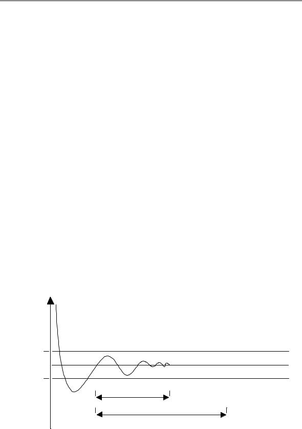
Position tolerance
The position tolerance is the threshold within which the axis must position at motion end. If the axis is out of tolerance, the move is not considered terminated.
When a move ends, if the position control is active, the system checks that all the axes are in the programmed position and that their lagging error (Le) is smaller than the threshold configured in the "in position band" field.
To enhance the positioning accuracy, the "in position band" threshold must remain active during an interval specified in the "in position window" field. If it does not, or if the positioning error is out of tolerance after the interval specified in the "in position time-out", the system generates an emergency condition.
lagging
error
in position |
t |
|
band
in position window
in position time-out
10 Series CNC - AMP Software Characterization Manual (10) |
1-5 |
Chapter 1
General Concepts
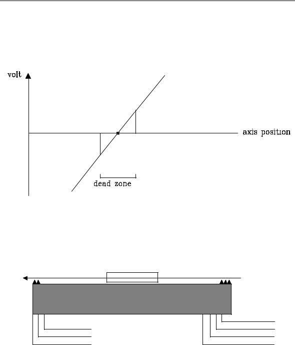
Dead zone
It is the threshold within which the D/A reference voltage output remains to zero irrespective of the position error.
The dead zone must be smaller than the position tolerance.
Travel limits
Each axis moves within the limits of an operating field, which is a function of the characteristics of the machine and can be established by means of physical and/or calculation devices which protect the axis from erroneous operation or loss of control.
o p e ra tin g lim it -
e n d o f tra v e l -
overtravel -
 +
+
o v er tra ve l+
end of travel+
o p e ra tin g lim it+
zero microswitch
The axis travel limits may be controlled by:
∙positive/negative end of travel microswitches
∙positive/negative end of travel microswitches
∙positive/negative operating limits
NOTE:
In many applications zero microswitch can be coincident with end of travel.
1-6 |
10 Series CNC - AMP Software Characterization Manual (10) |
Chapter 1
General Concepts
The microswitches start operating as soon as the machine is switched on whereas the operating limits, which are based on the axes positions, start operating only after the axes have been homed.
The overtravel microswitches are normally connected directly to the power circuitry of the axes.
In order to enable the travel microswitches that are connected to the I/O board they must be managed by the logic.
Operating limits are managed directly by the control. While the control executes a special cycle, such as tool or pallet change, the operating limits can be disabled or modified by the logic to allow displacements beyond the limits. Operating limits must be disabled/modified with standstill axes.
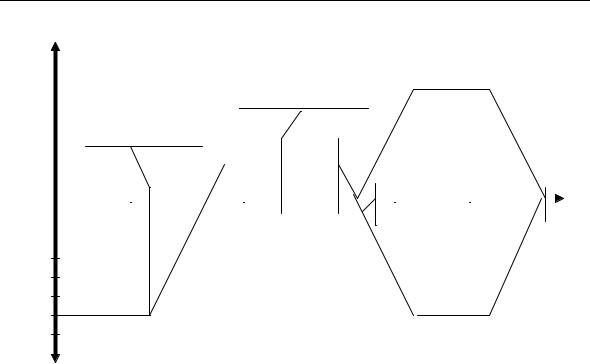
Homing cycle
Each time the system is switched on it is necessary to execute a homing cycle, i.e. to move the axes to the microswitch that is considered as the machine zero. The aim of this operation is to reset the internal counters that measure the axes positions. Axes home microswitch inputs are managed by the foreground logic, whose status can be read in status words SW03 and SW04 (refer to the "PLUS Application Manual").
This cycle is defined as home cycle.
I/O RIN G
M ODU LE
optical fiber
I/O C AR D
FOREGROUND
S W Ixx
The status of signals SW3 and SW4 must be interpreted as follows:
1= microswitch released
0= microswitch closed
10 Series CNC - AMP Software Characterization Manual (10) |
1-7 |

Chapter 1
General Concepts
To invert this operation mode it is necessary to write the NOT operator in the logic equations.
The homing cycle makes all the requests and signal controls that permit to refer the machine zero to the initial time.
A homing cycle can be broken down into four main steps:
1. Zero switch search
During this step the axis makes a linear displacement in search of the zero microswitch. As the contact with the microswitch occurs, the axis decelerates until it comes to a complete stop.
2. Zero switch release
n this step the axis reverts the direction of motion and moves until the zero microswitch is released. The return velocity is equal to the configured "home position feed" and cannot be altered by the "feed override".
3. Electric zero search
This step starts when the microswitch is released. The system waits for the electrical zero (i.e. marker ) to be read and then stops the axis.
4. Return to electric zero
After the system has acquired the coordinates in which the electrical zero was read, the axis is returned to the zero position.
If at cycle start the microswitch is already closed, the system will carry out only the last three steps. If the axis is configured with an optical linear scale, the microswitch is assumed to be missing and 1only the last two steps will be carried out: in this case the electrical zero switch search speed will be the one used in manual mode.
The homing cycle will be interrupted if the system is reset or put on hold. To resume the cycle a CYCLE START command must be given.
1-8 |
10 Series CNC - AMP Software Characterization Manual (10) |
Chapter 1
General Concepts
F + |
|
|
|
|
|
|
|
|
|
|
|
|
|
|
|
|
|
|
|
|
|
|||||||||
|
|
|
|
|
|
|
|
|
|
|
|
" h o m e l i m it s w it c h |
|
|
|
|
+ "m anu al" f eed |
|||||||||||||
|
|
|
|
|
|
|
|
|
|
|
|
|
|
|||||||||||||||||
|
|
|
|
|
|
|
|
|
|
|
|
r e l e a s e d " d e t e c te d |
b y |
|
||||||||||||||||
|
|
|
|
|
|
|
|
|
|
|
|
P . L . U . S . a n d |
|
|
|
|
|
|
|
|
|
|
|
|
||||||
|
|
|
|
|
|
|
|
|
|
|
|
|
|
|
|
|
|
|
|
|
|
|||||||||
|
|
|
" h o m e li m i t s w it c h |
|
|
n o ti fi e d t o t h e s y s t e m |
|
|
|
|
|
|
|
|
|
|||||||||||||||
|
|
|
|
|
|
|
|
|
|
|
|
|
|
|
|
|
|
|
|
|
|
|
|
|||||||
|
|
|
p r e s s e d " d e t e c t e d b y |
|
|
|
|
|
|
|
|
|
|
|
|
|
|
|
|
|
|
|
|
|
||||||
|
|
|
P . L . U . S . a n d |
|
|
|
|
|
|
|
m a rk er |
|
|
|
|
|
|
|
|
|
||||||||||
|
|
|
|
|
|
|
|
|
|
|
|
|
|
|
|
|
|
|
||||||||||||
|
|
|
n o t i fi e d to th e s y s te m |
|
|
|
|
|
|
|
|
|
|
|
|
|
|
|
|
|||||||||||
|
|
|
|
|
|
|
|
|
|
|
|
|
|
|
|
|
|
|
|
|
|
|
|
|||||||
|
|
|
|
|
|
|
|
|
|
|
"h om e fe ed" |
|
|
|
|
|
|
|
|
|
|
|
|
|||||||
|
|
|
|
|
|
|
|
|
|
|
|
|
|
|
|
|
|
|
|
|
|
|
|
|
|
|
|
|
|
|
|
|
|
|
|
|
|
|
|
|
|
|
|
|
|
|
|
|
|
|
|
|
|
|
|
|
|
|
|
|
|
O |
|
|
|
|
|
|
|
|
|
|
|
|
|
|
|
|
|
|
|
|
|
|
|
|
|
|
|
|
|
|
|
|
|
|
|
|
|
|
|
|
|
|
|
|
|
|
|
|
|
|
|
|
|
|
|
|
|
|
|
t |
|
|
|
|
|
|
|
|
|
|
|
|
|
|
|
|
|
|
AX IS H O M E D |
|
|
|
|
|
A X IS H O M E D |
|||||||
|
|
|
|
|
|
|
|
|
|
|
|
|
|
|
|
|
|
|
|
|
|
|||||||||
|
|
|
|
|
|
|
|
|
|
|
|
|
|
|
|
|
w /o |
nu ll offs e t |
|
|
|
|
|
w ith nu ll offs e t |
||||||
|
|
|
|
|
|
|
|
|
|
|||||||||||||||||||||
" m a nua l fe ed " |
- "m anu al" feed |
F -
Manual/automatic switch search
The switch search can be carried out manually or automatically. The "homing cycle type" field permits to define the switch search mode to be used in the homing cycle for each process.
Manual switch search
The characteristics of the manual switch search cycle to be carried out by the process axes are as follows:
1.prior to starting the cycle the operator must check that the selected direction of motion is compatible with the configured direction.
2.during the first step, i.e. while the axes are moving towards the microswitch, the operator must not release the CYCLE START pushbutton. If the command is to be sent by the logic, this means that no CYCLE STOP command must be given.
3.after the microswitch has been found the homing cycle will be completed even if the CYCLE START pushbutton is released and unless a RESET or HOLD command is given.
Automatic switch search
The characteristics of the automatic switch search cycle are:
1.the direction of motion is automatically selected by the control.
2.after the homing cycle has been launched, the operator can release the CYCLE START pushbutton. The cycle will be completed unless a RESET or HOLD command is given.
10 Series CNC - AMP Software Characterization Manual (10) |
1-9 |

Chapter 1
General Concepts
Miscellaneous axis parameters
10 Series CNC also allows characterization of the following axis parameters:
1. null offset |
corrects the position of the zero microswitch |
2. home position |
defines a machine zero that is independent from both the physical |
|
position of the zero microswitch and the actual axes displacement. |
|
|
|
|
|
|
|
|
|
|
c (machine zero) |
|
|
|
home |
|
|
|
|
|
|
|
||
|
|
|
|
|
|
position |
|
|
|
|
|
|
|
|
|
|
b (theoretical home switch) |
|
|
|
null |
||
|
|
|
|
|
|
offset |
|
|
|
|
|
|
|
|
|
a (physical home switch) |
|
|
|
|
|
||
The positions shown in the figure are as follows:
a)physical position of the zero microswitch
b)theoretical position of the zero microswitch
c)machine zero referred to the theoretical machine zero with respect to which all the other axis position parameters are defined.
The examples that follow show how to use these parameters:
correct microswitch position |
null offset = 0 |
machine zero on the zero microswitch |
home position = 0 |
a=b=c
absolute |
|
|
100 |
|||||
0 |
||||||||
positio n |
|
|||||||
|
|
|
|
|
|
|
||
|
|
|
|
|
|
|
|
|
|
100 |
|||||||
tran sd ucer |
0 |
|||||||
plane
physical ho me switch
theoretical
mach ine ze ro
1-10 |
10 Series CNC - AMP Software Characterization Manual (10) |

|
|
|
|
|
|
|
|
|
|
|
|
|
|
|
|
|
|
|
|
|
|
|
|
|
|
|
|
|
|
|
Chapter 1 |
||
|
|
|
|
|
|
|
|
|
|
|
|
|
|
|
|
|
|
|
|
|
|
|
|
|
General Concepts |
||||||||
|
|
|
|
|
|
|
|
|
|
|
|
|
|
|
|
|
|
|
|
|
|
|
|
|
|
|
|
|
|
|
|
|
|
microswitch position error |
|
|
|
|
|
|
|
|
null offset = +5 |
||||||||||||||||||||||||
machine zero on the microswitch |
|
|
|
|
|
|
|
|
home position = 0 |
||||||||||||||||||||||||
|
|
|
|
a=c |
|
|
|
|
b |
|
|
|
|
|
|
|
|
|
|
|
|||||||||||||
a bso lu te |
|
|
|
|
|
|
|
|
|
|
|
|
|
|
|
|
|
|
|
|
|
100 |
|
|
|||||||||
|
|
|
|
|
|
|
|
|
|
|
|
|
|
|
|
|
|
|
|
|
|
|
|||||||||||
p osition |
|
-5 |
|
|
|
|
|
|
|
|
|
|
0 |
|
|
|
|
||||||||||||||||
|
|
|
|
|
|
|
|
|
|
|
|
|
|
|
|
|
|
|
|
|
|
|
|
|
|
|
|
|
|
|
|
|
|
|
|
|
|
|
|
|
|
|
|
|
|
|
|
|
|
|
|
|
|
|
|
|
|
|
|
|
|
|
|
|
|||
transducer |
|
|
|
|
|
0 |
|
|
|
|
|
|
|
|
|
|
5 |
|
|
+105 |
|
|
|||||||||||
p lan e |
|
|
|
|
|
|
|
|
|
|
|
|
|
|
|
|
|
|
|
|
|
|
|
|
|
|
|
|
|
|
|
|
|
|
|
|
|
|
|
|
|
|
|
|
|
|
|
|
|
|
|
|
|
|
|
|
|
|
|
|
|
|
|
|
|
||
|
|
|
|
|
|
|
|
|
|
|
|
|
|
|
|
|
|
|
|
|
|
|
|
|
|
|
|
|
|
|
|
||
|
|
|
|
|
|
|
|
|
|
|
|
|
|
|
|
|
|
|
|
|
|
|
|
|
|
|
|
|
|
|
|
|
|
|
|
|
|
|
|
|
|
|
|
|
|
null offset |
|
|
|
|
|
|
|
|
|
|
|
|
|
|
|
|
|
|
|
||
|
|
|
|
|
|
|
|
|
|
|
|
|
|
|
|
|
|
|
|
|
|
|
|
|
|
|
|
|
|
|
|||
|
|
|
|
|
|
|
|
|
|
|
|
|
|
|
|
|
|
|
|
|
|
|
|
|
|
|
|
|
|
|
|||
|
|
p hysical hom e switch |
theo re tical |
|
|
|
|
|
|
|
|
|
|
|
|||||||||||||||||||
|
|
|
|
|
|
|
|
|
|
|
|
|
|
|
m achin e zero |
|
|
|
|
|
|
|
|
|
|
|
|||||||
no microswitch position error |
|
|
|
|
|
|
|
|
null offset = 0 |
||||||||||||||||||||||||
offset between machine zero and physical microswitch |
home position = +100 |
||||||||||||||||||||||||||||||||
|
|
|
a=b |
|
|
|
|
|
|
|
|
|
|
|
c |
||||||||||||||||||
|
|
|
|
|
|
|
|
|
|
|
|
|
|
|
|
|
|
|
|
|
|
|
|
|
|
||||||||
a bso lu te |
|
|
|
|
|
|
|
|
|
|
|
|
|
|
|
|
|
|
|
|
|
|
|
|
|
|
|
|
|
|
|
|
|
|
|
|
|
|
|
|
|
|
|
|
|
|
|
|
|
|
|
|
|
|
|
|
|
|
|
|
|
|
|
|
|
||
p osition |
|
-100 |
|
|
|
|
|
|
|
|
|
|
|
|
|
|
|
|
|
0 |
|
|
|
|
|
||||||||
|
|
|
|
|
|
|
|
|
|
|
|
|
|
|
|
|
|
|
|
|
|
|
|
|
|
|
|
|
|
|
|
|
|
|
|
|
|
|
|
|
|
|
|
|
|
|
|
|
|
|
|
|
|
|
|
|
|
|
|
|
|
|
|
||||
|
|
0 |
|
|
|
|
|
|
|
|
|
|
|
|
|
|
|
|
|
|
|
||||||||||||
transd ucer |
|
|
|
|
|
|
|
|
|
|
|
|
|
|
|
|
|
|
|
100 |
|
|
|
|
|||||||||
pla ne |
|
|
|
|
|
|
|
|
|
|
|
|
|
|
|
|
|
|
|
|
|
|
|
|
|
|
|
|
|
|
|
|
|
|
|
|
|
|
|
|
|
|
|
|
|
|
|
|
|
|
|
|
|
|
|
|
|
|
|
|
|
|
|
|
|
|
|
|
|
|
|
|
|
|
|
|
|
|
|
|
|
|
|
|
|
|
|
|
|
|
|
|
|
|
|
|
|
|
|
|
|
|
|
|
|
|
|
|
|
|
|
|
|
|
|
|
|
|
|
|
|
|
|
|
|
|
|
|
|
|
|
|
|
||
|
|
|
|
|
|
|
|
|
|
|
|
|
|
|
home position |
|
|
|
|
|
|
|
|
|
|
|
|||||||
|
|
|
|
|
|
|
|
|
|
|
|
|
|
|
|
|
|
|
|
|
|||||||||||||
|
|
|
|
|
|
|
|
|
|
|
|
|
|
|
|
|
|
|
|
|
|
|
|||||||||||
|
p hysical hom e switch |
|
|
|
|
|
|
|
|
|
machine ze ro |
||||||||||||||||||||||
|
|
|
the oretical |
|
|
|
|
|
|
|
|
|
|
|
|
|
|
|
|
|
|
|
|||||||||||
microswitch position error |
|
|
|
|
|
|
|
|
null offset = +5 |
||||||||||||||||||||||||
offset between the machine zero and the zero microswitch |
home position = +100 |
||||||||||||||||||||||||||||||||
|
|
|
|
a |
|
|
b |
|
|
|
|
c |
|||||||||||||||||||||
a bsolu te |
|
|
|
|
|
|
|
|
|
|
|
|
|
|
|
|
|
|
|
|
|
|
|
|
|
|
|
|
|
|
|
|
|
|
|
|
|
|
|
|
|
|
|
|
|
|
|
|
|
|
|
|
|
|
|
|
|
|
|
|
|
|
|
|
|
||
-105 |
|
|
|
|
|
|
-100 |
|
|
0 |
|
|
|
|
|
||||||||||||||||||
p osition |
|
|
|
|
|
|
|
|
|
|
|
|
|
|
|||||||||||||||||||
|
|
|
|
|
|
|
|
|
|
|
|
|
|
|
|
|
|
|
|
|
|
|
|
|
|
|
|
|
|
|
|
|
|
|
|
|
|
|
|
|
|
|
|
|
|
|
|
|
|
|
|
|
|
|
|
|
|
||||||||||
tran sducer |
0 |
|
|
|
|
|
|
|
|
5 |
|
|
|
+105 |
|
|
|
||||||||||||||||
p lan e |
|
|
|
|
|
|
|
|
|
|
|
|
|
|
|
|
|
|
|
|
|
|
|
|
|
|
|
|
|
|
|
|
|
|
|
|
|
|
|
|
|
|
|
|
|
|
|
|
|
|
|
|
|
|
|
|
|
|
|
|
|
|
|
|
|
||
|
|
|
|
|
|
|
|
|
|
|
|
|
|
|
|
|
|
|
|
|
|
|
|
|
|
|
|
|
|
|
|
||
|
|
|
|
|
|
|
|
|
|
|
|
|
|
|
|
|
|
|
|
|
|
|
|
|
|
|
|
|
|
|
|
|
|
|
|
|
|
|
|
|
|
|
|
|
|
null offset |
|
|
|
|
|
|
|
|
|
home position |
|
|
|
||||||||
|
|
|
|
|
|
|
|
|
|
|
|
||||||||||||||||||||||
|
|
|
|
|
|
|
|
|
|
|
|
|
|
||||||||||||||||||||
|
physical ho me switch |
the oretical |
|
|
ma chine zero |
||||||||||||||||||||||||||||
10 Series CNC - AMP Software Characterization Manual (10) |
1-11 |

Chapter 1
General Concepts
Operating limits
The operating limits are defined with respect to the machine zero (c) in the AMP.
Measuring cycle
The coordinates read by the axes boards are referred to the machine zero (c).
Coordinate display modes
10 Series CNC permits the display of the following axis coordinates:
Absolute coordinates |
referred to the machine zero (c) |
Machine coordinates |
referred to the machine zero (c) and including the origins |
Work coordinates |
programmed coordinates |
Distance to go |
difference between programmed and machine coordinates |
Error |
difference between interpolated and real coordinates |
The example that follows illustrates an axes calibration sequence.
1.Set the "null offset" and "home position" fields in the AMP to zero.
2.Key in the corrections to the geometrical errors in the AMP. This corrections are based on the mecahnical distances to the physical microswitch.
3.Switch off and reboot the control.
4.Home the axis.
5.Move the axis to the position in which the zero microswitch should have been wired.
6.With the axis in this position read the "absolute position" coordinate.
7.Write this value in the "null offset" AMP field for the axis in object.
8.If the home position is to be established on a value other than zero, write this value in the "home position" AMP field for the axis in object.
9.Switch off and reboot the control.
10.From this point, all the machine coordinates are measured with respect to the "machine zero".
11.If necessary, define the operating limits in the AMP. These limits are always referred to the "machine zero".
1-12 |
10 Series CNC - AMP Software Characterization Manual (10) |
Chapter 1
General Concepts
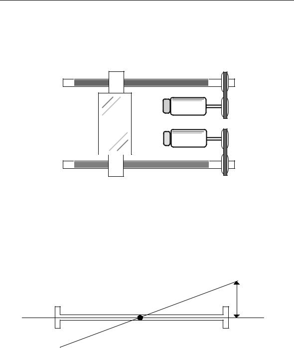
SPLIT AXES
A split axis (gantry) is a physical axis coupled to a pair of motors or drives. Split axes are typical of large machines and of machines with special mechanical requirements, such as
From the User's standpoint, a split axis is seen as one single axis configured as a Master.
Servo motor 1
Axis
Servo motor 2
The parameters that configure a split axis are:
SKEW |
It is the maximum acceptable disalignment between two physical axes. Two |
|
maximum values are configured: the first one (Max Skew Error) is used both |
|
during movement for non referred axes and during the marker search; the second |
|
(Skew Error) is used for all other movements for referred axes and after the marker |
|
search. |
|
When the current skew error exceeds the configured value, an emergency |
|
condition (Skew Error) occurs. |
SKEW GAIN |
permits to specify the skew compensation value. |
S K E W
When the split axis is enabled, the system calculates at each sampling the lagging errors of the master (Lem = Lagging Error Master) and the slave (Les = Lagging Error Slave).
The misalignement (SKEW) can be calculated as follows:
SKEW = Lem - Les
10 Series CNC - AMP Software Characterization Manual (10) |
1-13 |

Chapter 1
General Concepts
The result of multiplying the SKEW value by the SKEW GAIN can be used for calculating new lagging errors with the folllowing formulas:
Lem' = Lem + (Skew Gain * (Skew/2 ) )
Les' = Les - (Skew Gain * (Skew/2) )
If these new lagging errors are multiplied by a K constant, the resulting voltages on the D/A converter represent positive and negative skew compensations to be applied to the master and the slave.
Such compensation tends to re-align the axes correctly.
In case of emergencies (servo, error, skew error ...) and of all operations generating disabling and abling of a couple of split axes, it is necessary to refer the axes again in order to ensure correct application of configured null offset and home position parameters and recuperate the misalignment between the two physical axes that the activation/deactivation condition may have generated.
The figure illustrates how the wiring and/or the mechanical orientation permit to shift the counting direction of the position transducer or the rotation of the motor between the master and the slave. (T=transducer, M=motor)
MASTER |
SLAVE |
T |
T |
M |
M |
MASTER |
SLAVE |
T |
T |
M |
M |
1-14 |
10 Series CNC - AMP Software Characterization Manual (10) |
Chapter 1
General Concepts
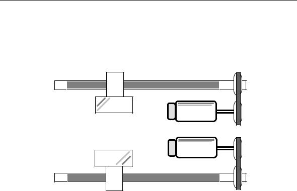
DUAL AXES
Dual axes are two or more axes that follow an identical trajectory. A typical application of this feature are multiple heads and multi-spindles.
Servo motor 1
Axis 1
Servo motor 2
Axis 2
With dual axes, only the programming of the master axis is mandatory.
The master-slave association must be defined by the program (refer to the UDA instruction in the Programming Guide).
10 Series CNC - AMP Software Characterization Manual (10) |
1-15 |
Chapter 1
General Concepts
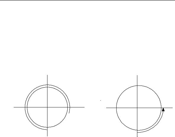
AXES WITH ROLLOVER
The axes with rollover are linear or rotary axes whose position is controlled by the system within a range from zero to the value configured in the "Rollover pitch" field.
The sign of the quote programmed for the axis with rollover indicates the rotation direction:
∙positive, rotation is in a clockwise direction
∙negative, rotation is in an anticlockwise direction.
Examples:
270
180 |
359.999 |
0 |
 0
0
90
CLOCKWISE
ROTATION ANTICLOCKWISE ROTATION
1-16 |
10 Series CNC - AMP Software Characterization Manual (10) |
Loading...