

Page 1

10 Series CNC
User Manual
Code: 45004452H
Rev. 15
PUBLICATION ISSUED BY:
OSAI S.p.A.
Via Torino, 14 - 10010 Barone Canavese (TO) – Italy
Tel. +39-0119899711
Web: www.osai.it
e-mail: sales@osai.it
service@osai.it
Copyright 2001-2004 by OSAI
All rights reserved
Edition:November 2004
IMPORTANT USER INFORMATION
This document has been prepared in order to be used by OSAI. It describes the latest release of
the product.
OSAI reserves the right to modify and improve the product described by this document at any time
and without prior notice.
Actual application of this product is up to the user. In no event will OSAI be responsible or liable for
indirect or consequential damages that may result from installation or use of the equipment
described in this text.
Page 2

abc
Page 3

UPDATE
10 Series CNC User Manual
SUMMARY OF CHANGES
General
This publication is issued with reference to Software Release 7.4 for the 10 Series systems (E69).
The following modifications have been made to this revision.
PAGES UPDATE TYPE
INDEX
Chapter 2
page 10 Added new description: PLUS SD000
Chapter 3
page 47 Added description of softkey: SYSTEM SHUT DOWN
Chapter 11
page 8
Appendix A
page 25 Added new codes: SD214-SD215-SD216-SD217
Updated
Added new description: Execution of paramacros in MDI mode
10 Series CNC User Manual (15)
Page 4

abc
abc
Page 5

Preface
10 Series CNC User Manual
PREFACE
This manual describes how to operate a 10 Series CNC. It provides the end user with all the
necessary information for using and programming the system.
REFERENCE
Consult:
• 10 Series CNC Product Specifications
• 10 Series CNC AMP - Software Characterisation Manual
For further information refer to:
• 10 Series CNC Programming Manual
SUMMARY
This manual describes how your 10 Series CNC works and explains how to operate the system.
Each chapter deals with a separate topic.
1. Features and specifications
This chapter lists the general hardware and software characteristics of 10 Series CNC’s. It also
describes the major features of the front panel.
2. System start up
This chapter explains how to switch an and start up the system. It discusses the screens and
messages displayed when the system runs the self diagnostic.
3. User interface
This chapter describes the function of the softkeys, pushbuttons and controls available on the
panel. An overview of all the softkeys levels available gives the user a reference guide of all the
softkeys available. It provides a detailed description of the various video pages and discusses
the optional operator console.
10 Series CNC User Manual (09) 1
Page 6

Preface
10 Series CNC User Manual
4. Setting system variables and parameters
This chapter explains how to set the local and system variables used for program writing. It also
describes how to set the machine operation parameters accessible with the MACHINE SET UP
softkey.
5. Establishing origins and homing the axes
This chapter describes how to home the axes and establish the machine origins. In addition, it
provides a definition of the various reference and origin points managed by the control.
6. Axes jogging and stop function
This chapter describes how to move the axes manually.
7. Using tables
This chapter deals with the tables controlled by the system. It describes the Table Editor, a
utility with which to compile and edit system tables.
8. Table editor configurator
This chapter deals with the Table Editor, a utility for customising the tables visualised or printed
by the system, the video pages and the softkey labels. It also discusses how to configure and
handle customised tables.
9. Tool management
This chapter explains how to define tool offsets and part origins an the spindle axis. In addition
it describes how to manage the information stored in the Tool Data Base (tool mounting,
transfer, etc.).
10. Part program file manager
The chapter describes the part program management environment, the directories display, the
copy, rename and edit of the part programs.
11. Part program execution
This chapter explains how to set the machine for part program execution as well as the various
execution modes.
12. Machine Plot
This chapter introduces the MACHINE PLOT, a utility with which to visualise the tool path
graphics in real time while the machine is executing the program.
13. DOS Shell
This chapter describes the procedures for hard disk file management using the DOS operating
system functions.
2 10 Series CNC User Manual (09)
Page 7

Preface
10 Series CNC User Manual
14. Security
This chapter describes a series of security functions that regulate the access to the system
resources.
15. Peripherals
This chapter describes the programs used to configure and use the systems with
communication ports connected to external devices (via a serial, parallel or Ethernet line).
16. Ethernet Communication
This chapter provides the most important information about Ethernet communication and
describes how to configure the network and the network services.
17. Function tables
Lists the enabling tables.
A. Error messages
Lists the error codes and messages and the related recovery operations.
10 Series CNC User Manual (09) 3
Page 8
Preface
10 Series CNC User Manual
Warnings
For correct control operation, it is important to follow the information given in this manual. Take
particular care with topics bearing one of the mentions: WARNING, CAUTION or IMPORTANT,
which indicate the following types of information:
Draws attention to facts or circumstances that may cause damage to the
WARNING
control, to the machine or to operators.
CAUTION
IMPORTANT
Indicates information to be followed in order to avoid damage to equipment
in general.
Indicates information that must be followed carefully in order to ensure full
success of the application.
Terminology
Some terms appearing throughout the manual are explained below.
Control Refers to the 10 Series numerical control unit comprising front panel unit and
basic unit.
Front Panel Is the interface module between machine and operator; it has a monitor on
which messages are output and a keyboard to input the data. It is connected to
the basic unit.
Basic Unit Is the hardware-software unit handling all the machine functions. It is connected
to the front panel and to the machine tool.
END OF PREFACE
4 10 Series CNC User Manual (09)
Page 9

10 Series CNC User Manual
INDEX
FEATURES AND SPECIFICATIONS
INTRODUCTION ............................................................................................................. 1-1
Processes .............................................................................................................. 1-1
HARDWARE STRUCTURE ............................................................................................ 1-2
Central Unit............................................................................................................ 1-2
Operator Panel ...................................................................................................... 1-4
WINMEDIA....................................................................................................................... 1-7
General .................................................................................................................. 1-7
Mass storage ......................................................................................................... 1-14
FDU peripheral ...................................................................................................... 1-14
CD-ROM peripheral............................................................................................... 1-14
Keyboard connection............................................................................................. 1-14
Mouse connection.................................................................................................. 1-14
Ethernet connection............................................................................................... 1-14
Riser Card.............................................................................................................. 1-14
External connections ............................................................................................. 1-14
Keyboard ............................................................................................................... 1-15
Operator Console .................................................................................................. 1-16
SOFTWARE STRUCTURE ............................................................................................. 1-18
Utilities ................................................................................................................... 1-20
Index
SYSTEM START UP
SYSTEM POWER UP...................................................................................................... 2-1
DIAGNOSTIC SCREENS................................................................................................ 2-1
Modules ................................................................................................................. 2-4
EMERGENCY SYSTEM SWITCH-ON ............................................................................ 2-5
DIAGNOSTIC MESSAGES............................................................................................. 2-7
PASSED Tests ...................................................................................................... 2-8
REPORTS about devices and actions in progress ............................................... 2-9
Error messages ..................................................................................................... 2-10
USER INTERFACE
KEYBOARD .................................................................................................................... 3-1
Function keys......................................................................................................... 3-2
Alphanumeric Section............................................................................................ 3-2
10 Series CNC User Manual (15) i
Page 10

Index
10 Series CNC User Manual
OPERATOR PANEL FUNCTION KEYS ......................................................................... 3-4
Fixed Keys ............................................................................................................. 3-4
Special keys ........................................................................................................... 3-5
CONTROL BUTTONS ..................................................................................................... 3-6
VIDEO ..............................................................................................................................3-7
Main screen............................................................................................................ 3-9
Status information area.......................................................................................... 3-10
Axes data area .......................................................................................................3-12
General data area .................................................................................................. 3-13
Part program data area.......................................................................................... 3-15
Large font display................................................................................................... 3-16
Configurable screen pages .................................................................................... 3-19
System status (SYS_STA) ..................................................................................... 3-20
Axes position (AXES_POS) ................................................................................... 3-22
Program display (PRG_DISP) ............................................................................... 3-23
Process status (PROC_STA)................................................................................. 3-24
Programmed code state (CODE_STA).................................................................. 3-26
Axes offsets (AXIS_OFF)....................................................................................... 3-27
Selecting a screen.................................................................................................. 3-27
Enlarging an elementary quadrant......................................................................... 3-28
Directory of Programs screen ................................................................................ 3-29
Additional data windows ........................................................................................ 3-30
General rules about data entry windows ...............................................................3-32
SOFTKEYS ...................................................................................................................... 3-35
Main menu .............................................................................................................3-38
Auto ........................................................................................................................ 3-39
Manual.................................................................................................................... 3-41
Part Program.......................................................................................................... 3-42
Variables ................................................................................................................3-43
OEM ....................................................................................................................... 3-43
Machine Set-Up .....................................................................................................3-44
Tables..................................................................................................................... 3-46
Diagnostics............................................................................................................. 3-47
Utility....................................................................................................................... 3-48
OPERATOR CONSOLE .................................................................................................. 3-49
Operator Console Keys and Functions.................................................................. 3-49
Pilot Panel Selectors and Functions ...................................................................... 3-52
Controls and functions of the WinMedia operator console .................................... 3-55
SETTING SYSTEM VARIABLES AND PARAMETERS
LOCAL AND SYSTEM VARIABLES ..............................................................................4-1
E variables ............................................................................................................. 4-2
User variables ........................................................................................................ 4-3
H variables ............................................................................................................. 4-4
SN variables........................................................................................................... 4-5
SC variables........................................................................................................... 4-6
PLUS variables ......................................................................................................4-9
Searching for pages and variable indexes............................................................. 4-10
Using variables for calculations .............................................................................4-11
SETTING MACHINE PARAMETERS.............................................................................. 4-12
Dynamic Params.................................................................................................... 4-13
Dynamic limits ........................................................................................................ 4-15
Program SET-UP ................................................................................................... 4-16
Block Retrace......................................................................................................... 4-16
ii 10 Series CNC User Manual (15)
Page 11

10 Series CNC User Manual
Probe parameters.................................................................................................. 4-17
Axes Reference ..................................................................................................... 4-18
Accuracy ................................................................................................................ 4-19
Time/date............................................................................................................... 4-20
ESTABLISHING ORIGINS AND HOMING THE AXES
GENERAL........................................................................................................................ 5-1
HOMING THE AXES ....................................................................................................... 5-3
Manual Homing ................................................................................................ 5-3
Automatic Homing ............................................................................................ 5-3
DEFINING ORIGINS........................................................................................................ 5-5
DEFINING THE PART ZERO ON THE SPINDLE AXIS................................................. 5-8
Part zero on tool tip................................................................................................ 5-8
Part zero on spindle nose...................................................................................... 5-10
HOMING AND ORIGIN PRESETTING FOR DIAMETER AXES.................................... 5-11
AXES JOGGING AND STOP FUNCTIONS
Index
JOG.................................................................................................................................. 6-1
Continuous Jog...................................................................................................... 6-2
Incremental Jog ..................................................................................................... 6-2
DEFINING THE JOG INCREMENT ................................................................................ 6-3
FEEDRATE OVERRIDE.................................................................................................. 6-4
ALTERING THE JOG INCREMENT ............................................................................... 6-5
JOG RETURN TO THE PROFILE .................................................................................. 6-6
SPINDLE SPEED OVERRIDE ........................................................................................ 6-7
STOP FUNCTIONS ......................................................................................................... 6-8
Reset...................................................................................................................... 6-8
Hold........................................................................................................................ 6-8
EMERGENCY STOP ....................................................................................................... 6-9
ACTIVE RESET............................................................................................................... 6-9
REMOVING THE TOOL AFTER AN EMERGENCY ...................................................... 6-12
USING TABLES
WHAT IS A TABLE? ....................................................................................................... 7-2
USING THE TABLE EDITOR.......................................................................................... 7-3
Directory Window................................................................................................... 7-5
Softkeys common to all Tables.............................................................................. 7-6
Table Editor Keys .................................................................................................. 7-7
TABLE EDITOR FUNCTIONS ........................................................................................ 7-8
Opening a Table .................................................................................................... 7-8
Loading a Table ..................................................................................................... 7-9
Altering a Table...................................................................................................... 7-10
Incremental Parameter Modification...................................................................... 7-11
Inserting a Record in a Table ................................................................................ 7-12
Canceling a Record from a Table.......................................................................... 7-13
Saving a Table....................................................................................................... 7-14
Printing a Table...................................................................................................... 7-14
Sorting Lines and Columns ................................................................................... 7-15
Search for an Element........................................................................................... 7-16
Changing the Measuring Unit ................................................................................ 7-16
10 Series CNC User Manual (15) iii
Page 12

Index
10 Series CNC User Manual
Table Backup ......................................................................................................... 7-17
Restoring Tables .................................................................................................... 7-18
ORIGINS TABLE ............................................................................................................. 7-19
TOOLS TABLE ................................................................................................................ 7-21
TOOL OFFSETS TABLE................................................................................................. 7-26
TOOL DATA BASE .........................................................................................................7-29
MAGAZINE TABLE ......................................................................................................... 7-32
USER TABLE .................................................................................................................. 7-32
TABLE EDITOR CONFIGURATOR
GENERAL........................................................................................................................ 8-1
CONFIGURATOR SCREENS ......................................................................................... 8-2
Main configurator screen ....................................................................................... 8-2
Configurator screen ............................................................................................... 8-3
SOFTKEYS ...................................................................................................................... 8-7
Softkeys in the main configurator screen............................................................... 8-7
Configuration screen softkeys single tables ..........................................................8-8
LOADING A CONFIGURATION FILE............................................................................. 8-10
SAVING A CONFIGURATION ........................................................................................8-11
RESTORING THE DEFAULT CONFIGURATION .......................................................... 8-12
AXES CONFIGURATION ................................................................................................ 8-13
CONFIGURING A TABLE ............................................................................................... 8-14
Configuring fields ...................................................................................................8-17
LINKING TABLE FIELDS................................................................................................ 8-20
UNLINKING TABLE FIELDS .......................................................................................... 8-22
ARRANGING THE TABLE FIELDS ................................................................................ 8-23
CONFIGURING THE PRINTING OUTPUT .....................................................................8-26
CONFIGURING HELP ..................................................................................................... 8-28
CONFIGURING SOFTKEYS ...........................................................................................8-29
QUITTING THE CONFIGURATOR ENVIRONMENT...................................................... 8-30
PERSONALISING USER TABLES ................................................................................. 8-31
User Table Manager screens and softkeys ........................................................... 8-32
Configuring a table ................................................................................................. 8-37
Configuring the table fields .................................................................................... 8-39
Copying a table or the fields of a table................................................................... 8-40
Copying a table ...................................................................................................... 8-40
Copying table fields................................................................................................ 8-41
Configuring HELP MESSAGES ............................................................................. 8-42
Loading and saving a table on a file ......................................................................8-43
Printing a user table ............................................................................................... 8-43
TOOL MANAGEMENT
GENERAL........................................................................................................................ 9-1
TOOL PRESETTING .......................................................................................................9-2
Tool presetting on an external system ................................................................... 9-3
Tool presetting on the machining part ................................................................... 9-4
DEFINING A MULTIPLE CUTTER TOOL....................................................................... 9-6
MANAGING THE TOOL DATA BASE ............................................................................ 9-7
Transfering tool data between the Tool Data Base and the Tool Table ................ 9-7
Entry of data fora new tool in the Tool Table (retrieved from Data Base) .............9-7
Overwriting the data of a tool already in the Tool Table with the Data Base data. 9-9
iv 10 Series CNC User Manual (15)
Page 13

10 Series CNC User Manual
PART PROGRAM FILE MANAGER
Main screen ........................................................................................................... 10-1
SOFTKEYS...................................................................................................................... 10-3
LINE EDITOR .................................................................................................................. 10-4
Line Editor screen.................................................................................................. 10-4
Creating a new part program................................................................................. 10-7
Loading an existing Part Program ......................................................................... 10-7
Loading a running Part Program ........................................................................... 10-7
Characteristics of the Line Editor........................................................................... 10-8
Line Editor function keys ....................................................................................... 10-9
Writing new characters in a block.......................................................................... 10-11
Opening a new line ................................................................................................ 10-11
Deleting lines ......................................................................................................... 10-12
Retrieving lines ...................................................................................................... 10-13
Configuration Editor............................................................................................... 10-14
Numbering program blocks ................................................................................... 10-16
Search for strings and block numbers................................................................... 10-17
Cut & Paste............................................................................................................ 10-18
Inserting a part program ........................................................................................ 10-20
Saving a part program ........................................................................................... 10-20
Index
PART PROGRAM EXECUTION
SETTING PART PROGRAM PARAMETERS ................................................................ 11-1
EXECUTION OF A PART PROGRAM............................................................................ 11-4
Selecting and activating a part program................................................................ 11-4
Automatic execution .............................................................................................. 11-4
Semiauto (block-by-block) execution .................................................................... 11-5
Multiblock retrace................................................................................................... 11-6
Executing blocks from keyboard............................................................................ 11-7
MDI execution without an active part program ...................................................... 11-7
MDI execution with an active part program ........................................................... 11-8
Executing part of a program .................................................................................. 11-9
Modifying blocks in BLK/BLK mode....................................................................... 11-10
Restoring a part program....................................................................................... 11-10
Search for a string ................................................................................................. 11-11
Overriding the programmed feedrate .................................................................... 11-12
Overriding the spindle speed................................................................................. 11-13
Overriding the rapid ............................................................................................... 11-14
Execution in Dry Run mode................................................................................... 11-14
MEMORY SEARCHING .................................................................................................. 11-15
Automatic searching .............................................................................................. 11-15
Searching for a pre-set block................................................................................. 11-16
Restarting a working cycle..................................................................................... 11-16
Searching mode..................................................................................................... 11-17
MACHINE PLOT
MACHINE PLOT USED WITH AXES CONNECTED ..................................................... 12-1
User interface with axes connected ...................................................................... 12-2
Machine Plot video page with axes connected ..................................................... 12-3
Softkeys active in axes connected mode .............................................................. 12-4
SETTING MACHINE PLOT PARAMETERS WITH AXES CONNECTED ..................... 12-5
10 Series CNC User Manual (15) v
Page 14

Index
10 Series CNC User Manual
DRAWING A PROFILE WITH CONNECTED AXES ......................................................12-9
CHECKING THE GRAPHICS.......................................................................................... 12-10
ZOOM............................................................................................................................... 12-11
CAPTURING POINT COORDINATES ............................................................................ 12-13
MACHINE PLOT WITH AXES DISCONNECTED (DRY RUN MODE) ........................... 12-15
Configuration and functionality in use with axes disconnected .............................12-15
Video page with axes disconnected (Dry Run Active)........................................... 12-16
Softkeys active in axes disconnected mode (dry run) ...........................................12-17
SETTING THE MACHINE PLOT PARAMETERS WITH AXES DISCONNECTED 12-18
VERIFY............................................................................................................................. 12-21
CLEAR SCREEN ............................................................................................................. 12-21
EXAME GRAPHIC ........................................................................................................... 12-21
DOS SHELL
LAUNCHING DOS SHELL .............................................................................................. 13-1
DEFAULT PARAMETER VALUES ................................................................................. 13-2
DISPLAYING A DIRECTORY ......................................................................................... 13-4
DOS SHELL COMMANDS .............................................................................................. 13-6
ABORT................................................................................................................... 13-7
BACKUP................................................................................................................. 13-7
COPY ..................................................................................................................... 13-8
DELETE .................................................................................................................13-9
DIRECTORY ..........................................................................................................13-10
EDIT ....................................................................................................................... 13-11
EXIT .......................................................................................................................13-11
FORMAT ................................................................................................................ 13-12
HELP ...................................................................................................................... 13-13
MKDIR.................................................................................................................... 13-14
PRINT..................................................................................................................... 13-15
RENAME................................................................................................................ 13-16
RESTORE.............................................................................................................. 13-17
SHOW DRIVES...................................................................................................... 13-18
XCOPY................................................................................................................... 13-19
SECURITY
USER LEVELS................................................................................................................. 14-2
ABILITY TO USE SYSTEM FUNCTIONS .......................................................................14-3
ABILITY TO INSTALL OPTIONS.................................................................................... 14-4
ENABLING THE SECURITY ENVIRONMENT ...............................................................14-5
SET LEVEL ............................................................................................................ 14-6
SET PASSWORD .................................................................................................. 14-7
SET SECURITY ..................................................................................................... 14-8
SHOW SECURITY................................................................................................. 14-10
PRODUCT INFO.................................................................................................... 14-11
PRODUCT KEYS................................................................................................... 14-11
INSTALL................................................................................................................. 14-12
SHOW OPTION and SHOW FIXUPS.................................................................... 14-13
PERIPHERALS
ACTIVATING PERIPHERALS........................................................................................ 15-2
vi 10 Series CNC User Manual (15)
Page 15

10 Series CNC User Manual
INTERLNK....................................................................................................................... 15-3
Configuration ......................................................................................................... 15-3
Interlnk Configuration for 10 Series System.......................................................... 15-3
Interlnk Configuration Personal Computer ............................................................ 15-7
PRINT DEVICE................................................................................................................ 15-8
REMOTE BOOT .............................................................................................................. 15-9
ETHERNET COMUNICATION
INTRODUCTION ............................................................................................................. 16-1
COMMENTS ON THE NETWORKS ............................................................................... 16-3
Definitions .............................................................................................................. 16-3
Network topology................................................................................................... 16-5
CONFIGURATION OF THE NETWORK ........................................................................ 16-7
General view.......................................................................................................... 16-7
Network configurator ............................................................................................. 16-7
FUNCTIONS OFFERED BY THE NETWORK................................................................ 16-8
File Transfer........................................................................................................... 16-8
Server services ...................................................................................................... 16-8
Access from a client............................................................................................... 16-9
Exchanges of messages between tasks ............................................................... 16-9
USER INTERFACE ......................................................................................................... 16-12
Access to the configuration environment .............................................................. 16-12
Network configurator screen displays ................................................................... 16-13
Main screen ...................................................................................................... 16-13
First screen display: Advanced Level............................................................... 16-13
Second screen display ..................................................................................... 16-14
Third screen display (optional) ......................................................................... 16-16
NETWORK CONFIGURATOR SOFTKEYS ................................................................... 16-18
Level selection (LEVEL Softkey) ........................................................................... 16-20
Channel configuration (CHAN GENERAL Softkey) .............................................. 16-20
Configuration of server type services (SERVER Softkey)..................................... 16-22
Configuration of client type services (CLIENT Softkey) ........................................ 16-24
CONFIGURATION OF TASK-TO-TASK TYPE SERVICES .......................................... 16-26
Enabling Task-To-Task communication ................................................................ 16-26
Defining a local environment as sharable in the network (SHARED ENV
softkey) .................................................................................................................. 16-26
Connection to a remote environment (REMOTE ENV. Softkey)........................... 16-28
Immediate connection of remote environments (Softkey ENVIR. CONNECT)..... 16-30
Automatic connection of remote devices (Softkey SERVICES CONN.) ............... 16-31
USE OF THE SERVICES IN THE NETWORK................................................................ 16-32
Network activation on the 10 Series system ......................................................... 16-32
Enabling the net on a Windows PC ....................................................................... 16-32
ACCESS TO A SERVICE FROM DOS SHELL .............................................................. 16-33
Display of the drives .............................................................................................. 16-33
ACCESS TO A PART PROGRAM.................................................................................. 16-34
DOS REAL TIME ENVIRONMENT ................................................................................. 16-34
Index
FUNCTION TABLES
FUNCTION TABLES: BYTE 0 - Reserved ............................................................ 17-1
FUNCTION TABLES: BYTE 1 - Reserved ............................................................ 17-2
FUNCTION TABLES: BYTE 2 - Maintenance....................................................... 17-2
FUNCTION TABLES: BYTE 3 - Directory Protection............................................ 17-3
10 Series CNC User Manual (15) vii
Page 16

Index
10 Series CNC User Manual
FUNCTION TABLES: BYTE 4 - System Tables Protection................................... 17-3
FUNCTION TABLES: BYTE 5 - Configuration ......................................................17-4
FUNCTION TABLES: BYTE 6 - PLUS Execution.................................................. 17-4
FUNCTION TABLES: BYTE 7 - Part Program Development ................................ 17-5
FUNCTION TABLES: BYTE 8 - Execution of CNC Functions .............................. 17-5
FUNCTION TABLES: BYTE 9 - Reserved OEM ................................................... 17-6
ERROR MESSAGES
USER INTERFACE ERRORS ......................................................................................... A-2
PART PROGRAM ERROR MESSAGES ........................................................................ A-5
TABLE EDITOR ERRORS ..............................................................................................A-6
DOS SHELL ERROR MESSAGES ................................................................................. A-11
SECURITY ERRORS....................................................................................................... A-13
EMERGENCY MESSAGES............................................................................................. A-15
MESSAGES FOR D.S.I. ANOMALIES............................................................................ A-17
MESSAGES ON FASTWIRE ANOMALIES .................................................................... A-17
RESERVED MESSAGES ................................................................................................ A-17
HARDWARE DIAGNOSTICS ERRORS .........................................................................A-18
Base unit (main CPU) ............................................................................................A-18
Other boards .......................................................................................................... A-19
SOFTWARE DIAGNOSTICS ERRORS .......................................................................... A-21
Operating system ................................................................................................... A-21
Software Configuration Errors................................................................................ A-23
APPLICATION ERRORS................................................................................................. A-27
EDITOR ERRORS ...........................................................................................................A-28
ERROR FROM PERIPHERALS ...................................................................................... A-31
ERRORS COMMON TO ALL OPERATOR PANELS..................................................... A-32
CONFIGURATOR ERROR MESSAGES OF NETWORKS ............................................ A-34
ERROR MESSAGES DURING NETWORK BOOTSTRAP ............................................ A-36
END INDEX
viii 10 Series CNC User Manual (15)
Page 17

Chapter 1
FEATURES AND SPECIFICATIONS
INTRODUCTION
10 Series is a family of state-of-the-art controls capable of meeting a vast range of standard and
non standard application requirements: milling machines, grinding machines, wood-, glass- and
marble-working machines, oxygen cutters, etc. The upper segment in 10 Series can control up to
32 digital axes.
10 Series systems are the result of the most advanced technologies (32 bit microprocessor,
surface mounting, etc.). The powerful multi-task, real time, event driven, operating system is
enhanced by an open hardware and software architecture that permits MTB's to personalise the
application by incorporating custom-specific packages. Access to the sophisticated NC functions is
provided by an easy-to-use user interface that can be tailored to the MTB requirements.
Processes
The word "process" usually refers to the management of a machine tool: control of the machine
axes, execution of machining programs, activation and control of the machine logic, etc. More in
general, the notion of process may include any auxiliary task supporting the operation of the main
machine: tool change, part loading/unloading, statistic calculations, report production, etc.
Multiprocess capabilities are among the major assets of 10 Series CNC, which can manage up to
twenty processes. When synchronised, processes can be managed faster and more flexibly than
with separate control systems.
10 Series CNC User Manual (14) 1-1
Page 18

Chapter 1
Features and Specifications
HARDWARE STRUCTURE
The hardware structure of 10 Series systems is made up of different modules that can be
combined to satisfy the application requeriments.
Two of these modules are present in every configuration:
• the operator panel
• the central unit
Central Unit
The central unit may be of the monoboard type, i.e all in one board, or consist of a rack that
accomodates all of the electronic boards:
− the system CPU
− the axes control board(s)
− the I/O board(s)
− the PLC card
In addition, the system may include a series of optional modules picked up from the following list:
• one or more Pilot Panel operator consoles connected to the Central Unit
• a teach pendant connected to the central unit via the serial line
• up to two electronic handwheels connected to the encoder inputs available on the axes board
• local and remote I/O modules:
− high density I/O (HD I/O)
− medium density I/O (OSARING)
− digital I/O
− analog I/O
− digital and analog I/O's for INTERBUS
All the I/O modules and the operator consoles are connected to the central unit over an optical fiber
ring that protects the system against the electrical noise produced by the machine tool.
The I/O ring may include up to 1000 I/O points.
For more information about the system modules and how to connect them, please refer to the 10
Series Product Specifications and to the 10 Series Family Installation Guide.
From release sw 5.1.2, the INTERBUS connecting system may be used. Up to 2048 inputs and
2048 outputs may be managed on this system.
1-2 10 Series CNC User Manual (14)
Page 19
Chapter 1
Features and Specifications
The figure that follows shows an example of how to connect the various 10 Series system
modules.
Configuration of the Series 10 System
10 Series CNC User Manual (14) 1-3
Page 20

Chapter 1
Features and Specifications
Operator Panel
The Operator Panel or front panel is the interface between the system and the operator.
There are 3 models of operator panel:
− BLink
− OPLink
− WinLink
In all versions, the Operator Panel comprises a screen with a liquid crystal display, a USA-ASCII
standard keyboard separate from the monitor to increase the ergonomics of the system and 7
softkeys. It uses the latest Man-Machine interface techniques in a simple, friendly manner and its
main functions are:
• key in operating commands by means of the softkeys;
• enter the start, stop and reset commands;
• enter data, in terms of commands, through the keyboard;
• enter data and software (part programs, software options, etc.), using diskettes;
• display system data and operating conditions;
• control the NC environment or integrated PC environment (on the WinLink model using the
yellow key).
1-4 10 Series CNC User Manual (14)
Page 21
Chapter 1
Features and Specifications
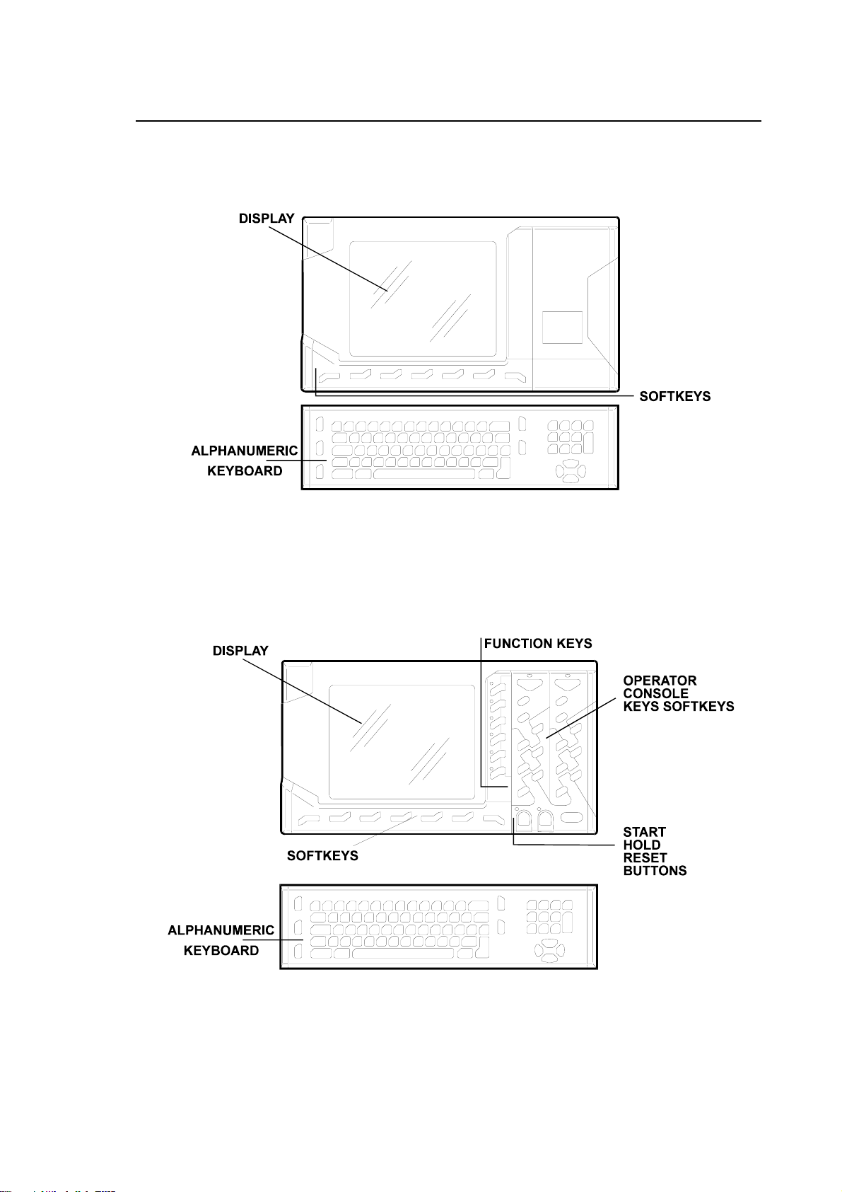
• BLink Operator Panel
Is the basic version to be used with an external Operator Console, available with a 10.4” TFT
colour screen.
BLink Operator Panel
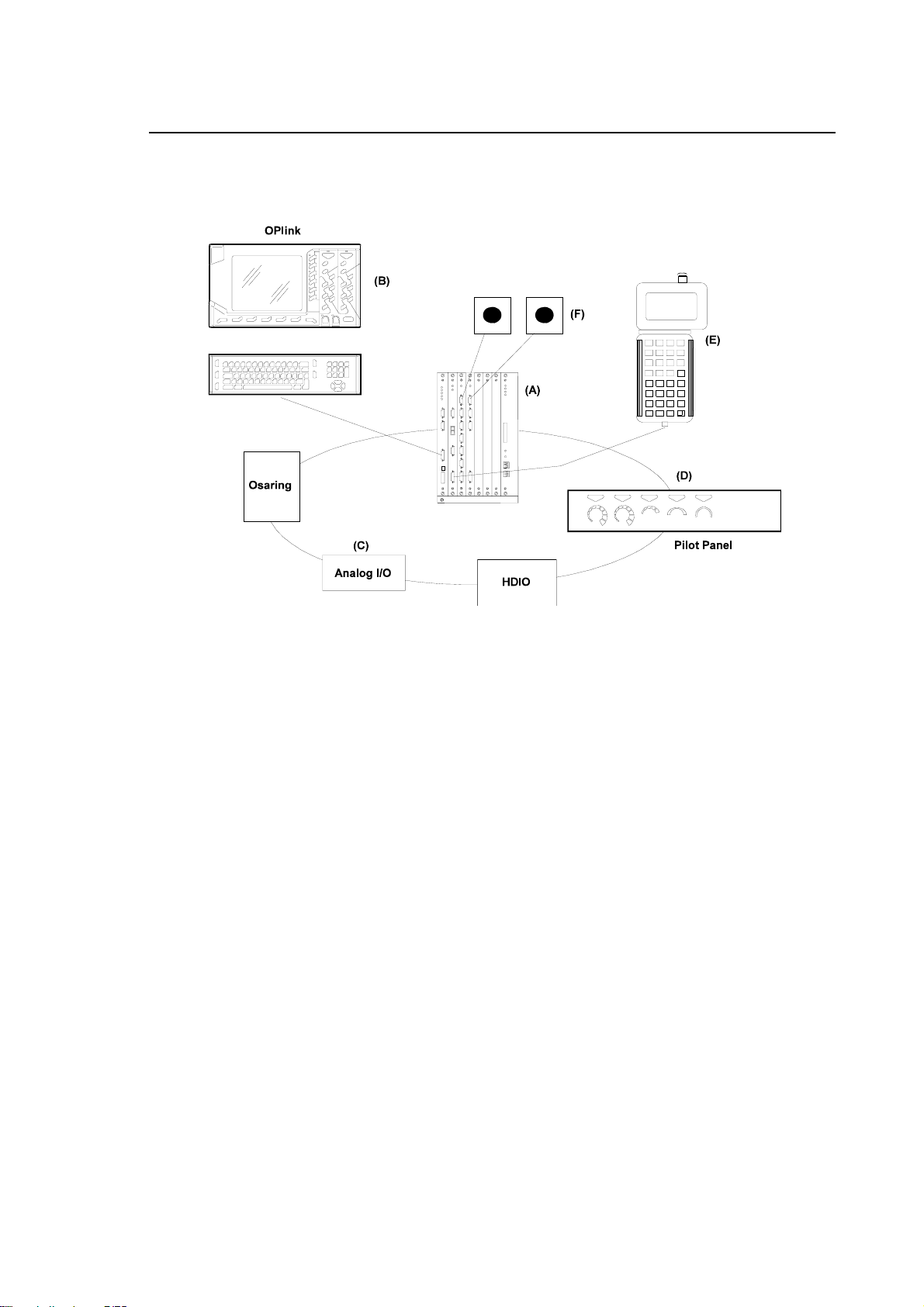
• OPLink Operator Panel
Is the version with a built-in Operator Console that provides CYCLE START; HOLD and RESET
buttons; keys for selecting the AUTO and MANUAL modes, for changing the spindle working and
rotating speed and 6 function keys with LED's which may be used by the manufacturer for machine
logic customization. It is available with a 10.4” TFT colour screen.
OPLink Operator Panel
10 Series CNC User Manual (14) 1-5
Page 22
Chapter 1
Features and Specifications
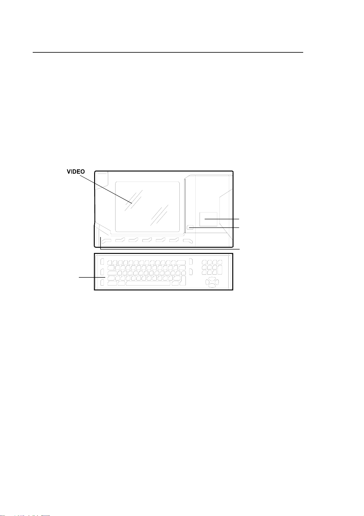
• WinLink Operator Panel
The WinLink front panel, shown in the diagram below, consists of a 10.4" o 12.1” TFT monitor,
alphanumeric keyboard, built-in mouse and built-in PC board (with its own HDU and 3.5" floppy
disk drive).
It has no RESET, START or STOP key.
It has a button ("yellow key") which is used for switching the monitor and keyboard from the NC
environment to the PC environment, and vice versa.
This front panel enables the monitor and keyboard to be shared by the NC and PC environments,
which remain completely separate.
On the built-in PC, you can use Windows applications that communicate with the NC using the Mini
DNC Ethernet option supplied with the dynamic library (DLL) developed for Windows.
ALPHANUMERIC
KEYBOARD
MOUSE
YELLOW BUTTON
WinLink type Operator Panel
1-6 10 Series CNC User Manual (14)
Page 23

Chapter 1
Features and Specifications
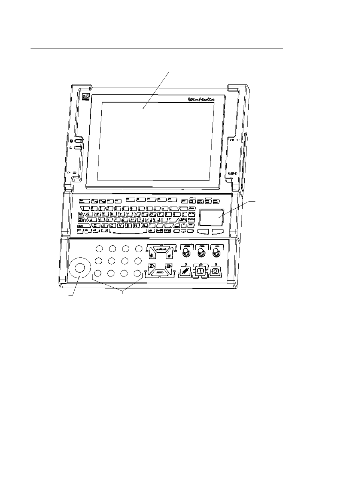
WINMEDIA
General
The WinMedia Operator Panel is a front-end module for use by the operators of the CNC to which
it is connected via the Ethernet line.
The panel can be supplemented with a keyboard connected directly to it and with an operator
console connected to a bus line extraneous to the module (communication bus lines such as
FastWire/CanOpen). The figure below shows a front view of the panel with the keyboard and the
console.
Main characteristics of the panel
Anchoring compatible with 19” pitch rack
15” TFT display screen
Fdu and Cd-Rom accessed from the front
Power supply: 90~265Vac 50~60Hz (100W max) *
connector conforming to IEC/EN60320-1/C14 (INLET type, i.e., with male contacts)
* Connection to safety GND by means of the power supply cord
Characteristics of Cpu board (ProX-3650)
850 MHz Celeron processor
CRT controller/ 640x480, 800x600, 1024x768 FLAT PANEL
256/512 Mbyte DDR SDRAM
128/256 Kbyte cache
4 Mbyte Flash BIOS (I/O Setup and VGA)
Mini DIN connectors for keyboard and Mouse
IDE (Hdu) controller
Fdu controller
3 RS232 serial ports
1 RS232/422/485 serial port
1 SPP, ECP, EPP parallel port
RJ-45 connector for 10/100 Base-Tx Ethernet
2 USB 2.0 ports on back
1 2.0 USB port on front panel
1 dedicated 2.0 USB port for Touch Screen
1 PISA slot for Riser Card
10 Series CNC User Manual (14) 1-7
Page 24
Chapter 1
Features and Specifications
LCD 15”
CDU FDU
USB
T. PAD
22 mm diameter
custom operator
16 mm diameter
12 custom operators
PC panel with keyboard and console – front view
1-8 10 Series CNC User Manual (14)
Page 25
Chapter 1
Features and Specifications
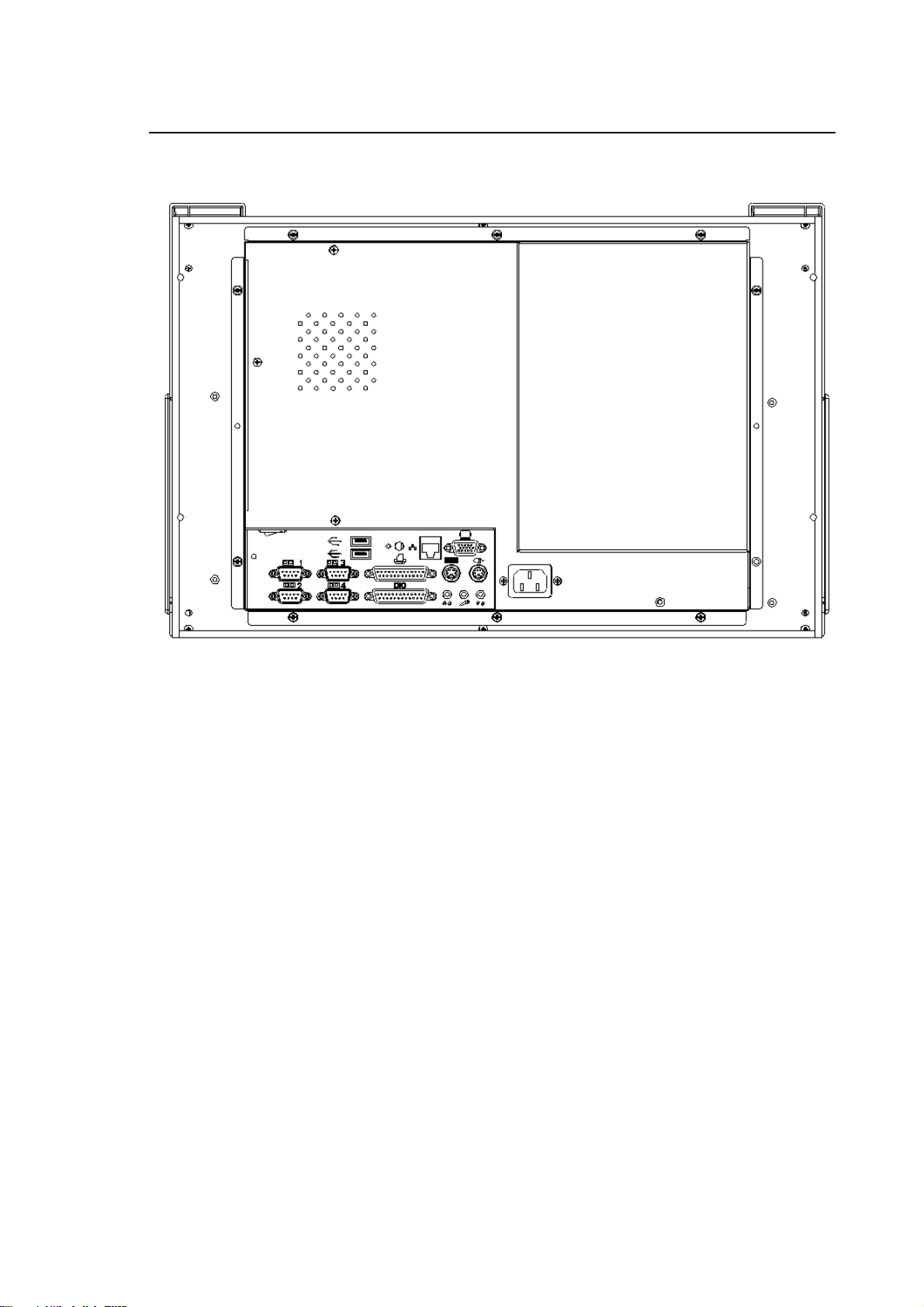
PC panel - rear view
10 Series CNC User Manual (14) 1-9
Page 26
Chapter 1
Features and Specifications
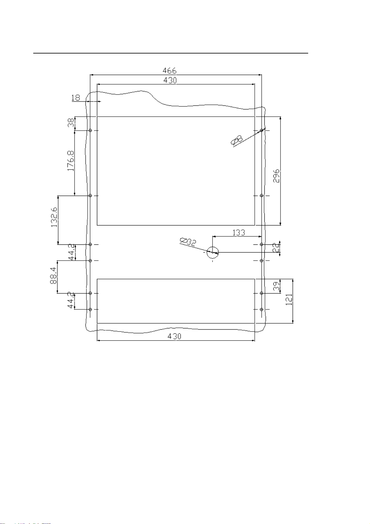
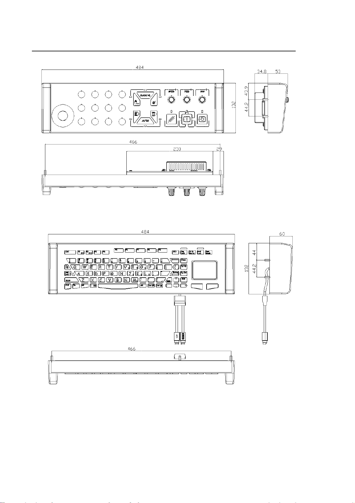
Panel - Keyboard - Console drilling template
1-10 10 Series CNC User Manual (14)
Page 27
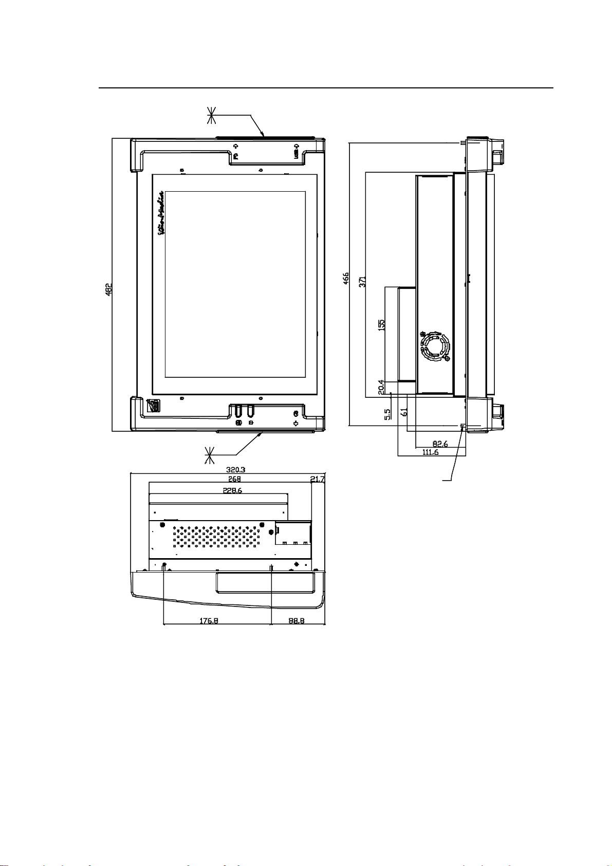
Chapter 1
f
Features and Specifications
4 M5 threaded pins
ATTENTION: when the FDU and CDROM options are present, it is
necessary to ensure an obstructionfree area, on the respective side, o
140 mm, to provide sufficient room to
introduce the floppy/compact disks
(zone marked with *).
On the right hand side, this area must
also be left unobstructed if one wants
to use the USB port for external units
(this port is always present).
Display panel drilling template
10 Series CNC User Manual (14) 1-11
Page 28
Chapter 1
Features and Specifications
Operator console drilling template
Keyboard drilling template
1-12 10 Series CNC User Manual (14)
Page 29
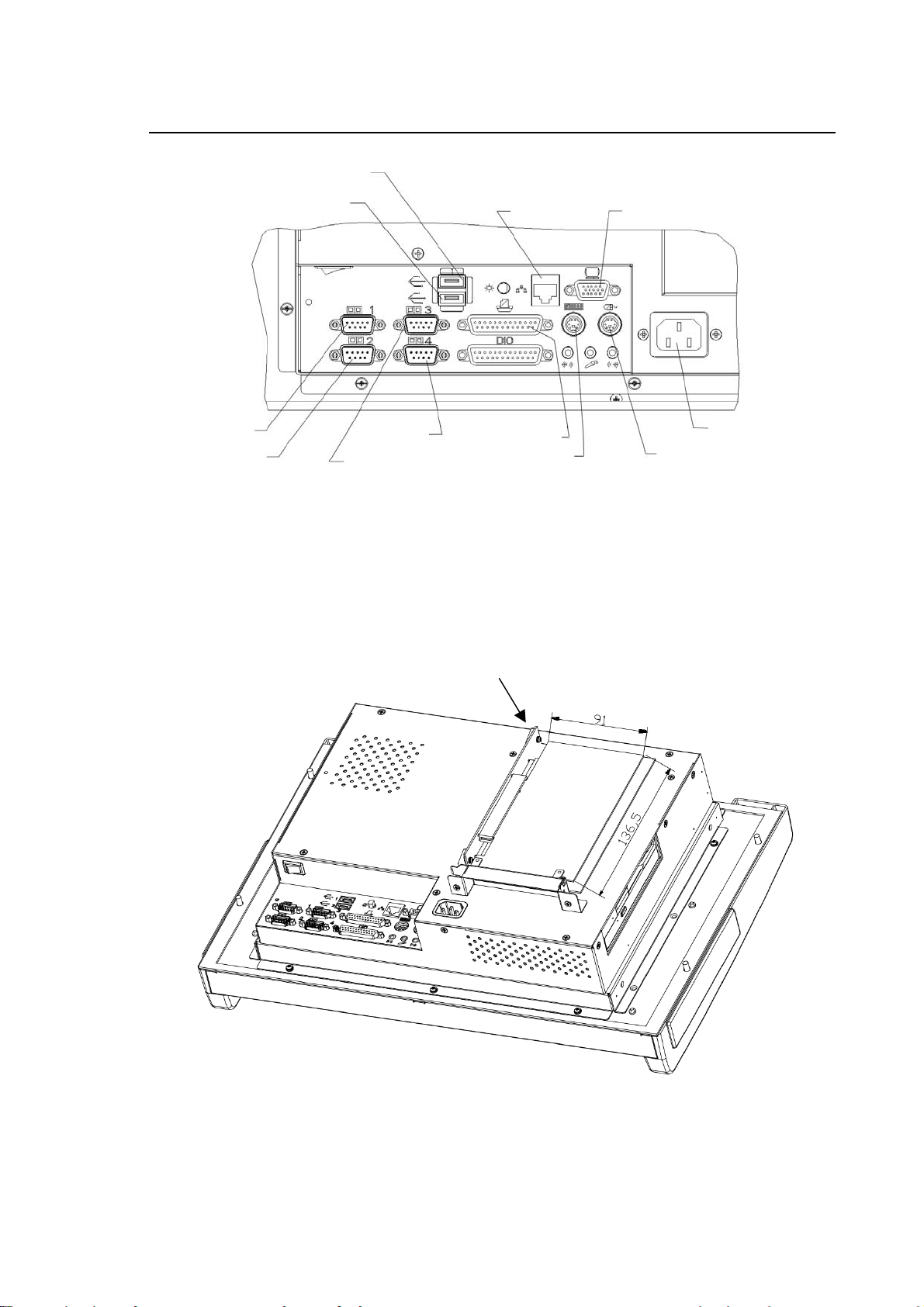
y
USB
A
Chapter 1
Features and Specifications
Com1
Com2
USB
Ethernet VG
Com4 Parallel port
Com3
Keyboard
PC Panel – Details of connectors
Power suppl
Mouse
Riser Card
PC Panel – Position of Riser Card
10 Series CNC User Manual (14) 1-13
Page 30

Chapter 1
Features and Specifications
Mass storage
Mass storage by means of an HDU with a capacity of 20 and more Gbytes, mounted inside the
module.
FDU peripheral
The module uses an integrated FDU peripheral, fitted to the left part of the panel (option).
CD-ROM peripheral
The module has an integrated CD-ROM peripheral, fitted to the right part of the panel (option).
Keyboard connection
The keyboard is connected by means of a special Mini Din connector on the back of the module.
Mouse connection
The mouse is connected by means of a special Mini Din connector on the back of the module.
Ethernet connection
The Ethernet connection of the module to an external unit or a network is by means of a special
connector on the back. To connect the module to a PC or other similar units you need a crossover
cable, to connect it to a HUB you need a straight cable (see the Connectors/Cables section).
Riser Card
A Riser Card fitted to the special PISA connector makes available a PCI/ISA expansion connector
on the back.
External connections
Back
Com1, Com3, Com4 RS232
Com2 RS232/RS422/RS485 (configurable)
Parallel port
LAN (Ethernet)
Keyboard (6-pin Mini DIN)
Mouse (6-pin Mini DIN)
Display screen (15-pin) Not used
USB, USB (two ports)
AC Pwr in Module power supply
Front
USB (one port)
1-14 10 Series CNC User Manual (14)
Page 31
Chapter 1
Features and Specifications
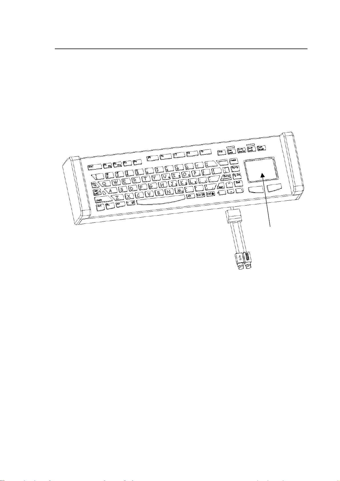
Keyboard
The keyboard has a standard Windows PC configuration with 83 short-stroke keys of silicone
rubber and a built-in mouse pad with right and left mouse keys. The two (independent) sections are
connected to the WinMedia module by means of two cables ending with Mini DIN connectors. PS2
standard communication protocol.
WinMedia keyboard
Touch Pad
KeyboardMouse
10 Series CNC User Manual (14) 1-15
Page 32

Chapter 1
Features and Specifications
Operator Console
Specification
The Operator Console is recognised by the NC as an I/O module managed through the FastWire
or CanOpen line and it includes:
* Operators (trimmers): SPEED – FEED – JOG
* Selector buttons: CYCLE START – HOLD – RESET
JOG INC – MANUAL – HOME
MDI – AUTO – BLK/BLK
* Active functions LEDs
* 12 locations for 16 mm diameter custom operators
* 1 location for a 22 mm diameter custom operator
22 diameter
custom operator
(yellow badge for
emergency button)
12 16mm diameter
custom operators
Front view of console
1-16 10 Series CNC User Manual (14)
Page 33

Chapter 1
CONN. ALIM
Features and Specifications
24 V OUT
CONN. ALIM.
SW1
POWER CONN.
SW2
OUT 24V
FASTWIRE LINE CONN.
CONN. LINEA FAST WIRE
CanOpen LINE
CONNECTOR
& NETWORK
SIDE POWER
SUPPLY
SW1
SW2
MODULE POWER
SUPPLY CONN.
“BUS” LED “RUN” LED
LED "BUS"
CONN. LINEA CanOpen
E ALIM. LATO RETE
“BUS” LED “RUN” LED
LED "BUS"
LED "RUN"
“FAULT” LED
LED "FAULT"
MODULE POWER
SUPPLY CONN.
LED "RUN"
“FAULT” LED
LED "FAULT"
.
MODULO
12 16mm DIAMETER CUSTOM OPERATORS
12 OPERATORI CUSTOM DIAMETRO 16 mm
CUSTOM
CONN.I/O 24V
24V I/O CONN.
CUSTOM
Console - Rear view of FastWire version
CONN. ALIM.
MODULO
12 16mm DIAMETER CUSTOM OPERATORS
12 OPERATORI CUSTOM DIAMETRO 16 mm
CUSTOM
CONN. I/O 24V
24V I/O CONN.
CUSTOM
22mm DIAMETER
OPERATORE CUSTOM
CUSTOM OPERATOR
DIAMETRO 22 mm
22mm DIAMETER
OPERATORE CUSTOM
DIAMETRO 22 mm
CUSTOM OPERATOR
Console - Rear view of CanOpen version
10 Series CNC User Manual (14) 1-17
Page 34

Chapter 1
t
Features and Specifications
SOFTWARE STRUCTURE
The figure that follows illustrates the software structure. Note that the Event-Driven Real-Time
Multi-Task IntePprocess Communications software (IPC) overlaps the basic operating system that
manages communications with the operator panel. IPC also supervises and synchronises
communications between the five software partitions.
Communications with
Operator Panel
Operating System
IPC (Interprocess Communication)
Real Time
DOS
Interface
Table
Editor
PLUS
Editor
Human
Interface
Graphic
Editor
Utility
Digitizing
Option
AMP
Machine
Logic
Interface
DOS
Graphic
Interface
Numerically
Controlled
Proces
Serial
Mini
DNC
Etherne
SOFTPIT.DRW
1-18 10 Series CNC User Manual (14)
Page 35

Chapter 1
Features and Specifications
The functions of the five system partitions are as follows:
NC Process: Includes the Part Program interpreter. It interpolates the controlled
axes and manages processes in machining centers.
Machine Logic Interface: Executes the OEM-developed interfaces between the NC and the MT.
Utilities: Includes a series of packages aimed at the end user, the MTB or the
technical assistance engineer. Some are described later in the
manual, others are optional (purchased separately).
Human Interface: The NC-operator interface manages visualisation, program editing
procedures, softkey operation, help pages, etc.
Real-time DOS Interface: Is the 10 Series "aperture" to OEM for the building of personalised
applications.
These applications can use all the 10 Series resources (axes, logic,
human interface, etc.), as well as those of the Operating System
(realtime, multitask, etc.).
10 Series CNC User Manual (14) 1-19
Page 36

Chapter 1
Features and Specifications
Utilities
A utility is a standard or optional program addressed to various users levels (end user, MTB,
technical assistance engineer, etc.). The 10 Series Utilities partition includes:
Table Editor Permits to key in, display and edit the parameters that define the
following features:
− origins
− tools
− tool offsets
− tool tables
− tool magazines
− tool data base
The Table Editor includes the Editor Configurator Table, which permits to
personalise the contents and the layout of the tables displayed by the
system. For details, refer to Chapters 7 and 8.
PLUS Editor PLUS (Parallel Logic Universal System) is a complete universal
programming language used for writing the machine logic that manages
the interface between the 10 Series and the machine tool. PLUS collects
information about the current process, the axes functions and the system
variables and uses this data to make decisions about the machining
process and other actions. For more information see the relative
documentation, particularly the 10 Series CNC PLUS Library Manual.
Graphic Editor This option permits to write programs using graphic menus. The Graphic
Editor can be broken down into two utilities:
The Geometric Editor generates a profile from the definition of its
elementary geometric constituents. The desired profile is obtained by
linking these constituents.
The Cycle Editor permits to program canned machining or measuring
cycles. The programmer is presented with a choice of graphic options
and of parameters that define them.
For more information about this option, refer to the 10 Series CNC
Graphic Editor Manual.
1-20 10 Series CNC User Manual (14)
Page 37

Chapter 1
Features and Specifications
Digitizing This option permits to program complex profiles (such as those including
spline curves) using points captured with different methods. Digitizing
methods include manual moves, probing cycles and keyboard entries.
Points can also be uploaded from an external computer.
For more information about this option, refer to the 10 Series CNC
DIGICAD User Manual.
AMP The Adjustable Machine Parameters (AMP) permits the user to tailor the
10 Series control to the system applications.
The following is a list of configurable system parameters:
− number of axes and axes parameters (gain, velocity, electrical and
mechanical pitch, etc.)
− operator interface or visualisation technique
− system variables
− hardware system configuration
− number of processes
− user-specific DOS packages
− auxiliary functions
− travel limits
− etc.
For more information about this option, refer to the 10 Series AMP
Software Characterization Manual.
DOS Graphic Interface This option permits the user to customise the machine by writing
application programs in C language and using the DOS Graphic Interface
libraries. For more information about this option, refer to the 10 Series
CNC DOS Graphic Interface Manual.
MINI DNC This option permits network connection of 10 Series systems and a PC
for exchanging files (part programs, etc.) and for communication between
processes ("task to task").
There are two types of connections:
− over a RS-232 serial line
− PC connected over an Ethernet link to various systems.
For more information about this option, refer to the MINI DNC
Serial/Ethernet Manual.
10 Series CNC User Manual (14) 1-21
Page 38

Chapter 1
Features and Specifications
In addition to the options listed and displayed in the figure, 10 Series systems offer other options
now listed below:
Tool Management Manages the flow of tool information between the Tool Magazine and the
shop floor, and the operations for moving the tools in the machine.
For more information about this option, refer to the 10 Series CNC Tool
Magazine Option.
Electronic Cam This option permits to define a master axis and a slave using the
positioning values stored in predifined tables. The master/slave pair
sampling tick can be much smaller than that available with ordinary
programming and calculation methods.
Oscilloscope This standard feature permits to visualise in a continuous graphic the
feedrate or the following error of the axes, and to store the relevant data
in a file.
System History This standard feature permits to store in a file all the diagnostic
messages sent by the system when erroneous operations are performed
or a mulfunctioning occurs. Messages are complete with date and time.
This file is of considerable importance for troubleshooting and diagnostic
purposes.
END OF CHAPTER
1-22 10 Series CNC User Manual (14)
Page 39

Chapter 2
SYSTEM START UP
SYSTEM POWER UP
The system is powered up when power is supplied to the central unit and the front panel. To do this
you must typically operate the machine main power switch.
Since most of the system software is stored in the hard disk, at power up the system automatically
loads the NC management software in the system memory.
DIAGNOSTIC SCREENS
At power up the system also launches a diagnostics of the system hardware and software
modules. The diagnostic sequence is as follows:
• hardware (CPU, ROM, RAM, keyboard and hard disk)
• additional boards and devices
• NC software
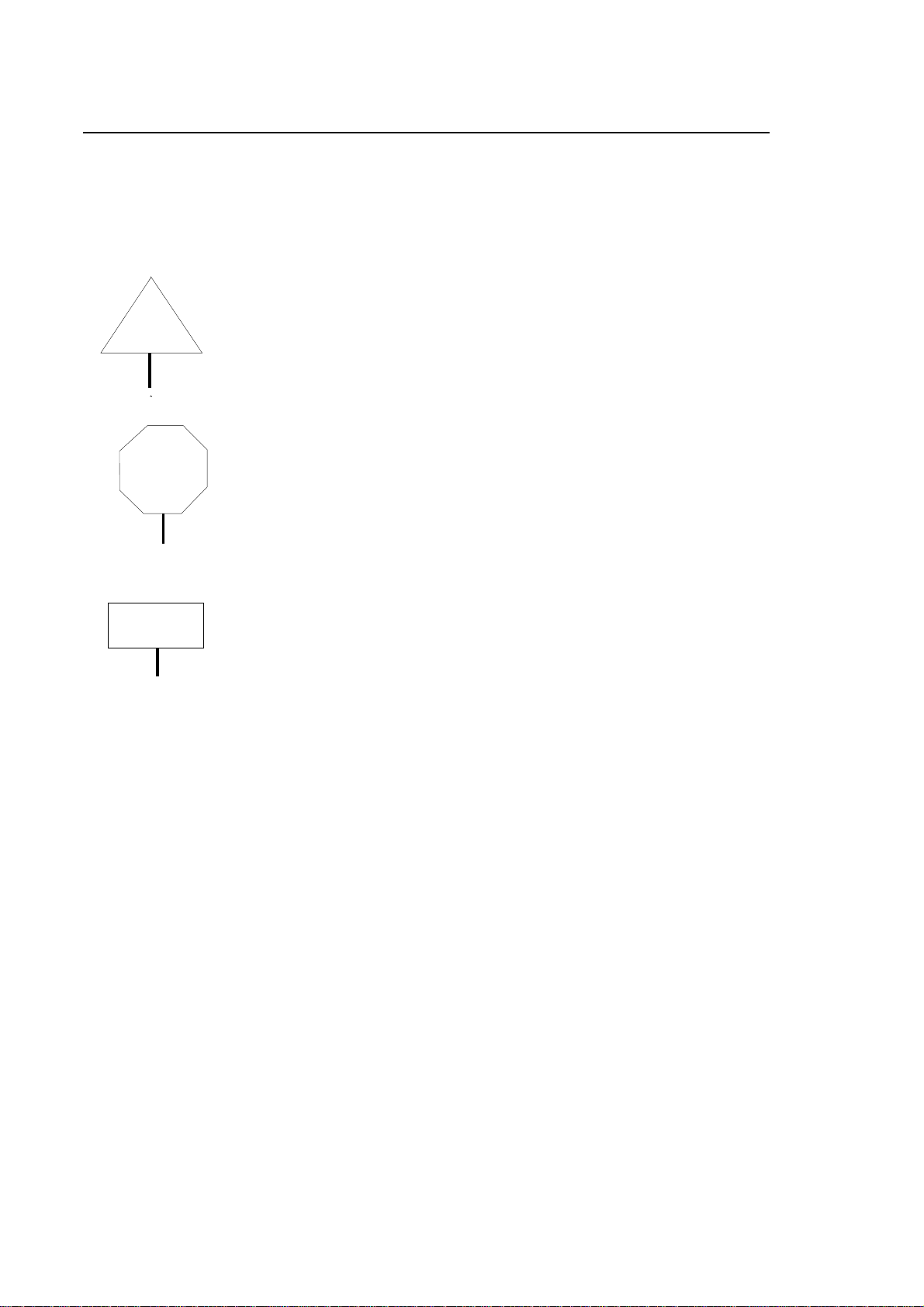
To each diagnostic module corresponds a screen similar to the one shown in the figure below.
On the intelligent front panel (in systems equipped with this model of front
CAUTION
panel), the messages displayed on the screens may vary.
For a list of all error messages for this type of operator panel, see the
relevant section of Appendix A.
10 Series CNC User Manual (15) 2-1
Page 40

Chapter 2
System Start up
A
MAIN CPU HARDWARE DIAGNOSTIC
CPU ROM
B5.1.2
RAM KEYB DISK
B
10% 20% 30% 40% 50% 60% 70% 80% 90% 100%
RAM : BD002 CMOS Memory Battery backup PASSED
C CPU : BD000 Math Processor PASSED
DISK : BD004 Fixed Disk: 1 present PASSED
DISK : BD004 Floppy Disk : 1 present PASSED
Data Logger Display
A "LED" Area
B Percentage of Loaded Software
C Message Area
The diagnostic screen can be partitioned into three main areas:
A "LED" Area: this area displays 5 or 6 boxes, each one of which represents a diagnostic LED.
The name of the label indicates the device tested by the diagnostic routine. The boxes are
displayed in green when the modules pass the test. They are displayed in red when a failure
occurs. In this case, a fixed label indicates a locking error, whereas a blinking label indicates a
non-locking error. The error will be further described in the data logger display area.
B Percentage of Loaded Software: as the software is loaded in the system memory during
initialisation, the color bar displayed in this area shows the loaded percentage.
C Data Logger Display: this area displays the test results. The layout of a typical message line is
as follows:
2-2 10 Series CNC User Manual (15)
Page 41

Chapter 2
System Start up
KEYBO: BD003 KEYBOARD PASSED
test results
test description
message code
tested device
The meaning of these columns is as follows:
Tested Device is the acronym of the device, typically the label displayed on the diagnostic
"LED" area.
Message Code is the acronym of the diagnostic message. It is made up of two letters and
three digits. In the standard front panel this acronym corresponds to the
message code listed in Appendix A. Note that this appendix also provides
the description of the failure and the remedial action.
Test Description provides a short description of the test (if passed) or an error message when
an error has been detected.
Test Results this column may display one of these messages:
PASSED the device has passed the test.
WARNING the device has not passed the test but the error is not a
locking one. When this occurs, the LED is displayed in red
with a blinking label. The WARNING message is written in
white letters on a red background.
FAILED the device has not passed the test and the relevant LED is
red.
REPORT an optional device (mathematical coprocessor, software
package, etc.) is present. This message also appears to
indicate that the system is going through initialisation or is
configuring the software.
In general only one FAILED message is displayed when a locking error occurs. On the contrary,
when more than one WARNING must be displayed, the following string appears:
Press enter to continue
When this message appears, the test stops. To display all the messages that cannot be
accomodated in the message area it is necessary to press the [Arrow Up/Down] arrow keys. To
resume the test press [Enter].
10 Series CNC User Manual (15) 2-3
Page 42
Chapter 2
System Start up
Modules
The LED labels and the messages displayed in the Data Logger Display vary with the type of
tested module.
As a result various possible conditions may be displayed sequentially while the relevant module is
tested:
MAIN CPU HARDWARE DIAGNOSTIC
Basic hardware
(system CPU)
Additional hardware
(any boards installed)
NC software
CPU ROM
B02.03A
CNC SOFTWARE DIAGNOSTICS
PLUS AXIS
CNC SOFTWARE DIAGNOSTICS
OS
V03.00
PLUS
V03.00
RAM KEYB DISK
SERVO
V03.00
PROCESS
V03.00
HUMAN
V03.00
On the new 10/110 controls of the 10 Series, the initial diagnostic phase in which the basic
hardware components are tested is displayed in a different format typical of the diagnostic
messages displayed on standard personal computers.
On the other two models, the diagnostic screens are as described.
2-4 10 Series CNC User Manual (15)
Page 43

Chapter 2
System Start up
EMERGENCY SYSTEM SWITCH-ON
It is possible to perform a "minimum" bootstrap on 10 Series systems in which some operations
only executed in this environment can be perfromed, while not activating all the system features.
IMPORTANT
The minimum bootstrap is activated by holding down the [F1] button when
switching the system on.
The system will be brought up with the EMERGENCY DIAGNOSTIC
screen:
IMPORTANT
If the front panel is WinLink type, first press the "yellow button" when
switching on and then, after switching video and keyboard to NC
environment, press [F1].
The system will be brought up with the EMERGENCY DIAGNOSTIC
screen:
In emergency, the following softkeys are available:
• AMP
This softkey grants access to the AMP utility for system characterisation. The functions of this
utility are described in the Characterisation Manual.
• PLUS
Grants access to the PLUS environment for development of the machine logic programs. For
further details, read the PLUS manuals.
• VARIABLE RESET
With this utility, the dual port memory areas present in the system can be initialised, saved in a
file and restored from a file. This topic is discussed in the Characterisation Manual.
• SYSTEM HISTORY
This softkey grants access to the utility for display/printing/deleting of the history log of errors
and system messages displayed during operation of the machine. This file has a fixed size,
which means that beyond a certain number of messages, new incoming reports will involve the
oldest reports being pushed out.
• HELP
Displays the on-line help window.
• DOS SHELL
This softkey grants access to the DOS SHELL utility.
This utility permits execution of commands for control of the files in the drives acknowledged by
the system (local or remote). Further information on this utility may be found in this manual.
• SECURITY
Manages the system security levels at the different user levels. Further information on this utility
may be found in this manual.
10 Series CNC User Manual (15) 2-5
Page 44

Chapter 2
System Start up
• TABLE EDITOR
This utility grants management of the system tables; further information on this utility may be
found in the 10 Series CNC user manual.
• PERIPHERALS
Permits selection of the output port for the system printer or for use in the DOS environment.
• LANGUAGES
This is a utility permitting personalization of the national language of the mesages displayed in
the HELP, SOFTKEY, etc. Further information on this utility may be found in the
Characterisation Manual.
• SYSTEM SHUT DOWN
This is used to perform a bootstrap, as recommended after making changes to the software
characterisation or the machine logic, and it is also used to shut down the system.
• COMPILER
Allows compiling and linking of source files written in C or ASSEMBLER.
• UTILITY
Permits execution of what is specified in file E:UTY\AUTOEMG.BAT or in file
A:\AUTOEMG.BAT, present on a diskette.
This is a utility permitting execution of programs for Hard Disk compacting, system scanning in
search for "viruses", or other programs selected by the OEM.
File E:\UTY\AUTOEMG.BAT (or a copy on diskette) must be modified for use of the utilities the
OEM wishes to execute, the file itself presents an example of the typical structure to follow.
2-6 10 Series CNC User Manual (15)
Page 45

Chapter 2
System Start up
DIAGNOSTIC MESSAGES
As mentioned previously, the messages on the diagnostic screens vary according to the type of
module being tested.
The messages about optional devices display the REPORT label in the result area, whereas actual
test results may be indicated by PASSED, FAILED or WARNING..
IMPORTANT
In the WinLink front panel it must be recalled that on bootstrap of the full
system (NC and WinLink), the default video is that of the integrated PC and
the diagnostic will also be the PC diagnostic; the NC diagnostic will be
visible only following a switch of operating environment on pressing the
"yellow button".
An example of the sequence of PASSED or REPORT messages that may be displayed during the
test carried out on the modules of a 10 Series system (except for the 10/110 model).
The BD acronym given in the table does not identify a single message but, rather, a tested group,
i.e. CPU, RAM, etc.
10 Series CNC User Manual (15) 2-7
Page 46

Chapter 2
System Start up
PASSED Tests
Device Acronym Description Result
CPU BD000 Processor PASSED
The CPU has passed the autodiagnostics.
CPU BD000 Interrupt Controllers PASSED
The interrupt controllers have passed the test.
CPU BD000 DMA Controllers PASSED
The direct memory access controllers have passed the test.
CPU BD000 Pointing Device PASSED
The mouse hardware has passed the test.
CPU BD000 Clock/Calendar PASSED
The real time clock registers work properly.
CPU BD000 CPU Protected Mode PASSED
The protected CPU mode has passed the test.
ROM BD001 PRODUCT KEY Checksum PASSED
The checksum of the product electronic key is correct.
RAM BD002 CMOS Memory Battery Back Up PASSED
The back up battery of the CMOS has passed the test.
RAM BD002 Parity Circuitry PASSED
The circuitry that generates the parity bit for RAM control has
passed the test.
RAM BD002 CMOS RAM PASSED
The CMOS RAM has passed the test.
KEYBO BD003 Keyboard PASSED
The keyboard circuitry has passed the test.
DISK BD004 Fixed Disk: 1 present PASSED
The hard disk unit is present and works properly.
DISK BD004 Floppy Disk: 1 present PASSED
The floppy disk unit is present and works properly.
2-8 10 Series CNC User Manual (15)
Page 47

Chapter 2
System Start up
REPORTS about devices and actions in progress
Device Acronym Description Result
CPU BD000 Math Processor REPORT
The mathematic coprocessor is present.
DISK BD039 Fixed Disk Present REPORT
The hard disk is present.
DOS BD102 Primary Bootstrap REPORT
MS DOS is being initialised.
DOS BD104 Remove the diskette and strike any key REPORT
DOS BD106 Insert release floppy n. 1 and reboot the control REPORT
This message appears while the system is loading the SW
release from a diskette.
OS OD001 Operating System Loading / Loaded REPORT
The NC operating system is being loaded or has been
loaded in the system memory.
OS OD002 File Server Loading REPORT
The NC operating system is being loaded in the system
memory.
OS OD003 Application Loading REPORT
The application program is being loaded in memory.
OS OD100 RS232 Software Loading REPORT
The serial communications software is being loaded in
memory.
OS OD101 SK-NETBIOS Software Loading REPORT
The protocol of the SK-Netbios sofware for the MINI DNC
Ethernet option is being loaded in memory.
OS OD102 DEC-NETBIOS Software Loading REPORT
The protocol of the DEC-Netbios sofware for the MINI DNC
Ethernet option is being loaded in memory.
PLUS (*) HD061 Loaded Boot strap Program REPORT
The PLUS initialisation program has been loaded in
memory.
PLUS (*) HD062 Check RAM REPORT
The board has passed the RAM test.
10 Series CNC User Manual (15) 2-9
Page 48

Chapter 2
System Start up
Device Acronym Description Result
PLUS (*) HD063 Loaded Diagnostics REPORT
The board diagnostic program has been loaded in memory.
PLUS SD000 PLUS Environment Creation REPORT
The creation of the PLUS environment has been completed.
SERVO SD000 Servo Environment Creation REPORT
The creation of the SERVO environment has been
completed.
PROCESS SD000 Process 1 Environment Creation REPORT
The creation of the PROCESS 1 environment has been
completed.
PROCESS SD000 Process 2 Environment Creation REPORT
The creation of the PROCESS 2 environment has been
completed.
PROCESS SD000 Process 3 Environment Creation REPORT
The creation of the PROCESS 3 environment has been
completed.
PROCESS SD000 Process 4 Environment Creation REPORT
The creation of the PROCESS 4 environment has been
completed.
PLUS SD000
HUMAN SD000 H-I Environment Creation REPORT
OEM SD000 OEM Environment Creation REPORT
(*) Acronyms HD061-063 refer to a whole series of boards and devices. For example, in HD061
the message may refer to AXIS 1, AXIS 2, etc. rather than to PLUS.
Creating I/O Environment REPORT
The creation of the I/O environment has started.
The creation of the User Interface environment has been
completed.
The creation of the OEM environment has been completed.
Error messages
Locking (FAILED) and non-locking (WARNING) error messages and remedial actions are
described in Appendix A.
END OF CHAPTER
2-10 10 Series CNC User Manual (15)
Page 49

Chapter 3
USER INTERFACE
The user interface is the means by which the operator communicates with the system. The screen
provides the operator with visual system information, while the operator uses the keyboard and the
pushbuttons available on the front panel for entering parameters, instructions and commands.
This chapter describes 10 Series keyboard, video pages and softkeys.
KEYBOARD
The 10 Series keyboard includes:
• 3 function keys, [F1] - [F3] on the left-hand side
• 2 function keys, [F11] and [F12], on the right-hand side
• an alphanumeric section
10 Series CNC User Manual (15) 3-1
Page 50

Chapter 3
User Interface
Function keys
[F1] - [F3] These function keys are not used; they are reserved for use by OEM operators.
[F11] - [F12] These function keys are not used; they are reserved for use by OEM operators
(on the WinLink front panel).
Alphanumeric Section
This section of the keyboard consists of 89 keys which may be identified in three areas of the
figure: the function keys, the typewriter section and the numeric keypad, which are used for
entering data, moving the cursor and scrolling through video screens. The following keys perform a
particular function in the alphanumeric section:
The [Arrow Up/Down] [Arrow Left/Right] keys move the cursor in the
direction indicated by the arrow. They may be used in input boxes,
utilities, editing operations and for selecting axes in manual movements.
The [Return] key is used for moving the cursor from one field to
another in input boxes, tables, etc.
The [Enter] key is used for confirming input boxes and, more generally,
data entered on the keyboard.
The [Pg Up] and [Pg Dn] keys are used for scrolling through help
pages on the screen, program listings in the line editor and table data in
the Table Editor. In general, they are used for scrolling through a list of
items when the list is longer than the video screen on which it is
displayed.
The [Home] key is used for moving the cursor to the start of the
programs directory or, when pressed together with [Ctrl], to the start of
the program listing.
The [End] key is used for moving the cursor to the end of the programs
directory or, when pressed together with [Ctrl], to the end of the
program listing.
3-2 10 Series CNC User Manual (15)
Page 51

Chapter 3
User Interface
The [Esc] key clears the input box without saving any changes made
The [Ins] key is used for switching from overwrite to insert typing mode
or vice versa
The [Back Space] key deletes the first character to the left of the
cursor.
The [Delete] key deletes the character at the cursor position.
The [Clear Msg] key removes the following types of messages from the
screen::
- PLUS messages
- process (*) and emergency (*) messages
(*)for these environments, the function of the Clear Msg key may be
configured (see the documentation of the "LANGUAGES" package).
The [Clear Line] key deletes the contents of the manual data entry line
on which the cursor is positioned.
The [Caps Lock] key changes the typing mode from capital to small
letters and vice versa.
The [Shift] key, when pressed together with a key, is used for
performing the upper-case functions indicated at the top of the
associated key.
The [Alt], [Ctrl], [Pause] [Break], [Print] keys are not used; they are reserved for use by OEM
operators.
10 Series CNC User Manual (15) 3-3
Page 52

Chapter 3
User Interface
OPERATOR PANEL FUNCTION KEYS
Function keys [F4] to [F10] situated at the bottom of the operator panel are reserved for softkeys
and fixed keys.
The five softkeys enable the user to send commands to the 10 Series CNC system. Their function
is determined by the software in each individual case through a series of menus. The menus have
a hierarchical structure and are displayed on the bottom three lines of the screen. The active line of
a menu establishes the current functions of the softkeys.
A detailed description of the softkeys is provided later in this chapter.
Key [F5] SOFTKEY 1
Key [F6] SOFTKEY 2
Key [F7] SOFTKEY 3
Key [F8] SOFTKEY 4
Key [F9] SOFTKEY 5
Fixed Keys
The fixed keys are located on either side of the softkeys and have the following functions:
Key [F4]
The left fixed key always takes you back to the main menu and
displays the main screen, thus facilitating access to the machining
environment.
Key [F10]
The right fixed key is used for changing the active line of the
softkeys by moving the blue bar vertically through the three lines of
softkeys.
3-4 10 Series CNC User Manual (15)
Page 53

Chapter 3
User Interface
Special keys
yellow button This button on the WinLink front panel is used to switch video and keyboard
from the integrated PC to the NC and vice versa, without affecting any ongoing
operations on the two systems.
keys P1÷ P6 These 6 function keys present on the WinLink and OPLink front panel are at the
operator's disposal for customising the functions.
IMPORTANT
• On the WinLink front panel, these keys and their LED's may ONLY be
controlled from the PC side.
• On the OPLink front panel, these keys and their LED's may be controlled
by the machine logic (OEM SOFTKEY tasks)
10 Series CNC User Manual (15) 3-5
Page 54

Chapter 3
User Interface
CONTROL BUTTONS
The three control buttons perform the following functions:
The RESET button aborts the part program being executed and any
active function.
The CYCLE START button starts executing the part program and
enables the axis homing cycle and the execution of manual
movements.
The CYCLE STOP button stops various functions depending on
whether the system is in Auto or Manual mode. In particular:
Auto stops executing the part program with controlled
deceleration of motion. To exit from the cycle stop
condition, press CYCLE STOP again; the process enters
HOLD RUN status. To resume execution, press CYCLE
START.
Manual stops the automatic axis homing cycle, incremental JOG
motion and automatic return from JOG. To exit from the
cycle stop condition, press CYCLE STOP again. To
resume execution, press CYCLE START.
More detailed information on each key will be provided in this manual as it is mentioned in the
descriptions of the single operations.
3-6 10 Series CNC User Manual (15)
Page 55

Chapter 3
User Interface
VIDEO
10 Series systems use the video for visualising information about system operation and functions,
requesting parameters or instructions, etc.
The video is a 12" color screen with 640 x 480 resolution. It can display up to 25 80-character lines.
Screen lines are partitioned as follows:
• the first line always displays system status information
• the last three lines are always occupied by the softkey menu
• the remaning 21 lines are used for information display. The layout may vary enormously
according to the context in which visualisation occurs. In some cases one of the lines in this
area displays error messages.
Displayed information may occupy the whole data area of the screen or just a quadrant of it. Each
quadrant is made up of 10 39-character lines. A quadrant may be enlarged to occupy the whole
screen by means of the ENLARGE softkey, as shown in the figure below. The enlarging procedure
will be described later in this chapter.
The table below lists the video pages managed by the system. The first three and the last six are
standard; the others can be configured in the AMP environment from standard quadrants, special
screens created by the logic, or customised screens written through the ASSET utility.
Supplementary screens 1 through 5 are configurable, whereas Logic quadrants 1 through 4 can be
customised and subsequently managed as configurable screens
10 Series CNC User Manual (15) 3-7
Page 56

Chapter 3
User Interface
Video
Description
type
①
Main process screen
①
Main logic screen
①
Axes coordinates in large scale
①
Logic screen 1
①
Logic screen 2
①
Logic screen 3
①
Logic screen 4
①
Supplementary screen 1
①
Supplementary screen 2
①
Supplementary screen 3
①
Supplementary screen 4
①
Supplementary screen 5
¼ Logic quadrant 1
¼ Logic quadrant 2
¼ Logic quadrant 3
¼ Logic quadrant 4
¼ System status quadrant
¼ Axes coordinates quadrant
¼ Part program display quadrant
¼ Process status quadrant
¼ Programmed code status quadrant
¼ Axes offset parameters quadrant
① Full screen page
¼ Quadrant page
An example of AMP configurable screen could be a Supplementary screen made up of 4
quadrants: the upper left one displays the system status, the upper right one displays the process
status, the lower left one displays the part program and the lower right one the axes coordinates.
Further information about supplementary screens will be provided later in this chapter.
The screens displayed by the system may accomodate overlapping windows that provide system
messages or additional information on request. These windows will be discussed later in this
chapter.
The sections that follow describe the main system screens. Other screens, such as the Editor
screens or the various Tables, will be discussed in the chapters dedicated to the relevant
environments.
3-8 10 Series CNC User Manual (15)
Page 57

Chapter 3
User Interface
Main screen
This screen is normally displayed during cycle execution. It provides the end user with information
about the machining environment. This information is partitioned into five areas, as shown in the
figure below:
A PROCESS CONTROLLED: 1 CAPS ON SCREEN 1 OF 4 TIME: 9:35:00
PROC: 1 IDLE AUTO OPT STOP RETRACE
AXIS WORK [mm] PROGRAMMED ORIGIN
L
LMXY
B
Z
A
B
S: 100.000 F: 1000.000
C
112.5% 75.000 100.0% 900.000 100.0% xxxxxx
G: 00 80 99 40 27 90 71 17 94
M: xx xx xx xx
RAP: 0.0000 ACT : Txx.xx
97
d: 0.000000
- 149.00000
32.25603
0.00000
0.00000
0.00000
NXT: Txx.xx
JOG: 0.00000 Z: 0.000000
-149.23600
33.39406
0.00000
0.00000
0.00000
1
2
TI
0
0
0
PROGRAMS: MAINPROG SUB1 SUB2
N26 S2000 F200 T3.03
N27 (UTO,1,X30,Y22)
D
E AUTO MANUAL PART PROGRAM VARIABLES OEM SOFTKEY
MACHINE SETUP TABLES DIAGNOSTICS PERIPHERALS UTILITY
N28 (ROT,20)
N29 G81 R-90 Z-110 M3
N30 X25 Y25
N31 X40 Y10
N32 X25
POS DISPLAY NEXT DISPLAY SELECT PROCESS ENLARGE HELP
A status information area
B axes parameters area
C general data area
D part program area
E softkey area
10 Series CNC User Manual (15) 3-9
Page 58

Chapter 3
User Interface
Status information area
This area is made up the first two screen lines. It provides information about the control status.
PROCESS
CONTROLLED
CAPS ON
caps off
SCREEN 1 OF 4
TIME
PROC: 1 IDLE
This field visualises the number of the currently controlled process.
This field indicates whether the input characters will be upper cases
(CAPS ON) or lower cases (caps off). To toggle between these two
options press [CAPS LOCK].
This field indicates the quadrant number in the sequence configured in
AMP.
This field specifies the current time in hours, minutes and seconds.
This field visualises the status of the currently selected process. The
status may vary according to the operation mode (MANUAL or AUTO):
some statuses are only allowed in one mode, whereas others are
compatible with both modes:
IDLE (auto/manual)
HRUN (auto/manual)
RUNH (auto/manual)
HOLD (manual)
CYCLE STOP (auto)
RUN (manual)
IN CYCLE (auto)
RESET (auto/manual)
WAIT (auto)
INPUT (auto) - with the ASSET option
ERROR (auto/manual)
EMERG (auto/manual)
AUTO
For further information about this topic, refer to the "System set-up"
section later in this chapter.
This field displays the current operation mode (AUTO or MANUAL).
Each mode permits to select a series of sub-modes.
AUTO: BLK/BLK, MDI
MANUAL: HOME, JOG INCR, JOG RETURN, HANDWHEEL
The active options selected in the current mode are displayed in
reverse. They may be as follows:
AUTO: OPT STOP, BLOCK DELETE, FEED BYPASS,
RETRACE, RCM ON
MANUAL: RETRACE, JOG +, JOG -, RCM ON
3-10 10 Series CNC User Manual (15)
Page 59

Chapter 3
User Interface
The table that follows shows each mode with its relevant process statuses, sub-modes and
options.
MODE STATUS SUB-MODE OPTIONS
AUTO RESET BLK/BLK OPT STOP
IDLE MDI BLOCK DELETE
IN CYCLE FEED BYPASS
CYCLE STOP RETRACE
HRUN RCM ON
RUNH
WAIT
INPUT (con opzione ASSET)
ERROR
EMERG
MANUAL RUN HOME RETRACE
HRUN JOG INCR JOG +
HOLD JOG RETURN JOG IDLE HANDWHEEL RCM ON
RUNH
RESET
ERROR
EMERG
10 Series CNC User Manual (15) 3-11
Page 60

Chapter 3
User Interface
Axes data area
This area, which visualises the axes coordinates, is illustrated in the figure below. The axes in the
example are the first two axes from the Main Screen figure on page 3-8. The area can display as
many as 9 axes.
type of axis coordinate axis name unit of measure
mirror mac hining
locked axis
programmed
coordinate
WORK This field specifies which axes parameters are displayed in real-time. The
field name can be selected by pressing the POS DISPLAY softkey. The
possible options are:
WORK displays the calculated axis position with respect to the
current origin
MACHINE displays the distance from the current axis position to the
current origin
TO GO displays the distance to go from the current origin
ERROR displays the following error, which is the variance between
the WORK and MACHINE positions
ABSOLUTE displays the distance from the current axis position to the
absolute zero.
Coordinates Axes coordinates are displayed with as many as 10 digits in the format
configured in the AMP (7.3, 6.4 or 5.5). Locked axes are marked by an L,
whereas the axes that perform mirror machining are marked with an M.
[mm] Displays the current unit of measure for the selected process. It may be mm
or inches.
PROGRAMMED Is the last programmed or input axis coordinate. It can have as many as 10
digits with the configured format.
ORIGIN Number and type of origin associated to the axes. This field can display the
following words:
T for temporary origins I for
incremental origins
If neither of these characters is present, the axes are associated to the
absolute origin.
3-12 10 Series CNC User Manual (15)
Page 61

Chapter 3
User Interface
General data area
This area supplies general machining information such as spindle speed, feedrate, rapid, active G
codes, etc. expressed in the current unit of measure (mm/inches), which is also displayed on the
video screen, and are updated at each G70/G71 variation. The meaning of the sample fields
illustrated on page 3-8 is as follows:
S: 100.000
112.5% 75.000
F: 1000.000
112.5% 900.000
This area displays spindle speed information:
S: spindle data
(100.000) programmed speed or constant cutting rate in 6.3
format.
(112.5%) spindle speed override.
(75.000) current spindle speed (CSS) programmed in 6.3 format
in case of open loop.
When the spindle speed override function is active, the field name is
displayed in reverse.
This area displays feedrate information:
S: feedrate data
(1000.000) programmed feedrate in 5.5 format.
(100.0%) feedrate override.
(900.000) current feedrate in 5.5 format.
When the feedrate override function is active, the field name is
displayed in reverse.
10 Series CNC User Manual (15) 3-13
Page 62
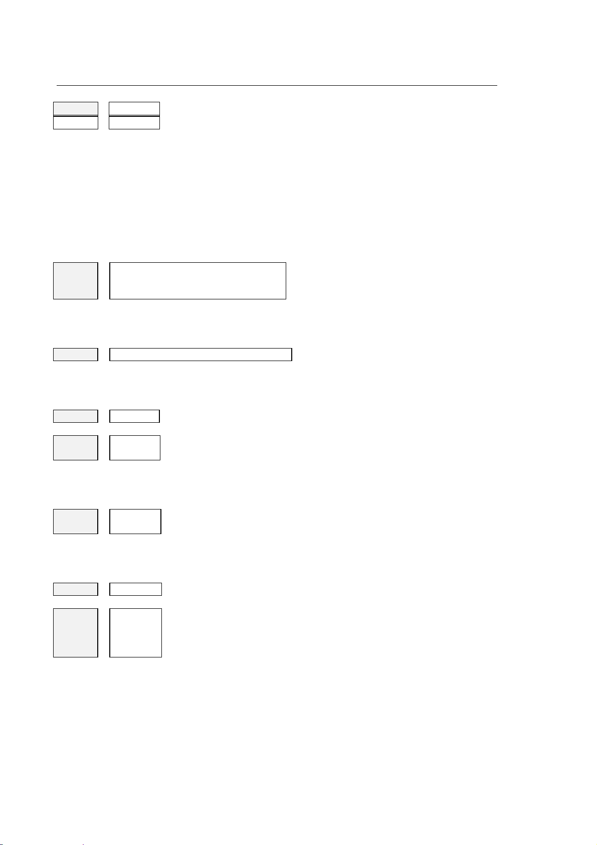
Chapter 3
User Interface
RAP: 0.00000
100.0% xxxxxx
Depending on the selected mode, this area displays rapid or manual
rate information:
RAP: this label is displayed when the system is in AUTO mode. In
manual mode this label will be MAN.
(0.0000) manual (MAN) or rapid (AUTO) rate in 5.5 format.
(100.00%) manual or rapid speed override.
(xxxxxx) current manual or rapid rate in 5.5. format.
When the rapid rate override function is active, the field name is
displayed in reverse.
G: 00 80 99 40 27
90 71 17
94 97
Active G codes: this field displays an active G code for each of the
configured modal groups. For further information about this topic refer to
the Programming Manual.
M: xx xx xx xx
Active M codes: this field displays an active M code for each of the
configured modal groups. For further information about this topic refer to
the Programming Manual.
JOG: 0.00000
ACT: Txx.xx
NXT: Txx.xx
d: 0.000000
Z: 0.000000
Value of the increment defined for manual incremental moves.
Number of the tool mounted on the spindle and of the active offset
associated to it.
The T word, which identifies the tool, is followed by two numerical
codes separated by a point. The code to left of the point is the tool
number. The code to right of the point is the tool offset number.
Number of the next tool to be mounted on the spindle and of the
active offset associated to it.
The T word, which identifies the tool, is followed by two numerical
codes separated by a point. The code to left of the point is the tool
number. The code to right of the point is the tool offset number.
Tool diameter.
This field displays the length offset applied to the active tool axis,
which is typically the spindle axis. It is calculated by multiplying the
value written in the tool offsets table by the configured direction with
the opposite sign.
3-14 10 Series CNC User Manual (15)
Page 63
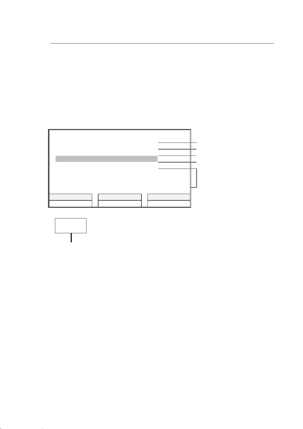
Chapter 3
User Interface
Part program data area
In this area are visualized the data relative to the running part program. On these rows it is not
possible to modify the program.
Each part program block will occupy one or two rows according to its length.The sequence is the
following: the part program block that has been run, the running one highlighted in reverse, then
the block that hasn't been run yet.
The part program instructions will slide upwards as they will be run.
The following figure shows a possible example of a running part program visualization:
PROGRAMS: MAINPROG SUB1 SUB2 program and subroutines
reserved for the DIS instruction
N26 S2000 F200 T3.03 executed block
N27 (UTO,1,X30,Y22) block in execution
N28 (ROT,20) subsequent block
N29 G81 R-90 Z-110 M3
N30 X25 Y25 blocks to go
N31 X40 Y10
POS DISPLAY NEXT DISPLAY SELECT PROCESS
AUTO MANUAL PART PROGRAM
IMPORTANT
If the control manages more than 6 configured axes, 7-n lines will be reserved
for displaying program blocks. n is any number of axes greater than 6.
In case of nine configured axes, for the part program run block only the first
row is reserved, therefore the longest blocks of 80 characters are truncated.
The meaning of the parameters displayed in the program blocks is explained in the Programming
Manual. The contents of the first display line are as follows:
PROGRAMS The first name on the line is the main program name. Subsequent names
are subroutine names. Though a program or subroutine name can be up to
48 characters long, only the first 12 characters will be displayed on this line.
When a subroutine becomes active, its name is displayed after the name of
the calling program or subroutine. This means that the first displayed
subroutine has the lowest nesting level.
10 Series CNC User Manual (15) 3-15
Page 64

Chapter 3
User Interface
Large font display
This screen displays some axes parameters using a large video font, which permits the operator to
read the axes coordinates from a certain distance. It is a full screen that can be invoked by
pressing the NEXT DISPLAY softkey. The layout of this screen is as follows:
Parameters are displayed in the current unit of measure (mm/inches), which depends on whether
G70 or G71 is active.
PROCESS CONTROLLED: 1 CAPS ON SCREEN 1 OF 4 TIME: 9:35:00
PROCESS: 1
[mm]
L X
M Y
Z
A
MACHINE
-175.34096
27.08432
0.00000
0.00000
S
S%
F
F%
RAP
RAP%
:
0.000
:
100.0%
:
1000.00000
:
62.5%
:
1000.00000
:
125.0%
B
POS DISPLAY NEXT DISPLAY SELECT PROCESS ENLARGE HELP
AUTO MANUAL PART PROGRAM VARIABLES OEM
MACHINE SETUP TABLES DIAGNOSTICS UTILITY
0.00000
Large font display
JOG INC
:
0.00000
3-16 10 Series CNC User Manual (15)
Page 65

Chapter 3
User Interface
Fields present on left hand side of screen in large font display
The left hand side of the screen is made up of 6 lines, in which the same parameters shown on the
first two columns of the axes data area of the main screen are displayed in a large font. The
meaning of these parameters is discussed in the "Main Screen" section.
unit of measure
type of axis
coordinate
axis name
mirror machining
marker
locked axis marker
Left hand side of the screen detailed in enlarged view
10 Series CNC User Manual (15) 3-17
Page 66

Chapter 3
User Interface
Fields present on right hand side of screen in large font display
The right hand half of the screen displays the following information:
PROCESS Is the number of the selected process.
S Is the spindle speed or the constant surface speed (CSS) in 6.3 format. CSS is
used when an open loop is programmed.
S% Percentage spindle speed override.
F Programmed feedrate in 5.5 format.
F% Percentage feedrate override.
RAP Depending on the selected mode (AUTO or MANUAL) this area displays the
following information:
RAP this label indicates that the system is in AUTO mode. The field displays
the rapid rate.
MAN this label indicates that the system is in MANUAL mode. The field
displays the manual rate.
RAP % This field is related to the preceding one and its label varies accordingly.
When the system is in AUTO mode (RAP%) the field displays the percentage
rapid override.
When the system is in MANUAL mode (MAN%) the field displays the percentage
manual override.
JOG INC Programmed incremental jog for the selected axis.
NOTE:
S, F and MAN/RAP are displayed in reverse when the relevant function is active.
3-18 10 Series CNC User Manual (15)
Page 67

Chapter 3
User Interface
Configurable screen pages
10 Series offers the application designer the possibility to personalise screen pages to satisfy
specific application needs. These screens can be created during system configuration by arranging
the pre-defined system and logic elementary quadrants in non-standard layouts.
Each configurable screen has four 10x39 quadrants. Elementary quadrants may be enlarged to
occupy the full screen by pressing the ENLARGE softkey (refer to the 'Enlarging an elementary
quadrant' section). The figure below shows a typical four quadrant screen.
PROCESS CONTROLLED: 1 CAPS ON SCREEN 1 OF 4 TIME: 9:35:00
PROC MODE STATE EXECUTING
AXIS WORK PROGRAMMED
1 AUTO IDLE MAIN-PROC
X 10.00000 10.00000
Y 20.00000 20.00000
Z 3.00000 3.00000
S RPM: 10.000 JOG INCR 0.00000
AUTO :STEP OPT STOP BLOCK DELETE
FEED BYPASS RETRACE
FEED MMPM: 0.0000 87.5% 0.00000
RAP : 0.0000 100.0% 4472.1361
SPEED RPM : 100.00 112.5% 0.000
PROGRAM :MAINPROG N6 2
SUB-PROG : SUB1 N
POS DISPLAY NEXT DISPLAY SELECT PROCESS ENLARGE HELP
AUTO MANUAL PART PROGRAM VARIABLES OEM
MACHINE SETUP TABLES DIAGNOSTICS UTILITY
PROGRAM: MAIN-PROG PROCESS: 1
ACTIVE SUBPROGRAM: SUB1
N6X10Y20
N7G1Z-.2F2000
N8G1X340
N9GZ2
N10X324Y50
N11G1Z-.2
N12X329
Example of configurable screen page
NOTE:
Distances are displayed in the unit of measure --mm or inches-- selected for the process
associated to the elementary quadrant. The unit of measure will remain visualised and will be
updated each time the system shifts between G70 and G71.
The screens that visualise the Realtime data (axes position, feed…) are updated only if the
information to visualise concern the selected process.
Example:
If in the small screen the axes of process 2 and the controlled process is number 1, the quote
WORK (ABSOLUTE,MACHINE..) will not be updated in Realtime, but only when in process 2 some
significative variations take place (es.end block execution…)
10 Series CNC User Manual (15) 3-19
Page 68

Chapter 3
User Interface
Here is a description of the pre-defined elementary quadrants that can be used for customising
video screens.
System status (SYS_STA)
This quadrant displays information about the system status and indicates the active process. The
meaning of its fields is as follows:
PROC MODE STATE EXECUTING
1 AUTO IDLE MAIN-PROG
PROC Number of the selected process.
MODE Current operation mode (AUTO or MANUAL).
STATE Current process state. Some states are allowed only in AUTO mode; others
occur in MANUAL mode or are allowed in either mode, as shown in the table
below. For more information about them, refer to the description of operations
that can be performed in each state later in this chapter.
STATE AUT MAN MEANING
IDLE
IN CYCLE
RUN
CYCLE STOP
zz
z
z
The process is waiting for a command.
The process is executing a part program or an
MDI command.
The process is executing a manual move.
z
The execution of a part program or an MDI
command has been interrupted and the
process is in stand-by.
HOLD
3-20 10 Series CNC User Manual (15)
The execution of the manual move has been
z
interrupted with the CYCLE STOP pushbutton
and the process is in stand-by.
Page 69

STATE AUT MAN MEANING
The execution of the part program has been
interrupted with the CYCLE STOP pushbutton.
When switched to MANUAL mode the system
RUNH
zz
shifts from CYCLE STOP to HOLD. If one or
more axes are jogged, the message turns to
RUNH and both the CYCLE START and the
CYCLE STOP pushbuttons are on. RUNH
tells the operator that a move is in progress.
If the CYCLE STOP pushbutton is pressed
with the system in HOLD or CYCLE STOP,
HRUN
zz
the system state shifts to HRUN, which means
that the process is ready to resume the
interrupted process. The CYCLE STOP lamp
turns off and the process remains in stand-by
until you re-press CYCLE START.
Chapter 3
User Interface
RESET
WAIT
INPUT
ERROR
EMERGENCY
zz
Indicates that the RESET pushbutton has
been pressed and that the process is being
cleared.
zz
The process is waiting to be synchronised with
another process.
zz
Indicates that the process is waiting for a
manual data input, i.e. a data entry window is
open.
zz
Indicates that the process has detected an
error during execution. The error can be
handled by the part program or lock the
process.
zz
The system has detected an error that
requests an intervention of the operator. The
error is described by an explanatory (refer to
the list of Emergency Messages in Appendix
A).
EXECUTING Process in execution. In AUTO mode this field displays the first 12 characters of
the name of the part program in execution. In MANUAL mode this field may
display the HOME, JOG INCR, JOG RETURN or HANDWHEEL submodes.
10 Series CNC User Manual (15) 3-21
Page 70

Chapter 3
User Interface
Axes position (AXES_POS)
This quadrant provides the current machine coordinates and the programmed coordinates
calculated by the control.
[mm] PROCESS: 1
AXIS WORK PROGRAMMED
X
Y
Z
S RPM: 100.000 JOG INC: 0.00000
PROCESS Displays the process number associated to the quadrant.
AXIS Displays up to 6 axes. To make a manual move select the axis with the
[up/down arrow keys].Locked axes are marked by the L word, whereas
mirroring axes are marked by the M word.
WORK Specifies the type of data displayed for each axis. The labels of this field, which
can be selected by pressing the POS DISPLAY softkey, are: WORK,
MACHINE, TO GO, ERROR or ABSOLUTE.
Axes coordinates are displayed in the 7.3, 6.4, 5.5 or 5.3 format, according to
the AMP configuration. They are expressed in the current measuring unit of the
process, which also appears on display.
PROGRAMMED Last programmed or input axis coordinate. It is a 10 digit number in the 7.3, 6.4
or 5.5 format.
10.00000
20.00000
3.00000
10.00000
20.00000
3.00000
S Spindle speed in 6.3 format. The field shows the unit of measure followed by
the current spindle speed (or the constant surface speed --CSS-- programmed
for an open loop control). The unit of measure may be:
RPM revolutions per minute
MPM meters per minute (for the tool cutter)
FPM feet per minute (for the tool cutter)
JOG INC Actual increment for jog moves expressed in 5.5 format.
3-22 10 Series CNC User Manual (15)
Page 71

Program display (PRG_DISP)
This quadrant displays information about the state of the part program in execution.
Chapter 3
User Interface
PROGRAM:MAIN-PROG
ACTIVE SUBPROGRAM: SUB1
N6X10Y20
N7G1Z-.2F2000
N8G1X340
N9G72
N10X324Y50
N11G1Z-.2
N12X329
PROGRAM This field displays the first 12 characters of the name of the part
program in execution (A program name can be up to 48 characters
long).
PROCESS Displays the number of the process associated to this screen.
ACTIVE SUBPROGRAM Displays the name of the current subroutine, which is the one
having the lowest nesting level. Although a program name can be
up to 48 characters long, only the first 12 are displayed.
The displayed part program lines are as follows:
PROCESS: 1
N6X10Y20 executed block
N7G1Z-.2F2000 block in execution
N8G1X340 subsequent block
N9G72
N10X324Y50 blocks to go
N11G1Z-.2
N12X329
NOTE:
The part program blocks that are longer than 40 characters are truncated.
10 Series CNC User Manual (15) 3-23
Page 72

Chapter 3
User Interface
Process status (PROC_STA)
This quadrant provides information about the process.
AUTO : STEP [mm] PROCESS: 1
OPT-STOP BLOCK-DELETE FEED-BYPASS RETRACE
F MMPM : 0.0000 87.5 % 0.00000
RAP : 0.0000 100.0 % 0.00000
S RPM : 0.000 100.0 % 0.000
PROGRAM : XXXXXX N : XXX
RPT :
SUB-PROG : XXXXXX N : XXX
RPT :
PROCESS Displays the number of the process associated to the quadrant.
AUTO Current mode (AUTO or MANUAL). Displayed data vary with the selected
mode:
AUTO BLK/BLK, MDI, OPT STOP, BLOCK DELETE, FEED BY
PASS, RETRACE
MANUAL JOG RETURN, JOG INCR, HOME, JOG+, JOG-, RETRACE,
HANDWHEEL.
F MMPM Displays the following information about the feedrate:
F
MMPM : 0.0000 87.5 % 0.00000
| | | |
unit of
measure
programmed
feedrate
in 5.5 format
override
percentage
current
feedrate
The units of measure for the feedrate are:
MMPM millimeters per minute
MMPR millimeters per revolution
IPM inches per minute
IPR inches per revolution
When the feedrate override function is active, the label of this field is
displayed in reverse.
3-24 10 Series CNC User Manual (15)
Page 73

User Interface
RAP This field displays feedrate information in MANUAL or RAPID mode.
For manual moves the displayed data are as follows:
MAN : 0.0000 100.0 % 0.00000
| | | |
manual move manual rate in
5.5 format
override
percentage
current manual
rate
For rapid moves the displayed data are as follows:
RAP : 0.0000 100.0 % 0.00000
| | | |
rapid move rapid rate in
5.5 format
override
percentage
current rapid rate
When the manual or rapid rate override function is active, the label of this
field is displayed in reverse.
Chapter 3
S RPM This field displays the following spindle speed data:
S
RPM : 100.000 100.0 % 0.00000
| | | |
unit of
measure
programmed
spindle speed
in 6.3 format
override
percentage
current spindle
speed
The spindle speed units are as follows:
RPM revolutions per minute
MPM meters per minute (for the tool cutter)
FPM feet per minute (for the tool cutter)
When the spindle speed override function is active, the label of this field is
displayed in reverse.
PROGRAM This field displays the first 12 characters of the name of the part program in
execution (A program name can be up to 48 characters long).
SUB-PROG Displays the name of the current subroutine, which is the one having the
lowest nesting level. Although a program name can be up to 48 characters
long, only the first 12 are displayed.
RPT Specifies the repeat level for the main program and the subroutines.
N Current block number.
10 Series CNC User Manual (15) 3-25
Page 74

Chapter 3
User Interface
Programmed code state (CODE_STA)
This quadrant provides information about the T, G and M codes written in the part program.
PROCESS: 1
T : ACTIVE 001 OFFSET: 002
NEXT 002 OFFSET: 028
G : 00 80 99 40 27 90
71 17 94 97
M : M00 M06 M19 M50
PROCESS Displays the number of the process associated to this screen.
T Information about T codes is arranged on two lines, one for the current tool and
one for the subsequent tool, as shown in the figure below:
current tool number current tool offset
| |
T : ACTIVE 001 OFFSET: 002
NEXT 002 OFFSET: 028
| |
programmed subsequent tool
to be mounted on the spindle
subsequent tool
offset
G Active G code for each of the 15 modal groups.
M Active M code for each modal group. Modal groups must be defined during
process configuration.
3-26 10 Series CNC User Manual (15)
Page 75

Axes offsets (AXIS_OFF)
This quadrant provides information about the axes offsets.
[mm] PROCESS: 1
AXIS ORIGIN SCALING %
X 1T
Y 2I 60.0
ROTATION :
XY-26.000
Chapter 3
User Interface
PROCESS Displays the number of the process associated to the quadrant.
AXIS Axis name. This field may display up to 6 axes associated to the process.
ORIGIN Displays the origin types associated to the axes. The words in this field may be:
T for temporary origins
I for incremental origins
SCALING % Percentage reduction of the axis scale (if active).
ROTATION Displays the axes of the interpolation plane and the rotation angle formed by them.
PLUS quadrants (LOGQUAD1,LOGQUAD2, LOGQUAD3, LOGQUAD4)
These elementary quadrants may be defined by the OEM operator and are handled by the
machine logic. They can be customised through the PLUS logic or the ASSET language and then
incorporated to configurable 4-quadrant screens similar to the ones described in the previous
section.
Selecting a screen
When the NEXT DISPLAY softkey is pressed, the video screens are displayed in the sequence
established by the OEM during system configuration. This sequence can be repeated on a cyclic
basis.
10 Series CNC User Manual (15) 3-27
Page 76

Chapter 3
User Interface
Enlarging an elementary quadrant
Each of the quadrants in a configurable screen can be enlarged to full screen size. The procedure
is as follows:
1. Select the configurable screen that includes the quadrant by pressing the NEXT DISPLAY
softkey as many times as necessary.
2. Select the elementary quadrant with the [PgUp] or [PgDn] keys. The background of a selected
quadrant becomes light. [PgUp] makes the light background move from quadrant to quadrant
counterclockwise, whereas [PgDn] makes the light background move from quadrant to
quadrant clockwise.
3. Press ENLARGE.
If ENLARGE is not pressed in a few seconds, the quadrant background turns dark again and the
quadrant cannot be enlarged.
NOTES:
• When the quadrant is enlarged using the ENLARGE key all the lower cases will be converted to
upper cases.
• The ENLARGE function is not available for PLUS quadrants.
3-28 10 Series CNC User Manual (15)
Page 77

Chapter 3
User Interface
Directory of Programs screen
By pressing the PART PROGRAM softkey it is possible to display the directory of programs,
whose layout is as follows:
PROCESS CONTROLLED: 1 CAPS ON SCREEN 1 OF 4 TIME: 9:35:00
PROC: 1 IDLE AUTO OPT STOP RETRACE
Current directory : PROGRAM
LAST USED PART PROGRAM (S)
PROGRAMNAME:
COPY DELETE RENAME HELP
EDIT SELECT DIR DIRECTORY DEACTIVATE ACTIVATE
PP MANAGEMENT
This screen permits to select a part program that can be used in the following operations:
• writing or editing (by means of the Line Editor or the Graphic Editor)
• program management
• activation/de-activation.
NOTE:
For a complete description, see the chapter 10 "Part Program File Manager".
10 Series CNC User Manual (15) 3-29
Page 78
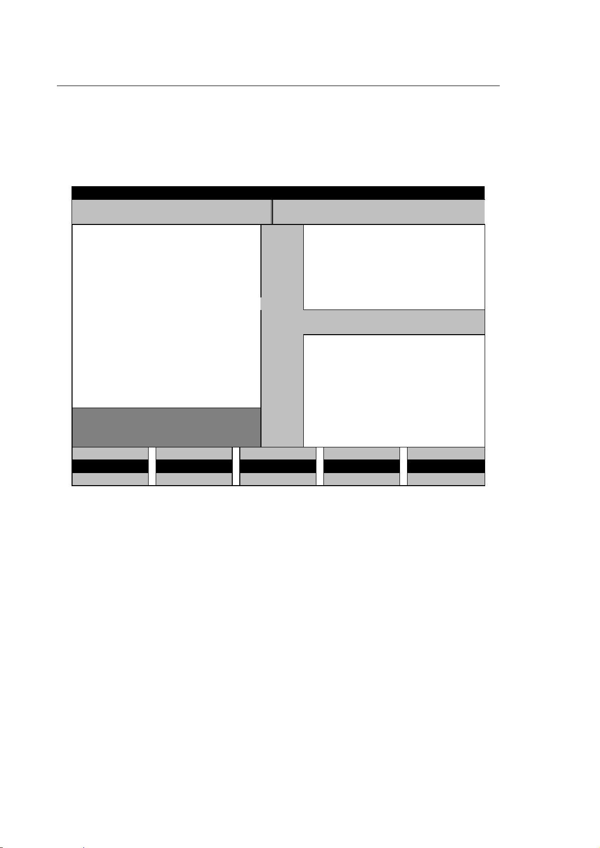
Chapter 3
User Interface
Additional data windows
In addition to the data provided by the main screen and the configurable pages, the operator can
request, display or receive further information on additional windows. These windows may
temporarily overlap the current display page or open on a reserved area. In some cases they are
used by the system for visualising messages for the operator.
STATUS LINE
SYSTEM AND PART PROGRAM WINDOW PLUS MESSAGES WINDOW
SMALL HELP WINDOW
MAIN SCREEN AREA
F
HELP WINDOW
ULL
DATA ENTRY WINDOW
MDI INPUT LINE
10 Series permits to visualise as many as six additional windows. If opened simulataneously, the
system applies a priority rule, i.e. the top priority window will cover all the others. System, part
program and PLUS message windows are not assigned a priority level because they are displayed
on a reserved area.
3-30 10 Series CNC User Manual (15)
Page 79

The table below lists the additional windows arranged on a priority basis.
Chapter 3
User Interface
1 Small Help window
2 Data entry window
3 Full Help window
4 Manual Data Input line
5 PLUS message window
6 System and part program
message window
This window may be opened with the HELP softkey when
a data entry window is active. It provides information
about the data entry window.
The system opens this window for the operator to write,
edit or confirm parameters. Data entry windows may
have differnt sizes, dending on the number of
parameters.
This 20x40 window can be opened with the HELP softkey
when no data entry window is active. (Otherwise, only a
small Help window can be activated).
This 128 line is used for writing program blocks on the
keyboard.
This window is not subject to the priority rule. It is a
39 character field used by the system for displaying
PLUS messages.
This window is not subject to the priority rule. It is a
39 character field used by the system for displaying
system and part program messages.
Certain PLUS warnings and error messages are displayed on the PLUS window. Other PLUS logic
messages appear on the LOGIC MAN screen (if configured).
Process or PLUS error messages may be displayed even when softkeys such as EDIT are active.
10 Series CNC User Manual (15) 3-31
Page 80

Chapter 3
User Interface
General rules about data entry windows
Data entry operations must be performed exclusively within a data entry window. These windows,
which may be invoked by pressing a softkey, are the only tool the operator can use for entering
data in the system.
The figure below illustrates a typical data entry window:
PROBE SET-UP [mm]
APPROACH TOLERANCE : 5.00000
SAFETY TOLERANCE : 5.00000
MEASURING FEED : 100.00001
HORIZONTAL SHIFT : 0.00000
VERTICAL SHIFT : 0.00000
Each window is made up of fields that contain parameters, file names, device names, etc. When
filling in these fields you must follow a series of rules that apply to all data enty windows.
Entries must be written in the legal format.
In long real fields the allowed format is a number having up to 10 digts plus the sign and the
decimal point.
This long real format is not the same as the long real format used in program blocks (refer to the
Programming Manual). If the long real format is assigned to the data entry window by the program
and overflows the window field, an E will be displayed to indicate the error condition.
NOTE:
Numerical parameter values are expressed in the default unit of measure configured for the
process in AMP. This unit of measure is also displayed on the window.
3-32 10 Series CNC User Manual (15)
Page 81

Chapter 3
User Interface
When the window appears, the cursor is on the most right character of the field. Input characters
are displayed as the cursor moves to the left. To make an entry you must use the following function
keys:
KEY FUNCTION
Moves the cursor to the right or to the left inside the field.
Moves the cursor from field to field.
Displays the previous page of a data entry window having multiple
pages.
Displays the subsequent page of a data entry window having multiple
pages.
Deletes the character on which the cursor is positioned.
Deletes the character to the left of the cursor.
Toggles between overwrite and insert modes.
Moves the cursor to the subsequent field.
Aborts the current data entry window.
Confirms the current data entry window.
10 Series CNC User Manual (15) 3-33
Page 82

Chapter 3
User Interface
A data entry window can be aborted at any moment with [Esc] or [Enter].
TO ABORT A WINDOW . . . PRESS . . . DATA WILL BE. . .
without saving the alterations [Esc] lost
confirming the entries/alterations [Enter] saved
NOTE:
The contents of the data entry window can also be confirmed by pressing the softkey that invoked
the window. Data entry windows having multiple pages may be confirmed by pressing [PgUp] or
[PgDn].
3-34 10 Series CNC User Manual (15)
Page 83

Chapter 3
User Interface
SOFTKEYS
There are 5 function keys ([F5] ÷ [F9]) located at the bottom of the operator panel which are used
for performing functions directly. The functions depend on the menus displayed at the bottom of the
screen just above the softkeys (see the figures of the operator panels in the "Operator Panel"
section of chapter 1).
Each menu is made up of three softkey lines. The functions associated to the softkeys at any one
time are those of the active menu line. This line is highlighted by the cyan bar, which can be shifted
cyclically from line to line by pressing the fixed key to the right of the softkeys. When a menu is
displayed for the first time the active line is the middle one.
The function of the fixed keys is as follows:
This key permits to return to the previous softkey menu. Press it to fastly
return to the machining environment and display the main screen. The
current task is temporarily suspended but remains active.
This key permits to move the highlighting bar from one softkey menu line to
the next.
The color of the softkey label varies according to the softkey status:
WHITE the softkey is available for activation
YELLOW the softkey has been pressed or is lit to indicate a certain mode.
BLACK the softkey is not available, i.e. cannot be activated.
10 Series CNC User Manual (15) 3-35
Page 84

Chapter 3
User Interface
Softkey-driven menus are organized hierarchically, i.e. a softkey may invoke a sub-menu, some of
whose softkeys may invoke other sub-menus, and so on. The complete softkey tree is shown in the
figure that follows:
PP. MANAGEMENT
At power up the system visualises the main softkey menu, which allows access to all of the system
resources.
3-36 10 Series CNC User Manual (15)
Page 85

Chapter 3
User Interface
With the exception of the Diagnostics, Part Program and Utility menus discussed later in this
chapter, the first softkey line in the machining environment remains unchanged even when other
submenus are invoked. The first softkey line permits to select general visualisation features, as
shown in the figure below:
POS DISPLAY NEXT DISPLAY SELECT PROCESS ENLARGE HELP
XXX XXX XXX XXX XXX
XXX XXX XXX XXX XXX
The sections that follow provide a short description of the functions available with the first two
submenu levels. The third level is analysed in the context of the relevant operating procedures.
10 Series CNC User Manual (15) 3-37
Page 86

Chapter 3
User Interface
Main menu
POS DISPLAY NEXT DISPLAY SELECT PROCESS ENLARGE HELP
AUTO MANUAL PART PROGRAM VARIABLES OEM
MACHINE SET-UP TABLES DIAGNOSTICS UTILITY
POS DISPLAY This softkey permits to select the type of visualised data for the axes
configured in the process. Allowed options are: ABSOLUTE, MACHINE,
WORK, TO GO, ERROR.
NEXT DISPLAY This softkey displays the next video page in the current sequence.
SELECT PROCESS Through an input window, this softkey allows to select one of the
processes configured in AMP.
SELECT PROCESS
Process number:
Press [Ctrl] [P] to select configured processes sequentially.
ENLARGE This softkey enlarges the quadrant to full screen size (21 lines x 80
columns). For more information about the procedure, please refer to the
"Enlarging an elementary quadrant" section in this chapter.
HELP This softkey opens a context-sensitive help window. The visualised
information varies with the active softkey and/or the open data entry
window.
3-38 10 Series CNC User Manual (15)
Page 87

Chapter 3
User Interface
Auto
This menu, which can be invoked with the AUTO softkey, offers the following commands:
POS DISPLAY NEXT DISPLAY SELECT PROCESS SEARCH MEMORY HELP
MDI BLK/BLK BLOCK MODIFY MACHINE PLOT DRY RUN
XXXXXXXX+ XXXXXXXX- OVERRIDE SEL STRING SEARCH EXEC FROM:TO
MDI Opens a data entry window for an MDI (Manual Data Input) operation
such as writing a program block from the keyboard. Press [Enter] to
confirm the input block. Press CYCLE START to execute the block if the
process is in IDLE state.
BLK/BLK Selects block by block execution mode. To execute the selected block
press CYCLE START.
BLOCK MODIFY Permits to edit the current program block. This softkey is enabled only
after a part program has been selected and the MDI mode is active.
MACHINE PLOT This softkey enables an application that graphically visualises the tool
path during the machining cycle. For more information about this
application refer to chapter 12 “Machine Plot”.
SEARCH MEMORY To enable/disable memory searching function.
DRY RUN Enables/disable the DRY RUN feature on the active program.
XXXXXXXX + Applies the feedrate, spindle speed or rapid override percentage selected
with the OVERRIDE SEL. softkey.
Each time you press this softkey the programmed increment is applied
to the feedrate, spindle speed or rapid.
XXXXXXXX - Applies the feedrate, spindle speed or rapid override percentage selected
with the OVERRIDE SEL. softkey.
Each time you press this softkey the programmed decrement is applied
to the feedrate, spindle speed or rapid.
NOTE:
XXXXXXXX + and XXXXXXXX - change according to the name shown in the table below
depending on the type of override desired. Changeover from one quantity to the next is performed
cyclically each time the OVERRIDE SEL softkey is pressed:
XXXXXXXX + XXXXXXXX -
FEEDRATE + FEEDRATE -
SPND OVER + SPND OVER -
RAPID OVER + RAPID OVER -
10 Series CNC User Manual (15) 3-39
Page 88

Chapter 3
User Interface
OVERRIDE SEL. Selects the parameter to be overridden (FEEDRATE, SPND OVER or
RAPID OVER) and alters the softkey label accordingly.
STRING SEARCH Searches for a string of characters in the current part program. When this
softkey is pressed the system opens a data entry window for the operator
to key in the string. This softkey is enabled only after a part program has
been selected.
EXEC FROM:TO This softkey selects the start and end blocks for partial exceution of the
program selected.
This softkey is enabled only after a part program has been selected.
3-40 10 Series CNC User Manual (15)
Page 89

Chapter 3
User Interface
Manual
This menu, which can be invoked with the MANUAL softkey, offers the following options:
POS DISPLAY NEXT DISPLAY SELECT PROCESS HELP
HOME JOG INCR JOG RETURN HPG MANUAL SETUP
XXXXXXXX+ XXXXXXXX- OVERRIDE SEL JOG DIR SET ORIG./TOOL
HOME Enables axes homing. To start homing the selected axis it is necessary to
press the CYCLE START pushbutton.
JOG INCR Enables incremental manual moves. To move the selected axis by an
increment press the CYCLE START pushbutton. See chapter 6 “Axes
Jogging and Stop Functions” for more details.
JOG RETURN Enables return to the profile after a manual move. See chapter 6 “Axes
Jogging and Stop Functions” for more details.
HPG Enables handwheel management by the logic.
MANUAL SETUP Opens a data entry window for defining the jog increment and the jog
return mode. On special occasions it also permits to remove the tool from
the part (see chapter 6 “Axes Jogging and Stop Functions”).
XXXXXXXX + Applies the feedrate, spindle speed or rapid override percentage selected
with the OVERRIDE SEL. softkey.
Each time you press this softkey the programmed increment is applied
to the feedrate, spindle speed or rapid.
XXXXXXXX - Applies the feedrate, spindle speed or rapid override percentage selected
with the OVERRIDE SEL. softkey.
Each time you press this softkey the programmed decrement is applied
to the feedrate, spindle speed or rapid.
NOTE:
XXXXXXXX + and XXXXXXXX - change according to the name shown in the table below
depending on the type of override desired. Changeover from one quantity to the next is performed
cyclically each time the OVERRIDE SEL softkey is pressed:
XXXXXXXX + XXXXXXXX -
FEEDRATE + FEEDRATE -
SPND OVER + SPND OVER -
RAPID OVER + RAPID OVER -
10 Series CNC User Manual (15) 3-41
Page 90

Chapter 3
User Interface
OVERRIDE SEL. Selects the parameter to be overridden (FEEDRATE, SPND OVER or
RAPID OVER) and alters the softkey label accordingly.
JOG DIR Selects the jogging direction. When this softkey is pressed the + or - sign
appear on the label and the axis jogging direction changes accordingly.
SET ORIG./TOOL This softkey has two functions: it sets the origins and presets the tool.
SET ORIG. function:
Opens a data entry window for defining the origins and setting the
position of the specified axes to zero.
TOOL function:
Opens a data entry window for defining the axis name and entering the
tool tip coordinate. This function applies a new tool length to the tool
length offset of the current tool.
Part Program
This menu, which is enabled by the PART PROGRAM softkey, permits to access the part program
environment and enables the relevant softkeys.
COPY DELETE RENAME HELP
EDIT SELECT DIR DIRECTORY DEACTIVATE ACTIVATE
For further information, see Chapter 10 "Part Program File Manager".
3-42 10 Series CNC User Manual (15)
Page 91

Chapter 3
User Interface
Variables
This menu is enabled by the VARIABLES softkey. It offers softkeys dedicated to visualisation and
editing of several classes of variables. For more information about system parameters and
variables refer to the "Programming Manual".
POS DISPLAY NEXT DISPLAY SELECT PROCESS ENLARGE HELP
E VARIABLES SN VARIABLES USER VARIABLES H VARIABLES PLUS VARIABLES
FIND PAGE/IND SUBSTITUTE EVALUATE SC VARIABLES
E VARIABLES Opens a data entry window for defining E variables.
SN VARIABLES Opens a data entry window for defining Long Real (SN) system variables.
USER VARIABLES Opens a data entry window for defining the user variables defined during
the characterisation. These variables are listed in a single group even
when different variable names have been defined. At the end of the list
the system requests the name of the variable to be visualised.
H VARIABLES Opens the window of H variables for read only operations.
PLUS VARIABLES Opens the window for logic global variables.
FIND PAGE/IND Opens a data entry window for the page number and the index of the
variable on which the cursor must be positioned.
SUBSTITUTE Writes in the selected field of the data entry window the value of the last
expression calculated with EVALUATE.
EVALUATE Opens a data entry window to calculate an expression. In this calculation
it is possible to use variables. By pressing the SUBSTITUTE softkey the
result of the calculation can be written to the selected variable.
SC VARIABLES Opens a data entry window for Character (SC) system variables.
OEM
The menu activated by the OEM softkey permits to access and enable the softkeys defined by the
application designer. The names of these softkeys may be configured in the AMP and therefore is
application-specific.
POS DISPLAY NEXT DISPLAY SELECT PROCESS ENLARGE HELP
OEM 1-1 OEM 1-2 OEM 1-3 OEM 1-4 OEM 1-5
OEM 2-1 OEM 2-2 OEM 2-3 OEM 2-4 OEM 2-5
10 Series CNC User Manual (15) 3-43
Page 92

Chapter 3
User Interface
Machine Set-Up
The menu activted by the MACHINE SET-UP softkey permits to access a submenu of parameters
and softkeys that define the machine functions.
POS DISPLAY NEXT DISPLAY SELECT PROCESS ENLARGE HELP
DYNAMIC PARAM DYNAMIC LIMITS PROGRAM SET-UP BLOCK RETRACE PROBE SET-UP
REF SET ACCURACY TIME/DATE SET
The DYNAMIC PARAMS softkey opens a data entry window similar to the one below:
DYNAMIC PARAMETERS
ENABLE VFF (Y/N) :
G04 DWELL TIME :
SPINDLE LIMIT (RMP) :
% TAP RETRACT FEED (G84) :
Significance of the fields is as follows:
ENABLE VFF(Y/N) Enables/disables the servo algorithm with velocity feed forward.
When the algorithm is enabled, the tracking error will be closed on zero
(consistent with the gain of the servo loop configured in AMP) to reduce
the profile shaping error to the minimum.
When the algorithm is disabled, the axes are controlled with tracking error
only.
G04 DWELL TIME Defines the end-of-block dwell time (G04).
SPINDLE LIMIT (RPM) Defines maximum spindle speed.
Used in CSS - Constant Surface Speed - mode when spindle speed
depends on position of the master axis.
% TAP RETRACT FEED (G84)
Specifies the percentage of the feedrate applied to the retract phase of
the tapping cycle.
DYNAMIC LIMITS Opens a data entry window for defining the dynamic limits of the machine
in a contouring operation.
3-44 10 Series CNC User Manual (15)
Page 93

Chapter 3
User Interface
PROGRAM SET-UP Opens a data entry window permitting configuration of some parameters
conditioning the part program execution mode:
− Block delete
− Optional stop
− Feedrate bypass
− Rapid rate control
− Rotation
− Stock allowance
And for each axis configured:
− Stand still
− Mirror modes
− Scale
− Scale factor
BLOCK RETRACE Permits definition, if configured in AMP, of the machine path to be
performed backwards.
The softkey is enabled only if a program is selected and if the CYCLE
STOP pushbutton is pressed during execution.
The sequence of operations is as follows:
System in CYCLE STOP
− BLOCK RETRACE enabled
− Press CYCLE START; the system moves the axes backwards
towards the last point of the buffer.
Movements will be executed in consistency with the mode selected
(AUTO, BLK/BLK).
− To return to normal conditions, disable BLOCK RETRACE, exit from
CYCLE STOP mode and press CYCLE START.
PROBE SET-UP Opens a data entry window for setting all the probing parameters.
REF Opens a data entry window to establish axes references.
SET ACCURACY Defines accuracy parameters for circular interpolation.
TIME/DATE SET Opens a data entry window for setting the time with hh/mm/ss format and
the date with yy/mm/dd format.
10 Series CNC User Manual (15) 3-45
Page 94

Chapter 3
User Interface
Tables
The menu opened by the TABLES softkey permits to access the Table Editor and enables its
softkeys. See chapter 7 “Using Tables” for more information about this option.
BACKUP MEMORY RESTORE MEMORY MAGAZINE SETUP HELP
TOOL OFFSET USER ORIGIN TOOL DATA BASE
SELECT PROCESS SELECT MAGAZINE SET INCR USER TABLE EXIT
BACKUP MEMORY Makes a backup copy on the hard disk of the tables resident in the dual
port memory.
RESTORE MEMORY Restores the backup copy of the tables to the dual port memory.
MAGAZINE (Option) Permits to manage the Tool Magazine option. For more
information about the Tool Magazine please refer to the specific
documentation.
SETUP Allows configuration of the tables used by the table editor.
HELP Displays the Help page associated to the current data entry window or
softkey menu.
TOOL Permits to access and edit the Tools Table.
OFFSET Permits to access and edit the Tool Offset Table.
USER Permits to access and edit the User Table.
ORIGIN Permits to access and treat the contents of the Origins Table.
TOOL DATA BASE Permits to access and edit the Tool Data Base Table, which can be
enabled only with the Tool Magazine option.
SELECT PROCESS Permits to select the configured processes.
SELECT MAGAZINE Permits to select the Tool Magazine. For more information about this
option refer to its documentation.
SET INCR Permits to set an increment value.
USER TABLE Permits to configure and treat the contents of the User Table. See
chapter 8 “Table Editor Configurator” for details.
EXIT Exits from the Table Editor and returns to the main softkey menu.
3-46 10 Series CNC User Manual (15)
Page 95

Chapter 3
User Interface
Diagnostics
The menu enabled by the DIAGNOSTICS softkey permits access to the diagnostic functions.
HELP
SECURITY SYSTEM HISTORY DSI SRV CHAN SERVO MONITOR
SYSTEM SHUT DOWN
HELP Opens a Help page associated to the current data entry window or
softkey menu.
SECURITY Permits to create a hierarchy of system users having different levels of
access to the system resources. To each level corresponds a password
that allows to perform specific operations. See chapter 13 “DOS Shell” for
details.
SYSTEM HISTORY Enables the video screen the list of the last 200 system messages (errors
and service messages) displayed by the system in the chronological
sequence in which they occurred.
DSI SRV CHAN Enables the utility for the D.S.I axes parameter configuration.
SERVO MONITOR Permits to access the system Servo Monitor, a utility that can be broken
down into two main functions:
Parameter change: permits to edit certain axes parameters during
execution without using AMP or re-initialising the
system.
Oscilloscope: monitors and graphically displays the axis path
with the relevant following error.
SYSTEM SHUT DOWN This function is used to restart or shut down the system in a controlled
manner, closing currently open files and applications.
10 Series CNC User Manual (15) 3-47
Page 96

Chapter 3
User Interface
Utility
This menu is enabled by the UTILITY softkey. It permits to access the OEM environment and
enables the relevant softkeys.
AMP PLUS DOS SHELL PERIPHERAL HELP
AMP Permits to access the AMP environment, which is used for system
configuration.
PLUS Permits to access the PLUS environment, which is used for developing
the machine logic.
DOS SHELL Permits the OEM to handle files in the DOS environment.
PERIPHERAL Permits execution of the following operations:
− Configuration of the output device for the printer.
− Remote bootstrap configuration.
− Interlink configuration and activation to connect with a remote unit.
− If the MINI DNC option is present, activation of the network
configurator.
− Immediate connection of all environments configured as remote.
− Immediate connection of all services configured as remote.
HELP Opens a Help page associated to the current data entry window or
softkey menu.
3-48 10 Series CNC User Manual (15)
Page 97

Chapter 3
User Interface
OPERATOR CONSOLE
The Operator Console provides the operator with three control buttons for executing the CYCLE
START, CYCLE STOP and RESET commands, and a group of buttons and/or selectors for
changing the speeds of the axes and selecting the operating modes of the system.
If a system with a WinLink and/or BLink operator panel is used, an external Operator Console or
Pilot Panel is essential while the OPLink operator panel has a built-in Operator Console.
If WinMedia is used as Operator panel, it is indispensable to use an external Operator Console or
adopt the “WinMedia Operator Console” described in the following pages.
Nearly all the controls on the operator console duplicate functions performed by following specific
operating procedures in which the softkeys are used.
If an external operator console is installed, it must be defined by means of the machine logic
whether the commands executed on the pilot panel are to replace the equivalent system functions
completely (most common case) or whether they may be carried out in parallel. In the latter case,
measures must be taken to ensure that conflicting commands are not executed at the same time.
If the console built into the OPLink operator panel is used, the system automatically controls the
commands in parallel.
Operator Console Keys and Functions
As illustrated in the figure, on the right-hand side of the OPLink operator panel there are operator
console keys and the START, HOLD and RESET buttons, that is, the control buttons described in
the "Control Buttons" section at the start of this chapter.
A description of the keys and functions of the operator console built into the OPLink operator panel
is provided below.
10 Series CNC User Manual (15) 3-49
Page 98

Chapter 3
User Interface
Key for selecting the MANUAL MOVEMENT (JOG).
When this key or the MANUAL softkey on the main menu is pressed, the system automatically
activates continuous manual movement. A description of the keys that enable the operator to
execute the manual movement commands and the other related functions is provided below. For
further details on manual movements, see chapter 6 "Axes Jogging and Stopping Functions" of
this manual.
Enables incremental manual movement (JOG INCR softkey). When
the CYCLE START button is pressed as defined in the MANUAL
SET-UP input box, the incremental jog is performed on the selected
Jog increment
axis.
Enables the axis homing cycle (HOME softkey). When the CYCLE
START button is pressed, the homing procedure is executed on the
selected axis (see chapter 5 "Establishing Origins and Homing the
Home
Axes").
Speed change
Increment change
Jog direction change
Percentage change in the manual feed rate defined in the
configuration (FEEDMAN + and FEEDMAN - softkeys). When the [+]
and [-] keys are pressed alternately, the percentage change is
increased or decreased by 12.5%.
Change in the increment for incremental manual movement (JOG
INCR + and JOG INCR - softkeys). When the [+] and [-] keys are
pressed alternately, the value of the increment is increased or
decreased.
Selection of the direction of manual movement (JOG DIR +/-
softkeys). When the [+] and [-] keys are pressed alternately, the jog
direction changes from positive to negative or vice versa.
3-50 10 Series CNC User Manual (15)
Page 99

Chapter 3
User Interface
Key for selecting AUTOMATIC operating mode (AUTO softkey on the main menu).
When this key is pressed, the system automatically activates automatic execution of the
selected part program: all the blocks in the part program are executed without interruption. A
description of the keys for selecting the other execution modes and other functions of this
environment is provided below. For further details on this environment, see chapter 11 "Part
Program Execution" of this manual.
Block by block execution of the part program (BLK/BLK softkey).
When the CYCLE START button is pressed, the single selected block
is executed.
BLK/BLK
Opens the MDI input box for insertion of a program block from the
keyboard (MDI softkey). Execution of the block inserted starts when
the CYCLE START button is pressed, having confirmed the block by
MDI
pressing the Enter key.
Rapid traverse variation
Feed rate change
Spindle speed change
Percentage change in traverse speed defined in the configuration
(RAPID OVER + and RAPID OVER - softkeys). When the [+] and [-]
keys are pressed alternately, the percentage change is increased or
decreased by 12.5%.
Percentage change in the feed rate set in the part program with the
[F] operator (FEEDRATE + and FEEDRATE - softkeys). When the [+]
and [-] keys are pressed alternately, the programmed feed rate value
is increased or decreased by 12.5%.
Percentage change in the spindle speed set in the part program with
the [S] operator (SPND OVER + and SPND OVER - softkeys). When
the [+] and [-] keys are pressed alternately, the programmed spindle
speed value is increased or decreased by 5%.
10 Series CNC User Manual (15) 3-51
Page 100

Chapter 3
User Interface
Pilot Panel Selectors and Functions
The figure below shows the external operator console or Pilot Panel.
The following buttons are present on the right-hand side of the pilot panel
CYCLE STOP button
CYCLE START button
RESET button
The functions performed by these three buttons are described in the "Control Buttons" section at
the start of this chapter.
The commands associated with the pilot panel selectors are described below.
Speed
Controls the spindle speed override percentage and is
equivalent to the OVERRIDE SEL and SPND OVER+ / SPND
OVER- sequence. Spindle speed override percentages range
from 75% to 125% of the programmed value.
3-52 10 Series CNC User Manual (15)
 Loading...