


Integrated Amplifier
A-9000R
Instruction Manual
En
WARNING:
TO REDUCE THE RISK OF FIRE OR ELECTRIC SHOCK, DO NOT EXPOSE THIS APPARATUS TO RAIN OR MOISTURE.
CAUTION:
TO REDUCE THE RISK OF ELECTRIC SHOCK, DO NOT REMOVE COVER (OR BACK). NO USER-SERVICEABLE PARTS INSIDE. REFER SERVICING TO QUALIFIED SERVICE PERSONNEL.
WARNING |
|
AVIS |
RISK OF ELECTRIC SHOCK |
|
RISQUE DE CHOC ELECTRIQUE |
DO NOT OPEN |
|
NE PAS OUVRIR |
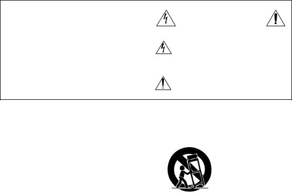
The lightning flash with arrowhead symbol, within an equilateral triangle, is intended to alert the user to the presence of uninsulated “dangerous voltage” within the product’s enclosure that may be of sufficient
magnitude to constitute a risk of electric shock to persons.
The exclamation point within an equilateral triangle is intended to alert the user to the presence of important operating and maintenance (servicing) instructions in the literature accompanying the appliance.
Important Safety Instructions
1.Read these instructions.
2.Keep these instructions.
3.Heed all warnings.
4.Follow all instructions.
5.Do not use this apparatus near water.
6.Clean only with dry cloth.
7.Do not block any ventilation openings. Install in accordance with the manufacturer’s instructions.
8.Do not install near any heat sources such as radiators, heat registers, stoves, or other apparatus (including amplifiers) that produce heat.
9.Do not defeat the safety purpose of the polarized or grounding-type plug. A polarized plug has two blades with one wider than the other. A grounding type plug has two blades and a third grounding prong. The wide blade or the third prong are provided for your safety. If the provided plug does not fit into your outlet, consult an electrician for replacement of the obsolete outlet.
10.Protect the power cord from being walked on or pinched particularly at plugs, convenience receptacles, and the point where they exit from the apparatus.
11.Only use attachments/accessories specified by the manufacturer.
En
12. Use only with the cart, stand, tripod, bracket, or table
specified by the manufacturer, or sold with the apparatus.
When a cart is used, use caution when moving the
cart/apparatus combination to
S3125A
avoid injury from tip-over.
13.Unplug this apparatus during lightning storms or when unused for long periods of time.
14.Refer all servicing to qualified service personnel. Servicing is required when the apparatus has been damaged in any way, such as power-supply cord or plug is damaged, liquid has been spilled or objects have fallen into the apparatus, the apparatus has been exposed to rain or moisture, does not operate normally, or has been dropped.
15.Damage Requiring Service
Unplug the apparatus from the wall outlet and refer servicing to qualified service personnel under the following conditions:
A.When the power-supply cord or plug is damaged,
B.If liquid has been spilled, or objects have fallen into the apparatus,
C.If the apparatus has been exposed to rain or water,
D.If the apparatus does not operate normally by following the operating instructions. Adjust only those controls that are covered by the operating instructions as an improper adjustment of other controls may result in damage and will often
require extensive work by a qualified technician to restore the apparatus to its normal operation,
E.If the apparatus has been dropped or damaged in any way, and
F.When the apparatus exhibits a distinct change in performance this indicates a need for service.
16.Object and Liquid Entry
Never push objects of any kind into the apparatus through openings as they may touch dangerous voltage points or short-out parts that could result in a fire or electric shock.
The apparatus shall not be exposed to dripping or splashing and no objects filled with liquids, such as vases shall be placed on the apparatus.
Don’t put candles or other burning objects on top of this unit.
17.Batteries
Always consider the environmental issues and follow local regulations when disposing of batteries.
18.If you install the apparatus in a built-in installation, such as a bookcase or rack, ensure that there is adequate ventilation.
Leave 30 cm (12") of free space at the top and sides and 10 cm (4") at the rear. The rear edge of the shelf or board above the apparatus shall be set 10 cm (4") away from the rear panel or wall, creating a flue-like gap for warm air to escape.
2

Precautions
1.Recording Copyright—Unless it’s for personal use only, recording copyrighted material is illegal without the permission of the copyright holder.
2.AC Fuse—The AC fuse inside the unit is not userserviceable. If you cannot turn on the unit, contact your Onkyo dealer.
3.Care—Occasionally you should dust the unit all over with a soft cloth. For stubborn stains, use a soft cloth dampened with a weak solution of mild detergent and water. Dry the unit immediately afterwards with a clean cloth. Don’t use abrasive cloths, thinners, alcohol, or other chemical solvents, because they may damage the finish or remove the panel lettering.
4.Power WARNING
BEFORE PLUGGING IN THE UNIT FOR THE FIRST TIME, READ THE FOLLOWING SECTION CAREFULLY.
AC outlet voltages vary from country to country. Make sure that the voltage in your area meets the voltage requirements printed on the unit’s rear panel (e.g., AC 230 V, 50 Hz or AC 120 V, 60 Hz).
The power cord plug is used to disconnect this unit from the AC power source. Make sure that the plug is readily operable (easily accessible) at all times.
For models with [POWER] button, or with both [POWER] and [ON/STANDBY] buttons: Pressing the [POWER] button to select OFF mode does not fully disconnect from the mains. If you do not intend to use the unit for an extended period, remove the power cord from the AC outlet.
For models with [ON/STANDBY] button only: Pressing the [ON/STANDBY] button to select Standby mode does not fully disconnect from the mains. If you do not intend to use the unit for an extended period, remove the power cord from the AC outlet.
5.Preventing Hearing Loss Caution
Excessive sound pressure from earphones and headphones can cause hearing loss.
6.Batteries and Heat Exposure Warning
Batteries (battery pack or batteries installed) shall not be exposed to excessive heat as sunshine, fire or the like.
7.Never Touch this Unit with Wet Hands—Never handle this unit or its power cord while your hands are wet or damp. If water or any other liquid gets inside this unit, have it checked by your Onkyo dealer.
8.Handling Notes
•If you need to transport this unit, use the original packaging to pack it how it was when you originally bought it.
•Do not leave rubber or plastic items on this unit for a long time, because they may leave marks on the case.
•This unit’s top and rear panels may get warm after prolonged use. This is normal.
•If you do not use this unit for a long time, it may not work properly the next time you turn it on, so be sure to use it occasionally.
For British models
Replacement and mounting of an AC plug on the power supply cord of this unit should be performed only by qualified service personnel.
IMPORTANT
The wires in the mains lead are coloured in accordance with the following code:
Blue: Neutral Brown: Live
As the colours of the wires in the mains lead of this apparatus may not correspond with the coloured markings identifying the terminals in your plug, proceed as follows: The wire which is coloured blue must be connected to the terminal which is marked with the letter N or coloured black.
The wire which is coloured brown must be connected to the terminal which is marked with the letter L or coloured red.
IMPORTANT
The plug is fitted with an appropriate fuse. If the fuse needs to be replaced, the replacement fuse must approved by ASTA or BSI to BS1362 and have the same ampere rating as that indicated on the plug. Check for the ASTA mark or the BSI mark on the body of the fuse.
If the power cord’s plug is not suitable for your socket outlets, cut it off and fit a suitable plug. Fit a suitable fuse in the plug.
For European Models
Declaration of Conformity
We, ONKYO EUROPE ELECTRONICS GmbH LIEGNITZERSTRASSE 6, 82194 GROEBENZELL, GERMANY
declare in own responsibility, that the ONKYO product described in this instruction manual is in compliance with the corresponding technical standards such as EN60065, EN55013, EN55020 and EN61000-3-2, -3-3.
GROEBENZELL, GERMANY
K. MIYAGI
ONKYO EUROPE ELECTRONICS GmbH
En
3
Features
•140 W/Ch (4 ohm, 20 Hz - 20 kHz, 0.05%, 2 Channels Driven, IEC)
•A WRAT (Advanced Wide Range Amplifier Technology)
•DIDRC (Dynamic Intermodulation Distortion Reduction Circuitry)
•Quad Push-Pull Amplification Design with Three-Stage Inverted Darlington Circuitry
•Symmetrical Layout of Power Stage
•Four Large 18,000 µF Capacitors
•Anti-Vibration Aluminum Panels for Front and Sides
•Side-mounted Circuit Board Construction to Reduce Vibration
•Separate Digital/Analog Circuitry
•Low-noise Static Display
•PLL Ultra-Low Jitter Technology
•Separate Wolfson 192 kHz/24-Bit DACs (WM8742) for L/R Channels
•Direct Mode
•Tone Control (Bass/Treble)
•Balance Control
•Independent Headphone Amplifier
•Discrete Phono Equalizer
•Phono Input (MM/MC)
•De-emphasis Function*1
•USB Digital Input for 192 kHz/24-Bit HD Audio from PC*2
•AES/EBU Balanced Digital Input with XLR Connector
•4 Digital Inputs (1 AES/EBU, 2 Coaxial and 1 Optical)
•Gold-Plated, Machined Solid Brass RCA Inputs
•Gold-Plated Large Speaker Posts
•Display Dimmer (Normal/Dim/Off)
*1 This function only applies to the following sampling rates: 32 kHz, 44.1 kHz, 48 kHz. Other rates are not supported.
*2 Playback of PC audio requires dedicated software that can be downloaded from the Onkyo web site. Audio signals of up to 32 bit can be input.
However, the resulting output will be equivalent to a quality of 24 bit.
En
4

Technologies
1.A WRAT (Advanced Wide Range Amplifier Technology)
The A-9000R employs a host of proprietary Onkyo technologies to ensure optimal audio performance.
–DIDRC (Dynamic Intermodulation Distortion Reduction Circuitry)
Since the advent of digital audio, the values of S/N (signal-to-noise) ratio have risen significantly. However, it is also recognized that in terms of perceived S/N, analog audio sources are not inferior to digital sources.
Generally, S/N measures the ratio when sound is and not produced, but takes no account of the noise generated during sound reproduction.
For a long time, Onkyo has focused and made extensive research on the S/N when sound is produced (dynamic S/N). Using a mechanism that captures the noise beyond audible range, it has been possible to determine that both dynamic S/N and perceived S/N aggravate during music reproduction.
Although frequencies above 20 kHz are beyond human hearing, it is well known that a beat can be perceived if different signals are overlapped at such frequencies.
During the analog audio era, no significant signals were entering beyond the audible range. However, the digital era has made recording beyond the audible range possible and the generated beat is now perceivable.
With Onkyo’s DIDRC technology, a new approach is introduced which prevents such beat from penetrating the audible range.
– Low Negative-Feedback Design
Conventional amplifiers make extensive use of negative feedback (NFB), whereby part of the output signal is re-input in order to improve the S/N ratio across a wide frequency range. However, too much NFB makes a system susceptible to counter-electromotive force from the speakers, resulting in a drop in perceived sound quality. To avoid this, Onkyo focuses on improving the frequency response and reducing distortion, without relying so much on NFB. We use a low negative-feedback design incorporating audiophile-grade, close-tolerance components, to achieve a frequency response, out to 100 kHz.
– Closed Ground-Loop Circuits
If an amplifier’s ground potential (voltage) fluctuates during playback, noise is likely to result. In an open-loop circuit design, where all circuits wire connected to the power supply via a single loop (as on many amplifiers), the noise is compounded. To avoid this, the A-9000R employs a sophisticated closed-circuit design in which each circuit has a separate link to the power supply. This helps to cancel individual circuit noise and keep the ground potential free of distortion.
–HICC (High Instantaneous-Current Capability)
When an amplifier outputs an audio signal, the connected speakers accumulate energy, reflex, and send energy back to the amplifier. The amplifier must then immediately cancel the speakers’ reflex energy and instantaneously send out the next signal. The same high current required to achieve this is also necessary to handle speaker impedance, fluctuations, which can force an amplifier to provide four to six times its usual current load. The A-9000R’s instantaneous current capability ensures that audio output is not affected by power limitations.
–Symmetrical Twin-Monaural Construction
Power devices for the left and right channels of the A-9000R are aligned symmetrically. Each channel has the same electrical and structural design, and signal pathways are uniform in length. This helps to minimize errors in stereophonic playback.
En
5

2.Quad Push-Pull Amplification Design with Three-Stage Inverted Darlington Circuitry
Three-Stage Inverted Darlington Circuitry brings greater efficiency to the A-9000R integrated amp by employing a low-NFB design to maintain voltage stability and enhance transient response. Extremely sensitive to oscillations, this circuitry requires very advanced control technology in order to be incorporated into the amplifier. Breaking further new ground, the A-9000R employs two extra transistors for each channel in a “quad push-pull” design that significantly enhances amplification power.
3.PLL (Phase Locked Loop) Ultra-Low Jitter Technology
Jitter is an unwanted side-effect of the digital- to-analog conversion process caused by fluctuations in the time domain of a digital signal. PLL ultra-low jitter technology reduces jitter by comparing the input and output phases of the digital signal and creating an accurate clock waveform. This enhances the precision of digital signal processing and noticeably improves perceived audio quality.
4.Side-mounted Circuit Board Construction
Rather than being directly connected to the chassis base, the circuit boards inside the A-9000R are cushioned by internal struts and affixed to the front, side, and rear panels. This method of construction prevents vibrations from the chassis from adversely affecting the circuit boards.
5.Playback of Various Music Sources Including PC Audio via USB
Using the USB port on the rear panel of the A-9000R, you can connect your PC and play back 192 kHz/24-bit HD audio formats*.
*Playback of PC audio requires dedicated software that can be downloaded from the Onkyo web site. Audio signals of up to 32 bit can be input.
However, the resulting output will be equivalent to a quality of 24 bit.
En
6

Block Diagram
DIDRC
(Dynamic Intermodulation Distortion Reduction Circuitry)
Quad Push-pull, 3-Stage Inverted Darlington Circuitry |
|
1st Amp |
2nd Amp |
MAIN IN |
|
Mute |
NFB |
|
|
PRE OUT |
|
Discrete Phono |
Power Amp |
Equalizer |
|
PHONO
Input Selector |
Buffer Amp |
LINE 1 |
|
LINE 2 |
Tone |
Control |
Volume |
Min |
0dB |
VOLUME |
14dB Amp
1dB |
Volume Max |
Volume Balance

 SPEAKERS A
SPEAKERS B
Buffer Amp
LINE 3
Buffer Amp Mute HEADPHONES
LINE OUT
Buffer Amp
Head Phone Volume
OPTICAL |
DAC |
DAC |
|
(WM8742) |
(WM8742) |
Buffer Amp |
Differential |
Differential |
|
Operation |
Operation |
COAXIAL 1
|
Buffer Amp |
COAXIAL 2 |
Jitter Cleaner |
DIR |
|
|
Buffer Amp |
AES/EBU
Analog +15V
DAC +12V
Analog -15V
DAC -12V
 Control 1
 L ch +
 L ch -
 R ch +
 R ch -
 FL
FL
 FL
FL
USB IN |
USB |
Control 2 |
Controller |
|
|
|
|
|
u |
|
RI CONTROL |
En
7
Supplied Accessories
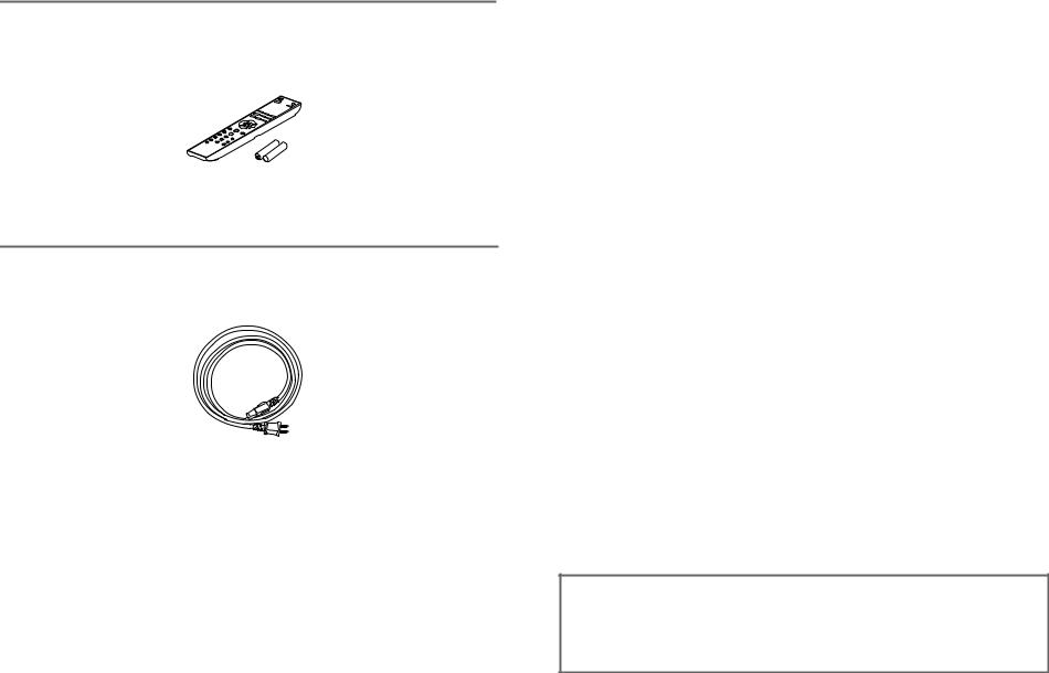
Make sure you have the following accessories:
 Remote controller and two batteries
Remote controller (RC-829S) . . . . . . . . . . . . . . . . . . . . . . . . . . . . . . . . . . . . . . . . . . . . . (1)
Batteries (R03) . . . . . . . . . . . . . . . . . . . . . . . . . . . . . . . . . . . . . . . . . . . . . . . . . . . . . . . . . (2)
 Power cord
Power cord (1.8 m) . . . . . . . . . . . . . . . . . . . . . . . . . . . . . . . . . . . . . . . . . . . . . . . . . . . . . . (1) (Plug type varies from country to country.)
*In catalogs and on packaging, the letter at the end of the product name indicates the color. Specifications and operations are the same regardless of color.
Thank you for purchasing an Onkyo Integrated Amplifier. Please read this manual thoroughly before making connections and plugging in the unit.
Following the instructions in this manual will enable you to obtain optimum performance and listening enjoyment from your new Integrated Amplifier.
Please retain this manual for future reference.
En
8
Contents |
|
Introduction |
|
Important Safety Instructions ................................................................................. |
2 |
Precautions............................................................................................................... |
3 |
Features .................................................................................................................... |
4 |
Technologies ............................................................................................................ |
5 |
Block Diagram .......................................................................................................... |
7 |
Supplied Accessories.............................................................................................. |
8 |
Before Using the Integrated Amplifier ................................................................. |
10 |
Installing the Batteries ....................................................................................... |
10 |
Using the Remote Controller ............................................................................. |
10 |
Installing the Integrated Amplifier ...................................................................... |
10 |
Getting to Know the Integrated Amplifier ............................................................ |
11 |
Front Panel ........................................................................................................ |
11 |
Rear Panel......................................................................................................... |
13 |
Remote Controller.............................................................................................. |
14 |
Connections |
|
Connections ........................................................................................................... |
15 |
Connecting Your Speakers................................................................................ |
15 |
Cable and Jacks ................................................................................................ |
17 |
Connecting the Power Cord............................................................................... |
18 |
Connecting a CD Player .................................................................................... |
19 |
Connecting an Onkyo Dock ............................................................................... |
20 |
Connecting a Tuner ........................................................................................... |
21 |
Connecting Onkyo u Components.................................................................. |
22 |
Connecting a Turntable ..................................................................................... |
23 |
Connecting a Cassette Tape Deck .................................................................... |
23 |
Connecting a Recording Component................................................................. |
24 |
Using the Integrated Amplifier as a Preamplifier ............................................... |
25 |
Separating the Pre-amp and Main Amp Units ................................................... |
26 |
Using the Integrated Amplifier as a Power Amplifier.......................................... |
27 |
Turning On & Basic Operations |
|
Basic Operations.................................................................................................... |
28 |
Turning On/Off the Integrated Amplifier............................................................. |
28 |
Selecting Speakers A and Speakers B.............................................................. |
29 |
Adjusting the Volume......................................................................................... |
29 |
Selecting the Input Source................................................................................. |
29 |
Adjusting the Display Brightness ....................................................................... |
30 |
Using the Direct Function .................................................................................. |
30 |
Adjusting the Bass, Treble and Balance............................................................ |
31 |
Muting the Sound............................................................................................... |
31 |
Changing the Display Information...................................................................... |
32 |
Using Headphones ............................................................................................ |
32 |
Controlling Other Onkyo Components ................................................................ |
33 |
Controlling the Onkyo CD Player....................................................................... |
33 |
Controlling the Onkyo Dock ............................................................................... |
33 |
Controlling the Onkyo Network Tuner................................................................ |
34 |
Using the Integrated Amplifier as a USB Audio Device ..................................... |
35 |
Connecting a PC................................................................................................ |
35 |
Installing USB drivers ........................................................................................ |
35 |
Playing Music Files from the PC........................................................................ |
35 |
Advanced Operations |
|
Custom Setup......................................................................................................... |
36 |
Changing Input Names...................................................................................... |
36 |
Skipping Unused Inputs..................................................................................... |
37 |
Setting the Headphone Level ............................................................................ |
37 |
Setting the Auto Standby Function .................................................................... |
38 |
Setting the Route............................................................................................... |
39 |
Restoring the Default Settings........................................................................... |
40 |
Others |
|
Troubleshooting..................................................................................................... |
41 |
Specifications......................................................................................................... |
43 |
En
9
Before Using the Integrated Amplifier
Installing the Batteries
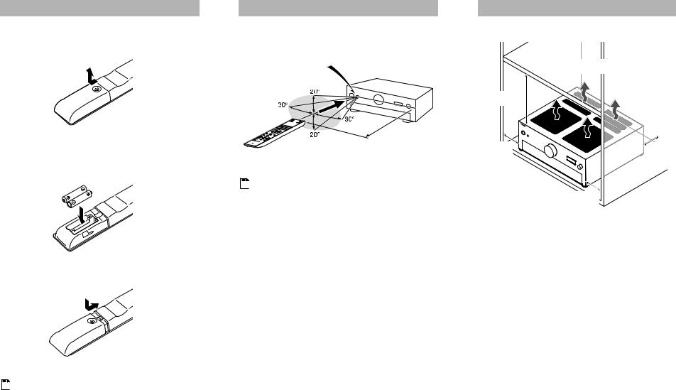
1To open the battery compartment, press the small hollow and slide the cover.
2Insert the two supplied batteries (R03) in accordance with the polarity diagram inside the battery compartment.
3 Replace the cover and slide it shut.
Using the Remote Controller
To use the remote controller, point it at the integrated amplifier’s remote control sensor, as shown below.
Remote control sensor
Integrated amplifier
Approx. 5 m
 Note
Note
•The remote controller may not work reliably if the integrated amplifier is subjected to bright light, such as direct sunlight or inverter-type fluorescent lights. Keep this in mind when installing.
•If another remote controller of the same type is used in the same room, or the integrated amplifier is installed close to equipment that uses infrared rays, the remote controller may not work reliably.
•Don’t put anything, such as a book, on the remote controller, because the buttons may be pressed inadvertently, thereby draining the batteries.
•The remote controller may not work reliably if the integrated amplifier is installed in a rack behind colored glass doors. Keep this in mind when installing.
•The remote controller will not work if there’s an obstacle between it and the integrated amplifier’s remote control sensor.
 Note
Note
• If the remote controller doesn’t work reliably, try replacing the batteries.
• Don’t mix new and old batteries or different types of batteries.
• If you intend not to use the remote controller for a long time, remove the batteries to prevent damage from leakage or corrosion.
En
• Remove expired batteries as soon as possible to prevent damage from leakage or corrosion.
Installing the Integrated Amplifier
Ensure proper ventilation.
30 cm
10 cm |
10 cm |
10 cm
Install the integrated amplifier on a sturdy rack or shelf. Position it so that its weight is evenly dispersed on its four legs. Do not install the integrated amplifier in a place with vibration or an unstable location.
The integrated amplifier is designed to have high conversion efficiency, however, its temperature will become much higher than other audio equipment. Therefore, make sure not to hamper heat dissipation by ensuring proper ventilation.
10
Getting to Know the Integrated Amplifier
Front Panel
a |
b |
c |
d e f g |
h i |
|
|
|
j |
|||||||||||
|
|
|
|
|
|
|
|
|
|
|
|
|
|
|
|
|
|
|
|
|
|
|
|
|
|
|
|
|
|
|
|
|
|
|
|
|
|
|
|
|
|
|
|
|
|
|
|
|
|
|
|
|
|
|
|
|
|
|
|
|
|
|
|
|
|
|
|
|
|
|
|
|
|
|
|
|
|
|
|
|
|
|
|
|
|
|
|
|
|
|
|
|
|
|
|
|
|
|
|
|
|
|
|
|
|
|
|
|
|
|
|
|
|
|
|
|
|
|
|
|
|
|
|
|
|
|
|
|
|
|
|
|
|
|
|
|
|
|
|
|
|
|
|
|
|
|
|
|
|
|
|
|
|
|
|
|
|
|
|
|
|
|
|
|
|
|
|
|
|
|
|
|
|
|
|
|
|
|
|
|
|
|
|
|
|
|
|
|
|
|
|
|
|
|
|
|
|
|
|
|
|
|
|
|
|
|
|
|
|
|
|
|
|
|
|
|
|
|
|
For detailed information, see the pages in parentheses.
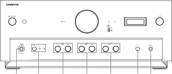
a8ON/STANDBY button ( page 28)
Sets the integrated amplifier to On or Standby.
bRemote control sensor ( page 10)
Receives control signals from the remote controller.
cMAIN IN LED ( page 27)
Lights when the integrated amplifier is used as a power amplifier (Main mode).
dVolume controller ( page 29)
Adjusts the volume.
eDIRECT switch ( page 30)
Enables or disables the Direct function.
f DIRECT LED ( page 30) |
j Front flap |
Lights when the integrated amplifier is in Direct |
Gently push on the lower end of the front panel to |
mode. |
open the flap. |
gDisplay Off LED ( page 30)
Lights when the information display is turned off.
h Information display
Displays various information.
i INPUT selector ( pages 29, 35)
Selects the input sources in sequence. It is also used to select settings.
En
11
k l
For detailed information, see the pages in parentheses.
kPOWER switch ( page 28)
This is the main power switch. When set to the OFF position (@), the integrated amplifier is completely shut down. It must be switched to the ON position (^) to set the integrated amplifier to On or Standby.
lSPEAKERS button and A/B LEDs ( page 29)
Selects Speakers A, Speakers B, or both. The A and B LEDs show which speaker set is selected.
mBASS -/+ buttons ( page 31)
Adjusts the level of bass sounds. Press the button once to display the current level value.
m |
n |
o |
p q |
nTREBLE -/+ buttons ( page 31)
Adjusts the level of treble sounds. Press the button once to display the current level value.
oBALANCE L/R buttons ( page 31)
Adjusts the balance of left and right channels.
pSETUP button ( page 36)
Selects and confirms settings.
qPHONES jack ( page 32)
Connects headphones with a standard plug.
En
12

Rear Panel
|
|
a |
|
|
|
|
|
|
|
|
b c d |
|
|
|
|
|
|
|
|
|
|
|
|
|
e f |
|
||||||||||||||||||||||||||||||||||||||||
|
|
|
|
|
|
|
|
|
|
|
|
|
|
|
|
|
|
|
|
|
|
|
|
|
|
|
|
|
|
|
|
|
|
|
|
|
|
|
|
|
|
|
|
|
|
|
|
|
|
|
|
|
|
|
|
|
|
|
|
|
|
|
|
|
|
|
|
|
|
|
|
|
|
|
|
|
|
|
|
|
|
|
|
|
|
|
|
|
|
|
|
|
|
|
|
|
|
|
|
|
|
|
|
|
|
|
|
|
|
|
|
|
|
|
|
|
|
|
|
|
|
|
|
|
|
|
|
|
|
|
|
|
|
|
|
|
|
|
|
|
|
|
|
|
|
|
|
|
|
|
|
|
|
|
|
|
|
|
|
|
|
|
|
|
|
|
|
|
|
|
|
|
|
|
|
|
|
|
|
|
|
|
|
|
|
|
|
|
|
|
|
|
|
|
|
|
|
|
|
|
|
|
|
|
|
|
|
|
|
|
|
|
|
|
|
|
|
|
|
|
|
|
|
|
|
|
|
|
|
|
|
|
|
|
|
|
|
|
|
|
|
|
|
|
|
|
|
|
|
|
|
|
|
|
|
|
|
|
|
|
|
|
|
|
|
|
|
|
|
|
|
|
|
|
|
|
|
|
|
|
|
|
|
|
|
|
|
|
|
|
|
|
|
|
|
|
|
|
|
|
|
|
|
|
|
|
|
|
|
|
|
|
|
|
|
|
|
|
|
|
|
|
|
|
|
|
|
|
|
|
|
|
|
|
|
|
|
|
|
|
|
|
|
|
|
|
|
|
|
|
|
|
|
|
|
|
|
|
|
|
|
|
|
|
|
|
|
|
|
|
|
|
|
|
|
|
|
|
|
|
|
|
|
|
|
|
|
|
|
|
|
|
|
|
|
|
|
|
|
|
|
|
|
|
|
|
|
|
|
|
|
|
|
|
|
|
|
|
|
|
|
|
|
|
|
|
|
|
|
|
|
|
|
|
|
|
|
|
|
|
|
|
|
|
|
|
|
|
|
|
|
|
|
|
|
|
|
|
|
|
|
|
|
|
|
|
|
|
|
|
|
|
|
|
|
|
|
|
|
|
|
|
|
|
|
|
|
|
|
|
|
|
|
|
|
|
|
|
|
|
|
|
|
|
|
|
|
|
|
|
|
|
|
|
|
|
|
|
|
|
|
|
|
|
|
|
|
|
|
|
|
|
|
|
|
|
|
|
|
|
|
|
|
|
|
|
|
|
|
|
|
|
|
|
|
|
|
|
|
|
|
|
|
|
|
|
|
|
|
|
|
|
|
|
|
|
|
|
|
|
|
|
|
|
|
|
|
|
|
|
|
|
|
|
|
|
|
|
|
|
|
|
|
|
|
|
|
|
|
|
|
|
|
|
|
|
|
|
|
|
|
|
|
|
|
|
|
|
|
|
|
|
|
|
|
|
|
|
|
|
|
|
|
|
|
|
|
|
|
|
|
|
|
|
|
|
|
|
|
|
|
|
|
|
|
|
|
|
|
|
|
|
|
|
|
|
|
|
|
|
|
|
|
|
|
|
|
|
|
|
|
|
|
|
|
|
|
|
|
|
|
|
|
|
|
|
|
|
|
|
|
|
|
|
|
|
|
|
|
|
|
|
|
|
|
|
|
|
|
|
|
|
|
|
|
|
|
|
|
|
|
|
|
|
|
|
|
|
|
|
|
|
|
|
|
|
|
|
|
|
|
|
|
|
|
|
|
|
|
|
|
|
|
|
|
|
|
|
|
|
|
|
|
|
|
|
|
|
|
|
|
|
|
|
|
|
|
|
|
|
|
|
|
|
|
|
|
|
|
|
|
|
|
|
|
|
|
|
|
|
|
|
|
|
|
|
|
|
|
|
|
|
|
|
|
|
|
|
|
|
|
|
|
|
|
|
|
|
|
|
|
|
|
|
|
|
|
|
|
|
|
|
|
|
|
|
|
|
|
|
|
|
|
|
|
|
|
|
|
|
|
|
|
|
|
|
|
|
|
|
|
|
|
|
|
|
|
|
|
|
|
|
|
|
|
|
|
|
|
|
|
|
|
|
|
|
|
|
|
|
|
|
|
|
|
|
|
|
|
|
|
|
|
|
|
|
|
g h i
aSPEAKERS A terminals
Connect Speakers A.
bu REMOTE CONTROL jacks
Connect Onkyo components such as Onkyo Docks, CD Players, or Network Tuner with u (Remote Interactive) jacks.
cUSB port
Connects a PC. The music files of your PC are played through the integrated amplifier.
dDIGITAL IN AES/EBU jack
Connects components such as CD players with balanced AES/EBU output.

 Note
Note
•Be careful not to connect components with analog XLR output.
eDIGITAL IN COAXIAL 1/2 jacks
Connect components such as CD players with coaxial digital audio output.
j k l m n
fDIGITAL IN OPTICAL jack
Connects components such as CD players with optical digital audio output.
gSPEAKERS B terminals
Connect Speakers B.
hPHONO (MM/MC) L/R jacks
Connect a turntable with analog audio output.
iMM/MC selector
Set this selector according to the turntable’s cartridge format ( MM/
MM/ MC).
MC).
jGND screw
Connects the turntable’s ground wire.
kLINE IN 1/2/3 L/R jacks
Connect playback devices with analog audio output.
lLINE OUT L/R jacks
Connect components such as analog line-level sources. The input signals are output with no level adjustment.
o |
mPRE OUT L/R jacks
Connect a power amplifier when the integrated amplifier is used as a preamplifier (Pre mode).
nMAIN IN L/R jacks
Connect a preamplifier when the integrated amplifier is used as a power amplifier (Main mode).
oAC INLET
Connects the supplied power cord. The other end of the power cord should be connected to a suitable wall outlet.
See “Connections” for connection information ( pages 15 to 27).
En
13
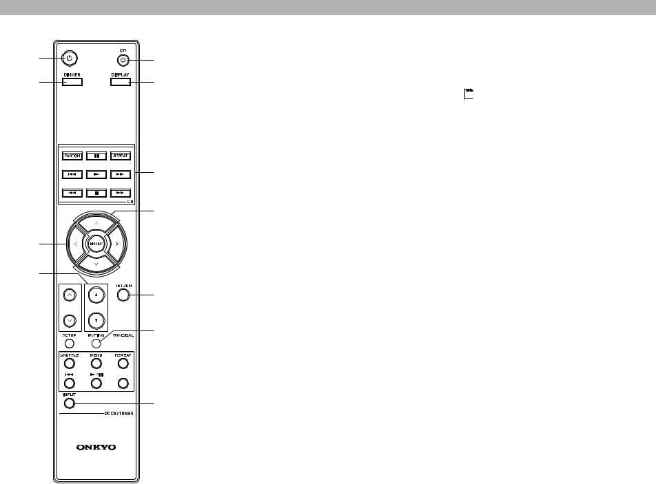
Remote Controller
|
|
For detailed information, see the pages in parentheses. |
|
aa |
d |
a 8 button ( page 28) |
|
Sets the integrated amplifier to On or Standby. |
|||
|
|||
bb |
g |
b DIMMER button ( page 30) |
|
Adjusts the display brightness. |
|||
|
|
||
|
|
c !/"/#/$ and ENTER buttons |
|
|
|
Select and adjust settings. |
|
|
|
d VOLUME q/w buttons ( page 29) |
|
|
|
Adjust the volume of the integrated amplifier. |
e |
f |
eINPUT!/" buttons ( page 29)
Select an input source.
fSETUP button ( page 36)
Enters the Setup menu.
gDISPLAY button ( page 32)
Displays the current input and settings.
h RETURN button
|
|
Returns to the previous display when changing |
cc |
|
settings. |
|
|
i MUTING button ( page 31) |
d |
|
Mutes or unmutes the integrated amplifier. |
|
j TONE/BAL button ( page 31) |
|
|
|
|
|
h |
Adjusts the tone (bass/treble) and balance of the |
|
integrated amplifier. |
|
|
|
e


i f

 j
j

 g
g
h
En
You can also use the remote controller to control your Onkyo CD Player (e.g. C-7000R), Onkyo Dock, or Onkyo Network Tuner (e.g. T-4070).
 Note
Note
•Make sure the remote controller is pointed at the CD player when using it.
•With some components, the remote controller may not work, or only partially.
•To control the Onkyo Dock and Onkyo Network Tuner, an u connection is required ( page 22).
•Refer to the manuals supplied with your Onkyo CD Players, Network Tuner or RI Docks.
Controlling the Onkyo CD player ( page 33)
d 8 CD button
e Playback mode buttons
Controlling the Onkyo Dock ( page 33)
a 8 button
b DIMMER button
f !/" and ENTER buttons
g Dock control buttons
Controlling the Onkyo Network Tuner ( page 34)
a 8 button
b DIMMER button
c !/"/#/$ and ENTER buttons
gh Tuner control buttons
14
 Loading...