


 Loading...
AV Receiver
HT-RC230
Instruction Manual
Thank you for purchasing an Onkyo AV Receiver. Please read this manual thoroughly before making connections and plugging in the unit.
Following the instructions in this manual will enable you to obtain optimum performance and listening enjoyment from your new AV Receiver.
Please retain this manual for future reference.
Contents
Introduction ................................... |
2 |
Connections................................. |
11 |
Turning On & Basic Operations ...... |
18 |
Advanced Operations ................. |
27 |
Controlling iPod & Other |
|
Components............................ |
36 |
Others........................................... |
43 |
En
WARNING:
TO REDUCE THE RISK OF FIRE OR ELECTRIC SHOCK, DO NOT EXPOSE THIS APPARATUS TO RAIN OR MOISTURE.
CAUTION:
TO REDUCE THE RISK OF ELECTRIC SHOCK, DO NOT REMOVE COVER (OR BACK). NO USER-SERVICEABLE PARTS INSIDE. REFER SERVICING TO QUALIFIED SERVICE PERSONNEL.
WARNING |
|
AVIS |
RISK OF ELECTRIC SHOCK |
|
RISQUE DE CHOC ELECTRIQUE |
DO NOT OPEN |
|
NE PAS OUVRIR |
|
|
|
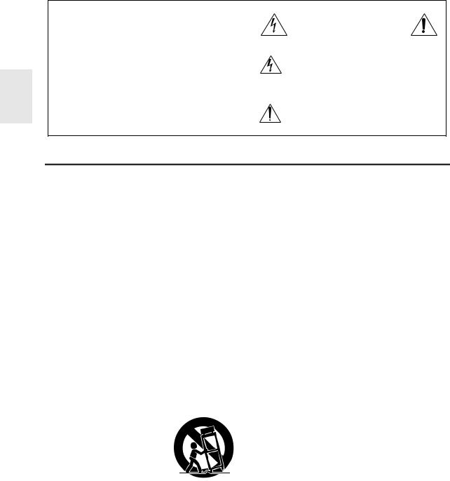
The lightning flash with arrowhead symbol, within an equilateral triangle, is intended to alert the user to the presence of uninsulated “dangerous voltage” within the product’s enclosure that may be of sufficient
magnitude to constitute a risk of electric shock to persons.
The exclamation point within an equilateral triangle is intended to alert the user to the presence of important operating and maintenance (servicing) instructions in the literature accompanying the appliance.
Important Safety Instructions
1.Read these instructions.
2.Keep these instructions.
3.Heed all warnings.
4.Follow all instructions.
5.Do not use this apparatus near water.
6.Clean only with dry cloth.
7.Do not block any ventilation openings. Install in accordance with the manufacturer’s instructions.
8.Do not install near any heat sources such as radiators, heat registers, stoves, or other apparatus (including amplifiers) that produce heat.
9.Do not defeat the safety purpose of the polarized or grounding-type plug. A polarized plug has two blades with one wider than the other. A grounding type plug has two blades and a third grounding prong. The wide blade or the third prong are provided for your safety. If the provided plug does not fit into your outlet, consult an electrician for replacement of the obsolete outlet.
10.Protect the power cord from being walked on or pinched particularly at plugs, convenience receptacles, and the point where they exit from the apparatus.
11.Only use attachments/accessories specified by the manufacturer.
12. Use only with the cart, stand, tripod, bracket, or table speci-
fied by the manufacturer, or sold with the apparatus. When
a cart is used, use caution when moving the cart/appara-
tus combination to avoid
S3125A
injury from tip-over.
13.Unplug this apparatus during lightning storms or when unused for long periods of time.
14.Refer all servicing to qualified service personnel. Servicing is required when the apparatus has been damaged in any way, such as power-supply cord or plug is damaged, liquid has been spilled or objects have fallen into the apparatus, the apparatus has been exposed to rain or moisture, does not operate normally, or has been dropped.
15.Damage Requiring Service
Unplug the apparatus from the wall outlet and refer servicing to qualified service personnel under the following conditions:
A.When the power-supply cord or plug is damaged,
B.If liquid has been spilled, or objects have fallen into the apparatus,
C.If the apparatus has been exposed to rain or water,
D.If the apparatus does not operate normally by following the operating instructions. Adjust only those controls that are covered by the operating instructions as an improper adjustment of other controls may result in damage and will often require extensive work by a qualified technician to restore the apparatus to its normal operation,
E.If the apparatus has been dropped or damaged in any way, and
F.When the apparatus exhibits a distinct change in performance this indicates a need for service.
16.Object and Liquid Entry
Never push objects of any kind into the apparatus through openings as they may touch dangerous voltage points or short-out parts that could result in a fire or electric shock.
The apparatus shall not be exposed to dripping or splashing and no objects filled with liquids, such as vases shall be placed on the apparatus.
Don’t put candles or other burning objects on top of this unit.
17.Batteries
Always consider the environmental issues and follow local regulations when disposing of batteries.
18.If you install the apparatus in a built-in installation, such as a bookcase or rack, ensure that there is adequate ventilation.
Leave 20 cm (8") of free space at the top and sides and 10 cm (4") at the rear. The rear edge of the shelf or board above the apparatus shall be set 10 cm (4") away from the rear panel or wall, creating a flue-like gap for warm air to escape.
En
2

Precautions
1.Recording Copyright—Unless it’s for personal use only, recording copyrighted material is illegal without the permission of the copyright holder.
2.AC Fuse—The AC fuse inside the unit is not user-ser- viceable. If you cannot turn on the unit, contact your Onkyo dealer.
3.Care—Occasionally you should dust the unit all over with a soft cloth. For stubborn stains, use a soft cloth dampened with a weak solution of mild detergent and water. Dry the unit immediately afterwards with a clean cloth. Don’t use abrasive cloths, thinners, alcohol, or other chemical solvents, because they may damage the finish or remove the panel lettering.
4.Power WARNING
BEFORE PLUGGING IN THE UNIT FOR THE FIRST TIME, READ THE FOLLOWING SECTION CAREFULLY.
AC outlet voltages vary from country to country. Make sure that the voltage in your area meets the voltage requirements printed on the unit’s rear panel (e.g., AC 230 V, 50 Hz or AC 120 V, 60 Hz).
The power cord plug is used to disconnect this unit from the AC power source. Make sure that the plug is readily operable (easily accessible) at all times.
Pressing ON/STANDBY to select Standby mode does not fully shutdown the unit. If you do not intend to use the unit for an extended period, remove the power cord from the AC outlet.
5.Preventing Hearing Loss Caution
Excessive sound pressure from earphones and headphones can cause hearing loss.
6.Batteries and Heat Exposure Warning
Batteries (battery pack or batteries installed) shall not be exposed to excessive heat as sunshine, fire or the like.
7.Never Touch this Unit with Wet Hands—Never handle this unit or its power cord while your hands are wet or damp. If water or any other liquid gets inside this unit, have it checked by your Onkyo dealer.
8.Handling Notes
•If you need to transport this unit, use the original packaging to pack it how it was when you originally bought it.
•Do not leave rubber or plastic items on this unit for a long time, because they may leave marks on the case.
•This unit’s top and rear panels may get warm after prolonged use. This is normal.
•If you do not use this unit for a long time, it may not work properly the next time you turn it on, so be sure to use it occasionally.
For U.S. models
FCC Information for User CAUTION:
The user changes or modifications not expressly approved by the party responsible for compliance could void the user’s authority to operate the equipment.
NOTE:
This equipment has been tested and found to comply with the limits for a Class B digital device, pursuant to Part 15 of the FCC Rules. These limits are designed to provide reasonable protection against harmful interference in a residential installation.
This equipment generates, uses and can radiate radio frequency energy and, if not installed and used in accordance with the instructions, may cause harmful interference to radio communications. However, there is no guarantee that interference will not occur in a particular installation. If this equipment does cause harmful interference to radio or television reception, which can be determined by turning the equipment off and on, the user is encouraged to try to correct the interference by one or more of the following measures:
•Reorient or relocate the receiving antenna.
•Increase the separation between the equipment and receiver.
•Connect the equipment into an outlet on a circuit different from that to which the receiver is connected.
•Consult the dealer or an experienced radio/TV technician for help.
For Canadian Models
NOTE: THIS CLASS B DIGITAL APPARATUS COMPLIES WITH CANADIAN ICES-003.
For models having a power cord with a polarized plug: CAUTION: TO PREVENT ELECTRIC SHOCK, MATCH WIDE BLADE OF PLUG TO WIDE SLOT, FULLY INSERT.
Modèle pour les Canadien
REMARQUE: CET APPAREIL NUMÉRIQUE DE LA CLASSE B EST CONFORME À LA NORME NMB003 DU CANADA.
Sur les modèles dont la fiche est polarisée: ATTENTION: POUR ÉVITER LES CHOCS ÉLECTRIQUES, INTRODUIRE LA LAME LA PLUS LARGE DE LA FICHE DANS LA BORNE CORRESPONDANTE DE LA PRISE ET POUSSER JUSQU’AU FOND.
En
3
Supplied Accessories
Make sure you have the following accessories:
Indoor FM antenna ( 16)
AM loop antenna ( 16)
Speaker cable labels ( 11)
Remote controller and two batteries (AA/R6) ( 4)
*In catalogs and on packaging, the letter at the end of the product name indicates the color. Specifications and operations are the same regardless of color.
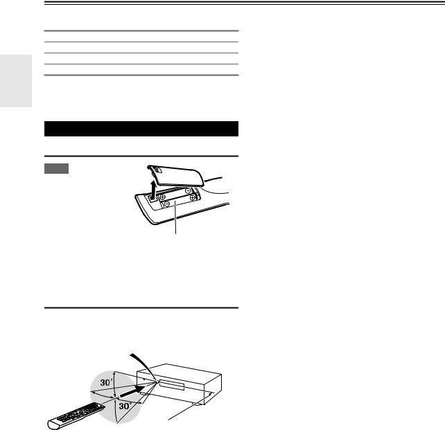
Using the Remote Controller
Installing the Batteries
Note
• If the remote controller
doesn’t work reliably, try replacing the batteries.
• Don’t mix new and old batteries or different
types of batteries.
• If you intend not to use the remote controller for
a long time, remove the batteries to prevent damage from leakage or corrosion.
•Remove expired batteries as soon as possible to prevent damage from leakage or corrosion.
Aiming the Remote Controller
To use the remote controller, point it at the AV receiver’s remote control sensor, as shown below.
Remote control sensor
AV receiver
 Approx. 16 ft. (5 m)
En
4

Contents
Introduction |
|
Important Safety Instructions ......................................... |
2 |
Precautions....................................................................... |
3 |
Supplied Accessories...................................................... |
4 |
Using the Remote Controller .......................................... |
4 |
Features ............................................................................ |
6 |
Front & Rear Panels......................................................... |
7 |
Front Panel..................................................................... |
7 |
Display............................................................................ |
8 |
Rear Panel ..................................................................... |
8 |
Remote Controller............................................................ |
9 |
Controlling the AV Receiver ........................................... |
9 |
About Home Theater...................................................... |
10 |
Speakers A and B ........................................................ |
10 |
Enjoying Home Theater................................................ |
10 |
Connections |
|
Connecting the AV Receiver ......................................... |
11 |
Connecting Your Speakers .......................................... |
11 |
About AV Connections ................................................. |
13 |
Connecting Components with HDMI ............................ |
14 |
Connecting External Components................................ |
15 |
Using the AUX INPUT jack on the front panel.............. |
15 |
Connecting Onkyo u Components ............................ |
16 |
Connecting Antenna..................................................... |
16 |
Which Connections Should I Use?............................... |
17 |
Turning On & Basic Operations |
|
Turning On/Off the AV Receiver ................................... |
18 |
Turning On ................................................................... |
18 |
Turning Off ................................................................... |
18 |
Basic Operations............................................................ |
19 |
Playing the Connected Component.............................. |
19 |
Displaying Source Information ..................................... |
19 |
Using the Music Optimizer ........................................... |
19 |
Setting the Display Brightness ..................................... |
19 |
Muting the AV Receiver................................................ |
20 |
Using the Sleep Timer.................................................. |
20 |
Using Headphones....................................................... |
20 |
Changing the Input Display .......................................... |
20 |
Selecting Speakers A and B......................................... |
20 |
Listening to the Radio ................................................... |
21 |
Using the Tuner............................................................ |
21 |
Presetting FM/AM Stations........................................... |
22 |
Recording ....................................................................... |
23 |
Using the Listening Modes ........................................... |
24 |
Selecting Listening Modes ........................................... |
24 |
About Listening Modes................................................. |
24 |
Advanced Operations |
|
Advanced Setup ............................................................. |
27 |
On-screen Setup Menus............................................... |
27 |
Common Procedures in Setup Menu ........................... |
27 |
HDMI Input ................................................................... |
28 |
Component (Component Video Input).......................... |
28 |
Digital Audio (Digital Audio Input)................................. |
28 |
Sp Config (Speaker Configuration)............................... |
29 |
Sp Distance (Speaker Distance) .................................. |
29 |
Level Cal (Level Calibration) ........................................ |
30 |
Audio Adjust ................................................................. |
30 |
Name Edit..................................................................... |
31 |
Hardware ...................................................................... |
31 |
HDMI Setup .................................................................. |
31 |
Using the Audio Settings .............................................. |
33 |
Digital Input Signal Formats ......................................... |
35 |
Adjusting the Bass & Treble ......................................... |
35 |
Controlling iPod & Other Components |
|
Controlling iPod ............................................................. |
36 |
Connecting an Onkyo Dock.......................................... |
36 |
Using the Onkyo Dock.................................................. |
37 |
Controlling Your iPod.................................................... |
38 |
Controlling Other Onkyo Components ........................ |
40 |
Preprogrammed Remote Control Codes ...................... |
40 |
Entering Remote Control Codes................................... |
40 |
Remote Control Codes for |
|
Onkyo Components Connected via u..................... |
40 |
Resetting REMOTE MODE Buttons ............................. |
41 |
Resetting the Remote Controller .................................. |
41 |
Controlling Other Components ..................................... |
41 |
Others |
|
Troubleshooting ............................................................. |
43 |
Specifications ................................................................. |
47 |
About HDMI..................................................................... |
48 |
Using an RIHD-compatible TV, Player, or Recorder ... |
49 |
To reset the AV receiver to its factory defaults, turn it on and, while holding down VCR/DVR, press
ON/STANDBY ( 43).
En
5

Features
Amplifier
•60 Watts/Channel @ 8 ohms (FTC)
•Optimum Gain Volume Circuitry
•H.C.P.S. (High Current Power Supply) Massive High Power Transformer
Processing
•HDMI (Ver.1.4 with Audio Return Channel, 3D), DeepColor, x.v.Color*, Lip Sync, DTS*1-HD Master Audio, DTS-HD High Resolution Audio, Dolby TrueHD*2, Dolby Digital Plus, DSD and Multi-CH PCM
•Non-Scaling Configuration
•A-Form Listening Mode Memory
•Direct Mode
•Music Optimizer*3 for Compressed Digital Music files
•192 kHz/24-bit D/A Converters
•Powerful and Highly Accurate 32-bit Processing DSP
Connections
•3 HDMI*4 Inputs and 1 Output
•Onkyo pfor System Control
•3 Digital Inputs (2 Optical/1 Coaxial)
•Component Video Switching (2 Inputs/1 Output)
•Front “Line in” Input for Portable audio player
•Universal Port for the Dock for iPod*/HD Radio™*5 tuner module
•Banana Plug-Compatible Speaker Posts
Miscellaneous
•40 FM/AM Presets
•Crossover Adjustment (40/50/60/80/100/120/150/200 Hz)
•A/V Sync Control Function (up to 100 ms)
•On-Screen Display via HDMI
*1
Manufactured under license under U.S. Patent #’s: 5,451,942; 5,956,674; 5,974,380; 5,978,762; 6,226,616; 6,487,535; 7,212,872; 7,333,929; 7,392,195; 7,272,567 & other U.S. and worldwide patents issued & pending. DTS is a registered trademark and the DTS logos, Symbol are trademarks of DTS, Inc.
© 1996-2008 DTS, Inc. All Rights Reserved.
*2
Manufactured under license from Dolby Laboratories. “Dolby”, “Pro Logic” and the double-D symbol are trademarks of Dolby Laboratories.
*3 Music Optimizer™ is a trademark of Onkyo Corporation.
*4
“HDMI, the HDMI Logo, and High-Definition Multimedia Interface are trademarks or registered trademarks of HDMI Licensing LLC in the United States and other countries.”
*5
HD Radio™ and the HD Radio Ready logo are proprietary trademarks of iBiquity Digital Corporation.
To receive HD Radio broadcasts, you must install an Onkyo UP-HT1 HD Radio tuner module (sold separately).
*iPod is a trademark of Apple Inc., registered in the U.S. and other countries.
*“x.v.Color” is a trademark of Sony Corporation.
En
6
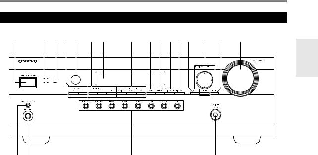
Front & Rear Panels
Front Panel
a |
b c de f g |
h |
ij klm n o |
p |
q r |
|
s |
t |
|
The actual front panel has various logos printed on it. They are not shown here for clarity.
The page numbers in parentheses show where you can find the main explanation for each item.
a ON/STANDBY button ( 18)
b STANDBY indicator ( 18)
c HDMI THRU indicator ( 32)
d SPEAKERS A and B buttons ( 10, 20)
e Remote control sensor ( 4)
f TONE LEVEL and TONE buttons ( 35)
g Display ( 8)
h LISTENING MODE buttons ( 24)
i DIMMER button ( 19)
j MEMORY button ( 22)
k TUNING MODE button ( 21) l DISPLAY button ( 19)
m SETUP button ( 27)
nTUNING, PRESET ( 21 to 22), arrow and
ENTER buttons
o RETURN button
p MASTER VOLUME control ( 19)
q MUSIC OPTIMIZER button ( 19, 34) r PHONES jack ( 20)
s Input selector buttons ( 19)
t AUX INPUT LINE IN jack ( 15)
En
7
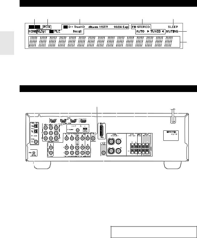
Display
a |
b |
c |
d |
e |
|
|
|
|
f |
|
|
|
|
g |
For detailed information, see the pages in parentheses. a A and B speaker indicators ( 10, 20)
b Audio input indicators
c Listening mode and format indicators ( 19, 24) d Tuning indicators ( 21)
e SLEEP indicator ( 20)
f MUTING indicator ( 20)
g Message area
Rear Panel
a |
|
|
|
|
|
|
|
|
|
|
|
|
|
|
b c |
|
|
|
|
|
|
|
|
|
|
|
|
|
|
def g h i |
|
|
|
j |
||||||||||||||||||||||||||||||||||||||||||||||||||
|
|
|
|
|
|
|
|
|
|
|
|
|
|
|
|
|
|
|
|
|
|
|
|
|
|
|
|
|
|
|
|
|
|
|
|
|
|
|
|
|
|
|
|
|
|
|
|
|
|
|
|
|
|
|
|
|
|
|
|
|
|
|
|
|
|
|
|
|
|
|
|
|
|
|
|
|
|
|
|
|
|
|
|
|
|
|
|
|
|
|
|
|
|
|
|
|
|
|
|
|
|
|
|
|
|
|
|
|
|
|
|
|
|
|
|
|
|
|
|
|
|
|
|
|
|
|
|
|
|
|
|
|
|
|
|
|
|
|
|
|
|
|
|
|
|
|
|
|
|
|
|
|
|
|
|
|
|
|
|
|
|
|
|
|
|
|
|
|
|
|
|
|
|
|
|
|
|
|
|
|
|
|
|
|
|
|
|
|
|
|
|
|
|
|
|
|
|
|
|
|
|
|
|
|
|
|
|
|
|
|
|
|
|
|
|
|
|
|
|
|
|
|
|
|
|
|
|
|
|
|
|
|
|
|
|
|
|
|
|
|
|
|
|
|
|
|
|
|
|
|
|
|
|
|
|
|
|
|
|
|
|
|
|
|
|
|
|
|
|
|
|
|
|
|
|
|
|
|
|
|
|
|
|
|
|
|
|
|
|
|
|
|
|
|
|
|
|
|
|
|
|
|
|
|
|
|
|
|
|
|
|
|
|
|
|
|
|
|
|
|
|
|
|
|
|
|
|
|
|
|
|
|
|
|
|
|
|
|
|
|
|
|
|
|
|
|
|
|
|
|
|
|
|
|
|
|
|
|
|
|
|
|
|
|
|
|
|
|
|
|
|
|
|
|
|
|
|
|
|
|
|
|
|
|
|
|
|
|
|
|
|
|
|
|
|
|
|
|
|
|
|
|
|
|
|
|
|
|
|
|
|
|
|
|
|
|
|
|
|
|
|
|
|
|
|
|
|
|
|
|
|
|
|
|
|
|
|
|
|
|
|
|
|
|
|
|
|
|
|
|
|
|
|
|
|
|
|
|
|
|
|
|
|
|
|
|
|
|
|
|
|
|
|
|
|
|
|
|
|
|
|
|
|
|
|
|
|
|
|
|
|
|
|
|
|
|
|
|
|
|
|
|
|
|
|
|
|
|
|
|
|
|
|
|
|
|
|
|
|
|
|
|
|
|
|
|
|
|
|
|
|
|
|
|
|
|
|
|
|
|
|
|
|
|
|
|
|
|
|
|
|
|
|
|
|
|
|
|
|
|
|
|
|
|
|
|
|
|
|
|
|
|
|
|
|
|
|
|
|
|
|
|
|
|
|
|
|
|
|
|
|
|
|
|
|
|
|
|
|
|
|
|
|
|
|
|
|
|
|
|
|
|
|
|
|
|
|
|
|
|
|
|
|
|
|
|
|
|
|
|
|
|
|
|
|
|
|
|
|
|
|
|
|
|
|
|
|
|
|
|
|
|
|
|
|
|
|
|
|
|
|
|
|
|
|
|
|
|
|
|
|
|
|
|
|
|
|
|
|
|
|
|
|
|
|
|
|
|
|
|
|
|
|
|
|
|
|
|
|
|
|
|
|
|
|
|
|
|
|
|
|
|
|
|
|
|
|
|
|
|
|
|
|
|
|
|
|
|
|
|
|
|
|
|
|
|
|
|
|
|
|
|
|
|
|
|
|
|
|
|
|
|
|
|
|
|
|
|
|
|
|
|
|
|
|
|
|
|
|
|
|
|
|
|
|
|
|
|
|
|
|
|
|
|
|
|
|
|
|
|
|
|
|
|
|
|
|
|
|
|
|
|
|
|
|
|
|
|
|
|
|
|
|
|
|
|
|
|
|
|
|
|
|
|
|
|
|
|
|
|
|
|
|
|
|
|
|
|
|
|
|
|
|
|
|
|
|
|
|
|
|
|
|
|
|
|
|
|
|
|
|
|
|
|
|
|
|
|
|
|
|
|
|
|
|
|
|
|
|
|
|
|
|
|
|
|
|
|
|
|
|
|
|
|
|
|
|
|
|
|
|
|
|
|
|
|
|
|
|
|
|
|
|
|
|
|
|
|
|
|
|
|
|
|
|
|
|
|
|
|
|
|
|
|
|
|
|
|
|
|
|
|
|
|
|
|
|
|
|
|
|
|
|
|
|
|
|
|
|
|
|
|
|
|
|
|
|
|
|
|
|
|
|
|
|
|
|
|
|
|
|
|
|
|
|
|
|
|
|
|
|
|
|
|
|
|
|
|
|
|
|
|
|
|
|
|
|
|
|
|
|
|
|
|
|
|
|
|
|
|
|
|
|
|
|
|
|
|
|
|
|
|
|
|
|
|
|
|
|
|
|
|
|
|
|
|
|
|
|
|
|
|
|
|
|
|
|
|
|
|
|
|
|
|
|
|
|
|
|
|
|
|
|
|
|
|
|
|
|
|
|
|
|
|
|
|
|
|
|
|
|
|
|
|
|
|
|
|
|
|
|
|
|
|
|
|
|
|
|
|
|
|
|
|
|
|
|
|
|
|
|
|
|
|
|
|
|
|
|
|
|
|
|
|
|
|
|
|
|
|
|
|
|
|
|
|
|
|
|
|
|
|
|
|
|
|
|
|
|
|
|
|
|
|
|
|
|
|
|
|
|
|
|
|
|
|
|
|
|
|
|
|
|
|
|
|
|
|
|
|
|
|
|
|
|
|
|
|
|
|
|
|
|
|
|
|
|
|
|
|
|
|
|
|
|
|
|
|
|
|
|
|
|
|
|
|
|
|
|
|
|
|
|
|
|
|
|
|
|
|
|
|
|
|
|
|
|
|
|
|
|
|
|
|
|
|
|
|
|
|
|
|
|
|
|
|
|
|
|
|
|
|
|
|
|
|
|
|
|
|
|
|
|
|
|
|
|
|
|
|
|
|
|
|
|
|
|
|
|
|
|
|
|
|
|
|
|
|
|
|
|
|
|
|
|
|
|
|
|
|
|
|
|
|
|
|
|
|
|
|
|
|
|
|
|
|
|
|
|
|
|
|
|
|
|
|
|
|
|
|
|
|
|
|
|
|
|
|
|
|
|
|
|
|
|
|
|
|
|
|
|
|
|
|
|
|
|
|
|
|
|
|
|
|
|
|
|
|
|
|
|
|
|
|
|
|
|
|
|
|
|
|
|
|
|
|
|
|
|
|
|
|
|
|
|
|
|
|
|
|
|
|
|
|
|
|
|
|
|
|
|
|
|
|
|
|
|
|
|
|
|
|
|
|
|
|
|
|
|
|
|
|
|
|
|
|
|
|
|
|
|
|
|
|
|
|
|
|
|
|
|
|
|
|
|
|
|
|
|
|
|
|
|
|
|
|
|
|
|
|
|
|
|
|
|
|
|
|
|
|
|
|
|
|
|
|
|
|
|
|
|
|
|
|
|
|
|
|
|
|
|
|
|
|
|
|
|
|
|
|
|
|
|
|
|
|
|
|
|
|
|
|
|
|
|
|
|
|
|
|
|
|
|
|
|
|
|
|
|
|
|
|
|
|
|
|
|
|
|
|
|
|
|
|
|
|
|
|
|
|
|
|
|
|
|
|
|
|
|
|
|
|
|
|
|
|
|
|
|
|
|
|
|
|
|
|
|
|
|
|
|
|
|
|
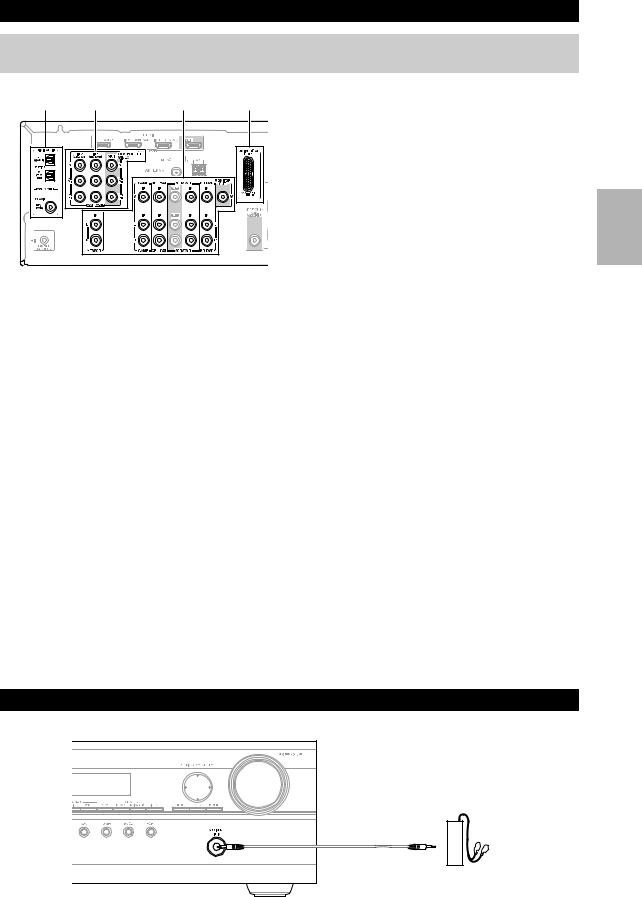
k |
l |
m |
a DIGITAL IN COAXIAL and OPTICAL jacks b COMPONENT VIDEO IN and OUT jacks c HDMI IN and OUT jacks
d FM ANTENNA jack and AM ANTENNA terminal e MONITOR OUT V jack
f UNIVERSAL PORT jack
g FRONT SPEAKERS A terminals
hSPEAKERS terminals (SURR, CENTER)
i FRONT SPEAKERS B terminals j Power cord
k uREMOTE CONTROL jack
lComposite video and analog audio jacks (BD/DVD IN, VCR/DVR IN and OUT, CBL/SAT IN, GAME IN, TV/CD IN)
m SUBWOOFER PRE OUT jack
See “Connecting the AV Receiver” for connection information ( 11 to 17).
En
8
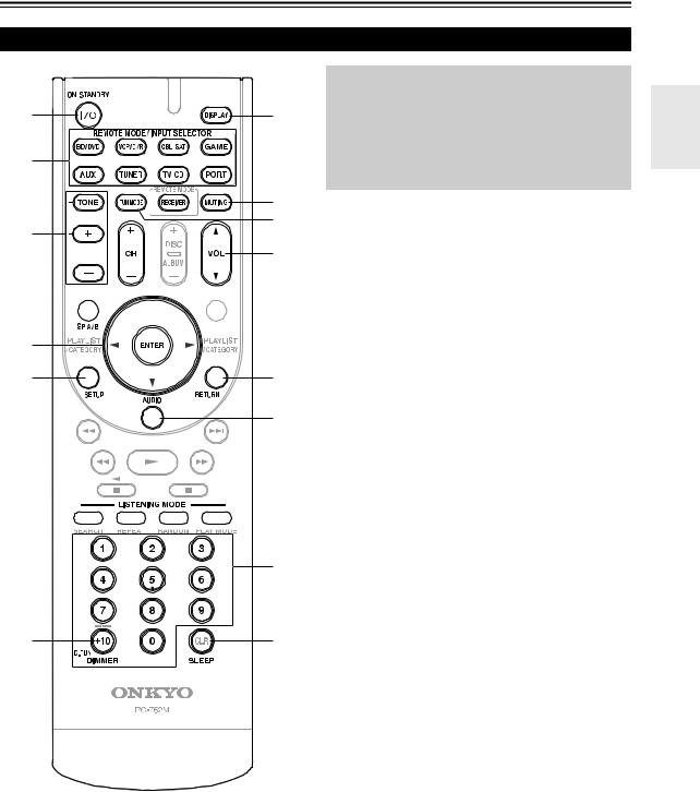
Remote Controller
Controlling the AV Receiver
a |
i |
|
c |
||
|
||
b |
|
|
|
j |
|
c |
d |
|
|
||
|
k |


 e d
e d


e a
f |
l |
m
g


|
f |
|
h |
n |
|
b |
||
|
To control the AV receiver, press RECEIVER to select Receiver mode.
You can also use the remote controller to control Onkyo Blu-ray Disc/DVD player, CD player, and other components.
See “Entering Remote Control Codes” for more details ( 40).
For detailed information, see the pages in parentheses. a ON/STANDBY button ( 18)
bREMOTE MODE/INPUT SELECTOR buttons ( 19)
c TONE, + and – buttons ( 35) d SP A/B button ( 10, 20)
e Arrow q/w/e/rand ENTER buttons f SETUP button ( 27)
g LISTENING MODE buttons ( 24) h DIMMER button ( 19)
i DISPLAY button ( 19) j MUTING button ( 20) k VOL q/wbutton ( 19) l RETURN button
m AUDIO button ( 33) n SLEEP button ( 20)
Controlling the tuner
To control the AV receiver’s tuner, press TUNER (or
RECEIVER).
You can select AM or FM by pressing TUNER repeatedly.
a Arrow q/wbuttons ( 21)
b D.TUN button ( 21)
c DISPLAY button
d TUN MODE button ( 21)
e CH +/– button ( 22)
f Number buttons ( 21)
En
9
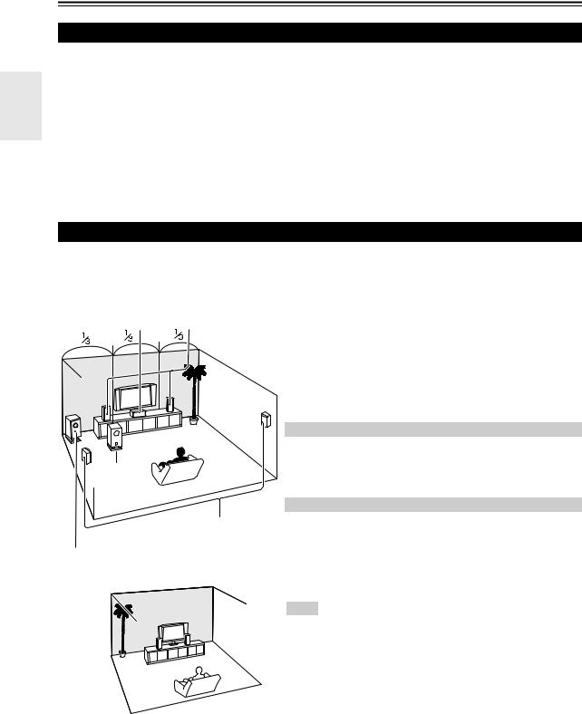
About Home Theater
Speakers A and B
You can use two sets of speakers with the AV receiver: Speakers A and Speakers B.
Speakers A should be used in your main listening room for up to 5.1-channel playback.
*While Speakers B is on, Speakers A is reduced to 2.1-channel playback.
Speakers B can be used in another room and offers 2-channel stereo playback.
Speakers A |
Speakers B |
Indicator |
Output |
|||||
|
|
|
|
|
|
|
|
|
On |
On |
|
A |
|
|
B |
|
Speakers A: 2.1 channels |
|
|
|
|
|
|
Speakers B: 2 channels |
||
|
|
|
|
|
|
|
|
|
|
|
|
|
|
|
|
|
|
|
Off |
|
|
|
|
|
|
Speakers A: 5.1 channels |
|
|
A |
|
|
|
|
||
|
|
|
|
|
|
|
|
|
|
|
|
|
|
|
|
|
|
Off |
On |
|
|
|
|
|
|
Speakers B: 2 channels |
|
|
|
|
B |
|
|||
|
|
|
|
|
|
|
|
|
|
|
|
|
|
|
|
|
|
|
Off |
|
|
|
|
|
|
No sound |
|
|
|
|
|
|
|
|
|
Enjoying Home Theater
Thanks to the AV receiver’s superb capabilities, you can enjoy surround sound with a real sense of movement in your own home—just like being in a movie theater or concert hall. With Blu-ray Discs, you can enjoy DTS and Dolby Digital. With analog or digital TV, you can enjoy Dolby Pro Logic II, DTS Neo:6, or Onkyo’s original DSP listening modes.
Speakers A: Main Room
ba
Corner position
1/3 of wall position
c
d
Speakers B: Sub Room
aFront speakers
These output the overall sound. Their role in a home theater is to provide a solid anchor for the sound image. They should be positioned facing the listener at about ear level, and equidistant from the TV. Angle them inward so as to create a triangle, with the listener at the apex.
bCenter speaker
This speaker enhances the front speakers, making sound movements distinct and providing a full sound image. In movies it’s used mainly for dialog. Position it close to your TV facing forward at about ear level, or at the same height as the front speakers.
*While Speakers B is on, this speaker outputs no sound. c Surround speakers
These speakers are used for precise sound positioning and to add realistic ambience. Position them at the sides of the listener, or slightly behind, about 2 to 3 feet (60 to 100 cm) above ear level. Ideally they should be equidistant from the listener.
*While Speakers B is on, these speakers outputs no sound.
dSubwoofer
The subwoofer handles the bass sounds of the LFE (Low-Frequency Effects) channel. The volume and quality of the bass output from your subwoofer will depend on its position, the shape of your listening room, and your listening position. In general, a good bass sound can be obtained by installing the subwoofer in a front corner, or at one-third the width of the wall, as shown.
Tip
•To find the best position for your subwoofer, while playing a movie or some music with good bass, experiment by placing your subwoofer at various positions within the room, and choose the one that provides the most satisfying results.
En
10
Connecting the AV Receiver
Connecting Your Speakers
Speaker Configuration
The following table indicates the channels you should use depending on the number of speakers that you have.
For 5.1-channel surround-sound playback, you need five speakers and a powered subwoofer.
Number of channels |
2 |
3 |
4 |
5 |
|
|
|
|
|
Front speakers |
|
|
|
|
|
|
|
|
|
Center speaker |
|
|
|
|
|
|
|
|
|
Surround speakers |
|
|
|
|
|
|
|
|
|
No matter how many speakers you use, a powered subwoofer is recommended for a really powerful and solid bass.
To get the best from your surround sound system, you need to set the speaker settings. You can do this manually ( 29).
Attaching the Speaker Cable Labels
The AV receiver’s positive (+) speaker terminals are colorcoded for ease of identification. (The negative (–) speaker terminals are all black.)
Speaker |
Color |
Front left |
White |
|
|
Front right |
Red |
|
|
Center |
Green |
|
|
Surround left |
Blue |
|
|
Surround right |
Gray |
|
|
The supplied speaker cable labels are also color-coded and you should attach them to the positive (+) side of each speaker cable in accordance with the table above. Then all you need to do is to match the color of each label to the corresponding speaker terminal.
•Unnecessarily long, or very thin speaker cables may affect the sound quality and should be avoided.
•Be careful not to short the positive and negative wires. Doing so may damage the AV receiver.
•Make sure the metal core of the wire does not have contact with the AV receiver’s rear panel. Doing so may damage the AV receiver.
•Don’t connect more than one cable to each speaker terminal. Doing so may damage the AV receiver.
•Don’t connect one speaker to several terminals.
Speaker Connection Precautions
Read the following before connecting your speakers:
•You can connect speakers with an impedance of between 6 and 16 ohms. If you use speakers with a lower impedance, and use the amplifier at high volume levels for a long period of time, the built-in amp protection circuit may be activated.
•Disconnect the power cord from the wall outlet before making any connections.
•Read the instructions supplied with your speakers.
•Pay close attention to speaker wiring polarity. In other words, connect positive (+) terminals only to positive (+) terminals, and negative (–) terminals only to negative (–) terminals. If you get them the wrong way around, the sound will be out of phase and will sound unnatural.
En
11

Connecting the Speaker Cables
Screw-type speaker terminals
Strip 1/2" to 5/8" (12 to 15 mm) of insu- 1/2" to 5/8"(12 to 15 mm) lation from the ends of the speaker 

cables, and twist the bare wires tightly, as shown.
Using Banana Plugs
•If you are using banana plugs, tighten the speaker terminal before inserting the banana plug.
•Do not insert the speaker code directly into the center hole of the speaker terminal.
Push-type speaker terminals
Strip 3/8" to 1/2" (10 to 12 mm) of insulation from the ends of the 3/8" to 1/2"(10 to 12 mm) speaker cables, and twist the bare wires tightly, as shown. 

The following illustration shows which speaker should be connected to each pair of terminals.
|
Surround right |
Surround left |
|
speaker |
speaker |
Front right |
Front left |
Center |
speaker A |
speaker A |
speaker |
|
Speakers A |
|
Connecting a Powered Subwoofer
|
|
|
|
|
|
|
|
|
|
|
|
|
|
|
|
|
|
|
|
|
|
|
|
|
|
|
|
|
|
|
|
|
|
|
|
|
|
|
|
|
|
|
|
|
|
|
|
|
|
|
|
|
|
|
|
|
|
|
|
|
|
|
|
|
|
|
|
|
|
|
|
|
|
|
|
|
|
|
|
|
|
|
|
|
|
|
|
|
|
|
|
|
|
|
|
|
|
|
|
|
|
|
|
|
|
|
|
|
|
|
|
|
|
|
|
|
|
|
|
|
|
|
|
|
|
|
|
|
|
|
|
|
|
|
|
|
|
|
|
|
|
|
|
|
|
|
|
|
|
|
|
|
|
|
|
|
|
|
|
|
|
|
|
|
|
|
|
|
|
|
|
|
|
|
|
|
|
|
|
|
|
|
|
|
|
|
|
|
|
|
|
|
|
|
|
|
|
|
|
|
|
|
|
|
|
|
|
|
|
|
|
|
|
|
|
|
|
|
|
|
|
|
|
|
|
|
|
|
|
|
|
|
|
|
|
|
|
|
|
|
|
|
|
|
|
|
|
|
|
|
|
|
|
|
|
|
|
|
|
|
|
|
|
|
|
|
|
|
|
|
|
|
|
|
|
|
|
|
|
|
|
|
|
|
|
|
|
|
|
|
|
|
|
|
|
|
|
|
|
|
|
|
|
|
|
|
|
|
|
|
|
|
|
|
|
|
|
|
|
|
|
|
|
|
|
|
|
|
|
|
|
|
|
|
|
|
|
|
|
|
|
|
|
|
|
|
|
|
|
|
|
|
|
|
|
|
|
|
|
|
|
|
|
|
|
|
|
|
|
|
|
|
|
|
|
|
|
|
|
|
|
|
|
|
|
|
|
|
|
|
|
|
|
|
|
|
|
|
|
|
|
|
|
|
|
|
|
|
|
|
|
|
|
|
|
|
|
|
|
|
|
|
|
|
|
|
|
|
|
|
|
|
|
|
|
|
|
|
|
|
|
|
|
|
|
|
|
|
|
|
|
|
|
|
|
|
|
|
|
|
|
|
|
|
|
|
|
|
|
|
|
|
|
|
|
|
|
|
|
|
|
|
|
|
|
|
|
|
|
|
|
|
|
|
|
|
|
|
|
|
|
|
|
|
|
|
|
|
|
|
|
|
|
|
|
|
|
|
|
|
|
|
|
|
Front right |
|
|
|
|
|
|
Front left |
|
||||||||||||||||
speaker B |
|
|
|
|
|
|
speaker B |
|
||||||||||||||||
Speakers B
Using a suitable cable, connect the AV receiver’s SUBWOOFER PRE OUT jack to an input on your powered subwoofer, as shown. If your subwoofer is unpowered and you’re using an external amplifier, connect the SUBWOOFER PRE OUT jack to an input on the amp.
En |
Powered subwoofer |
LINE INPUT
LINE INPUT
12
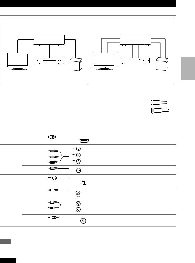
About AV Connections
Connected image with AV components
HDMI cable |
|
: Video & Audio |
|
AV receiver |
|
Blu-ray Disc/ |
|
TV, projector, etc. |
DVD player |
Game console |
Other cables |
|
: Video |
|
||
|
|
: Audio |
|
|
AV receiver |
|
|
|
|
|
|
|
|
|
|
|
|
|
|
|
|
|
|
|
|
|
|
|
|
|
Blu-ray Disc/ |
|
|
|
|||||||
|
|
|
|
||||||||
TV, projector, etc. |
Game console |
||||||||||
DVD player |
|||||||||||
•Before making any AV connections, read the manuals supplied with your AV components.
•Don’t connect the power cord until you’ve completed and double-checked all AV connections.
• Push plugs in all the way to make good connections (loose connections can cause noise or malfunc- |
|
|
|
|
|
|
Right! |
|||||||||||||||||
tions). |
|
|
|
|
|
|
|
|
|
|
|
|
|
|
|
|
|
|
|
|
|
|
|
|
• To prevent interference, keep audio and video cables away from power cords and speaker cables. |
|
|
|
|
|
|
|
|
|
|
|
|
|
|
|
|
|
|
|
|||||
|
|
|
|
|
|
|
|
|
|
|
|
|
|
|
|
|
|
|
|
|
|
|
|
|
AV Cables and Jacks |
|
|
|
|
|
|
|
|
|
|
Wrong! |
|||||||||||||
|
|
|
|
|
|
|
|
|
|
|||||||||||||||
|
|
|
|
|
|
|
|
|
|
|||||||||||||||
|
|
|
|
|
|
|
|
|
|
|
|
|
|
|
|
|
|
|
|
|
|
|
||
|
|
|
|
|
|
|
|
|
|
|
|
|
|
|
|
|
|
|
|
|
|
|
|
|
|
|
|
|
|
|
|
|
|
|
|
|
|
|
|
|
|
|
|
|
|
|
|
|
|
Signal |
Cable |
|
Jack |
|
Description |
|
|
|
|
|
|
|
|
|
|
|
|
|
|
|
|
|
|
|
Video and |
HDMI |
|
|
HDMI |
HDMI connections can carry digital video and audio. The |
|||||||||||||||||||
Audio |
|
|
|
AV receiver is compliant with HDMI. |
|
|
|
|
|
|
|
|
|
|
|
|
|
|
|
|
|
|
|
|
|
|
|
|
|
|
|
|
|
|
|
|
|
|
|
|
|
|
|
|
|
|
|
||
Video |
Component video |
Y |
Green |
|
|
||
|
|
PB/CB |
Blue |
|
|
PR/CR |
Red |
Component video separates the luminance (Y) and color difference signals (PB/CB, PR/CR), providing the best picture quality (some TV manufacturers label their component video sockets slightly differently).
Composite video |
Yellow |
Composite video is commonly used on TVs, VCRs, and |
V |
other video equipment. |
|
|
|
Audio |
Optical digital |
|
audio |
OPTICAL |
Optical digital connections allow you to enjoy digital |
||
|
|
|
sound such as PCM*, Dolby Digital or DTS. The audio |
|
|
|
|
|
|
|
quality is the same as coaxial. |
|
|
|
|
Coaxial digital |
Orange |
Coaxial digital connections allow you to enjoy digital |
audio |
sound such as PCM*, Dolby Digital or DTS. The audio |
|
|
|
quality is the same as optical. |
Analog audio (RCA)
L
R
White |
Analog audio connections (RCA) carry analog audio. |
|
|
Red |
|
1/8" (3.5 mm) |
This cable carries analog audio. |
Stereo mini plug |
|
*Available sampling rate for PCM input signal is 32/44.1/48/88.2/96 kHz. Even 176.4/192 kHz is effective in case of the HDMI connection.
Note
•The AV receiver does not support SCART plugs.
•The AV receiver’s optical digital jacks have shutter-type covers that open when an optical plug is inserted and close when it’s removed. Push plugs in all the way.
Caution
•To prevent shutter damage, hold the optical plug straight when inserting and removing.
En
13
Connecting Components with HDMI
Game console |
TV, projector, etc. |
|
Satellite, cable, set-top box, etc. Blu-ray Disc/DVD player
Connect your components to the appropriate jacks. The default input assignments are shown below.: Assignment can be changed ( 28).
Jack |
|
Signal |
Components |
Assignable |
Input |
HDMI IN1 |
Audio/Video |
Blu-ray Disc/DVD player |
|
|
HDMI IN2 |
|
Satellite, cable, set-top box, etc. |
|
|
HDMI IN3 |
|
Game console |
|
Output |
HDMI OUT |
|
TV, projector, etc. |
|
Refer to “About HDMI” ( 48) and “Using an p-compatible TV, Player, or Recorder” ( 49).
Tip
To listen to audio received by the HDMI IN jacks through your TV’s speakers:
•Set the “TV Control” setting to “On” ( 32) for an p-compatible TV.
•Set the “Audio TV OUT” setting to “On” ( 31) when the TV is not compatible with por the “TV Control” setting to “Off”.
•Set your Blu-ray Disc/DVD player’s HDMI audio output setting to PCM.
•To listen to TV audio through the AV receiver, see “Connecting External Components” ( 15).
Note
•When listening to an HDMI component through the AV receiver, set the HDMI component so that its video can be seen on the TV screen (on the TV, select the input of the HDMI component connected to the AV receiver). If the TV power is off or the TV is set to another input source, this may result in no sound from the AV receiver or the sound may be cut off.
•When the “Audio TV OUT” setting is set to “On” ( 31) to hear from your TV’s speakers, by controlling the AV receiver’s volume, the sound will be output from the AV receiver’s speakers, too. When the “TV Control” setting is set to “On” ( 32) to hear from speakers of p-compatible TV, by controlling the AV receiver’s volume, the AV receiver’s speakers will produce sound while the TV’s speakers are muted. To stop the AV receiver’s speakers producing sound, change the settings, change your TV’s settings, or turn down the AV receiver’s volume.
Audio return channel (ARC) function
Audio return channel (ARC) function enables an HDMI capable TV to send the audio stream to the HDMI OUT of the AV receiver. To use this function, you must select the TV/CD input selector.
•To use ARC function, you must select the TV/CD input selector, your TV must support ARC function and “HDMI Control (RIHD)” is set to “On” ( 32).
En
14
Connecting External Components
The on-screen setup menus appear only on a TV that is connected to the HDMI OUT. If your TV is connected to the MONITOR OUT V or the COMPONENT VIDEO OUT, use the AV receiver’s display when changing settings.
|
|
|
|
Connect your components to the appropriate jacks. The |
B |
A |
C |
D |
default input assignments are shown below. |
|
|
|
|
: Assignment can be changed ( 28). |
|
|
|
|
How to record the video |
|
|
|
|
With the connections described here, you cannot record |
|
|
|
|
the video through the AV receiver. To make a connection |
|
|
|
|
for video recording ( 23). |
No. |
Jack |
|
|
Signal |
Components |
Assignable |
|
|
|
|
|
|
|
A |
COMPONENT |
IN 1 (BD/DVD) |
|
Component |
Blu-ray Disc/DVD player |
|
|
VIDEO |
|
|
video |
|
|
|
IN 2 (CBL/SAT) |
|
Satellite, cable, set-top box, etc. |
|
||
|
|
|
|
|||
|
|
|
|
|
|
|
|
|
OUT |
|
|
TV, projector, etc. |
|
|
|
|
|
|
|
|
B |
DIGITAL IN |
OPTICAL |
IN 1 (GAME) |
Digital audio |
Game console |
|
|
|
|
|
|
|
|
|
|
|
IN 2 (TV/CD) |
|
TV, CD player |
|
|
|
|
|
|
|
|
|
|
COAXIAL (BD/DVD) |
|
Blu-ray Disc/DVD player |
|
|
|
|
|
|
|
|
|
C |
MONITOR OUT |
|
|
Composite |
TV, projector, etc. |
|
|
|
|
|
video |
|
|
|
|
|
|
|
|
|
|
BD/DVD IN |
|
|
Analog audio |
Blu-ray Disc/DVD player |
|
|
|
|
|
and composite |
|
|
|
VCR/DVR IN |
|
|
VCR or DVD recorder/Digital |
|
|
|
|
|
|
video |
Video Recorder |
|
|
|
|
|
|
|
|
|
|
|
|
|
|
|
|
CBL/SAT IN |
|
|
|
Satellite, cable, set-top box, etc. |
|
|
|
|
|
|
|
|
|
GAME IN |
|
|
|
Game console |
|
|
|
|
|
|
|
|
|
TV/CD IN |
|
|
Analog audio |
TV, CD player, Turntable*1, Cas- |
|
|
|
|
|
|
sette tape deck, MD, CD-R |
|
|
|
|
|
|
|
|
D |
UNIVERSAL PORT |
|
Analog audio/ |
Universal port optional dock |
|
|
|
|
|
|
Video |
(UP-A1 etc.) |
|
*1 Connect a turntable (MM) that has a phono preamp built-in. If your turntable (MM) doesn’t have it, you’ll need a commercially available phono preamp.
If your turntable has a moving coil (MC) type cartridge, you’ll need a commercially available MC head amp or MC transformer as well as a phono preamp. See your turntable’s manual for details.
•With connection B, you can enjoy Dolby Digital and DTS.
•If your Blu-ray Disc/DVD player has both the main stereo and multichannel outputs, be sure to connect the main stereo output using connection C.
Using the AUX INPUT jack on the front panel
Portable audio player
Analog audio line output ( 13)
En
15
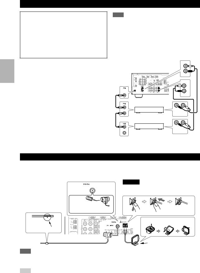
Connecting Onkyo u Components
Step 1:
Make sure that each Onkyo component is connected with an analog audio cable (connection C in the hookup examples) ( 15).
Step 2:
Make the uconnection (see illustration below).
Step 3:
If you’re using an RI Dock, or cassette tape deck, change the Input Display ( 20).
With u(Remote Interactive), you can use the following special functions:
System On/Auto Power On
When you start playback on a component connected via u, if the AV receiver is on Standby, it will automatically turn on and select that component as the input source.
Direct Change
When playback is started on a component connected via u, the AV receiver automatically selects that component as the input source.
Remote Control
You can use the AV receiver’s remote controller to control your other u-capable Onkyo components, pointing the remote controller at the AV receiver’s remote control sensor instead of the component. You must enter the appropriate remote control code first ( 40).
Note
•Use only ucables for uconnections. ucables are supplied with Onkyo players (DVD, CD, etc.).
•Some components have two ujacks. You can connect either one to the AV receiver. The other jack is for connecting additional u-capable components.
•Connect only Onkyo components to ujacks. Connecting other manufacturer’s components may cause a malfunction.
•Some components may not support all ufunctions. Refer to the manuals supplied with your other Onkyo components.
IN
L
R
|
|
TV/CD |
|
|
IN |
|
|
L |
REMOTE |
|
R |
CONTROL |
|
|
|
|
|
|
|
BD/DVD |
|
R |
L |
e.g., CD player |
ANALOG |
|
AUDIO OUT |
||
|
|
|
|
R |
L |
e.g., DVD player |
ANALOG |
|
AUDIO OUT |
||
Connecting Antenna
This section explains how to connect the supplied indoor FM antenna and AM loop antenna.
The AV receiver won’t pick up any radio signals without any antenna connected, so you must connect the antenna to use the tuner.
Caution
• Be careful that you don’t injure yourself when using thumbtacks.
En
16
Insert the plug fully into the jack.
Push. |
Insert wire. |
Release. |
Assembling the AM loop antenna
Thumbtacks, etc.
Indoor FM antenna (supplied) 

AM loop antenna (supplied)
Note
•Once your AV receiver is ready for use, you’ll need to tune into a radio station and position the antenna to achieve the best possible reception.
•Keep the AM loop antenna as far away as possible from your AV receiver, TV, speaker cables, and power cords.
Tip
•If you cannot achieve good reception with the supplied indoor FM antenna, try a commercially available outdoor FM antenna instead.
•If you cannot achieve good reception with the supplied indoor AM loop antenna, try using it with a commercially available outdoor AM antenna.
Loading...