

Omron MYK DATASHEET
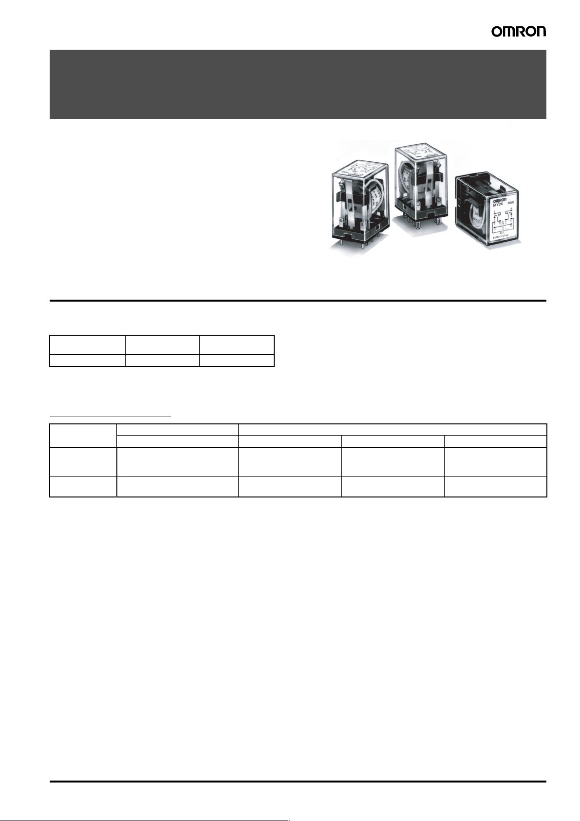
General-purpose Latching Relay
MYK
Magnetic Latching Relay Ideal for Memory
and Data Transmission Circuits
• Double-winding latch system that holds residual magnetism.
• Changes due to aging are negligible because of use of special
magnetic materials, thus ensuring long continuous holding time.
• Little change in characteristics such as contact follow, contact
pressure, etc., throughout its long life.
• Excellent vibration/shock resistance.
• Easy monitoring of ON/OFF operation thanks to the built-in operation indicator mechanism.
• Same outline dimensions as the MY Miniature Power Relay.
Ordering Information
■ List of Models
Contact form Plug-in/solder
DPDT MY2K MY2K-02
terminal model
PCB terminal
model
■ Accessories (Order Separately)
Connecting Sockets
Front-connecting Socket Back-connecting Socket
Screw terminals Solder terminals Wire-wrap terminals PCB terminals
Without Relay
Hold-down Clip
With Hold-down
Clip
Note: Refer to the MY Datasheet for detail information on the Relay Hold-down Clips and Relay-mounting Sockets.
PYF14A-E
PYF14A
PYF14-N
--- PY14-Y1 PY14QN-Y1 ---
PY14 PY14QN PY14-02
General-purpose Latching Relay MYK 1
Specifications
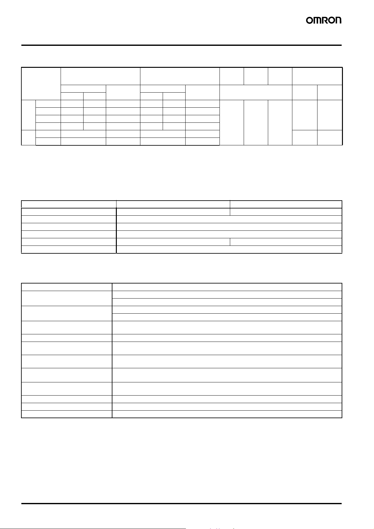
■ Coil Ratings
Rated voltage Set coil Reset coil Must-set
Rated current Resistance Rated current Resistance % of rated voltage Set coil Reset
50 Hz 60 Hz 50 Hz 60 Hz
AC 12 V 57 mA 56 mA 72 Ω 39 mA 38.2 mA 130 Ω 80%
24 V 27.5 mA 26.4 mA 320 Ω 18.6 mA 18.1 mA 550 Ω
50 V 14.0 mA 13.4 mA 1,400 Ω 3.5 mA 3.4 mA 3,000 Ω
100 V 7.1 mA 6.9 mA 5,400 Ω 3.5 mA 3.4 mA 3,000 Ω
DC 12 V 110 mA 110 Ω 50 mA 235 Ω 1.3 W 0.6 W
24 V 52 mA 470 Ω 25 mA 940 Ω
Note: 1. For AC models, the rated current values are half-wave rectified current values measured with a DC ammeter.
2. The rated current and coil resistance are measured at a coil temperature of 23°C with tolerances of +15%/–20% for AC rated current and
±15% for DC rated current, and +15% for DC coil resistance.
3. The AC coil resistance values are for reference only.
4. Performance characteristic data are measured at a coil temperature of 5°C to 35°C.
voltage
max.
Must-
reset
voltage
80%
max.
Max.
voltage
110% 0.6 to 0.9
Power
consumption
(Approx.)
(60 Hz)
0.2 to 0.5
(60 Hz)
■ Contact Ratings
Item Resistive load (cosφ = 1) Inductive load (cosφ = 0.4) (L/R = 7 ms)
Rated load 3 A at 220 VAC, 3 A at 24 VDC 0.8 A at 220 VAC, 1.5 A at 24 VDC
Rated carry current 3 A
Max. switching voltage 250 VAC, 125 VDC
Max. switching current 3 A
Max. switching power 660 VA, 72 W 176 VA, 36 W
Failure rate* (reference value) 1 mA at 1 VDC
*Note: P level: λ60 = 0.1 x 10⁻⁶/operation
coil
■ Characteristics
Contact resistance 50 mΩ max.
Set time Time: AC: 30 ms max.; DC: 15 ms max.
Min. pulse width: AC: 60 ms.; DC: 15 ms.
Reset time Time: AC: 30 ms max.; DC: 15 ms max.
Min. pulse width: AC: 60 ms.; DC: 15 ms.
Max. operating frequency Mechanical: 18,000 operations/hr
Insulation resistance 100 MΩ min. (at 500 VDC)
Dielectric strength 1,500 VAC, 50/60 Hz for 1 min (1,000 VAC between contacts of same polarity and between set and reset
Vibration resistance Destruction: 10 to 55 to 10 Hz, 0.5 mm single amplitude (1.0 mm double amplitude)
Shock resistance
Endurance Mechanical: 100,000,000 operations min. (at 18,000 operations/hr)
Ambient temperature Operating: –55°C to 60°C (with no icing)
Ambient humidity Operating: 5% to 85%
Weight Approx. 30 g
Note: The data shown above are initial values.
Electrical: 1,800 operations/hr (under rated load)
coils)
Malfunction: 10 to 55 to 10 Hz, 0.5 mm single amplitude (1.0 mm double amplitude)
Destruction: 1,000 m/s
Malfunction: 200 m/s
Electrical: 200,000 operations min. (at 1,800 operations/hr)
2
2
2 General-purpose Latching Relay MYK
 Loading...