

Omron TM5 Regular Payload, Medium & Heavy Payload, TM12, TM12M, TM14 Hardware Installation Manual
...Page 1

Collaborative Robot
Hardware Installation Manual
Corresponding models: TM5 Regular Payload Series
Original Instruction
I623-E-02
Page 2

Regular Payload Series-Hardware Installation Manual TM5 Series 2
This Manual contains information of the Techman Robot product series (hereinafter referred to as the TM Robot). The
information contained herein is the property of Techman Robot Inc. (hereinafter referred to as the Corporation) and
shall not be reproduced in whole or in part without prior authorization from the Corporation. No information contained
herein shall be considered an offer or commitment. The information herein is subject to change without notice. The
document is periodically reviewed and revised. The Corporation assumes no responsibility for any errors or omissions
in the documentation.
logo is registered trademark of TECHMAN ROBOT INC. in Taiwan and other countries and the company
reserves the ownership of this manual and its copy and its copyrights.
Page 3

Regular Payload Series-Hardware Installation Manual TM5 Series 3
Contents
1. Product Description ....................................................................................................................................................... 7
1.1 Product Description .............................................................................................................................................. 7
1.2 How Can I Get Help? ........................................................................................................................................... 7
2. Safety Information ......................................................................................................................................................... 8
2.1 Overview .............................................................................................................................................................. 8
2.2 Warning and Caution Symbols ............................................................................................................................ 8
2.3 Safety Precautions ............................................................................................................................................... 9
2.4 Validation and Liability ......................................................................................................................................... 9
2.5 Limitations on Liability ........................................................................................................................................ 10
2.6 General Safety Warning ..................................................................................................................................... 10
2.7 Risk Assessment ................................................................................................................................................ 10
2.8 Emergency Stop ................................................................................................................................................ 11
2.9 Movement without Drive Power ......................................................................................................................... 12
2.10 Labels .............................................................................................................................................................. 14
3. Transportation and Storage......................................................................................................................................... 15
4. System Hardware ........................................................................................................................................................ 16
4.1 Overview ............................................................................................................................................................ 16
4.2 System Overview ............................................................................................................................................... 16
4.2.1 Robot Arm ................................................................................................................................................... 17
4.2.1.1 Dimension Drawings of Robot .............................................................................................................. 17
4.2.1.2 Robot Assembly Diagram ..................................................................................................................... 19
4.2.1.3 Range of Motion ................................................................................................................................... 21
4.2.1.4 Robot Hazard Zone Diagram and Operator Position Diagram ............................................................. 25
4.2.1.5 Payload ................................................................................................................................................. 27
4.2.1.6 Robot Arm Installation .......................................................................................................................... 28
4.2.2 Robot End Module....................................................................................................................................... 29
4.2.2.1 End Module Components ..................................................................................................................... 29
4.2.2.2 End Flange Surface .............................................................................................................................. 30
4.2.2.3 End Mounting Caution .......................................................................................................................... 31
4.2.2.4 End Indication Light Ring Table ............................................................................................................ 31
4.2.3 Control Box .................................................................................................................................................. 32
4.2.3.1 Robot Stick ........................................................................................................................................... 32
4.3 Operating Position of TM Robot with AGV ......................................................................................................... 34
Page 4

Regular Payload Series-Hardware Installation Manual TM5 Series 4
4.4 Working distance and field of view of TM Robot’s EIH camera ......................................................................... 35
5. Electrical Interface ....................................................................................................................................................... 36
5.1 Overview ............................................................................................................................................................ 36
5.2 Electrical Warnings and Cautions ...................................................................................................................... 36
5.3 Control Box ........................................................................................................................................................ 37
5.3.1 Safety Connector ......................................................................................................................................... 38
5.3.2 Power Connector ......................................................................................................................................... 41
5.3.3 Digital In/Out ................................................................................................................................................ 42
5.3.3.1 Digital Input ........................................................................................................................................... 42
5.3.3.2 Digital Output: ....................................................................................................................................... 43
5.3.4 Analog In ..................................................................................................................................................... 46
5.3.5 Analog Out ................................................................................................................................................... 46
5.3.6 System Remote Power ON/OFF ................................................................................................................. 47
5.3.7 EtherCAT: For EtherCAT Slave I/O Expansion ........................................................................................... 47
5.3.8 USB Port ..................................................................................................................................................... 47
5.4 Tool End I/O Interface ........................................................................................................................................ 48
5.4.1 I/O Terminals ............................................................................................................................................... 48
5.4.2 Connecting Tool End Digital Output ............................................................................................................ 50
5.4.3 Connecting Tool End Digital Input ............................................................................................................... 50
5.4.4 Connecting Tool End Analog Input .............................................................................................................. 50
5.5 Control Box Interfaces ....................................................................................................................................... 51
5.6 Control Box Power Interface and Robot Interface ............................................................................................. 53
5.6.1 Control Box Power Interface ....................................................................................................................... 53
5.6.2 Robot Interface ............................................................................................................................................ 55
5.6.3 Control Box EMO (Emergency Off ) Interface ............................................................................................. 55
6. Unboxing & Installation ............................................................................................................................................... 56
6.1 Overview ............................................................................................................................................................ 56
6.2 Inspecting the Equipment .................................................................................................................................. 56
6.2.1 Before Unpacking ........................................................................................................................................ 56
6.2.2 Upon Unpacking .......................................................................................................................................... 56
6.3 Unboxing ............................................................................................................................................................ 57
6.3.1 Carton Types ............................................................................................................................................... 57
6.3.2 Contents of Each Carton ............................................................................................................................. 58
6.4 Installing Your Robot .......................................................................................................................................... 61
6.4.1 Remove the Control Box ............................................................................................................................. 61
6.4.2 Verification Before Removal of the Robot Arm ............................................................................................ 63
Page 5

Regular Payload Series-Hardware Installation Manual TM5 Series 5
6.4.3 Removal of the Robot Arm and Tightening ................................................................................................. 63
6.4.4 Connect the Robot and Control Box ........................................................................................................... 65
7. Maintenance and Repair ............................................................................................................................................. 66
Appendix A. Technical Specifications .............................................................................................................................. 67
Page 6

Regular Payload Series-Hardware Installation Manual TM5 Series 6
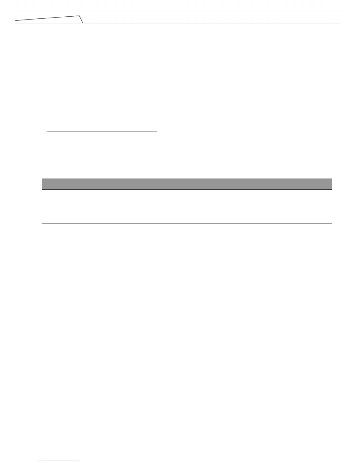
Revision History Table
Revision Date Revised Content
01 October 2018 Original release
02 December 2018 Updated cover page, minor text fixes
Page 7
Regular Payload Series-Hardware Installation Manual TM5 Series 7
1. Product Description
1.1 Product Description
The TM Robot is a six-axis robot with power and force limiting function, which features simple programming,
innovative integrated vision capabilities together with the latest safety functionality.
1.2 How Can I Get Help?
Additional information and resources are available at:
www.adept.com/omron-adept-cobot-manuals
Related Manuals
This manual covers the hardware installation, operation and user maintenance of TM Robot. See the following
table for additional available manuals.
Manual Title Description
Safety Manual Contains safety information for TM Robots.
TMflow Instructions for use of TMflow software.
TMvision Instructions for use of TMvision software.
Page 8
Regular Payload Series-Hardware Installation Manual TM5 Series 8
2. Safety Information
2.1 Overview
The user shall read, understand and abide by the safety information provided in this manual before using the TM
Robot.
2.2 Warning and Caution Symbols
The Table below shows the definitions of the warning and caution levels described in each paragraph of this
Manual. Pay close attention to them when reading each paragraph, and observe them to avoid personal injuries or
equipment damage.
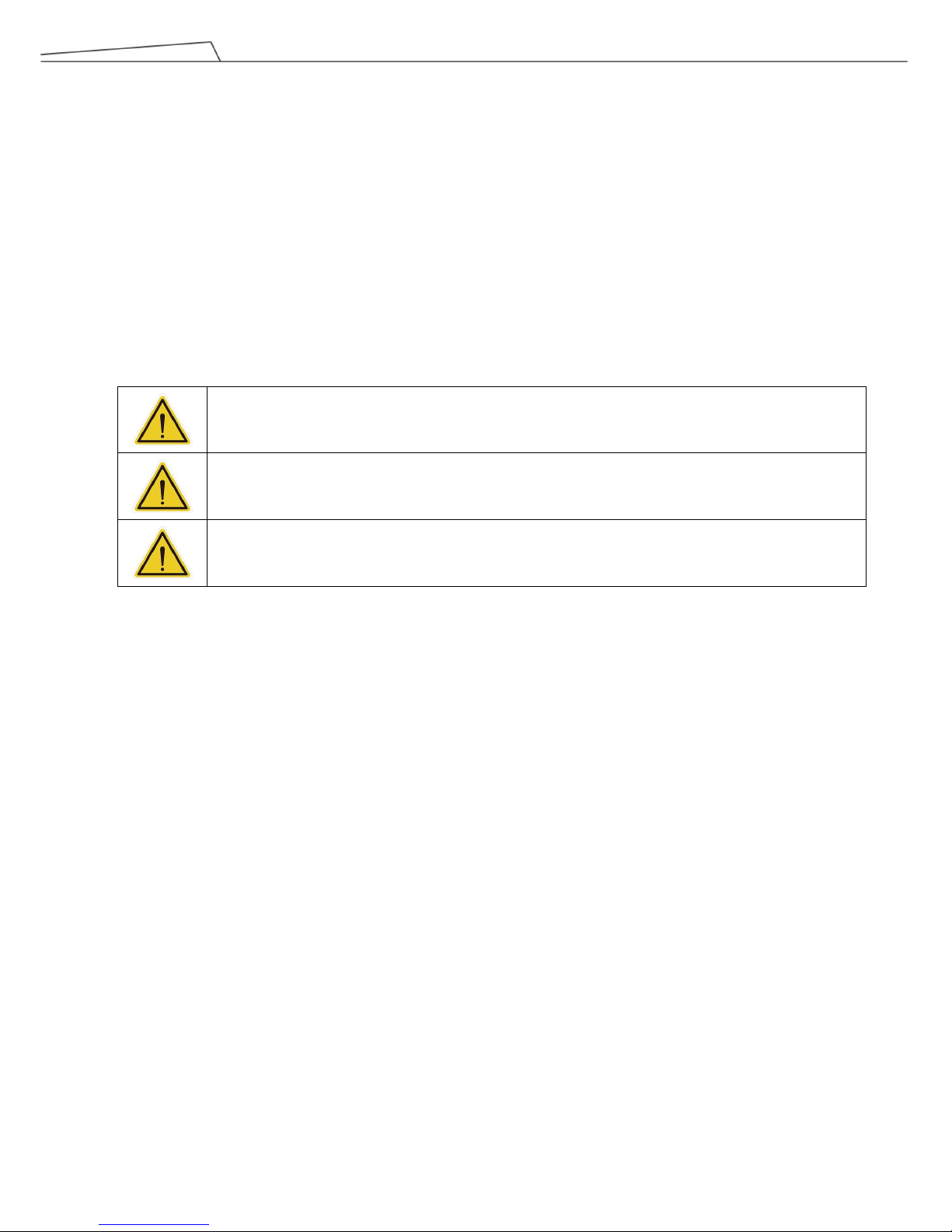
DANGER:
Identifies an imminently hazardous situation which, if not avoided, is likely to result in serious injury,
and might result in death or severe property damage.
WARNING:
Identifies a potentially hazardous situation which, if not avoided, will result in minor or moderate
injury, and might result in serious injury, death, or significant property damage.
CAUTION:
Identifies a potentially hazardous situation which, if not avoided, might result in minor injury,
moderate injury, or property damage.
Page 9
Regular Payload Series-Hardware Installation Manual TM5 Series 9
2.3 Safety Precautions
DANGER:
This product can cause serious injury or death, or damage to itself and other equipment, if the
following safety precautions are not observed.
All personnel who install, operate, teach, program, or maintain the system must read the “Hardware
installation Manual”, “Software Manual”, and “Safety Manual” according to the software and hardware
version of this product, and complete a training course for their responsibilities in regard to the robot.
All personnel who design the robot system must read the “Hardware installation Manual”, “Software Manual”,
and “Safety Manual” according to the software and hardware version of this product, and must comply with
all local and national safety regulations for the location in which the robot is installed.
The TM Robot shall be used according to its intended use.
Results of the risk assessment may require the use of additional risk reduction measures.
If any local or national electrical regulation requires, power to the robot and its power supply must be locked
out and tagged out or have means to control hazardous energy or implement energy isolation before any
maintenance is performed.
Dispose of the product in accordance with the relevant rules and regulations of the country or area
where the product is used.
2.4 Validation and Liability
The information contained herein neither includes how to design, install, and operate a complete robotic arm
system, nor involves the peripherals which may affect the safety of the complete system. The integrators of the
robot should understand the safety laws and regulations in their countries and prevent major hazards from
occurring in the complete system.
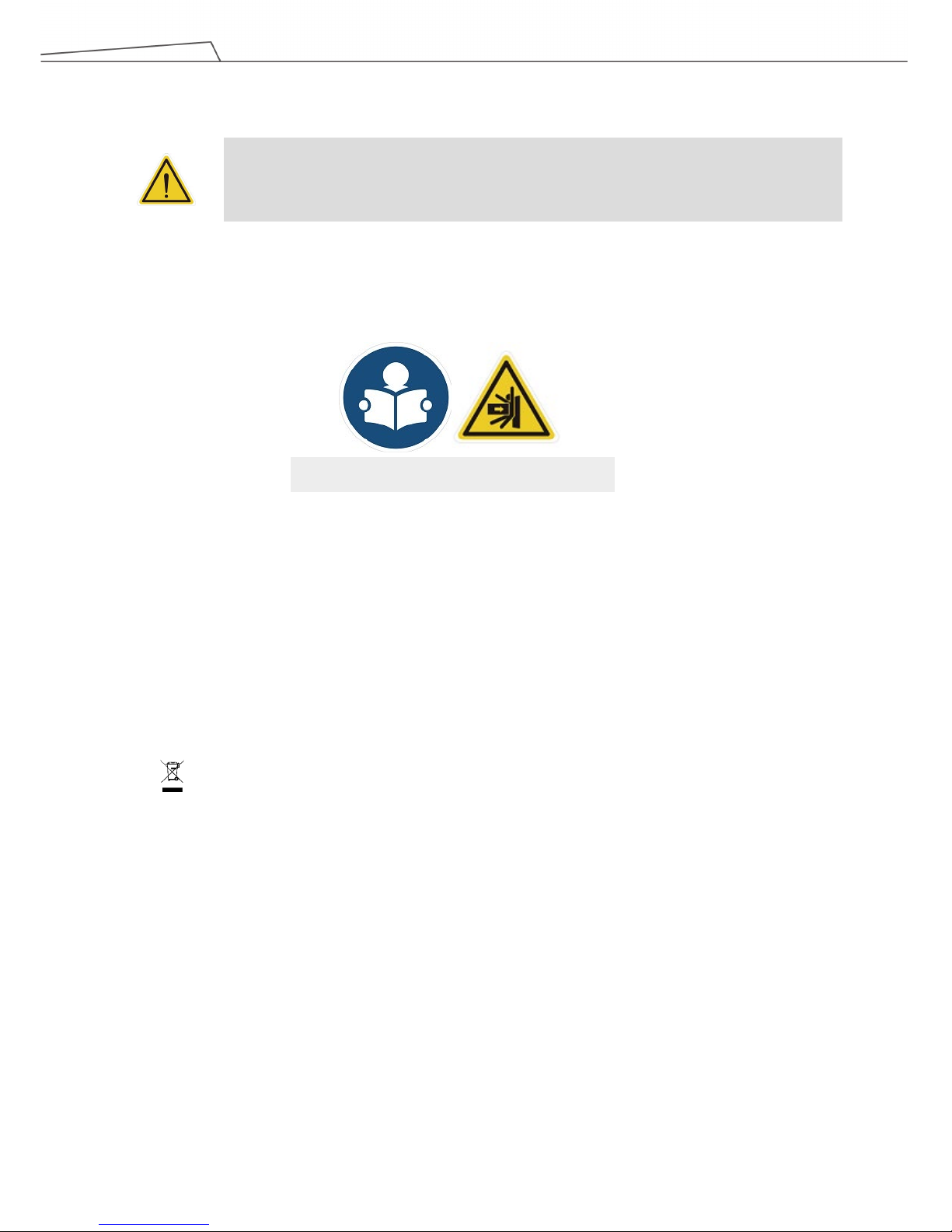
This includes but is not limited to:
Risk assessment of the whole system
Adding other machines and additional safety mechanisms based on the results of the risk assessment
Building appropriate safety mechanisms in the software
Read Manual and Impact Warning Labels
Page 10
Regular Payload Series-Hardware Installation Manual TM5 Series 10
Ensuring the user will not modify any safety-related measures
Ensuring all systems are correctly designed and installed
Clearly labeling user instructions
Clearly marked symbols for installation of the robot arm and the integrator contact details
Collecting all documents into the technology folder, including the risk assessment, and this Manual
CAUTION:
This product is a partly complete machine. The desig
n and installation of the complete system
must comply with the safety standards and regulations in the country of use. The user and
integrators of the robot should understand the safety laws and regulations in their countries
and prevent major hazards from occurring in the complete system.
2.5 Limitations on Liability
Even if the safety instructions are followed, any safety-related information in the Manual shall not be considered
as a guarantee that the product will not cause any personal injury or damage.
2.6 General Safety Warning
1. The actual noise measured in a factory setting is about 49.3dB under without production. (Condition: leave
machine body 1m distance and at 1.6m height from the floor and 8% of maximum speed). If the sound pressure
is over 80 dB(A) while operating, wear proper ear protection.
2. Environmental Conditions:
Ambient air temperature: 0˚C ~ +50˚C
Ambient relative humidity: < 85%
Transportation & Storage condition: -20˚C ~ +60˚C
Transportation & Storage humidity: < 75%
The robot needs to be protected from shock or vibration
Observe ESD precautions when installing or removing robot
2.7 Risk Assessment
Before installing or using this product, the user must first carry out the necessary risk assessment based on the
conditions of use; meanwhile also closely study the potential remaining risk addressed by OMRON. Refer to and
abide by the relevant chapters in Safety Manual in accordance with its’ software and hardware version.
Page 11

Regular Payload Series-Hardware Installation Manual TM5 Series 11
2.8 Emergency Stop
If any accidents occur during the operation of the robot, the user can stop all movement by pressing the
Emergency Switch. When the robot stops, the user must ensure that all fault conditions are eliminated before
manually restarting the robot. The Emergency Switch is only used in critical conditions. To stop the robot during
normal operations use the Stop Button on the system controller. When the user presses the emergency switch,
the TM Robot product will disconnect the power of robot and activate the brake after the robot motion is stopped.
The indication light ring of the robot will not display light, and the three lights from the robot stick will be constantly
blinking.
Once the risk assessment has been conducted, if an Emergency Switch needs to be installed the selected device
must comply with the requirements of ISO 60204-1. Emergency Stop act, factory reset and any other
circumstances, refer and abide by the relevant chapters in Safety Manual in accordance with its’ software and
hardware version.
Page 12
Regular Payload Series-Hardware Installation Manual TM5 Series 12
2.9 Movement without Drive Power
Robot without Drive Power could be found in three circumstances: Emergency stop, when disengaging packaging
posture to initial booting, and power loss. The first two could enter Safe Start up Mode by means of releasing the
Emergency Switch; the latter one is when robot loses external power. Regarding how to operate as well as safety
precautions refer and abide by the relevant chapters in the Safety Manual.
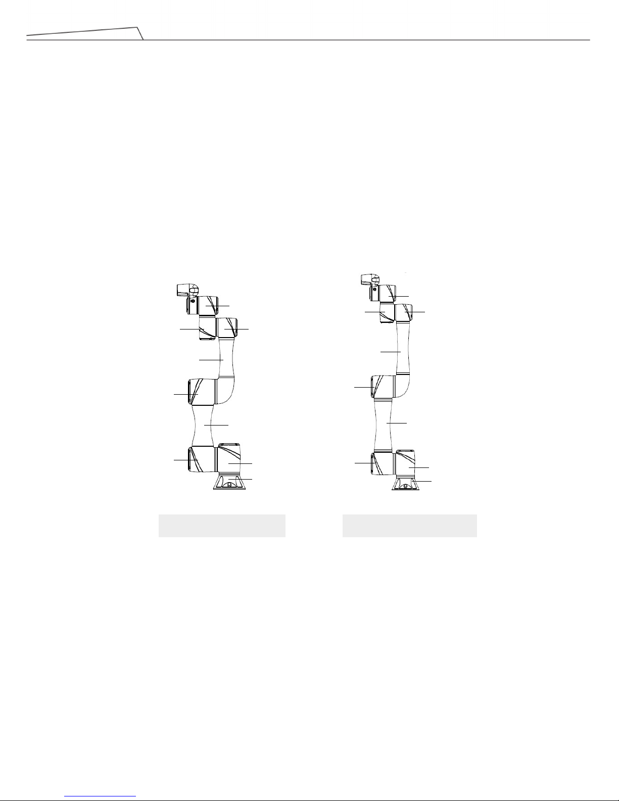
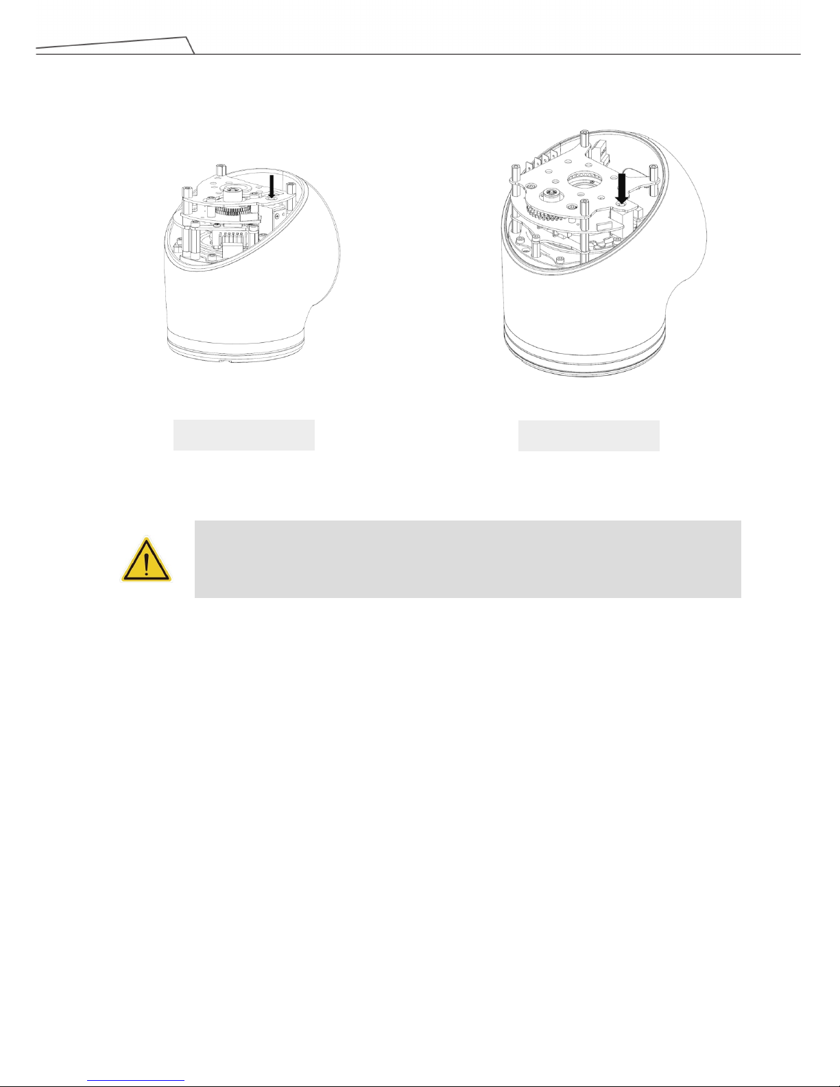
If the robot loses power, and joints need to be moved in order to clear error conditions, you will need to release
the brake for each joint as follows:
1. Remove joint cover screws (M3, Torx-T10) and joint cover.
2. Release the brake by pushing the pin on the brake solenoid shown in the following three figures.
Base
1st Joint
Lower arm
4
th
Joint
6th Joint
3rd Joint
5thJoint
2nd Joint
Upper arm
TM5-700/ TM5M-700
1st Joint
Lower arm
6th Joint
3rd Joint
5th Joint
2nd Joint
Upper arm
TM5-900/ TM5M-900
Base
4
th
Joint
Page 13
Regular Payload Series-Hardware Installation Manual TM5 Series 13
WARNING:
1. Additional supports may be needed when manually releasing the brake due to gravity.
2. When manually moving each robot joint, the movement angle must be within a range of
+/- 45。.
1st/2nd/3rd Joint
4th / 5th /6th Joint
Page 14
Regular Payload Series-Hardware Installation Manual TM5 Series 14
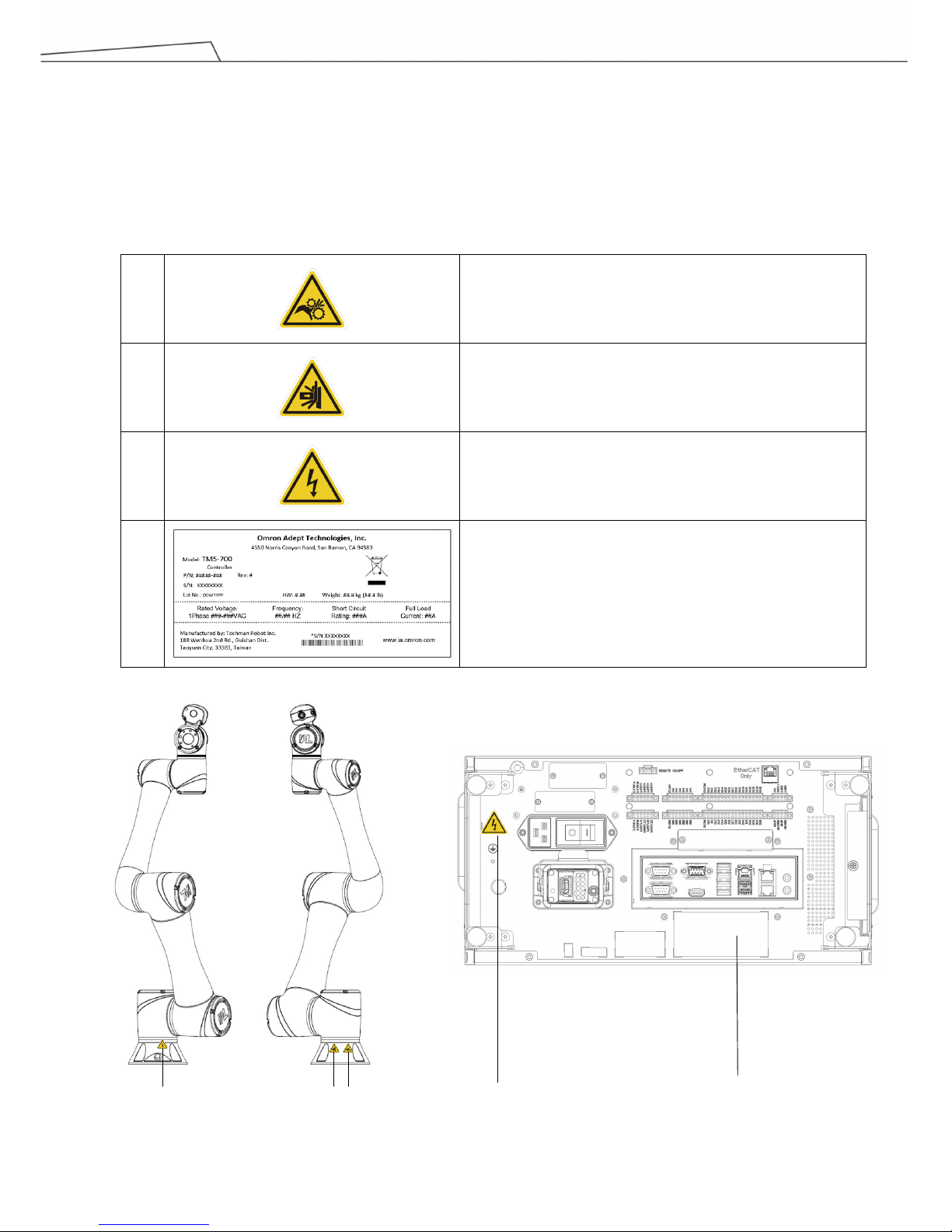
2.10 Labels
The following labels, especially the warning ones, are attached to the locations where specific dangers may occur.
Be sure to comply with description and warnings of the labels when operating to keep the manipulator safely. Do
not tear, damage, or remove the labels. Be very careful if you need to handle the parts where the labels are
attached.
A
Do not put your hand or fingers close to the moving parts
B
Be careful not to be close to the moving parts and nearby
areas to avoid collision
C
Do not touch any internal electric parts to avoid electric
shock
D
Product label
C
D
C B A
Page 15
Regular Payload Series-Hardware Installation Manual TM5 Series 15
3. Transportation and Storage
Transport the TM Robot using its original packing materials. If you will need to transport the TM Robot after
unpacking, store the packing materials in a dry place. Hold both arms of the TM Robot during transportation.
Support the arms while tightening the base screws.
Lift the control box by its handles. Store the cables before transportation.
WARNING:
Pay attention to your posture when moving the arm and control box cartons to avoid back
injury. OMRON will not be liable for any injuries cased during transportation.
WARNING:
This product must be shipped and stored in a temperature-controlled environment, within the
range -20°C to 60°C (-4°F to 140°F). The recommended humidity is up to 75 percent,
non-condensing. It should be shipped and stored in the supplied package, which is designed
to prevent damage from normal shock and vibration. You should protect the package from
excessive shock and vibration.
The product must always be stored and shipped in an upright position in a clean, dry area that
is free from condensation. Do not lay the package on its side or any other non-upright position:
this could damage the product.
Page 16
Regular Payload Series-Hardware Installation Manual TM5 Series 16
4. System Hardware
4.1 Overview
This chapter introduces the mechanical interface of the TM Robot System.
4.2 System Overview
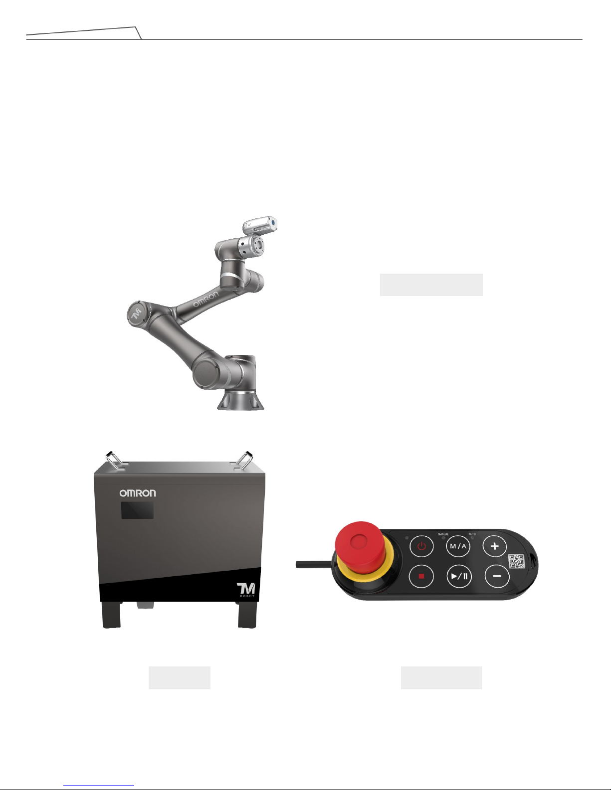
TM Robot is made up of the robot arm and control box (including a robot stick).
Control Box Robot Stick
Robot arm
Page 17
Regular Payload Series-Hardware Installation Manual TM5 Series 17
4.2.1 Robot Arm
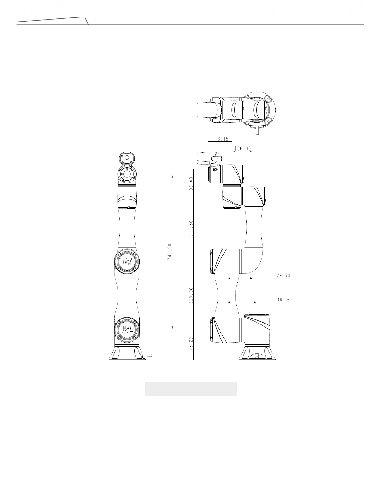
4.2.1.1 Dimension Drawings of Robot
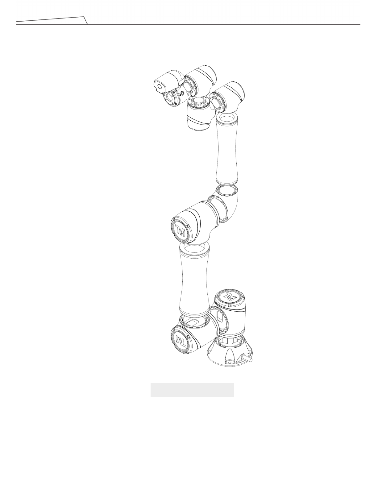
Shown below are the three-view dimension drawings of the robot
TM5-700 / TM5M-700
Page 18
Regular Payload Series-Hardware Installation Manual TM5 Series 18
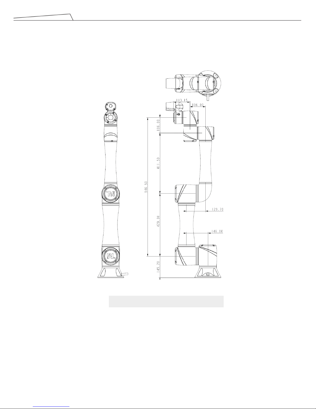
TM5-900 / TM5M-900
Page 19
Regular Payload Series-Hardware Installation Manual TM5 Series 19
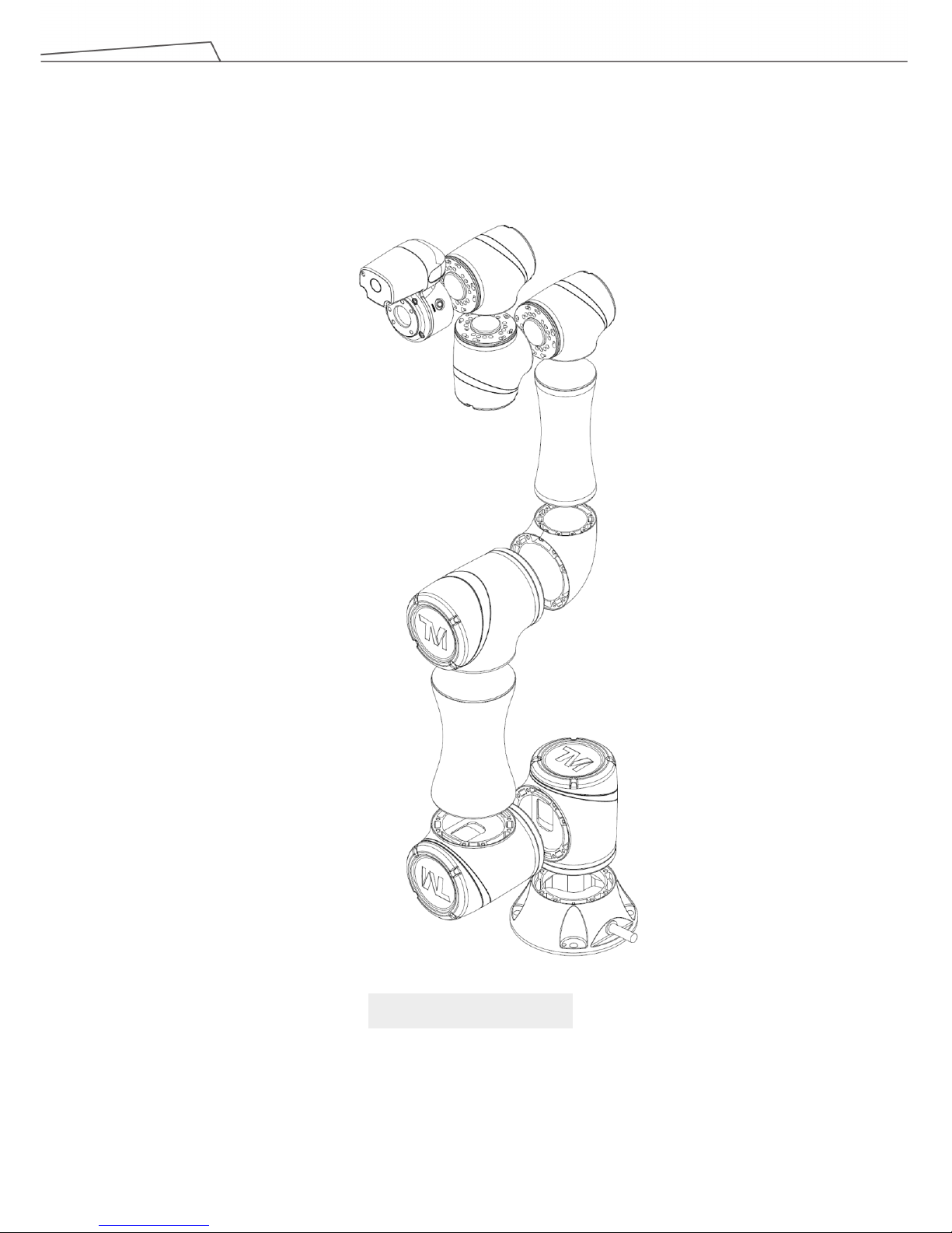
4.2.1.2 Robot Assembly Diagram
Shown below is an illustration of the robot components. To avoid safety risks, do not attempt to
disassemble any component on your own. Contact your local OMRON support for any service request.
TM5-700 / TM5M-700
Page 20
Regular Payload Series-Hardware Installation Manual TM5 Series 20
TM5-900 / TM5M-900
Page 21
Regular Payload Series-Hardware Installation Manual TM5 Series 21
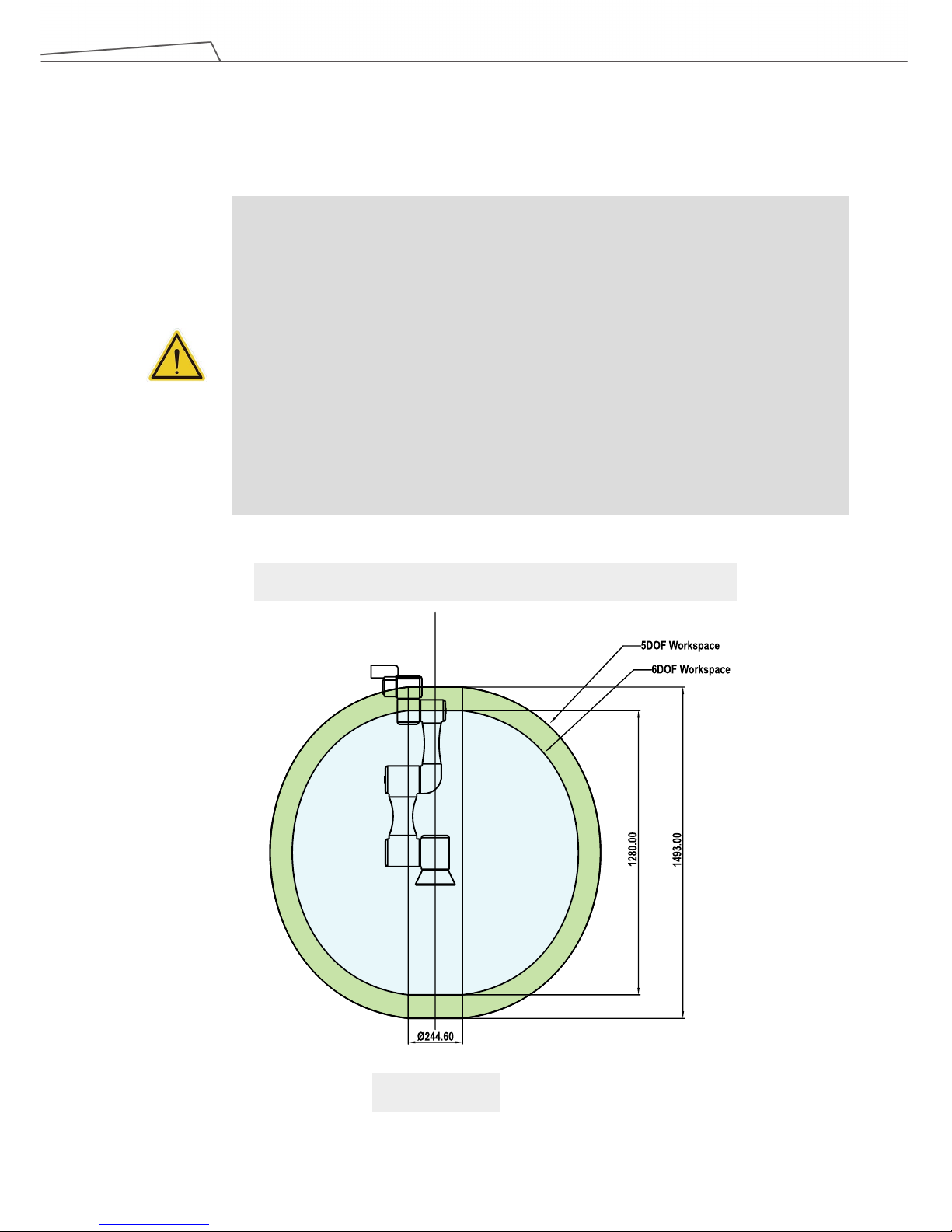
4.2.1.3 Range of Motion
The working spherical (radius) range from the base is 700 mm for the TM5-700 series and 900 mm for
the TM5-900 series.
DANGER:
With the exception of an individual being in full control of robot motion during hand-guiding,
personnel shall be outside the safeguarded space when the robot is in motion while in manual
mode (i.e.teaching).
The emergency stop on the robot stick shall be readily accessible during manual mode. At
least one emergency switch is installed outside of the motion range of the robot. When no
motion limit is set for the robot, the motion range of the robot is equal to the maximum motion
range of the robot arm. You can set a motion limit to avoid the situation whereby all operations
have to be out of the maximum motion range of the robot arm.
The robot stick should be placed in an area that the robot cannot reach. The user should also
make sure that the movement of the robot will not be within any area where personnel will
enter to press any buttons on the robot stick.
TM5-700 / TM5M-700 Movement Range Diagram
Side View
Page 22

Regular Payload Series-Hardware Installation Manual TM5 Series 22
Pictorial view
Operator Position
Warning: Risk of crushing within
the operating area of the arm.
Warning: Risk of collision within
the operating area of the arm.
Top View
Page 23

Regular Payload Series-Hardware Installation Manual TM5 Series 23
TM5-900 / TM5M-900 Movement Range
Pictorial view
Side View
Page 24

Regular Payload Series-Hardware Installation Manual TM5 Series 24
Operator Position
Warning: Risk of crushing within
the operating area of the arm.
Warning: Risk of collision within
the operating area of the arm.
Top View
Page 25

Regular Payload Series-Hardware Installation Manual TM5 Series 25
4.2.1.4 Robot Hazard Zone Diagram and Operator Position Diagram
Shown below is an illustration of the robot hazard zone and operator position diagrams. Do not
operate the robot while anyone is inside of the hazard zone to avoid safety risks.
TM5-700 / TM5M-700
Operator Position
Warning: Risk of crushing within
the operating area of the arm.
Warning: Risk of collision within
the operating area of the arm.
Page 26

Regular Payload Series-Hardware Installation Manual TM5 Series 26
TM5-900 / TM5M-900
Operator Position
Warning: Risk of crushing within
the operating area of the arm.
Warning: Risk of collision within
the operating area of the arm.
Page 27

Regular Payload Series-Hardware Installation Manual TM5 Series 27
4.2.1.5 Payload
The maximum allowed payload of the robot arm is related to its center of gravity offset, which is defined
as the distance from the center point of tool flange to the payload’s center of gravity.
The following figure shows the relationship between payload and the center of gravity offset:
TM5-700 / TM5M-700
Center of gravity offset [mm]
Payload [kg]
TM5-900 / TM5M-900
Center of gravity offset [mm]
Payload [kg]
Page 28

Regular Payload Series-Hardware Installation Manual TM5 Series 28
WARNING:
Use the total weight of the end-effector and the payload to stay within the payload rating of the
robot. Ensure that the system never exceeds that maximum payload.
You should perform a full risk assessment that includes the end-effector and payload samples,
to ensure the safety of the entire system.
4.2.1.6 Robot Arm Installation
The robot can be secured to another surface with the use of (4) M10 screws and washers. The mounting
pattern is shown below. The recommended tightening torque is 40 Nm.
Optional - Two openings for 6 mm position pins are provided for more secure position mounting.
DANGER:
1.
The TM Robot must be securely and tightly screwed down before use. The strength of the
mounting surface must be sufficient.
When operating at high speed, the robot can generate up to 350
N reaction force to the
mounting surface and screws. In order to avoid decreased performance caused by robot slip or
vibration, the recommended mounting surface should be a steel plate at least 20
mm thick, its
flatness should be 0.1
mm or less, its surface roughness should be Rz25 or less. The
recommended screw should be M10 x L30 mm, at least 8.8 strength.
2. Do not immerse TM Robot in water. Installation in water o
r a humid environment will
permanently damage the robot.
Page 29

Regular Payload Series-Hardware Installation Manual TM5 Series 29
4.2.2 Robot End Module
4.2.2.1 End Module Components
GRIPPER Button
Camera module
Flange (ISO 9409-1-50-4-M6)
Digital I/O
Indication Light Ring
Analog I/O
FREE Button
VISION Button
POINT Button
TM5-700/ TM5M-700/ TM5-900 / TM5M-900 End Module Components
Page 30

Regular Payload Series-Hardware Installation Manual TM5 Series 30
Digital l/O
Analog l/O
Camera
4.2.2.2 End Flange Surface
Page 31

Regular Payload Series-Hardware Installation Manual TM5 Series 31
4.2.2.3 End Mounting Caution
The TM5 series uses four M6 threaded holes on the end flange and four M6 screws for mounting tools. A
tightening torque of 9 Nm is recommended. If your application requires higher precision, you can use
two positioning pins with a diameter of 6 mm for a more secure mounting.
4.2.2.4 End Indication Light Ring Table
The Indication Light Ring of the TM Robot has several colors which represent different modes and error
status. Refer to the Software Manual for the definition of the light colors.
DANGER:
Tools must be properly tightened when using this product. Improper tightening may cause the tool
or part to fall out, or even cause personal injury and death.
Page 32

Regular Payload Series-Hardware Installation Manual TM5 Series 32
4.2.3 Control Box
CAUTION:
The control box can be placed on the floor or in your working cell. Note that 5 cm clearance
should be left at both sides for air flow.
4.2.3.1 Robot Stick
The Robot Stick has 6 function buttons, 3 indicator lights, 1 Emergency Switch, and 1 QR-code. Their
functions are as follow:
CAUTION:
When operating the robot stick, do not use other objects than fingers to press the robot stick.
Power Button
Stop Button
Play/Pause Button
- Button
+ Button
M/ A Mode Switch Button
Power Indicator
QR Code Label
Mode Indicator Lights
Emergency Switch
Page 33

Regular Payload Series-Hardware Installation Manual TM5 Series 33
Some of the function buttons offer the following advanced functions:
Items Basic Function
Emergency
Switch
Default emergency button for the robot
Power Button Power initiation (single press)/ Shutdown (long press)
M/ A Mode Switch
Button
Toggle Manual/Auto Mode (single press). See Safety Manual for details.
Play/Pause
Button
Play/Pause Project (single press)
Stop Button Press this button to stop any project.
+- Button
Adjust project speed (single press) under Manual Trial Run Mode.
See Safety Manual for details.
Power Indicator
This indicator shows the robot's power status.
Not on: Switched off
Flashing: Booting
Constant: Startup completed
Mode Indicator
Lights
One is Manual Mode, the other one is Auto Mode. They show the robot's
current operating mode. Once boot up is complete only one will always be
on.
QR Code Label The content of the SSID is also the robot's name in TCP/IP network.
Items Advanced Function
Emergency
Switch
- Press and release, and then wait for 3 seconds to enter Safe Start up
Mode.
- Press and release to enter Safe Start up Mode while booting.
Play/Pause
Button
Play/pause visual calibration operation (single press)
Stop Button Stop visual calibration operation (single press)
+- Button
- Hold to jog the robot at the HMI robot controller page (Hold to Run).
See Safety Manual for details.
- Lock/ Unlock: hold down both add and subtract until the mode indicator
flashes, then follow the sequence "-, +, -, -, +
" to lock/unlock the Robot
Stick (except the Power Button)
Page 34

Regular Payload Series-Hardware Installation Manual TM5 Series 34
4.3 Operating Position of TM Robot with AGV
When TM Robot is placed on an AGV and while the AGV is in operation, the user should pause the TM Robot and
the TM Robot itself should not exceed the footprint of the AGV.
CAUTION:
The robot stick is magnetic so that it can be attached to iron or steel
surfaces. However, the risk
of falling or rotating caused by poor attachment should be taken into account. It is
recommended using the Robot Stick Stand (official accessory) to secure the robot stick. The
Robot Stick Stand should be fix with screws. Always attach the robot stick when it is not in use.
The robot stick should be placed in a way such that the signal cables are routed to avoid
damage caused by pulling.
DANGER:
1. The control box, cables, power signal cables, and robot stick cannot be used when any of
them is in contact with liquids. This may result in personal injury or death.
2. The control box has an IP32 rating but should still is not recommended to be used in dusty
and humid environments. Particular attention should be paid to environments with conductive
dust (such as metal particles).
3. Be noted that the control box can only be at standing pose to have IP32 rating.
AGV Footprint
Top view of TM Robot placed on the AGV
Page 35

Regular Payload Series-Hardware Installation Manual TM5 Series 35
4.4 Working distance and field of view of TM Robot’s EIH camera
The field of view of TM Robot’s EIH camera varies linearly in accordance with the working distance. The minimum
working distance is about 100 mm and the maximum working distance is about 300 mm. The zero working
distance point is approximately 49 mm in front of the flange surface and right behind the center of the protection
lens.
The relation between the working distance and the field of view is listed below,
Working distance (mm)
Field of view (mm)
300 100
Width
281.6 96.9
Height
211.2 72.7
48.6
Working distance = 0
Page 36

Regular Payload Series-Hardware Installation Manual TM5 Series 36
5. Electrical Interface
5.1 Overview
This chapter introduces all electrical interfaces of the robot arm and control box.
5.2 Electrical Warnings and Cautions
The application design and installation of the robot should comply with the following warnings.
DANGER:
1. Ensure all pieces of the equipment are kept dry. If water enters the equipment, disconnect the
power and contact your supplier.
2. Only use the original cables included with the robot. If you need longer cables, contact your
supplier.
3. Ensure that
the robot is properly grounded. If the grounding is not correct, it may cause a fire or
electric shock.
WARNING:
The I/O cables used for the link between the control box and other pieces of equipment
should not be longer than 30 meters, unless testing shows that longer cables are feasible.
Page 37

Regular Payload Series-Hardware Installation Manual TM5 Series 37
5.3 Control Box
WARNING:
Except for USB ports, other interfaces have to be installed while arm is powered off. Do
not install while arm is on to avoid abnormal shutdown.
Control Box I/O configuration
Page 38

Regular Payload Series-Hardware Installation Manual TM5 Series 38
5.3.1 Safety Connector
Provides extension ports for Emergency Stop (ESTOP) & Safeguard Port.
1. ESTOP is a N.C. contact (Normally closed). When any connected ESTOP switch is OPEN, the robot
enters the Emergency STOP state.
2. Safeguard A Port is a N.C. contact (Normally closed). When Safety A switch is OPEN, the robot enters
the Safeguard Pause state.
3. Safeguard B Port is a N.C. contact (Normally closed). When Safety B switch is OPEN, the robot enters
the Safeguard Collaborative Mode state.
Page 39

Regular Payload Series-Hardware Installation Manual TM5 Series 39
If the safety device is used to work with the safety connectors on the TM Robot, the safety relay can be
connected to the safety connector to work as the normally closed switch triggered by the safety device. If a
direct connection between safety device and safety connector on TM Robot is preferred, use a safety
device with PNP outputs. The PNP outputs can be connected to ether “SAFETY_A1 and SAFETY_A2” or
“SAFETY_B1 and SAFETY_B2” to trigger the collaborative mode or pause the robot motion. The PNP
outputs can also be connected to “ESTOP_A and ESTOP_B” to trigger the emergency stop. The example
circuit wiring diagram can be found bellow.
Application settings of the arm safety device
The wiring diagram shows the example of switch type safety device.
Page 40

Regular Payload Series-Hardware Installation Manual TM5 Series 40
The wiring diagram shows the example of PNP output type safety device.
Page 41

Regular Payload Series-Hardware Installation Manual TM5 Series 41
5.3.2 Power Connector
1. During boot, the control box will check for an external 24V input. If none is found, then it will switch to
the internal 24V supply.
2. The control box itself offers a 24V1.5A output (24_EX). If the 24V load exceeds 1.5A, it enters Safe
Mode and disables the 24V output.
3. EX24V provides an external 24V input port. If the load exceeds 1.5A an external power supply can be
used instead. The load on EX24V must not exceed 3.5A.
External
Power Supply
(24V)
24V
■
0V
■
Page 42

Regular Payload Series-Hardware Installation Manual TM5 Series 42
5.3.3 Digital In/Out
Digital input/output each has 16 channels, and its application is connected to the following sections.
5.3.3.1 Digital Input
Inputs can be set to either sink input or source input by selection.
Set to sink input type
When a device such as a transistor output sensor is connected, NPN open collector transistor output
can be used.
Page 43

Regular Payload Series-Hardware Installation Manual TM5 Series 43
Set to Source input type
When a device such as a transistor output sensor is connected, PNP open collector transistor output can
be used.
5.3.3.2 Digital Output:
Outputs can be set to either sink output or source output by selection.
The maximum drive current is 300mA per channel. If the load exceeds 300mA, a relay should be used to
drive it.
Page 44

Regular Payload Series-Hardware Installation Manual TM5 Series 44
Set to sink output type.
Connect DO_COM terminal to the minus side of the power supply.
Page 45

Regular Payload Series-Hardware Installation Manual TM5 Series 45
Set to source output type.
Connect DO_COM terminal to the plus side of the power supply.
Page 46

Regular Payload Series-Hardware Installation Manual TM5 Series 46
5.3.4 Analog In
Analog In only supports a voltage mode and detection range of -10.00 V ~ +10.00 V.
5.3.5 Analog Out
Analog Out only supports a voltage mode and detection range of -10.00 V ~ +10.00 V.
+
-
+
-
Page 47

Regular Payload Series-Hardware Installation Manual TM5 Series 47
5.3.6 System Remote Power ON/OFF
The function of Remote ON/OFF shares the same functionality of the Robot Stick Power Button.
5.3.7 EtherCAT: For EtherCAT Slave I/O Expansion
WARNING:
The robot must be powered off when installing the EtherCAT Slave. Do not plug or unplug the
connector while the robot is on.
5.3.8 USB Port
The USB port of the control box is used for connecting the keyboard, mouse and external storage devices.
External storage devices should only be used for the import/export functions of TM Flow. No other device
than those listed above should be connected. Be noted that the external storage device should be named
“TMROBT”.
Remote ON/OFF
Page 48

Regular Payload Series-Hardware Installation Manual TM5 Series 48
5.4 Tool End I/O Interface
There are two small connectors on the tool end of the robot: The 8-pin connector is for digital I/O The 5-pin
connector is for analog I/O..
5.4.1 I/O Terminals
The tool end 24V has a maximum output current of 1.5A. If overloaded, overload protection is activated
and the robot will turn off the 24V output power.
8-pin digital I/O connectors of Cable
8-pin digital I/O connector of Robot
Pin Wire color Pin define
1 Brown +24v 24V output
2 Red DI_0 Digital Input0
3 Orange DI_1 Digital Input1
4 Yellow DI_2 Digital Input2
5 Green DO_0 Digital Output0
6 Blue DO_1 Digital Output1
7 Purple DO_2 Digital Output2
8 Black +0V +0v
Pin Wire Color Pin Define
1 Brown +24v 24V output
2 Red DI_0 Digital intput0
3 Orange DI_1 Digital intput1
4 Yellow DI_2 Digital intput2
5 Green DO_0 Digital outtput0
6 Blue DO_1 Digital outtput1
7 Purple DO_2 Digital outtput2
8 Black +0V +0V
Page 49

Regular Payload Series-Hardware Installation Manual TM5 Series 49
5-pin analog I/O connector of Cable
5-pin analog I/O connector of Robot
Pin Wire Color Pin Define
1 Black +24V 24V output
2 Brown DI_3 Digital Input3
3 Red DO_3 Digital Output3
4 Orange AI Analog Input
5 Yellow +0V GND
Pin Wire Color Pin Define
1 Black +24V 24V output
2 Brown DI_3 Digital Input3
3 Red DO_3 Digital Output3
4 Orange AI Analog Input
5 Yellow +0V GND
Page 50

Regular Payload Series-Hardware Installation Manual TM5 Series 50
5.4.2 Connecting Tool End Digital Output
The following figure shows how to connect the tool end digital output:
5.4.3 Connecting Tool End Digital Input
The following figure shows how to connect the tool end digital input:
NOTE: If sensors are connected directly then they should be NPN.
5.4.4 Connecting Tool End Analog Input
Input range of -10.00 V ~ +10.00 V.
The following figure shows how to connect the tool end Analog input:
(Because AIN_GND is connected to ground, when AIN is a dead contact, a pressure difference will occur,
which is a normal phenomenon.)
-
+
Page 51

Regular Payload Series-Hardware Installation Manual TM5 Series 51
5.5 Control Box Interfaces
CAUTION:
The ETHERCAT interface can only be used to connect ETHERCAT devices. Improper
connection may cause the robot to stop.
Robot Status Display
USB3.0*2
COM1
Robot Cable Adapter
USB 2.0 *4
HDMI
LAN for GigE Camera*2
EtherCAT
Line-out
Air Filter Screw
AC Adapter
AC Power Switch
Power Remote ON/OFF
COM2
COM3
LAN
Mic-in
I/O Interface
PE
TM5-700 / TM5-900 Series
Page 52

Regular Payload Series-Hardware Installation Manual TM5 Series 52
TM5M-700 / TM5M-900 Series
External Power Supply Remote Control
DC IN Power
DC Power Switch
DC IN for External Power Supply
USB 3.0*2
COM1
Robot Cable Adapter
USB 2.0 *4
HDMI
LAN for GigE Camera*2
EtherCAT
Line-out
Air Filter Screw
Power Remote ON/OFF
COM2
COM3
LAN
Mic-in
I/O Interface
PE
TM5M-700 SEMI / TM5M-900 SEMI Series
External Power Supply Remote Control
DC IN Power
DC Power Switch
DC IN for External Power Supply
USB 3.0*2
COM1
Robot Cable Adapter
USB 2.0 *4
HDMI
LAN for GigE Camera*2
EtherCAT
Line-out
Air Filter Screw
Power Remote ON/OFF
COM2
COM3
LAN
Mic-in
I/O Interface
PE
EMO
Page 53

Regular Payload Series-Hardware Installation Manual TM5 Series 53
5.6 Control Box Power Interface and Robot Interface
5.6.1 Control Box Power Interface
TM5-700 / TM5-900:
The power cable of the control box has an IEC plug. The local power plug is connected to the IEC plug.
TM5M-700/ TM5M-900:
The power cable of the control box has Hirose (HRS) DF60 series connector.
The power supply should be equipped with the following:
• Grounding
• Main fuse
• Residual current device (RCD)
It is recommended to install a master switch on the equipment power supply for robot applications for
servicing and inspection.
AC Adapter
AC Adapter:IEC plug
DC IN Power Connector:( HRS)DF60-3EP-10.16C
DC IN for External Power Supply Connector: Contact OMRON for purchasing
External Power Supply Remote Control Connector:Contact OMRON for
purchasing
DC IN Power
External Power Supply Remote Control
DC IN for External Power Supply
- +
TM5M-700/ TM5M-900
TM5-700 / TM5-900
Page 54

Regular Payload Series-Hardware Installation Manual TM5 Series 54
TM5-700 / TM5-900 electrical specifications:
TM5M-700/ TM5M-900 Series electrical specifications:
*If using DC22~47V power supply, the Robot will automatically limit the total output power
Parameters Minimum value Typical value Maximum value Unit
Input voltage 100 - 240 VAC
External mains fuse
(100V~120V)
- - 15 A
External mains fuse
(220V~240V)
- - 8 A
Input frequency 43 - 63 Hz
Parameters Minimum Value Typical value Maximum value Unit
Input voltage 22 - 60 V (DC)
Power consumption 200 1500 W
DANGER:
1. Ensure that the robot is correctly grounded (electrical grounding).
2. Ensure that the input current of the control box is protected by the Residual Current
Device (RCD) and appropriate fuses.
3. Ensure that all cables are correctly connected before the control box is energized.
Always use genuine power cables correctly.
Page 55

Regular Payload Series-Hardware Installation Manual TM5 Series 55
5.6.2 Robot Interface
The following figure shows the connection interface of the robot. The cables of the robot are connected to
the control box through the interface.
WARNING:
1. When the robot is turned on, do not disconnect cables of the robot. When cables of the
robot are not connected to the connection interface, do not turn on the robot.
2. Do not extend or modify the original cables of the robot.
3. The cables of the robot are only suitable for a fixed installation. If you require a flexible
installation, contact OMRON.
5.6.3 Control Box EMO (Emergency Off ) Interface
Control Box EMO (SEMI Series only) interface is as below,SEMI Emergency Off Switch is connected with
control box through EMO interface.
CAUTION:
For SEMI Series, when SEMI Emergency Off Switch is not connected with EMO, the TM
Robot cannot be booted.
WARNING:
When SEMI Emergency Off Switch is pressed, all power will be cut off immediately.
EMO
(SEMI Series only)
Page 56

Regular Payload Series-Hardware Installation Manual TM5 Series 56
6. Unboxing & Installation
6.1 Overview
These instructions guide the user of the TM Robot through the first set up. The user must thoroughly read and
understand this Guide before performing the operations of this Chapter. Fail to do so may cause serious danger.
6.2 Inspecting the Equipment
6.2.1 Before Unpacking
Carefully inspect all shipping crates for evidence of damage during transit. If any damage is indicated,
request that the carrier's agent be present at the time the container is unpacked
6.2.2 Upon Unpacking
Before signing the carrier’s delivery sheet, compare the actual items received (not just the packing slip)
with your equipment purchase order and verify that all items are present and that the shipment is correct
and free of visible damage,
If the items received do not match the packing slip or are damaged, do not sign the receipt. Contact your
OMRON support as soon as possible.
If the items received do not match your order, contact your OMRON support immediately. Inspect each
item for external damage as it is removed from its container. If any damage is evident, contact your
OMRON support (see HOW Can I Get Help? on 1.2)
Retain all shipping containers and packaging materials. These items may be necessary to settle claims or
at a later date, to relocate equipment.
WARNING:
If this is your first time using the TM Robot, follow instructions in this chapter to perform
installation and initial set up. If the robot has been implemented in the working environment,
please note the following:
1. To avoid potential hazards after changing the original environment setting, verify with
current responsible operator and to back up all necessary software settings and hardware
wirings scheme.
2. Remove all of the control box's external I/O connections including the analog I/O, EtherCAT
port and network port. Remove all air lines or external power lines connected to the optional
equipment before Commissioning.
3. Remove all of the control box's connections to external devices / external storage devices
through USB interface, Serial port, and network interface.
4. Unload any object/end effector attached to the end flange, and any electrical connection
between the end effector and end module / control box of the robot.
5. Unload any hardware attached to the robot arm.
Page 57

Regular Payload Series-Hardware Installation Manual TM5 Series 57
6.3 Unboxing
6.3.1 Carton Types
The TM Robot product is packed in 2 cartons: the robot arm carton and the control box carton, as shown
below:
Robot arm carton:
Control box carton:
Page 58

Regular Payload Series-Hardware Installation Manual TM5 Series 58
6.3.2 Contents of Each Carton
Each carton has the following contents. Check them when you unpack the cartons for the first time. If any
item is missing, contact your vendor.
The robot arm carton contains:
Robot arm
Page 59

Regular Payload Series-Hardware Installation Manual TM5 Series 59
The control box carton contains:
IO cables
(2 packs)
8-pin digital I/O, 5-pin analog I/O
Calibration Plates
(Contains one large and one small
calibration plate)
TM Landmark
(Contains two TM Landmark)
Control box
Page 60

Regular Payload Series-Hardware Installation Manual TM5 Series 60
(1 cable)
Power cable of the control box
(TM5M-700 / TM5M-900)
(4 cables, Type B, I, G, F)
Power cable of the control box
(TM5-700 / TM5-900)
Ground Wire
(1 pack)
SEMI Emergency OFF Switch
(SEMI Series only)
(1 pack)
Page 61

Regular Payload Series-Hardware Installation Manual TM5 Series 61
6.4 Installing Your Robot
The TM Robot arm cannot stand independently after being removed from the carton. Therefore, prepare the
mounting base with the corresponding holes as described in Subsection 4.2.1.6 "Robot Arm Installation" in this
Guide in advance. Then follow these instructions to install the robot.
WARNING:
At the installation site, at least two people should simultaneously perform installation of the
robot, otherwise you risk robot arm damage or personal injury. Do not install the robot alone.
WARNING:
Do not attempt to move any robot links until the robot has been secured in position. Failure to
comply could result in the robot falling and causing either personnel injury or equipment
damage.
6.4.1 Remove the Control Box
After checking the contents, remove the contents in order and perform installation.
Control box carton:
- Remove the Calibration Plates and TM Landmark
- Remove the power cable of the control box
- Remove the control box (At least two people should remove the control box from the carton. For the
correct holding positions, as shown below.)
- Connect the power cable to the control box
- Place the control box near the robot base
Page 62

Regular Payload Series-Hardware Installation Manual TM5 Series 62
The control box should be carried by at least two people. One should hold on to the control box handles,
while the other should carry the foot stands. Before handling, the cable of the robot stick should not be
pulled to avoid any performance degradation.
WARNING:
At this stage, do not connect the power cable of the control box to any electrical outlet, or it
may cause equipment damage.
Page 63

Regular Payload Series-Hardware Installation Manual TM5 Series 63
6.4.2 Verification Before Removal of the Robot Arm
The TM Robot arm cannot stand independently after being removed from the carton. Prepare four screws
(M10 *4) that used to attach the robot to the base near the robot base in advance. If the base is designed
with corresponding pinholes, mount them to the base.
6.4.3 Removal of the Robot Arm and Tightening
At least two people should remove the robot arm from the carton. For the correct holding positions, see
the figure shown below. Place the robot on the mounting base. If it is designed with connection pins, align
the pinholes of the robot base module. Tighten two locking screws with metal washers for the robot base
that are diagonally across from each other, and then tighten the other two locking screws..
Follow the tightening torque recommended in Subsection 4.2.1.6 "Robot Arm Installation" in this Guide.
The Robot Arm itself should be handled with at least two people. One person should carry the Lower arm
and Upper arm, and the other should hold on to the position between the base and 1
st
Joint as well as the
6
th
Joint. Before the Robot Base is fastened with screws tightly, the Robot Arm should always be
supported to avoid tipping.
Page 64

Regular Payload Series-Hardware Installation Manual TM5 Series 64
WARNING:
When the robot is installed to the base, make sure two people work together to install it. If it is
designed with pinholes, pay attention to your safety to avoid pinching. If you do not have
connection parts at hand, such as the connecting pins, screws do not leave the robot without
completely tightening it (with the 4 screws completely tightened). One person should
continuously support the robot arm while the other person goes to get required parts.
Otherwise, the robot arm may tip, result in equipment damage or personal injury.
Page 65

Regular Payload Series-Hardware Installation Manual TM5 Series 65
6.4.4 Connect the Robot and Control Box
Connect the power cable from the control box to the robot, and then connect the power cable from AC
power to the control box to boot up the controller.
WARNING:
1. Ensure that all cables are correctly connected before the control box is energized. Always
use genuine power cables correctly.
2. When the robot is turned on, do not disconnect cables of the robot. When cables of the
robot are not connected to the connection interface, do not turn on the robot.
3. Do not extend or modify the original cables of the robot.
Page 66

Regular Payload Series-Hardware Installation Manual TM5 Series 66
7. Maintenance and Repair
The following table gives a summary of the preventive maintenance procedures and guidelines:
Items Period Remark
Warning, Safety labels 1 week
Ensure labels are present and legible.
Replace them if necessary.
Check Filter 1 month Replace filter every 3 months.
Check Emergency Switch 1 month
Press the Emergency Switch and the IO
E-Stop in open-loop status. Verify that each
shuts off power.
Check Safeguard Ports (A, B) 1 month
When the Safeguard A Port is in the
open-loop state, the indication light of current
mode will be constantly flashing.
When the Safeguard B Port is in the
open-loop state, the purple light will be
alternating between the indication light of the
current mode.
Check Robot Mounting Screws 3 months Follow ”4.2.1.6 Robot Arm Installation”
EMO button (SEMI version only) 6 months
Press the EMO button. Verify that power
shuts off.
Only the legal distributor or authorized service center should repair the TM Robot. The user should not repair it by
himself or herself.
DANGER:
Before performing maintenance or service record the details of each setting for the robot for
normal operation. Make
sure that each setting satisfies the original conditions before resuming
normal operation, including but not limited to:
- Safety Software Settings
- Safety I/O
- Preset operation project
- TCP Settings
- I/O Settings
- I/O Wiring
Page 67

Regular Payload Series-Hardware Installation Manual TM5 Series 67
Appendix A. Technical Specifications
Model TM5-700 TM5-900 TM5M-700 TM5M-900
Weight
22.1 kg 22.6 kg 22.1 kg 22.6 kg
Payload
6 kg 4 kg 6 kg 4 kg
Reach
700 mm 900 mm 700 mm 900 mm
Typical Speed
1.1 m/s 1.4 m/s 1.1 m/s 1.4 m/s
Joint
ranges
J1,J6 +/- 270°
J2,J4,J5 +/- 180°
J3 +/- 155°
Speed
J1~J3 180°/s
J4~J6 225°/s
Repeatability
+/- 0.05 mm
Degrees of freedom
6 rotating joints
I/O ports
Control box
16
16
2
1
Tool conn.
4
4
1
0
Digital in
Digital out
Analog in
Analog out
I/O power supply
24V 1.5A for control box and 24V 1.5A for tool
IP classification
Robot Arm: IP54 ; Control Box: IP32
Power consumption
Typical 220 watts
Temperature
The robot can work in a temperature range of 0-50°C
Power supply
100-240 VAC, 50-60 Hz DC22~60VDC
I/O Interface
3×COM, 1×HDMI, 3×LAN, 4×USB2.0, 2×USB3.0
Certification
CE, SEMI S2 (optional)
Robot Vision
Eye in Hand (Built in)
1.2M/5M pixels, color camera
Eye to Hand (Optional)
Support Maximum 2 GigE cameras
Page 68

68
I623-E-02
19888-100 B
1218 (1018)
 Loading...