

Omron E3s-a Sensor
Built-in Amplifier Photoelectric Sensor (Medium Size)
E3S-A
Be sure to read Safety Precautions
on page 10.
Ordering Information
CSM_E3S-A_DS_E_5_1
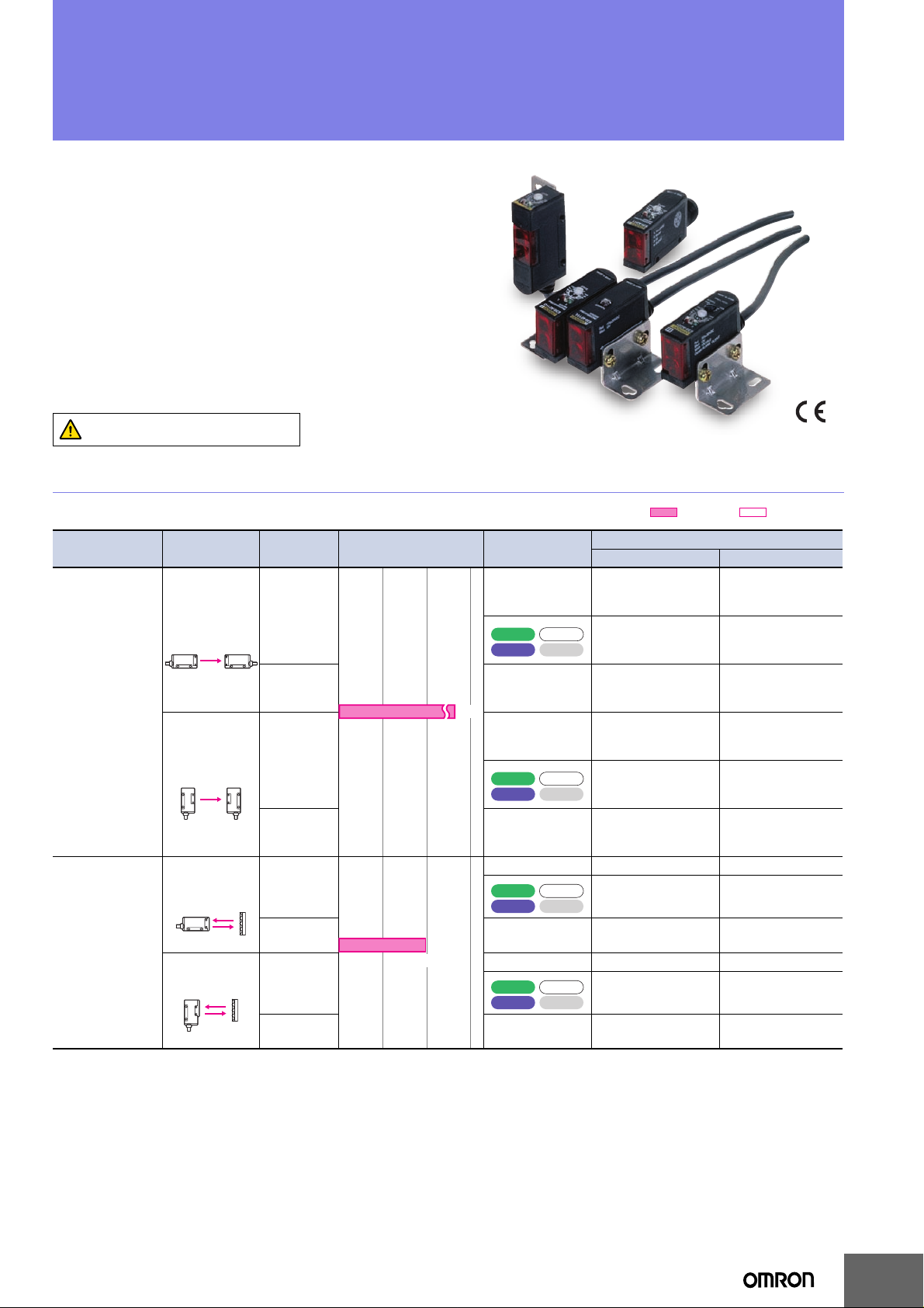
Built-in Amplifier Photoelectric Sensors
Sensing method Appearance
Horizontal
Through-beam
Sensors *1
Vertical
Horizontal
Retro-reflective
Sensors
Vertical
*1.Through-beam Sensors are normally sold in sets that include both the Emit ter and Receiver.
Orders for individual Emitters and Receivers are accepted.
*2.Values in brackets are the minimum required distance between the Sensor and Reflector.
Connection
method
Pre-wired
Connector
(M12)
Pre-wired
Connector
(M12)
Pre-wired
Connector
(M12)
Pre-wired
Connector
(M12)
Sensing distance Functions
Self Diagnosis
7 m
Self Diagnosis
Self Diagnosis
2 m
(100 mm)
*2
Self Diagnosis
Red light Infrared light
Model
NPN output PNP output
Timer
Timer
---
Turbo
External
Diagnosis
Emitter
E3S-AT11-L
Receiver
E3S-AT11-D
E3S-AT21
Emitter
E3S-AT21-L
Receiver
E3S-AT21-D
E3S-AT16
E3S-AT11
---
Emitter
Receiver
E3S-AT16-L
E3S-AT16-D
E3S-AT61
---
Turbo
External
Diagnosis
Emitter
E3S-AT61-L
Receiver
E3S-AT61-D
E3S-AT71
Emitter
E3S-AT71-L
Receiver
E3S-AT71-D
E3S-AT66
---
Emitter
Receiver
E3S-AT66-L
E3S-AT66-D
E3S-AT31
Emitter
Receiver
E3S-AT41
Emitter
Receiver
E3S-AT36
Emitter
Receiver
E3S-AT81
Emitter
Receiver
E3S-AT91
Emitter
Receiver
E3S-AT86
Emitter
Receiver
--- E3S-AR11 E3S-AR31
Timer
Turbo
External
Diagnosis
E3S-AR21 E3S-AR41
--- E3S-AR16 E3S-AR36
--- E3S-AR61 E3S-AR81
Timer
Turbo
External
Diagnosis
E3S-AR71 E3S-AR91
--- E3S-AR66 E3S-AR86
E3S-AT31-L
E3S-AT31-D
E3S-AT41-L
E3S-AT41-D
E3S-AT36-L
E3S-AT36-D
E3S-AT81-L
E3S-AT81-D
E3S-AT91-L
E3S-AT91-D
E3S-AT86-L
E3S-AT86-D
1
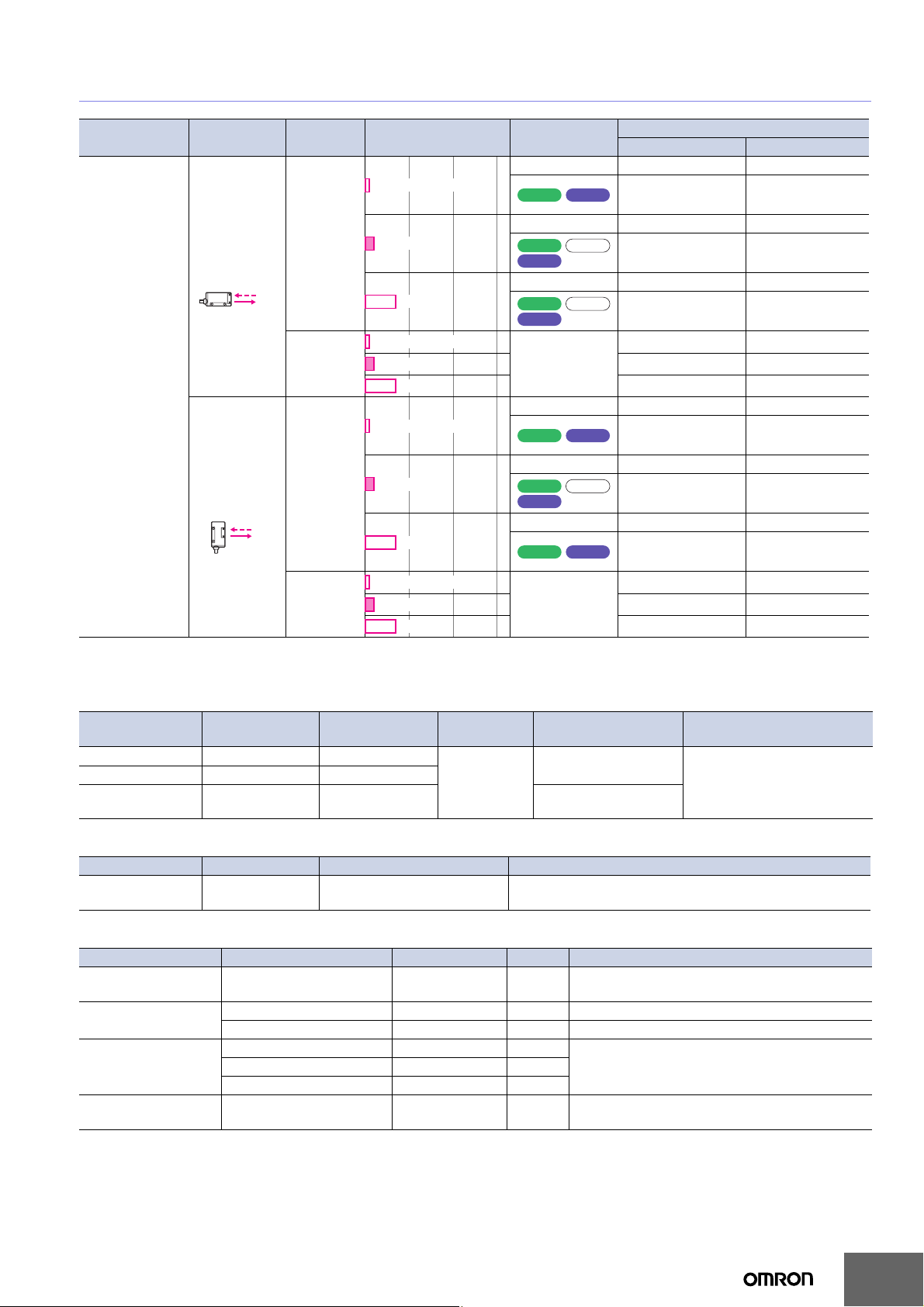
E3S-A
Sensing method Appearance
Horizontal
Diffuse-reflective
Sensors
Vertical
Connection
method
Pre-wired
Connector
(M12)
Pre-wired
Sensing distance Functions
--- E3S-AD13 *3E3S-AD33
100 mm (wide view)
Timer
--- E3S-AD11 E3S-AD31
200 mm
Timer
Self Diagnosis
--- E3S-AD12 E3S-AD32
700 mm
Timer
Self Diagnosis
100 mm (wide view)
200 mm
---
700 mm
--- E3S-AD63 *3E3S-AD83
100 mm (wide view)
Timer
--- E3S-AD61 E3S-AD81
200 mm
Timer
Self Diagnosis
--- E3S-AD62 E3S-AD82
700 mm
Timer
Self Diagnosis
Turbo
Turbo
Self Diagnosis
Turbo
Self Diagnosis
Model
NPN output PNP output
E3S-AD23 E3S-AD43
E3S-AD21 E3S-AD41
E3S-AD22 E3S-AD42
E3S-AD18 E3S-AD38
E3S-AD16 E3S-AD36
E3S-AD17 E3S-AD37
E3S-AD73 E3S-AD93
E3S-AD71 E3S-AD91
E3S-AD72 E3S-AD92
Connector
(M12)
200 mm
700 mm
*3.The following models are available with 200-mm sensing distances: E3S-AD14 and E3S-AD64.
100 mm (wide view)
---
E3S-AD68 E3S-AD88
E3S-AD66 E3S-AD86
E3S-AD67 E3S-AD87
Accessories (Order Separately)
Insert-type Long Slit
Slit width Sensing distance
0.5 mm × 11.1 mm
1 mm × 11.1 mm
2 mm × 13.6 mm
500 mm
1.1 m
2.5 m
Mutual Interference Prevention Filters
Sensing distance Model Quantity Remarks
2.4 m E39-E6
Reflectors/Other Accessories
Name Sensing distance (typical) Model Quantity Remarks
Reflectors
Small Reflectors
2 m (100 mm) *
(rated value)
1.3 m (100 mm) * E39-R3 1 ---
600 mm (70 mm) * E39-R4 1 ---
450 mm (100 mm) * E39-RS1 1
Tape Reflectors
900 mm (100 mm) * E39-RS3 1
Optical Axis
Confirmation Reflector
Note: When using any Reflector other than the provided one, use a sensing distance of approximately 0.7 times the typical value as a guide.
*Values in brackets are the minimum required distance between the Sensor and Reflector.
Minimum sensing
object (typical)
Model Quantity Remarks
0.2-mm dia.
0.4-mm dia.
E39-S46
0.8-mm dia.
2 of each for Emitter/Receiver
(4 Filters total)
Can be used with the E3S-AT@@ Through-beam Sensor.
➜ Page 10
E39-R1 1 Provided with E3S-AR@@ Retro-reflective Sensor.
--- E39-R5 1
1 of each for Emitter/
Receiver (4 Slits total)
1 of each for Emitter/
Receiver (2 Slits total)
Slits can be used with the E3SAT@@ Through-beam
Sensor.➜Page 10
Enables MSR function.700 mm (100 mm) * E39-RS2 1
Used to check optical axis for the E3S-AT@@
Through-beam Sensor.
2
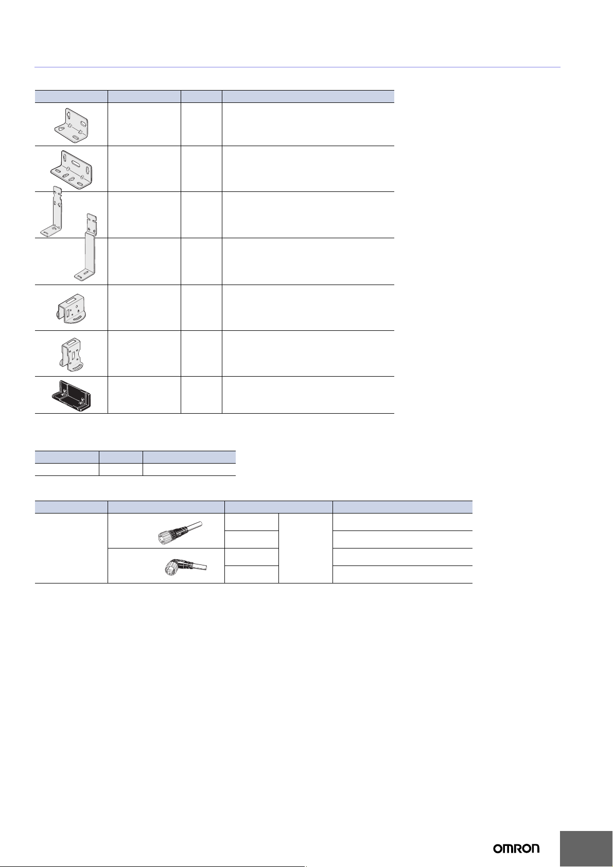
Mounting Brackets/Other
Appearance Model Quantity Remarks
E39-L69 1 Provided with E3S-A Horizontal Sensors.
E39-L70 1 Provided with E3S-A Vertical Sensors.
E3S-A
E39-L59 1
E39-L81 1
E39-L97 1
E39-L98 1
E39-L60 1
Note: If a Through-beam Model is used, order two Mounting Brackets, one for the Emitter and one for the Receiver.
Provided with E3S-A Vertical Pre-wired
Sensors.
Provided with E3S-A Vertical Connector
Sensors.
Protective Cover for Horizontal Sensors
Note: When mounting Sensors with Connectors, the
Sensor I/O Connector will come into contact
with the Bracket. Mount the Sensor with care.
Protective Cover for Vertical Sensors
Note: When mounting Sensors with Connectors, the
Sensor I/O Connector will be longer. Mount the
Sensor with care.
Close Mounting Plate:
Provided with E3S-A Connector Sensors.
Sensors I/O Connectors
Model Quantity Remarks
E39-G2 1 Provided with product.
Sensors I/O Connectors
Cable Appearance Cable type Model
Straight
Standard
L-shaped
Note: When using Through-beam models, order one connector for the Receiver and one for the Emitter.
2 m
5 m
2 m
5 m
3-wire
XS2F-D421-DC0-A
XS2F-D421-GC0-A
XS2F-D422-DC0-A
XS2F-D422-GC0-A
3
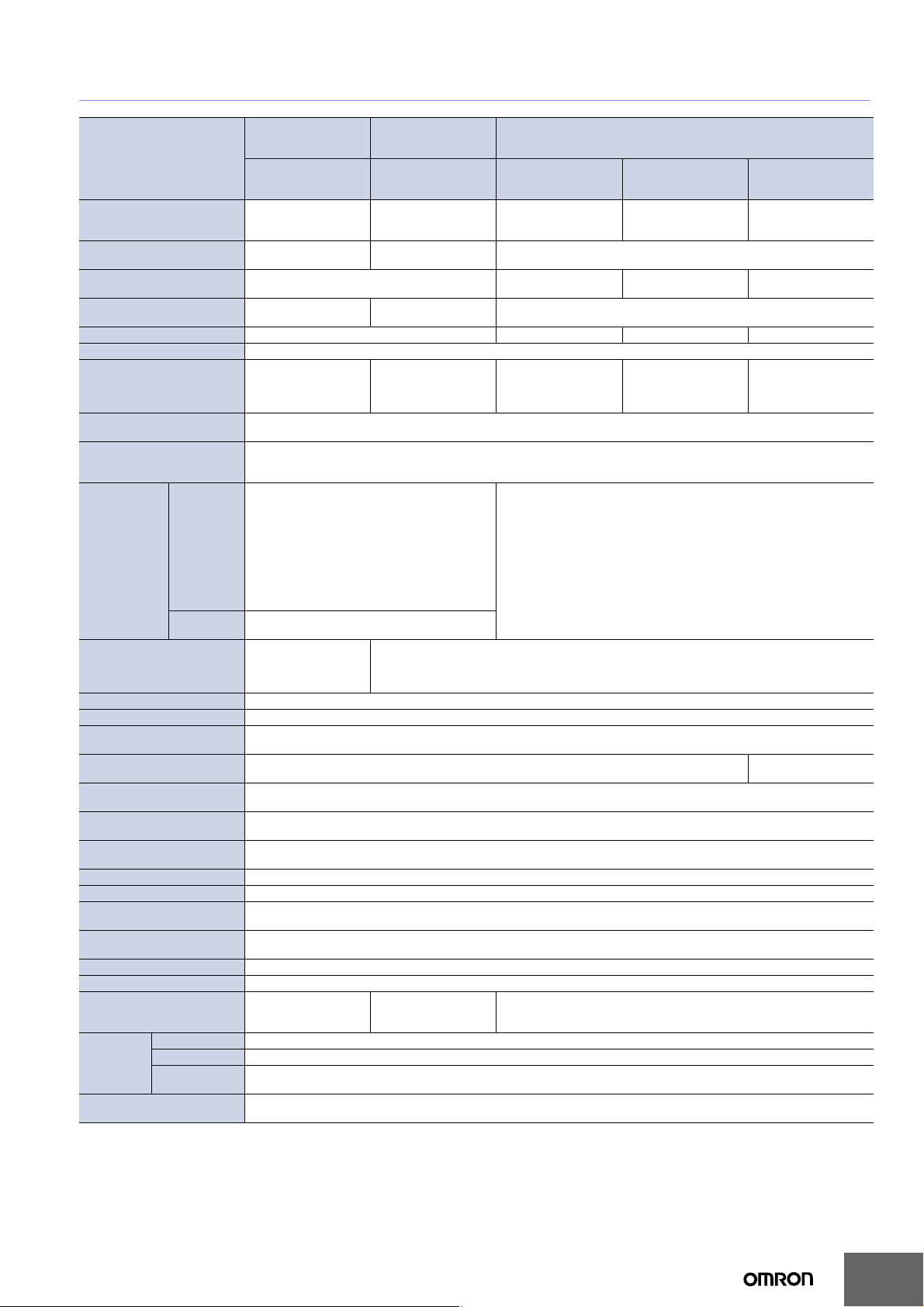
Ratings and Specifications
E3S-A
Sensing method
Item
Sensing distance 7 m
Standard sensing object
Differential travel ---
Directional angle
Light source (wavelength) Red LED (700 nm) Infrared LED (880 nm) Red LED (700 nm) Infrared LED (880 nm)
Power supply voltage 10 to 30 VDC, including ripple (p-p) 10%
Current consumption
Control output
Self-diagnostic output (Only
on Sensors with self-diagnostic outputs)
External
diagnostic
input
(Only on
Sensors with
external
diagnostic
outputs)
Protection circuits
Response time Operation or reset: 0.5 ms max.
Sensitivity adjustment Two-turn endless adjuster with an indicator
Timer function (Only on Sen-
sors with the timer function)
Turbo function (Only on Sen-
sors with the turbo function)
Ambient illumination (Receiv-
er side)
Ambient temperature
Ambient humidity
Insulation resistance 20 MΩ min. at 500 VDC between current-carrying parts and case
Dielectric strength 1,000 VAC, 50/60 Hz for 1 min. between current-carrying parts and case
Vibration resistance
(destruction)
Shock resistance
(destruction)
Degree of protection IEC IP67; NEMA: 4X (indoors only) *2
Connection method Pre-wired (standard length: 2 m) or M12 connector
Weight (packed state)
Case PBT
Material
Accessories
*1.Values in brackets are the minimum required distance between the Sensor and Reflector.
*2.National Electrical Manufacturers Association
Lens Denatured polyallylate
Mounting
Bracket
Model
Input
voltage
Response
time
Through-beam
Sensors
E3S-AT11, 16, 21, 31,
36, 41, 61, 66, 71, 81,
86, 91
Opaque:
10-mm dia. min.
Both Emitter and
Receiver: 3° to 15°
Both Emitter and
Receiver: 20 mA max.
(plus approx. 15 mA with
turbo function)
Load power supply voltage: 30 VDC max., Load current: 100 mA max. (residual voltage: 1 V max.)
Open-collector output (NPN or PNP depending on model), Light-ON/Dark-ON selectable
(Only Sensors with self-diagnostic function) Load power supply voltage: 30 VDC max.,
Load current: 50 mA max. (residual voltage: 1 V max.),
Open-collector output (NPN or PNP depending on model)
NPN
with Emitter OFF: 0 V short-circuit or 1.5 V max.
(source current: 1 mA max.)
with Emitter ON: Open
(leakage current: 0.1 mA max.)
PNP
with Emitter OFF: +DC short-circuit or −1.5 VDC
max. (sink current: 3 mA max.)
with Emitter ON: Open
(leakage current: 0.1 mA max.)
0.5 ms max.
Power supply reverse
polarity protection,
Output short-circuit
protection
0 to 100 ms OFF-delay variable adjuster
Yes (with turbo switch) --Incandescent lamp: 5,000 lx max.
Sunlight: 10,000 lx max.
Operating: −25°C to 55°C (with no icing or condensation)
Storage: −40°C to 70°C (with no icing or condensation)
Operating: 35% to 85% (with no condensatio n)
Storage: 35% to 95% (with no condensation)
10 to 55 Hz, 1.5-mm double amplitude for 2 hours each in X, Y, and Z directions
Destruction: 500m/s
Pre-wired cable:
Approx. 150 g
Connector: Approx. 70 g
Stainless steel (SUS304)
Mounting bracket (with screws), Sensitivity adjustment driver, Sensitivity adjusting knob, Instruction sheet, Close mounting plate
(only for Sensors with connectors), and Reflector (only for Retro-reflective Sensors)
2
Retro-reflective
Sensors
(with MSR function)
E3S-AR11, 16, 21, 31,
36, 41, 61, 66, 71, 81,
86, 91
2 m (100 mm) *1
(When using E39-R1)
Opaque:
75-mm dia. min.
3 to 10° ---
30 mA max. (plus
approx. 15 mA with
turbo function)
Power supply reverse polarity protection, Output short-circuit protection, Mutual interference prevention
, 3 times each in X, Y, and Z directions
Pre-wired cable:
Approx. 110 g
Connector: Approx. 60 g
E3S-AD13, 18, 23, 33,
38, 43, 63, 68, 73, 83,
88, 93
100 mm (wide view)
(white paper 100 ×
100 mm)
20% max. of sensing
distance
35 mA max.
Pre-wired cable: Approx. 90 g
Connector: Approx. 50 g
Diffuse-reflective Sensors
E3S-AD11, 16, 21, 31,
36, 41, 61, 66, 71, 81,
86, 91
10 to 200 mm
(white paper 100 ×
100 mm)
---
10% max. of sensing
distance
30 mA max. (plus
approx. 15 mA with
turbo function)
---
E3S-AD12, 17, 22, 32,
37, 42, 62, 67, 72, 82,
87, 92
700 mm
(white paper 200 ×
200 mm)
20% max. of sensing
distance
35 mA max.
4
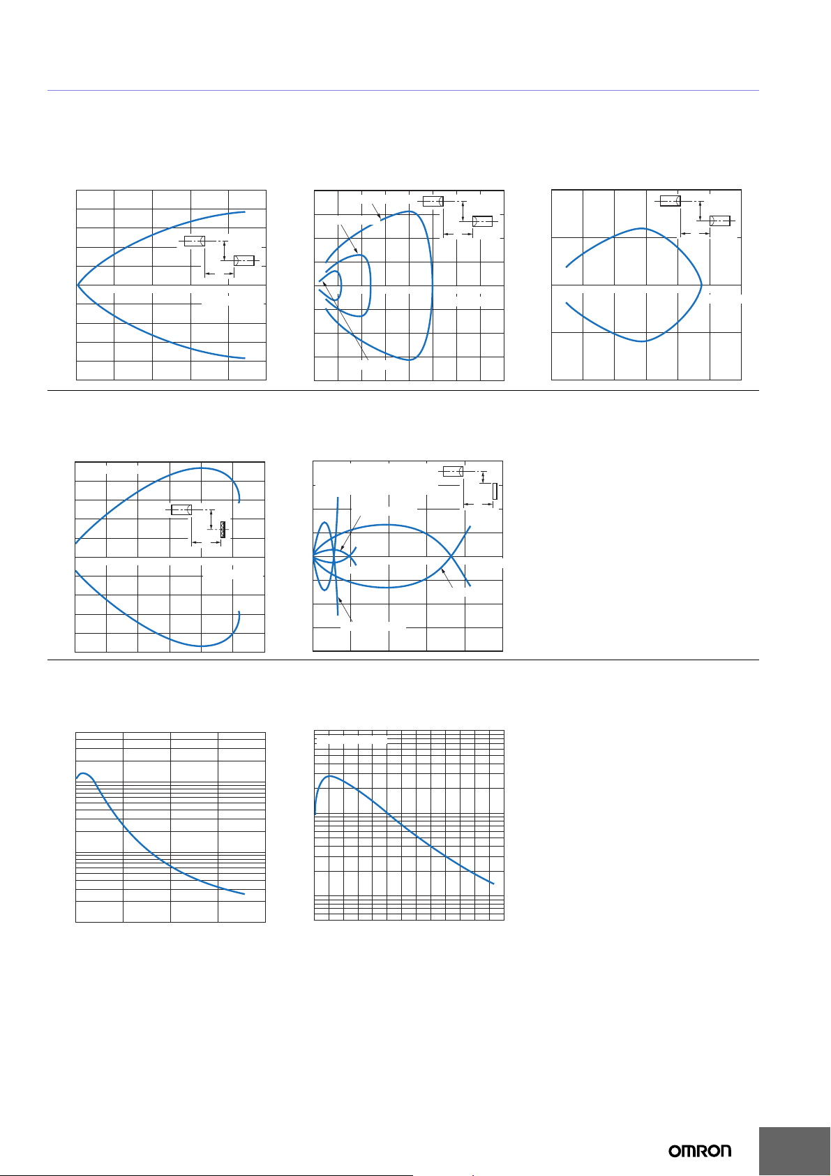
Engineering Data (Typical)
Parallel Sensing Range
Through-beam Sensors Through-beam Sensors Through-beam Sensors
E3S-AT@@ E3S-AT@@ + E39-S46
(Slit Sold Separately)
500
400
300
200
Distance Y (mm)
100
0
−100
−200
−300
−400
−500
Y
X
2 4 6 8
Distance X (m)
200
100
Slit width: 2 mm
Slit width: 1 mm
Distance Y (mm)
0
1 2 3 4 5 6 7 8
−100
Slit width: 0.5 mm
−200
Y
X
Distance X (m)
Parallel Sensing Range Sensing Range
Retro-reflective Sensors Diffuse-reflective Sensors
E3S-AR@@ + E39-R1 (with Reflector) E3S-AD@1/AD@2/AD@3/AD@6/AD@7/AD@8
100
E39-R1 Reflector
80
60
40
Distance Y (mm)
20
0
0.5 1.0 1.5 2.0 2.5
−20
−40
−60
−80
−100
Y
X
Distance X (m)
40
Sensing object: white paper
@1/@3/@6/@8: 100 × 100 mm
E3S-AD
30
20
Distance Y (mm)
10
0
−10
−20
−30
−40
E3S-AD
200
E3S-AD@3/@8
@2/@7: 200 × 200 mm
E3S-AD@1/@6
400 600 800
E3S-AD@2/@7
X
Distance X (m)
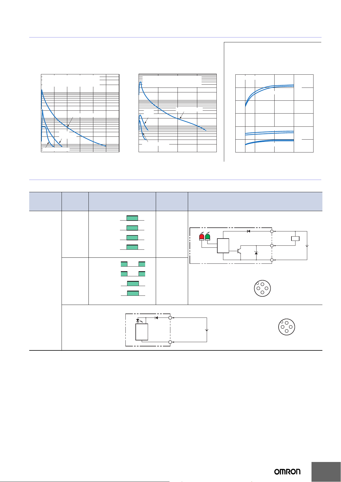
Excess Gain vs. Set Distance
Through-beam Sensors Retro-reflective Sensors
E3S-AT@@ E3S-AR@@ + E39-R1 (with Reflector)
500
300
100
50
30
Excess gain ratio (times)
10
5
3
Operating
1
level
0 3 5 7 10
Distance (m)
100
E39-R1 Reflector
50
30
10
Excess gain ratio (times)
5
3
Operating
1
level
0 0.2 0.4 0.6 0.8 1 1.2 1.4 1.6 1.8 2 2.2 2.4 2.6
Distance (m)
E3S-AT@@ + E39-E6
(Filter Sold Separately)
200
100
Distance Y (mm)
0
−100
−200
Y
1 2 3 4 5 6
E3S-A
Y
X
Distance X (m)
5
E3S-A
Diffuse-reflective Sensor Diffuse-reflective Sensor Sensing Object Size vs. Sensing
Distance
E3S-AD@1/AD@2/AD@3/AD@6/AD@7/
AD@8 (Detection of White Paper)
500
Sensing object: White paper
300
100
50
30
Excess gain ratio (times)
10
5
3
Operating
1
level
0.5
@1/@3/@6/@8: 100 × 100 mm
E3S-AD
@2/@7: 200 × 200 mm
E3S-AD
E3S-AD@2/@7
E3S
-AD@1/@6
E3S-AD@3/@8
0 0.2 0.4 0.6 0.8 1 1.2
Distance (m)
I/O Circuit Diagrams
NPN Output
Model
E3S-AT11 *
E3S-AT16 *
E3S-AT61 *
E3S-AT66 *
E3S-AR11
E3S-AR16
E3S-AR61
E3S-AR66
E3S-AD11
E3S-AD16
E3S-AD61
E3S-AD66
E3S-AD12
E3S-AD17
E3S-AD62
E3S-AD67
E3S-AD13
E3S-AD18
E3S-AD63
E3S-AD68
*Models numbers for Through-beam Sensors (E3S-AT@@) are for sets that include both the Emitter and Receiver.
The model number of the Emitter is expressed by adding "-L" to the set model number (example: E3S-AT11-L 2M), the mode l number of the Receiver, by adding "-D"
(example: E3S-AT11-D 2M). Refer to Ordering Information to confirm model numbers for Emitter and Receivers.
Operation
mode
Light-ON
Dark-ON
Timing charts
Incident light
No incident light
Light indicator
(red)
Output
transistor
Load
(e.g., relay)
Incident light
No incident light
Light indicator
(red)
Output
transistor
Operate
Load
(e.g., relay)
Operate
Through-beam Emitters
E3S-AD@1/AD@2/AD@3/AD@6/AD@7/
AD@8 (Detection of Black Paper)
100
Sensing object: Black paper
@1/@3/@6/@8: 100 × 100 mm
E3S-AD
50
30
10
5
Excess gain ratio (times)
3
Operating
1
level
0.5
0.3
0.1
0 200 400 600 800
@2/@7: 200 × 200 mm
E3S-AD
E3S
-AD@1/@6
E3S-AD@3/@8
E3S-AD@2/@7
Mode
selector
switch
ON
OFF
ON
OFF
Reset
(Between brown and black)
ON
OFF
ON
OFF
Reset
(Between brown and black)
Power
indicator
Photo-
(red)
electric
Sensor
main
circuit
L Side
(LIGHT ON)
D Side
(DARK ON)
Brown
1
Blue
3
E3S-AD@1/AD@2/AD@3/AD@6/AD@7/
AD@8
1.2
Sensing object: white paper
OFF
ON
OFF
ON
OFF
ON
Side of object (mm)
Distance (mm)
1
Distance (m)
0.8
0.6
0.4
0.2
0
50 × 50 100 × 100 200 × 200 300 × 300
E3S-AD@2/@7
E3S-AD@1/@6
E3S-AD@3/@8
Output circuit
Through-beam Receivers, Retro-reflecti ve Sensors, Diffuse-reflective
Sensors
Light
indicator
(red)
Stability
indicator
(green)
10 to
30 VDC
Photoelectric
Sensor
main
circuit
Connector Pin Arrangement
Note: Pin 2 is not used.
Brown
1
(Control
Load
output)
Black
4
Z
D
Blue
3
1
2
4
3
(Relay)
100 mA max.
Connector Pin Arrangement
1
2
4
3
Note: Pins 2 and 4 are not used.
10 to
30 VDC
6
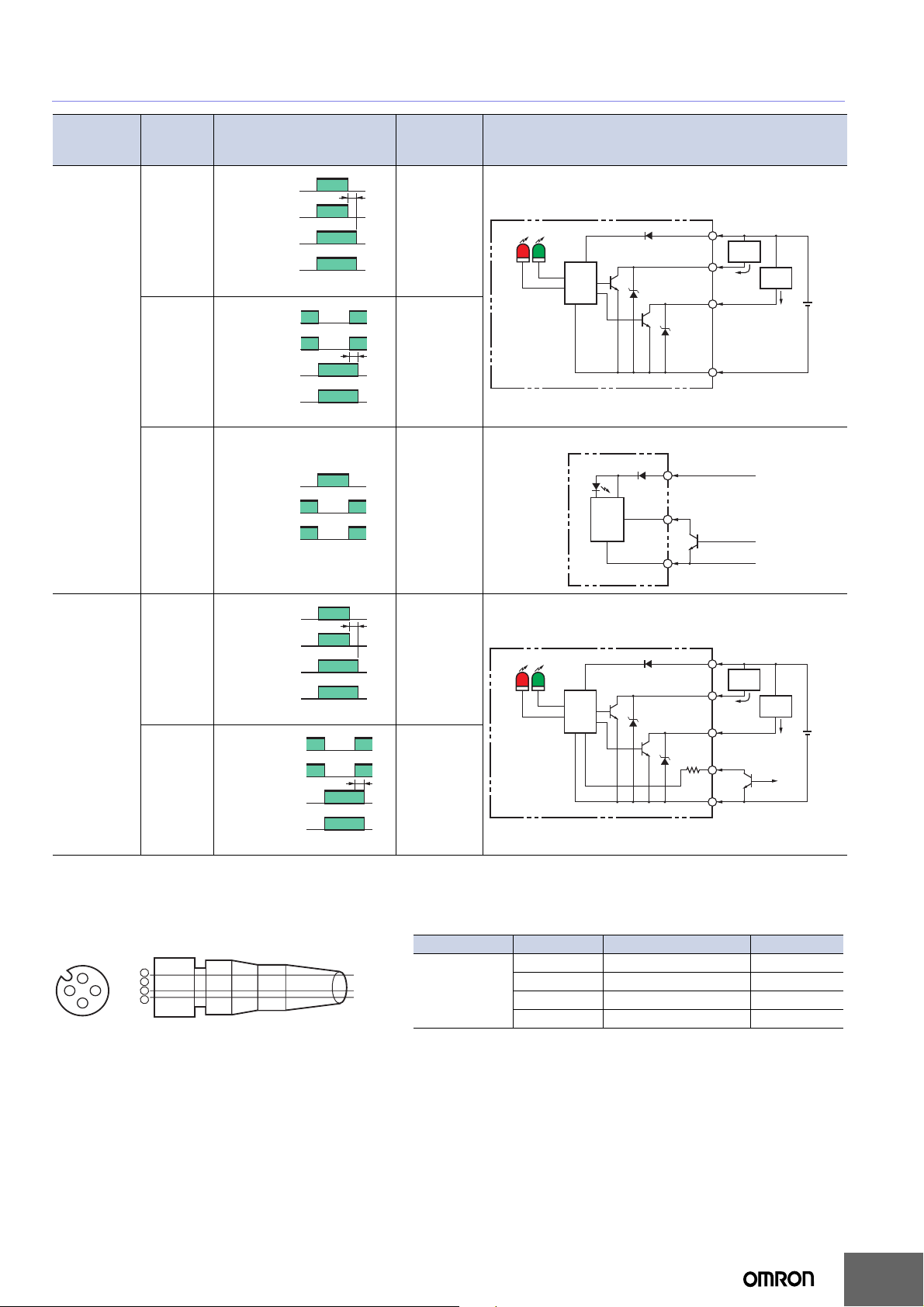
E3S-A
Model
E3S-AT21 *
E3S-AT71 *
E3S-AD21
E3S-AD71
E3S-AD22
E3S-AD72
E3S-AD23
E3S-AD73
Operation
mode
Light-ON
Dark-ON
--- ---
Timing charts
Incident light
No incident light
Light indicator
(red)
Output
transistor
Load
(e.g., relay)
T: OFF-delay timer (0 to 100 ms)
No incident light
Light indicator
(red)
Output
transistor
Load
(e.g., relay)
T: OFF-delay timer (0 to 100 ms)
External
diagnostic
input
Emitter LED
ON
OFF
ON
OFF
Operate
Reset
(Between brown and black)
Incident light
ON
OFF
ON
OFF
Operate
Reset
(Between brown and black)
ON
OFF
ON
OFF
ON
Indicator
(red)
OFF
(Between blue and pink)
T
T
Mode
selector
switch
L Side
(LIGHT ON)
D Side
(DARK ON)
Output circuit
Through-beam Receivers, Diffuse-reflective Sensors
Z
D
Brown
Pink
Blue
Brown
Black
Orange
Blue
10 to 30 VDC
(External
diagnostic input)
Light
indicator
(red)
Stability
indicator
(green)
Photoelectric
Sensor
main
circuit
Through-beam Emitters
Power indicator
(red)
Photoelectric
Sensor
main
circuit
100 mA max.
Z
D
50 mA max.
Load
(relay)
(Control
output)
(Self-diagnostic
output)
0 V
Load
(relay)
10 to
30 VDC
E3S-AR21
E3S-AR71
Light-ON
Dark-ON
Incident light
No incident light
Light indicator
(red)
Output
transistor
Load
(e.g., relay)
T: OFF-delay timer (0 to 100 ms)
No incident light
Light indicator
(red)
Output
transistor
Load
(e.g., relay)
T: OFF-delay timer (0 to 100 ms)
ON
OFF
ON
OFF
Operate
Reset
(Between brown and black)
Incident light
ON
OFF
ON
OFF
Operate
Reset
(Between brown and black)
T
L Side
(LIGHT ON)
T
D Side
(DARK ON)
Retro-reflective Sensors
Light
indicator
(red)
Stability
indicator
(green)
Photoelectric
Sensor
main
circuit
100 mA max.
Z
D
50 mA max.
Brown
Load
(relay)
(Control
output)
(Self-diagnostic
output)
Load
(relay)
(External
diagnostic input)
10 to
30 VDC
Black
Orange
Z
D
Pink
12 K
Blue
*Models numbers for Through-beam Sensors (E3S-AT@1) are f or sets that include both the Emitter and Receiver.
The model number of the Emitter is expressed by adding "-L" to the set model number (example: E3S-AT21-L 2M), the model number of the Receiver, by adding "D" (example: E3S-AT21-D 2M). Refer to Ordering Information to confirm model numbers for Emitter and Receivers.
Structure of Sensor I/O Connector
Classification Wire color Connection Pin No. Application
Brown1 +V
For DC
--- 2 ---
Blue 3 0 V
Black 4 Output
Note: Pin No. 2 is not used.
2
1 3
4
Terminal No.
1
2
3
4
XS2F-D421-DC0-F
Brown
Blue
Black
7
 Loading...