

Page 1
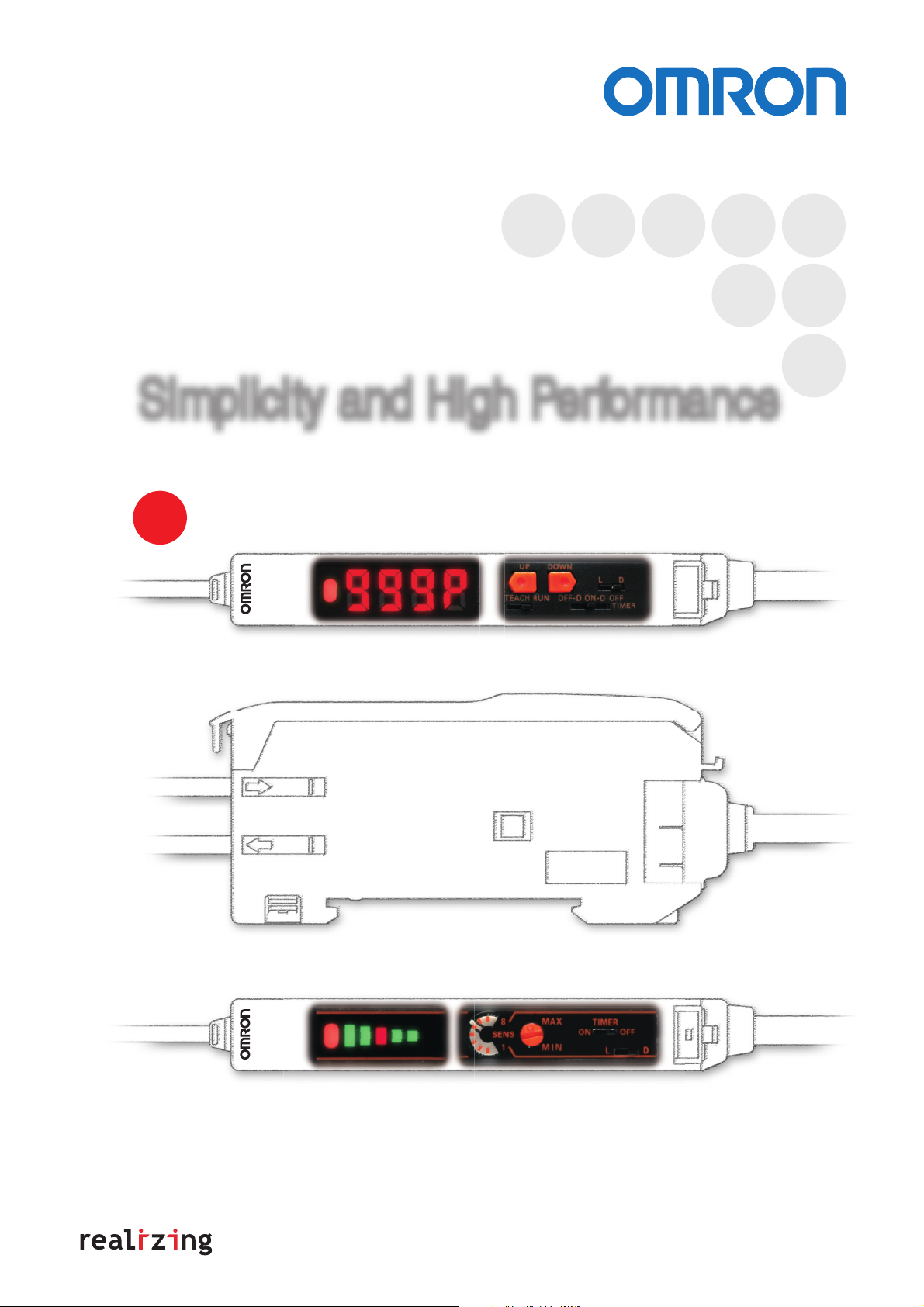
Simple Fiber Amplifiers
E3X-SD/NA Series
Simplicity and High Performance
The Series now includes models with digital displays and direct key setting.
NEW
Digital Display – Direct Key Setting
E3X-SD6
E3X-NA6
Bar Display – Manual Setting
Page 2

Simplicity and High Performance
Operation and Displays So Simple That Anyone Can Use the Amplifier Right Away
1
A design that focuses on simple operation has resulted in an Amplifier that is so simple it can be
operated without the manual.
The Amplifier also uses a large, easy-to-read operation indicator and a simple display for
excess gain (i.e., incident level/operating level).
Essentially anyone can use the Amplifier right away.
No screwdriver
Fine adjustments can be made in
increments of 1% using the Up
and Down Keys.
Compact No modes
Small body with width of 10 mm and
simple operation.
Compact size with length of 65 mm.
No manual
Setting is completed with a
single press when teaching
with/without the workpiece.
E3X-SD
E3X-NA
A timer function is provided as a standard feature.
The switch is for the timer only,
so no complicated operation is required.
10 mm
Fine tuning can be
performed using the
8-turn adjuster
(with indicator).
2
Immediately determine
operation and amount
mm
of light with a simple,
bright display.
With the E3X-SD, settings and
management can be
performed reliably using the
digital display ranging from 0%
to 999% (10 times), and with
the E3X-NA, the same can be
performed intuitively using the
large 5-level bar display.
999%
Large, easy-to-read
operation indicator
Stable light
interruption
· · ·
120%
110%
100%
90%
80%
Largest display
in the industry
Stable incident light
Intuitive display
Operating level
· · ·
0%
Large bar display with five levels:
80%, 90%, 100%, 110%, and 120%
for excess gain
(i.e., incident level/operating level)
6
Wire-saving Connector to Reduce Work and Stock Management
Gang-mount up to 16 Amplifiers.
• Large reduction in wiring work
• Simple management:
No distinction between master
and slaves
Master Connector
Power is supplied through
the connector, so
wire for output
for expansion.
only one
is required
Power supply pin
Slave Connector
Slide
Work efficiency is
also improved during
maintenance.
Page 3
Simplicity and High Performance
General-purpose Performance for Simple Use
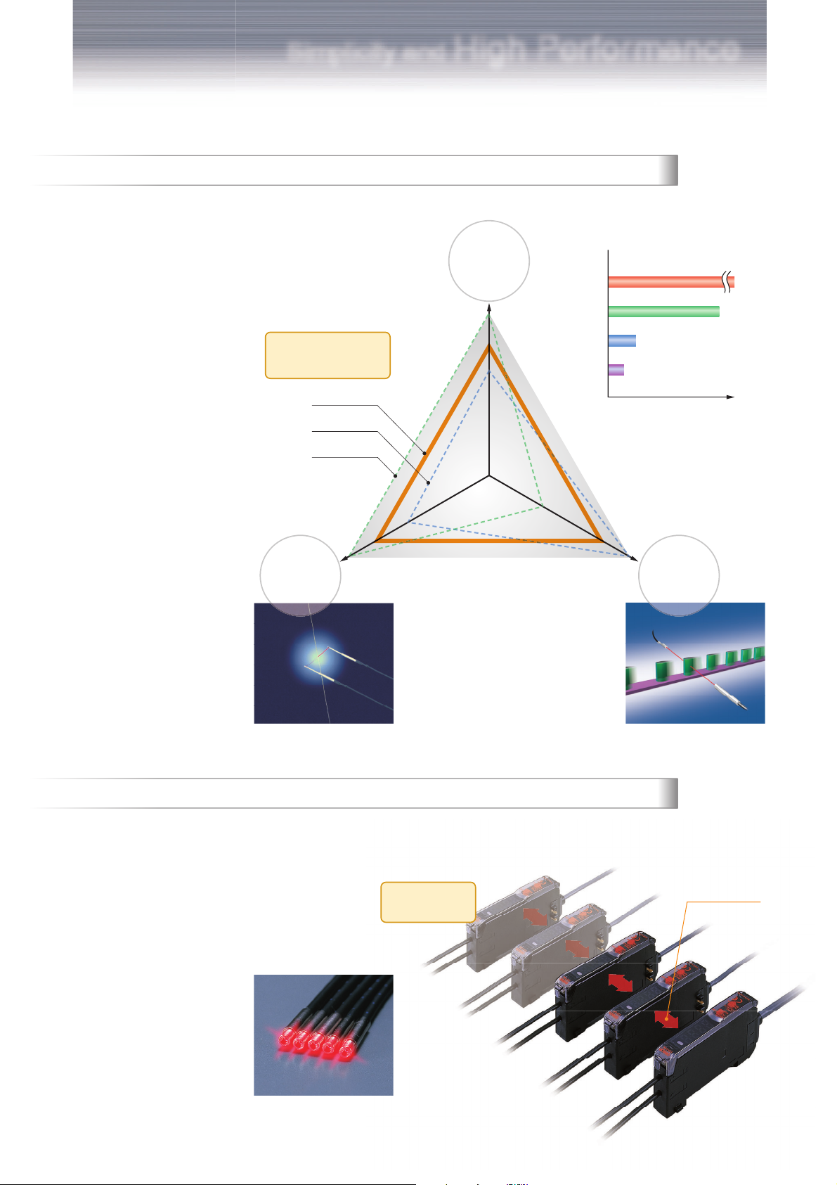
3
The three most important performance
capabilities when selecting a sensor are
achieved to a high standard: distance, speed,
and precision.
A balance is provided between reliable
detection performance and capability for a
broad range of applications.
Balanced
application capabilities
E3X-SD
High-speed Models
Long-distance Models
Precision
Distance
Super-long-distance
Standard Fiber Unit +
Long-distance Lens
E32-TC200+E39-F1
Long-distance Fiber Unit
Standard Fiber Unit
Fiber Unit
E32-T17L
E32-T11L
E32-TC200
3 m
700 mm
400 mm
Sufficient distance performance.
A maximum distance of 14 m
can be achieved by using a
Long-distance Fiber Unit
(through-beam) in combination
with the Amplifier.
Speed
14 m
Distance
4
30-µm dia.
Gold wire with a diameter of 30 µm can
be detected.
And minute workpieces can be detected.
Note: The diameter of 30 µm is a typical value
when the sensing distance and sensitivity are
set to their optimal conditions.
The response speed handles 2,500
counts per second to enable detecting
high-speed workpieces
(25,000 counts per second for the E3X-NA@F).
2,500 counts/second
200 µs
Optical Communications to Prevent Mutual Interference for Up to Five Amplifiers
Optical communications is used between Amplifiers.
Interference is reliably prevented for up to five Amplifiers by mutually staggering the light emission timing
(except for the E3X-NA@F).
Up to
five Amplifiers
Optical communications
High-speed response of 200 µm
and reliable interference
prevention for up to five Amplifiers
Page 4

Selecting Fiber Amplifiers
Simple
NEW
Standard
Amplifiers
Fastest in class
Super-high-speed
Amplifiers
(20 µs)
Water-resistant
Amplifiers
(IP66)
Reliable
E3X-SD@
For simple operation: Select a Simple Fiber Amplifier.
Digital display and direct setting
Intuitive
E3X-NA@
E3X-NA@F
E3X-NA@V
Bar display and adjuster setting
All in One
Standard
Amplifiers
Advanced
Amplifiers
Two-channel
Amplifiers
For multifunctional capability: Select an Advanced Fiber Amplifier.
E3X-DA@-S
Standard models
E3X-DA@AN-S
Easy measurement control using analog output
E3X-DA@TW-S
Range determination using twin outputs
E3X-DA@RM-S
Sensor control using external signal
E3X-DA@AT-S
World’s first
Reliable operation in dust using
automatic threshold control.
E3X-MDA@
New concept
Save space with two Amplifiers packed
into a single case.
Color-sensing
Amplifiers
NEW
E3X-DAC@-S
Color sensing models with white LEDs
World’s first
Stable detection with resistance against workpiece
movement.
Page 5

Simple Fiber Amplifier
E3X-SD/-NA
The Standard for Fiber Amplifiers
with Simple Operation and High
Performance
■ Operation so simple that essentially anyone can
use the amplifier right way.
■ Immediately determine operation and amount of
light with a simple, bright display.
■ General-purpose capabilities to simply handle a
broad range of applications.
Ordering Information
Amplifier Units
Digital Display and Direct Key Setting
Item Appearance
Standard models
Connection
method
Ratings and
Specifications
Model
NPN output PNP output
Bar Display and Adjuster Setting
Item Appearance
Standard models
High-speed
detection models
Pre-wired
---
Wire-saving
connector
Connection
method
Pre-wired
Wire-saving
connector
Pre-wired Response time: 20 µs E3X-NA11F E3X-NA41F
Ratings and
Specifications
---
E3X-SD11 E3X-SD41
E3X-SD6 E3X-SD8
Model
NPN output PNP output
E3X-NA11 E3X-NA41
E3X-NA6 E3X-NA8
Water-resistant
models
Pre-wired
Degree of protection:
IP66
Connector (M8) E3X-NA14V E3X-NA44V
E3X-NA11V E3X-NA41V
5
Page 6

E3X-SD/-NA
Amplifier Unit Connectors (Order Separately) Note: Stickers for Connectors are included as accessories.
Item Appearance Cable length No. of conductors Model
Master Connector
2 m
Slave Connector 1 E3X-CN12
Combining Amplifier Units and
Connectors
(Basically, Amplifier Units and Connectors are sold
separately)
Refer to the following tables when placing an order.
Type NPN PNP
Standard
models
When Using 5 Amplifier Units
Amplifier Units Applicable Connectors (Order Separately)
E3X-SD6 E3X-SD8 E3X-CN11 (3-wire) E3X-CN12 (1-wire)
E3X-NA6 E3X-NA8
5 Amplifier Units
3 E3X-CN11
+
Master Connector Slave Connector
+
1 Master Connector + 4 Slave Connectors
Sensor I/O Connectors (Order Separately)
Size Cable specifications Appearance Cable type Model
XS3F-M421-402-A
M8 Standard cable
Straight
connector
L-shaped
connector
2 m
Four-
5 m XS3F-M421-405-A
conductor
2 m XS3F-M422-402-A
cable
5 m XS3F-M422-405-A
Accessories (Order Separately)
Mounting Brackets
Appearance Applicable models Model Quantity
E3X-SD@
E3X-NA@
E3X-NA@F
E3X-NA@V E39-L148
E39-L143
1
End Plate
Appearance Model Quantity
PFP-M 1
6
Page 7
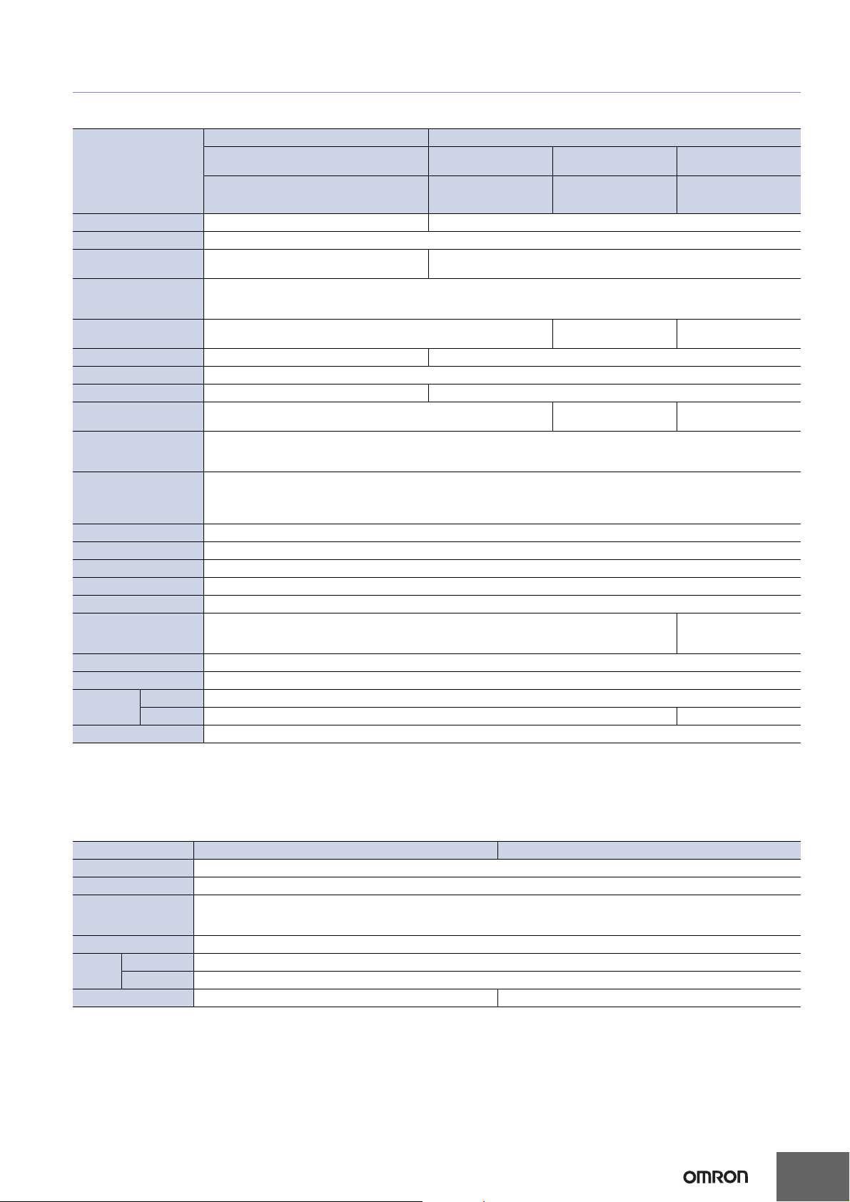
Ratings and Specifications
Amplifier Units
Digital display and direct key setting Bar display and adjuster setting
Type
Standard models Standard models
High-speed detection
models
E3X-SD/-NA
Water-resistant models
Item
Light source (wavelength) Red LED (620 nm) Red LED (680 nm)
Power supply voltage 12 to 24 VDC ±10%, ripple (p-p): 10% max.
Current consumption
Control output
Response time Operate or reset: 200 µs max. (*2)
Sensitivity adjustment UP/DOWN direct key setting, teaching 8-turn sensitivity adjuster (with indicator)
Protection circuits Power supply reverse polarity protection, output short-circuit protection, output reverse polarity protection (*3)
Timer function ON/OFF-delay timer: 10 ms (each fixed) OFF-delay timer: 40 ms (fixed)
Mutual interference
prevention
Ambient illumination
Ambient temperature
range
Ambient humidity range Operating and storage: 35% to 85% (with no condensation)
Insulation resistance 20 MΩ. min. (at 500 VDC)
Dielectric strength 1,000 VAC at 50/60 Hz for 1 minute (*4)
Vibration resistance Destruction: 10 to 55 Hz with a 1.5-mm double amplitude for 2 hrs each in X, Y and Z directions
Shock resistance Destruction: 500 m/s2, for 3 times each in X, Y and Z directions
Degree of protection IEC 60529 IP50 (with Protective Cover attached)
Connection method Pre-wired (standard cable length: 2 m), or connector
Weight (packed state) Pre-wired model: Approx. 100 g, Model with connector: Approx. 55 g (*5)
Material
Accessories Instruction manual
*1. For the E3X-NA, residual voltage is 1 V max.
*2. When there are 8 or more E3X-NA Amplifiers mounted side-by-side, the response time will be 350 µs max.
*3. The E3X-NA does not have output reverse polarity prevention.
*4. Water-resistant models and models with connectors have a dielectric strength of 500 VAC.
*5. Add 10 g for water-resistant models.
Model E3X-SD@ E3X-NA@ E3X-NA@F E3X-NA@V
960 mW max. (Power supply: 24 V,
Current consumption: 40 mA max.)
Open-collector output (NPN or PNP)
Load power supply: 26.4 V max., Load current: 50 mA max. (Residual voltage: 1.5 V max.) (*1)
Light-ON/Dark-ON mode selector
Up to 5 Amplifiers (optically synchronized) None
Receiver side
Incandescent lamp: 10,000 lux max.
Sunlight: 20,000 lux max.
Operating: Groups of 1 to 3 Amplifiers: −25°C to 55°C
Storage: −30°C to 70°C (with no icing or condensation)
Case Polybutylene terephthalate (PBT)
Cover Polycarbonate Polyethersulfone (PES)
Groups of 4 to 11 Amplifiers: −25°C to 50°C
Groups of 12 to 16 Amplifiers: −25°C to 45°C
35 mA max.
Operate: 20 µs max.
Reset: 30 µs max.
Operate or reset: 200 µs
max. (*2)
Up to 5 Amplifiers (optically synchronized)
IEC 60529 IP66
(with Protective Cover attached)
Amplifier Unit Connectors
Item Model E3X-CN11 E3X-CN12
Rated current 2.5 A
Rated voltage 50 V
Contact resistance
Number of insertions Destruction: 50 times (for connection to the Amplifier Unit and the adjacent Connector)
Material
Weight (packed state) Approx. 55 g Approx. 25 g
Housing Polybutylene terephthalate (PBT)
Contact Phosphor bronze/gold-plated nickel
20 mΩ max. (20 mVDC max., 100 mA max.)
(The above figure is for connection to the Amplifier Unit and the adjacent Connector. It does not include the conductor resistance of the
cable.)
7
Page 8
E3X-SD/-NA
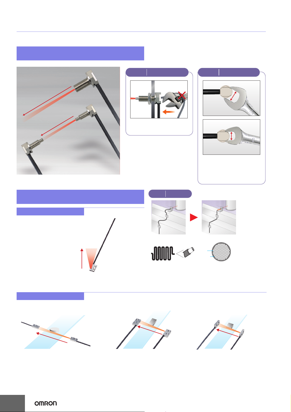
Fiber Unit Overview
No snagging, no breaking:
Right-angle (L-shaped) Models
Feature
90 mm
280 mm
Reflective model,
M6 screw
E32-D11N
Through-beam model,
M4 screw
E32-T11N
No snagging during maintenance.
Fiber flexibility prevents breaking.
Flat and flexible fiber models are easy to mount
and will not break.
Reflective Fiber Units
Flat View
E32-D15ZR
L-shaped Attachment
1
Feature
No Breaking
Feature
10 mm*
8 mm*
Convenient design
accommodates two wrench sizes.
Allows quick tightening.
*For M6 models.
New Head Shape
2
20 mm
Size: 15 × 10 × 3 mm
Through-beam Fiber Units
Top View
E32-T15XR
280 mm
Size: 15 × 8 × 3 mm
Side View
E32-T15YR
Flexible fiberConventional fiber
Cores
Cladding
A large number of ultrafine cores are all surrounded by cladding. As
a result, the fiber is flexible and can be bent without significantly
reducing the light intensity. This helps solve problems, such as
fiber being broken by getting caught on other objects.
Flat View
E32-T15ZR
110 mm
110 mm
8
Page 9
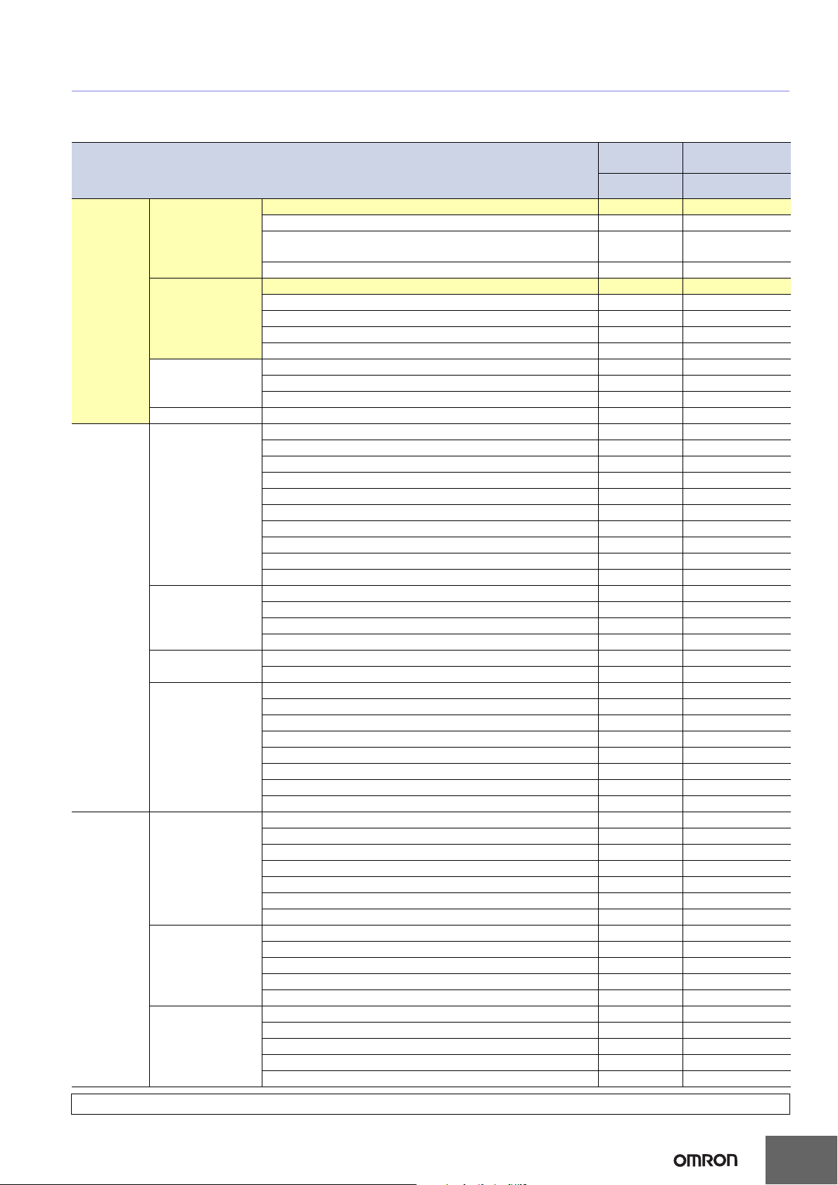
E3X-SD/-NA
Sensing Distance
Through-beam Models (Unit: mm)
E3X-SD@
E3X-NA@
Standard
models
60 18
High-speed detection
E3X-NA@F
models
Type
Standard
models
Special-
beam
models
Environment
resistive
models
Model
E32-T11R/E32-T12R/E32-T15XR/E32-TC200BR (B4R) 280 80
Flexible
(new standard)
Standard
Break resistant
Fluorine coating E32-T11U 360 100
Long distance,
high power
Ultracompact,
ultrafine sleeve
Fine beam
(narrow vision field)
Area sensing
Heat resistant
Chemical
resistant
Vacuum
resistant
E32-T14LR/E32-T15YR/E32-T15ZR 110 33
E32-T21R/E32-T22R/E32-T222R/E32-T25XR/
E32-TC200FR (F4R)
E32-T24R/E32-T25YR/E32-T25ZR 30 9
E32-TC200/E32-T12/E32-T15X/E32-TC200B (B4) 400 120
E32-T14L/E32-T15Y/E32-T15Z 240 70
E32-TC200A 360 100
E32-TC200E/E32-T22/E32-T222/E32-T25X/E32-TC200F (F4) 100 30
E32-T24/E32-T25Y/E32-T25Z 90 27
E32-T11/E32-T12B/E32-T15XB 360 100
E32-T21/E32-T221B/E32-T22B 100 30
E32-T25XB 75 20
E32-T17L 14000 4200
E32-TC200 + E39-F1 3000 900
E32-T11R + E39-F1 2100 630
E32-T11 + E39-F1 2000 600
E32-T14 1800 540
E32-T11L/E32-T12L 700 210
E32-T11L + E39-F2 500 150
E32-T11R + E39-F2 220 65
E32-T11 + E39-F2 360 100
E32-T21L/E32-T22L 200 60
E32-T223R 60 18
E32-T33-S5 20 6
E32-T333-S5 5 1.5
E32-T334-S5 2.5 0.8
E32-T22S 1000 300
E32-T24S 700 210
E32-T16PR 450 130
E32-T16P 600 180
E32-T16JR 390 110
E32-T16J 520 150
E32-T16WR 690 200
E32-T16W 920 270
E32-T16 1500 450
E32-M21 300 90
E32-T51 400 120
E32-T54 130 35
E32-T81R-S 180 50
E32-T61-S + E39-F2 390 130
E32-T61-S + E39-F1 3000 900
E32-T84S-S 700 210
E32-T61-S 300 90
E32-T11F 1050 380
E32-T12F 1600 480
E32-T14F 200 60
E32-T51F 700 200
E32-T81F-S 350 100
E32-T51V 100 --E32-T51V + E39-F1V 600 --E32-T54V 65 --E32-T54V + E39-F1V 390 --E32-T84SV 250 ---
For information on Fiber Units, refer to the E32 Series Fiber Sensor Best Selection (Cat. No. E354).
9
Page 10
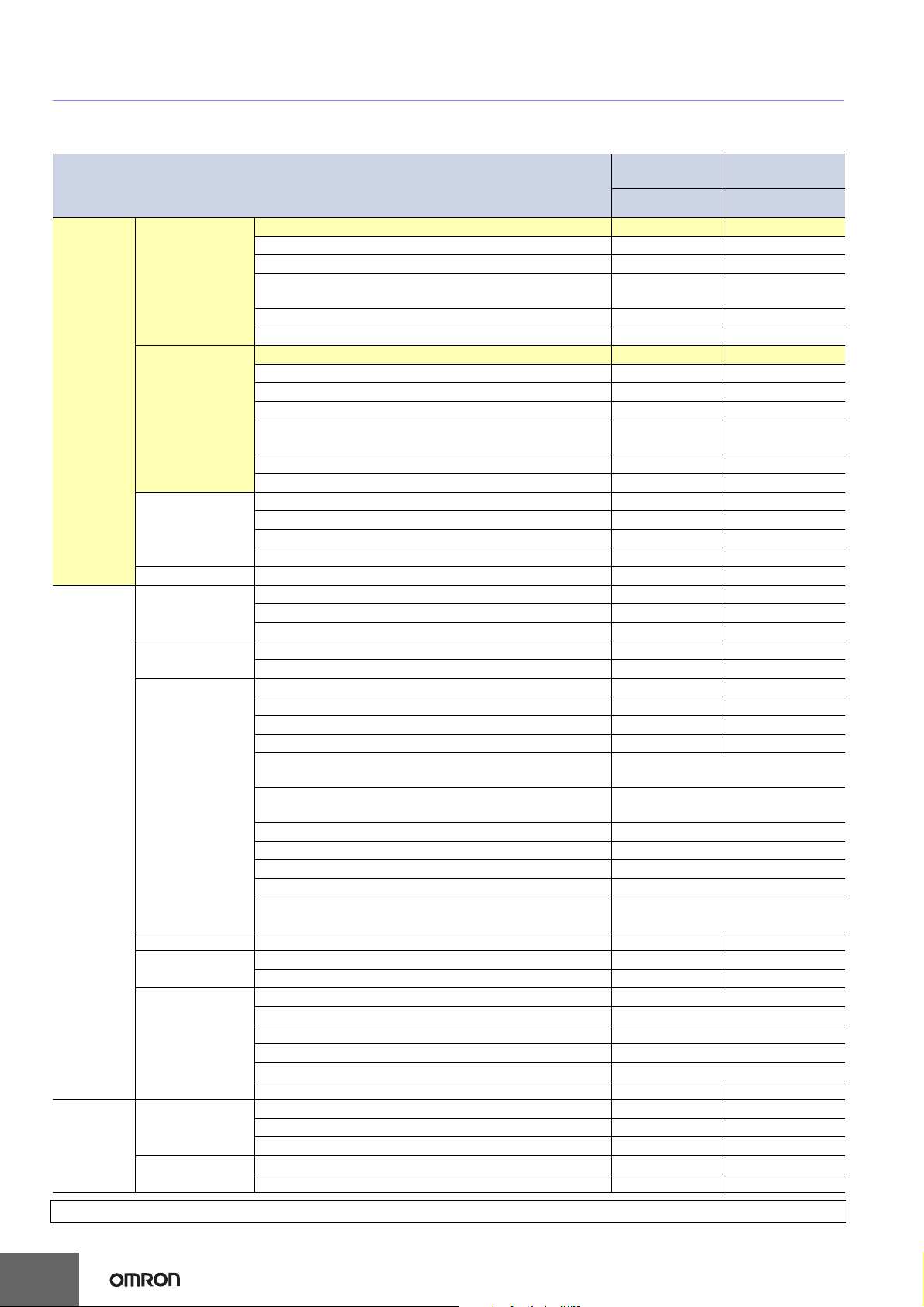
E3X-SD/-NA
Reflective Models (Unit: mm)
E3X-SD@
E3X-NA@
Standard
models
15 5
36 12
Spot diameter of 0.1 to 0.6 mm at
6 to 15 mm.
Spot diameter of 0.5 to 1 mm at
6 to 15 mm.
Spot diameter of 4 mm max. at
0 to 20 mm.
E3X-NA@F
High-speed detection
models
Type
Standard
models
Special-
beam
models
Environ-
ment
resistive
models
Model
E32-D11R/E32-D12R/E32-D15XR/E32-DC200BR (B4R) 90 30
E32-D14LR 16 5
Flexible
(new standard)
Standard
Break resistant
Fluorine coating E32-D11U 90 30
Long distance,
high power
Ultracompact,
ultrafine sleeve
Coaxial, small spot
Area sensing E32-D36P1 75 25
Retro-reflective
Convergent-
reflective
Heat resistant
Chemical resistant
E32-D15YR/E32-D15ZR 20 5
E32-D211R/E32-D21R/E32-D22R/E32-D25XR/
E32-DC200FR (F4R)
E32-D24R 7 2.3
E32-D25YR/E32-D25ZR 4 1.2
E32-DC200/E32-D15X/E32-DC200B (B4) 150 50
E32-D12 120 40
E32-D14L 40 13
E32-D15Y/E32-D15Z 50 15
E32-D211/E32-DC200E/E32-D22/E32-D25X/
E32-DC200F (F4)
E32-D24 15 5
E32-D25Y/E32-D25Z 10 3.3
E32-D11/E32-D15XB 90 30
E32-D21B/E32-D221B 35 10
E32-D21/E32-D22B 15 5
E32-D25XB 25 8
E32-D16 40 to 400 55 to 70
E32-D11L 200 65
E32-D21L/E32-D22L 50 17
E32-D33 10 3.3
E32-D331 1.5 0.5
E32-CC200R 75 25
E32-CC200 150 50
E32-D32L 80 25
E32-C31/E32-D32 40 13
E32-C42 + E39-F3A
E32-D32 + E39-F3A
E32-C41 + E39-F3A-5 Spot diameter of 0.1 mm at 7 mm.
E32-C31 + E39-F3A-5 Spot diameter of 0.5 mm at 7 mm.
E32-C41 + E39-F3B Spot diameter of 0.2 mm at 17 mm.
E32-C31 + E39-F3B Spot diameter of 0.5 mm at 17 mm.
E32-C31 + E39-F3C
E32-R21 + E39-R3 (provided) 10 to 250
E32-R16 + E39-R1 (provided) 150 to 1500 150 to 1000
E32-L25/E32-L25A 3.3
E32-L24S 0 to 4
E32-L24L 2 to 6 (center 4)
E32-L25L 5.4 to 9 (center 7.2)
E32-L86 4 to 10
E32-L16 0 to 15 0 to 13
E32-D51 120 40
E32-D81R/E32-D61 45 15
E32-D73 30 10
E32-D12F 50 16
E32-D14F 20 6.5
10
For information on Fiber Units, refer to the E32 Series Fiber Sensor Best Selection (Cat. No. E354).
Page 11
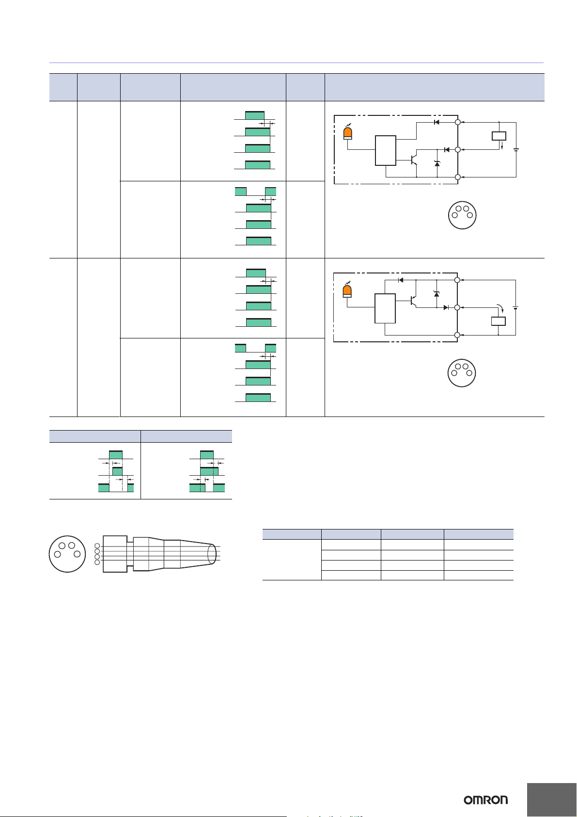
I/O Circuit Diagrams
E3X-SD/-NA
Output
form
NPN
Output
PNP
Output
Model
E3X-SD11
E3X-SD6
E3X-NA11
E3X-NA6
E3X-NA11F
E3X-NA11V
E3X-NA14V
E3X-SD41
E3X-SD8
E3X-NA41
E3X-NA8
E3X-NA41F
E3X-NA41V
E3X-NA44V
Output
transistor
operation mode
Light-ON
Dark-ON
Light-ON
Dark-ON
No incident light
Operation
indicator
(orange)
Output
transistor
Load
(relay)
(Between brown and black leads)
No incident light
Operation
indicator
(orange)
Output
transistor
Load
(relay)
(Between brown and black leads)
No incident light
Operation
indicator
(orange)
Output
transistor
Load
(relay)
No incident light
Operation
indicator
(orange)
Output
transistor
Load
(relay)
Note: Timing Charts for Timer Settings (T: Set Time)
ON delay OFF delay
Incident light
No incident light
L-ON
D-ON
ON
OFF
ON
OFF
T
T
Incident light
No incident light
L-ON
D-ON
ON
OFF
ON
OFF
Timing charts
Incident light
ON
ON
ON
ON
T
T
T
T
ON
OFF
ON
OFF
Operate
Reset
Incident light
ON
OFF
ON
OFF
Operate
Reset
Incident light
OFF
OFF
Operate
Reset
(Between blue and black leads)
Incident light
OFF
OFF
Operate
Reset
(Between blue and black leads)
T
T
Operation
selector
LIGHT ON
(L-ON)
DARK ON
(D-ON)
LIGHT ON
(L-ON)
DARK ON
(D-ON)
Output circuit
Operation indicator
(orange)
Photoelectric
Sensor
main
circuit
• M8 Connector Pin Arrangement
Note: Pin 2 is not used.
*Not present on the E3X-NA.
Operation
indicator
(orange)
Photoelectric
Sensor
main
circuit
• M8 Connector Pin Arrangement
Note: Pin 2 is not used.
Brown
1
Control output
4
3
Control output
4
3
Load
Load
Black
*
4
Blue
3
2
1
Brown
1
Black
*
4
Blue
3
2
1
*Not present on the E3X-NA.
12 to
24 VDC
12 to
24 VDC
Plug (Sensor I/O Connector)
Terminal number
2
4
3
1
2
1
3
4
XS3F-M421-402-A
XS3F-M421-405-A
XS3F-M422-402-A
XS3F-M422-405-A
Wire color
Brown
White
Blue
Black
Classification Wire color Connection pin Application
Brown 1 Power supply (+V)
DC
White 2 ---
Blue 3 Power supply (0 V)
Black 4 Output
Note: Pin 2 is not used.
11
Page 12
E3X-SD/-NA
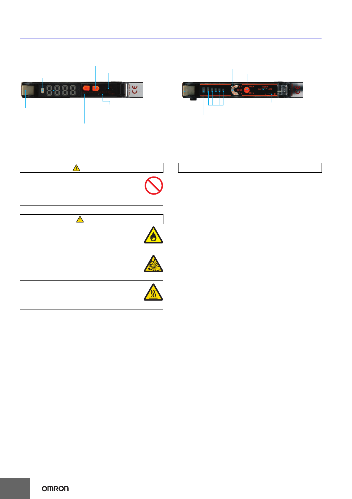
Nomenclature
Amplifier Units
E3X-SD@ E3X-NA
Operation Indicator
Operation Keys
Sensitivity adjustment
(UP/DOWN or teaching)
Operation Selector
Use to switch between
Light-ON and Dark-ON
Sensitivity indicator
8-turn sensitivity adjuster
Lock lever
Incident level
indicators
TEACH/RUN Mode Selector
Used to select TEACH or RUN mode.
Timer switch
OFF/D: OFF-delay timer
ON/D: ON-delay timer
OFF: Timer function is OFF.
Safety Precautions
WARNING
This product is not designed or rated for
ensuring safety of persons either directly or
indirectly.
Do not use it for such purposes.
Caution
Do not exceed the rated voltage.
Excess voltage may result in malfunction or
fire.
Do not use an AC power supply.
Using an AC power supply may result in
rupturing.
High-temperature environments may result in
burn injury.
Operation Selector
Lock lever
Incident level indicators
Operation Indicator
Use to switch between
Light-ON and Dark-ON
Timer switch
ON: Timer function is ON.
OFF: Timer function is OFF.
Precautions for Safe Use
The following precautions must be observed to ensure safety.
1. Do not use the product in locations where flammable or
explosive gas is present.
2. Do not use the product in locations subject to splashing
water, oil, or chemicals, or in locations subject to steam.
3. Do not attempt to disassemble, repair, or modify the
product.
4. Do not apply voltage or current in excess of the rated
ranges.
5. Do not use the product in atmospheres or environments
that exceed product ratings.
6. Do not wire the product incorrectly, such as using incorrect
power supply polarity.
7. Connect the load properly.
8. Do not short-circuit both ends of the load.
9. Do not use the product if the case is damaged.
10. When disposing of the product, dispose of it as industrial
waste.
11. Do not use the product in locations subject to direct
sunlight.
12. The surface temperature of the product may rise as a
result of the ambient temperature, power supply, or other
usage conditions. Use caution when performing
maintenance and washing. Failure to do so may result in
burn injury.
12
Page 13
Precautions for Correct Use
Do not use the product in atmospheres or environments that
exceed product ratings.
Amplifier Units
● Designing
Communications Hole
The hole on the side of the Amplifier Unit is a communications
hole for preventing mutual interference when Amplifier Units
are mounted side-by-side. The E3X-MC11 Mobile Console
(order separately) cannot be used.
If an excessive amount of light is received via the Sensor, the
mutual interference prevention function may not work. In this
case, make the appropriate adjustments using the sensitivity
adjuster.
The mutual interference prevention function will not operate
when the E3X-SD/NA is used side-by-side with E3X-DA-N
models.
● Mounting
DIN Track Mounting/Removal
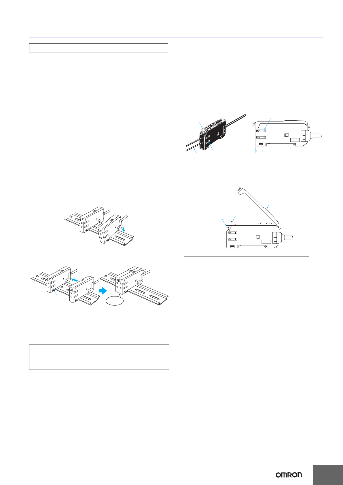
Mounting Amplifier Units
1. Mount the Amplifier Units one at a time onto the DIN track.
E3X-SD/-NA
Fiber Connection and Disconnection
The E3X Amplifier Unit has a lock lever. Connect or
disconnect the fibers to or from the E3X Amplifier Unit using
the following procedures:
1. Connection
Open the Protective Cover, insert the fibers according to the
fiber insertion marks on the side of the Amplifier Unit, and
lower the lock lever.
Lock lever
Fiber insertion mark
Fiber
2. Disconnection
Remove the Protective Cover and raise the lock lever to pull
out the fiber.
Insertion position
10.7 mm
Protective Cover
2. Slide the Amplifier Units together, line up the clips, and
press the Amplifier Units together until they click into place.
Clip
Click into
place
Removing Amplifier Units
Slide Amplifier Units away from each other, and remove from
the DIN track one at a time. (Do not attempt to remove
Amplifier Units from the DIN track without separating them
first.)
Note 1. The specifications for ambient temperature will vary according to the
number of Amplifier Units used together. For details, refer to Ratings
and Specifications.
2. Always turn OFF the power supply before mounting or removing
Amplifier Units.
Locked
Note:To maintain the fiber properties, confirm that the lock is
released before removing the fiber.
Unlocked
3. Precautions for Fiber Connection/Disconnection
Be sure to lock or unlock the lock lever within an ambient
temperature range between −10°C and 40°C.
● Operating Environment
Ambient Conditions
If dust or dirt adhere to the hole for optical communications, it
may prevent normal communications. Be sure to remove any
dust or dirt before using the Units.
● Other
Protective Cover
Be sure to mount the Protective Cover before use.
13
Page 14
E3X-SD/-NA
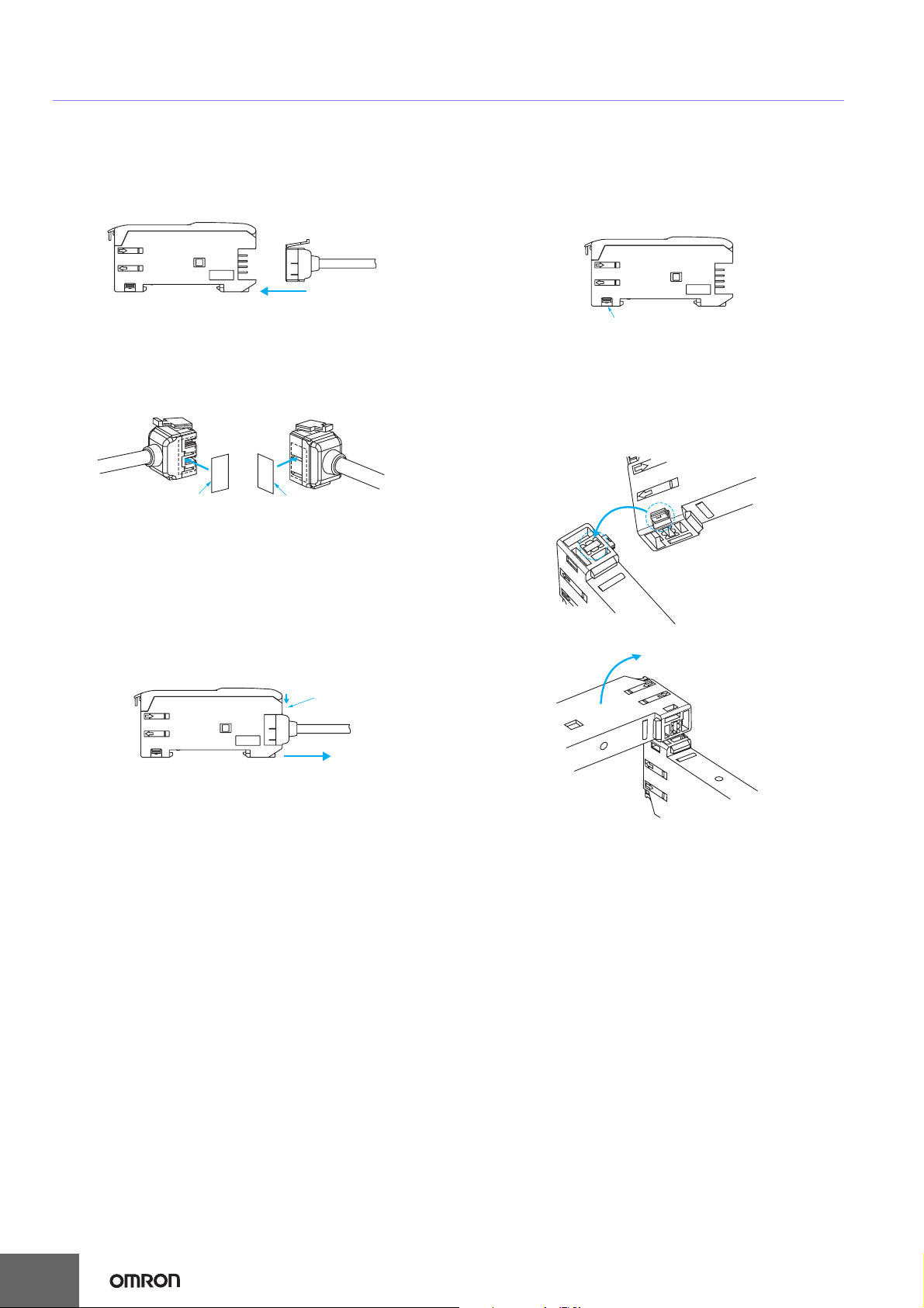
Amplifier Units with Connectors
● Mounting
Mounting Connectors
1. Insert the Master or Slave Connector into the Amplifier Unit
until it clicks into place.
Insert
2. Join Amplifier Units together as required after all the Master
and Slave Connectors have been inserted.
3. Attach the stickers (provided as accessories) to the sides of
Master and Slave Connectors that are not connected to
other Connectors.
Mounting End Plate (PFP-M)
Depending on how it is mounted, an Amplifier Unit may move
during operation. In this case, use an End Plate.
Before mounting an End Plate, remove the clip from the
master Amplifier Unit using a nipper or similar tool.
Clip
The clip can also be removed using the following mechanism,
which is incorporated in the construction of the section
underneath the clip.
1. Insert the clip to be removed into the slit underneath the clip
on another Amplifier Unit.
Sticker
Note: Attach the stickers to the sides with grooves.
Sticker
Removing Connectors
1. Slide the slave Amplifier Unit for which the Connector is to
be removed away from the rest of the group.
2. After the Amplifier Unit has been separated, press down on
the lever on the Connector and remove it. (Do not attempt
to remove Connectors without separating them from other
Amplifier Units first.)
Press down
Lever
Remove
2. Remove the clip by rotating the Amplifier Unit.
Rotate
Pull Strengths for Connectors (Including Cables)
E3X-CN11: 30 N max.
E3X-CN12: 12 N max.
14
Page 15
E3X-SD/-NA
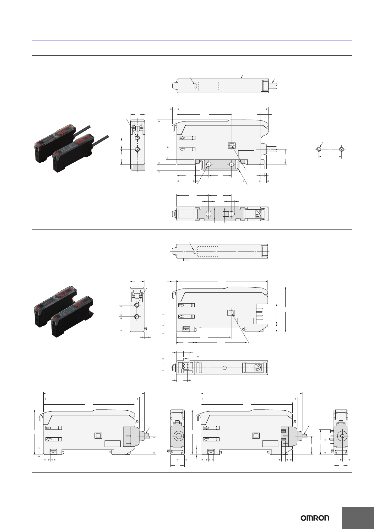
Dimensions (Unit: mm)
Amplifier Units
Amplifier Units with Cables
E3X-SD11
E3X-SD41
E3X-NA11
E3X-NA11F
E3X-NA41
E3X-NA41F
Amplifier Units with Connectors
E3X-SD6
E3X-SD8
E3X-NA6
E3X-NA8
Two ,
2.4 dia.
8
10.7
With Mounting Bracket Attached
Operation indicator
3
10
31.5
9.9
4.1
22.4
13
Two, 3.2-dia. holes
22.4
Operation indicator
64.3
38.6
16
34.8
16
3.4
4.4
A *1
4.4
3.4
4-dia. vinyl-insulated round cable with
3 conductors* (Conductor cross section: 0.2 mm
Insulator diameter: 1.1 mm),
Standard length: 2 m.
5.3
Mounting Holes
Two, M3
10.75
Hole for optical communications *2
Mounting bracket (E39-L143) (Order separately)
Stainless steel (SUS304)
2.4
4
*1. The mounting bracket can also be used on
side A.
*2. There is no hole for E3X-NA@F models.
2
;
16
8
10.7
Dimensions with Master Connector Connected
71
67.5
64.3
31.5
1.5
1.8
5.1 3.9
10
Two, 2.4 dia.
1.8
E3X-CN11:
4.0 dia.
12.95
64.33
31.5
9.9
3.4
38.6
13
3.95.1
1.7
4.2
1.8
6.2
1.7
36.7
Hole for optical communications
(for preventing mutual interference)
14
5.5
Dimensions with Slave Connector Connected
71
67.5
64.3
E3X-CN12: 2.6 dia.
31.5
1.5
4
1.8
10
5.1 3.9
3
4.8
12.95
17.45
11.55
4
10
15
Page 16
E3X-SD/-NA
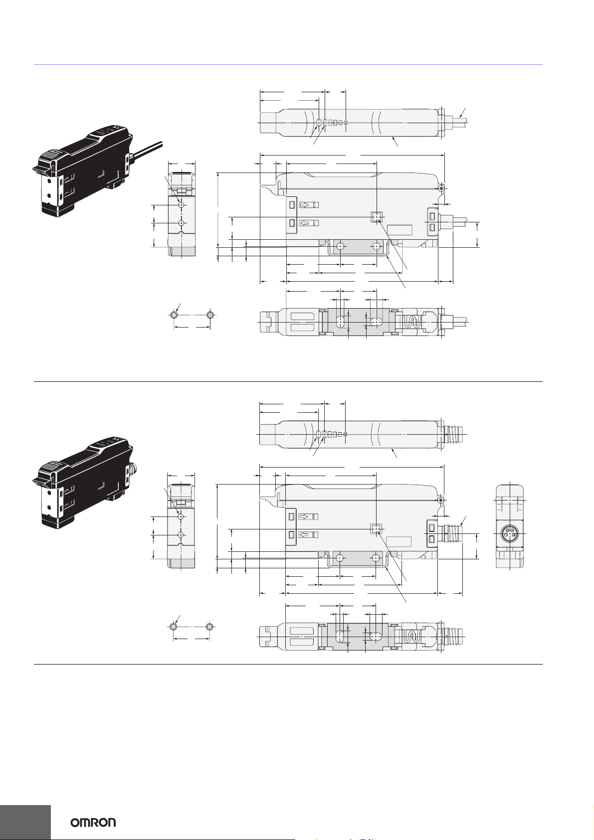
Amplifier Units with Cables,
Water-resistant Models
E3X-NA11V
E3X-NA41V
Two ,
2.4 dia.
8
10.7
12
Mounting Holes
Two, M3
16
With Mounting Bracket Attached
28.65
25.95
Operation indicator
6.9
33
9.9
3.43.9
4.3
14.4
11.5
9.2
Incident level indicators
23.9
23.9
81.5
40
3.4
5.4
*2
A *1
2.8
Hole for
16
37
67.2
16
3.4
*1. The mounting bracket can also be used on side A.
*2. 4-dia. vinyl-insulated round cable with 3 conductors
optical
communications
Mounting bracket (E39-L148) (Order separately)
Stainless steel (SUS304)
5.4
(Conductor cross section: 0.45 mm
1.1 mm), Standard length: 2 m.
6.6
11.2
2
, Insulator diameter:
Amplifier Units with Connectors,
Water-resistant Models
E3X-NA14V
* The mounting bracket can also be
used on this side A.
E3X-NA44V
Two ,
2.4 dia.
8
10.7
12
Mounting Holes
Two, M3
16
With Mounting Bracket Attached
28.65
25.95
Operation indicator
6.9
33
9.9
3.43.9
4.3
14.4
11.5
9.2
Incident level indicators
23.9
23.9
81.5
40
3.4
5.4
16
16
37
67.2
A*
M8
2.8
11.2
Hole for
optical
communications
Mounting bracket (E39-L148) (Order separately)
Stainless steel (SUS304)
5.4
3.4
11
16
Page 17
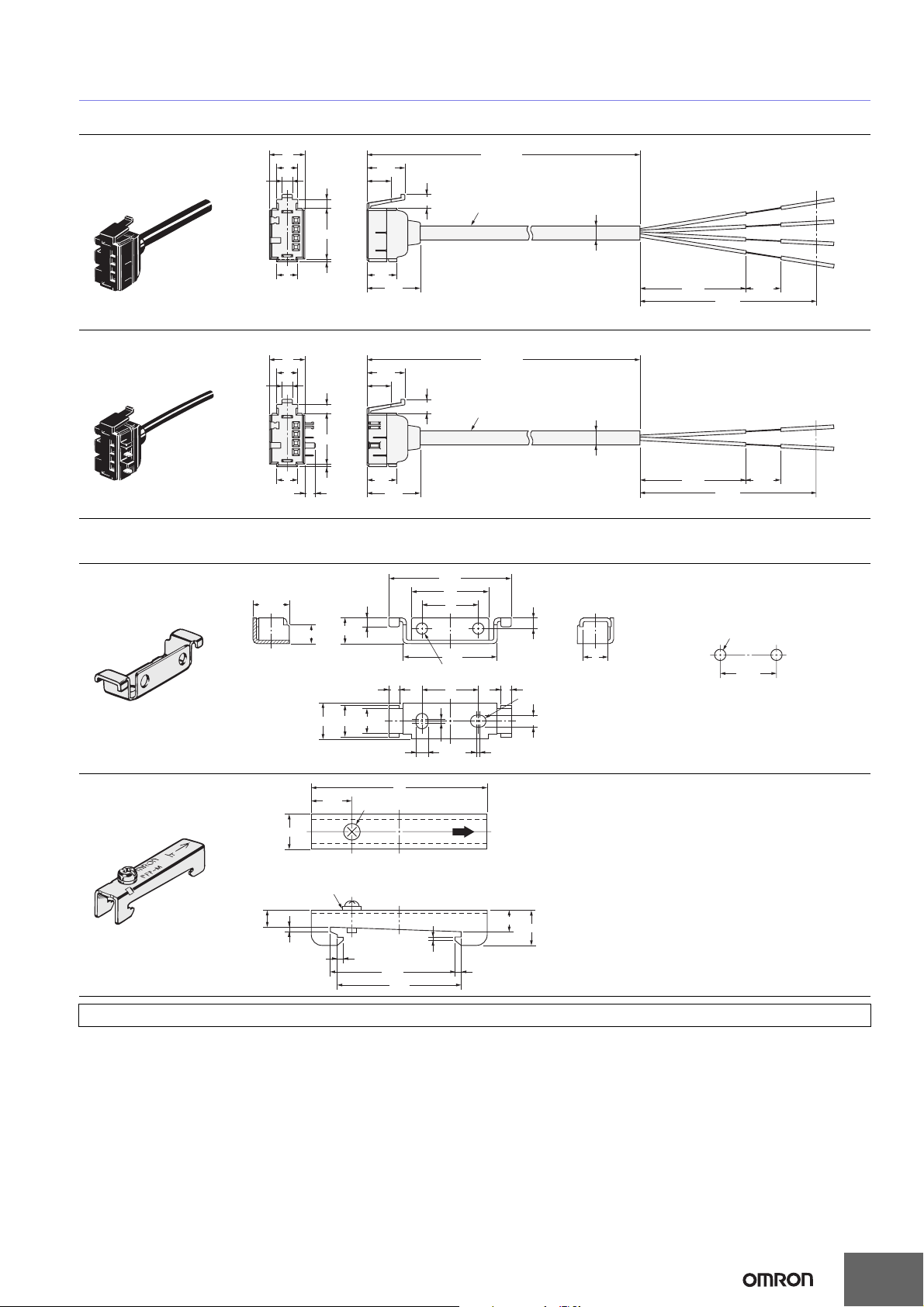
Amplifier Unit Connectors
Master Connector
E3X-CN11
2.9
E3X-SD/-NA
+50
10
6
2.6
14.4
6.8
10.7
4
2,000
*
0
4 dia.
6
*E3X-CN11: 2.6-dia. vinyl-insulated round cable with 3 conductors (Conductor cross section: 0.2 mm2, Insulator diameter: 1.1 mm)
Slave Connector
E3X-CN12
10
6
2.9
6
3
*E3X-CN12: 2.6-dia. vinyl-insulated round cable with 1 conductor (Conductor cross section: 0.2 mm2, Insulator diameter: 1.1 mm)
Accessories (Order Separately)
Mounting Brackets
E39-L143
Material: Stainless steel
(SUS304)
End Plates
PFP-M
(10.3)
5.3
0.8
2.6
14.4
0.8
10 max. 710.3
11.5
2.5
7.3
M4 × 8
panhead screw
6.8
8.4
10.7
8.4
15.1
15.1
30±2
+50
2,000
0
4
3.4
50
34.8
22
16
26.8
Two, 3.2 dia.
1
*
3163
1
E3X-CN12: 2.6 dia.
E3X-CN22: 4 dia.
3
Four, R1.7
3.4
30±2
7
10
±2
+5
50
0
10
±2
+5
50
0
Mounting Holes
Two , M 3
16
±0.1
10
M4 spring washer
4.8
1.3
1.8
1
35.5
35.3
6.2
10
1.8
For information on Fiber Units, refer to the E32 Series Fiber Sensor Best Selection (Cat. No. E354).
17
Page 18
E3X-SD/-NA
Operating Procedure
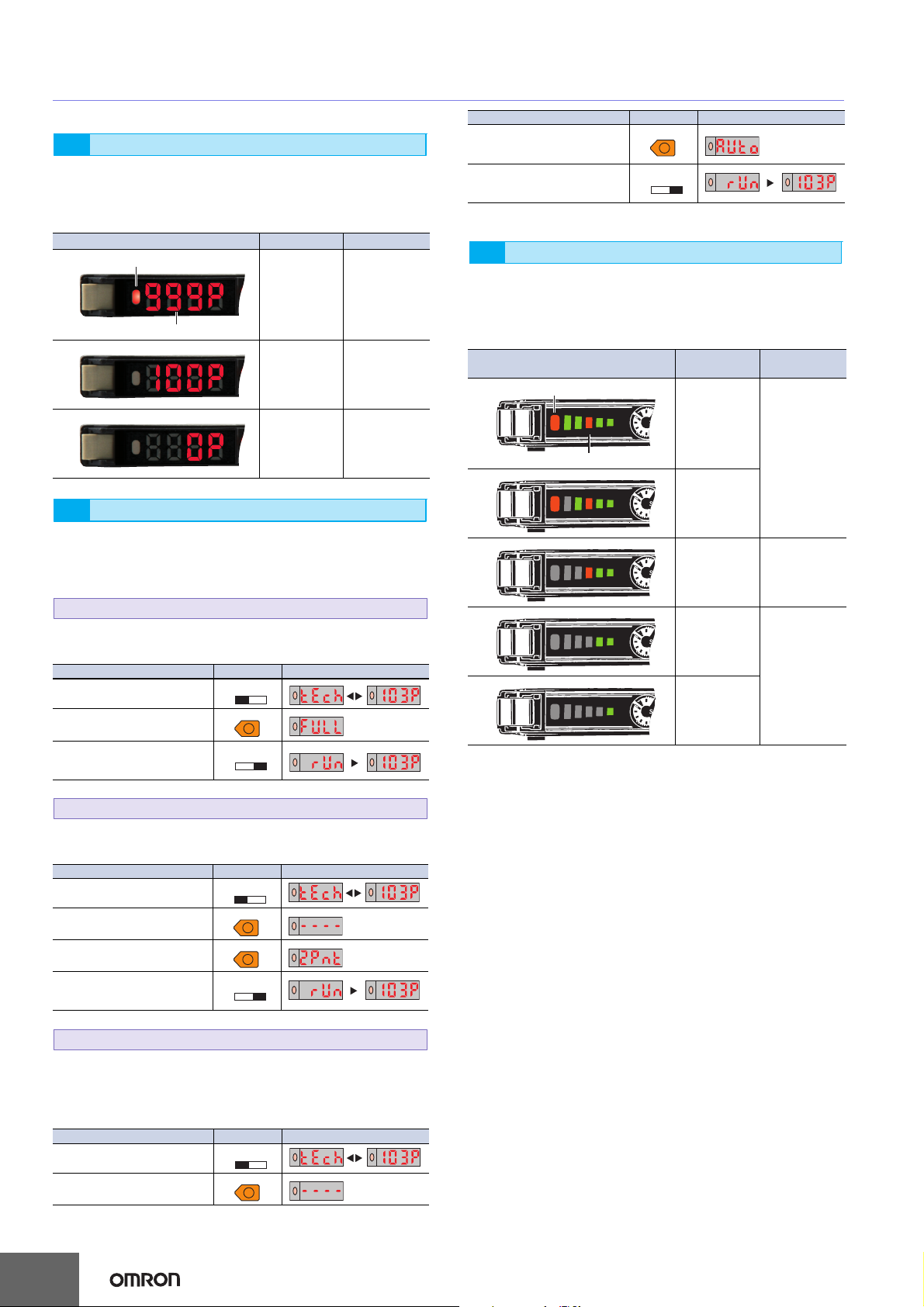
E3X-SD@
Displays1
A 7-segment display showing excess gain is provided in
addition to the orange operation indicator.
Use these when adjusting the light axis and setting the
sensitivity at setup.
Display/indicator status (for L/ON) Excess gain Description
Operation indicator
999%
(10 times)
Excess gain display
100%
0%
Sensitivity Setting2
The sensitivity can be set with the UP and DOWN Keys similar
to using an adjuster knob. The sensitivity can also be easily
set by using the following three teaching functions.
2-1. Maximum Sensitivity Setting
The sensitivity can be set to the maximum. This is the optimal
setting for resistance against the effects of dust.
Operation description Switch/Key Display
Set the TEACH/RUN selector
switch to TEACH.
Press the UP Key for 3 s min.
Set the TEACH/RUN selector
switch to RUN (start of measurement).
TEACH
TEACH
RUN
UP
RUN
110% min.
Stable incident
light
90% to 110%
Unstable
incident light or
Unstable
interrupted light
90% max.
Stable
interrupted light
Operation description Switch/Key Display
Hold down the UP Key during
detection. Let the workpiece
pass while the key is held down.
Set the TEACH/RUN selector
switch to RUN (start of measurement).
TEACH
UP
RUN
E3X-NA@
Displays1
A bar display (with four green and one red) showing excess
gain is provided in addition to the orange operation indicator.
Use these when adjusting the light axis and setting the
sensitivity at setup.
Display/indicator status (for L/ON)
Operation indicator
Excess gain level display
Excess gain
level
Approx.
120% min.
Approx.
110% to 120%
Approx.
90% to 110%
Approx.
80% to 90%
Approx.
80% max.
Description
Stable incident
light
Unstable
incident light or
Unstable
interrupted light
Stable
interrupted light
2-2. Teaching with/without a Workpiece
Two points (one with the workpiece and the other without) are
detected, and the operating level is set to the midpoint.
Operation description Switch/Key Display
Set the TEACH/RUN selector
switch to TEACH.
Press the UP Key with the
workpiece present.
Press the UP Key with the
workpiece not present.
Set the TEACH/RUN selector
switch to RUN (start of measurement).
TEACH
TEACH
RUN
UP
UP
RUN
2-3. Automatic Teaching
Changes within a time are detected, and the operating level is
set to the midpoint between the maximum and the minimum
values of the changes. This setting is optimal for when the
workpieces cannot be stopped.
Operation description Switch/Key Display
Set the TEACH/RUN selector
switch to TEACH.
Press the UP Key.
TEACH
RUN
UP
18
Page 19

E3X-SD/-NA
READ AND UNDERSTAND THIS DOCUMENT
Please read and understand this document before using the products. Please consult your OMRON representative if you have any questions or
comments.
WARRANTY
OMRON’s exclusive warranty is that the products are free from defects in materials and workmanship for a period of one year (or other period if
specified) from date of sale by OMRON.
OMRON MAKES NO WARRANTY OR REPRESENTATION, EXPRESS OR IMPLIED, REGARDING NON-INFRINGEMENT,
MERCHANTABILITY, OR FITNESS FOR PARTICULAR PURPOSE OF THE PRODUCTS. ANY BUYER OR USER ACKNOWLEDGES THAT
THE BUYER OR USER ALONE HAS DETERMINED THAT THE PRODUCTS WILL SUITABLY MEET THE REQUIREMENTS OF THEIR
INTENDED USE. OMRON DISCLAIMS ALL OTHER WARRANTIES, EXPRESS OR IMPLIED.
LIMITATIONS OF LIABILITY
OMRON SHALL NOT BE RESPONSIBLE FOR SPECIAL, INDIRECT, OR CONSEQUENTIAL DAMAGES, LOSS OF PROFITS OR
COMMERCIAL LOSS IN ANY WAY CONNECTED WITH THE PRODUCTS, WHETHER SUCH CLAIM IS BASED ON CONTRACT, WARRANTY,
NEGLIGENCE, OR STRICT LIABILITY.
In no event shall responsibility of OMRON for any act exceed the individual price of the product on which liability is asserted.
IN NO EVENT SHALL OMRON BE RESPONSIBLE FOR WARRANTY, REPAIR, OR OTHER CLAIMS REGARDING THE PRODUCTS UNLESS
OMRON’S ANALYSIS CONFIRMS THAT THE PRODUCTS WERE PROPERLY HANDLED, STORED, INSTALLED, AND MAINTAINED AND
NOT SUBJECT TO CONTAMINATION, ABUSE, MISUSE, OR INAPPROPRIATE MODIFICATION OR REPAIR.
SUITABILITY FOR USE
THE PRODUCTS CONTAINED IN THIS DOCUMENT ARE NOT SAFETY RATED. THEY ARE NOT DESIGNED OR RATED FOR ENSURING
SAFETY OF PERSONS, AND SHOULD NOT BE RELIED UPON AS A SAFETY COMPONENT OR PROTECTIVE DEVICE FOR SUCH
PURPOSES. Please refer to separate catalogs for OMRON's safety rated products.
OMRON shall not be responsible for conformity with any standards, codes, or regulations that apply to the combination of products in the
customer’s application or use of the product.
At the customer’s request, OMRON will provide applicable third party certification documents identifying ratings and limitations of use that apply
to the products. This information by itself is not sufficient for a complete determination of the suitability of the products in combination with the end
product, machine, system, or other application or use.
The following are some examples of applications for which particular attention must be given. This is not intended to be an exhaustive list of all
possible uses of the products, nor is it intended to imply that the uses listed may be suitable for the products:
• Outdoor use, uses involving potential chemical contamination or electrical interference, or conditions or uses not described in this document.
• Nuclear energy control systems, combustion systems, railroad systems, aviation systems, medical equipment, amusement machines, vehicles,
safety equipment, and installations subject to separate industry or government regulations.
• Systems, machines, and equipment that could present a risk to life or property.
Please know and observe all prohibitions of use applicable to the products.
NEVER USE THE PRODUCTS FOR AN APPLICATION INVOLVING SERIOUS RISK TO LIFE OR PROPERTY WITHOUT ENSURING THAT
THE SYSTEM AS A WHOLE HAS BEEN DESIGNED TO ADDRESS THE RISKS, AND THAT THE OMRON PRODUCT IS PROPERLY RATED
AND INSTALLED FOR THE INTENDED USE WITHIN THE OVERALL EQUIPMENT OR SYSTEM.
PERFORMANCE DATA
Performance data given in this document is provided as a guide for the user in determining suitability and does not constitute a warranty. It may
represent the result of OMRON’s test conditions, and the users must correlate it to actual application requirements. Actual performance is subject
to the OMRON Warranty and Limitations of Liability.
CHANGE IN SPECIFICATIONS
Product specifications and accessories may be changed at any time based on improvements and other reasons.
It is our practice to change model numbers when published ratings or features are changed, or when significant construction changes are made.
However, some specifications of the product may be changed without any notice. When in doubt, special model numbers may be assigned to fix
or establish key specifications for your application on your request. Please consult with your OMRON representative at any time to confirm actual
specifications of purchased products.
DIMENSIONS AND WEIGHTS
Dimensions and weights are nominal and are not to be used for manufacturing purposes, even when tolerances are shown.
ERRORS AND OMISSIONS
The information in this document has been carefully checked and is believed to be accurate; however, no responsibility is assumed for clerical,
typographical, or proofreading errors, or omissions.
PROGRAMMABLE PRODUCTS
OMRON shall not be responsible for the user’s programming of a programmable product, or any consequence thereof.
COPYRIGHT AND COPY PERMISSION
This document shall not be copied for sales or promotions without permission.
This document is protected by copyright and is intended solely for use in conjunction with the product. Please notify us before copying or
reproducing this document in any manner, for any other purpose. If copying or transmitting this document to another, please copy or transmit it in
its entirety.
Page 20

This document provides information mainly for selecting suitable models. Please read the Instruction sheet carefully for information that the user
must understand and accept before purchase, including information on warranty, limitations of liability, and precautions.
OMRON Corporation
Industrial Automation Company
Sensing Devices Division H.Q.
Industrial Sensors Division
Shiokoji Horikawa, Shimogyo-ku,
Kyoto, 600-8530 Japan
Tel: (81)75-344-7022/Fax: (81)75-344-7107
Regional Headquarters
OMRON EUROPE B.V.
Sensor Business Unit,
Carl-Benz-Str. 4 D-71154 Nufringen,
Germany
Tel: (49) 7032-811-0/Fax: (49) 7032-811-199
OMRON ELECTRONICS LLC
One Commerce Drive Schaumburg,
IL 60173-5302 U.S.A.
Tel: (1) 847-843-7900/Fax: (1) 847-843-7787
OMRON ASIA PACIFIC PTE. LTD.
No. 438A Alexandra Road # 05-05/08 (Lobby 2),
Alexandra Technopark, Singapore 119967
Tel: (65) 6835-3011/Fax: (65) 6835-2711
83 Clemenceau Avenue,
OMRON (CHINA) CO., LTD.
Room 2211, Bank of China Tower,
200 Yin Cheng Zhong Road,
Pu Dong New Area, Shanghai, 200120, China
Tel: (86) 21-5037-2222/Fax: (86) 21-5037-2200
Authorized Distributor:
Note: Specifications subject to change without notice.
Cat. No. E388-E1-01
1007
 Loading...