

Page 1

Cat. No. W238-E1-10
SYSMAC
CQM1H/CQM1 Series
Dedicated I/O Units
OPERATION MANUAL
Page 2
CQM1H/CQM1Series Dedicated I/O Units
Operation Manual
Revised November 2003
Page 3

iv
Page 4

Notice:
r
f
OMRON products are manufactured for use accordin g to proper procedures by a qualified operator
and only for the purposes described in this manual.
The following conventions are used to ind icate and classify pr ecautions in this manual . Always heed
the information provided with them . Failure to heed precautions can result in in jur y to people or damage to property.
!DANGER Indicates an immine ntly hazardous situation whi ch, if not avoided, will result in death or
serious inj ury.
!WARNING Indicates a potentially hazardous situatio n which, if not avoided, could resu lt in death or
serious inj ury.
!Caution Indicates a potentially hazardous si tuation which, if not avoided, may result in minor or
moderate injury, or property damage.
OMRON Product References
All OMRON products are capitalized in this manual. The word “Unit” is also capitalized when it refers to
an OMRON product, regardless of whether or not it appears in the proper name of the product.
The abbreviation “Ch,” which appears in some displ ays and on some OMRON products, often means
“word” and is abbreviated “Wd” in documentation in this sense.
The abbreviation “PC" means Programmable Controller and is not used as an abbreviation for anything
else.
Visual Aids
The following headings appear in the left co lumn of the manual to help you locate different types of
information.
OMRON, 1993
All rights reserved. No part of this publication may be reproduced, stored in a retrieval system, or transmitted, in an y fo rm, o
by any means, mechanical, electronic, photocopying, recording, or otherwise, without the prior written permission o
OMRON.
No patent liability is assumed with respect to th e use of the in fo rmation c ontain ed he rein. M oreover, because OMRON is constantly striving to improve its high-quality products, the information contained in this manual is subject to change without
notice. Every precaution has been taken in the preparation of this manual. Nevertheless, OMRON assumes no responsibility
for errors or omissions. Neither is any liability assumed for damages resulting from the use of the information contained in
this publication.
Note Indicates information of pa rticular interest for efficient and convenient opera-
tion of the product.
1,2,3... 1. Indicates lists of one sort or another, such as procedures, checklists, etc.
v
Page 5

vi
Page 6

TABLE OF CONTENTS
PRECAUTIONS . . . . . . . . . . . . . . . . . . . . . . . . . . . . . . . . xv
1 Intended Audience . . . . . . . . . . . . . . . . . . . . . . . . . . . . . . . . . . . . . . . . . . . . . . . . . xvi
2 General Precautions . . . . . . . . . . . . . . . . . . . . . . . . . . . . . . . . . . . . . . . . . . . . . . . . xvi
3 Safety Precautions. . . . . . . . . . . . . . . . . . . . . . . . . . . . . . . . . . . . . . . . . . . . . . . . . . xvi
4 Operating Environment Precautions . . . . . . . . . . . . . . . . . . . . . . . . . . . . . . . . . . . . xvii
5 Application Precautions . . . . . . . . . . . . . . . . . . . . . . . . . . . . . . . . . . . . . . . . . . . . . xviii
PART I
B7A Interface Unit . . . . . . . . . . . . . . . . . . . . . . . . . . . . . . 1
SECTION 1
Features and System Configuration . . . . . . . . . . . . . . . . 3
1-1 Features. . . . . . . . . . . . . . . . . . . . . . . . . . . . . . . . . . . . . . . . . . . . . . . . . . . . . . . . . . 4
1-2 System Configuration . . . . . . . . . . . . . . . . . . . . . . . . . . . . . . . . . . . . . . . . . . . . . . . 5
1-3 Connecting Devices . . . . . . . . . . . . . . . . . . . . . . . . . . . . . . . . . . . . . . . . . . . . . . . . 5
1-4 Word Allocation . . . . . . . . . . . . . . . . . . . . . . . . . . . . . . . . . . . . . . . . . . . . . . . . . . . 6
1-5 Bit Allocation . . . . . . . . . . . . . . . . . . . . . . . . . . . . . . . . . . . . . . . . . . . . . . . . . . . . . 7
SECTION 2
Nomenclature and Settings . . . . . . . . . . . . . . . . . . . . . . . 11
2-1 Nomenclature . . . . . . . . . . . . . . . . . . . . . . . . . . . . . . . . . . . . . . . . . . . . . . . . . . . . . 12
2-2 Switch Settings . . . . . . . . . . . . . . . . . . . . . . . . . . . . . . . . . . . . . . . . . . . . . . . . . . . . 17
SECTION 3
Connections . . . . . . . . . . . . . . . . . . . . . . . . . . . . . . . . . . . . 19
3-1 Connections to B7A Link Terminals. . . . . . . . . . . . . . . . . . . . . . . . . . . . . . . . . . . . 20
3-2 Wiring . . . . . . . . . . . . . . . . . . . . . . . . . . . . . . . . . . . . . . . . . . . . . . . . . . . . . . . . . . . 22
Appendices
A Specifications . . . . . . . . . . . . . . . . . . . . . . . . . . . . . . . . . . . . . . . . . . . . . . . . . . . . . 25
PART II
G730 Interface Unit . . . . . . . . . . . . . . . . . . . . . . . . . . . . . 27
SECTION 1
Features and System Configuration . . . . . . . . . . . . . . . . 29
1-1 Features. . . . . . . . . . . . . . . . . . . . . . . . . . . . . . . . . . . . . . . . . . . . . . . . . . . . . . . . . . 30
1-2 System Configuration . . . . . . . . . . . . . . . . . . . . . . . . . . . . . . . . . . . . . . . . . . . . . . . 31
1-3 Connecting Devices . . . . . . . . . . . . . . . . . . . . . . . . . . . . . . . . . . . . . . . . . . . . . . . . 34
SECTION 2
Nomenclature and Settings . . . . . . . . . . . . . . . . . . . . . . . 35
2-1 Nomenclature . . . . . . . . . . . . . . . . . . . . . . . . . . . . . . . . . . . . . . . . . . . . . . . . . . . . . 36
2-2 Switch Settings . . . . . . . . . . . . . . . . . . . . . . . . . . . . . . . . . . . . . . . . . . . . . . . . . . . . 39
SECTION 3
Connections . . . . . . . . . . . . . . . . . . . . . . . . . . . . . . . . . . . . 43
3-1 Transmission Cables. . . . . . . . . . . . . . . . . . . . . . . . . . . . . . . . . . . . . . . . . . . . . . . . 44
3-2 External Output Connection Cables . . . . . . . . . . . . . . . . . . . . . . . . . . . . . . . . . . . . 45
SECTION 4
Operation. . . . . . . . . . . . . . . . . . . . . . . . . . . . . . . . . . . . . . 47
4-1 Word Allocation . . . . . . . . . . . . . . . . . . . . . . . . . . . . . . . . . . . . . . . . . . . . . . . . . . . 48
4-2 Handling Power On. . . . . . . . . . . . . . . . . . . . . . . . . . . . . . . . . . . . . . . . . . . . . . . . . 54
4-3 Transmission Delay Time . . . . . . . . . . . . . . . . . . . . . . . . . . . . . . . . . . . . . . . . . . . . 54
vii
Page 7

TABLE OF CONTENTS
Appendices
A Specifications . . . . . . . . . . . . . . . . . . . . . . . . . . . . . . . . . . . . . . . . . . . . . . . . . . . . 57
B Troubleshooting . . . . . . . . . . . . . . . . . . . . . . . . . . . . . . . . . . . . . . . . . . . . . . . . . . 59
PART III
I/O Link Unit . . . . . . . . . . . . . . . . . . . . . . . . . . . . . . . . . . . 63
SECTION 1
Features and System Configuration . . . . . . . . . . . . . . . . 65
1-1 Features . . . . . . . . . . . . . . . . . . . . . . . . . . . . . . . . . . . . . . . . . . . . . . . . . . . . . . . . . 66
1-2 System Configuration . . . . . . . . . . . . . . . . . . . . . . . . . . . . . . . . . . . . . . . . . . . . . . 66
1-3 Connecting Devices. . . . . . . . . . . . . . . . . . . . . . . . . . . . . . . . . . . . . . . . . . . . . . . . 66
1-4 Word Allocation. . . . . . . . . . . . . . . . . . . . . . . . . . . . . . . . . . . . . . . . . . . . . . . . . . . 67
SECTION 2
Nomenclature and Settings. . . . . . . . . . . . . . . . . . . . . . . . 69
2-1 Nomenclature. . . . . . . . . . . . . . . . . . . . . . . . . . . . . . . . . . . . . . . . . . . . . . . . . . . . . 70
2-2 Switch Settings . . . . . . . . . . . . . . . . . . . . . . . . . . . . . . . . . . . . . . . . . . . . . . . . . . . 71
SECTION 3
Connections . . . . . . . . . . . . . . . . . . . . . . . . . . . . . . . . . . . . 73
3-1 SYSMAC BUS Cable Connections. . . . . . . . . . . . . . . . . . . . . . . . . . . . . . . . . . . . 74
Appendices
A Specifications . . . . . . . . . . . . . . . . . . . . . . . . . . . . . . . . . . . . . . . . . . . . . . . . . . . . 77
PART IV
Analog Input Unit and Analog Power Supply Units . . . 79
SECTION 1
Features and System Configuration . . . . . . . . . . . . . . . . 81
1-1 Features . . . . . . . . . . . . . . . . . . . . . . . . . . . . . . . . . . . . . . . . . . . . . . . . . . . . . . . . . 82
1-2 System Configuration . . . . . . . . . . . . . . . . . . . . . . . . . . . . . . . . . . . . . . . . . . . . . . 83
1-3 Connecting Devices. . . . . . . . . . . . . . . . . . . . . . . . . . . . . . . . . . . . . . . . . . . . . . . . 83
1-4 System Construction . . . . . . . . . . . . . . . . . . . . . . . . . . . . . . . . . . . . . . . . . . . . . . . 84
SECTION 2
Nomenclature and Functions . . . . . . . . . . . . . . . . . . . . . . 85
2-1 Nomenclature. . . . . . . . . . . . . . . . . . . . . . . . . . . . . . . . . . . . . . . . . . . . . . . . . . . . . 86
2-2 Functions . . . . . . . . . . . . . . . . . . . . . . . . . . . . . . . . . . . . . . . . . . . . . . . . . . . . . . . . 89
SECTION 3
Operation . . . . . . . . . . . . . . . . . . . . . . . . . . . . . . . . . . . . . . 91
3-1 Settings . . . . . . . . . . . . . . . . . . . . . . . . . . . . . . . . . . . . . . . . . . . . . . . . . . . . . . . . . 92
3-2 Bit Number Allocation . . . . . . . . . . . . . . . . . . . . . . . . . . . . . . . . . . . . . . . . . . . . . 94
3-3 Programming and Adjustment. . . . . . . . . . . . . . . . . . . . . . . . . . . . . . . . . . . . . . . . 96
Appendices
A Specifications . . . . . . . . . . . . . . . . . . . . . . . . . . . . . . . . . . . . . . . . . . . . . . . . . . . . 103
B Troubleshooting . . . . . . . . . . . . . . . . . . . . . . . . . . . . . . . . . . . . . . . . . . . . . . . . . . 107
viii
Page 8

TABLE OF CONTENTS
PART V
Analog Output Unit and Analog Power Supply Units. . 109
SECTION 1
Features and System Configuration . . . . . . . . . . . . . . . . 111
1-1 Features of Analog Output Unit . . . . . . . . . . . . . . . . . . . . . . . . . . . . . . . . . . . . . . . 112
1-2 System Configuration . . . . . . . . . . . . . . . . . . . . . . . . . . . . . . . . . . . . . . . . . . . . . . . 112
SECTION 2
Nomenclature and Functions. . . . . . . . . . . . . . . . . . . . . . 115
2-1 Nomenclature . . . . . . . . . . . . . . . . . . . . . . . . . . . . . . . . . . . . . . . . . . . . . . . . . . . . . 116
2-2 Functions. . . . . . . . . . . . . . . . . . . . . . . . . . . . . . . . . . . . . . . . . . . . . . . . . . . . . . . . . 117
SECTION 3
Operation. . . . . . . . . . . . . . . . . . . . . . . . . . . . . . . . . . . . . . 119
3-1 Settings . . . . . . . . . . . . . . . . . . . . . . . . . . . . . . . . . . . . . . . . . . . . . . . . . . . . . . . . . . 120
3-2 Bit Number Allocation . . . . . . . . . . . . . . . . . . . . . . . . . . . . . . . . . . . . . . . . . . . . . . 122
3-3 Programming and Adjustment . . . . . . . . . . . . . . . . . . . . . . . . . . . . . . . . . . . . . . . . 123
Appendices
A Specifications . . . . . . . . . . . . . . . . . . . . . . . . . . . . . . . . . . . . . . . . . . . . . . . . . . . . . 127
B Troubleshooting . . . . . . . . . . . . . . . . . . . . . . . . . . . . . . . . . . . . . . . . . . . . . . . . . . . 129
PART VI
Sensor Unit. . . . . . . . . . . . . . . . . . . . . . . . . . . . . . . . . . . . . 131
SECTION 1
Features and System Configuration . . . . . . . . . . . . . . . . 133
1-1 Features. . . . . . . . . . . . . . . . . . . . . . . . . . . . . . . . . . . . . . . . . . . . . . . . . . . . . . . . . . 134
1-2 System Configuration . . . . . . . . . . . . . . . . . . . . . . . . . . . . . . . . . . . . . . . . . . . . . . . 134
1-3 Connecting Devices . . . . . . . . . . . . . . . . . . . . . . . . . . . . . . . . . . . . . . . . . . . . . . . . 135
1-4 System Construction. . . . . . . . . . . . . . . . . . . . . . . . . . . . . . . . . . . . . . . . . . . . . . . . 136
SECTION 2
Nomenclature and Functions. . . . . . . . . . . . . . . . . . . . . . 137
2-1 Nomenclature . . . . . . . . . . . . . . . . . . . . . . . . . . . . . . . . . . . . . . . . . . . . . . . . . . . . . 138
2-2 Switch Settings . . . . . . . . . . . . . . . . . . . . . . . . . . . . . . . . . . . . . . . . . . . . . . . . . . . . 142
SECTION 3
Connections . . . . . . . . . . . . . . . . . . . . . . . . . . . . . . . . . . . . 145
3-1 Wiring Precaution. . . . . . . . . . . . . . . . . . . . . . . . . . . . . . . . . . . . . . . . . . . . . . . . . . 146
3-2 Mounting and Dismoun ting the Sensor Module. . . . . . . . . . . . . . . . . . . . . . . . . . . 148
3-3 Connection of CQM1-TU001 Remote Console . . . . . . . . . . . . . . . . . . . . . . . . . . . 149
3-4 Connection of a Variety of Sensors. . . . . . . . . . . . . . . . . . . . . . . . . . . . . . . . . . . . . 149
SECTION 4
Sensor Module Operation . . . . . . . . . . . . . . . . . . . . . . . . 153
4-1 Operation without CQM1-TU001 Remote Console. . . . . . . . . . . . . . . . . . . . . . . . 154
SECTION 5
Remote Console Operation . . . . . . . . . . . . . . . . . . . . . . . 161
5-1 Mode Setting. . . . . . . . . . . . . . . . . . . . . . . . . . . . . . . . . . . . . . . . . . . . . . . . . . . . . . 162
5-2 Sensitivity Adjustment . . . . . . . . . . . . . . . . . . . . . . . . . . . . . . . . . . . . . . . . . . . . . . 162
Appendices
A Specifications . . . . . . . . . . . . . . . . . . . . . . . . . . . . . . . . . . . . . . . . . . . . . . . . . . . . . 165
ix
Page 9

TABLE OF CONTENTS
PART VII
Linear Sensor Interface Units . . . . . . . . . . . . . . . . . . . . . 175
SECTION 1
Features and System Configuration . . . . . . . . . . . . . . . . 177
1-1 Features . . . . . . . . . . . . . . . . . . . . . . . . . . . . . . . . . . . . . . . . . . . . . . . . . . . . . . . . . 178
1-2 System Configuration . . . . . . . . . . . . . . . . . . . . . . . . . . . . . . . . . . . . . . . . . . . . . . 179
SECTION 2
Functions . . . . . . . . . . . . . . . . . . . . . . . . . . . . . . . . . . . . . . 181
2-1 Scaling . . . . . . . . . . . . . . . . . . . . . . . . . . . . . . . . . . . . . . . . . . . . . . . . . . . . . . . . . . 182
2-2 Timing Hold. . . . . . . . . . . . . . . . . . . . . . . . . . . . . . . . . . . . . . . . . . . . . . . . . . . . . . 183
2-3 Scaled Conversion Data/Comparison Result. . . . . . . . . . . . . . . . . . . . . . . . . . . . . 186
2-4 Teaching. . . . . . . . . . . . . . . . . . . . . . . . . . . . . . . . . . . . . . . . . . . . . . . . . . . . . . . . . 187
2-5 Forced Zero (Zero-shift) . . . . . . . . . . . . . . . . . . . . . . . . . . . . . . . . . . . . . . . . . . . . 188
2-6 Voltage Monitor Output. . . . . . . . . . . . . . . . . . . . . . . . . . . . . . . . . . . . . . . . . . . . . 188
SECTION 3
Nomenclature and Functions . . . . . . . . . . . . . . . . . . . . . . 191
3-1 Nomenclature. . . . . . . . . . . . . . . . . . . . . . . . . . . . . . . . . . . . . . . . . . . . . . . . . . . . . 192
3-2 Terminals . . . . . . . . . . . . . . . . . . . . . . . . . . . . . . . . . . . . . . . . . . . . . . . . . . . . . . . . 193
SECTION 4
Connections . . . . . . . . . . . . . . . . . . . . . . . . . . . . . . . . . . . . 195
4-1 Mounting and Wiring. . . . . . . . . . . . . . . . . . . . . . . . . . . . . . . . . . . . . . . . . . . . . . . 196
SECTION 5
Basic Operation . . . . . . . . . . . . . . . . . . . . . . . . . . . . . . . . . 197
5-1 Operating Method . . . . . . . . . . . . . . . . . . . . . . . . . . . . . . . . . . . . . . . . . . . . . . . . . 198
5-2 Programming Console Operation . . . . . . . . . . . . . . . . . . . . . . . . . . . . . . . . . . . . . 199
5-3 Operation Mode. . . . . . . . . . . . . . . . . . . . . . . . . . . . . . . . . . . . . . . . . . . . . . . . . . . 200
5-4 Scaling . . . . . . . . . . . . . . . . . . . . . . . . . . . . . . . . . . . . . . . . . . . . . . . . . . . . . . . . . . 202
5-5 Comparison . . . . . . . . . . . . . . . . . . . . . . . . . . . . . . . . . . . . . . . . . . . . . . . . . . . . . . 205
5-6 Monitoring. . . . . . . . . . . . . . . . . . . . . . . . . . . . . . . . . . . . . . . . . . . . . . . . . . . . . . . 207
SECTION 6
Applied Operation. . . . . . . . . . . . . . . . . . . . . . . . . . . . . . . 209
6-1 Scaling Value Teaching . . . . . . . . . . . . . . . . . . . . . . . . . . . . . . . . . . . . . . . . . . . . . 210
6-2 Set Value Teaching . . . . . . . . . . . . . . . . . . . . . . . . . . . . . . . . . . . . . . . . . . . . . . . . 211
6-3 Forced-zero Shift. . . . . . . . . . . . . . . . . . . . . . . . . . . . . . . . . . . . . . . . . . . . . . . . . . 212
6-4 BCD Value Read . . . . . . . . . . . . . . . . . . . . . . . . . . . . . . . . . . . . . . . . . . . . . . . . . . 213
6-5 Monitor Output . . . . . . . . . . . . . . . . . . . . . . . . . . . . . . . . . . . . . . . . . . . . . . . . . . . 214
SECTION 7
Commands . . . . . . . . . . . . . . . . . . . . . . . . . . . . . . . . . . . . . 215
7-1 Command Usage . . . . . . . . . . . . . . . . . . . . . . . . . . . . . . . . . . . . . . . . . . . . . . . . . . 216
7-2 List of Commands . . . . . . . . . . . . . . . . . . . . . . . . . . . . . . . . . . . . . . . . . . . . . . . . . 218
7-3 Commands and Responses . . . . . . . . . . . . . . . . . . . . . . . . . . . . . . . . . . . . . . . . . . 218
Appendices
A Specifications . . . . . . . . . . . . . . . . . . . . . . . . . . . . . . . . . . . . . . . . . . . . . . . . . . . . 229
B Block Diagram . . . . . . . . . . . . . . . . . . . . . . . . . . . . . . . . . . . . . . . . . . . . . . . . . . . 231
C Data Processing Timing . . . . . . . . . . . . . . . . . . . . . . . . . . . . . . . . . . . . . . . . . . . . 233
D Troubleshooting . . . . . . . . . . . . . . . . . . . . . . . . . . . . . . . . . . . . . . . . . . . . . . . . . . 237
x
Page 10

TABLE OF CONTENTS
PART VIII
Temperature Control Units . . . . . . . . . . . . . . . . . . . . . . . 239
SECTION 1
Temperature Control Unit Model Numbers . . . . . . . . . 241
SECTION 2
CQM1-TC20@/TC30@ Temperature Control Units. . . 243
2-1 Features and Word Allocations. . . . . . . . . . . . . . . . . . . . . . . . . . . . . . . . . . . . . . . . 244
2-2 Specifications . . . . . . . . . . . . . . . . . . . . . . . . . . . . . . . . . . . . . . . . . . . . . . . . . . . . . 245
2-3 Nomenclature . . . . . . . . . . . . . . . . . . . . . . . . . . . . . . . . . . . . . . . . . . . . . . . . . . . . . 248
2-4 Terminology and Function Descriptions. . . . . . . . . . . . . . . . . . . . . . . . . . . . . . . . . 251
2-5 Wiring . . . . . . . . . . . . . . . . . . . . . . . . . . . . . . . . . . . . . . . . . . . . . . . . . . . . . . . . . . . 253
2-6 Application . . . . . . . . . . . . . . . . . . . . . . . . . . . . . . . . . . . . . . . . . . . . . . . . . . . . . . . 254
2-7 IOTC(––). . . . . . . . . . . . . . . . . . . . . . . . . . . . . . . . . . . . . . . . . . . . . . . . . . . . . . . . . 262
2-8 Troubleshooting . . . . . . . . . . . . . . . . . . . . . . . . . . . . . . . . . . . . . . . . . . . . . . . . . . . 269
2-9 Command Tables. . . . . . . . . . . . . . . . . . . . . . . . . . . . . . . . . . . . . . . . . . . . . . . . . . . 270
SECTION 3
CQM1-TC00@/TC10@ Temperature Control Units. . . 271
3-1 Features and Word Allocations. . . . . . . . . . . . . . . . . . . . . . . . . . . . . . . . . . . . . . . . 272
3-2 Specifications . . . . . . . . . . . . . . . . . . . . . . . . . . . . . . . . . . . . . . . . . . . . . . . . . . . . . 273
3-3 Nomenclature . . . . . . . . . . . . . . . . . . . . . . . . . . . . . . . . . . . . . . . . . . . . . . . . . . . . . 274
3-4 Wiring . . . . . . . . . . . . . . . . . . . . . . . . . . . . . . . . . . . . . . . . . . . . . . . . . . . . . . . . . . . 276
3-5 Application Examples. . . . . . . . . . . . . . . . . . . . . . . . . . . . . . . . . . . . . . . . . . . . . . . 277
3-6 AT (Expansion Mode). . . . . . . . . . . . . . . . . . . . . . . . . . . . . . . . . . . . . . . . . . . . . . . 282
3-7 Troubleshooting . . . . . . . . . . . . . . . . . . . . . . . . . . . . . . . . . . . . . . . . . . . . . . . . . . . 287
Revision History . . . . . . . . . . . . . . . . . . . . . . . . . . . . . . . . 289
xi
Page 11

Page 12

About this Manual:
This manual descr ib es the i nst all ati on and op eration of the CQM1H/CQM1-series Dedicated I/O Un its
and includes the p ar ts and section s descri bed below. The CQM1H/CQM1-series Dedicated I/O Un its
consist of the Units listed below.
Please read this manual carefully and be sure you understand the information provided before
attempting to install and operate the CQM1H/CQM1-series Dedicated I/O Units.
Part I: B7A Interface Units
Section 1 describes th e general features, system configuration, and word allocati on of the B7A Interface Units.
Section 2 provides the nomenclature and switch settings for the B7A Interface Units.
Section 3 describes the connections between the B7A Interface Units and B7A Link Terminals.
The Appendix provides the specifications for the Units.
Part II: G730 Interface Units
Section 1 describes the general features, system configuration, and word allocation of the G730 Interface Units.
Section 2 provides the nomenclature and switch settings for the G730 Interface Units.
Section 3 describes the connections between the G730 Interface Units and G730 Remote Terminals.
Section 4 provides the operational procedures for the G730 Interface Unit.
The Appendices provide the specifications, dimensions, and troubleshooting procedure for the Units.
Part III: I/O Link Unit
Section 1 descr ibes the general features, system configuration, and word allocation of the CQM1LK501 I/O Link Unit.
Section 2 provides the nomenclature and switch settings for the CQM1-LK501 I/O Link Unit.
Section 3 describes the SYSMAC BUS cable connections for the CQM1-LK501 I/O Link Unit.
The Appendix provides the specifications for the Unit.
Part IV: Analog Input Unit and Analog Power Supply Units
Section 1 provides the features and system configuration relating to the Analog Input Unit and Analog
Power Supply Units.
Section 2 provides the nomenclature and functions of the Analog Input Unit and Analog Power Supply
Units.
Section 3 provides the operational pr ocedures for the Analog Input Unit and Analog Power Supply
Units.
The Appendices provide the sp ecifications, internal configuration , dimension s, and troubleshooting
procedure for the Units.
Part V: Analog Output Unit and Analog Power Supply Units
Section 1 provides the features and s ystem configuration relating to the A nal og O utpu t Un it and A nalog Power Supply Units.
Section 2 provides the nomenclature and functions of the Analog Output Unit.
Section 3 provides the operational procedures for the Analog Output Unit.
The Appendices provide the specifications and troubleshooting procedures for the Units.
!WARNING Failure to read and under stand the informati on provided i n this ma nual may result in p er-
sonal injury or death, damage to th e product, or product failure. Please rea d ea ch section
in its entirety and be sure you understand the information provided in the section and
related sections before attempting any of the procedures or operations given.
xiii
Page 13

Part VI: Sensor Unit
Section 1 provides the features and system con figuration relating to t he Sensor Unit and dedicated
sensor modules.
Section 2 provides the nomencla ture and switch setting s for the CQM1-SEN01, CQM1- TU001, E3XMA11, E3C-MA11, and E2C-MA11.
Section 3 describes the connections between the CQM1-SEN01 and E3X-MA11, E3C-MA11, E2CMA11, and CQM1-TU001.
Section 4 provides information on the operation of the CQM1-SEN01.
Section 5 provides information on the operation of the CQM1-TU001 Remote Console.
The Appendix provides the specifications for the Units.
Part VII: Linear Sensor Interface Units
Section 1 provides the features and system configuration relating to the Linear Sensor Interface Unit.
Section 2 provides an explanation o f the scal ing, timin g hold, mea sured value, teaching , forced-zero
shift, and monitor output functions.
Section 3 provides the nomencla ture, and ter mi nal an d indicato r func tions of the Linear Sens or Inter-
face Unit.
Section 4 describes the connections of the Linear Sensor Interface Unit.
Section 5 descr ibes the basic operation of the Linear Senso r Interface Unit using the Programming
Console.
Section 6 descr ibes the app lied opera tion of t he L inear Se nsor Inte rface Unit us ing the Programmin g
Console.
Section 7 provides details on the commands and responses of the Linear Sensor Interface Unit.
The Appendices provide the s peci fications, block dia gram, data proces sing timin g, and troubleshoot-
ing for the Units.
Part VIII: Temperature Control Units
Section 1 lists the Temperature Control Unit model numbers and the basic specifications for each Unit.
Section 2 describes the features and operation of the CQM1-TC20@/TC30@ Temperature Control
Units.
Section 3 describes the features and operation of the CQM1-TC00@/TC10@ Temperature Control
Units.
The Appendix provides the specifications for the Unit.
xiv
Page 14

PRECAUTIONS
This section provides general precautions for using the Programmable Controller (PC) and related devices.
The information contained in this section is important for the safe and reliable application of the Programmable
Controller. You must read this section and understand the information contained before attempting to set up or
operate a PC system.
1 Intended Audience . . . . . . . . . . . . . . . . . . . . . . . . . . . . . . . . . . . . . . . . . . . . . xvi
2 General Precautions . . . . . . . . . . . . . . . . . . . . . . . . . . . . . . . . . . . . . . . . . . . . xvi
3 Safety Precautions. . . . . . . . . . . . . . . . . . . . . . . . . . . . . . . . . . . . . . . . . . . . . . xvi
4 Operating Environment Precautions . . . . . . . . . . . . . . . . . . . . . . . . . . . . . . . . xvii
5 Application Precautions . . . . . . . . . . . . . . . . . . . . . . . . . . . . . . . . . . . . . . . . . xviii
xv
Page 15

Intended Audience 1
1 Intended Audience
This manual is intended for the following personnel, who must also have
knowledge of electrical systems (an electrical engineer or the equivalent).
• Personnel in charge of installing FA systems.
• Personnel in charge of designing FA systems.
• Personnel in charge of managing FA systems and facilities.
2 General Precautions
The user must operate t he product according to t he performance specifications described in the operation manuals.
Before using the product under conditions which are not described in the
manual or applying the produ ct to nuclear control s ystems, railroad systems,
aviation systems, vehicles, combustion systems, medic al equipmen t, amusement machines, safety equipment, and oth er systems, machines, and equi pment that may have a serious influence on lives and property if used
improperly, consult your OMRON representative.
Make sure that the ratings and performan ce charact er is ti cs of the pr od uc t are
sufficient for the systems, machi nes, and equipment, and be sure to provide
the systems, machines, and equipment with double safety mechanisms.
This manual provides informat ion for programming and operat ing the Un it. B e
sure to read this manual before attempting to use the Unit and keep this manual close at hand for reference during operation.
!WARNING It is extremely impor tant th at a PC and all PC Units be u sed for the spe cified
purpose and under the specified conditions, especially in applications that can
directly or indirectly affect human life. You must consult with your OMRON
representative before applying a PC Sy stem to the above-mentioned a pplic ations.
3 Safety Precautions
!WARNING Do not attempt to take any Unit apart while the power is being supplied. Doing
so may result in electric shock.
!WARNING Do not touch any of the te r minals o r ter minal blocks while the power is bein g
supplied. Doing so may result in electric shock.
!WARNING Provide safety measures in external circuits, i.e., not in the Programmable
Controller (CPU U nit and associated Units; referred to as “PC”), in order to
ensure safety in the system if an abnormality occurs due to malfunction of the
PC or another extern al factor affecting the PC operation. Not doing so may
result in serious a cci dent s.
• Emergency stop ci rcuits, inte r lock circuits, limit c ircuits, and s imilar safety
measures must be provided in external control circuits.
• The PC will tur n OFF all outputs when its self-diagnos is function detects
any error or when a severe failure alarm (FALS) instruction is executed.
As a counterme asure for such errors, external safety measures must be
provided to ensure safety in the system.
xvi
Page 16

Operating Environment Precautions 4
• The PC outputs may remain O N or OFF due to deposition or burnin g of
the output relays or destr uction of the output transistors. As a cou ntermeasure for such problems, extern al safety measures must be provide d
to ensure safety in the system.
• When the 24-VDC ou tput (ser vice power supply to the PC) is overloaded
or short- circuited, the voltage may drop and result in the outputs b eing
turned OFF. As a countermeasure for such problems, external safety
measures must be provided to ensure safety in the system.
!Caution Execute online edit only after confirming that no adverse effects will be
caused by extending the cycle time. Other wise, the input signals may not be
readable.
!Caution Confirm safety at the destination node before transferring a program to
another node or editing the I/O area. Doing either of thes e withou t confir m ing
safety may result in inju ry.
!WARNING Do not attempt to disassemble, repair, or modify any Units. Any attempt to do
so may result in malfunction, fire, or electric shock.
!Caution Provide appropriate safety measures, such as overheat prevention and alarm
systems, in separate circuit s to ens ure safety of the en tire s ystem even when
the Temperature Controller malfunctions.
4 Operating Environment Precautions
!Caution Do not operate the control system in the following places:
• Locations subject to direct sunlight.
• Locations subject to temperatures or humidity outside the range specified
in the specifications.
• Locations subject to condensation as the result of severe changes in temperature.
• Locations subject to corrosive or flammable gases.
• Locations subject to dust (especially iron dust) or salts.
• Locations subject to exposure to water, oil, or chemicals.
• Locations subject to shock or vibration.
!Caution Take appropriate and sufficient c ountermeasures whe n installing systems in
the following locations:
• Locations subject to static electricity or other forms of noise.
• Locations subject to strong electromagnetic fields.
• Locations subject to possible exposure to radioactivity.
• Locations close to power supplies.
xvii
Page 17

Application Precautions 5
!Caution The operating environment of the PC System ca n have a large effect on the
longevity and reliability of the sy stem. Improper operating environme nts can
lead to malfunction, failure, and other unforeseeable problems with the PC
System. Be sure that the op erating environmen t is within the sp ecified c onditions at installation and remai ns within the specifi ed conditions dur ing the life
of the system.
5 Application Precautions
Observe the following precautions when using the PC System.
!WARNING Always heed these precautions. Failure to abide by the following precautions
could lead to serious or possibly fatal injury.
• Always ground to 100
grounding may result in electric shock.
• Always turn OFF the power supply to the PC before attempting any of the
following. Not turnin g OFF the power s upply may result in malfunct ion or
electric shock.
• Assembling t he Units.
• Setting DIP switches or rotary switches.
• Connecting or wiring the cables.
• Connecting or disconnecting the connectors.
!Caution Failure to abide by the following precautions could lead to faulty operation of
the PC or the system, or could damage the PC or PC Units. Always heed
these precautions.
• Fail-safe measures must be taken by the customer to ensure safety in the
event of incorrect, missing, or abnorm al signals caused by broken signal
lines, momentary power interruptions, or other causes.
• Install external breakers and take other safety measures against short-circuiting in external wiring. Insufficient safety measures agai nst short-circuiting may result in burning.
• Mount the Unit only after checking the terminal block completely.
• Be sure th at al l the mou nti ng s c rews, ter m ina l s c rews, and cable co nne ctor screws are tightene d to the torque s pecified in the r elevant manuals.
Incorrect tightening torque may result in malfunction.
• Always use the power supply voltage specified in this operation manual.
An incorrect voltage may result in malfunction or burning.
• Take appropriate m easures to ensure that the specified power with the
rated voltage and frequency is supplied. Be partic ularly car eful in places
where the power supply is unstable. An incorrect power supply may result
in malfunction.
• Leave the label attached to the Unit when wiring. Removing the label may
result in malfunction.
• Remove the label after the completion of wiring to ensure proper heat dissipation. Leaving the label attached may result in malfunction.
• Use crimp terminals for wiring. Do not connect bare stranded wires
directly to terminals. Connection of bare stranded wires may result in
burning.
Ω or less when installing the Units. Improper
xviii
Page 18

Application Precautions 5
• Do not appl y voltages to the Inp ut Units in excess of the rate d input voltage. Excess voltages may result in burning.
• Do not apply voltages or connect loads to t he Output Units in excess of
the maximum switching capacity. Excess voltage or loads may result in
burning.
• Be sure that the te rminal blocks, Memory Units, expansion cables, and
other items with locking devices are prop erly locked into place. Impro per
locking may result in malfunction.
• Disconnect the functional ground terminal when performing withstand
voltage tests. Not disconnecting the functional ground terminal may result
in burning.
• Double-check all the wiring and switch settings before turning ON the
power supply. Incorrect wiring or switch settings may result in burning.
• Check that the DIP switches and data memory (DM) are properly set
before starting operation .
• Check the user program for proper execution before actually r unn ing it o n
the Unit. Not checking the program may result in an unexpected operation.
• Resume operat ion only after transferring to the new CPU Unit the contents of the DM and HR Areas required for resuming operation. Not doing
so may result in an unexpected operation.
• Confir m that no adverse effect will occur in the syste m before attempting
any of the following. Not doing so may result in an unexpected operation.
• Changing the operating mode of the PC.
• Force-setting/force-resetting any bit in memory.
• Changing the present value of any word or any set value in memory.
• Do not pull on the cables or bend the cables beyond their natural limit.
Doing either of these may break the cables.
• Do not place objects on top of the cables. Doing so may break the cables.
• When repl acing par ts, be sure to confir m that the rating of a new par t is
correct. Not doing so may result in malfunction or burning.
• Before touching the Unit, be sure to firs t to uch a grou nde d m etal lic obj ec t
in order to discharge any static built-up. Not doing so may result in malfunction or damage.
• Do not tur n OFF the power supply to the Unit while data is being transferred.
• When transporting or storing the product, cover the PCBs with electrically
conductive materials to prevent LSIs and ICs from being damaged by
static electricity, and also keep the product within the specified storage
temperature range.
• Install the Unit properly as specified in the operation manual. Improper
installation of the Unit may result in malfunction.
• Provide a co ntrol circuit s o that the power to the I/ O circuits will turn ON
after the power to the PC turns ON. If the power to the I/O circuits tur ns
ON before the power to the PC turns ON, the system may malfunction
temporarily.
• If the I/O Hold Bit (SR 25212) is turn ed ON, the outp uts from the PC wi ll
not be turn ed OFF and wi ll ma intai n their previous status when t he PC is
switched from RUN or MONITOR mode to PROGRAM mode. Make sure
that the external loads will not produce dangerous conditi ons when this
occurs. (When operation stops for a fatal error, including those produced
xix
Page 19

Application Precautions 5
with the FALS(07) instruction, all outputs from Outpu t Unit will be turned
OFF and only the internal output status will be maintained.)
• When assem bling the Units or mounting the end cover, be sure to lock
them securely as shown in the following illustrations. If they are not properly locked, desired functionality may not be achieved.
• Be sure to mount the end cover to the rightmost Unit.
• Be sure that the connectors, terminal blocks, connection cables, and
other items with locking devices are prop erly locked into place. Impro per
locking may result in malfunction.
• Be sure to confirm the orientation and polarities when connecting terminal
blocks and connectors.
• Do not touch the ba ck side of circuit boards or the components mo unted
to them with your bare hands. There ar e sharp l eads and other par ts on
the boards that may cause injur y if hand led impr ope rly.
• Provide sufficient clearances around the Unit and other devices to ensure
proper heat dissipation. Do not cover the ventilation openings of the Unit.
• Do not allow metallic objects or conductive wires to enter the Unit.
• Set the operatin g settings of t he Temperature Control ler proper ly according to the system to be controlled.
• Allow at least 30 mi nutes after tur ning ON the Temperature Control ler as
warmup time.
• Do not use thinner to clean the product. Use commercially available
cleaning alcohol.
xx
Page 20

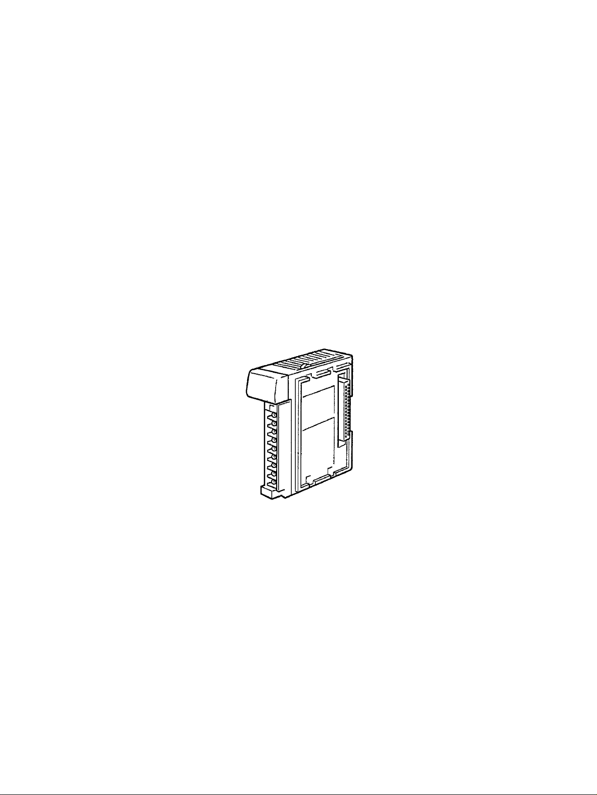
PART I B7A Interface Unit
CQM1-B7A02
CQM1-B7A03
CQM1-B7A12
CQM1-B7A13
CQM1-B7A21
1
Page 21

Page 22

SECTION 1
Features and System Configuration
This section describes the general features, system configuration, and word allocation of the CQM1-B7A@@ Interface
Units.
1-1 Features. . . . . . . . . . . . . . . . . . . . . . . . . . . . . . . . . . . . . . . . . . . . . . . . . . . . . . 4
1-2 System Configuration . . . . . . . . . . . . . . . . . . . . . . . . . . . . . . . . . . . . . . . . . . . 5
1-3 Connecting Devices . . . . . . . . . . . . . . . . . . . . . . . . . . . . . . . . . . . . . . . . . . . . 5
1-3-1 CPU. . . . . . . . . . . . . . . . . . . . . . . . . . . . . . . . . . . . . . . . . . . . . . . . . . 5
1-3-2 B7A Link Terminal. . . . . . . . . . . . . . . . . . . . . . . . . . . . . . . . . . . . . . 5
1-4 Word Allocation . . . . . . . . . . . . . . . . . . . . . . . . . . . . . . . . . . . . . . . . . . . . . . . 6
1-5 Bit Allocation . . . . . . . . . . . . . . . . . . . . . . . . . . . . . . . . . . . . . . . . . . . . . . . . . 7
3
Page 23
Features Section 1-1
1-1 Features
• The CQM1-B7A@@ Interface Unit incorporates the B7A transmission
operations for the CQM1H/CQM1 I/O Unit.
• The following five models of CQM1H/CQM1 B7A Inter face Unit are available.
Model No. of points
Input Output
CQM1-B7A21 16 16
CQM1-B7A13 32 0
CQM1-B7A03 0 32
CQM1-B7A12 16 0
CQM1-B7A02 0 16
• Each Unit ca n be connected to the same number of poin ts on 16-point
B7A Link Terminals as provided by the Unit. For example, two B7A Link
Terminal Units with 1 6 input points each can be connected to a CQM1B7A13.
• The transm ission de lay time can be switched betwe en STANDARD (19.2
ms rated) or RAPID (3 ms rated).
• The data pr ocessing when a transmission error oc curs can be switched
between HOLD (see note 1) and LOAD OFF (see note 2).
• The CPU treats the B7A Interface Units as the equivalent number of
points. It can handle remo te I/O e quipme nt, su ch as switches and la mps,
without recognizing communications.
Differences Between
CQM1-B7A01 and
CQM1-B7A21
Note 1. HOLD: When an error occurs, the input bit s tatu s imm edi ate ly prior to the
error is held.
2. LOAD OFF: When an error occurs, all input bits turn off.
The B7A Link Terminal is a terminal board that incorporates a communicatio n
function, connects to exter nal I/O devices, and com municate s wit h a P C over
a single cable, thus reducing wiring effort.
CQM1-B7A21 is an upgraded version of the CQM1-B7A01 and can repl ace
the CQM1-B7A01.
The features listed in the table below have been added to the CQM1-B7A21.
Item CQM1-B7A01 CQM1-B7A21
Transmission delay time STANDARD only STANDARD/RAPID
switchable
Transmission error
processing
HOLD HOLD/LOAD OFF switchable
Note CQM1-B7A01 is no longer in production. Use the upgraded CQM1-B7A21.
4
Page 24
System Configuration Section 1-2
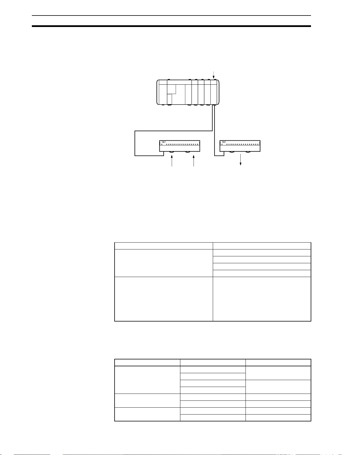
1-2 System Configuration
The following is a CQM1H/CQM1 sy stem configuration with a B7A Interface
Unit.
Note The maximum transmission di stance depe nds on the transmiss ion del ay time
and the power supply wiring.
Refer to 3-1 Connections to B7A Link Terminals.
1-3 Connecting Devices
1-3-1 CPU
The B7A Interface Unit connects to the following CPUs.
CQM1H-series CPU CQM1H-CPU11
CQM1-series CPU CQM1-CPU11-E
CQM1H/CQM1
B7A Interface Unit
Transmission distance: 500 m max.
B7A Link Terminal (for input) B7A Link Terminal (for output)
Switch Sensor Lamps
Name Model
CQM1H-CPU21
CQM1H-CPU51
CQM1H-CPU61
CQM1-CPU21-E
CQM1-CPU41-EV1
CQM1-CPU42-EV1
CQM1-CPU43-EV1
CQM1-CPU44-EV1
1-3-2 B7A Link Terminal
The B7A Interface Unit connects to the following 16-poin t B7 A Link Terminals
with a standard I/O delay of 19.2 ms (typical).
Input
Screw terminal models B7A-T6@1 STANDARD (19.2 ms)
Module models B7A-T6D2 STANDARD (19.2 ms)
PC connector models B7A-T@E3 STANDARD (19.2 ms)
Name Model Transmission delay time
B7AS-T6@1
B7A-T6@6 RAPID (3 ms)
B7AS-T6@6
B7A-T6D7 RAPID (3 ms)
B7A-T@E8 RAPID (3 ms)
5
Page 25

Word Allocation Section 1-4
Output
Name Model Transmission delay time
Screw terminal model B7A-R6@@1 STANDARD (19.2 ms)
B7AS-R6@@1
B7A-R6@@6 RAPID (3 ms)
B7AS-R6@@6
Module model B7A-R6A52 STANDARD (19.2 ms)
B7A-R6A57 RAPID (3 ms)
PC connector models B7A-R@A@3 STANDARD (19.2 ms)
B7A-R@A@8 RAPID (3 ms)
Note Combine B7A Interface Units and B7A Link Terminals with equal transmission
delay times.
Transmission errors will occur if the transmission delay times used in the combination are not equal.
Do not connect B7A Link Terminals with 10 points and I/O mi xed points. Connect only 16-point transmission models.
1-4 Word Allocation
The CPU treats the B7A Int erface Unit as an equi valent numbe r of co nne cted
I/O Units. The words allocation is identical to that for I/O Units, with inputs and
outputs allocated from left to right.
6
Page 26
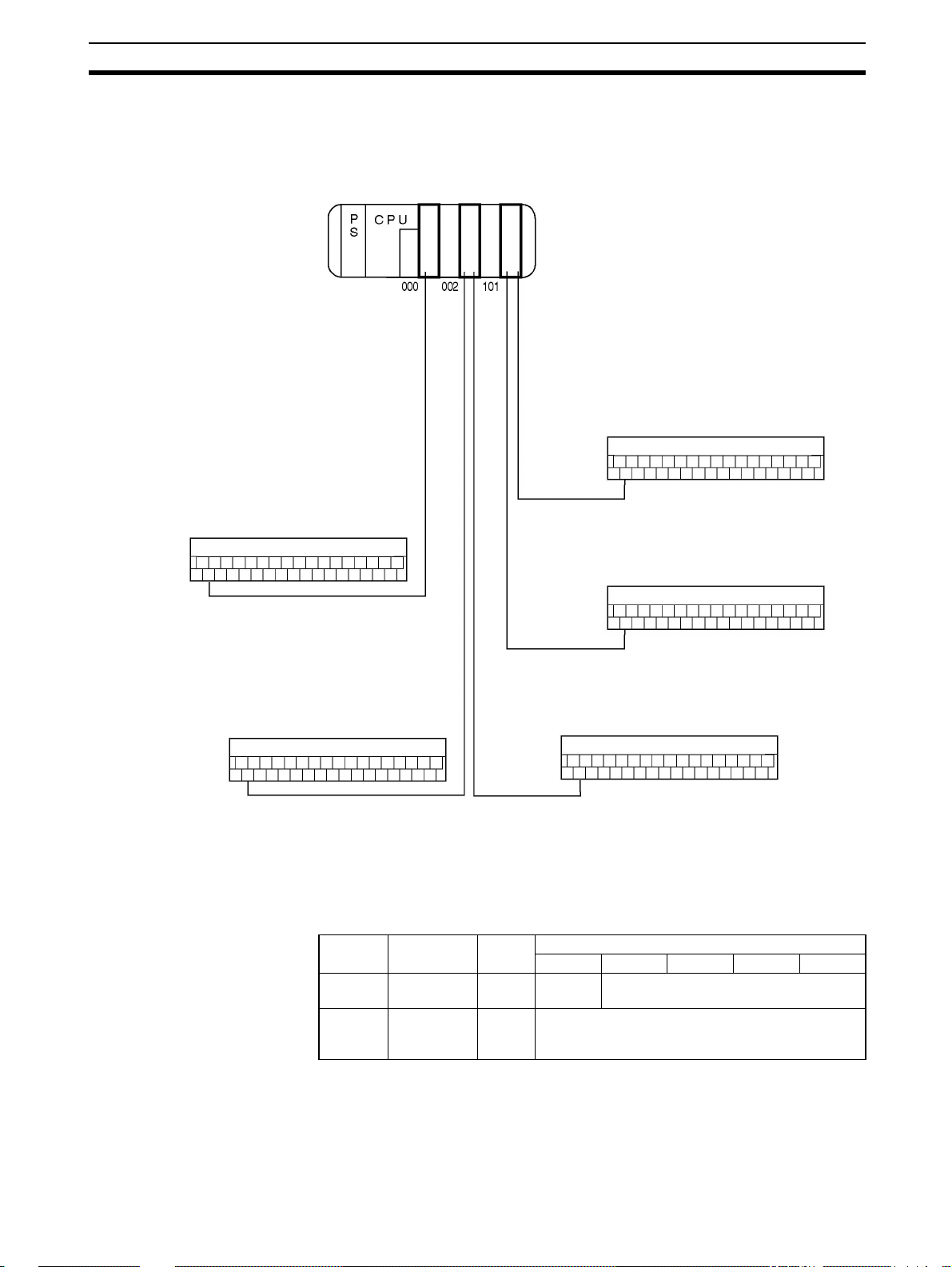
Bit Allocation Section 1-5
Words from 000 including the input bits incorporated by the CPU are allocated
for input and words from 100 are allocated for output as shown in the following
illustration. Refer to the CQM1H or CQM1 Operation Manual for details on I/O
word allocation.
CQM1H/CQM1
PS : Power Supply Unit
CPU : CPU
IN : Input Unit and terminals
OUT : Output Unit
B7A21 : B7A Interface Unit
(16 input and 16 output points)
B7A12 : B7A Interface Unit
(16 input points)
B7A03 : B7A Interface Unit
(16 output points)
B7A Link Terminal (for output)
Word 103
Points: 0 to 15
Bit no.: 10300 to 10315
Word
B7A Link Terminal (for input)
16
pts
IN
IN
B7A12
16
pts
OUT
B7A21
16
pts
Connection terminals 1
B7A03
Connection terminals 2
Word 001
Points: 0 to 15
Bit no.: 00100 to 00115
B7A Link Terminal (for input)
Word 003
Points: 0 to 15
Bit no.: 00300 to 00315
1-5 Bit Allocation
CQM1-B7A21
B7A Link Terminal (for output)
Word 102
Points: 0 to 15
Bit no.: 10200 to 10215
B7A Link Terminal (for output)
Word 100
Points: 0 to 15
Bit no.: 10000 to 10015
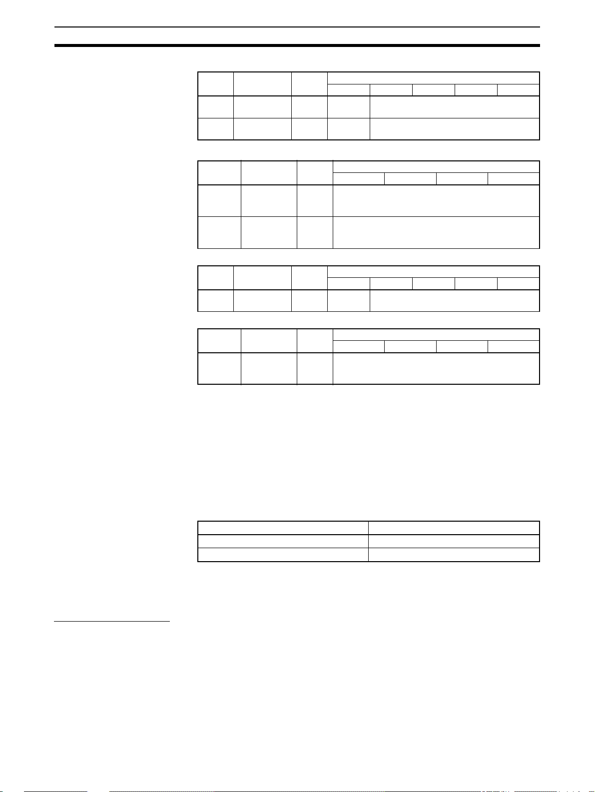
The bit allocation for each model is described below.
I/O Word no. Termi-
Input n
Output
(see
note 3)
(see note 2)
m
(see note 2)
nal
1See
2 Output bits
15 14 to 12 11 to 8 7 to 4 3 to 0
Input bits
note 1
Bit
7
Page 27
Bit Allocation Section 1-5
CQM-B7A13
CQM1-B7A03
CQM1-B7A12
CQM1-B7A02
I/O Word no. Termi-
nal
Input n 1 See
Input n + 1 2 See
I/O Word no. Termi-
nal
Output
(see
note 3)
Output
(see
note 3)
I/O Word no. Termi-
Input n 1 See note
I/O Word no. Termi-
Output
(see
note 3)
m 1 Output bits
m + 1 2 Output bit s
nal
nal
m 1 Output bits
15 14 to 12 11 to 8 7 to 4 3 to 0
Input bits
note 1
Input bits
note 1
15 to 12 11 to 8 7 to 4 3 to 0
15 14 to 12 11 to 8 7 to 4 3 to 0
Input bits
1
15 to 12 11 to 8 7 to 4 3 to 0
Note 1. Bit 15 of the input addre ss is allocated as follows, accordi ng to the DIP
switch input mode setting.
15-point input + 1 error mode setting = transmission error bit
16-point input = input bit 15
Refer to 2-2 Switch Settings.
2. Start word address (n: input, m: output)
3. See the following caution.
Bit
Bit
Bit
Bit
!Caution The minimum input time (minimum required time to read input signal from
CPU) at output bit of the B7A Interface Unit is as follows:
Transmission delay time Minimum input time
STANDARD (19.2 ms) 16 ms
RAPID (3 ms) 2.4 ms
When a user program is created, make sure the ON/O FF signal range from
the CPU to the B7A Interface Unit’s output bit is larger th an th e above values.
If smaller than the above values, data might not be correct transmitted.
Transmission Errors
Power On If the input mode is set to 15IN+ERR, the transmission error bit becomes OFF
when the CQM1H/CQM1 power is turned on.
The transmission error bi t tur ns O N if nor m al transmi ssion wit h the inpu t B7A
Link Terminal is not established within 10 ms.
All input bits remain OFF from the tim e CQM1H/CQM 1 is turn ed on until nor-
mal transmission is established.
8
Page 28

Bit Allocation Section 1-5
Inputs When a transmission error occurs, the input bits are proces sed according to
the transmission error processing setting: HOLD or LOAD OFF.
If the input mode is set to 15IN+ERR, the transmission error bit turns ON.
The transmission error bit turns OFF when nor mal transmission is re-est ab-
lished.
The normally received signals are then input to the input bits.
Outputs A transmission error with an output B7A Link Terminal can only be detected at
the Link Terminal . Co nfirm the error wi th the L ink Terminal ERR indicator and
error output.
9
Page 29

Page 30

Nomenclature and Settings
This section provides the nomenclature and switch settings for the CQM1-B7A@@ Interface Units.
2-1 Nomenclature . . . . . . . . . . . . . . . . . . . . . . . . . . . . . . . . . . . . . . . . . . . . . . . . . 12
2-2 Switch Settings . . . . . . . . . . . . . . . . . . . . . . . . . . . . . . . . . . . . . . . . . . . . . . . . 17
SECTION 2
11
Page 31

Nomenclature Section 2-1
2-1 Nomenclature
CQM1-B7A21
Front View
Indicators (see following table)
B7A Link Terminal connection terminals 1
For connection of a 16-point output B7A Link Terminal.
B7A Link Terminal connection terminals 2
For connection of a 16-point Input B7A Link Terminal.
Indicators
External power terminals
Required for transmission with the B7A Link Terminal. Connect a 12- to-24 VDC power supply.
Terminal screws: M3
(Optimum tightening torque: 0.5 N • m)
Name Color Function
RD Y Unit ready Green Lit while the CQM1H/CQM1 is supplied w ith
ERR Input
3ms Transmission
LOAD
OFF
15IN+ERR Input mode Orange Lit while input mode is set to 15IN+ERR.
transmission
error
delay time
Transmission
error
processing
Red Lit if the B7A Link Terminal for input is mal-
Orange Lit while transmission delay time is set to
Orange Lit while transmission error processing is
power.
functioning or the B7A Link Terminal for
input is disconnected.
RAPID (3 ms). Not lit when set to STANDARD (19.2 ms).
set to LOAD OFF. Not lit when set to HOLD .
Not lit when set to 16IN.
12
Page 32

Nomenclature Section 2-1
CQM1-B7A13
Front View
Indicators (see following table)
B7A Link Terminal connection terminals 1
For connection of a 16-point Input B7A Link Terminal.
Inputs least-significant word (n) data.
B7A Link Terminal connection terminals 2
For connection of a 16-point Input B7A Link Terminal.
Inputs most-significant word (n+1) data.
External power terminals
Required for transmission with the B7A Link Terminal. Connect a 12- to 24-VDC power supply.
Indicators
Terminal screws: M3
(Optimum tightening torque: 0.5 N • m)
Name Color Function
RD Y Unit ready Green Lit while the CQM1H/CQM1 is supplied w ith
power.
3ms Transmission
LOAD
OFF
15IN+ERR Input mode Orange Lit while input mode is set to 15IN+ERR.
ERR1 Input 1
ERR2 Input 2
delay time
Transmission
error
processing
transmission
error
transmission
error
Orange Lit while transmission delay time is set to
RAPID (3 ms). Not lit when set to STANDARD (19.2 ms).
Orange Lit while transmission error processing is
set to LOAD OFF. Not lit when set to HOLD .
Not lit when set to 16IN.
Red Lit when normal tra nsm is s ion with th e Input
B7A Link Terminal connecte d to conne ction
terminals 1 is not possible or when no Input
B7A Link Terminal is connected.
Red Lit when normal tra nsm is s ion with th e Input
B7A Link Terminal connecte d to conne ction
terminals 2 is not possible or when no Input
B7A Link Terminal is connected.
13
Page 33

Nomenclature Section 2-1
CQM1-B7A03
Front View
Indicators (see following table)
B7A Link Terminal connection terminals 1
For connection of a 16-point output B7A Link Terminal.
outputs least-significant word (m) data.
B7A Link Terminal connection terminals 2
For connection of a 16-point output B7A Link Terminal.
outputs most-significant word (m+1) data.
External power terminals
Required for transmission with the B7A Link Terminal. Connect a 12- to 24-VDC power supply.
Indicators
Terminal screws: M3
(Optimum tightening torque: 0.5 N • m)
Name Color Function
RD Y Unit ready Green Lit while the CQM1H/CQM1 is supplied with
power.
19ms/3ms Transmission
delay time
Orange Lit while transmission delay time is set to
RAPID (3 ms). Not lit when set to STANDARD (19.2 ms).
14
Page 34

Nomenclature Section 2-1
CQM1-B7A12
Front View
Indicators (see following table)
B7A Link Terminal connection terminals 1
For connection of a 16-point Input B7A Link Terminal.
External power terminals
Required for transmission with the B7A Link Terminal. Connect a 12- to-24 VDC power supply.
Indicators
Terminal screws: M3
(Optimum tightening torque: 0.5 N • m)
Name Color Function
RD Y Unit ready Green Lit while the CQM1H/CQM1 is supplied w ith
ERR Input
3ms Transmission
LOAD
OFF
15IN+ERR Input mode Orange Lit while input mode is set to 15IN+ERR.
transmission
error
delay time
Transmission
error
processing
Red Lit if the B7A Link Terminal for input is mal-
Orange Lit while transmission delay time is set to
Orange Lit while transmission error processing is
power.
functioning or the B7A Link Terminal for
input is disconnected.
RAPID (3 ms). Not lit when set to STANDARD (19.2 ms).
set to LOAD OFF. Not lit when set to HOLD .
Not lit when set to 16IN.
15
Page 35

Nomenclature Section 2-1
CQM1-B7A02
Front View
Indicators (see following table)
B7A Link Terminal connection terminals 1
For connection of a 16-point output B7A Link Terminal.
External power terminals
Required for transmission with the B7A Link Terminal. Connect a 12- to 24-VDC power supply.
Terminal screws: M3
(Optimum tightening torque: 0.5 N • m)
Indicators
Name Color Function
RD Y Unit ready Green Lit while the CQM1H/CQM1 is supplied w ith
19ms/3ms Transmission
delay time
Left-side View Common to all models.
power.
Orange Lit while transmission delay time is set to
RAPID (3 ms). Not lit when set to STANDARD (19.2 ms).
Operation setting DIP Switch
Sets to the operation of the
B7A Interface Unit (see page
15). Set the switches before
mounting the B7A Interface
Unit in CQM1H/CQM1. To set
after mounting, remove the terminal block and make the setting from the front face.
16
Page 36

Switch Settings Section 2-2
→
→
2-2 Switch Settings
Remove the terminal block to expose the DIP switch under n eat h. Refer to the
CQM1H Operation Manual (W 363) or the CQM1 Operation Manual (W226)
for the method of removing the terminal block.
Use a thin-tipped object, such as a small screwdriver, to set the pins.
DIP switch
CQM1-B7A21/CQM1-B7A12
Pin no. Setting OFF ON
4 Transmission delay
time
3 Transmission error
processing
2 Input mode 16IN 15IN+ERR
1 ERR indicator Not lit Lit
STANDARD (19.2 ms) RAPID (3 ms)
HOLD LOAD OFF
→
Note On delivery from the factory, pin 1 is set ON and all others OFF.
CQM1-B7A03/CQM1-B7A02
Pin no. Setting OFF ON
4 Transmission delay
time
3 Not used (set OFF) ––– –––
2 Not used (set OFF) ––– –––
1 Not used (set OFF) ––– –––
STANDARD (19.2 ms) RAPID (3 ms)
Note On delivery from the factory, all pins set OFF.
CQM1-B7A13
Pin no. Setting OFF ON
6 Transmission delay
time
5 Transmission error
processing
4 Input mode 16IN 15IN+ERR
3 ERR1 indicator Not lit Lit
2 ERR2 indicator Not lit Lit
1 Not used (set OFF) ––– –––
STANDARD (19.2 ms) RAPID (3 ms)
HOLD LOAD OFF
Note On delivery from the factory, pins 2 and 3 are set ON and all others OFF.
!Caution Turn off the CQM1H/CQM1 power before setting the pins.
17
Page 37

Switch Settings Section 2-2
Transmission Delay Time
Setting
Sets the transmission delay time for the B7A Interface Unit.
Setting Transmission Delay Time
ON RAPID (3 ms)
OFF STANDARD (19.2 ms) (factory setting)
Set the transmission delay time to RAPID to enable transmis sion with highspeed B7A Link Terminals with a transmission delay time of 3 ms. Set the
transmission delay time to STANDARD to enable transmission with standar d
B7A Link Terminals with a transmission delay time of 19.2 ms.
Set the pin to match the transmis sion delay time of the type of B7 A Link Terminal connected. A transm ission erro r will oc cur if t he sett ing doe s n ot matc h
the transmission delay time of the B7A Link Terminal.
The transmission delay time setting is made for the entire Uni t. It is no t pos sible to make separate settings for each word if multiple words are used.
Transmission Error
Processing Setting
This setting deter mines whether the input bit status immed iately prior to th e
error is held when a transmission error occurs (HOLD) or whether all input bits
turn off (LOAD OFF).
Setting Transmission error processing
ON LOAD OFF
OFF HOLD (factory setting)
Input Mode Setting Set the input mode (the use of bit 15) from the Input B7A Link Terminal to one
of the modes shown in the table below. Match the pin setting to the Input B7A
Link Terminal.
Setting Input mode Description
ON 15-point input + 1 error
(15IN+ERR)
OFF 16-point input (16IN) Bit 15 also used as a normal input bit. The
Bit 15 used as transmission error bit. The
bits available for input are the 15 bits from
00 to 14.
bits available for input are the 16 bits from
00 to 15. (factory setting)
ERR Indicator Lighting
Setting
Sets whether the ERR indicator lights when an input transmission error
occurs.
Setting Description
ON ERR indicator lights (factory setting)
OFF ERR indicator does not light
To avoid indicator lighting unnecessari ly, set pin OFF if the input side of the
B7A Interface Unit is not used.
18
Page 38

SECTION 3 Connections
This section describes the connections between the CQM1-B7A@@ Interface Units and B7A Link Terminals.
3-1 Connections to B7A Link Terminals. . . . . . . . . . . . . . . . . . . . . . . . . . . . . . . . 20
3-1-1 Recommended Cables . . . . . . . . . . . . . . . . . . . . . . . . . . . . . . . . . . . 20
3-1-2 Connecting Terminals. . . . . . . . . . . . . . . . . . . . . . . . . . . . . . . . . . . . 20
3-2 Wiring . . . . . . . . . . . . . . . . . . . . . . . . . . . . . . . . . . . . . . . . . . . . . . . . . . . . . . . 22
19
Page 39

Connections to B7A Link Terminals Section 3-1
3-1 Connections to B7A Link Terminals
3-1-1 Recommended Cables
The B7A Interface Unit can be connected to the input an d output B7A Link
Terminals using the following cables.
Standard Transmission Delay-time Type
Cabtire Cable Use a VCTF 0.75 x 3 C cabtire cable (100 m max.) if a power supply is shared
and a VCTF 0.75 x 2 C cabtire cable (500 m max.) if power is s upplied independently.
Rapid Transmission Delay-time Type
Shielded Cable Use a 0.75 x 3 C shielded cable (50 m max.) if a power supply is shared and a
0.75 x 2 C shielded cable (100 m max.) if power is supplied independently.
!Caution If shielded cable is not used for the high-sp eed transmission delay-time Link
Terminal, the transmission distance is not to exceed 10 m regardless of
whether power supply is shared or wired separately.
3-1-2 Connecting Terminals
CQM1-B7A21
CQM1-B7A13
Connect the input and output B7A Link Terminals to the B7A Interface Unit via
the following terminal s using cr imp-style term inals used for CQM1H /CQM1 I/
O Units.
Connect to the SIG terminal of
the output B7A Link terminal.
B
Unused
Unused
0
A
0
B
1
A
1
B
2
A
2
B
3
A
3
B
0
A
0
B
1
A
1
B
2
A
2
B
3
A
3
Connect to the negative power supply terminal of the output B7A Link Terminal.
Connect to the SIG terminal of
the input B7A Link Terminal.
Connect to the negative power supply terminal of the input B7A Link Terminal.
Connect to the SIG terminal of
the input B7A Link terminal.
Connect to the negative power supply terminal of the input B7A Link Terminal.
Connect to the SIG terminal of
the input B7A Link Terminal.
Connect to the negative power supply terminal of the input B7A Link Terminal.
Word m
Word n
Word n
Word n + 1
20
Page 40

Connections to B7A Link Terminals Section 3-1
CQM1-B7A03
Connect to the SIG terminal of
the output B7A Link terminal.
Connect to the negative power supply terminal of the output B7A Link Terminal.
Connect to the SIG terminal of
the output B7A Link Terminal.
Connect to the negative power supply terminal of the output B7A Link Terminal.
Connect to the SIG terminal of
the input B7A Link terminal.
0
1
2
3
Connect to the negative power supply terminal of the input B7A Link Terminal.
Unused
Word m
Word m + 1
Word n
CQM1-B7A12
Unused
Unused
B
0
A
0
B
1
A
1
B
2
A
2
B
3
A
3
B
A
0
B
A
1
B
A
2
B
A
3
CQM1-B7A02
Connect to the SIG terminal of
the output B7A Link terminal.
Word m
Connect to the negative power supply terminal of the output B7A Link Terminal.
Unused
Unused
B
0
A
0
B
1
A
1
B
2
A
2
B
3
A
3
Connectors Crimp connectors for I/O Unit wiring should be l ess than 6.2 mm wide (M 3),
and the wire should be AWG22 to 18 (0.3 to 0.75 mm
2)
.
Terminal screws should be tightened with a torque of 0.5 N • m.
6.2 mm max.
6.2 mm max.
!Caution Forked crimp connectors are required by UL and CSA standards.
21
Page 41

Wiring Section 3-2
3-2 Wiring
Wiring between the B 7A Interface Unit, input B7A Link Terminal, and output
B7A Link Terminal s haring a si ngle power supply differs from wi ring between
Units using independent power supplies as shown in the following diagrams.
Standard Transmission Delay-time Link Terminal
Single Power Supply
B7A Interface Unit
Terminal screws: M3
–
+
12 to 24 VDC
Independent Po wer Supplies
B7A Interface Unit
Terminal screws: M3
Terminal screws: M3.5
Transmission distance: 100 m max.
–
2
Transmission cable: VCTF 0.75 mm
Transmission distance: 500 m max.
min.
Terminal screws: M3.5
12 to 24 VDC
+
B7A Link Terminal
B7A Link Terminal
B7A Link Terminal
22
12 to 24 VDC
–
–
12 to 24 VDC
+
Transmission cable: VCTF 0.75 mm
2
min.
+
B7A Link Terminal
Note 1. The transmission distance depends on the type of wiring used.
2. The size of termi nal s crew differs for the B7A In terface Unit a nd B7A Link
T erminal. Consider the size of the terminal screws when using crimped terminals.
Page 42

Wiring Section 3-2
3. Locate transmission c ables away from power cables and high -voltage c ables to eliminate the effects of noise.
Rapid Transmission Delay-time Link Terminal
Single Power Supply
Terminal screws: M3.5
B7A Interface Unit
Terminal screws: M3
–
–
+
12 to 24 VDC
Independent Po wer Supplies
B7A Interface Unit
Terminal screws: M3
Ground
Ground
Transmission distance:
50 m max.
Shielded cable:
0.75 mm
Transmission cable:
shielded, 0.75 mm
Transmission distance:
50 m max.
2
min.
2
min.
Terminal screws: M3.5
12 to 24 VDC
B7A Link Terminal
B7A Link Terminal
+
B7A Link Terminal
12 to 24 VDC
–
–
+
Ground
Shielded cable:
0.75 mm
2
min.
Transmission cable:
shielded, 0.75 mm
12 to 24 VDC
2
min.
+
B7A Link Terminal
Ground
Note 1. The transmission distance depends on the type of wiring used.
2. The size of termi nal s crew differs for the B7A In terface Unit a nd B7A Link
T erminal. Consider the size of the terminal screws when using crimped terminals.
3. It is recommend that the shield wire be grounded.
23
Page 43

Wiring Section 3-2
4. If shielded cable is not us ed, the transmission distan ce is not to exceed
10 m regard less of whe ther power supply i s common or wired sep arately
(using VCTF 0.75 mm
5. Locate transmission c ables away from power cables and high -voltage cables to eliminate the effects of noise.
2
min.).
24
Page 44

Appendix A
Specifications
Standard Specifications
The standard specifications of the B7A Interface Unit conform to those of the CQM1H/CQM1 PC.
Performance Specifications
Item Specification
I/O points B7A21: 16 input points (see note 1), 16 output points
B7A13: 32 input points (see note 2)
B7A03: 32 output points
B7A12: 16 input points (see note 1)
B7A02: 16 output points
I/O word allocation B7A21: 1 word each for input and output (2 words in total)
B7A13: 2 words for input
B7A03: 2 words for output
B7A12: 1 word for input
B7A02: 1 word for output
Communication method Unidirectional, time-division multiplex
Transmission distance
(see note 3)
Transmission delay time STANDARD: 19.2 ms (rated delay), 31 ms max.
Minimum input time
(see note 4)
Power consumption 100 mA at 5 VDC
External power supply 12 to 24 VDC ±10% (excluding the power required by the B7A Link Terminals)
Weight 200 g max.
Dimensions 32 x 110 x 107 (W x H x D) mm
STANDARD: 500 m max.
RAPID: 100 m max.
RAPID: 3 ms (rated delay), 5 ms max.
STANDARD: 16 ms
RAPID: 2.4 ms
B7A21: 0.11 A min.
B7A13: 0.07 A min.
B7A03: 0.10 A min.
B7A12: 0.05 A min.
B7A02: 0.04 A min.
1. Input mode setting allows selection between 16-point input and 15-point+1 error input.
2. Input mode setting allows selec tion between 32- point input and 30-point+2 err or input. Re fer to 2-2
Switch Settings.
3. The maximum transmission distance of the B7A Interface Unit varies with the transmission delay time
and the method of wiring. Refer to 3-1 Connections to B7A Link Terminals for details.
4. Minimum input time is the minimum required time to read an input signal from the CPU. The ON/OFF
signal range from the CPU to the B7A Inter face Unit’s output bit should be larger than the mi nimum
input time.
25
Page 45

Specifications Appendix A
Dimensions
These dimensions are the same for all B7A Interface Unit models.
(Unit: mm)
26
Page 46

PART II G730 Interface Unit
CQM1-G7M21
CQM1-G7N01
CQM1-G7N11
27
Page 47

Page 48

SECTION 1
Features and System Configuration
This section describes the general features, system configuration, and word allocation of the G730 Interface Units.
1-1 Features. . . . . . . . . . . . . . . . . . . . . . . . . . . . . . . . . . . . . . . . . . . . . . . . . . . . . . 30
1-2 System Configuration . . . . . . . . . . . . . . . . . . . . . . . . . . . . . . . . . . . . . . . . . . . 31
1-3 Connecting Devices . . . . . . . . . . . . . . . . . . . . . . . . . . . . . . . . . . . . . . . . . . . . 34
1-3-1 CPU. . . . . . . . . . . . . . . . . . . . . . . . . . . . . . . . . . . . . . . . . . . . . . . . . . 34
1-3-2 G730 Remote Terminal (Slave) . . . . . . . . . . . . . . . . . . . . . . . . . . . . 34
29
Page 49

Features Section 1-1
1-1 Features
The CPU handles the Interface Units as I/O Units, thereby eliminating tedious
procedures. Using a G730 Interface Unit allows signa ls for remote I/O equipment, such as switches and lam ps, to b e ha ndl ed and co ntr olled by the G730
Remote Terminal.
The G730 Remote Termin al is a terminal block with added communications
functions. It is connected to remote I/O equipment and PC s. Connecti on to
the PC by a single pair of cables reduces wiring effort.
For more information about the G730 Remote Terminal, refer to the I/O T ermi-
nal Series Catalog (X044).
CQM1-G7M21 Master Switch settings on the Master allow simultaneous connection of G730
Remote Terminals (Slaves) with up to 32 input points and 32 output points.
Up to two Expansion Maste rs c an be con nec te d to ea ch Mas ter ( one syst em)
to permit control of up to 128 points.
Multiple Masters can be used.
Connection of multiple Masters in separate systems permits control within the
range permitted for the CPU.
The number of inpu t points a nd ou tput poin ts can in depend ently be switche d
between 32 and 16.
The HOLD/HOLD OFF setting d etermines whether the si gnals into the CPU
are held (HOLD) or cleared (HOLD OFF) when a transmission error occurs.
CQM1-G7N@1 Expansion
Master
An Expansion Master is used if the Master alone does not allow connection of
sufficient points. The Exp ansion Ma sters are always connected in series with
the Master and up to two Expansion Mas ters can be c onnected to eac h Master.
Expansion Masters are available as Input Units (G7N11) and Output Units
(G7N01). Switch settings allow connection of G730 Remote Terminals
(Slaves) with up to 32 points.
The number of inpu t points a nd ou tput poin ts can in depend ently be switche d
between 32 and 16 for both Input Units and Output Units.
30
Page 50

System Configuration Section 1-2
1-2 System Configuration
The following are CQM1H/CQM1 system configu ration examples with G730
Interface Units.
Configuration with One Master
Master (32 input points/32 output points max.)
CQM1H/CQM1
RS-485, 200 m max.
G730-VI (input model) G730-VO (output model) G730-RI (input model) G730-RO (output model)
Switch Sensor Lamp ValveSwitch
Note 1. Sw itches o n the M aster allow in put and output to be i ndepen dently set t o
2 words (32 points) or 1 word (16 points). Connect Slaves according to the
set number of points.
2. If both input and output are set to 2 words (32 points), up to eight Input
Units and eight Output Units can be connected, if 4-point Slaves are used.
31
Page 51

System Configuration Section 1-2
Configuration as a Single System with Expansion Masters
Master (32 input points/32 output points max.)
Expansion Master Unit 1 (max. 32 input points or 32 output points)
CQM1H/CQM1
RS-485, 200 m max.
G730-VI (input model) G730-VO (output model) G730-RI (input model) G730-RO (output model)
Switch Sensor Lamp ValveSwitch
Expansion Master Unit 2 (max. 32 input points or 32 output points)
Note 1. Use one Master in any system. The systems must be separated if multiple
Masters are used. (See page 33)
2. Up to two Expansion Masters can be connected to each Master.
3. When two Expansion Masters are used, set one as Unit 1 and the other as
Unit 2. The Slave address for Unit 2 can only be used for an 8-point or 16point Slave. It cannot be used for a 4-point Slave.
4. The combination of one Master with two Expansion Masters allows control
of up to 128 points.
5. The maximum number o f connectable Slaves is 24 4-poi nt Slaves and 4
8-point Slaves, making a total or 28 Units.
32
Page 52

System Configuration Section 1-2
Configuration as Multiple Systems
Master, System 1 (32 input points/32 output points max.)
Expansion Master Unit 1 (max. 32 input points or 32 output points)
Expansion Master Unit 2 (max. 32 input points or 32 output points)
Master, System 2 (32 input points/32 output points max.)
Expansion Master Unit 1 (max. 32 input points or 32 output points)
RS-485, 200 m max.
G730-VI (input model) G730-VO (output model) G730-RI (input model)
Switch Sensor Lamp ValveSwitch
G730-VI (input model) G730-VO (output model) G730-RI (input model) G730-RO (output model)
Switch Sensor Lamp ValveSwitch
G730-RO (output model)
Note 1. Wh en multi ple Ma st er s ar e us ed , al lo ca te s ystem numbers to them i n s e-
quence from 1, starting from the Master nearest the CPU. The system
numbers have no special significance. Refer to 4-1 Word Allocation.
2. Up to two Expansion Masters can be connected to each Master.
3. When two Expansion Masters are used, set one as Unit 1 and the other as
Unit 2. The Slave address for Unit 2 can only be used for an 8-point or 16point Slave. It cannot be used for a 4-point Slave.
4. Masters and Expansion Masters can be used in any combination, provided
that the maximum numb er of input and output points remains with in the
range permitted for the CPU.
33
Page 53

Connecting Devices Section 1-3
1-3 Connecting Devices
1-3-1 CPU
The G730 Interface Unit connects to the following CPUs.
Name Model Max. I/O Points (see note)
CQM1H-series CQM1H-CPU11 256 (16 words)
CQM1H-CPU21
CQM1H-CPU51 512 (32 words)
CQM1H-CPU61
CQM1-series CQM1-CPU11-E 128 (8 words)
CQM1-CPU21-E
CQM1-CPU41-EV1 256 (16 words)
CQM1-CPU42-EV1
CQM1-CPU43-EV1
CQM1-CPU44-EV1
Note The number of points includes the CP U internal 16 input poin ts (one word).
Therefore, the actual maximum number s of points usable by the G73 0 Interface Unit are 112 points (7 words), 240 points (1 5 words), and 49 6 points (3 1
words) respectively.
1-3-2 G730 Remote Terminal (Slave)
The following G730 Remote Terminals can be connected to a G730 Inter face
Unit.
Model I/O type I/O points
G730-RID04 Relay input (DC) 4
G730-RIA04 Re lay input (AC)
G730-ROC04 Re lay output
G730-ROC04-A Relay output (with error detection function)
G730-VID04 DC inp ut, NPN (comm on +)
G730-VOD04 Transistor output , NPN (common –)
G730-ROC08 Re lay output 8
G730-AOM08 Relay output (power MOS FET)
G730-VID08 DC inp ut, NPN (comm on +)
G730-VID08-1 DC input, PNP (common –)
G730-VOD08 Transistor output , NPN (common –)
G730-VOD08-1 Transistor output, PNP (common +)
G730-ROC16 Relay output 16
G730-AOM16 Relay output (power MOS FET)
G730-VID16 DC inp ut, NPN (comm on +)
G730-VOD16 Transistor output , NPN (common –)
For more information about the G730 Remote Terminal, refer to the I/O T ermi-
nal Series Catalog (X044).
34
Page 54

Nomenclature and Settings
This section provides the nomenclature and switch settings for the G730 Interface Units.
2-1 Nomenclature . . . . . . . . . . . . . . . . . . . . . . . . . . . . . . . . . . . . . . . . . . . . . . . . . 36
2-2 Switch Settings . . . . . . . . . . . . . . . . . . . . . . . . . . . . . . . . . . . . . . . . . . . . . . . . 39
SECTION 2
35
Page 55

Nomenclature Section 2-1
2-1 Nomenclature
CQM1-G7M21 Ma st er
Front View
Indicators (see following table)
+
Transmission terminal
(Refer to 3-1 Transmission Cables)
Transmission Ready terminals
(Refer to 3-2 External Output
Connection Cables)
Terminals shorted while in transmission status with power on.
Read signal at CPU and confirm
transmission ready status before enabling data.
Refer to 4-2 Handling Power On.
The output from these ter-
minals linked to ON/OFF status
of the T/R RDY indicator.
ALM output terminals
(Refer to 3-2 External Output
Connection Cables)
Terminals shorted if an error occurs in the output of a unit with
error detection function
(G730-ROC04-A).
Terminal screws: M3
(Optimum tightening torque: 0.5 N • m)
–
For connection of transmission
cable to Expansion Master or
Slave.
Indicators
Name Color Function
RDY Unit Ready Green Lit wh en power is on and if CQM1H/
CQM1 recognizes a Master.
IN 1CH IN Mode Orang e Lit while number of inputs s et to 1 word
(16 points). Not lit when set to 2 words
(32 points).
OUT 1CH OUT Mode Orange Lit while nu mber of outputs set to 1
word (16 points). Not lit when set to 2
words (32 points).
T/R RDY Transmission
Ready
Green Lit while in transmission status with
power on. Not lit while in transmission
error.
HOLD HOLD Setting Orange Lit while DIP switch set to HOLD (data
held when a tr ansmission error occu rs).
T/R Transmitting Red Flashes while searching for terminator
or during transmission with power
turned on. Lit when there is a transmission error. Not lit when there is an erro r
in the Master.
END Terminator Red Lit when the power is turned on. Goes
out when the terminator is found.
Flashes when multiple terminators are
present.
36
Page 56

Nomenclature Section 2-1
Name Color Function
NODE Slave Setting
Error
ALM Slave Alarm Red Lit after error occurs with Slave output
Red Lit when Slave set to #28 to #30.
Flashes for other address setting error
(refer to Appendix B Troubleshooting
for details ).
(G730-ROC04-A).
Note ALM Output:
The Slave address and bit address cannot be checked after a failure occurs.
It is not possible to differentiate between Open and Short modes.
For more information about the G730 Remote Terminal, refer to the I/O T ermi-
nal Series Catalog (X044).
CQM1-G7N11 Input Master
Front View
Indicators (see following table)
Indicators
+
Transmission terminal 1
For connection of transmission cable from
–
Master or Expansion Master.
+
Transmission terminal 2
For connection of transmission cable to next
–
Expansion Master or Slave.
Terminal screws: M3
(Optimum tightening torque: 0.5 N • m)
Name Color Function
RDY Unit Ready Green Lit wh en power is on and if CQM1H/
IN 1CH IN Mode Orange Lit while number of inp uts s et to 1 word
ADR No.2 Unit 2 Orange Lit when Unit 2 set. Not lit when Unit 1
T/R T r ansmitting Red Flashes during transmissio n with powe r
CQM1 recognizes a Master.
(16 points). Not lit when set to 2 words
(32 points).
set.
turned on. Lit when there is a transmission error. Not lit when there is an erro r
in the Expansion Master.
(see page 44)
(see page 44)
37
Page 57

Nomenclature Section 2-1
CQM1-G7N01 Output Master
Front View
Indicators (see following table)
Indicators
+
Transmission terminal 1
–
For connection of transmission cable from
Master or Expansion Master.
+
Transmission terminal 2
–
For connection of transmission cable to next
Expansion Master or Slave.
Terminal screws: M3
(Optimum tightening torque: 0.5 N • m)
(see page 44)
(see page 44)
Name Color Function
RDY Unit Ready Green Lit wh en power is on and if CQM1H/
CQM1 recognizes a Master.
OUT 1CH OUT Mode Orange Lit while nu mber of outputs set to 1
word (16 points). Not lit when set to 2
words (32 points).
ADR No.2 Unit 2 Orange Lit when Unit 2 set. Not lit when Unit 1
set.
T/R T r ansmitting Red Flashes during transmissio n with powe r
turned on. Lit when there is a transmission error. Not lit when there is an erro r
in the Expansion Master.
38
Note The positive and negative terminals of the trans mis s io n te rminals 1 and 2 are
shorted internally.
Transmission terminals 1 and 2 can be connected in any order.
Page 58

Switch Settings Section 2-2
2-2 Switch Settings
Remove the terminal block to expose the DIP switch under n eat h. Refer to the
CQM1H Operation Manual (W 363) or the CQM1 Operation Manual (W226)
for the method of removing the terminal block.
Use a thin-tipped object, such as a small screwdriver, to set the switches.
DIP switch
CQM1-G7M21 Ma st er
All pins are factory-set
to OFF
→
OFF↔ON
Pin 4 Not used (set to OFF).
Pin 3 HOLD/HOLD OFF Setting:
Sets the HOLD/HOLD OFF function. This setting determines whether the signal input status to the CP U is held wh en a transmissio n error oc curs (HOLD)
or whether all input bits are cleared (HOLD OFF).
Setting Description
ON Signal input status held when a transmission error occurs (HOLD).
OFF Signal input status cleared when a transmission error occurs (HOLD
OFF).
Pin 2 Output Word Setting:
Sets the number of output words (points) occupied at the Master.
Setting Description
ON One word (16 points) of outputs.
OFF Two words (32 points) of outputs.
Pin 1 Input Word Setting:
Sets the number of input words (points) occupied at the Master.
Setting Description
ON One word (16 points) of inputs.
OFF Two words (32 points) of inputs.
Note 1. Even when sel ec ted , the HOLD function does not operate in the following
cases:
Error in the Master (CPU ou t of c ontrol,
etc.)
Error in Expansion Master (CPU out of
control, etc.)
Cable discontinuity between Master
and Expansion Master
Shorting in transmission route
HOLD inoperative for Master and
Expansion Masters.
HOLD operative for Master but inoperative for Exp ansion Mas ters.
39
Page 59

Switch Settings Section 2-2
2. Disconnection between Slaves:
HOLD operative for Slaves connected to Master. Inoperative for output
Slaves after the discontinuity. These status es determined by the output
Slave HOLD/HOLD OFF setting.
CQM1-G7N11 Input Expansion Master
All pins are factory-set
to OFF
→
OFF↔ON
Pins 3 and 4 Not used (set to OFF).
Pin 2 Expansion Master Unit # Setting:
Sets the Expansion Master Unit Numb er
Setting Description
ON Expansion Master is Unit 2
OFF Expansion Master is Unit 1
Pin 1 Input Word Setting:
Sets the number of input words (points) occupied at the Expansion Master.
Setting Description
ON One word (16 points) of inputs.
OFF Two words (32 points) of inputs.
Note 1. Turn the CQM1H/CQM1 power off before setting the DIP switch. The
switch settings are enabled when the CQM1H/CQM1 power is turned on.
2. Use a different Unit number for each of the two Expansion M asters used
with a single Master.
3. Slave address for Unit 2 can only be used for an 8-point or 16-point Slave.
It cannot be used for a 4-point Slave.
CQM1-G7N01 Output Expansion Master
All pins are factory-set
to OFF
→
OFF↔ON
Pins 3 and 4 Not used (set to OFF).
Pin 2 Expansion Master Unit # Setting:
Sets the Expansion Master Unit Numb er
Setting Description
ON Expansion Master is Unit 2
OFF Expansion Master is Unit 1
40
Page 60

Switch Settings Section 2-2
Pin 1 Output Word Setting:
Sets the number of output words (points) occupied at the Expansion Master.
Setting Description
ON One word (16 points) of outputs.
OFF Two words (32 points) of outputs.
Note 1. Turn the CQM1H/CQM1 power off before setting the DIP switch. The
switch settings are enabled when the CQM1H/CQM1 power is turned on.
2. Use a different Unit number for each of the two Expansion M asters used
with a single Master.
3. Slave address for Unit 2 can only be used for an 8-point or 16-point Slave.
It cannot be used for a 4-point Slave.
41
Page 61

Page 62

SECTION 3 Connections
This section describes the connections between the G730 Interface Units and G730 Remote Terminals.
3-1 Transmission Cables. . . . . . . . . . . . . . . . . . . . . . . . . . . . . . . . . . . . . . . . . . . . 44
3-2 External Output Connection Cables . . . . . . . . . . . . . . . . . . . . . . . . . . . . . . . . 45
43
Page 63

Transmission Cables Section 3-1
3-1 Transmission Cables
Connect wiring in ser ies from the Master, with positive terminals connected
together and negative terminals co nne cted together.
Set the last connected Slave as the term inator. Do not set an inter mediate
Slave as a terminator.
Total cable length per system: 200 m max.
The size of termina l screw differs for the Master and S lave. Consider the size
of the terminal screws when using solderless terminals.
Master termin al: M3 (optimum tightening torque: 0.5 N • m); Slave terminal:
M3.5 (optimum tightening torque: 0.8 N • m)
Locate transmission c ables away from power cables and high-voltage cables
to eliminate the effect s of noise.
Recommended Cables The G730 Interface Unit can be connected to the G730 Remote Terminal
using the following cable.
Cable: VCTF 0.75 x 2C
Master to Slave
Connection
G730 Interface Unit
Master
Terminal screws: M3
(Optimum tightening torque: 0.5 N • m)
Master and Expansion
Master to Slave
Connection
The connection method of a Master to Slaves is shown in the diagram below.
G730 Remote Terminal
Slave
+
−
+
−
Terminal screws: M3.5
(Optimum tightening torque: 0.8 N • m)
G730 Remote Terminal
Slave
+
−
Set as terminator.
The connection method of a Master and Expansion Master to Slaves is shown
in the following diagram.
Connect wiring o f each system in series fr om Master, Expansion Master to
Slave with positive terminals connecte d togethe r and negative ter min als connected together.
Expansion Master ter minals B0 to B2 and B1 to B3 are shorted internally.
They can be used in any combination.
Set the last connected Slave as the term inator. Do not set an inter mediate
Slave as a terminator.
Total cable length per system: 200 m max.
The size of terminal screw differs for the Master/Expansion Master and Slave.
Consider the size of the terminal screws when using crimped terminals.
Master/Expansion Master terminal: M3; Slave terminal: M3.5
44
Page 64

External Output Connection Cables Section 3-2
Locate transmission c ables away from power cables and high-voltage cables
to eliminate the effect s of noise.
G730 Interface Unit
Master
G730 Interface Unit Expansion Master
*1 *1
G730 Interface Unit Expansion Master
Terminal screws: M3
(Optimum tightening
torque: 0.5 N • m)
G730 Remote Terminal
Slave
+
–
Set as terminator. Terminal screws: M3.5
+
–
Terminal screws: M3
(Optimum tightening
torque: 0.5 N • m)
+
–
+
–
Terminal screws: M3
(Optimum tightening
torque: 0.5 N • m)
G730 Remote Terminal
Slave
+
–
(Optimum tightening torque: 0.8 N • m)
3-2 External Output Connection Cables
The G730 Interface Unit Master rel ay contact external out puts are the Transmission Ready output and ALM output.
+
–
+
–
Recommended Cables The external outputs can be connected using the following cable.
2
Cable: AWG22 to 18 (0.3 to 0.75 mm
)
45
Page 65

External Output Connection Cables Section 3-2
Connections Transmission Ready termin als are shorte d when Transmission Ready status
occurs.
Example of external
output connections
G730 Interface Unit
Master
Transmission
Ready output
ALM output
Terminal screws: M3
(Optimum tightening torque: 0.5 N • m)
The ALM output terminals are shorted if an error occurs in the output of a Unit
with error detection function (G730-ROC04-A).
Transmission Ready output/ALM output
Max. switching capacity: 24 VDC/2 A
Min. switching capacity: 5 VDC/10 mA
to CQM1H/CQM1 Input Unit, etc.
Emergency stop circuit
Power
supply
To system control circuit
46
Page 66

This section provides the operational procedures for the G730 Interface Unit.
4-1 Word Allocation . . . . . . . . . . . . . . . . . . . . . . . . . . . . . . . . . . . . . . . . . . . . . . . 48
4-1-1 CQM1H/CQM1 Word Allocation . . . . . . . . . . . . . . . . . . . . . . . . . . 48
4-1-2 Precautions . . . . . . . . . . . . . . . . . . . . . . . . . . . . . . . . . . . . . . . . . . . . 49
4-1-3 G730 Remote Terminal Allocation. . . . . . . . . . . . . . . . . . . . . . . . . . 51
4-1-4 Word Allocation Example . . . . . . . . . . . . . . . . . . . . . . . . . . . . . . . . 53
4-2 Handling Power On. . . . . . . . . . . . . . . . . . . . . . . . . . . . . . . . . . . . . . . . . . . . . 54
4-3 Transmission Delay Time . . . . . . . . . . . . . . . . . . . . . . . . . . . . . . . . . . . . . . . . 54
SECTION 4
Operation
47
Page 67

Word Allocation Section 4-1
4-1 Word Allocation
4-1-1 CQM1H/CQM1 Word Allocation
Number of I/O Words The number of I/O words for the G730 Interface Unit Master and E xpansion
Master can be switched b etween 1 word and 2 words usi ng the DIP switch.
The number of I/O words s et affects the word all ocations and num ber o f connected Slaves. Set the required number of words to suit the Slave I/O type,
number of points, and number of Units.
Unit Number of Expansion
Master
Up to two Expansion Masters can b e connec ted to each Ma ste r. Set a unique
Unit number for each Expansion Master us ing the DIP switch. Either Expansion Master can be set as Unit 2, but a Slave address for Unit 2 can only be
used for an 8-point or 16-point Slave. It cannot be used for a 4-point Slave.
If only one Expansion Master is used, set it as Unit 1.
Word Allocation Word addresses are allocated sequentially from left to right to all I/O and other
mounted units, starting from 001 for inputs (000 is the CPU internal input) and
from 100 for outputs, independent of the Master and E xpansion Master Unit
number.
In multiple systems (using multiple Masters), the word addresses are allocated to the inputs and outputs sequentially from the leftmost mounted uni t,
independent of the system number.
DIP Switch Set the DIP switch before turning the CQM1H/CQM1 power on. The switch
settings are enabled when the CQM1H/CQM1 power is turned on.
Master
(G7M21)
Set OFF
HOLD function setting
Number of output
words setting
Number of input words setting
ON: 1 word (16 points)
OFF: 2 words (32 points)
Expansion Master
(G7N11)
Expansion Master
(G7N01)
All pins are factory-set to OFF.
Example of Number of I/O
Words and Unit No.
Settings
48
Set OFF
Unit # setting
Number of input words setting
ON: 1 word (16 points)
OFF: 2 words (32 points)
ON: Unit 2
OFF: Unit 1
Set OFF
Unit # setting
Number of output words setting
ON: 1 word (16 points)
OFF: 2 words (32 points)
ON: Unit 2
OFF: Unit 1
The mounting positions of the Master and Expansion Master are not specified
but the wiring must be connected in the or der: Master to Expans ion Mas ter to
Slave. The I/O addresses are allocate d s equ enti al ly i n th e or de r the Uni ts ar e
mounted (refer to 4-1-2 Precautions).
Page 68

Word Allocation Section 4-1
The Slave address for Unit 2 can only be used for an 8-point or 16-point Slave.
It cannot be used for a 4-point Slave.
System 1
System 2
Master (G7M21)
Number inputs: 2 words
Number of outputs: 2 words
Number of output
words setting
→→
Master (G7M21)
Number inputs: 2 words
Number of outputs: 1 word
→→
Number of input
words setting
Number of output
words setting
Number of input
words setting
Expansion Master (G7N01)
Set as Unit 1
Number of outputs: 1 word
Unit # setting
Number of output
words setting
Expansion Master (G7N11)
Set as Unit 1
Number of inputs: 1 word
Unit # setting
Number of input
words setting
System 1
System 2
Expansion Master (G7N11)
Set as Unit 2
Number of inputs: 1 word
Unit # setting
Number of input
→
words setting
CQM1H/CQM1
Unit
Input word
Output
word
4-1-2 Precautions
16
points
16
points
I/O Output
Input I/O Input
Master
Expansion Master
Unit 1
Expansion Master
Unit 2
Master
Expansion Master
Unit 1
Avoid the following cases, which lead to complex word all ocation and wiring
connections.
Expansion Master Unit No. Out of Mounting Order
Take care of the allocation of Expansion Master Unit 1 and Unit 2 word
addresses.
If one Expansion Mast er is used for input and another for output, take care
that the Expansion Mas ter Unit numbers and the Unit 1/Unit 2 Slave address
settings are not reversed.
A 4-point Slave cannot be used as a Unit 2 Slave address.
49
Page 69

Word Allocation Section 4-1
Connect the transmission cables in series from the Master, regardless of the
Unit number settings.
CQM1H/CQM1
16
points
16
points
I/O Input
Master
Expansion Master
Input
Expansion Master
Unit 1
Unit 2
Unit
Input word
Output
word
Expansion Masters Mounted Left of the Master
Take care of the allocation of Master, Expansion Master Unit 1 and Unit 2
word addresses.
If one Expansion Mast er is used for input and another for output, take care
that the Expansion Mas ter Unit numbers and the Unit 1/Unit 2 Slave address
settings are not reversed.
A 4-point Slave cannot be used as a Unit 2 Slave address.
Connect the transmission cables in series from the Master.
CQM1H/CQM1
Unit
Input word
Output
word
16
points
16
points
Input
I/OOutput
Master
Expansion Master
Unit 1
Expansion Master
Unit 2
50
Page 70

Word Allocation Section 4-1
Additional Unit Mounted Between Master and Expansion Master or
Between Two Expansion Masters
Take care of the allocation of Expansion Master word addresses.
CQM1H/CQM1
16
points
16
points
I/O Output
Master
Expansion Master
16
points
Unit 1
Input
Expansion Master
Unit 2
Unit
Input word
Output
word
Master of Another System is Mounted Between the Master and
Expansion Master or Between Two Expansion Masters of a System
Take care that the transmission cables of System 1 and System 2 are not
wired together. Each system must be wired separately.
System 2
System 1
Input
CQM1H/CQM1
System 1
I/O Output
16
points
16
points
Master
Expansion Master
Unit 1
Master
Expansion Master
Unit 2
Unit
Input word
Output
word
4-1-3 G730 Remote Termin al Allocation
Slave Address Allocation Using one Mas ter and two Ex pansion Mas ters in on e system all ows the con-
nection of up to 28 Slaves (G730 Remote Terminals).
Use the DIP switch to set the Slave address for each Slave to a value from #0
to #27. Addresses #2 4 to #27 cannot be set for 4-point Slaves. The Master
and Expansion Masters recognize the controlled Slave by the Slave address.
51
Page 71

Word Allocation Section 4-1
Relationship Between
Master/Expansion Masters
and Slave Address
The Slave addresses correspondi ng (i.e. controlled by) each Master/Expansion Master are shown in the table below.
The Slave addresses correspondin g to each Master and Expansion Master
Unit number are fixed.
Master/
Expansion
Master
Master Output n #0 00 to 03 #0 00 to 07 #0 00 to 15
Expansion Master, Unit 1
Expansion Master, Unit 2
I/O type Word 4-point Slave 8 -point Slave 16-point Slave
Address Bit Address Bit Address Bit
#1 04 to 07
#2 08 to 11 #2 08 to 15
#3 12 to 15
n+1 #4 00 to 03 #4 00 to 07 #4 00 to 15
#5 04 to 07
#6 08 to 11 #6 08 to 15
#7 12 to 15
Input m #8 00 to 03 #8 00 to 07 #8 00 to 15
#9 04 to 07
#10 08 to 11 #10 08 to 15
#11 12 to 15
m+1 #12 00 to 03 #12 00 to 07 #12 00 to 15
#13 04 to 07
#14 08 to 11 #14 08 to 15
#15 12 to 15
Input
(Output)
Input
(Output)
j #16 00 to 03 #16 00 to 07 #16 00 to 15
#17 04 to 07
#18 08 to 11 #18 08 to 15
#19 12 to 15
j+1 #20 00 to 03 #20 00 to 07 #20 00 to 15
#21 04 to 07
#22 08 to 11 #22 08 to 15
#23 12 to 15
k Expansion Master Unit 2 is
k+1 #26 00 to 07 #26 00 to 15
for 8-/16-point Slaves only.
Do not set 4-point Slaves
between #24 and #27.
#24 00 to 07 #24 00 to 15
#25 08 to 15
#27 08 to 15
52
Note 1. Addr es se s n,m, j,k ar e the st art addresses alloc ate d i n CQM1H/CQM1 for
the Master or Expansion Master, as shown above.
2. Expansion Master Unit 2 is for 8-/16-point Slaves only. Do not set 4-point
Slave addresses between #24 and #27.
3. If the number of I/O words for the Master and Expansion Master is set to 1
word (16 points), the corresponding Slave address (n+1), (m+1), (j+1),
(k+1) (the shaded areas) are invalid. An error resu lts if th ese s etting s ar e
incorrect. In particular, if the Master outpu t is set t o 1 word but t he outpu t
Slave address is mistakenly set between #4 and #7, the Slave outputs the
same data as the n address. All Slave outputs corresponding to the Expansion Master are OFF (0).
4. The following bits are allocated as Master and Expansion Master addresses and cannot be used by the Slaves.
Input bits: always OFF
Output bits: can be used as work bits
Page 72

Word Allocation Section 4-1
4-1-4 Word Allocation Example
In this example, the Master and output Ex pansion Master Unit 1 ar e set to 2
words and the Slaves compri s e five 16- point Units and two 4-point Units. The
Slave I/O bit addresses corresp onding to Unit I/O words and Slave address
allocations are shown in the table below.
I/O type CPU internal
input word
Master
word
Slave address Expansion
Master Unit 1
Slave address
word
Output --- 100 #0 (16-point output model) 102 #16, #17 (two 4-point Out-
put Units)
101 #4 (16-point output model) 103 #20 (16-point Output Unit)
Input 000 001 #8 (16-point input model) ---
002 #12 (16-point input model)
In the following example, the Slaves are connected in order of ascending
Slave address. However, the connection order is independent of the Slave
address. The only requirement is that they are connected in series.
Set the Slave connected at the end as th e termina tor, regardless of its Slave
address.
Master (I/O set to 2 words)
Expansion Master Unit 1
(output set to 2 words)
CQM1H/CQM1
#0
Word 100
16-point
output
#4
Word 101
16-point
output
RS-485 total length 200 m
#8
Word 001
Bit address (IN)
00100 to 00115
16-point
input
#12
Word 002
Bit address (IN)
00200 to 00215
16-point
input
Bit address (OUT)
10000 to 10015
#16
Word 102
Bit address (OUT)
10200 to 10203
4-point
output
Bit address (OUT)
10100 to 10115
#17
Word 102
Bit address (OUT)
10204 to 10207
4-point
output
Set as terminator
#20
Word 103
Bit address (OUT)
10300 to 10315
16-point
output
53
Page 73

Handling Power On Section 4-2
4-2 Handling Power On
After the power is tur ned on, the Master takes several seconds to recognize
all the Slaves. To start operation immediately at power on, write a program for
CQM1H/CQM1 to read the Transmission Ready si gnal and to wait until the
Transmission Ready signal turns ON.
The Master Transmission Ready s ignal is conn ected to CP U internal input bit
00000 and is used as a vir tu al flag by the Output Read y flag in the wor k bits
(02000).
Program Example
Connection Example
Transmission
Ready output
00000 02000
Output Ready
flag
MOV(21)
DM0000
100
The contents of DM 0000 is output to the Slave at address 100 when the Output Ready flag and the Transmission Ready s ignal from the Master are ON
simultaneously.
G730-VO (output type)
CQM1H/CQM1
24 VDC
Master
+
–
Transmission
Ready output
#0 Word 100
Note It takes 1 s max. for the Transmission Ready output to turn OFF after a trans-
mission error occurs during normal operation.
On a transmission error, the CPU input and Slave output is determined by the
HOLD function setting of each Unit.
4-3 Transmission Delay Time
The transmission delay time aris es because th e G730 Interface Unit communications is cond ucted by polling from the Mas ter to the Expansion Maste rs
and Slaves.
The maximum transmissio n delay time (Tmax) is calcula ted using the following formula.
Calculation of
Transmission Delay Time
54
Maximum transmission delay time (Tmax):
Tmax = ((no. Slaves + no. Expansion Masters + 2) x 1. 2 x 2) + S lave I/O ON/
OFF delay time (ms)
This calculation does not i nclude the response times between the CQM1H/
CQM1 and units.
Page 74

Transmission Delay Time Section 4-3
Refer to the CQM1H Operation Manual ( W 363) or the CQM1 O peration Manual (W226) for details about the CQM1H/CQM1 and unit response times.
Refer to I/O Ter minal Series Catalog (X044) for details a bout the Slave I/O
ON/OFF delay times.
For the system shown in the word allocati on example on pa ge 5 3, the time
(Tmax) between the input type Slave input signal turning ON, being read by
the Slave, and then being read by CQM1H/CQM1 from the Ma ster is calculated as follows (assuming the Slave input ON delay time is 1.5 ms.).
Example calculation of transmission delay time:
The maximum transmission del ay time (Tmax) for a system comprising seven
Slaves and one Expansion M aster is Tmax = (7+1+2) x 1.2 x 2 + 1.5 = 25.5
ms.
Reducing Transmission
Delay Time
Existing System
Unit 1
Master
Expansion Master
IN
Transmission delay time (Slave I/O delay time = 1.5 ms)
Tmax = ((28+2+2) x 1.2 x 2 ) + 1.5 = 78.3 ms
Modified System
System 1
Input Slaves 8 x 4-point,
total 32 points
Master
4-point
input
Slave
The transmission delay time can be reduced by replacing a large system
using multiple Ex pansion Masters with multiple Mas ters configured a s separate systems.
Unit 2
Expansion Master
4-point
input
Slave
Input Slaves 16 x 4-point,
total 64 points
4-point
input
Slave
OUT
4-point
input
Slave
4-point
input
Slave
Output Slaves 8 x 4-point +
4 x 8-point, total 64 points
4-point
input
Slave
Output Slaves 4 x 4-point +
2 x 8-point, total 32 points
4-point
output
Slave
4-point
output
Slave
4-point
output
Slave
4-point
output
Slave
8-point
output
Slave
8-point
output
Slave
System 2
Input Slaves 8 x 4-point,
total 32 points
Master
4-point
input
Slave
Transmission delay time (Slave I/O delay time = 1.5 ms)
Tmax = ((14+0+2) x 1.2 x 2 ) + 1.5 = 39.9 ms
4-point
input
Slave
4-point
input
Slave
Using one 16-point Un it instead of two 8-point Un its reduces the number of
Units, and therefore decreases the transmission delay time.
Output Slaves 4 x 4-point +
2 x 8-point, total 32 points
4-point
output
Slave
4-point
output
Slave
8-point
output
Slave
55
Page 75

Page 76

Appendix A
Specifications
Standard Specifications
The standard specifications of the G730 Interface Units conform to those of the CQM1H/CQM1 PC.
Communications Performance Specifications
Item Specification
Communications method Two-wire, semi-duplex
Synchron i zation method Start-stop
Transmission path 2-core cable (VCTF 0.75 X 2 C is recommended)
Interface RS-485
Transmission speed 187.5 kbps
Transmission distance 200 m max (total per system)
Performance Specifications - Master
CQM1-G7M21
Item Specification
I/O points Input: 2 words (32 points)/1 word (16 points)
External output Transmission Ready output: G6D, SPST-NO, 24 VDC/2 A max.
Internal current co nsumption 250 mA at 5 VDC
Weight 250 g max.
Dimensions 32 (W) x 110 (H) x 107 (D) mm
Output: 2 words (32 points)/1 word (16 points)
Set with DIP switch.
ALM output
Performance Specifications - Input Expansion Master
CQM1-G7N11
Item Specification
I/O points Input: 2 words (32 points)/1 word (16 points)
Output: 2 words (32 points)/1 word (16 points)
Set with DIP switch.
Internal current consumption 8 0 mA at 5 VDC
Weight 200 g max.
Dimensions 32 (W) x 110 (H) x 107 (D) mm
Performance Specifications - Output Expansion Master
CQM1-G7N01
Item Specification
I/O points Input: 2 words (32 points)/1 word (16 points)
Output: 2 words (32 points)/1 word (16 points)
Set with DIP switch.
Internal current consumption 80 mA at 5 VDC
Weight 200 g max.
Dimensions 32 (W) x 110 (H) x 107 (D) mm
57
Page 77

Specifications Appendix A
Dimensions
Common for Master and Expansion Master.
Unit: mm
58
Page 78

Appendix B
Troubleshooting
Indicator Status During Normal Operation
❍: Lit, ▲: Flashing, X: Not lit
Master Expansion
Master
RDY T/R
RDY
❍❍▲
T/R END NODE ALM RDY T/R PWR T/R
XX X
❍▲❍▲
Any other indicator display indicates an error. Refer to the table below.
Indicator Alarm Table
The table below shows the description and remedy of an error occurring in the G730 Interface Unit.
❍: Lit, ▲: Flashing, X: Not lit, “––”: Status not relevant.
Error Master Expansion
Errors
before or
after normal operation
Errors
before
normal
operation
RDY T/R
X–––––– –– – X –– Power not turned on. Turn the power on.
–– X X X X X –– –– Abnormal Master. Turn power off and back on.
❍ X ▲❍❍X––❍❍Slave address set between #28
❍ X ▲❍
❍ X ▲▲X––❍❍Multiple terminators set Set only the final Slave to termi-
T/R END NODE ALM RDY T/R
RDY
X
––
Master
Units not completely connected.
End cover not attached.
and #30.
❍❍No terminator set. Set the Slave connected at the
Multiple terminators exists in a
system.
Different types of communications Master exist.
Transmission path shorted.
Transmission path discontinuity.
Transmission path + and –
wiring reversed.
Expansion Masters exist with
the same input/output type and
duplicate unit #.
Expansion Masters exist with
the same input/output type and
duplicate system address.
The Slave set as terminator is
not turned on.
The terminator is set to Slave
address #31.
Slave Comments
All T/R indicators flash.
Description Remedy
Refer to unit manual and correct
set up.
Replace Master if same error reoccurs.
Set Slave address between #0
and #27.
end as the terminator.
Only one terminator allowed per
system. Wire separate systems
with one Master each.
Do not mix Master (G7M21) with
different types of communications Master.
Correctly wire the transmission
path.
Correct settings to give unique
unit # and Slave address.
Turn on the terminator Slave.
Set terminator Slave address
between #0 and #27.
nator.
59
Page 79

Troubleshooting Appendix B
Error Master Expansion
Errors
before
normal
operation
Errors
after normal operation
RDY T/R
❍❍▲X
❍ X ❍ X
❍❍▲XX ❍❍▲Error occurred in the output of a
T/R END NODE ALM RDY T/R
RDY
▲
––
––
––
Transmission to Slaves whose addresses
are set correctly is possible for this display status. Slaves with errors can be
identified by checking the T/R indicators,
which will be lit on Slaves with errors.
Duplicate bit addresses set for
Master
❍▲Input/output type of Master/
❍❍▲Transmission path shorted.
Description Remedy
Expansion Master differs from
input/output type of the corresponding Slave.
Expansion Masters exist with
different input/output type but
duplicate unit #.
Correct settings to give unique
unit # and Slave address.
A 4-point unit is set between #24
and #27.
The Slave address of an 8-point
unit is set to an odd value
between #0 and #23.
The Slave address of a 16-point
unit is set to an odd value
between #0 and #27.
4-, 8-, and 16-point units.
Transmission path discontinuity.
X Power off at Slave . Turn on the Slave power supply.
Slave CPU out of control Turn Slave power off and back
Slave with error detection function.
Match input/output type of Master/Expansion Master to input/
output type of the corresponding
Slave.
Expansion Masters exist with
different input/output type but
duplicate Slave address.
The #24 to #27 area is reserved
for 8-point and 16-point units.
Set 4-point units between #0
and #23.
Refer to Word Allocations and
correct the Slave address.
Correctly wire the transmission
path.
on. Replace Slave if same error
re-occurs.
Replace defective relay or normally return load line.
Note The error check shown in the table above is conducted when the CQM1H/CQM1 is turned on (even if the
CQM1H/CQM1 is not in RUN mode). The indicator disp lay on the CQM1H/CQM1 CPU is unrelated to
the indicator display on the G730 Interface Unit.
System Error
The error shown below is a CQM1H/CQM1 error which prevents CQM1H/CQM1 operation.
Error Description Cause Remedy
I/O Unit overflow An I/O overflow error occurred in
the CPU.
The total number of I/O words in
the system exceeds t he maximum I/O words of the CPU.
Correct the system, referring to
1-2 System Configuration and
4-1 Word Allocation.
Operation Flowchart and Indicator Status
The indicator status are shown below after CQM1H/CQM1 power on, during nor mal operation, and after a n
error.
Status Master Expansion
RDY T/R
CQM1H/CQM1 power on XXXXXXXX
CQM1H/CQM1 initial check OK ❍ X ▲❍XX❍ X
G730 transmission line check – terminator found ❍* ❍* ▲*X*X*X*❍* ▲*
RDY
T/R END NODE ALM RDY T/R
Note *Normal operation status
Master
60
Page 80

Troubleshooting Appendix B
Errors Master Expansion
RDY T/R
I/O word setting error
I/O unit overflow
Defective CQM1H/CQM1 unit connection
No end cover CQM1H/CQM1 initial check NG
Master unit error ––XXXXX––––
Slave set between #28 and #30. ❍ X** ▲❍** ❍**(X) –– ❍❍**
Incorrect transmission path setting. ❍ X** ▲❍** X –– ❍❍**
Terminator not turned on. ❍ X** ▲❍** X –– ❍❍**
Duplicate terminator setting. ❍ X** ▲▲** X –– ❍❍**
Duplicate Expansion Master Unit #.
Slave address setting error
Transmission path shorted/discontinuity ❍ X** ❍** X –– –– ❍❍**(▲)
Slave power off/CPU out of control ❍ X** ❍** X –– –– ❍ X**
Output error from Slave with error detection function. ❍❍▲XX❍** ❍▲
X* –– –– –– –– –– X ––
❍
❍
RDY
X**
❍
T/R END NODE ALM RDY T/R
▲
▲
❍**
X
X**
▲
–– ❍
Master
❍
❍**
▲
Note Indicators shown with “**” differ from normal status.
61
61
Page 81

Page 82

PART III I/O Link Unit
CQM1-LK501
63
Page 83

Page 84

SECTION 1
Features and System Configuration
This section describes the general features, system conf iguratio n, and w ord allocation of the CQM1-LK50 1 I/O Link Unit.
1-1 Features. . . . . . . . . . . . . . . . . . . . . . . . . . . . . . . . . . . . . . . . . . . . . . . . . . . . . . 66
1-2 System Configuration . . . . . . . . . . . . . . . . . . . . . . . . . . . . . . . . . . . . . . . . . . . 66
1-3 Connecting Devices . . . . . . . . . . . . . . . . . . . . . . . . . . . . . . . . . . . . . . . . . . . . 66
1-3-1 CPU. . . . . . . . . . . . . . . . . . . . . . . . . . . . . . . . . . . . . . . . . . . . . . . . . . 66
1-3-2 Remote I/O Master . . . . . . . . . . . . . . . . . . . . . . . . . . . . . . . . . . . . . . 67
1-4 Word Allocation . . . . . . . . . . . . . . . . . . . . . . . . . . . . . . . . . . . . . . . . . . . . . . . 67
1-4-1 CQM1H/CQM1 Word Allocation . . . . . . . . . . . . . . . . . . . . . . . . . . 67
1-4-2 Master Word Allocation . . . . . . . . . . . . . . . . . . . . . . . . . . . . . . . . . . 68
65
Page 85

Features Section 1-1
1-1 Features
• The CQM1-LK5 01 I/O Link Unit can commun icate with other PCs via I/O
points connected to the SYSMAC BUS Wired Remote I/O System.
• The CPU treats the CQM1-LK501 I/O Link Unit as an I/O Unit with 32
input and 32 outpu t p o in ts s o t hat the user can communic ate wi th remote
PCs with ease.
The SYSMAC BUS Wired Remote I/O Syst em connects remote I/O devices
and PCs. The SYSMAC BUS Wired Remote I/O System saves wiring effort
because each PC is connected over a single wire. The CQM1-LK501 I/O Link
Unit makes PC communications possible via I/O points in the SYSMAC BUS
Wired Remote I/O System. Refer to SYSMAC C-series Rack PCs Wired
Remote System Manual (W120) for details on the SYSMAC BUS system.
1-2 System Configuration
The following is a CQM1H/CQM1 system configuratio n example with CQM1LK501 I/O Link Units.
Remote I/O Master
CQM1H/CQM1 CQM1H/CQM1
CQM1-LK501
I/O Link Unit
PC (Master)
2-core cable
SYSMAC BUS system 200 m max.
1-3 Connecting Devices
1-3-1 CPU
The CQM1-LK501 I/O Link Unit connects to the following CPUs
Name Model
CQM1H-series CPU CQM1H-CPU11
CQM1-series CPU CQM1-CPU11-E
Other slave
CQM1H-CPU21
CQM1H-CPU51
CQM1H-CPU61
CQM1-CPU21-E
CQM1-CPU41-EV1
CQM1-CPU42-EV1
CQM1-CPU43-EV1
CQM1-CPU44-EV1
CQM1-LK501
I/O Link Unit
66
Page 86

Word Allocation Section 1-4
1-3-2 Remote I/O Master
The CQM1-LK501 I/O Link Unit connects to the following SYSMAC BUS Master Units.
Model PC
C500-RM201 C2000H
C1000H (F)
C500 (F)
CV2000
CV1000
CV500
CVM1
C200H-RM201 C200H/C200HS
C200HX/HG/HE
1-4 Word Allocation
The CQM1-LK501 I/O Link Unit is allocated two output and two input words.
Master
Master's area
SYSMAC BUS
communication
For input (reading)
For output (writing)
1-4-1 CQM1H/CQM1 Word Allocation
The CQM1H/CQM1 treats the CQM1 -LK501 I/O Link Un it as an I/O Unit wit h
two output and two input words, to w hich words are allocate d from the le ft for
both input and output . Words from 00 0 are all oc ate d for input and word s f ro m
100 are allocated for output.
CQM1H/CQM1
CQM1H/CQM1's area
For output (writing)
For input (reading)
67
Page 87

Word Allocation Section 1-4
1-4-2 Master Word Allocation
The Master treats the CQM1-LK501 I/O Link Unit as a SYSMAC BUS Remote
I/O Slave Unit. Words are allocated to the SYSMAC BUS area and specified
by the Master in the same way as other SYSMAC BUS Remote I/O Slave
Units. All words to be used in the SYSMAC BUS area are set usin g the DIP
switch of the CQM1-LK501 I/O Link Unit as shown in the following figure.
CQM1-LK501 I/O Link
Unit's DIP switch
Example
→
2
x 0 + 23 x 1 + 24 x 1 = 24
2
4
2
3
2
2
2
Corresponds to each
binary digit
ON = 1, OFF = 0
Master's SYSMAC BUS area
0
24
31
Offset address
First offset address 24
The first word of the Master’s SYSMAC BUS area varies with the model as
seen in the following table.
Model SYSMAC BUS area first word
C200H/C200HS
C200HX/HG/HE
C500 (F) Word 0
C1000H (F)
C2000H
CV2000
CV1000
CV500
CVM1
Word 200
Word 32x (Master base number)
Word 2300 + 32x (Master base number)
68
Page 88

Nomenclature and Settings
This section provides the nomenclature and switch settings for the CQM1-LK501 I/O Link Unit.
2-1 Nomenclature . . . . . . . . . . . . . . . . . . . . . . . . . . . . . . . . . . . . . . . . . . . . . . . . . 70
2-2 Switch Settings . . . . . . . . . . . . . . . . . . . . . . . . . . . . . . . . . . . . . . . . . . . . . . . . 71
SECTION 2
69
Page 89

Nomenclature Section 2-1
2-1 Nomenclature
Indicators (see table)
Transmission terminal 1
(refer to 3-1 SYSMAC BUS Cable
Connections.)
Transmission terminal 2
(refer to 3-1 SYSMAC BUS Cable
Connections.)
Operation output terminals
Operation output terminals must be short-circuited if transmission is normal when the Master
is in operating mode. These terminals are used to
retrieve signals from the Master in operation.
Note To satisfy the EC directives (low-voltage
Terminal screws: M3
directives), provide reinforced insulation
or double insulation for the power supply.
Indicators
Name Color Function
RDY Green Lit while the CQM1H/CQM1 is supplied with power.
RUN Green Lit when the Master is in operating mode.
ERR T/RRed Lit when there is a tr an smissi on error. Flashes during n ormal trans-
mission.
The terminat or setting switch and DIP switch are loc ated under the ter minal
board.
The ERR T/R indicator is lit onl y when there is an error is and will flas h automatically when the transmission returns to normal.
70
Page 90

Switch Settings Section 2-2
2-2 Switch Settings
There is a ter m inator s ettin g switch and DIP switch under the te rm inal boa rd.
To disconnect the terminal board, refer to the CQM1H Operation Manual
(W363) or the CQM1 Operation Manual (W226). Use a small flat- bla de scr e wdriver for setting the terminator setting switch and DIP switch.
Terminator Setting Switch The terminator setting switch of the CQM1-LK501 I/O Link Unit mount ed to
the CQM1H/CQM1 located at th e end of the SYSMAC BUS system must b e
set to ON.
Master
SYSMAC BUS system
CQM1H/CQM1 (1)
Other Slave
Terminator setting switch
DIP switch (with output hold setting pin)
CQM1H/CQM1 (2)
Set the terminator setting
switch of the CQM1-LK501 I/O
Link Unit mounted to this
CQM1H/CQM1 to ON.
Output Hold Setting Pin If this pin is set to OFF, when an error has occurred, the CQM1H/CQM1’s out-
put word (i.e., the Master ’s write word) wi ll ho ld the value just before the error
has occurred. If this pin is set to ON, the value will be cleared.
DIP switch
Output hold setting pin:
Word setting pins
→
(see table below)
Word Setting
3 (x 24)
3
2 (x 2
)
1 (x 22)
Word allocation
of Master
Switch Setting
00001111
00110011
01010101
Output Words
+0, 1
Input Words
+2, 3
Words
+4, 5
Words
+6, 7
Words
+8, 9
Words
+10, 11
Words
+12, 13
Words
+14, 15
Words
+16, 17
Words
+18, 19
Words
+20, 21
Words
+22, 23
Words
+24, 25
Words
+26, 27
Words
+28, 29
Words
+30, 31
71
Page 91

Switch Settings Section 2-2
Example
If pins 1 and 2 are s et to OFF a nd pin 3 is set to ON on the C QM 1- LK501 I/O
Link Unit, and the CQM1-LK501 I/O Link Unit is connected to the C200H
Remote I/O Master, the following words will be allocated on the C200H.
Output: words 216 and 217
Input: words 218 and 219
72
Page 92

This section describes the SYSMAC BUS cable connections for the CQM1-LK501 I/O Link Unit.
3-1 SYSMAC BUS Cable Connections . . . . . . . . . . . . . . . . . . . . . . . . . . . . . . . . 74
SECTION 3 Connections
73
Page 93

SYSMAC BUS Cable Connections Section 3-1
3-1 SYSMAC BUS Cable Connections
Connect VCTF 0.75 x 2 C SYSMAC BUS cables to the CQM1-LK501 I/O LInk
Unit as shown in the following.
Connect the positive signal line
from the Master.
B
Remote I/O Master
0
A
0
B
1
A
1
B
2
A
2
B
3
A
3
B
4
Note Nothing is connected to these terminals in the case of the terminator.
Connect the Master and Slaves as described in the following.
The positive terminal of the Master must be connected to the positive terminal
of the Slave and the negative terminal of the Master must be connected to the
negative terminal of the Slave, and between Slaves, the positive terminals
must be connected together and the negative ter minals must be connected
together as shown in the above diagram.
The end Slave of the system must be the terminato r of the sy stem. Any other
Slave must not be the terminator.
CQM1-LK501 I/O LInk Unit
Connect the negative signal line
from the Master.
Connect the positive signal line to
the next Slave (see note).
Connect the negative signal line to
the next Slave (see note).
+
–
+
Other Slave
–
+
–
+–
Terminator setting
Note 1. Connect the ter minals with c rimp-st yle ter minals a nd M3 ter minal sc rews
that are also used for CQM1H/CQM1 I/O Units.
2. Terminals B
and B2 are short-circui ted int ernally. T e rminals B1 and B3 are
0
also short-circuited internally.
3. Be sure to turn all the Sl aves on before turning on the Master. Any Slave
turned on after the Master is turned on will not be recognized by the Master.
74
Page 94

SYSMAC BUS Cable Connections Section 3-1
4. To satisfy the EC direc tives (low-voltage di re ctives), p rovide r ei nforced insulation or double insu lation for the power supply when RUN OUTPUT is
used.
75
Page 95

Page 96

Appendix A
Specifications
Standard Specifications
The standard specifications of the CQM1-LK501 I/O Link Unit conform to those of the CQM1H/CQM1 PC.
SYSMAC BUS Standard Specifications
Item Specification
Transmission method Time-division multiplex cyclic
Communication method Two-wire semi-duplex
Transmission path 2-core cable (VCTF 0.75 x 2 C is recommended)
Interface RS-485
Transmission speed 187.5k bps
Transmission distance 200 m max.
Performance Specifications
Item Specification
Name I/O Link Unit
Model CQM1-LK501
Current consumption 150 mA at 5 VDC
I/O delay 8 ms/64 points
I/O points 64 points (32 input points and 32 output points)
External output Operating output: G6D, SPST-NO, 2 A max.
Diagnostic function • Transmission error check (BCC + inverted double transmission collation)
• CPU error monitor
• Transmission path error check
Weight 220 g max.
Dimensions 32 x 110 x 107 (W x H x D)
77
Page 97

Specifications Appendix A
Dimensions
These dimensions are the same for all G730 Interface Unit models.
(Unit: mm)
78
Page 98

PART IV Analog Input Unit and Analog Power Supply Units
CQM1-AD041
CQM1-IPS01
CQM1-IPS02
79
Page 99

Page 100

SECTION 1
Features and System Configuration
This section provides the features and system configuration relating to the Analog Input Unit and Analog Power Supply
Units.
1-1 Features. . . . . . . . . . . . . . . . . . . . . . . . . . . . . . . . . . . . . . . . . . . . . . . . . . . . . . 82
1-1-1 Analog Input Unit. . . . . . . . . . . . . . . . . . . . . . . . . . . . . . . . . . . . . . . 82
1-1-2 Analog Power Supply Units . . . . . . . . . . . . . . . . . . . . . . . . . . . . . . . 82
1-2 System Configuration . . . . . . . . . . . . . . . . . . . . . . . . . . . . . . . . . . . . . . . . . . . 83
1-3 Connecting Devices . . . . . . . . . . . . . . . . . . . . . . . . . . . . . . . . . . . . . . . . . . . . 83
1-3-1 CPU. . . . . . . . . . . . . . . . . . . . . . . . . . . . . . . . . . . . . . . . . . . . . . . . . . 83
1-3-2 Analog Power Supply Units . . . . . . . . . . . . . . . . . . . . . . . . . . . . . . . 83
1-4 System Construction. . . . . . . . . . . . . . . . . . . . . . . . . . . . . . . . . . . . . . . . . . . . 84
1-4-1 Total Number of I/O Words . . . . . . . . . . . . . . . . . . . . . . . . . . . . . . . 84
1-4-2 Total Current Consumption . . . . . . . . . . . . . . . . . . . . . . . . . . . . . . . 84
81
 Loading...