

Page 1

PROGRAMMING
MANUAL
Programmable Controllers
SYSMAC
CQM1/CPM1/CPM1A/SRM1
Cat. No. W228-E1-08
Page 2

CQM1/CPM1/CPM1A/SRM1 Programmable Controllers
Programming Manual
Revised December 2005
Page 3

iv
Page 4

Notice:
OMRON products are manufactured for use accordin g to proper procedures by a qualified operator
and only for the purposes described in this manual.
The following conventions are used to ind icate and classify pr ecautions in this manual . Always heed
the information provided with them . Failure to heed precautions can result in in jur y to people or damage to property.
!DANGER Indicates an immine ntly hazardous situation whi ch, if not avoided, will result in death or
serious inj ury.
!WARNING Indicates a potentially hazardous situatio n which, if not avoided, could resu lt in death or
serious inj ury.
!Caution Indicates a potentially hazardous situat ion which, if not avoided, may result in mino r or
moderate injury, or property damage.
OMRON Product References
All OMRON products are capitalized in this manual. The word “Unit” is also capitalized when it refers to
an OMRON product, regardless of whether or not it appears in the proper name of the product.
The abbreviation “Ch,” which appears in some displays and on some OMRON produ cts, often means
“word” and is abbreviated “Wd” in documentation in this sense.
The abbreviation “PC” means Programmable Controller and is not used as an abbreviation for anything
else.
Visual Aids
The following headings appear in the left co lumn of the manual to help you locate different types of
information.
OMRON, 1993
All rights reserved. No part of this publicatio n may b e repro d uced, sto red in a retrieval system, or transmitted, in any form, or
by any means, mechanical, electronic, photocopying, recording, or otherwise, without the prior written permission of
OMRON.
No patent liability is assumed with respect to the use of the information contained herein. Moreover, because OMRON is constantly striving to improve its high-quality products, the information contained in this manual is subject to change without
notice. Every precaution has been taken in the preparation of this manual. Nevertheless, OMRON assumes no responsibility
for errors or omissions. Neither is any liability assumed for damages resulting from the use of the information contained in
this publication.
Note Indicates information of pa rticular interest for efficient and convenient opera-
tion of the product.
1,2,3... 1. Indicates lists of one sort or another, such as procedures, checklists, etc.
v
Page 5

vi
Page 6

TABLE OF CONTENTS
PRECAUTIONS . . . . . . . . . . . . . . . . . . . . . . . . . . . . . . . . xiii
1 Intended Audience . . . . . . . . . . . . . . . . . . . . . . . . . . . . . . . . . . . . . . . . . . . . . . . . . xiv
2 General Precautions . . . . . . . . . . . . . . . . . . . . . . . . . . . . . . . . . . . . . . . . . . . . . . . . xiv
3 Safety Precautions. . . . . . . . . . . . . . . . . . . . . . . . . . . . . . . . . . . . . . . . . . . . . . . . . . xiv
4 Operating Environment Precautions . . . . . . . . . . . . . . . . . . . . . . . . . . . . . . . . . . . . xv
5 Application Precautions . . . . . . . . . . . . . . . . . . . . . . . . . . . . . . . . . . . . . . . . . . . . . xvi
6 Conformance to EC Directives . . . . . . . . . . . . . . . . . . . . . . . . . . . . . . . . . . . . . . . . xix
SECTION 1
PC Setup and Other Features . . . . . . . . . . . . . . . . . . . . . 1
1-1 PC Setup . . . . . . . . . . . . . . . . . . . . . . . . . . . . . . . . . . . . . . . . . . . . . . . . . . . . . . . . . 3
1-2 Basic PC Operation and I/O Processes. . . . . . . . . . . . . . . . . . . . . . . . . . . . . . . . . . 16
1-3 Pulse Output Function (CQM1 Only). . . . . . . . . . . . . . . . . . . . . . . . . . . . . . . . . . . 22
1-4 Pulse Output Function (CPM1A Only). . . . . . . . . . . . . . . . . . . . . . . . . . . . . . . . . . 35
1-5 CQM1 Interrupt Functions . . . . . . . . . . . . . . . . . . . . . . . . . . . . . . . . . . . . . . . . . . . 38
1-6 CPM1/CPM1A Interrupt Functions . . . . . . . . . . . . . . . . . . . . . . . . . . . . . . . . . . . . 67
1-7 SRM1 Interrupt Functions . . . . . . . . . . . . . . . . . . . . . . . . . . . . . . . . . . . . . . . . . . . 85
1-8 CompoBus/S Distributed I/O Functions (SRM1 Only) . . . . . . . . . . . . . . . . . . . . . 88
1-9 Communications Functions. . . . . . . . . . . . . . . . . . . . . . . . . . . . . . . . . . . . . . . . . . . 89
1-10 Calculating with Signed Binary Data . . . . . . . . . . . . . . . . . . . . . . . . . . . . . . . . . . . 113
SECTION 2
Special Features. . . . . . . . . . . . . . . . . . . . . . . . . . . . . . . . . 117
2-1 Expansion Instructions (CQM1/SRM1 Only). . . . . . . . . . . . . . . . . . . . . . . . . . . . . 118
2-2 Advanced I/O Instructions (CQM1 Only). . . . . . . . . . . . . . . . . . . . . . . . . . . . . . . . 120
2-3 Macro Function. . . . . . . . . . . . . . . . . . . . . . . . . . . . . . . . . . . . . . . . . . . . . . . . . . . . 130
2-4 Differential Monitor . . . . . . . . . . . . . . . . . . . . . . . . . . . . . . . . . . . . . . . . . . . . . . . . 131
2-5 Analog Settings (CQM1-CPU42-EV1/CPM1/CPM1A Only) . . . . . . . . . . . . . . . . 132
2-6 Quick-response Inputs (CPM1/CPM1A Only). . . . . . . . . . . . . . . . . . . . . . . . . . . . 133
SECTION 3
Memory Areas. . . . . . . . . . . . . . . . . . . . . . . . . . . . . . . . . . 135
3-1 CQM1 Memory Area Functions. . . . . . . . . . . . . . . . . . . . . . . . . . . . . . . . . . . . . . . 136
3-2 CPM1/CPM1A Memory Area Functions . . . . . . . . . . . . . . . . . . . . . . . . . . . . . . . . 142
3-3 SRM1 Memory Area Functions . . . . . . . . . . . . . . . . . . . . . . . . . . . . . . . . . . . . . . . 145
3-4 SRM1 Flash Memory . . . . . . . . . . . . . . . . . . . . . . . . . . . . . . . . . . . . . . . . . . . . . . . 148
3-5 Using Memory Cassettes (CQM1 Only). . . . . . . . . . . . . . . . . . . . . . . . . . . . . . . . . 149
3-6 Operation without a Battery . . . . . . . . . . . . . . . . . . . . . . . . . . . . . . . . . . . . . . . . . . 1 52
SECTION 4
Ladder-diagram Programming. . . . . . . . . . . . . . . . . . . . 155
4-1 Basic Procedure. . . . . . . . . . . . . . . . . . . . . . . . . . . . . . . . . . . . . . . . . . . . . . . . . . . . 156
4-2 Instruction Terminology . . . . . . . . . . . . . . . . . . . . . . . . . . . . . . . . . . . . . . . . . . . . . 156
4-3 Basic Ladder Diagrams. . . . . . . . . . . . . . . . . . . . . . . . . . . . . . . . . . . . . . . . . . . . . . 157
4-4 Controlling Bit Status . . . . . . . . . . . . . . . . . . . . . . . . . . . . . . . . . . . . . . . . . . . . . . . 177
4-5 Work Bits (Internal Relays) . . . . . . . . . . . . . . . . . . . . . . . . . . . . . . . . . . . . . . . . . . 179
4-6 Programming Precautions. . . . . . . . . . . . . . . . . . . . . . . . . . . . . . . . . . . . . . . . . . . . 181
4-7 Program Execution . . . . . . . . . . . . . . . . . . . . . . . . . . . . . . . . . . . . . . . . . . . . . . . . . 183
vii
Page 7

TABLE OF CONTENTS
SECTION 5
Instruction Set . . . . . . . . . . . . . . . . . . . . . . . . . . . . . . . . . . 185
5-1 Notation . . . . . . . . . . . . . . . . . . . . . . . . . . . . . . . . . . . . . . . . . . . . . . . . . . . . . . . . . 188
5-2 Instruction Format . . . . . . . . . . . . . . . . . . . . . . . . . . . . . . . . . . . . . . . . . . . . . . . . . 188
5-3 Data Areas, Definer Values, and Flags . . . . . . . . . . . . . . . . . . . . . . . . . . . . . . . . . 188
5-4 Differentiated Instructions. . . . . . . . . . . . . . . . . . . . . . . . . . . . . . . . . . . . . . . . . . . 190
5-5 Coding Right-hand Instructions. . . . . . . . . . . . . . . . . . . . . . . . . . . . . . . . . . . . . . . 191
5-6 Instruction Tables. . . . . . . . . . . . . . . . . . . . . . . . . . . . . . . . . . . . . . . . . . . . . . . . . . 194
5-7 Ladder Diagram Instructions. . . . . . . . . . . . . . . . . . . . . . . . . . . . . . . . . . . . . . . . . 200
5-8 Bit Control Instructions. . . . . . . . . . . . . . . . . . . . . . . . . . . . . . . . . . . . . . . . . . . . . 201
5-9 NO OPERATION – NOP(00) . . . . . . . . . . . . . . . . . . . . . . . . . . . . . . . . . . . . . . . . 205
5-10 END – END(01) . . . . . . . . . . . . . . . . . . . . . . . . . . . . . . . . . . . . . . . . . . . . . . . . . . 205
5-11 INTERLOCK and INTERLOCK CLEAR – IL(02) and ILC(03). . . . . . . . . . . . . 205
5-12 JUMP and JUMP END – JMP(04) and JME(05) . . . . . . . . . . . . . . . . . . . . . . . . . 207
5-13 User Error Instructions:
FAILURE ALARM AND RESET – FAL(06) and
SEVERE FAILURE ALARM – FALS(07). . . . . . . . . . . . . . . . . . . . . . . . . . . . . . 209
5-14 Step Instructions:
STEP DEFINE and STEP START–STEP(08)/SNXT(09) . . . . . . . . . . . . . . . . . . 210
5-15 Timer and Counter Instructions. . . . . . . . . . . . . . . . . . . . . . . . . . . . . . . . . . . . . . . 212
5-16 Shift Instructions . . . . . . . . . . . . . . . . . . . . . . . . . . . . . . . . . . . . . . . . . . . . . . . . . . 229
5-17 Data Movement Instructions . . . . . . . . . . . . . . . . . . . . . . . . . . . . . . . . . . . . . . . . . 237
5-18 Comparison Instructions . . . . . . . . . . . . . . . . . . . . . . . . . . . . . . . . . . . . . . . . . . . . 248
5-19 Conversion Instructions. . . . . . . . . . . . . . . . . . . . . . . . . . . . . . . . . . . . . . . . . . . . . 258
5-20 BCD Calculation Instructions . . . . . . . . . . . . . . . . . . . . . . . . . . . . . . . . . . . . . . . . 285
5-21 Binary Calculation Instructions. . . . . . . . . . . . . . . . . . . . . . . . . . . . . . . . . . . . . . . 296
5-22 Special Math Instructions . . . . . . . . . . . . . . . . . . . . . . . . . . . . . . . . . . . . . . . . . . . 307
5-23 Logic Instructions . . . . . . . . . . . . . . . . . . . . . . . . . . . . . . . . . . . . . . . . . . . . . . . . . 316
5-24 Increment/Decrement Instructions. . . . . . . . . . . . . . . . . . . . . . . . . . . . . . . . . . . . . 319
5-25 Subroutine Instructions . . . . . . . . . . . . . . . . . . . . . . . . . . . . . . . . . . . . . . . . . . . . . 321
5-26 Special Instructions . . . . . . . . . . . . . . . . . . . . . . . . . . . . . . . . . . . . . . . . . . . . . . . . 323
5-27 Communications Instructions . . . . . . . . . . . . . . . . . . . . . . . . . . . . . . . . . . . . . . . . 349
5-28 Advanced I/O Instructions. . . . . . . . . . . . . . . . . . . . . . . . . . . . . . . . . . . . . . . . . . . 354
SECTION 6
Host Link Commands . . . . . . . . . . . . . . . . . . . . . . . . . . . . 359
6-1 Communications Procedure. . . . . . . . . . . . . . . . . . . . . . . . . . . . . . . . . . . . . . . . . . 360
6-2 Command and Response Formats . . . . . . . . . . . . . . . . . . . . . . . . . . . . . . . . . . . . . 362
6-3 Host Link Commands . . . . . . . . . . . . . . . . . . . . . . . . . . . . . . . . . . . . . . . . . . . . . . 366
SECTION 7
PC Operations and Processing Time. . . . . . . . . . . . . . . . 391
7-1 CQM1 Cycle Time and I/O Response Time . . . . . . . . . . . . . . . . . . . . . . . . . . . . . 392
7-2 CPM1/CPM1A Cycle Time and I/O Response Time . . . . . . . . . . . . . . . . . . . . . . 410
7-3 SRM1 Cycle Time and I/O Response Time . . . . . . . . . . . . . . . . . . . . . . . . . . . . . 422
viii
Page 8

TABLE OF CONTENTS
SECTION 8
Troubleshooting . . . . . . . . . . . . . . . . . . . . . . . . . . . . . . . . 433
8-1 Introduction. . . . . . . . . . . . . . . . . . . . . . . . . . . . . . . . . . . . . . . . . . . . . . . . . . . . . . . 434
8-2 Programming Console Operation Errors. . . . . . . . . . . . . . . . . . . . . . . . . . . . . . . . . 434
8-3 Programming Errors . . . . . . . . . . . . . . . . . . . . . . . . . . . . . . . . . . . . . . . . . . . . . . . . 435
8-4 User-defined Errors. . . . . . . . . . . . . . . . . . . . . . . . . . . . . . . . . . . . . . . . . . . . . . . . . 436
8-5 Operating Errors . . . . . . . . . . . . . . . . . . . . . . . . . . . . . . . . . . . . . . . . . . . . . . . . . . . 437
8-6 Error Log. . . . . . . . . . . . . . . . . . . . . . . . . . . . . . . . . . . . . . . . . . . . . . . . . . . . . . . . . 441
8-7 Host Link Errors . . . . . . . . . . . . . . . . . . . . . . . . . . . . . . . . . . . . . . . . . . . . . . . . . . . 442
8-8 Troubleshooting Flowcharts . . . . . . . . . . . . . . . . . . . . . . . . . . . . . . . . . . . . . . . . . . 444
Appendices
A Programming Instructions . . . . . . . . . . . . . . . . . . . . . . . . . . . . . . . . . . . . . . . . . . . 451
B Error and Arithmetic Flag Operation . . . . . . . . . . . . . . . . . . . . . . . . . . . . . . . . . . . 457
C Memory Areas . . . . . . . . . . . . . . . . . . . . . . . . . . . . . . . . . . . . . . . . . . . . . . . . . . . . 461
D Using the Clock Function . . . . . . . . . . . . . . . . . . . . . . . . . . . . . . . . . . . . . . . . . . . 479
E I/O Assignment Sheet . . . . . . . . . . . . . . . . . . . . . . . . . . . . . . . . . . . . . . . . . . . . . . 481
F Program Coding Sheet . . . . . . . . . . . . . . . . . . . . . . . . . . . . . . . . . . . . . . . . . . . . . . 483
G List of FAL Numbers . . . . . . . . . . . . . . . . . . . . . . . . . . . . . . . . . . . . . . . . . . . . . . . 487
H Extended ASCII . . . . . . . . . . . . . . . . . . . . . . . . . . . . . . . . . . . . . . . . . . . . . . . . . . . 489
I CPM1/CPM1A and CQM1 Memory Area Comparison . . . . . . . . . . . . . . . . . . . . 491
Glossary . . . . . . . . . . . . . . . . . . . . . . . . . . . . . . . . . . . . . . . 493
Index. . . . . . . . . . . . . . . . . . . . . . . . . . . . . . . . . . . . . . . . . . 509
Revision History . . . . . . . . . . . . . . . . . . . . . . . . . . . . . . . . 517
ix
Page 9

Page 10

About this Manual:
This manual describe s programming of the CQM1, CPM1, CPM1A, and SRM1 Programmable Controllers, including memo r y s tr ucture, memory contents, lad der- diagram i nstr uctio ns, etc., an d inclu des
the sections described below. Refer to the CQM1 Operation Manual, CPM1 Operation Manual,
CPM1A Operation Manual, a nd SRM1 Master C ontrol Units Operation Manual for hardware informa-
tion and Programming Co nsole operating procedure s. Refer to the SSS Operation Manual: C-series
PCs for SSS operating procedures.
Note The SRM1 is a specialized p rogrammable controll er and is normally called a CompoBus/S
Master Control Unit. The SRM1, however, is programmed in the sa me way as the other Programmable Controllers and it is treated and referred to as a PC in this manual.
Please read this manual carefully and be sure you understand the information provided before
attempting to program and operate the CQM1, CPM1, CPM1A or SRM1.
Section 1 explains the PC Setup and related PC functions, including interrupt processing and communications. The PC Setup can be used to control the operating parameters of the PC.
Section 2 provides an introduction to new PC features, including the new instructions available
through expansion instructions and a new monitoring feature call differential monitoring.
Section 3 describ es the structure of the PC’s memory areas, and explains how to use them. It also
describes Memory Cassette ope rations use d to transfer data between the CQ M1 and a Me mory Cassette.
Section 4 explai ns the ba si c s tep s an d conc e pts involved in writing a basic ladder diag r a m pr ogram. It
introduces the instr uc tions that are used to build the basic st ru cture of the ladder d iagram and control
its execution.
Section 5 individually des cribes the ladder-di agram programming instruct ions that can be used with
the PC.
Section 6 explains the me thod s and pr oced ur es for using h ost link commands, whi ch can b e u sed for
host link communications via the PC ports.
Section 7 explains the internal processing of the PCs, and the time required for processing and execution. Refer to this section to gain an understanding of the precise timing of PC operation.
Section 8 describes how to diagnose and correct the hardware and software errors that can occur during PC operation.
The following appendices are also provided: A Programming Instructions, B Error and Arithmetic
Flag Operation, C Memory Areas, D Using the Clock Function, E I/O Assignment Sheet,
F Program Coding Sheet, G List of FAL Numbers, H Extended ASCII, an d I CPM1A and CPM1
Memory Area Comparison.
!WARNING Failure to read and understand the informati on provided i n this ma nual may result in p er-
sonal injury or death, damage to th e product, or product failure. Please r ea d ea ch section
in its entirety and be sure you understand the information provided in the section and
related sections before attempting any of the procedures or operations given.
xi
Page 11

Page 12

PRECAUTIONS
This section provides general precautions for using the Programmable Controller (PC) and related devices.
The information contained in this section is important for the safe and reliable application of the Programmable
Controller. You must read this section and understa nd the information contained before attempting to set up or
operate a PC system.
1 Intended Audience . . . . . . . . . . . . . . . . . . . . . . . . . . . . . . . . . . . . . . . . . . . . . xiv
2 General Precautions . . . . . . . . . . . . . . . . . . . . . . . . . . . . . . . . . . . . . . . . . . . . xiv
3 Safety Precautions. . . . . . . . . . . . . . . . . . . . . . . . . . . . . . . . . . . . . . . . . . . . . . xiv
4 Operating Environment Precautions . . . . . . . . . . . . . . . . . . . . . . . . . . . . . . . . xv
5 Application Precautions . . . . . . . . . . . . . . . . . . . . . . . . . . . . . . . . . . . . . . . . . xvi
6 Conformance to EC Directives . . . . . . . . . . . . . . . . . . . . . . . . . . . . . . . . . . . . xix
xiii
Page 13

Intended Audience 1
1 Intended Audience
This manual is intended for the following personnel, who must also have
knowledge of electrical systems (an electrical engineer or the equivalent).
• Personnel in charge of installing FA systems.
• Personnel in charge of designing FA systems.
• Personnel in charge of managing FA systems and facilities.
2 General Precautions
The user must operate t he product according to t he performance specifications described in the operation manuals.
Before using the product under conditions which are not described in the
manual or applying the produ ct to nuclear control s ystems, railroad systems,
aviation systems, vehicles, combustion systems, me dical equipmen t, amusement machines, safety equipment, and oth er systems, machines, and equi pment that may have a serious influence on lives and property if used
improperly, consult your OMRON representative.
Make sure that the ratings and performan ce charact er is ti cs of the pr od uc t are
sufficient for the systems, machi nes, and equipment, and be sure to provide
the systems, machines, and equipment with double safety mechanisms.
This manual provides informat ion for programming and operat ing the Un it. B e
sure to read this manual before attempting to use the Unit and keep this manual close at hand for reference during operation.
!WARNING It is extremely impor tant th at a PC and all PC Units be u sed for the spe cified
purpose and under the specified conditions, especially in applications that can
directly or indirectly affect human life. You must consult with your OMRON
representative before applying a PC Sy stem to the above-mentioned a pplic ations.
3 Safety Precautions
!WARNING Do not attempt to take any Unit apart while the power is being supplied. Doing
so may result in electric shock.
!WARNING Do not touch any of the termi na ls w hil e the power is being sup pl ied . Doing s o
may result in electric shock.
!WARNING Do not attempt to disassemble, repair, or modify any Units. Any attempt to do
so may result in malfunction, fire, or electric shock.
!Caution Tighten the screws on the ter minal block of the AC Power Supply Unit to the
torque specified in th e manual. Loose screws may result in burning or malfunction.
!Caution Execute online edit only after confirming that no adverse effects will be
caused by extending the cycle time. Other wise, the input signals may not be
readable.
xiv
Page 14
Operating Environment Precautions 4
!Caution Confirm safety at the destination node before transferring a program to
another node or changing t he I/O m emo ry area. Doing eit her of these without
confirming safety may result in injury.
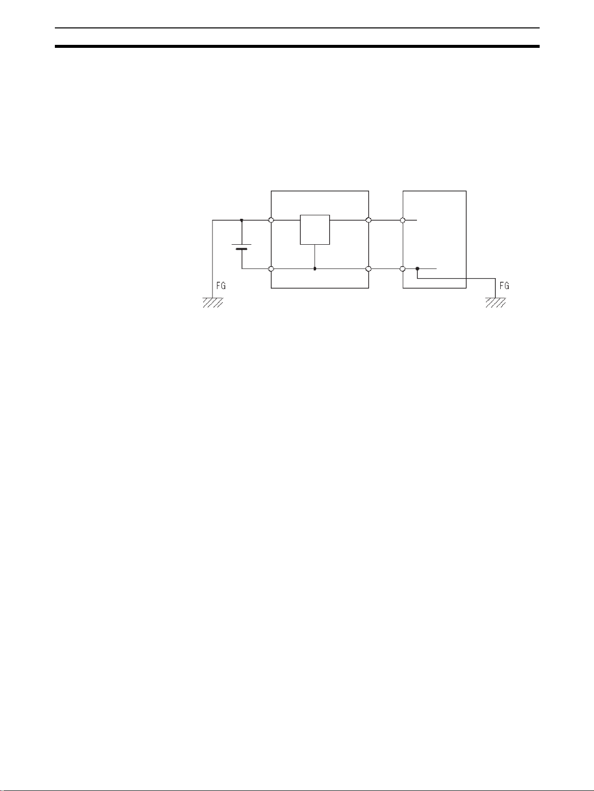
!Caution When connecting the PC t o a personal compute r or other peri pheral device,
either ground the 0-V side of the PC or do not gro und the PC a t all . Alth ough
some grounding method s shor t the 24-V side, as shown in th e following diagram, never do so with the PC.
INCORRECT Grounding: Shorting the 24-V side of the Power Supply
Non-isolated DC power
supply
24 V
0 V 0 V
PC Peripheral device
4 Operating Environment Precautions
!Caution Do not operate the control system in the following locations:
• Locations subject to direct sunlight.
• Locations subject to temperatures or humidity outside the range specified
in the specifications.
• Locations subject to condensation as the result of severe changes in temperature.
• Locations subject to corrosive or flammable gases.
• Locations subject to dust (especially iron dust) or salts.
• Locations subject to exposure to water, oil, or chemicals.
• Locations subject to shock or vibration.
!Caution Take appropriate and sufficient counter measures when installing systems in
the following locations:
0 V
• Locations subject to static electricity or other forms of noise.
• Locations subject to strong electromagnetic fields.
• Locations subject to possible exposure to radioactivity.
• Locations close to power supplies.
!Caution The operating environment of the PC System ca n have a large effect on the
longevity and reliability of the sy stem. Improper operating environme nts can
lead to malfunction, failure, and other unforeseeable problems with the PC
System. Be sure that the op erating environment is within the sp ecified cond itions at installation and remai ns within the specifi ed conditions dur ing the life
of the system.
xv
Page 15

Application Precautions 5
5 Application Precautions
Observe the following precautions when using the PC System.
!WARNING Always heed these precautions. Failure to abide by the following precautions
could lead to serious or possibly fatal injury.
• Always ground the system to 100 Ω or less when installing the Units. Not
connecting to a ground of 100 Ω or less may result in electric shock.
• Always turn OFF the power supply to the PC before attempting any of the
following. Not turning OFF the power supply may result in mal function or
electric shock.
• Mounting or dismounting Power Supply Units, I/O Units, CPU Units,
Memory Cassettes, or any other Units.
• Assembling the Units.
• Setting DIP switches or rotary switches.
• Connecting or wiring the cables.
• Connecting or disconnecting the connectors.
!Caution Failure to abide by the following precautions could lead to faulty operation of
the PC or the system, or could damage the PC or PC Units. Always heed
these precautions.
• Fail-safe measures must be taken by the customer to ensure safety in the
event of incorrect, missing, or abnorm al signals caused by broken signal
lines, momentary power interruptions, or other causes.
• Interlock circuits, limit circuits, and similar safety measures in external circuits (i.e., not in the Programmable Controller) must b e provided by the
customer.
• Always use the power supply voltage sp ecified in the manual. An incorrect voltage may result in malfunction or burning.
• Take appropriate me asures to ensure that the specified power with th e
rated voltage and frequency i s supplied. Be particula rly careful in places
where the power supply is unstable. An incorrect power supply may result
in malfunction.
• Install external breakers and take other safety measures against short-circuiting in exter nal wiring. Insufficient safety measur es against short-circuiting may result in burning.
• Do not apply voltages to the Input Units in excess of the rated input voltage. Excess voltages may result in burning.
• Do not apply voltages or connect lo ads to the Output Units in exces s of
the maximum swi tching capacity. Excess voltage or loads may r esult in
burning.
• Disconnect the functional ground terminal when performing withstand
voltage tests. Not disconnecting the functional ground terminal may result
in burning.
• Install and wire the Unit properly as specified in the manual. Improper
installation of the Unit may result in malfunction.
• Be sure that all the mounting screws , ter min al scre ws, and cable connector screws are tightened to the torque specified in the r elevant manuals.
Incorrect tightening torque may result in malfunction.
xvi
Page 16

Application Precautions 5
• Leave the label attached to the Unit when wiring. Removing the label may
result in malfunction.
• Remove the label after the completion of wiring to ensure proper heat dissipation. Leaving the label attached may result in malfunction.
• Use crimp terminals for wiring. Do not connect bare stranded wires
directly to terminals. Connection of bare stranded wires may result in
burning.
• Double-check all the wiring before turning ON the power supply. Incorrect
wiring may result in burning.
• Mount the Unit only after checking the terminal block completely.
• Be sure that the terminal bloc ks, Memory Units, expansion cables, an d
other items with locking devices are properly locked into place. Improper
locking may result in malfunction.
• Check the user program for proper execution before actually running it on
the Unit. Not checking the program may result in an unexpected operation.
• Confirm that no adverse effect will occur in the system before attemptin g
any of the following. Not doing so may result in an unexpected operation.
• Changing the operating mode of the PC.
• Force-setting/force-resetting any bit in memory.
• Changing the present value of any word or any set value in memory.
• Resume operation only after trans ferring to the new CPU Un it the contents of the DM and HR Areas required for resuming operation. Not doing
so may result in an unexpected operation.
• Do not place objects on top of the cables. Doing so may break the cables.
• Before touching the Unit, be sure to fir s t to uch a grounded metallic obj ec t
in order to discharge any static built-up. Not doing so may result in malfunction or damage.
• Do not touch the Expansion I/O Unit Connectin g Cable while the power is
being supplied in order to prevent any malfunction due to static electricity.
• When replacing parts, be sure to confirm th at the rating of a new part is
correct. Not doing so may result in malfunction or burning.
!Caution Always clear memory before beginning to program the CPM1, CPM1A or
SRM1. Although me mory is clear ed before the CPU Unit is shippe d (except
for bits with specific functi ons), AR 1314, which tur ns ON when the inter nal
capacitor cannot back up memory, may ha ve turned ON during shipment.
!Caution If the CPM1 or CPM1A will be turned OFF for periods exceeding the data
backup period of the internal capacitor, design the system so that it will not be
influenced if data in the DM, HR, and CNT area s is cleared when power is
turned OFF.
!Caution Either switch the CPM1 or CPM1 A to RUN or MONITOR mode, or turn OFF
and ON power to the CPM1 or CPM1A after chang ing from a Programming
Device any data that is backed up in flas h memory. Thi s data includes the
user program, read-only DM area (DM 6144 to DM 6599), and the PC Setup
(DM 6600 to DM 6655).
xvii
Page 17

Application Precautions 5
• The user program and memory area data in the CPM 1 or CPM1A are
backed up either by an inter nal capa citor or in f lash memory as shown i n
the following table.
Backup method Data
Internal capacitor Read/write DM area (DM 0000 to DM 0999, DM 1022, and
Flash memory User program
DM 1023)
Error log area (DM 1000 to DM 1021)
HR area (HR 00 to HR 19)
Counter area (CNT 000 to CNT 127)
Read-only DM area (DM 6144 to DM 6599)
PC Setup (DM 6600 to DM 6655)
Note
1. The IR, TR, LR, and ti mer areas are not no rmall y ba cked up when power
is turned OFF and all contents will be cleared the next time power is turned
ON. (The PC Setup s et ting in DM 660 1 c an be us ed t o ba ck up thi s data.
Refer to details on the PC Setup later in this manual for details.)
2. The bits in the AR and SR areas have special functions and are set according to these functions when power is turned ON.
• The capacitor backup time depends on the ambient temperature, as
shown in the following graph. The backup time, however, assumes that
the capacitor is fu lly charged, which requires t hat power be supplied to
the CPU Unit continuously for at least 15 minutes.
20
10
Backup time (days)
7
1
25 40 80
Ambient temperature (°C)
xviii
If the power remains OFF for a period exceeding the data backup period,
AR 1314 will turn ON to indicate that the capacitor can no longer back up data
and the data backed up by the capacitor will be cleared. AR 13 14 will rem ain
ON unless it i s tu rned OFF using I/O monitor ope rati ons, us ing m emo ry clear
operations, or from the user program.
If desired, the PC Setu p setting in DM 6604 can be set to cr eate a fatal error
and thus stop the system when AR 1314 goes ON.
• The data stored in flash memory will not be lost even if power remains
OFF for a period exceeding the data backup period, because the data
stored in flash memor y will be read to the CPU Unit when the CPM1 or
CPM1A is turned ON.
• If the power is turned OFF without changing the mode from PROGRAM
mode to RUN or MONITOR mode after having made changes in the data
that is backed up in flash memory, the changes wi ll no t be written to flas h
memory. If the power is then left OFF for more than 20 days (at 25
°C), the
Page 18

Conformance to EC Directives 6
changes (i.e., the contents of the RAM) will be erased and the data values
will become undefined.
!Caution Be sure that the SRM1 syste m is not influe nced by any undefined data if the
data in the DM, HR, or CNT area is c leare d wh en t he S RM1 ha s b een turned
OFF for a period exceeding the data backup period of the internal lithium battery. If the AR 1414 flag is ON, the dat a will be held unles s it is turne d OFF
using the I/O Monito r ope ration, in structions, etc. The s yst em can be stopped
by designating DM 6604 in the PC Setup so that a memory error occurs when
the power interruption hold area is not held (with AR 1314 ON)
• A lithium battery in the C PU Unit is used to back up the counter values
and the contents of the DM area, and HR ar ea. The deterioration of the
lithium batter y capacity depends o n the ambient temperature. T he standard service life is 12 years at an ambient temperature of 40°C when
operating 8 hours a day.
If the power remains off for a per iod exceeding the data backup per iod, the
contents of the Data Memory (DM), Hold Relay (HR), and Counter (CNT)
Areas in the CPU Un it may be cleared and the A R 1314 flag (which t urns ON
when the power interruption hold area is not held) may turn ON.
If the contents of th e CP U Un it’s program area are lo st, the pr ogram sto re d i n
flash memory will be r ead to th e CPU Unit’s program area when the SRM 1 is
started up because the contents in the read-only area (DM 6144 through
DM 6599) and PC Setup (DM 6600 through DM 6655) will be written to flash
memory.
• However, if the power is turned OFF without changing the mod e even if
changes are made in the read-only DM area (DM 6144 through DM
6599), or PC Setup (DM 6600 through DM 6655) using a peripheral
device, the contents of changes will not be written to flash memory.
Although the data in thes e areas is backed up by the lithium battery, contents of changes will disappear if the service life of the lithium battery
expires. In this case, programs in the fl ash memor y will be automa tically
read into the user program memory.
The changes can be saved by switching the SRM1 to RUN or MONITOR
mode or turning OFF and restarting the SRM1 soon after the changes are
made.
6 Conformance to EC Directives
The CQM1 PCs comp ly with EC Directives. To ensure tha t the machine or
device i n w h ich a C QM1 P C i s us ed c omp li es w i th EC D i re ct ives, the PC must
be installed as follows:
1,2,3... 1. The PC must be installed within a control panel.
2. Reinforced insulation or double insulation must be used for the DC power
supplies used for the communications and I/O power supplies.
3. PCs complying with EC Directives also conform to the Common Emission
Standard (EN50081-2). When a PC is built into a machine, however, noise
can be generated by switching devices us in g r el ay outputs and ca us e th e
overall machine to fail to meet the Stan dard. If this occurs, surge kil lers
must be connected or other measures taken external to the PC.
The following methods represent typical met hods for reduc ing noise, and
may not be sufficient in all cases. Required countermeasures will vary de-
xix
Page 19
Conformance to EC Directives 6
pending on the devices connected to the con trol pa nel , wiring, the configuration of the system, and other conditions.
Determining if Countermeasures Are Required
Refer to EN50081-2 for more details.
Countermeasur es are not required if the f requency of load switching for the
whole system including the PC is less than 5 times per minute.
Countermeasures are required if the frequency of load switching for the whole
system including the PC is more than 5 times per minute.
Countermeasure Examples
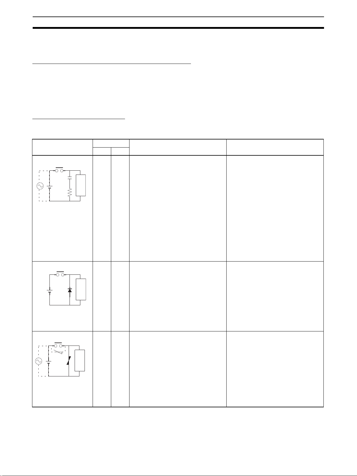
When switching an inductive load, co nne ct a n su r ge pr ot ec tor, diodes, etc., in
parallel with the load or contact as shown below.
Circuit Current Characteristic Required element
AC DC
CR method
Power
supply
Diode method
Power
supply
Varistor method
Power
supply
Yes Yes If the load is a relay or solenoid, there
is a time lag between the moment the
circuit is opened and the moment the
load is reset.
If the supply voltage is 24 or 48 V,
Inductive
load
No Yes The diode connected in parallel with
Inductive
load
Yes Yes The varistor method prevents the impo-
Inductive
load
insert the surge protector in parallel
with the load. If the supply voltage is
100 to 200 V, insert the surge protector
between the contacts.
the load changes energy accumulated
by the coil into a current, which then
flows into the coil so that the current
will be converted into Joule heat by the
resistance of the inductive load.
This time lag, b etw een the moment the
circuit is opened and the moment the
load is reset, caused by this method is
longer than that caused by the CR
method.
sition of high voltage between the contacts by using the constant voltage
characteristic of the varistor. There is
time lag between the moment the circuit is opened an d the moment the load
is reset.
If the supply voltage is 24 or 48 V,
insert the varistor in parallel with the
load. If the supply v o ltage is 100 to 2 00
V, insert the varistor between the contacts.
The capacitance of the capacitor must
be 1 to 0.5 µF per contact current of
1 A and resistance of the resistor must
be 0.5 to 1 Ω per c ontact v ol tage of 1V.
These values, however, vary with the
load and the characteristics of the
relay. Decide these values from tes ting,
and take into consideration that the
capacitance suppresses spark discharge when the contacts are separated and the resistance limits the
current that flows into the load when
the circuit is closed again.
The dielectric strength of the capacitor
must be 200 to 300 V. If the circuit is an
AC circuit, use a capacitor with no
polarity.
The reversed dielectric strength value
of the diode must be at least 10 times
as large as the circuit voltage value.
The forward current of the diode must
be the same as or larger than the load
current.
The reversed dielectric strength value
of the diode may be two to three times
larger than the supply voltage if the
surge protector is applied to electronic
circuits with low circuit voltages.
---
xx
When switching a load with a high inr ush current, such as an incandes cent
lamp, suppress the inrush current as shown below.
Page 20

Conformance to EC Directives 6
g
r
Countermeasure 1
OUT
R
COM
Providing a dark current of approx.
one-third of the rated value
throu
h an incandescent lamp
Countermeasure 2
R
OUT
COM
Providing a limiting resisto
xxi
Page 21

Conformance to EC Directives 6
xxii
Page 22

SECTION 1
PC Setup and Other Features
This section explains the PC Setup and other CQM1 /CPM1/CPM1A/SRM1 featur es, including interrupt processing and
communications. The PC Setup can be used to control the operating parameters of the CQM1/CPM1/CPM1A/SRM1. To
change the PC Setup, refer to the CQM1 Operation Manual, CPM1 Operation Manual, CPM1A Operation Manual or
SRM1 Master Control Units Operation Manual for Programming Console procedu res. Refer to the SSS O peration M anual:
C-series PCs for SSS procedures.
If you are not familiar with OMRON PCs or ladder diagram program, you can read 1-5 PC Setup as an overview of the
operating parameters available for the CQM1/CPM1/CPM1A/SRM1, but may then want to read SECTION 3 M emory
Areas, SECTION 4 Ladder-diagram Programming, and related instructions in Section SECTION 5 Instruction Set before
completing this section.
1-1 PC Setup . . . . . . . . . . . . . . . . . . . . . . . . . . . . . . . . . . . . . . . . . . . . . . . . . . . . . 3
1-1-1 Changing the PC Setup. . . . . . . . . . . . . . . . . . . . . . . . . . . . . . . . . . . 3
1-1-2 CQM1 PC Setup Settings . . . . . . . . . . . . . . . . . . . . . . . . . . . . . . . . . 4
1-1-3 CPM1/CPM1A PC Setup Settings . . . . . . . . . . . . . . . . . . . . . . . . . . 9
1-1-4 SRM1 PC Setup Settings . . . . . . . . . . . . . . . . . . . . . . . . . . . . . . . . . 13
1-2 Basic PC Operation and I/O Processes. . . . . . . . . . . . . . . . . . . . . . . . . . . . . . 16
1-2-1 Startup Mode . . . . . . . . . . . . . . . . . . . . . . . . . . . . . . . . . . . . . . . . . . 16
1-2-2 Hold Bit Status . . . . . . . . . . . . . . . . . . . . . . . . . . . . . . . . . . . . . . . . . 17
1-2-3 Program Memory Write-protection (CPM1/CPM1A Only). . . . . . . 17
1-2-4 RS-232C Port Servicing Time (CQM1/SRM1 Only). . . . . . . . . . . . 18
1-2-5 Peripheral Port Servicing Time. . . . . . . . . . . . . . . . . . . . . . . . . . . . . 18
1-2-6 Cycle Time . . . . . . . . . . . . . . . . . . . . . . . . . . . . . . . . . . . . . . . . . . . . 18
1-2-7 Input Time Constants . . . . . . . . . . . . . . . . . . . . . . . . . . . . . . . . . . . . 19
1-2-8 High-speed Timers (CQM1 Only) . . . . . . . . . . . . . . . . . . . . . . . . . . 20
1-2-9 DSW(87) Input Digits & Output Refresh Method (CQM1 On l y) . . 21
1-2-10 Error Log Settings. . . . . . . . . . . . . . . . . . . . . . . . . . . . . . . . . . . . . . . 21
1-3 Pulse Output Function (CQM1 Only). . . . . . . . . . . . . . . . . . . . . . . . . . . . . . . 22
1-3-1 Types of Pulse Outputs. . . . . . . . . . . . . . . . . . . . . . . . . . . . . . . . . . . 22
1-3-2 Standard Pulse Output from an Output Point. . . . . . . . . . . . . . . . . . 23
1-3-3 Standard Pulse Output from Ports 1 and 2 . . . . . . . . . . . . . . . . . . . . 25
1-3-4 Variable-duty-ratio Pulse Output from Ports 1 and 2 . . . . . . . . . . . . 32
1-3-5 Determining the Status of Ports 1 and 2. . . . . . . . . . . . . . . . . . . . . . 34
1-4 Pulse Output Function (CPM1A Only). . . . . . . . . . . . . . . . . . . . . . . . . . . . . . 35
1-4-1 Programming Example in Continuous Mode. . . . . . . . . . . . . . . . . . 36
1-4-2 Programming Example in Independent Mode . . . . . . . . . . . . . . . . . 36
1-4-3 Using Pulse Output Instructions. . . . . . . . . . . . . . . . . . . . . . . . . . . . 36
1-4-4 Changing the Frequency. . . . . . . . . . . . . . . . . . . . . . . . . . . . . . . . . . 37
1-4-5 Stopping Pulse Output . . . . . . . . . . . . . . . . . . . . . . . . . . . . . . . . . . . 37
1-5 CQM1 Interrupt Functions . . . . . . . . . . . . . . . . . . . . . . . . . . . . . . . . . . . . . . . 38
1-5-1 Types of Interrupts . . . . . . . . . . . . . . . . . . . . . . . . . . . . . . . . . . . . . . 38
1-5-2 Input Interrupts . . . . . . . . . . . . . . . . . . . . . . . . . . . . . . . . . . . . . . . . . 40
1-5-3 Masking All Interrupts . . . . . . . . . . . . . . . . . . . . . . . . . . . . . . . . . . . 44
1-5-4 Interval Timer Interrupts. . . . . . . . . . . . . . . . . . . . . . . . . . . . . . . . . . 45
1-5-5 High-speed Counter 0 Interrupts . . . . . . . . . . . . . . . . . . . . . . . . . . . 47
1-5-6 High-speed Counter 0 Overflows/Underflows . . . . . . . . . . . . . . . . . 53
1-5-7 High-spee d Counter 1 and 2 Interrupts (CQM1-CPU43-EV1) . . . . 55
1-5-8 Absolute High-speed Counter Interrupts (CQM1-CPU44-EV1). . . 62
1
Page 23

1-6 CPM1/CPM1A Interrupt Functions. . . . . . . . . . . . . . . . . . . . . . . . . . . . . . . . . 67
1-6-1 Types of Interrupts. . . . . . . . . . . . . . . . . . . . . . . . . . . . . . . . . . . . . . . 67
1-6-2 Input Interrupts . . . . . . . . . . . . . . . . . . . . . . . . . . . . . . . . . . . . . . . . . 69
1-6-3 Masking All Interrupts . . . . . . . . . . . . . . . . . . . . . . . . . . . . . . . . . . . 74
1-6-4 Interval Timer Interrupts . . . . . . . . . . . . . . . . . . . . . . . . . . . . . . . . . . 75
1-6-5 High-speed Counter Interrupts . . . . . . . . . . . . . . . . . . . . . . . . . . . . . 77
1-7 SRM1 Interrupt Functions. . . . . . . . . . . . . . . . . . . . . . . . . . . . . . . . . . . . . . . . 85
1-7-1 Types of Interrupts. . . . . . . . . . . . . . . . . . . . . . . . . . . . . . . . . . . . . . . 85
1-7-2 Interval Timer Interrupts . . . . . . . . . . . . . . . . . . . . . . . . . . . . . . . . . . 85
1-8 CompoBus/S Distributed I/O Functions (SRM1 Only). . . . . . . . . . . . . . . . . . 88
1-9 Communications Functions. . . . . . . . . . . . . . . . . . . . . . . . . . . . . . . . . . . . . . . 89
1-9-1 CQM1 PC Setup . . . . . . . . . . . . . . . . . . . . . . . . . . . . . . . . . . . . . . . . 90
1-9-2 Wiring Ports . . . . . . . . . . . . . . . . . . . . . . . . . . . . . . . . . . . . . . . . . . . 93
1-9-3 CQM1 Host Link Communications . . . . . . . . . . . . . . . . . . . . . . . . . 93
1-9-4 CPM1/CPM1A Host Link Communications. . . . . . . . . . . . . . . . . . . 95
1-9-5 SRM1 Host Link Communications. . . . . . . . . . . . . . . . . . . . . . . . . . 97
1-9-6 RS-232C Communications (CQM1/SRM1 Only) . . . . . . . . . . . . . . 100
1-9-7 CQM1 One-to-one Link Communications . . . . . . . . . . . . . . . . . . . . 102
1-9-8 CPM1/CPM1A One-to-one Link Communications . . . . . . . . . . . . . 104
1-9-9 CPM1/CPM1A NT Link Communications. . . . . . . . . . . . . . . . . . . . 1 05
1-9-10 SRM1 One-to-one Link Communications . . . . . . . . . . . . . . . . . . . . 106
1-9-11 SRM1 NT Link Communications. . . . . . . . . . . . . . . . . . . . . . . . . . . 108
1-9-12 SRM1 No Protocol Communications . . . . . . . . . . . . . . . . . . . . . . . . 109
1-9-13 Tr ansmission Data Configuration . . . . . . . . . . . . . . . . . . . . . . . . . . . 111
1-9-14 Tr ansmission Flags . . . . . . . . . . . . . . . . . . . . . . . . . . . . . . . . . . . . . . 112
1-9-15 No Protocol Communications Program Example. . . . . . . . . . . . . . . 112
1-10 Calculating with Signed Binary Data . . . . . . . . . . . . . . . . . . . . . . . . . . . . . . . 113
1-10-1 Definition of Signed Binary Data . . . . . . . . . . . . . . . . . . . . . . . . . . . 113
1-10-2 Arithmetic Flags . . . . . . . . . . . . . . . . . . . . . . . . . . . . . . . . . . . . . . . . 115
1-10-3 Inputting Signed Binary Data Using Decimal Values. . . . . . . . . . . . 115
1-10-4 Using Signed-binary Expansion Instructions (CQM1 Only) . . . . . . 115
1-10-5 Application Example Using Signed Binary Data . . . . . . . . . . . . . . . 116
2
Page 24

PC Setup Section 1-1
1-1 PC Setup
The PC Setup compr ises various operating parameters that contro l CQM1/
CPM1/CPM1A/SRM1 operation. In order to make the maximum use of
CQM1/CPM1/CPM1A/SRM1 functionality when using interrupt processing
and communications fu nctions, the PC Setup may be customized accor ding
to operating conditions.
At the time of shipping, the defaults are set for general operating conditions,
so that the CQM1/CPM1/CPM1A/SRM1 can be used without having to
change the settings. You are, however, advised to check the default values
before operation.
Default Values The default values for the PC Setup are 0000 for all words. The default values
can be reset at any time by turning ON SR 25210.
!Caution When data memory (DM) is cleared from a Programming Device, the PC
Setup settings will also be cleared to all zeros.
1-1-1 Changing the PC Setup
PC Setup settings are accessed at various times depending on the setting, as
described below.
• DM 6600 to DM 6614: Accessed only when PC’s power supply is turned
on.
• DM 6615 to DM 6644: Accessed only when program execution begins.
• DM 6645 to DM 6655: Accessed regularly when the power is on.
Since changes in the PC Setup become effective only at the times given
above, the CQM1/CPM1/CPM1A/SRM1 will have to be restarted to make
changes in DM 6600 to DM 6614 effective, and program execution will have to
be restarted to make changes in DM 6615 to DM 6644 effective.
When DM 6602 bits 00 to 03 are set to protect the program memory , DM 6602
cannot be changed using the PC Setup operation of the Support Software. To
change DM 6602, use the I/O Monitor or DM Edit operation.
Making Changes from a
Peripheral Device
The PC Setup can be read, but not wr itten into, from the user program. Writing can be done only by using a Programming Device.
Although the PC Se tup is stored in DM 6600 to DM 665 5, settings can be
made and changed only from a Programming Device (e.g., SSS, or Programming Console). DM 6600 to DM 6644 can be set or changed only while in
PROGRAM mode. DM 6645 to DM 6655 can be set or changed while in either
PROGRAM mode or MONITOR mode.
The following settings can be made in PROGRAM mode from the SSS us ing
menu operations. All other se ttin gs must b e ma de u sing th e hexadeci ma l s etting operation.
• Startup Mode (DM 6600)
• I/O Hold Bit Status and Forced Status Hold Bit Status (DM 6601)
• Cycle Monitor Time (DM 6618)
• Cycle Time (DM 6619)
• RS-232C Port Settings (DM 6645 to DM 6649)
Note The RS-232C Port Setti ngs (DM 6645 to DM 6649) are no t used in CPM1/
CPM1A PCs because these PCs aren’t equipped with an RS-232C port.
3
Page 25

PC Setup Section 1-1
Errors in the PC Setup If an incorrect PC Setup settin g is acc essed, a non-fatal error (er ror code 9B)
will be generated, the c orresponding error flag (AR 2400 to AR 2402 in th e
CQM1, AR 1300 to AR 1302 in the CPM1/ CPM1A/SRM1) wil l be turned ON ,
and the default setting will be used instead of the incorrect setting.
1-1-2 CQM1 PC Setup Settings
The PC Setup is broadly divided into four categories: 1) Settings rela ted to
basic CQM1 operation and I/O proces ses, 2) Settin gs related to pulse o utput
functions, 3) Settings re lated to in terr upts, and 4) Set tings related t o communications. This section wi ll explain the settings according to these classifications.
The following table shows the setting in order in the DM area. For details, refer
to the page numbers shown.
Word(s) Bit(s) Function Page
Startu p Processing (DM 6600 to DM 6614)
The following settings are effective after transfer to the PC only after the PC is restarted.
DM 6600 00 to 07 Startup mode (effective when bits 08 to 15 are set to 02).
00: PROGRAM; 01: MONITOR 02: RUN
08 to 15 Startup mode designation
00: Programming Console switch
01: Continue operating mode last used before power was turned off
02: Setting in 00 to 07
DM 6601 00 to 07 Not used.
08 to 11 IOM Hold Bit (SR 25212) Status
0: Reset; 1: Maintain
12 to 15 Forced Status Hold Bit (SR 25211) Status
DM 6602 to
DM 6610
DM 6611 00 to 15 CQM1-CPU43-EV1: Mode setting for ports 1 and 2
DM 6612 00 to 15 CQM1-CPU44-EV1: Origin compensation setting for port 2 (4-digit BCD) 63
Pulse Output and Cycle Time Settings (DM 6615 to DM 6619)
The following settings are effective after transfer to the PC the next time operation is started.
DM 6615 00 to 07 Word for pulse output.
DM 6616 00 to 07 Servicing time for RS-232C port (effective when bits 08 to 15 are set to 01)
DM 6617 00 to 07 Servicing time for peripheral port (effective when bits 08 to 15 are set to 01)
DM 6618 00 to 07 Cycle monitor time (effective when bits 08 to 15 are set to 01, 02, or 03)
00 to 15 Not used.
08 to 15 Not used.
08 to 15 RS-232C port servicing setting enable
08 to 15 Peripheral port servicing setting enable
08 to 15 Cycle monitor enable (Setting in 00 to 07 x unit; 99 s max.)
0: Reset; 1: Maintain
0000: High-speed counter mode; 0001: Pulse output mode
CQM1-CPU44-EV1: Origin compensation setting for port 1 (4-digit BCD)
00: IR 100; 01: IR101; 02: IR 102... 15: IR 115
00 to 99 (BCD): Percentage of cycle time used to service RS-232C port.
00: 5% of the cycle time
01: Use time in 00 to 07.
00 to 99 (BCD): Percentage of cycle time used to service peripheral.
00: 5% of the cycle time
01: Use time in 00 to 07.
00 to 99 (BCD): Setting (see 08 to 15)
00: 120 ms (setting in bits 00 to 07 disabled)
01: Setting unit: 10 ms
02: Setting unit: 100 ms
03: Setting unit: 1 s
16
17
25, 63
24
18
18
21
4
Page 26

PC Setup Section 1-1
Word(s) Bit(s) Function Page
DM 6619 00 to 15 Cycle time
0000: Variable (no minimum)
0001 to 9999 (BCD): Minimum time in ms
Interrupt Processing (DM 6620 to DM 6639)
The following settings are effective after transfer to the PC the next time operation is started.
DM 6620 00 to 03 Input constant for IR 00000 to IR 00007
0: 8 ms; 1: 1 ms; 2: 2 ms; 3: 4 ms; 4: 8 ms; 5: 16 ms; 6: 32 ms; 7: 64 ms; 8: 128 ms
04 to 07 Input constant for IR 00008 to IR 00015 (Setting same as bits 00 to 03)
08 to 15 Input constant for IR 001
00: 8 ms; 01: 1 ms; 02: 2 ms ; 03 : 4 m s; 04: 8 ms; 05: 16 ms; 06: 32 ms; 07: 64 ms; 08:
128 ms
DM 6621 00 to 07 Input constant for IR 002 (Setting same as for IR 001.)
08 to 15 Input constant for IR 003 (Setting same as for IR 001.)
DM 6622 00 to 07 Input constant for IR 004 (Setting same as for IR 001.)
08 to 15 Input constant for IR 005 (Setting same as for IR 001.)
DM 6623 00 to 07 Input constant for IR 006 (Setting same as for IR 001.)
08 to 15 Input constant for IR 007 (Setting same as for IR 001.)
DM 6624 00 to 07 Input constant for IR 008 (Setting same as for IR 001.)
08 to 15 Input constant for IR 009 (Setting same as for IR 001.)
DM 6625 00 to 07 Input constant for IR 010 (Setting same as for IR 001.)
08 to 15 Input constant for IR 011 (Setting same as for IR 001.)
DM 6626 00 to 07 Input constant for IR 012 (Setting same as for IR 001.)
08 to 15 Input constant for IR 013 (Setting same as for IR 001.)
DM 6627 00 to 07 Input constant for IR 014 (Setting same as for IR 001.)
08 to 15 Input constant for IR 015 (Setting same as for IR 001.)
DM 6628 00 to 03 Interrupt enable for IR 00000 (0: Normal input; 1: Interrupt input) 40
04 to 07 Interrupt enable for IR 00001 (0: Normal input; 1: Interrupt input)
08 to 11 Interrupt enable for IR 00002 (0: Normal input; 1: Interrupt input)
12 to 15 Interrupt enable for IR 00003 (0: Normal input; 1: Interrupt input)
DM 6629 00 to 07 Number of high-speed timers for interrupt refreshing
00 to 15 (BCD; e.g., set 15 for 00 to 14)
08 to 15 High-speed timer interrupt refresh enable
00: 16 timers (setting in bits 00 to 07 disabled)
01: Use setting in 00 to 07
DM 6630 00 to 07 First input refresh word for I/O interrupt 0: 00 to 11 (BCD) 40
08 to 15 Number of input refresh words for I/O interrupt 0: 00 to 12 (BCD)
DM 6631 00 to 07 First input refresh word for I/O interrupt 1: 00 to 11 (BCD)
08 to 15 Number of input refresh words for I/O interrupt 1: 00 to 12 (BCD)
DM 6632 00 to 07 First input refresh word for I/O interrupt 2: 00 to 11 (BCD)
08 to 15 Number of input refresh words for I/O interrupt 2: 00 to 12 (BCD)
DM 6633 00 to 07 First input refresh word for I/O interrupt 3: 00 to 11 (BCD)
08 to 15 Number of input refresh words for I/O interrupt 3: 00 to 12 (BCD)
DM 6634 00 to 07 First input refresh word for high-speed counter 1: 00 to 11 (BCD) 40
08 to 15 Number of input refresh words for high-speed counter 1: 00 to 12 (BCD)
DM 6635 00 to 07 First input refresh word for high-speed counter 1: 00 to 11 (BCD) 40
08 to 15 Number of input refresh words for high-speed counter 1: 00 to 12 (BCD)
18
19
20
5
Page 27

PC Setup Section 1-1
Word(s) Bit(s) Function Page
DM 6636 00 to 07 First input refresh word for interval timer 0: 00 to 07 (BCD) 45, 50
08 to 15 Number of input refresh words for interval timer 0: 00 to 08 (BCD)
DM 6637 00 to 07 First input refresh word for interval timer 1: 00 to 07 (BCD)
08 to 15 Number of input refresh words for interval timer 1: 00 to 08 (BCD)
DM 6638 00 to 07 First input refresh word for interval timer 2 (also used for high-speed counter 0): 00 to
08 to 15 Number of input refresh words for interval timer 2: 00 to 08 (BCD)
DM 6639 00 to 07 Output refresh method
08 to 15 Number of digits for DIGITAL SWITCH (DSW(87)) instruction
High-speed Counter Settings (DM 6640 to DM 6644)
The following settings are effective after transfer to the PC the next time operation is started.
DM 6640,
DM 6641
DM 6642 00 to 03 High-speed counter 0 mode
DM 6643 00 to 03 CQM1-CPU43-EV1: Port 1 input setting
DM 6644 00 to 15 Port 2 settings (Identical to the port 1 settings in DM 6643.)
00 to 15 Not used.
04 to 07 High-speed counter 0 reset mode
08 to 15 High-speed counter 0 enable
04 to 07 CQM1-CPU43-EV1: Por t 1 reset setting
08 to 11 CQM1-CPU43-EV1: Por t 1 counting mode setting
12 to 15 CQM1-CPU43-EV1: Por t 1 pulse type setting
07 (BCD)
(also used for high-speed counter 0)
21, 393
00: Cyclic; 01: Direct
21, 124
00: 4 digits; 01: 8 digits
50
0: Up/down counter mode; 4: Incrementing counter mode
0: Z phase and software reset; 1: Software reset only
00: Don’t use high-speed counter; 01: Use high-speed counter with settings in 00 to 07
55, 62
0: Differential phase input; 1: Pulse/Direction input; 2: Up/Down input
CQM1-CPU44-EV1: Port 1 input setting
0: 8-bit input; 1: 10-bit input; 2: 12-bit input
57
0: Z phase and software reset; 1: Software reset only
CQM1-CPU44-EV1: Not used. Set to 0.
56, 62
0: Linear mode; 1: Ring mode
CQM1-CPU44-EV1: Port 1 mode setting
0: BCD mode; 1: 360° mode
25, 32
0: Standard pulse output (0.5 duty ratio); 1: Variable-duty-ratio pulse output
CQM1-CPU44-EV1: Not used. Set to 0.
6
Page 28

PC Setup Section 1-1
Word(s) Bit(s) Function Page
RS-232C Port Settings
The following settings are effective after transfer to the PC.
DM 6645 00 to 07 Port settings
00: Standard (1 start bit, 7-bit data, even parity, 2 stop bits, 9,600 bps)
01: Settings in DM 6646
08 to 11 Link words for 1:1 link (Effective when bits 12 to 15 are set to 3.)
0: LR 00 to LR 63; 1: LR 00 to LR 31; 2: LR 00 to LR 15
12 to 15 Communications mode
0: Host link; 1: RS-232C (no protocol); 2: 1:1 data link slave; 3: 1:1 data link master;
4: NT Link (1:1) (NT Link setting is only applicable to the CQM1-CPU4@-EV1 CPU
Units.)
DM 6646 00 to 07 Baud rate
00: 1.2K, 01: 2.4K, 02: 4.8K, 03: 9.6K, 04: 19.2K
08 to 15 Frame format
Start Length Stop Parity
00: 1 bit 7 bits 1 bit Even
01: 1 bit 7 bits 1 bit Odd
02: 1 bit 7 bits 1 bit None
03: 1 bit 7 bits 2 bit Even
04: 1 bit 7 bits 2 bit Odd
05: 1 bit 7 bits 2 bit None
06: 1 bit 8 bits 1 bit Even
07: 1 bit 8 bits 1 bit Odd
08: 1 bit 8 bits 1 bit None
09: 1 bit 8 bits 2 bit Even
10: 1 bit 8 bits 2 bit Odd
11: 1 bit 8 bits 2 bit None
DM 6647 00 to 15 Transmission delay (Host Link)
0000 to 9999 (BCD): Set in units of 10 ms, e.g., setting of 0001 equals 10 ms
DM 6648 00 to 07 Node number (Host link, effective when bits 12 to 15 of DM 6645 are set to 0.)
00 to 31 (BCD)
08 to 11 Start code enable (RS-232C, effective when bits 12 to 15 of DM 6645 are set to 1.)
0: Disable; 1: Set
12 to 15 End code enable (RS-232C, effective when bits 12 to 15 of DM 6645 are set to 1.)
0: Disable (number of bytes received)
1: Set (specified end code)
2: CR, LF
DM 6649 00 to 07 Start code (RS-232C)
00 to FF (binary)
08 to 15 When bits 12 to 15 of DM 6648 are set to 0:
Number of bytes received
00: Default setting (256 bytes)
01 to FF: 1 to 255 bytes
When bits 12 to 15 of DM 6648 are set to 1:
End code (RS-232C)
00 to FF (binary)
90
90
7
Page 29

PC Setup Section 1-1
Word(s) Bit(s) Function Page
Peripheral Port Settings
The following settings are effective after transfer to the PC.
These settings are effective when a CQM1-CIF01 Connecting Cable is used.
They are not effective when a CQM1-CIF11 Connecting Cable or Programming Console is used.
DM 6650 00 to 07 Port settings
00: Standard (1 start bit, 7-bit data, even parity, 2 stop bits, 9,600 bps)
01: Settings in DM 6651
08 to 11 Not used.
12 to 15 Communications mode
0: Host link; 1: RS-232C
DM 6651 00 to 07 Baud rate
00: 1.2K, 01: 2.4K, 02: 4.8K, 03: 9.6K, 04: 19.2K
08 to 15 Frame format
Start Length Stop Parity
00: 1 bit 7 bits 1 bit Even
01: 1 bit 7 bits 1 bit Odd
02: 1 bit 7 bits 1 bit None
03: 1 bit 7 bits 2 bit Even
04: 1 bit 7 bits 2 bit Odd
05: 1 bit 7 bits 2 bit None
06: 1 bit 8 bits 1 bit Even
07: 1 bit 8 bits 1 bit Odd
08: 1 bit 8 bits 1 bit None
09: 1 bit 8 bits 2 bit Even
10: 1 bit 8 bits 2 bit Odd
11: 1 bit 8 bits 2 bit None
DM 6652 00 to 15 Transmission delay (Host Link)
0000 to 9999: In ms.
DM 6653 00 to 07 Node number (Host link, effective when bits 12 to 15 of DM 6650 are set to 0.)
00 to 31 (BCD)
08 to 11 Start code enable (RS-232C, effective when bits 12 to 15 of DM 6650 are set to 1.)
0: Disable; 1: Set
12 to 15 End code enable (RS-232C, effective when bits 12 to 15 of DM 6650 are set to 1.)
0: Disable (number of bytes received)
1: Set (specified end code)
2: CR, LF
DM 6654 00 to 07 Start code (RS-232C, effective when bits 08 to 11 of DM 6653 are set to 1.)
00 to FF (binary)
08 to 15 When bits 12 to 15 of DM 6653 are set to 0:
Number of bytes received
00: Default setting (256 bytes)
01 to FF: 1 to 255 bytes
When bits 12 to 15 of DM 6653 are set to 1:
End code (RS-232C)
00 to FF (binary)
90
90
Error Log Settings (DM 6655)
The following settings are effective after transfer to the PC.
DM 6655 00 to 03 Style
0: Shift after 10 records have been stored
1: Store only first 10 records (no shifting)
2 to F: Do not store records
04 to 07 Not used.
08 to 11 Cycle time monitor enable
0: Detect long cycles as non-fatal err ors
1: Do not detect long cycles
12 to 15 Low battery error enable
0: Detect low battery voltage as non-fatal error
1: Do not detect low batter voltage
8
22
22
Page 30

PC Setup Section 1-1
1-1-3 CPM1/CPM1A PC Setup Settings
The PC Setup is broadly divided into four categories: 1) Settings rela ted to
basic PC operation and I/O processes, 2) Settings related to the cycle time, 3)
Settings related to inter r upt s, and 4) S ettings re la ted to c ommun icati ons. This
section will explain the settings according to these classifications.
The following table shows the settings for CPM1/CPM1A PCs in o rder. Refer
to the page number in the last column for more details on that setting.
Word(s) Bit(s) Function Page
Startu p Processing (DM 6600 to DM 6614)
The following settings are effective after transfer to the PC only after the PC is restarted.
DM 6600 00 to 07 Startup mode (effective when bits 08 to 15 are set to 02).
08 to 15 Startup mode designation
DM 6601 00 to 07 Not used. 17
08 to 11 IOM Hold Bit (SR 25212) Status at Startup
12 to 15 Forced Status Hold Bit (SR 25211) Status at Startup
DM 6602 00 to 03 Program memory write-protection
04 to 07 Programming Console display language
08 to 15 Not used.
DM 6603 00 to 15 Not used.
DM 6604 00 to 07 00: If data could not be saved with the built-in capacitor (AR 1314 ON), a memory error will not
08 to 15 Not used.
DM 6605 to
DM 6614
Cycle Time Settings (DM 6615 to DM 6619)
The following settings are effective after transfer to the PC the next time operation is started.
DM 6615,
DM 6616
DM 6617 00 to 07 Servicing time for peripheral port (effective when bits 08 to 15 are set to 01)
DM 6618 00 to 07 Cycle monitor time (effective when bits 08 to 15 are set to 01, 02, or 03)
DM 6619 00 to 15 Cycle time
00 to 15 Not used.
00 to 15 Not used.
08 to 15 Peripheral port servicing setting enable
08 to 15 Cycle monitor enable (Setting in 00 to 07 x unit; 99 s max.)
00: PROGRAM; 01: MONITOR 02: RUN
00: Programming Console switch
01: Continue operating mode last used before power was turned off. (See note 1.)
02: Setting in 00 to 07
0: Reset; 1: Maintain (See note 3.)
0: Reset; 1: Maintain (See note 3.)
0: Program memory unprotected
1: Program memory write-protected (except DM 6602 itself)
0: English; 1: Japanese
be generated.
01: If data could not be saved with the built-in capacitor (AR 1314 ON), a memory error will be
generated.
00 to 99 (BCD): Percentage of cycle time used to service peripheral.
00: 5% of the cycle time
01: Use time in 00 to 07.
00 to 99 (BCD): Setting (see 08 to 15)
00: 120 ms (setting in bits 00 to 07 disabled)
01: Setting unit: 10 ms
02: Setting unit: 100 ms
03: Setting unit: 1 s
0000: Variable (no minimum)
0001 to 9999 (BCD): Minimum time in ms
16
17
18
21
18
9
Page 31

PC Setup Section 1-1
Word(s) Bit(s) Function Page
Interrupt Processing (DM 6620 to DM 6639)
The following settings are effective after transfer to the PC the next time operation is started.
DM 6620 00 to 03 Input constant for IR 00000 to IR 00002
04 to 07 Input constant for IR 00003 and IR 00004 (Setting same as bits 00 to 03)
08 to 11 Input constant for IR 00005 and IR 00006 (Setting same as bits 00 to 03)
12 to 15 Input constant for IR 00007 and IR 00011 (Setting same as bits 00 to 03)
DM 6621 00 to 07 Input constant for IR 001
08 to 15 Input constant for IR 002 (Setting same as for IR 001.)
DM 6622 00 to 07 Input constant for IR 003 (Setting same as for IR 001.)
08 to 15 Input constant for IR 004 (Setting same as for IR 001.)
DM 6623 00 to 07 Input constant for IR 005 (Setting same as for IR 001.)
08 to 15 Input constant for IR 006 (Setting same as for IR 001.)
DM 6624 00 to 07 Input constant for IR 007 (Setting same as for IR 001.)
08 to 15 Input constant for IR 008 (Setting same as for IR 001.)
DM 6625 00 to 07 Input constant for IR 009 (Setting same as for IR 001.)
08 to 15 Not used.
DM 6626 to
DM 6627
DM6628 00 to 03 Interrupt enable for IR 00003 (0: Normal input; 1: Interrupt input; 2: Quick-response) 40
DM 6629 to
DM 6641
High-speed Counter Settings (DM 6640 to DM 6644)
The following settings are effective after transfer to the PC the next time operation is started.
DM 6640 to
DM 6641
DM 6642 00 to 03 High-speed counter mode
DM 6643,
DM 6644
00 to 15 Not used.
04 to 07 Interrupt enable for IR 00004 (0: Normal input; 1: Interrupt input; 2: Quick-response)
08 to 11 Interrupt enable for IR 00005 (0: Normal input; 1: Interrupt input; 2: Quick-response)
12 to 15 Interrupt enable for IR 00006 (0: Normal input; 1: Interrupt input; 2: Quick-response)
00 to 15 Not used. 40
00 to 15 Not used.
04 to 07 High-speed counter reset mode
08 to 15 High-speed counter enable
00 to 15 Not used.
0: 8 ms; 1: 1 ms; 2: 2 ms; 3: 4 ms; 4: 8 ms; 5: 16 ms; 6: 32 ms; 7: 64 ms; 8: 128 ms
00: 8 ms; 01: 1 ms; 02: 2 ms; 03: 4 ms; 04: 8 ms; 05: 16 ms ; 06: 32 ms; 07: 64 ms ; 08:
128 ms
0: Up/down counter mode; 4: Incrementing counter mode
0: Z phase and software reset; 1: Software reset only
00: Don’t use high-speed counter; 01: Use high-speed counter with settings in 00 to 07
19
50
10
Page 32

PC Setup Section 1-1
Word(s) Bit(s) Function Page
Peripheral Port Settings
The following settings are effective after transfer to the PC.
DM 6645 to
DM 6649
DM 6650 00 to 07 Port settings
DM 6651 00 to 07 Baud rate
DM 6652 00 to 15 Transmission delay (Host Link) (See note 4.)
DM 6653 00 to 07 Node number (Host link)
DM 6654 00 to 15 Not used.
Error Log Settings (DM 6655)
The following settings are effective after transfer to the PC.
DM 6655 00 to 03 Style
00 to 15 Not used. 90
00: Standard (1 start bit, 7-bit data, even parity, 2 stop bits, 9,600 bps)
01: Settings in DM 6651
(Other settings will cause a non-fatal error and AR 1302 will turn ON.)
08 to 11 Link area for one-to-one PC link via peripheral port:
0: LR 00 to LR 15
12 to 15 Communications mode
0: Host link; 2: One-to-one PC link (slave); 3: One-to-one PC link (master); 4: NT Link
(Other settings will cause a non-fatal error and AR 1302 will turn ON.)
00: 1.2K, 01: 2.4K, 02: 4.8K, 03: 9.6K, 04 : 19.2K, 0 5 to 07 : Cannot b e used (see note 2)
(Other settings will cause a non-fatal error and AR 1302 will turn ON.)
08 to 15 Frame format
Start Length Stop Parity
00: 1 bit 7 bits 1 bit Even
01: 1 bit 7 bits 1 bit Odd
02: 1 bit 7 bits 1 bit None
03: 1 bit 7 bits 2 bit Even
04: 1 bit 7 bits 2 bit Odd
05: 1 bit 7 bits 2 bit None
06: 1 bit 8 bits 1 bit Even
07: 1 bit 8 bits 1 bit Odd
08: 1 bit 8 bits 1 bit None
09: 1 bit 8 bits 2 bit Even
10: 1 bit 8 bits 2 bit Odd
11: 1 bit 8 bits 2 bit None
(Other settings will cause a non-fatal error and AR 1302 will turn ON.)
0000 to 9999: In ms.
(Other settings will cause a non-fatal error and AR 1302 will turn ON.)
00 to 31 (BCD)
(Other settings will cause a non-fatal error and AR 1302 will turn ON.)
08 to 15 Not used.
22
0: Shift after 7 records have been stored
1: Store only first 7 records (no shifting)
2 to F: Do not store records
04 to 07 Not used.
08 to 11 Cycle time monitor enable
0: Detect long cycles as non-fatal err ors
1: Do not detect long cycles
12 to 15 Not used.
Note 1. When the startup mode is set to continue the operating mode last used be-
fore the power was turned off, that operatin g mo de wil l be r et ain ed by the
built-in capacitor. If the power remains off for longer than the backup time
of the capacitor, the data may be lost. (For details on the holding time, refer
to the CPM1A or CPM1 Operation Manual.)
11
Page 33

PC Setup Section 1-1
2. Do not set to “05” to “07.” If set to this value , the CPM1/CPM1A will not operate properly and the RUN PC Setup Error Flag (AR 1302 O N) will not
turn ON.
3. Retention of IOM Hold Bit (SR 25212) Status
If the “IOM Hold Bit Status at Startup” (D M 6601, bits 08 to 11) is set to
“Maintain” with the IOM Hold Bit (SR 25212) turned ON, operation can be
started w ith the I/O m emor y (I/O, IR, LR) status j ust as it was before the
power was turned OFF. ( The input area is ref reshed at star tup, however,
so it is overwritten by the most recently updated input status.)
Retention of Forced Status Hold Bit (SR 25211) Status
If the “Forced Status Hold Bit Status at Startup” (DM 6601, bits 12 to 15) is
set to “Maintain” with the Forced Status Hold Bit (SR 2521 1) turned O N,
operation can be star ted with the forced set/reset status ju st as it was before the power was turned OFF. (When starting up in RUN Mode, however,
the forced set/reset status is cleared.)
Even if the “IOM Hold Bit Status at Startup” or “Forced Status Hold Bit Status at Startup” is set to “Maintain,” the IOM Hold Bit (SR 25212) or Forced
Status Hold Bit (SR 25211) status may be cleared if the power remains
OFF for longer than the b ackup time of the built-i n capacitor. (For details
on the holding t ime, refer to the CPM1A or CPM1 Operation Manual.) At
this time the I/O memory will also be cleared, so set up the system so that
clearing the I/O memory will not cause problems.
4. The transmission delay is the delay between the previous transmission
and the next transmission.
Host computer
Programmable Controller
Command
Command
Response
Transmission delay time
Response
5. If an out-of-range value is set, the following communications conditions will
result. In that case, reset the value so that it is within the permissible range.
Communications mode: Host Link
Communications format: Standard settings
(1 start bit, 7-bit data; even parity, 2 stop bits,
9,600 bps)
Transmission delay: No
Node number: 00
12
Page 34

PC Setup Section 1-1
1-1-4 SRM1 PC Setup Settings
The PC Setup is broadly divided into three categor ies: 1) Settings rel ated to
basic PC operation and I/O pr ocesses, 2) Settings related to the cycle time,
and 3) Settings related to co mmunications. This section will explain the settings according to these classifications.
The following table shows the settings for SRM1 PCs in order. Refer to the
page number in the last column for more details on that setting.
Word(s) Bit(s) Function Page
Startu p Processing (DM 6600 to DM 6614)
The following settings are effective after transfer to the PC only after the PC is restarted.
DM 6600 00 to 07 Startup mode (effective when bits 08 to 15 are set to 02).
08 to 15 Startup mode designation
DM 6601 00 to 07 Not used. 17
08 to 11 IOM Hold Bit (SR 25212) Status
12 to 15 Forced Status Hold Bit (SR 25211) Status
DM 6602 00 to 03 Program memory write-protection
04 to 07 Programming Console display language
08 to 11 Expansion Instructions
12 to 15 Not used.
DM 6603 00 to 03 Maximum number of CompoBus/S devices
04 to 15 Not used.
DM 6604 00 to 07 00: If data could not be sa ved for a po w e r i nterrupti on (AR 1314 ON), a memory error will not be
08 to 15 Not used.
DM 6605 to
DM 6614
Cycle Time Settings (DM 6615 to DM 6619)
The following settings are effective after transfer to the PC the next time operation is started.
DM 6615 00 to 15 Not used.
DM 6616 00 to 07 Servicing time for RS-232C port (effective when bits 08 to 15 are set)
DM 6617 00 to 07 Servicing time for peripheral port (effective when bits 08 to 15 are set to 01)
00 to 15 Not used.
08 to 15 RS-232C port servicing enable
08 to 15 Peripheral port servicing setting enable
00: PROGRAM; 01: MONITOR 02: RUN
00: Programming Console switch
01: Continue operating mode last used before power was turned off
02: Setting in 00 to 07
0: Reset; 1: Maintain (See caution on page page 17.)
0: Reset; 1: Maintain
0: Program memory unprotected
1: Program memory write-protected (except DM 6602 itself)
0: English; 1: Japanese
0: Default settings; 1: User settings
0: Max. no. 32
1: Max. no. 16
generated.
01: If data could not be saved for a power interruption (AR 1314 ON), a memory error will be
generated.
00 to 99 (BCD): Percentage for cycle time used to service peripheral.
00: 5% of the cycle time
01: Use time in 00 to 07.
00 to 99 (BCD): Percentage of cycle time used to service peripheral.
00: 5% of the cycle time
01: Use time in 00 to 07.
16
17
18
18
13
Page 35

PC Setup Section 1-1
Word(s) Bit(s) Function Page
DM 6618 00 to 07 Cycle monitor time (effective when bits 08 to 15 are set to 01, 02, or 03)
08 to 15 Cycle monitor enable (Setting in 00 to 07 x unit; 99 s max.)
DM 6619 00 to 15 Cycle time
DM 6620 to
DM 6644
RS-232C Port Settings
The following settings are effective after transfer to the PC.
DM 6645 00 to 03 Port settings
DM 6646 00 to 07 Baud rate
DM 6647 00 to 15 Transmission delay (Host Link)
DM 6648 00 to 07 Node number (Host link, effective when bits 12 to 15 of DM 6645 ar e set to 0.)
DM 6649 00 to 07 Start code (RS-232C)
00 to 15 Not used.
04 to 07 CTS control settings
08 to 11 Link words for 1:1 link
12 to 15 Communications mode
08 to 15 Frame format
08 to 11 Start code enable (RS-232C, effective when bits 12 to 15 of DM 6645 are set to 1.)
12 to 15 End code enable (RS-232C, effective when bits 12 to 15 of DM 6645 are set to 1.)
08 to 15 When bits 12 to 15 of DM 6648 are set to 0:
00 to 99 (BCD): Setting (see 08 to 15)
00: 120 ms (setting in bits 00 to 07 disabled)
01: Setting unit: 10 ms
02: Setting unit: 100 ms
03: Setting unit: 1 s
0000: Variable (no minimum)
0001 to 9999 (BCD): Minimum time in ms
0: Standard (1 start bit, 7-bit data, even parity, 2 stop bits, 9,600 bps)
1: Settings in DM 6646
0: Disable; 1: Set
0: LR 00 to LR 15; Other: Not effective
0: Host link; 1: RS-232C (no protocol); 2: 1:1 data link slave; 3: 1:1 data link master;
4: NT Link
00: 1.2K, 01: 2.4K, 02: 4.8K, 03: 9.6K, 04: 19.2K
Start Length Stop Parity
00: 1 bit 7 bits 1 bit Even
01: 1 bit 7 bits 1 bit Odd
02: 1 bit 7 bits 1 bit None
03: 1 bit 7 bits 2 bit Even
04: 1 bit 7 bits 2 bit Odd
05: 1 bit 7 bits 2 bit None
06: 1 bit 8 bits 1 bit Even
07: 1 bit 8 bits 1 bit Odd
08: 1 bit 8 bits 1 bit None
09: 1 bit 8 bits 2 bit Even
10: 1 bit 8 bits 2 bit Odd
11: 1 bit 8 bits 2 bit None
0000 to 9999 (BCD): Set in units of 10 ms, e.g., setting of 0001 equals 10 ms
00 to 31 (BCD)
0: Disable; 1: Set
0: Disable (number of bytes received)
1: Set (specified end code)
2: CR, LF
00 to FF (binary)
Number of bytes received
00: Default setting (256 bytes)
01 to FF: 1 to 255 bytes
When bits 12 to 15 of DM 6648 are set to 1:
End code (RS-232C)
00 to FF (binary)
21
18
97
97
14
Page 36

PC Setup Section 1-1
Word(s) Bit(s) Function Page
Peripheral Port Settings
The following settings are effective after transfer to the PC.
DM 6650 00 to 03 Port settings
00: Standard (1 start bit, 7-bit data, even parity, 2 stop bits, 9,600 bps)
01: Settings in DM 6651
(Other settings will cause a non-fatal error and AR 1302 will turn ON.)
04 to 07 Not used.
08 to 11 Not used.
12 to 15 Communications mode
0: Host link; 1: No protocol
(Other settings will cause a non-fatal error and and AR 1302 will turn ON.)
DM 6651 00 to 07 Baud rate
00: 1.2K, 01: 2.4K, 02: 4.8K, 03: 9.6K, 04: 19.2K
08 to 15 Frame format
Start Length Stop Parity
00: 1 bit 7 bits 1 bit Even
01: 1 bit 7 bits 1 bit Odd
02: 1 bit 7 bits 1 bit None
03: 1 bit 7 bits 2 bit Even
04: 1 bit 7 bits 2 bit Odd
05: 1 bit 7 bits 2 bit None
06: 1 bit 8 bits 1 bit Even
07: 1 bit 8 bits 1 bit Odd
08: 1 bit 8 bits 1 bit None
09: 1 bit 8 bits 2 bit Even
10: 1 bit 8 bits 2 bit Odd
11: 1 bit 8 bits 2 bit None
(Other settings will cause a non-fatal error and AR 1302 will turn ON.)
DM 6652 00 to 15 Transmission delay (Host Link)
0000 to 9999 (BCD): Set in units of 10 ms.
(Other settings will cause a non-fatal error and AR 1302 will turn ON.)
DM 6653 00 to 07 Node number (Host link)
00 to 31 (BCD)
(Other settings will cause a non-fatal error and AR 1302 will turn ON.)
08 to 11 Start code enable (RS-232C, effective when bits 12 to 15 of DM6650 are set to 1.)
0: Disable
1: Set
12 to 15 End code enable (RS-232C, effective when bits 12 to 15 of DM6650 are set to 1.)
0: Disable (number of bytes received)
1: Set (specified end code)
2: CR, LF
DM 6654 00 to 07 Start code (effective when bits 08 to 11 of DM6650 are set to 1.)
00: 256 bytes
01 to FF: 1 to 255 bytes
08 to 15 End code
When bits 12 to 15 of DM6653 are set to 0:
00: 256 bytes
01 to FF: 1 to 255 bytes
When bits 12 to 15 of DM6653 are set to 1:
Setting: 00 to FF (binary)
97
15
Page 37

Basic PC Operation and I/O Processes Section 1-2
Word(s) Bit(s) Function Page
Error Log Settings (DM 6655)
The following settings are effective after transfer to the PC.
DM 6655 00 to 03 Style
0: Shift after 7 records have been stored
1: Store only first 7 records
Errors will not be stored if other values are set.
04 to 07 Not used.
08 to 11 Cycle time monitor enable
0: Detect long cycles as non-fatal err ors
1: Do not detect long cycles
12 to 15 Not used.
Note If an out-of-range value is set, the following co mmunications con ditions will
result. In that case, reset the value so that it is within the permissible range.
Communications mode: Host Link
Communications format: Standard settings
(1 start bit, 7-bit data; even parity, 2 stop bits,
9,600 bps)
Transmission delay: No
Node number: 00
22
1-2 Basic PC Operation and I/O Processes
This section explains the PC Setup settings related to basic operation and I/O
processes.
1-2-1 Startup Mode
The operation mode the PC will start in when power is turned on can be set as
shown below.
Startup Mode Designation
00: Programming Console Mode Selector (If not connected: RUN mode)
01: Operating mode last used before power was turned off
02: Mode set in bits 00 to 07
Startup Mode (Bits 08 to 15: Valid when bits 00 to 07 are set to 02)
00: PROGRAM mode
01: MONITOR mode
02: RUN mode
Default: Programming Console Mode Selector or RUN mode when Programming
Console is not connected.
Bit
DM6600
15
0
16
Page 38

Basic PC Operation and I/O Processes Section 1-2
1-2-2 Hold Bit Status
Make the settings shown below to determine whether, when the power supply
is turned on, the Forced Status Hold Bit (SR 25211) and/or IOM Hold Bit
(SR 25212) will retai n the status that was in effect when the power was last
turned off, or whether the previous status will be cleared.
15 0
Bit
DM6601
0 0
SR 25211 setting
0: Clear status
1: Retain status
SR 25212 setting
0: Clear status
1: Retain status
Default: Clear both.
Always 00
The Forced Status Hold Bit (SR 25211) de ter mines whether or not the forced
set/reset status is r etained when chang ing from PROGRAM mode to MONITOR mode.
The IOM Hold Bit (SR 25212) dete rmin es whether or not the status of IR bits
and LR bits is retained when PC operation is started and stopped.
!Caution Do not use the I/O Hold Bit Status and Forced Status Hold Bit Status Bits
(DM 6601) when the power to the PC is going to be turned off longer than the
memory backup time of the in ternal capacitor. If the memory backup time is
exceeded, memory status will b e unstable even if the I/O H old B it S tatus and
Forced Status Hold Bit Status Bi ts are used. Unpr edic table results may occur
if operation is attempted with unstable memory status.
Note 1. The memory backup time of the internal capacitor varies with the ambient
temperature, but is 20 days at 25
°C. Refer to hardware specifications for
more details.
2. The memory backup time assumes that the internal capacitor is fully
charged before power is turned off. Fulling charging the capacitor requires
that power is supplied to the CPU Unit for at least 15 minutes.
1-2-3 Program Memory Write-protection (CPM1/CPM1A Only)
In CPM1/CPM1A PCs the program m emory can be p rotected by setting bits
00 to 03 of DM 6602 to 0. Bits 04 to 07 determine whether Programming Console messages are displayed in English or Japanese.
15 0
Bit
DM6602
Programming Console messages
0: English
1: Japanese
Program memory
0: Not write-protected
1: Write-protected
Default: English displays, not write-protected
Note DM 6602 itself can still be changed after the program memory has been write-
protected by setting bits 04 to 07 of DM 6602 to 1.
0 0
Always 00
17
Page 39

Basic PC Operation and I/O Processes Section 1-2
y
y
1-2-4 RS-232C Port Servicing Time (CQM1/SRM1 Only)
The following settings are used to determi ne the perc entage of the cy cle time
devoted to servicing the RS-232C port.
15 0
Bit
DM6616
Servicing time setting enable
00: Disabled (5% used)
01: Enabled (setting in bits 00 to 07 used)
Servicing time (%, valid with bits 08 to 15 are 01)
00 to 99 (BCD, two digits)
Default: 5% of c
Example: If DM 6616 is set to 0110, the RS-232C por t will be serviced for
10% of the cycle time.
The servicing time will be 0.34 ms minimum.
The entire servicing time will not be used unless processing requests exist.
1-2-5 Peripheral Port Servicing Time
The following settings are used to determi ne the perc entage of the cy cle time
devoted to servicing the peripheral port.
Servicing time setting enable
00: Disabled (5% used)
01: Enabled (setting in bits 00 to 07 used)
Servicing time (%, valid with bits 08 to 15 are 01)
00 to 99 (BCD, two digits)
Default: 5% of c
Example: If DM 6617 is set to 0115, the periphe ral port will be serviced for
15% of the cycle time.
The servicing time will be 0.34 ms minimum.
The entire servicing time will not be used unless processing requests exist.
cle time
cle time
15 0
Bit
DM6617
1-2-6 C ycle Time
18
Make the settings shown below to standardi ze the cyc le time and t o elim inat e
variations in I/O response time by setting a minimum cycle time.
15 0
Bit
DM6619
Cycle time (4 digits BCD)
0000:Cycle time variable
0001 to 9999: Minimum cycle time (Unit: 1 ms)
Default: Cycle time variable
If the actual cycle time is shor ter tha n the minimum cycle tim e, execution will
wait until the minimum time has expired. If the actual cycle time is longer than
Page 40

Basic PC Operation and I/O Processes Section 1-2
0
)
the minimum cycle time, then operation will proceed according to the actual
cycle time. AR 2405 will turn ON if the minimum cycle time is exceeded.
1-2-7 Input Time Constants
Make the settings shown below to set the time from when the actua l inputs
from the DC Input Unit are tur ned ON or OFF until the correspondi ng input
bits are updated (i.e., until th eir ON/O FF status is changed ). Make these settings when you want to adjust the time until inputs stabilize.
Increasing the inpu t time const ant ca n redu ce the effects from ch atter ing and
external noise.
Input from an input device
such as a limit switch
Input bit status
tt
The SRM1 does not have this setting.
CQM1 PCs DM 6620 contains the input time constants for both IR 000 and IR 001.
Input Time Constants for IR 000 and IR 001
Input time constant
15
Bit
DM 6620
Time constant for IR 001 (2 digits BCD; see below.)
Time constant for IR 00008 to IR 00015 (1 digit BCD; see below.)
Time constant for IR 00000 to IR 00007 (1 digit BCD; see below.)
Default: 0000 (8 ms for each
Input Time Constants for IR 002 to IR 015
DM 6621: IR 002 and IR 003
DM 6622: IR 004 and IR 005
DM 6623: IR 006 and IR 007
DM 6624: IR 008 and IR 009
DM 6625: IR 010 and IR 011
DM 6626: IR 012 and IR 013
DM 6627: IR 014 and IR 015
Time constant for IR 003, IR 005, IR 007, IR 009, IR 011, IR 013, and IR 015
Time constant for IR 002, IR 004, IR 006, IR 008, IR 010, IR 012, and IR 014
Default: 0000 (8 ms for each)
DM 6621 to DM 6627
15 0
Bit
The nine possible set tings for the input time const ant are shown below. Set
only the rightmost digit for IR 000.
0: 8 ms 1: 1 ms 2: 2 ms 3: 4 ms 4: 8 ms
5: 16 ms 6: 32 ms 7: 64 ms 8: 128 ms
19
Page 41

Basic PC Operation and I/O Processes Section 1-2
0
)
g
CPM1/CPM1A PCs Set the input time constants for CPM1/CPM1A inputs from a Peripheral
Device.
Input Time Constants for IR 000
15
Bit
Time constant for IR 00007 to IR 00011 (1 digit BCD; see below.)
Time constant for IR 00005 to IR 00006 (1 digit BCD; see below.)
Time constant for IR 00003 to IR 00004 (1 digit BCD; see below.)
Time constant for IR 00000 to IR 00002 (1 digit BCD; see below.)
Default: 0000 (8 ms for each
Input Time Constants for IR 001 to IR 009
DM 6621: IR 001 and IR 002
DM 6622: IR 003 and IR 004
DM 6623: IR 005 and IR 006
DM 6624: IR 007 and IR 008
DM 6625: IR 009
Time constant for IR 002, IR 004, IR 006, and IR 008
Time constant for IR 001, IR 003, IR 005, IR 007, and IR 009
Default: 0000 (8 ms for each)
DM 6621 to DM 6625
DM 6620
Bit
15 0
The nine possible set tings for the input time const ant are shown below. Set
only the rightmost digit for IR 000.
0: 8 ms 1: 1 ms 2: 2 ms 3: 4 ms 4: 8 ms
5: 16 ms 6: 32 ms 7: 64 ms 8: 128 ms
The CPM1/CPM1A’s I/O response time is the input time constant (1 ms to
128 ms; default is 8 ms) + the cycle time.
Refer to 7-2 CPM1/CPM1A Cycle Time and I/O Response Time for more
details.
1-2-8 High-speed Timers (CQM1 Only)
Make the settings shown below t o set the number of high-speed timers created with TIMH(15) that will use interrupt processing.
High-speed timer interrupt setting enable
00: Setting disabled (Interrupt processing for all high-speed timers, TIM 000 to TIM 015)
01: Enabled (Use setting in bits 00 to 07.)
Number of high-speed timer for interrupts (valid when bits 08 to 15 are 01)
00 to 15 (2 digits BCD)
Default: Interrupt processin
15 0
Bit
DM6629
for all high-speed timers,TIM 000 to TIM 015.
20
The setting indicates the number of timers that will use interrupt processing
beginning with TIM 000. For example, if “0108” is specified, then eigh t timers,
TIM 000 to TIM 007 will use interrupt processing.
Note High-speed timers will not be accurate without interrupt processing unless the
cycle time is 10 ms or less.
Page 42

Basic PC Operation and I/O Processes Section 1-2
Interrupt response time for other interrupts will be improved if interrup t processing is set to 0 0 when high-speed timer pr ocessing is not required. This
includes any time the cycle time is less than 10 ms.
Note If the SPED(64) i nstruction is used an d pulses are output at a frequency of
500 Hz or greater, then set the number of high-speed timers with interrupt
processing to four or less. Refer to information on the SPED(64) instruction for
details.
1-2-9 DSW(87) Input Digits & Output Refresh Method (CQM1 Only)
Make the settings shown below to set the number of input di git s the DSW (87)
instruction, and to set the output refresh method.
15 0
Bit
DM 6639
Number of input digits for the DSW(87)
00: 4 digits
01: 8 digits
Output refresh method
00: Cyclic
01: Direct
Refer to SECTION 2 Special Features for details on the DSW (87) instr uction
and to SECTION 7 PC Operations and Processing Time for details on I/O
refresh methods.
1-2-10 Error Log Settings
Make the settings shown below for detecting errors and storing the error log.
Cycle Monitor Time (DM 6618)
The cycle monitor time is used for checking for extremely long cy c le time s, as
can happen when the program goes into an infinite loop. If the cycle time
exceeds the cycle monitor setting, a fatal error (FALS 9F) will be generated.
Default: The number of input digits for the DSW(87) instruction is set to "4" and the output refresh method is cyclic.
15 0
Bit
DM6618
Cycle Monitor Time Enable and Unit
00: Setting disabled (time fixed at 120 ms)
01: Setting in 00 to 07 enabled; unit:10 ms
02: Setting in 00 to 07 enabled; unit:100 ms
03: Setting in 00 to 07 enabled; unit:1 s
Cycle monitor time setting (When bits 08 to 15 are not 00)
00 to 99 (2 digits BCD; unit set in bits 08 to 15.)
Note 1. The unit used for the maximum and current cycle times recorded in the AR
area (AR 26 and AR 27 in the CQM1, AR 14 and AR 15 in t he CPM1/
CPM1A/SRM1) depend on the unit set for the cycle monitor time in
DM 6618, as shown below.
Bits 08 to 15 set to 01: 0.1 ms
Bits 08 to 15 set to 02: 1 ms
Bits 08 to 15 set to 03: 10 ms
21
Page 43

Pulse Output Function (CQM1 Only) Section 1-3
2. If the cycle time is 1 s or longer, the cycle time read from Programming Devices will be 999.9 m s. The co rrect m aximum and c urrent cycl e time s will
be recorded in the AR area.
Example
If 0230 is set in DM 6618, an FALS 9F error will not occur un til the cyc le tim e
exceeds 3 s. If the actual cycle time is 2 .59 s, the cur rent cycl e time st ored i n
the AR area will be 2590 (ms), but the cycle tim e read from a Programming
Device will be 999.9 ms.
A “cycle time over” error (non-fatal) will be generated when the cycle time
exceeds 100 ms unless detection of long cy cle ti mes is di sable using the setting in DM 6655.
Error Detection and Error Log Operation (DM 6655)
Make the settings shown be low to deter mi ne whether o r not a non-fatal error
is to be generated when the cycle time exceeds 100 ms or when the voltag e
of the built-in battery drops (CQM1 only), and to set the method for storin g
records in the error log when errors occur.
15 0
Bit
DM6655
0
Low battery voltage detection
0: Detect
1: Don't detect
Cycle time over detection
0: Detect
1: Don't detect
Error log storage method
0: Error records for 10 (CQM1) or 7 (SRM1/CPM1/CPM1A) most recent errors always stored (older errors deleted).
1: Only first 10 (CQM1) or 7 (SRM1/CPM1/CPM1A) error records stored (no errors
stored beyond that point).
2 to F: Error records not stored.
Default: Low battery voltage and cycle time over errors detected, and error records
stored for the 10 most recent errors.
Battery errors and cycle time overrun errors are non-fatal errors.
For details on the error log, refer to SECTION 8 Troubleshooting.
Note The low battery error is applicable to CQM1 only. This digit isn’t used in
CPM1/CPM1A/SRM1 PCs.
1-3 Pulse Output Function (CQM1 Only)
This section explains the settings and methods for using the CQM1 pulse output function. Refer to the CQM1 Operation Ma nual for details on hardware
connections to output points and ports.
Always
0
1-3-1 Types of Pulse Outputs
All of the CQM1 PCs can output standa rd pulses from an out put bit and the
CQM1-CPU43-EV1 can also output standard or variable-duty-ratio pulses
from por ts 1 and 2. Standard puls e outputs have a duty ra tio (t
The duty ratio for variable-duty-ratio pulse outputs can be set from 1% to 99%
in 1% increments.
Note With the CQM1-CPU43-EV1, the pulse outputs described below can be out-
put from three por ts simultaneo usly. Further more, two por ts can be used for
counter inputs independent of the pulse output.
22
/T) of 50%.
on
Page 44

Pulse Output Function (CQM1 Only) Section 1-3
Standard Pulse Output
from an Output Point
Standard pulses (duty ratio = 5 0%) can be o utput f rom an outp ut poi nt wi th a
frequency from 20 Hz to 1 kHz. The I/O word is specified in the PC Setup and
the bit is specified in the pulse output instruction itself.
Refer to page 23 for more details.
Standard Pulse Output
from Ports 1 and 2
With the CQM1-CPU 43-EV1, standa rd pulses (duty ratio = 50%) c an be output from port 1 and/ or 2 w ith a f re que ncy from 10 Hz to 50 k Hz ( 20 kH z max.
to a stepping motor). The pulse output can be either clockwise (CW) or
counter-clockwise (CCW) and frequency changes can be made smoothly.
PLS2(––) and mode 0 of ACC(––) cannot be used when the PC Setup
(DM 6611) is set to high-s pee d co unter mode. CTBL(63) canno t be u se d wit h
ports 1 and 2 when the PC Setup (DM 6611) is set to pulse output mode.
Refer to page 25 for more details.
Variable-duty-ratio Pulse
Output from Ports 1 and 2
With the CQM1-CPU43-EV1, variable-duty-ratio pulses (duty ratio = 0% to
99%) can be output from port 1 and/or 2 with frequencies of 91.6 Hz, 1.5 kHz,
or 5.9 kHz. Only one direction can be output and the pulse output will continue
until stopped with INI(61).
Refer to page 32 for more details.
1-3-2 Standard Pulse Output from an Output Point
Standard pulses c an be output from a specified output bit using SPED(64).
Pulses can be output from just one bit at a time. The following diagram shows
the pulses being output from the output point of the Transistor Output Unit
mounted on a CQM1 PC. The duty ratio o f the pulse output is 50% and th e
frequency can be set from 20 Hz to 1 kHz.
Transistor Output Unit
t
on
= 50% (0.5)
T
t
on
T
Note 1. A Transistor Output Unit must be used for this application.
2. Pulses cannot be output when interval timer 0 is operating.
3. When a pulse o utput high er than 500 Hz is be ing o utput, set the number
of high-speed timers with interr upt proces sing to 4 by sett ing DM 662 9 to
0104.
When outputting p ulses from an output p oint, the fr equency can be changed
in steps by executing SPED(64) again with different fr equen cies, as s hown in
the following diagram.
Frequency
Time
There are two ways to stop the pulse output:
1,2,3... 1. After executing SPED(64), the pulse ou tput wil l s to p i f INI(61 ) is executed
with C=003 or SPED(64) is executed again with the frequency set to 0.
23
Page 45

Pulse Output Function (CQM1 Only) Section 1-3
p
2. The total number of pulses that will be output can be set with PULS(65) before execution of SPED(64). In this case, SPED(64 ) must be executed in
independent mode. The pulse outp ut stops automatica lly when the number of pulses set by PULS(65) have been output.
Note Refer to the sections on SPE D(64) and PULS(65) for more de tails on these
instructions.
PC Setup Settin gs Before executing SPED(64) to output pulses from an Output Un it, set th e PC
to PROGRAM mode and make the following settings in the PC Setup.
In DM 6615, specify the output word that will be used for SPED(64) pulse out-
put to Output Units. (The bit is specified in the first operand in SPED(64).)
The content of DM 6615 (0000 to 0011) specifies output words IR 100 to
IR 111. For example, if DM 6615 is set to 0002, pulses will be output to
IR 102.
15 0
Bit
DM6615
Output word (rightmost 2 digits, BCD): 00 to 11
0 0
Always 00
Default: Pulse out
ut to IR 100.
In the CQM1-CPU11/21-E CPUs, set dire ct output refre shing in DM 6639, as
shown below. (In CQM1-CPU4@-EV1 CPU Units the output refresh method
can be set to either direct or cyclic.)
15 0
Bit
DM 6639
Output refresh method
01: Direct
Default: The default output refresh method is cyclic.
0 1
Continuous Pulse Output Pulses will be gin to be output at the specifie d output bit when SPED(64) is
executed. Set the output bit from 00 to 15 ( D=000 to 150) an d the frequen cy
from 20 Hz to 1000 Hz (F=0002 to 0100). S et the mode to continuous mode
(M=001).
Execution condition
@SPED(64)
D
M
F
The pulse output can be s topped by executing INI(61) with C=003 or executing SPED(64) again with the frequency set to 0. The frequency can be
changed by executing SPED(64) again with a different frequency setting.
Setting the Number of
Pulses
24
The total number of pulses that will be output can be set with PULS(65) before
executing SPED(64) in independent mode. The pulse output will stop au tomatically when the number of pulses set by PULS(65) have been output.
Execution condition
@PULS(65)
000
000
P1
Page 46

Pulse Output Function (CQM1 Only) Section 1-3
PULS(65) sets the 8-digit number of pulses P1+1, P1. These pulses ca n be
set from 00000001 to 167772 15. The number of pulses set wi th PULS(65) is
accessed when SPED (64) is executed in independent mode. (The number of
pulses cannot be changed for pulses that are being output.)
Execution condition
@SPED(64)
D
M
F
When SPED(64) is executed, pulses wi ll begin to be output at the s pecified
output bit (D=000 to 150: bi t 00 to 15) at the sp ecified frequency (F=0002 to
0100: 20 Hz to 1000 Hz). Set the mode to independe nt mode (M=001) to output the number of pulses se t with PULS(65 ). The frequenc y can be cha nged
by ex ecuting SPED(64) again with a different frequency setting.
Changing the Frequency T he frequency of the pulse output can be changed by executing SPED(64)
again with a different frequency setting. Use the same output bit (P) and mode
(M) settings that were us ed to start the pul se output . The new frequ ency can
be frequency 20 Hz to 1000 Hz (F=0002 to 0100).
1-3-3 Standard Pulse Output from Ports 1 and 2
With the CQM1-CPU43-EV1, s tand ar d pul se s can be output from por ts 1 and
2 using SPED(64), P LS2(––), or ACC(––). The pulse frequency c an be set
from 10 Hz to 50 kHz (20 kHz max. to a stepping motor). The pulse output can
be either clockwise (CW) or counter-clockwise (CCW) and frequency changes
can be made smoothly.
CPU Unit
t
on
= 50% (0.5)
T
t
Port 1
Port 2
CW
CCW
CW
CCW
on
T
Note Only the CQM1-CPU43-EV1 CPU Unit can output pulses from ports 1 and 2.
When outputting pulse s from a por t, the freq uency can be cha nged smooth ly
or in steps with SPED(64), PLS2(––) , and ACC(––), as shown in the following
diagram.
Frequency
Time
There are two ways to stop the pulse output:
1,2,3... 1. After executing SPED(64), the pulse ou tput wil l s to p i f INI(61 ) is executed
with C=003 or SPED(64) is executed again with the frequency set to 0.
25
Page 47

Pulse Output Function (CQM1 Only) Section 1-3
g
2. The total number of pulses that will be output can be set with PULS(65) before execution of SPED(64). In this case, SPED(64 ) must be executed in
independent mode. The pulse outp ut stops automatica lly when the number of pulses set by PULS(65) have been output.
The following table shows the types of frequency ch anges that can be made
with combinations of PULS(65), SPED(64), INI(61), PLS2(––), and ACC(––).
Frequency change Instruction Operand settings Page
Start pulse output at the specified frequency.
Outputs continuously or until the specified
number of pulses have been output.
(Execute PULS(65) and then SPED(64).)
Stop pulse output with an instruction.
(Execute SPED(64) or INI(61).)
Outputs a specified number of pulses.
Accelerates pulse output to the target fre-
quency at the specified rate. Decelerates at
the same rate.
Outputs a specified number of pulses.
Accelerates pul se ou tput to target frequency
1 at the specified rate. Decelerates to target
frequency 2 at another rate.
(Execute PULS(65) and then ACC(––).)
Accelerates pulse output from the current
frequency to the target frequency at the
specified rate.
Pulse output will continue.
(Execute PULS(65) and then ACC(––).)
Decelerates pulse output from the current
frequency to the target frequency at the
specified rate.
Pulse output will stop when the specified
number of pulses have been output.
(Execute PULS(65) and then ACC(––).)
Decelerates pulse output from the current
frequency to the target frequency at the
specified rate.
Pulse output will continue.
(Execute PULS(65) and then ACC(––).)
PULS(65) CW/CCW
SPED(64) Port
SPED(64) Port
INI(61) Control word=0
PLS2(––) Port
PULS(65) CW/CCW
ACC(––)
(Mode 0)
PULS(65) CW/CCW 30
ACC(––)
(Mode 1)
PULS(65) CW/CCW
ACC(––)
(Mode 2)
PULS(65) CW/CCW 31
ACC(––)
(Mode 3)
(Number of pulses)
Mode
Frequency
Frequency= 0
CW/CCW
Acceleration rate
Target frequency
Number of pulses
Number of pulses
Deceleration point
Port
Acceleration rate
Target frequency 1
Deceleration rate
Target frequency 2
Port
Acceleration rate
Target frequency
Number of pulses
Port
Deceleration rate
Target frequency
Port
Deceleration rate
Target frequency
27
28
29
30
31
PC Setup Settin gs Before outputting pulses from port 1 or 2, switch the P C to PROGRAM mode
and make the following settings in the PC Setup.
In DM 6611, specify the mode setting for ports 1 and 2.
15 0
Bit
DM 6611
Port 1 and 2 Mode Setting
0000: High-speed counter mode
0001: Pulse output mode
Default: The default mode settin
01
is high-speed counter mode.
26
Page 48

Pulse Output Function (CQM1 Only) Section 1-3
Some instructions cannot be used depending on the mode setting in DM
6611.
DM 6611 setting Affected instructions
High-speed counter mode (0000) PLS2(––) and mode 0 of ACC (––) cannot be
used.
Pulse output mode (0001) CTBL(63) cannot be used with ports 1 and 2.
The setting in DM 6611 is read only when the CQM1 is star ted . If this settin g
is changed, be sure to turn the PC off and then on again to make the new setting effective.
Specify standard pulse outputs in DM 6643 (port 1) and/or DM 6644 (port 2).
Example 1:
Starting Pulse Output with
PULS(65) and SPED(64)
Bit
DM 6643
15 0
0
Port 1 pulse type setting
0: Standard pulse output
Default: Standard pulse output
DM 6644
15 0
Bit
0
Port 2 pulse type setting
0: Standard pulse output
Default: Standard pulse output
Variable-duty-ratio pulses cannot be outp ut from a por t if it has been set for
standard pulse output in DM 6643 or DM 6644.
The following example shows PULS(65) and SPED(64) used to control a
pulse output from port 1. The number of pulses specified in PULS(65)
(10,000) are output as the frequ ency is changed by executions of SPED(64)
with different frequency settings.
Before executing the pro gram make sure that DM 6611 is set to 0001 (puls e
output mode) and DM 6643 is set to 0000 (standard pulse setting for port 1).
05000
00000
00001
00002
@PULS(65)
001
000
DM 0000
@SPED(64)
001
000
#0100
@SPED(64)
001
000
#0150
@SPED(64)
001
000
#0100
@SPED(64)
001
000
#0050
When 05000 goes ON, PULS(65) sets port 1 for 10,000 CW
pulses.
Starts pulse output from port 1 at 1 kHz in independent
mode.
When 00000 goes ON, the frequency from port 1 is
changed to 1.5 kHz.
When 00001 goes ON, the frequency from port 1 is
changed to 1 kHz.
When 00002 goes ON, the frequency from port 1 is
changed to 500 Hz.
27
Page 49

Pulse Output Function (CQM1 Only) Section 1-3
The following diagram shows the frequency of pulse ou tputs from port 1 as
the program is executed.
Frequency
1.5 kHz
1.0 kHz
0.5 kHz
Time
05000
goes ON
!Caution Be sure that the pulse fr equency is withi n the motor’s self-star ting frequen cy
range when starting and stopping the motor.
Note Speed control timing wil l be very accurate when fr equency changes are per-
formed as input interrupt processes.
00000
goes ON
00001
goes ON
00002
goes ON
10,000
pulses
Example 2: Stopping
Pulse Output with
SPED(64)
The following example shows PULS(65) and SPED(64) used to control a
pulse output from port 1. The frequency is changed by executions of
SPED(64) with different frequency settings and finally stopped with a frequency setting of 0.
05000
00005
00006
00007
@PULS(65)
001
004
000
@SPED(64)
001
001
#0100
@SPED(64)
001
001
#0150
@SPED(64)
001
001
#0100
@SPED(64)
001
001
#0000
When 05000 goes ON, PULS(65) sets port 1 for CW pulse
output. There is no number of pulses setting.
Starts pulse output from port 1 at 1 kHz in continuous mode.
When 00005 goes ON, the frequency from port 1 is
changed to 1.5 kHz.
When 00006 goes ON, the frequency from port 1 is
changed to 1 kHz.
When 00007 goes ON, the pulse output from port 1 is
stopped with a frequency setting of 0 Hz.
28
Page 50

Pulse Output Function (CQM1 Only) Section 1-3
-
g
g
The following diagram shows the frequency of pulse ou tputs from port 1 as
the program is executed.
Frequency
1.5 kHz
1.0 kHz
Time
05000
goes ON
!Caution Be sure that the pulse fr equency is withi n the motor’s self-star ting frequen cy
range when starting and stopping the motor.
Example 3: PLS2(– –) The following example shows PLS2(– –) used to output 100,000 CW pulses
from port 1. The frequency is accelerated to 1 0 k Hz at app roximately 50 0 Hz /
4 ms and decelerated at the same rate.
Five seconds after the CW pulses have been output, another PLS2(––)
instruction outputs 100,000 CCW pulses with the same settings.
DM 0000 0050
DM 0001 1000
DM 0002 0000
DM 0003 0010
00005
goes ON
00006
goes ON
00007
goes ON
00000
05000
AR 0514
TIM 000
SET 05000
@PLS2(––)
001
000
DM 0000
TIM 000
#0050
@PLS2(––)
001
001
DM 0000
RSET 05000 05000 is turned OFF when TIM 000 times out.
05000 is turned ON when 00000 is ON.
When 05000 goes ON, PLS2(––) star ts CW pulse output
from port 1.
Acceleration rate: Approx. 500 Hz/4 ms
Target frequency: 10 kHz
Number of pulses: 100,000
A 5 s timer is started when AR 0514 (the Pulse Output Com
pleted flag) is ON.
When TIM 000 times out, PLS2(––) star ts CCW pulse output from port 1.
Acceleration rate: Approx. 500 Hz/4 ms
Target frequency: 10 kHz
Number of pulses: 100,000
The following diagram shows the frequency of pulse ou tputs from port 1 as
the program is executed.
Frequency
10 kHz
CW pulse output CCW pulse output
05000
oes ON
AR 0514
oes ON
After 5 s
About 500 Hz/4 ms
Time
29
Page 51

Pulse Output Function (CQM1 Only) Section 1-3
g
Example 4 :ACC(––)
Mode 0
The following example shows mode 0 of ACC(––) used to output 10,000 CW
pulses from por t 1. The fr equency is ac celerated to 10 k Hz at approximately
1 kHz/4 ms and decelerated to 1 kHz at approximately 250 Hz/4 ms. Deceleration begins after 9,100 pulses have been output.
DM 0000 0000
DM 0001 0001
DM 0002 9100
DM 0003 0000
00000
DM 0004 0100
DM 0005 1000
DM 0006 0025
DM 0007 0050
@PULS(65)
001
002
DM 0000
@ACC(––)
001
000
DM 0004
When 00000 goes ON, PULS(65) sets port 1 for CW pulse
output. The total number of pulses is set to 10,000 and the
deceleration point is set to 9,100 pulses.
Starts CW pulse output from port 1.
Acceleration rate: Approx. 1000 Hz/4 ms
Frequency after acceleration: 10 kHz
Deceleration rate: Approx. 250 Hz/4 ms
Frequency after deceleration: 1 kHz
The following diagram shows the frequency of pulse ou tputs from port 1 as
the program is executed.
Frequency
Example 5: ACC(––)
Mode 1
10 kHz
About 250 Hz/4 ms
About 1 kHz/4 ms
1 kHz
00000
oes ON
9,100
pulses
10,000
pulses
Time
The following example shows mode 1 of ACC(––) used increase the frequency of a pulse output from port 1. The frequency is accelerated from 1 kHz
to 20 kHz at approximately 500 Hz/4 ms.
DM 0000 0050
DM 0001 2000
00000
@PULS(65)
002
005
000
@SPED(64)
002
001
#0100
When 00000 goes ON, PULS(65) sets port 2 for CCW pulse
output. The number of pulses is not set.
Starts 1 kHz pulse output from port 2 in continuous mode.
30
@ACC(––)
002
001
DM 0000
When 00001 goes ON, ACC(––) begins acceler ating the
port 2 pulse output at about 500 Hz/4 ms until it reaches the
target frequency of 20 kHz.
Page 52

Pulse Output Function (CQM1 Only) Section 1-3
The following diagram shows the frequency of pulse ou tputs from port 2 as
the program is executed.
Frequency
20 kHz
About 500 Hz/4 ms
Example 6: ACC(––)
Mode 2
1 kHz
00000
goes ON
00001
goes ON
Time
The following example shows mode 2 of ACC(––) used decrease the frequency of a pulse outp ut from port 1. The 2-kHz pulse ou tput is already in
progress in independent mo de and stops automatically when the number of
pulses is reached.
DM 0000 0050
DM 0001 0001
00000
@ACC(––)
001
002
DM 0000
When 00000 goes ON, ACC(––) begins deceler ating the
port 1 pulse output at about 500 Hz/4 ms until it reaches the
target frequency of 10 Hz.
The following diagram shows the frequency of pulse ou tputs from port 1 as
the program is executed.
Frequency
2 kHz
1 kHz
About 500 Hz/4 ms
Example 7: ACC(––)
Mode 3
Time
00000
goes ON
Specified number
of pulses output
Note The pulse output can be stopped by executing ACC(––) mode 2 with a target
frequency of 0, but the pulse o utput ca nnot be s topped at the c orrect number
of pulses, so this method should not be used except for emergency stops.
The following example shows mode 3 of ACC(––) used decrease the frequency of a pulse ou tput from port 1. The 20-kHz pulse output is already in
progress in continuous mode.
DM 0000 0100
DM 0001 0500
00000
@ACC(––)
001
003
DM 0000
When 00000 goes ON, ACC(––) begins deceler ating the
port 1 pulse output at about 1 kHz/4 ms until it reaches the
target frequency of 5 kHz.
31
Page 53

Pulse Output Function (CQM1 Only) Section 1-3
The following diagram shows the frequency of pulse ou tputs from port 1 as
the program is executed.
Frequency
20 kHz
About 1 kHz/4 ms
5 kHz
Time
00000
goes ON
1-3-4 Variable-d uty-ratio Pulse O u t p u t from Ports 1 and 2
With the CQM1-CPU43-EV1, variable-duty-ratio pulses can be output from
ports 1 and /or 2 using PWM (––). The puls e frequency ca n be set to 91.6 Hz ,
1.5 kHz, or 5.9 kHz. This function can be used for various kinds of control outputs, such as light intensity output or speed control output to an inverter.
CPU Unit
Port 1
Port 2
Frequency = 91.6 Hz,
t
on
T
t
on
T
1.5 kHz,
5.9 kHz
= 1% to 99%
Note Only the CQM1-CPU43-EV1 CPU Unit can output pulses from ports 1 and 2.
PC Setup Settin gs Before outputting variable-duty-ratio pulses from port 1 or 2, switch th e PC t o
PROGRAM mode and make the following settings in the PC Setup.
Specify variable-duty-ratio pulse out puts in D M 664 3 (port 1) and/o r DM 6644
(port 2).
Bit
DM 6643
15 0
1
Port 1 pulse type setting
1: Variable-duty-ratio pulse output
Default: Standard pulse output
DM 6644
15 0
Bit
1
Port 2 pulse type setting
1: Variable-duty-ratio pulse output
Default: Standard pulse output
Standard pulses can not be output from a por t if it has be en set for standard
variable-duty-ratio pulse output in DM 6643 or DM 6644.
Starting the Pulse Output Pulses will begin to be o utput from the specifi ed por t when PWM(––) is exe-
cuted. Specify port 1 or 2 (P=001 to 002). Set the frequency to 5.9 kHz,
1.5 kHz, or 91.6 Hz (F= 000, 001, or 002) . Set the du ty ratio from 1% to 9 9%
(D=0001 to 0099, BCD).
Execution condition
@PWM(––)
P
F
D
32
Page 54

Pulse Output Function (CQM1 Only) Section 1-3
The pulse output will continue with the specified frequency and duty ratio until
PWM(––) is executed again with different set tings or INI(61) is executed to
stop pulse outputs from the specified port.
Stopping the Pulse Output The pulse output from a port can be stopped by executing INI(61) with C=003.
Specify port 1 or 2 (P=001 to 002).
Execution condition
Example: Using PWM(––) The following example shows PWM(––) used to star t a 1.5 k Hz pulse output
from port 1 an d change the duty ratio from 50% to 25%.T he pulse output is
then stopped with INI(61).
Before executing the program make sure that DM 6643 is set to 1000 (variable-duty-ratio pulse setting for port 1).
00000
00001
00002
@PWM(––)
001
001
#0050
@PWM(––)
001
001
#0025
@INI(61)
001
003
000
When 00000 goes ON, a 1.5 kHz signal is output from port
1 with a duty ratio of 50%.
When 00001 goes ON, the duty ratio is changed to 25%.
When 00002 goes ON, INI(61) stops the pulse output from
port 1.
@INI(61)
P
003
000
The following diagram shows the duty ratio of the pu lse o utput fr om po r t 1 as
the program is executed.
50% duty ratio pulses 25% duty ratio pulses
00000
goes ON
00001
goes ON
00002
goes ON
33
Page 55

Pulse Output Function (CQM1 Only) Section 1-3
1-3-5 Determining the Status of Ports 1 and 2
The status of pulse outputs (for standard or variable-duty-ratio pulses) of ports
1 and 2 can be determined either by reading the status of the relevant flags in
the SR and AR areas or by executing PRV(62).
Reading Flag Status The status o f pulse outputs can be de termined by reading the c onte nts of the
words and flags shown in the following table.
Word(s) Bit(s) Function Description
SR 236 and
SR 237
SR 238 and
SR 239
AR 04 08 to 15 Pulse output status Indicates pulse output status.
AR 05 12 Port 1 Deceleration flag Indicates deceleration.
AR 06 12 Port 2 Deceleration flag Indicates deceleration.
00 to 15 Port 1 PV Indicates the 8-digit present value of the number of pulses
output from por t 1. SR 237 contains the higher four digits.
00 to 15 Port 2 PV Indicates the 8-digit present value of the number of pulses
output from por t 2. SR 239 contains the higher four digits.
00: nor m al
01 or 02: Hardware error
03: PC Setup error
04: Operation stopped during pulse output
(0: Not specified; 1: Specified.)
13 Port 1 Number of Pulses flag Indicates whether the number of pulses are set.
14 Port 1 Pulse Output Completed
flag
15 Port 1 Pulse Output Status flag Indicates whether pulses are being output.
13 Port 2 Number of Pulses flag Indicates whether the number of pulses are set.
14 Port 2 Pulse Output Completed
flag
15 Port 2 Pulse Output Status flag Indicates whether pulses are being output.
(0: Not specified; 1: Specified.)
Indicates whether pulse output has been completed.
(0: Not completed; 1: Completed.)
(0: No output; 1: Output in progress.)
(0: Not specified; 1: Specified.)
(0: Not specified; 1: Specified.)
Indicates whether pulse output has been completed.
(0: Not completed; 1: Completed.)
(0: No output; 1: Output in progress.)
Executing PRV(62) The status of pulse outputs can be determined by executing PRV(62). Specify
port 1 or 2 (P=00 1 to 002) and the dest ination word D. The port status information will be w ritten t o bits 0 4 to 07 of D and bits 00 to 03 and 08 to 1 5 will
be set to 0.
When PRV(62) is used to read the por t’s status, the most recent in formation
will be read, so the PC’s cycle time will not be a factor.
Execution condition
@PRV(62)
P
001
D
Bits 04 through 07 of D contain the specified port’s status information.
Bit Function Description
04 Deceleration flag Indicates deceleration.
(0: Not decelerating; 1: Decelerating)
05 Number of Pulses
flag
06 Pulse Output Com-
pleted flag
07 Pulse Output Status
flag
Indicates whether the total number of pulses have
been specified. (0: Not specified; 1: Specified.)
Indicates whether pulse output has been completed.
(0: Not completed; 1: Completed.)
Indicates whether pulses are being output.
(0: No output; 1: Output in progress.)
34
Page 56

Pulse Output Function (CPM1A Only) Section 1-4
1-4 Pulse Output Function (CPM1A Only)
The CPM1A PCs with transis to r outputs have a pulse output function capable
of outputting a pulse of 20 Hz to 2 kHz (single-phase). Either IR 01000 or
IR 01001 can be selected for pulse outp ut, a nd the pulse output can be set to
either the continuous mode, under which the output can be stopped by an
instruction , o r th e ind epe nde nt mod e, und er wh ic h the o utpu t i s s top ped a fter
a preset number of pulses (1 to 16,777,215).
Refer to the CPM1A Operation Manual for details on hardware connections to
output points and ports.
Pulses are output at the specified frequency until stopped.
Continuous mode
Pulse output is stopped automatically when the specified
number of pulses has been output.
Pulse output
(single-phase output)
IR 01000 or IR 01001
Single mode
Stepping motor
CW/CCW control output
Specified number off pulses
Stepping motor
Motor
controller
Control input
Note 1. The CPM1A uses a single-pha se pulse o utput. The cont rol signal for the
direction of rotation (C W/C C W) for the m oto r driver must be written i n th e
program.
2. Be sure to use a CPU Unit with transistor outputs.
35
Page 57

Pulse Output Function (CPM1A Only) Section 1-4
1-4-1 Programming Example in Continuous Mode
In this example program, pulse output begins from IR 01000 when input
IR 00004 turns ON, and is stopped when input IR 00005 turns ON.
SPED(64) can be us ed to stop pulse output. W hen using SPED(64) for that
purpose, specify #0000 (constant or word contents) as the pulse frequency.
00004 (pulse output condition)
00005 (pulse output stop condition)
@SPED(64)
000
001
#0100
@INI(61)
000
003
000
Begins pulse output.
Output from 01000
Continuous mode
Pulse frequency: 1 kHz
Stops pulse output.
1-4-2 Programming Example in Independent Mode
In this example program, pulse output begins from IR 01000 when input
IR 00004 turns O N, and is s topped a fter th e speci fied numbe r of p ulses have
been output. The pulse amount is set in DM 0100 and DM 0101.
00004 (pulse output condition)
@PULS(65)
000
000
D0100
00004 (pulse output condition)
@SPED(64)
000
000
#0100
Sets the number of pulses.
Pulse number setting
Begins pulse output.
Single mode
Pulse frequency: 1 kHz
1-4-3 Using Pulse Output Instructions
Setting the Number of
Pulses
36
Before beginning pulse output usin g the indep endent mo de use PUL S(65) as
shown below to set the number of pulses to be output. This setting is not
required for the continuous mode.
@PULS(65)
000
000
N
In N, set the beginning word address of the words where the number of pulses
is set. Store the numbe r of pulses in words N and N+ 1, in eight digits BCD,
with the leftmost four digits in N+1 and the rightmost four digits in N.
Make the setting within a range of 00000001 to 16777215 (BCD).
Page 58

Pulse Output Function (CPM1A Only) Section 1-4
Beginning Pulse output With SPED(64), set the bit lo cation for pulse outputs (IR 01000 or I R 01001),
the output mode (independ ent, continuous), and the pu ls e frequency to begin
the pulse output.
@SPED(64)
P
M
F
P (3 digits BCD) 000: Outputs to IR 01000
010: Outputs to IR 01001
M (3 digits BCD) 000: Independent mode
001 Continuous mode
F (4 digits BCD) For the beginnin g pulse output frequency, spec ify a
constant or word contents. Th e specified value and
set frequency are as follows:
Specified value: 0002 to 0200
Set frequency: 20 to 2,000 Hz
Note 1. Pulses can be output from only one bit at a time.
2. When pulse output is begun in independent mode, the number of pulses is
read when SPED(64) is executed. PULS(65) cannot be used to change the
number of pulses while pulses are being output.
1-4-4 Chang ing the Frequency
To change the frequency during puls e output, change the frequency setting
with SPED(64). At t hat tim e, set t he o perands ot her th an t he f re que ncy t o the
same settings as at the beginning of pulse output.
@SPED(64)
P
M
F
P (3 digits BCD) Same as at beginning of pulse output.
M (3 digits BCD) Same as at beginning of pulse output.
F (4 digits BCD) For the changed pulse output frequency, specify a
constant or word contents. Th e specified value and
set frequency are as follows:
Specified value: 0002 to 0200
Set frequency: 20 to 2,000 Hz
1-4-5 Stopping Pulse Output
When pulses are output in the i ndependent mode, the pulse out put will automatically stop afte r the number of pulses spec ified with PULS(65) ha s been
output. When pulses are output in the continuous mode, either of the following
two methods can be used to stop the pulse output.
1. Use SPED(64) to set the frequency to 0.
2. Use INI(61) to stop the pulse output.
Using SPED(64) The f irst method is to use SPED(6 4) to stop the pulse output by se tting the
frequency to 0. For details, refer to 1-4-4 Changing the Frequency.
Using INI(61) The second method is to use INI(61) to stop the pulse output, as follows:
@INI(61)
000
003
000
37
Page 59

CQM1 Interrupt Functions Section 1-5
1-5 CQM1 Interrupt Functions
This section explains the se ttings and methods for usin g the CQM1 interrup t
functions.
1-5-1 Types of Interrupts
The CQM1 has three types o f interrupt processing, as outlined below.
Input interrupts:
Interrupt proces sing is executed when an inp ut from an exter nal sou rce tur ns
ON one of CPU bits 00000 to 00003.
Interval timer interrupts:
Interrupt processing is executed by an interval timer with a precision of
0.1 ms.
High-speed counter interrupts:
Interrupt processing is executed according to the present value (PV) of a builtin high-speed counter. All CQM1 CPU Units are equipped with high-speed
counter 0, which counts pulse inputs to one of CPU bits 00004 to 00006. Tw ophase pulses up to 2.5 kHz can be counted.
The CQM1-CPU43/44-EV1 CPU Units can also count inputs to ports 1 and 2:
CQM1-CPU 43-EV1: High-speed counters 1 and 2 count high-speed pulse
inputs to ports 1 and 2. Two-phase pulses up to 25 kHz can be counted.
CQM1-CPU44-EV1: High -speed counters 1 and 2 count absolu te rotary
encoder codes input to ports 1 and 2.
Interrupt Processing When an interrupt is generated, the specified interr upt processing routine is
executed. Interrupts have the following priority ranking. (Input interr upt 0 has
the highest priority and high-speed counter interrupt 0 has the lowest.)
1,2,3... 1. Input interrupt 0 > Input interrupt 1 > Input interrupt 2 > Input interrupt 3
2. High-speed counter interrupt 1 > High-speed counter interrupt 2
3. Interval timer interrupt 0 > Interval timer interrupt 1 > Interval timer interrupt
2 (Interval timer interrupt 2 is high-speed counter interrupt 0.)
When an interr upt with a higher pr iority is received during inte rrupt processing, the current processes will be stopped and the newly received interrupt will
be processed instead. After that routine has been completely executed, then
processing of the previous interrupt will be resumed.
When an interrupt with a lower or equal pri ority is received during interrupt
processing, then the newly received interrupt will be processed as soon as the
routine currently being processed has been completely executed.
Just as with ordinar y subroutines, interrupt processi ng routines are defined
using SBN(92) and RET(93) at the end of the main program.
When interrupt proces sing routines are executed, a specified range of input
bits can be refreshed.
When an interrupt processing routine is defined, a “no SBS error” will be generated during the program c heck but execution will proceed nor mally. If this
error occurs, check all nor mal sub routines to be s ure that SBS( 91) has been
programmed before proceeding.
Pulse Output Instructions
and Interrupts
With the CQM1-CPU43/44-E V1 CPU Units, the following instructions cannot
be executed in an interrupt subroutine when an ins tru ction t hat control s pulse
I/O or high-speed counters is being executed in the main program: (25503
turns ON)
38
Page 60

CQM1 Interrupt Functions Section 1-5
INI(61), PRV(62), CTBL(63), SPED(64), PULS (65), PWM(––), PLS2(––)
and ACC(––)
The following methods can be used to circumvent this limitation:
Method 1 All interrupt processing can be masked while the instruction is being exe-
cuted.
@INT(89)
100
000
000
@PLS2(––)
001
000
DM 0010
@INT(89)
200
000
000
Method 2 Execute the instruction again in the main program.
This is the program section from the main program:
@PRV(62)
@CTBL(63)
RSET LR 0000
This is the program section from the interrupt subroutine:
SBN(92) 000
25313
@CTBL(63)
001
002
DM 0000
001
000
DM 0000
001
000
DM 0000
25313
LR
0000
39
Page 61

CQM1 Interrupt Functions Section 1-5
1-5-2 Input Interrupts
The CPU Unit’s inputs allocated IR 00000 to IR 000 03 can be us ed for interrupts from extern al sources. Input interrupts 0 through 3 c orrespond respe ctively to these bits and a re al ways used to ca ll the su br out ine s number ed 00 0
through 003 respectively. When input interrupts are not used, subroutine numbers 000 to 003 can be used for ordinary subroutines.
Processing There are two modes for processing input interrupts. The first is the Input
Interrupt Mode, in which the interrupt is car r i ed ou t in re sp ons e to an exter nal
input. The second is the Counter Mode, in which signals from an external
source are counted at high speed, and an interrupt is carried out once for
every certain number of signals.
In the Input Interrupt Mode, signals with a length of 100
detected. In the Counter Mode, signals up to 1 kHz can be counted.
PC Setup Parameters Before executing the program, make the following setting s in the P C Setup in
PROGRAM mode.
Interrupt Input Settings (DM 6628)
If these settings are not made, interrupts cannot be used in the program.
15 0
Bit
DM6628
µs or more can b e
Input interrupt 3 setting
Input interrupt 2 setting
Input interrupt 1 setting
Input interrupt 0 setting
0: Normal input
1: Interrupt input
Default: All normal inputs.
Input Refresh Word Settings (DM 6630 to DM 6633)
Make these settings when it is necessary to refresh inputs.
15 0
Bit
DM 6630: Interrupt 0
DM 6631: Interrupt 1
DM 6632: Interrupt 2
DM 6633: Interrupt 3
Number of words (2 digits BCD) 00 to 08
Beginning word (2 digits BCD) 00 to 07
Default: No input refresh
DM6630 to DM 6633
Example: If DM 6630 is set to 0100, IR 000 will be refreshed when a signal is
received for interrupt 0.
Note If input refreshing is not used, input signal status within the interr upt routine
will not be reliable. This includes even the status of the interrupt input bit that
activated the interrupt. For example, IR 00000 would not be ON in interr upt
routine for input interrupt 0 unless it was refreshed (in this case, the Always
ON Flag, SR 25313 could be used in place of IR 00000).
40
Page 62

CQM1 Interrupt Functions Section 1-5
Input Interrupt Mode Use the following instructions to program input interrupts using the Input Inter-
rupt Mode.
Masking of Interrupts
With the INT(89) instruction, set or clear input interrupt masks as required.
(@)INT(89)
000
000
Make the settings with the D bits 0 to 3, which correspond to
input interrupts 0 to 3.
0: Mask cleared. (Input interrupt permitted.)
1: Mask set. (Input interrupt not permitted.)
D
At the beginning of operation, all of the input interrupts are masked.
Clearing Masked Interrupts
If the bit corresponding to an input interrupt turns ON while masked, that input
interrupt will be saved in memory and will be executed as soon as the mask is
cleared. In order for that input inter rupt no t to be executed when the mas k is
cleared, the interrupt must be cleared from memory.
Only one interrupt signal will be saved in memory for each interrupt number.
With the INT(89) instruction, clear the input interrupt from memory.
(@)INT(89)
001
000
If D bits 0 to 3, which correspond to input interrupts 0 to 3, are
set to "1," then the input interrupts will be cleared from memory.
0: Input interrupt retained.
1: Input interrupt cleared.
D
Reading Mask Status
With the INT(89) instruction, read the input interrupt mask status.
(@)INT(89)
002
000
D
The status of the rightmost digit of the data stored in word D (bits
0 to 3) show the mask status.
0: Mask cleared. (Input interrupt permitted.)
1: Mask set. (Input interrupt not permitted.)
Counter Mode Use the following steps to program input interrupts using th e Input Interrupt
Mode.
Note The SR words used in the Counter Mode (SR 244 to SR 251) all contain
binary (hexadecimal) data (not BCD).
1,2,3... 1. Write the set values for counter operation to SR words correspond to inter-
rupts 0 to 3. The set values are written between 0000 and FFFF (0 to
65,535). A value of 0000 will disable the count operation until a new value
is set and step 2, below, is repeated.
Note These SR bits are cleared at the beginning of operation, and must be
written from the program.
That maximum input signal that can be counted is 1 kHz.
Interrupt Word
Input interrupt 0 SR 244
Input interrupt 1 SR 245
Input interrupt 2 SR 246
Input interrupt 3 SR 247
If the Counter Mode is not used, these SR bits can be used as work bits.
41
Page 63

CQM1 Interrupt Functions Section 1-5
2. With the INT(89) instr uction, refr esh the Coun ter Mode set value and enable interrupts.
(@)INT(89)
003
000
If D bits 0 to 3, which correspond to input interrupts 0 to 3,
are set to "0," then the set value will be refreshed and interrupts will be permitted.
0: Counter mode set value refreshed and mask cleared.
D
1: Nothing happens. (Set to 1 the bits for all interrupts
that are not being changed.)
The input interrupt for which the set value is refreshed will be enabled in
Counter Mode. When the counter reaches the set value, an interrupt will
occur, the counter will be reset, and counti ng/interru pts will continue until th e
counter is stopped.
Note 1. If the INT(89) instruction is use d during counti ng, the present value (PV)
will return to the set value (SV). You must, therefore, use the differentiated
form of the instruction or an interrupt may never occur.
2. The set value will be set when the INT(89) instruction is executed. If interrupts are already in op eration, the n the set value will no t be chang ed just
by changing the content of SR 244 to SR 247, i.e., if the contents is
changed, the set value must be refreshed by executing the INT(89) instruction again.
Interrupts can be masked using the same process as for the Input Interrupt
Mode, but is masked are cleared using the same process, the Coun ter Mode
will not be maintained and the Input Interrupt Mode will be used instead. Interrupt signals received for masked interrupts can also be cleared using the
same process as for the Input Interrupt Mode.
Counter PV in Counter Mode
When input interrupts are used in Counter Mode, the counter PV will be
stored in the SR word corresponding to input interrupts 0 to 3. Values are
0000 to FFFE (0 to 65,534) and will equal the counter PV minus one.
Interrupt Word
Input interrupt 0 SR 248
Input interrupt 1 SR 249
Input interrupt 2 SR 250
Input interrupt 3 SR 251
42
Example: The present value for an interrupt whose set value is 000A will be
recorded as 0009 immediately after INT(89) is executed.
Note Even if input interrupts are not used in Counter Mode, these SR bits cannot be
used as work bits.
Page 64

CQM1 Interrupt Functions Section 1-5
Application Example In this example, input interrupt 0 is used in Input Interrupt Mode and input
interrupt 1 is used in Counter Mod e. Before executing the program, check to
be sure the PC Setup.
PC Setup: DM 6628: 0 011 (IR 0 0000 and IR 00001 us ed for input in terrupt s)
The default settings are used for all other PC Setup parameters. (Input s are
not refreshed at the time of interrupt processing.)
25315 (ON for 1 scan)
MOV(21)
#000A
245
00100
(@)INT(89)
001
000
#0003
Sets 10 as the counter mode SV for input interrupt 1.
When IR 00100 turns ON:
Masked interrupts for input interrupts 0 and 1 are cleared.
00100
25313 (Always ON)
(@)INT(89)
000
000
#000E
(@)INT(89)
003
000
#000D
BCD (24)
249
D0000
INC(38)
D0000
(@)INT(89)
000
000
#000F
SBN(92) 000
ADB(50)
245
#000A
245
INT(89)
003
000
#000D
Interrupts are enabled in input interrupt mode for interrupt 0.
Interrupts are enabled in counter mode for interrupt 1.
(SV: 10 )
The contents of SR 249 (PV – 1) are converted to BCD
and stored in DM 0000.
The content to DM 0000 is incremented to the PC.
When IR 00100 turns OFF, input interrupts 0 and 1 are
masked and interrupts are prohibited.
When the Input interrupt is executed for interrupt 0, subroutine 000 is called and the counter mode is refreshed
with the SV for input interrupt 1 with 10 added (SV = 20)
RET(93)
SBN(92) 001
RET(93)
When the count is reached for the input interrupt 1
counter, subroutine 001 is called and the interrupt processing routine is executed.
43
Page 65

CQM1 Interrupt Functions Section 1-5
When the program is executed, operation wil l be as shown in the following
diagram.
00000
Subroutine 000
00001
Subroutine 001
00100
10 counts 10 counts 20 counts
(see note 1) (see note 1)
Note 1. The counter will continue operating even while the interrupt routine is being
executed.
2. The input interrupt will remained masked.
1-5-3 Masking All Interrupts
All interrupts, including input interrupts, interval timer interrupts, and highspeed counter interrupts, can be masked and unmasked as a group by means
of the INT(89) instruction. The mask is in addition to any masks on the individual types of interrupts. Furthermore, clearing the masks for all interrupts does
not clear the ma sks on t he indivi dual types of i nterr u pts, but restor es them t o
the masked conditions that existed before INT(89) was executed to mask
them as a group.
Do not use INT(89) to mask interrupts unless it is necessary to temporarily
mask all interrupts and always use INT(89) instructions in pairs to do so, using
the first INT(89) instruction to mask and the second one to unmask interrupts.
INT(89) cannot be used to mas k and unmask all interr upts from within interrupt routines.
Masking Interrupts Use the INT(89) instruction to disable all interrupts.
(see note 2)
(@)INT(89)
100
000
000
If an interrupt is g enerated while interr upts are masked, interr upt processing
will not be executed but the interrupt will be recorded for the input, inter val
timer, and high-speed counter in terrupts. The interr upts will th en be ser viced
as soon as interrupts are unmasked.
Unmasking Interrupts Use the INT(89) instruction to unmask interrupts as follows:
(@)INT(89)
200
000
000
44
Page 66

CQM1 Interrupt Functions Section 1-5
1-5-4 Interval Timer Interrupts
High-speed, high-prec ision timer interru pt processing can be executed using
interval timers. The CQ M1 provid es th re e int erval timers, numbered from 0 t o
2.
Note 1. Interval timer 0 cannot be used when puls es are being output to Output
Units by means of the SPED(64) instruction.
2. Interval timer 2 cannot be used at the same time as the high-speed
counter.
Processing There are two modes for interval timer operation, the One-shot Mode, in
which only one interr upt will be executed when time expires, and the Scheduled Interrupt Mode in which the interrupt is repeated at a fixed interval.
PC Setup When using interval timer interrupts, make the following settings in the PC
Setup in PROGRAM mode before executing the program.
Input Refresh Word Settings (DM 6636 to DM 6638)
Make these settings when it is necessary to refresh inputs.
15 0
Bit
DM 6636: Timer 0
DM 6637: Timer 1
DM 6638: Timer 2
DM6636 to DM 6638
Number of words (2 digits BCD) 00 to 12
Beginning word no. (2 digits BCD) 00 to 11
Default: No input refresh
High-speed Counter Settings (DM 6642)
When using interval timer 2, check before beginn ing operation to be su re that
the high-speed counter (PC Setup: DM 6642) is set to the default setting
(0000: High-speed counter not used).
Operation Use the following instruction to activate and control the interval timer.
Starting Up in One-Shot Mode
Use the STIM(69) instruction to start the interval timer in the one-shot mode.
(@)STIM(69)
C
C
C
C
: Decrementing counter set value (4 digits BCD): 0000 to 9999
2
+ 1: Decrementing time i nter val (4 digits BCD; uni t: 0.1 ms ): 0005 to 032 0
C
2
C1: Interval timer no.
1
2
C
: Timer set value (first word address)
2
3
C
: Subroutine no. (4 digits BCD): 0000 to 0255
3
Interval timer 0: 000
Interval timer 1: 001
Interval timer 2: 002
(0.5 ms to 32 ms)
Each time that the interval specified in word C
+ 1 elapses, the decrementing
2
counter will decrement the present value by one. When the PV reaches 0, the
designated subroutine will be called just once and the timer will stop.
The time from when the ST IM (6 9) instruction is executed until time elapses is
calculated as follows:
(Contents of word C
) x (Contents of word C2 + 1) x 0.1 ms = (0.5 to
2
319,968 ms)
If a constant is set for C
, then the set value of the decrementing counter will
2
take that value and the decreme nting t ime in terval will be 10 (1 ms) . (The set
value is expressed in ms.)
45
Page 67

CQM1 Interrupt Functions Section 1-5
Starting Up in Scheduled Interrupt Mode
Use the STIM(69) in str ucti on to start the inte r val timer in the s chedu led i nterrupt mode.
(@)STIM(69)
C
C
C
: Decrementing counter set value (4 digits BCD): 0000 to 9999
C
2
+ 1: Decrementing time i nter val (4 digits BCD; uni t: 0.1 ms ): 0005 to 032 0
C
2
C1: Interval timer no. + 3
1
2
3
Interval timer 0: 003
Interval timer 1: 004
Interval timer 2: 005
: Timer set value (leading word no.)
C
2
: Subroutine no. (4 digits BCD): 0000 to 0255
C
3
(0.5 ms to 32 ms)
The meanings of the settin gs are the same as for the one-shot mode, but in
the scheduled interr upt mode the timer PV will be r eset to the set value and
decrementing will begin again after the subroutine has been called. In the
scheduled interrupt mode, interrupts will continue to be repeated at fixed intervals until the operation is stopped.
Note CQM1-CPU11-E/CPU21-E support subroutine numbers 0000 to 0127 only.
Reading the Timer’s Elapsed Time
Use the STIM(69) instruction to read the timer’s elapsed time.
(@)STIM(69)
C
C
C
C1: Interval timer no. + 6
1
2
3
Interval timer 0: 006
Interval timer 1: 007
Interval timer 2: 008
: Leading word of parameter 1
C
2
C
: Parameter 2
3
: Number of times the decrementing counter has ben decremented (4 digits
C
2
BCD)
+ 1: Decrementing counter time interval (4 digits BCD; unit: 0.1 ms)
C
2
: Elapsed time from previous decrement (4 digits BCD; unit: 0.1 ms)
C
3
The time from when the interval timer is started until the execution of this
instruction is calculated as follows:
{(Contents of word C2) x (Con tents of word C2 + 1) + (Conten ts of wor d C3)}
x 0.1 ms
If the specified interval timer is stopped, then “0000” will be stored.
Stopping Timers
Use the STIM(69) instruction to stop the interval timer.
(@)STIM(69)
C
1
000
000
C1: Interval timer no. + 10
Interval timer 0: 010
Interval timer 1: 011
Interval timer 2: 012
The specified interval timer will stop.
46
Page 68

CQM1 Interrupt Functions Section 1-5
Application Example In this example, an interrupt is executed every 2.4 ms (0.6 ms x 4) by means
of interval timer 1. Assum e th e default setti ng s for all of the PC Setup. (Inputs
are not refreshed for interrupt processing.)
25315 First Cycle Flag
ON for 1 cycle
00100
00100
MOV(21)
#0004
DM 0010
MOV(21)
#0006
DM 0011
@STIM(69)
004
DM 0010
#0023
@STIM(69)
011
000
000
SBN(92) 023
RET(93)
Interval timer set values:
Sets 4 for the decrementing counter
set value.
Sets 0.6 ms for the decrementing time inter-
val.
Interval timer 1 starts when IR 00100 turns ON.
Interval timer 1 stops when IR 00100 turns
OFF.
Every 2.4 ms the count is reached for interval
timer 1, and subroutine 023 is called.
When the program is executed, subroutine 023 will be executed every 2.4 ms
while IR 00100 is ON.
IR 00100
Subroutine 023
1-5-5 High-speed Counter 0 Interrupts
Pulse signals from a pul se encoder to CPU bits 00004 thr ough 00 006 can be
counted at high speed, and interrupt processing can be executed according to
the count.
Processing
Input Signal Types and
Count Modes
Two types of signals can be input from a pulse encoder. The count mode used
for high-speed counter 0 will depend on the signal type.
Up/Down Mode: A phase-difference 4X two-phase signal (A-phase and B-
phase) and a Z-phase signal are used for inputs. The
count is incremen ted or decr ement ed accor ding to differences in the 2-phase signals.
2.4 ms 2.4 ms 2.4 ms
47
Page 69

CQM1 Interrupt Functions Section 1-5
Incrementing mode:One single-phase puls e signal and a count reset signal
are used for inputs. The count is i ncremented accordin g
to the single-phase signal.
Incrementing Mode
Up/Down Mode
A-phase
B-phase
Count
1234567876543210–1–2
Pulse
input
Count
1 2 3 4
Incremented Decremented
Incremented only
Note One of the methods in the following sect ion should always be used to reset
the counter when res tarting it. The coun ter will be automatically reset when
program execution is started or stopped.
The following signal transitions are han dl ed as forward (increm enti ng) pu lses :
A-phase leading ed ge t o B-p has e lea din g e dge to A - pha se trai ling edge to Bphase trailing edge. Th e following signal tran sitions are handled as reverse
(decrementing) pulse s: B-phase leading edge to A- phase leading edg e to Bphase trailing edge to A-phase trailing edge.
The count range is from –32,7 67 to 32 ,767 for Up/Down Mode, and f rom 0 t o
65,535 for Incrementing Mode. Pulse signa ls can be cou nte d at up to 2.5 kHz
in Up/Down Mode, and up to 5.0 kHz in Incrementing Mode.
The Up/Down Mode always uses a 4X phase- difference inpu t. T he numbe r of
counts for each encoder revolution would be 4 times the resolution of the
counter. Select the encoder based on the countable ranges.
Reset Methods
Either of the two methods descr ibed below may be selected for resetting the
PV of the count (i.e., setting it to 0).
Z-phase signal + software reset:The PV is reset when the Z-phase signal
(reset input) turns ON after the High-speed
Counter 0 Reset Bit (SR 25200) is turned
ON.
Software reset: The PV is reset when the High-speed Counter 0 Reset Bit
(SR 25200) is turned ON.
Z-phase signal + software reset
1 or more cycles
Software reset
48
Z-phase
(reset input)
SR25200
1 or more cycles
1 or more cycles
SR25200
Within 1 cycle
Reset by interrupt.
Reset by cycle. Not reset. Reset by cycle.
Within 1 cycle
Note The High-speed Counter 0 Reset Bit (SR 25200) is refreshed once every
cycle, so in order for it to be read reliably it must be ON for at least one cycle.
Page 70

CQM1 Interrupt Functions Section 1-5
The “Z” in “Z-phase” is an abbreviation for “Zero.” It is a si gna l tha t shows tha t
the encoder has completed one cycle.
High-speed Counter Interrupt Count
For high-speed counter 0 i nterrupts, a comparison table is used instead of a
“count up.” The count check can be c arried out by either of the two methods
described below. In the comparison table, comparison conditions (for comparing to the PV) and interrupt routine combinations are saved.
Target value: A maximum of 16 compar ison conditions (ta rget val-
ues and count direction s) and interrupt r outine combinations are saved in the comparison table. When
the counter PV and the count direction match the
comparison conditions, then the specified interrupt
routine is executed.
Range comparison: Eight compari son co nditions ( upper a nd lower limit s)
and interrupt rout ine combinations are saved in the
comparison table. When the PV is greater than or
equal to the lower limit and less than or equal to the
upper limit, then the specified interrupt routine is executed.
Target Value Comparisons The current count is compared to the target values in the order that target val-
ues are set in the comparison table and interrupts are generated as the count
equals each target value. Once the count ha s equal ed all of the tar get values
in the table, the target value is set to the first target value in the table, which is
again compared to the current counted until the two values are equal.
Initial value
Count
Target value
12 3 4 5
Interrupts
Comparison T able
Target value 1
Target value 2
Target value 3
Target value 4
Target value 5
Range Comparisons The current count is compared in cyclic fashion to all of the ranges at the
same time and interrupt s are generated based on the results of the compa risons.
Comparison T able
0
Count
13
24
Rage setting 1
Rage setting 2
Rage setting 3
Rage setting 4
Note When performing target value comparisons, do not repeatedly use the INI
instruction to change the curren t value of the count and star t th e compar ison
operation. The interrupt ope ration may not work correctly if the compar ison
operation is started immediately after changing the current value from the program. (The comparison operation wil l automatically return to the first target
value once an interr upt has been gen erated for the last target value. Repetitious operation is thus possible merely by changing the current value.)
49
Page 71

CQM1 Interrupt Functions Section 1-5
Wiring Depending on the count mode, the input signals from the pulse encoder to the
CPU Unit’s input terminal are as shown below.
Terminal no. Up/Down Mode Incrementing Mode
4 Encoder A-phase Pulse count input
5 Encoder B-phase --6 Encoder Z-phase Reset input
If only the software reset is to be used, term in al 6 can be used as an ordin ary
input. When in Incrementing Mode, terminal 5 can be used as an ordinar y
input.
PC Setup When using high-speed counter 0 interrupts, make the settings in PROGRAM
mode shown below before executing the program.
Input Refresh Wor d Settings (DM 6638)
Make these settings when it is ne cessar y to refr esh inputs. Th e setting is th e
same as that for interval timer 2.
15 0
Bit
DM6638
Number of words (2 digits BCD) 00 to 12
Beginning word no. (2 digits BCD) 00 to 11
Default: No input refresh
High-speed Counter 0 Settings (DM 6642)
If these settings ar e not made, high-speed counter 0 cannot be used in the
program.
15 0
Bit
DM6642
High-speed counter 0 used.
Reset method
0: Z-phase and software reset
1: Software reset
Count mode
0: Up/Down Mode
4: Incrementing Mode
Default: High-speed counter 0 not used.
0 1
Changes in the setting in DM 6642 are effective only when power is turned on
or PC program execution is started.
Programming Use the following steps to program high-speed counter 0.
High-speed counter 0 begins the counting operation when the proper PC
Setup settings are made, but comparisons will not be ma de with th e comparison table and interrupts will not be generated unless the CTBL(63) instruction
is executed.
High-speed counter 0 is reset to “0” when power is turned ON and when operation begins.
The present value of high-speed counter 0 is maintained in SR 230 and
SR 231.
50
Page 72

CQM1 Interrupt Functions Section 1-5
Controlling High-speed Counter 0 Interrupts
1,2,3... 1. Use the CTBL(63) instr uction to save the compari son table in the CQM1
and begin comparisons.
(@)CTBL(63)
P
C
TB
If C is set to 000, then comparisons will be made by the target matching
method; if 001, t hen th ey will be m ade by th e range c om parison method. T h e
comparison table w ill be saved, and, when the save operation is c omplete,
then comparisons will begin. While comparisons are being executed, highspeed interrupts will be executed according to the comparison table. For
details on the co ntents of the compar ison tables that are saved, refer to the
explanation of the CTBL(63) instruction in SECTION 5 Instruction Set.
Note The comparison results are normally stored in AR 1100 through AR 1107
while the range comparison is being executed.
If C is set to 002, then comparisons will be made by the target matching
method; if 003, then they will be mad e by the range com parison m ethod. For
either of these settings, the comparis on table will be saved, but comparis ons
will not begin, and the INI(61) instructio n must be used to begin comp ar is on s.
2. To stop comparisons, execute the INI(61) instruction as shown below.
C: (3 digits BCD)
000: Target table set and comparison begun
001: Range table set and comparison begun
002: Target table set only
003: Range table set only
TB: Beginning word of comparison table
(@)INI(61)
000
001
000
To star t comparis ons again, set the second operand to “000 ” (execute comparison), and execute the INI(61) instruction.
Once a table has been saved, it will be retained in the CQM1 during operation
(i.e., during program execution) as long as no other table is saved.
Reading the PV
There are two ways to read the PV. Th e fi rst is to rea d it f rom S R 230 and S R
231, and the second to use the PRV(62) instruction.
Reading SR 230 and SR 231
The PV of high- speed counter 0 is s tored in SR 230 and SR 231 as shown
below. The leftmost bit will be F for negative values.
Leftmost 4 digits Rightmost 4 digits Up/Down Mode Incrementing Mode
SR 231 SR 230 F0032767 to 00032767
(–32767)
00000000 to 00065535
Note These words are refreshed only once every cycle, so there may be a differ-
ence from the actual PV.
When high-speed co unter 0 is no t being used, t he bits in these words can b e
used as work bits.
51
Page 73

CQM1 Interrupt Functions Section 1-5
Using the PRV(62) Instruction
Read the PV of high-speed counter 0 by using the PRV(62) instruction.
(@)PRV(62)
000
000
P1
P1: Leading word of PV
The PV of high-speed counter 0 is stored as shown below. The leftmost bit will
be F for negative values.
Leftmost 4 digits Rightmost 4 digits Up/Down Mode Incrementing Mode
P1+1 P1 F0032767 to 00032767
(–32767)
00000000 to 00065535
The PV is read when the PRV(62) instruction is actually executed.
Changing the PV
There are two ways to change the PV of high-speed counter 0. The first way is
to reset it by using the reset method s. (In this case the PV is rese t to 0.) The
second way is to use the INI(61) instruction.
The method using the INI(61) instruction is explained here. For an explanation
of the reset method, refer to the beginning of this des cription of high-speed
counter 0.
Change the timer PV by using the INI(61) instruction as shown below.
(@)INI(61)
000
002
D: Leading word for storing PV change data
D
Leftmost 4 digits Rightmost 4 digits Up/Down Mode Incrementing Mode
D+1 D F0032767 to 00032767 00000000 to 00065535
To specify a negative number, set F in the leftmost digit.
Operation Example This example shows a program for using high-speed count er 0 in the Incre-
menting Mode, making comparisons by means of the target matching method,
and changing the frequency of puls e outputs according to the counter’s PV.
Before executing the program, set the PC Setup as follows:
DM 6642: 0114 (High-sp eed counter 0 used with software reset and Incrementing Mode). For all o ther PC Setup, use the default settings. (I nputs are
not refreshed at the time of interrupt proces sing, and pulse outpu ts are executed for IR 100.)
52
Page 74

CQM1 Interrupt Functions Section 1-5
In addition, the following data is stored for the comparison table:
DM 0000 0002 Number of comparison conditions: 2
DM 0001 1000 Target value 1: 1000
DM 0002 0000
DM 0003 0101 Comparison 1 interrupt processing routine no.: 101
DM 0004 2000 Target value 1: 2000
DM 0005 0000
DM 0006 0102 Comparison 2 interrupt processing routine no.: 102
25315 (ON for 1 scan)
25313 (Always ON)
25313 (Always ON)
CTBL(63)
000
000
DM 0000
SPED(64)
020
001
#0050
SBN(92) 101
SPED(64)
020
001
#0020
RET(93)
SBN(92) 102
SPED(64)
020
001
#0000
RET(93)
Saves the comparison table in target matching format,
and begins comparing.
Begins continuous pulse output to IR10002 at 500 Hz.
When the high-speed counter value reaches 1000, subroutine
101 is called and the frequency of the pulse output is changed to
200 Hz.
When the high-speed counter value reaches 2000, subroutine 102
is called and the pulse output is stopped by setting the frequency
to 0.
When the program is executed, operation will be as follows:
Pulse frequency (Hz)
500
200
02 7
1-5-6 High-speed Counter 0 Overflows/Underflows
If the allowable counting range for high-speed counter 0 is exceeded, and
underflow or overflow status will occur and the counter’s PV will remain at
0FFF FFFF for over flows and FFFF FFFF for underflows until the overflow/
underflow status is cleared by resetting the counter. The allowable counting
ranges are as follows:
Up/Down Mode: F003 2767 to 0003 2767
Incrementing Mode: 0000 0000 to 0006 5535
Time elapsed (s)
53
Page 75

CQM1 Interrupt Functions Section 1-5
Note 1. The values given above are theoretical and assume a reasonably short cy-
cle time. The values will actually be those that existed one cycle before the
overflow/underflow existed.
2. The 6th and 7th digits of high-speed c ounter 0’s PV are nor mally 00, but
can be used as “Overflow/Underflow Flags” by detecting values beyond the
allowable counting ranges.
High-speed count er 0 can be reset a s describe d in the previous section or it
can be reset automatically by restarting program execution. High-speed
counter 0 and related o perations will not func tion nor mally until the overflow/
underflow status is cleared. Operations dur ing overflow/underflow status will
be as follows.
• Comparison table operation will stop.
• The comparison table will not be cleared.
• Interrupt routines for the high-speed counter will not be executed.
• CTBL(63) can be used only to register the comparison table. If an attempt
is made to start compari son table operation, operation will not start and
the comparison table will not be registered.
• INI(61) cannot be used to start or sto p comparison table operation or t o
change the present value.
• PRV(62) will read out only 0FFF FFFF or FFFF FFFF as the present
value.
Recovery Use the following procedure to recover from overflow/underflow status.
With Comparison Table Registered
1,2,3... 1. Reset the counter.
2. Set the PV with PRV(62) if necessary.
3. Set the comparison table with CTBL(63) if necessary
4. Start comparison table operation with INI(61).
Without Comparison Table Registered
1,2,3... 1. Reset the counter.
2. Set the PV with PRV(62) if necessary.
3. Set the comparison table and start operation with CTBL(63) and INI(61).
Note The range comparison results in AR 11 will remain after recover y. The inter-
rupt routine for a in terrupt condition meet immediately after recovery will no t
be executed if the interrupt condition was already met before the overflow/
underflow status occurred. If interrupt routine execution is necessary, clear AR
11 before proceeding.
Reset Operation When high-speed counter 0 is reset, the PV will be set to 0, counting will
begin from 0, and the comparison table, execution status, and execution
results will be maintained.
Startup Counter Status When high-speed coun ter 0 is started, th e counter mode in the PC Se tup will
be read and used, the PV will be se t to 0, overflow/underflow statu s will be
cleared, the comparison table registration and execution status will be
cleared, and range execution results will be cleared. (Range execution results
are always cleared when operation is begun or when th e compar ison table is
registered.)
Stopped Counter Status When hig h-speed counter 0 is stopped, the PV wil l be maintained, the com-
parison table registration and execution status will be clear ed , and ran ge execution results will be maintained.
54
Page 76

CQM1 Interrupt Functions Section 1-5
1-5-7 High-speed Counter 1 and 2 Interrupts (CQM1-CPU43-EV1)
Pulse signals from a pulse encoder to ports 1 and 2 of the CQM1-CPU43-EV1
can be counted at high speed, and interrupt processing can be executed
according to the count.
The 2 ports can be ope rated se parately. The counter for port 1 is called highspeed counter 1 and the counter for port 2 is called high- speed counte r 2.
This section descr ibes how to use high-speed count ers 1 and 2. Refer to the
CQM1 Operation Manual for hardware information such as equipment and
wiring specifications.
Note 1. High-speed counters 1 and 2 can be used with the CQM1-CPU43-E/-EV1
only.
2. Some instructions cannot be used when the PC Setup (DM 6611) is set to
high-speed counter mode.
DM 6611 setting Affected instructions
High-speed counter mode
(0000)
Pulse output mode (0001) CTBL(63) cannot be used with ports 1 and 2.
Processing Input Signals and Count Modes
Three types of signal s can be in put to por ts 1 an d 2. The cou nt modes use d
for high-speed counters 1 and 2 are set in DM 6643 and DM 664 4 respectively.
1,2,3... 1. Differential Phase Mode (Counting Rate = 25 kHz):
A phase-difference 4X two-phase si gnal (A -pha se and B-pha se ) and a Zphase signal are used for inputs. The count is incremented or decremented according to di fferences in the 2-p hase s ignal s. This m ode is ide ntical
to high-speed counter 0’s up/down mode.
2. Pulse/Direction Mode (Counting Rate = 50 kHz):
The A-phase is the direction signal and the B-phase is the count pulse. The
counter increments when the A-phase signal is OFF and decrements
when it is ON.
3. Up/Down Mode (Counting Rate = 50 kHz):
The A-phase is the decrementing signal and the B-phase is the incrementing signal. The co unter decrements when an A-ph ase pulse is detected
and increments when a B-phase pulse is detected.
PLS2(––) and mode 0 of ACC(––) cannot be used.
A-phase
B-phase
Count
Differential Phase Mode
12345678765432
Incremented Decremented
Counting Modes
The counting modes (ring mode or linear mode) for high-speed counters 1
and 2 are specified in DM 6643 and DM 6644 respectively.
1,2,3... 1. Ring Mode:
A-phase
(Direction)
B-phase
(Pulse)
Count
Pulse/Direction Mode
12
Incremented Decremented
3 2 1 12
A-phase
(Down)
B-phase
(Up)
Count
Up/Down Mode
3 2 1
Incremented Decremented
In ring mode, the maximum count value +1 is set in CTBL(63). The counter
will go from the maximum count value to 0 when incrementing, and from 0
55
Page 77

CQM1 Interrupt Functions Section 1-5
to the maximum count value when decrementin g. There are no negative
values.
The number of points on the r ing (maximum count value +1) can be set
from 1 to 65,000.
2. Linear Mode:
The counting range in linear mode is –8,388,607 to 8,388,607. If the allowable counting range for high-spe ed cou nter 1 or 2 is exceeded, a n u nder flow or overflow status will occur and the counter’s PV will remain at
0838 8607 for overflows and F838 8607 for underflows, counting or c omparison will be stopp ed, and AR 050 9 (port 1) or AR 0609 (port 2) will be
turned ON.
Ring Mode
Max. count value
Decrement Increment
0
Underflow Overflow
Note 1. One of the methods in the following section should always be used to reset
the counter when restarting it. The counter will be automatically reset when
program execution is started or stopped.
2. The following signal transitions are handled as forward (incrementing)
pulses: A-phase leading edge to B-phase leading edge to A-phase trailing
edge to B-phase trailing edge. The following signal transitions are handled
as reverse (decrementing) pulses: B-phase leading edge to A-phase leading edge to B-phase trailing edge to A-phase trailing edge.
Linear Mode
0–8.388,607 8.388,607
Reset Methods
Either the Z-phase signal + so ftware reset or software reset may be sele cted
for resetting the PV of the count (i.e., setting it to 0). These resets operate the
same as they do for high-speed counter 0. Refer to page 48 for details.
Note 1. The reset bits for high-speed counters 1 and 2 (SR 25201 and SR 25202)
are refreshed once every cycle. Make sure that a reset bit is ON for at least
one full cycle so it can be read reliably.
2. The comparison table, execution status, and range comparison results will
be retained through a res et. ( A co mpa rison will be cont inue d afte r a rese t
is performed.)
High-speed Counter Interrupt Count
The comparison ta bles used for high-speed co unters 1 an d 2 are ju st like the
one used for high-speed counter 0. Refer to page 49 for details.
PC Setup Wh en using high-speed counter 1 and/or 2 interrupts, make the settings in
PROGRAM mode shown below before executing the program.
Port 1 and 2 Mode Setting (DM 6611)
Specify high-speed counter mode for ports 1 and 2. If high-speed counter
mode is not specified, CTBL(63) cannot be used to make count comparisons.
56
Page 78

CQM1 Interrupt Functions Section 1-5
p
This setting is read when the PC is turned ON. I f it is changed, the PC must
be turned off and then on again before executing the program.
15 0
Bit
DM 6611
Port 1 and 2 Mode Setting
0000: High-speed counter mode
Default: The default mode setting is high-speed counter mode.
Note If DM 6611 is se t to puls e output m ode, anothe r compar ison instru ction such
as BCMP(68) can be used to com pare the PV of high-speed c ounters 1 and
2.
Input Refresh Word Sett ings (DM 6634 and DM 6635)
DM 6634 contains the input refres h word settings for high-speed counter 1,
and DM 6635 contains the setti ng s for high-spe ed counter 2. Make these settings when it is necessary to refresh inputs.
0000
Bit
DM 6634/DM 6635
15 0
Number of words (2 digits BCD) 00 to 12
Beginning word no. (2 digits BCD) 00 to 11
Default: No in
ut refresh
High-speed Counter 1 and 2 Settings (DM 6643 and DM 6644)
DM 6643 contains the settings for high-speed coun ter 1, and DM 6644 contains the settings for high-speed counter 2. These settings determine the
operating parameters for these high-speed counters.
15 0
Bit
DM6643/DM 6644
Counting mode
0: Linear mode
1: Ring mode
Reset method
0: Z-phase and software reset
1: Software reset
Count mode
0: Differential Phase Mode
1: Pulse/Direction Mode
2: Up/Down Mode
Defaults: Linear Mode, Z-phase and software reset, Differential Phase Mode
–
Programming Use the following steps to program high-speed counters 1 and 2.
High-speed counters 1 and 2 begin counting whe n the proper P C Setup settings are made, but compar isons will not be made with the comp arison table
and interrupts will no t be generated unless the CTBL(63) instruc tion is executed.
High-speed counters 1 and 2 are reset to “0” when power is turne d ON, whe n
operation begins, and when operation stops.
The present value of high-speed counter 1 is maintained in SR 232 and
SR 233 and the pr esent value of high-speed counte r 2 is maintained in SR
234 and SR 235.
57
Page 79

CQM1 Interrupt Functions Section 1-5
Controlling High-speed Counter 1 and 2 Interrupts
1,2,3... 1. Use the CTBL(63) instr uction to save the compari son table in the CQM1
and begin comparisons.
(@)CTBL(63)
P
C
TB
If C is set to 000 , then comp arisons will be made by the target ma tching
method; if 001, then th ey will be made by the range compar ison me thod.
The comparison table will be saved, and, when the save operation is complete, then comparisons will begin. While comparisons are being executed,
high-speed interr u pts wi ll be executed according to the compar is on ta ble.
For details on the contents of the compar ison tables that are saved, refer
to the explanation of the CTBL(63) ins truction in SECTION 5 Instruction
Set.
Note The comparison results are normally stored in AR 1100 through
AR 1107 while the range comparison is being executed.
If C is set to 002 , then comp arisons will be made by the target ma tching
method; if 003, then th ey will be made by the range compar ison me thod.
For either of these settings, the compar ison ta ble will be saved, but comparisons will not beg in, and the INI( 61) instr uctio n must be used to b egin
comparisons.
2. To stop comparisons, execute the INI(61) instruction as shown below.
Specify port 1 or 2 in P (P=001 or 002).
P: Port
001: Port 1
002: Port 2
C: (3 digits BCD)
000: Target table set and comparison begun
001: Range table set and comparison begun
002: Target table set only
003: Range table set only
TB: Beginning word of comparison table
(@)INI(61)
P
001
000
To start comparisons again, set the second operand to “000” (execute
comparison), and execute the INI(61) instruction.
Once a table has been saved, it will be retained in the CQM1 during operation (i.e., during program execution) as long as no other table is saved.
Reading the PV
There are two ways to read the PV. Th e fi rst is to rea d it f rom S R 232 and S R
233 (port 1) or SR 234 and SR 235 (port 2), and the second is to use
PRV(62).
Reading SR 232 and SR 233 or SR 234 and SR 235
The PV of high-speed coun ter 1 is sto red in SR 232 and S R 233, and the PV
of high-speed count er 2 is st ored in SR 234 and SR 235 as shown below. In
linear mo de, the leftmost digit will be F for negative values.
Leftmost 4 digits Rightmost 4 digits Linear Mode Ring Mode
SR 233 SR 232 F8388607 to 08388607
SR 235 SR 234Port 2:
(–8,388,607 to 8,388,607)
00000000 to 00064999Port 1:
58
Page 80

CQM1 Interrupt Functions Section 1-5
a
Note These words are refreshed only once every cycle, so there may be a differ-
ence from the actual PV.
Using the PRV(62) Instruction
Read the PV of high-speed counter 0 by using the PRV(62) instruction. Specify high-speed counter 1 or 2 in P (P=001 or 002).
(@)PRV(62)
000
P1
P: Port (001: port 1; 002: port 2)
P
P1: Leading word of PV
The PV of the specified high- speed counter is sto red as shown below. In linear mode, the leftmost bit will be F for negative values.
Leftmost 4 digits Rightmost 4 digits Linear Mode Ring Mode
D+1 D F8388607 to 08388607
(–8,388,607 to 8,388,607)
00000000 to 00064999
The PV is read when the PRV(62) instruction is actually executed.
Changing the PV
There are two ways to change the PV of high-speed count ers 1 and 2. The
first way is to reset it by using the r es et met hod s. (In thi s ca se the PV is reset
to 0.) The second way is to use the INI(61) instruction.
The method using the INI(61) instruction is explained here. For an explanation
of the reset method, refer to the beginning of this des cription of high-speed
counters 1 and 2.
Change the timer PV by using the INI(61) instruction as shown below.
(@)INI(61)
002
P: Port (001: port 1; 002: port 2)
P
D: Leading word for storing PV change dat
D
High-speed Counter
Status
Leftmost 4 digits Rightmost 4 digits Linear Mode Ring Mode
D+1 D F8388607 to 08388607
(–8,388,607 to 8,388,607)
00000000 to 00064999
To specify a negative number in linear mode, set F in the leftmost digit.
Note Do not use INI(61) to repeate dly c hange t he PV and s tart compar is on for tar-
get value compar ison while puls es are bein g input. If the comparison operation is star ted immedi ately after forcing the PV to ch ange, the interr upts may
not work properly. The target value will return to the first target value following
completion of the inte rrupt for it, enabling repeati ng operation by only cha nging the PV.
The status of high -speed counters 1 a nd 2 c an be de termined eithe r by reading the status of the relevant flags in the AR area or executing PRV(62).
59
Page 81

CQM1 Interrupt Functions Section 1-5
The following table shows the relevant AR area flags and their functions.
Word Bit(s) Function
AR 04 08 to 15Indicates high-speed counter status.
00: Normal
01 or 02: Hardware error
03: PC Setup error
AR 05 00 to 07High-speed Counter 1 Comparison Result flag for ranges 1 to 8.
08 High-speed Counter 1 Comparison flag
09 High-speed Counter 1 Overflow/Underflow flag
AR 06 00 to 07High-speed Counter 2 Comparison Result flag for ranges 1 to 8.
08 High-speed Counter 2 Comparison flag
09 High-speed Counter 2 Overflow/Underflow flag
The status of high-speed counters 1 and 2 can also be determined by executing PRV(62). Specify high-speed counter 1 or 2 (P=001 to 002) and the destination word D. The status information will be wr itten to bits 00 and 01 of D.
Bits 02 to 15 will be set to 0.
(0: Not in range; 1: In range)
(0: Stopped; 1: Comparing)
(0: Normal; 1: Underflow or overflow occurred)
(0: Not in range; 1: In range)
(0: Stopped; 1: Comparing)
(0: Normal; 1: Underflow or overflow occurred)
Execution condition
@PRV(62)
P
001
D
Bits 00 and 01 of D contain the specified high-speed counter’s status.
Bit Function
00 Comparison flag (0: Stopped; 1: Comparing)
01 Overflow/Underflow flag (0: Normal; 1: Underflow or overflow occurred)
Operation Example This example shows a program that outputs standard pulses from port 1 while
counting those pulses with high-speed counter 1. The high-speed counter
operates in Up/Down Mode, with t he pulse output ’s CW pulses incrementing
the counter (B-phase inp ut) and the CCW pulses decrementing the counter
(A-phase input). Before executing the program, set the PC Se tup as follows
and restart the PC.
DM 6611: 0000 (High-speed counter mode).
DM 6643: 0002 (Port 1: Standard pulse output, linear counting mode, Z-phase
signal with software reset, and Up/Down Mode).
Other PC Setup setting s u se the de fault settings. ( Inputs are not r efre shed a t
the time of interrupt processing.)
60
Page 82

CQM1 Interrupt Functions Section 1-5
In addition, the following data is stored for the comparison table:
DM 0000 0003 Number of comparison conditions: 3
DM 0001 2500 Target value 1: 2,500
DM 0002 0000
DM 0003 0100 Comparison 1 interrupt processing routine no.: 100
DM 0004 7500 Target value 2: 7,500
DM 0005 0000
DM 0006 0101 Comparison 2 interrupt processing routine no.: 101
DM 0007 0000 Target value 2: 10,000
DM 0008 0001
DM 0009 0102 Comparison 3 interrupt processing routine no.: 102
00000
@CTBL(63)
001
000
DM 0000
Specifies port 1, saves the comparison
table in target matching format, and begins comparing.
25313 (Always ON)
25313 (Always ON)
@PULS(65)
001
004
000
@SPED(64)
001
001
#0001
@ACC
001
001
DM 0010
SBN(92) 100
10000
RET(93)
SBN(92) 101
@ACC
001
003
DM 0012
Sets CW pulses for port 1. (Number of
pulses not set.)
Begins continuous pulse output from port
1 at 10 Hz.
ACC(––) mode 1 accelerates the frequency to 25 kHz at about 500 Hz/4 ms.
DM 0010: 0050
DM 0011: 2500
10000 turns ON.
ACC(––) mode 3 decelerates the frequency to 500 Hz at about 500 Hz/4 ms.
DM 0012: 0050
DM 0013: 0050
25313 (Always ON)
RET(93)
SBN(92) 102
SPED(64)
001
001
#0000
RET(93)
Pulse output from port 1 is stopped by setting the frequency to 0.
61
Page 83

CQM1 Interrupt Functions Section 1-5
1-5-8 Absolute High-speed Counter Interrupts (CQM1-CPU44-EV1)
Binary-c ode signals from an absolut e rotary encoder can be input to por ts 1
and 2 of the CQ M1-CPU44-EV1 and counted at 4 kH z. Interrupt p rocessing
can be executed according to the count.
The 2 ports can be operated separately. The counter for port 1 is called absolute high-speed co unter 1 and the c ounter for port 2 is called absol ute highspeed counter 2. This section describes how to use absolute high-speed
counters 1 and 2. Refer to the CQM1 Operation Manual for hardware information such as equipment and wiring specifications.
Processing Input Signals and Count Modes
There are two count modes that can be used for absolute high-speed
counters 1 and 2. The count mode and the resolution settings are specified in
the PC Setup (DM 6643 and DM 6644).
1,2,3... 1. BCD Mode:
The absolute rot ar y e ncoder ’s binary code is first c onver ted to nor m al binary data and then converted to BCD.
2. 360
The following table shows the possible counter P Vs in BCD mode and 360
mode for each resolution setting.
8-bit 0 to 255 PV output: 0° to 359° (1° units)
10-bit 0 to 1023
12-bit 0 to 4095
° Mode:
The absolute rotary encoder’s binary code is converted to an angular value
(0
° to 359°) according to the resolution setting. (CTBL(63) settings are
made in 5
Resolution Possible PVs
° units.)
BCD mode 360° mode
Comparison table settings: 0° to 355° (5° units)
°
Absolute High-speed Counter Interrupt Count
The counter’s PV can be compared to up to 16 target values or 8 ranges.
Refer to 5-15-6 REGISTER COMPARISON TABLE – CTBL(63) for a descrip-
tion of the compari son tables used with absolute hig h-speed counters 1 and
2.
PC Setup Wh en usi ng abso lute hi gh-spee d counte r 1 and/o r 2 inte rr upts, make the set-
tings in PROGRAM mode shown below before executing the program.
Input Refresh Word Sett ings (DM 6634 and DM 6635)
DM 6634 contains the input refresh word settings for absolute high-speed
counter 1, and DM 6635 contains the settings for absolute high-speed counter
2. Make these settings when it is necessary to refresh inputs.
15 0
Bit
DM 6634/DM 6635
Number of words (2 digits BCD) 00 to 12
Beginning word no. (2 digits BCD) 00 to 11
Default: No input refresh
62
Page 84

CQM1 Interrupt Functions Section 1-5
Absolute High-speed Counter Settings (DM 6643 and DM 6644)
DM 6643 contains the settings for absolute high-spe ed counter 1, and DM
6644 contains the setti ngs for absolute high-speed counter 2. These words
determine the count modes and resolution settings.
15 0
Bit
DM6643/DM 6644
Count mode:
00: BCD mode
01: 360˚ mode
Resolution setting:
00: 8-bit
01: 10-bit
02: 12-bit
Defaults: BCD mode, 8-bit resolution
Origin Compensation It is possible to compensate for an offset between an absolute rotary
encoder’s origin and the actual or igin. This adjustment can be made separately for ports 1 and 2.
Follow the procedure below to s et origin compensat ion. After origin c ompensation has been s et, the data fro m the encoder will be adjus ted before being
output as the PV.
1,2,3... 1. Set the absolute rotary encoder to the desired origin location.
2. Make sure that pin 1 of the CPU Unit’s DIP switch is OFF (enabling Peripheral Devices to overwrite DM 6614 through DM 6655) and switch the PC to
PROGRAM mode.
3. Set the resolution setting in DM 6643 or DM 6644.
4. Make sure that a fatal error or FALS 9C error have not occurred.
5. Read the high-speed counte r’s PV from IR 232 and IR 233 (por t 1) or IR
234 and IR 235 (port 2) to determine the PV before origin compensation.
6. Turn ON the Port 1 Origin Compensation flag (SR 25201) or Port 2 Origin
Compensation flag (SR 25202) from a Peripheral Device.
The compensation value will b e written to DM 6611 (p ort 1) or DM 661 2
(port 2) and the Origin Compensation flag will be turned OFF automatically. T he compensation value will be recorded in BCD between 00 00 and
4095 whether the counter is set to BCD mode or 360
° mode.
7. Read the high-speed counter’s PV to deter mine th e PV after orig in compensation. The PV should be 0000 after origin compensation.
The compensation value will be valid until it is changed again by the procedure above.
Programming Use the following steps to program absolute high-speed counters 1 and 2.
Absolute high-spee d counters 1 and 2 begin counting when the proper PC
Setup settings are made, but comparisons will not be ma de with th e comparison table and interrupts will not be generated unless the CTBL(63) instruction
is executed.
The present value of absolute high-spe ed counter 1 is maintained in IR 232
and IR 233 and the present value o f absolute high-speed counter 2 is maintained in IR 234 and IR 235.
63
Page 85

CQM1 Interrupt Functions Section 1-5
Controlling Absolute High-speed Counter Interrupts
1,2,3... 1. Use the CTBL(63) instr uction to save the compari son table in the CQM1
and begin comparisons.
(@)CTBL(63)
TB
P: Port specifier (001: Port 1; 002: Port 2)
C: (3 digits BCD)
P
000: Target table set and comparison begun
C
001: Range table set and comparison begun
002: Target table set only
003: Range table set only
TB: Beginning word of comparison table
P specifies the po rt. Set P=001 to specify absolute hig h- sp eed co unte r 1 ,
or P=002 to specify absolute high-speed counter 2.
If C is set to 000 , then comp arisons will be made by the target ma tching
method; if 001, then th ey will be made by the range compar ison me thod.
The comparison table will be saved, and, when the save operation is complete, then comparisons will begin. While comparisons are being executed,
high-speed interr u pts wi ll be executed according to the compar is on ta ble.
Refer to 5-15-6 REGISTER COMPARISON TABLE – CTBL(63) for details
on the structure of the compari s on tables.
Note The comparison results are normally stored in AR 0500 through
AR 0507 (por t 1) and AR 0600 throug h AR 0607 (por t 2) while the
range comparison is being executed.
If C is set to 002 , then comp arisons will be made by the target ma tching
method; if 003, then th ey will be made by the range compar ison me thod.
For either of these settings, the compar ison ta ble will be saved, but comparisons will not beg in, and the INI( 61) instr uctio n must be used to b egin
comparisons.
2. To stop comparisons, execute the INI(61) instruction as shown below.
Specify port 1 or 2 in P (P=001 or 002).
(@)INI(61)
P
001
000
To start comparisons again, set the second operand to “000” (execute
comparison), and execute the INI(61) instruction.
Once a table has been saved, it will be retained in the CQM1 during operation (i.e., during program execution) as long as no other table is saved.
Reading the PV
There are two ways to read the PV. The first is to read it from IR 232 and IR
233 (port 1) or IR 234 and IR 235 (port 2), and the second is to use PRV(62).
Reading IR 232 and IR 233 or IR 234 and IR 235
The PV of absolute high-spe ed coun ter 1 is stor ed in IR 2 32 and IR 23 3, and
the PV of absolute high- speed counter 2 is stored in IR 234 and IR 235 as
shown below.
Leftmost 4 digits Rightmost 4 digits BCD Mode 360˚ Mode
Port 1:
IR 233 IR 232
IR 235 IR 234Port 2:
0000 0000 to 0000 4095 0000 0000 to 0000 0359
64
Page 86

CQM1 Interrupt Functions Section 1-5
Note These words are refreshed only once every cycle, so there may be a differ-
ence from the actual PV.
Using the PRV(62) Instruction
Read the PV of an absolute high-speed counter by using the PRV(62) instruction. Specify absolute high-speed counter 1 or 2 in P (P=001 or 002).
Reading Absolute
High-speed Counter
Status
(@)PRV(62)
000
P1
P: Port (001: port 1; 002: port 2)
P
P1: Leading word of PV
The PV of the specified absolute high-speed counter is stored as shown
below.
Leftmost 4 digits Rightmost 4 digits
D+1 D
BCD Mode 360˚ Mode
0000 0000 to 0000 4095 0000 0000 to 0000 0359
The PV is read when the PRV(62) instruction is actually executed.
The status of absolute high-spe ed c ount er s 1 and 2 can be determined either
by reading the status of the relevant flags in the AR area or executing
PRV(62).
The following table shows the relevant AR area flags and their functions.
Word Bit(s) Function
AR 04 08 to 15Indicates absolute high-s peed counter status.
00: nor m al
01 or 02: Hardware error
03: PC Setup error
AR 05 00 to 07Counter 1 Comparison Result flags for ranges 1 to 8.
(0: Not in range; 1: In range)
08 Counter 1 Comparison flag (0: Stopped; 1: Comparing)
AR 06 00 to 07Counter 2 Comparison Result flags for ranges 1 to 8.
08 Counter 2 Comparison flag (0: Stopped; 1: Comparing)
(0: Not in range; 1: In range)
The comparison flag status of absolute high-speed counters 1 and 2 can also
be determined by executing PRV(62). Specify absolute high-speed cou nter 1
or 2 (P=001 to 002) and the destination word D. The flag status (0: Stopped;
1: Comparing) will be written to bit 00 of D. Bits 01 to 15 will be set to 0.
Execution condition
@PRV(62)
P
001
D
Operation Example This example shows a program that receives an input signal from an absolute
rotary encoder at port 1 and uses this input to control outputs IR 10000
through IR 10003. Absolute high-speed counter 1 is set for 8-bit resolution
and 360
gram, set DM 6643 to 0100 (Port 1: 360
° Mode, and range comparisons are used. Before executing the pro-
° Mode, 8-bit resolution).
Other PC Setup setting s u se the de fault settings. ( Inputs are not r efre shed a t
the time of interrupt processing.)
In addition, the following data is stored for the comparison table:
65
Page 87

CQM1 Interrupt Functions Section 1-5
DM 0000 0000 Lower limit #1 (0°)
DM 0001 0085 Upper limit #1 (85°)
DM 0002 0100 Subroutine number 100
DM 0003 0090 Lower limit #2 (90°)
DM 0004 0175 Upper limit #2 (175°)
DM 0005 0101 Subroutine number 101
DM 0006 0180 Lower limit #3 (180° )
DM 0007 0265 Upper limit #3 (265°)
DM 0008 0102 Subroutine number 102
DM 0009 0270 Lower limit #4 (270°)
DM 0010 0355 Upper limit #4 (355°)
DM 0011 0103 Subroutine number 103
DM 0012 0000 Lower limit #1 (0°)
DM 0013 0000 Upper limit #1 (0°)
DM 0014 FFFF No subroutine number
DM 0015 0000 Lower limit #1 (0°)
DM 0016 0000 Upper limit #1 (0°)
DM 0017 FFFF No subroutine number
DM 0018 0000 Lower limit #1 (0°)
DM 0019 0000 Upper limit #1 (0°)
DM 0020 FFFF No subroutine number
DM 0021 0000 Lower limit #1 (0°)
DM 0022 0000 Upper limit #1 (0°)
DM 0023 FFFF No subroutine number
First range setting (0° to 85°)
Second range setting (90° to 175°)
Third range setting (180° to 265°)
Fourth range setting (270° to 355°)
Fifth range setting (Not used.)
Sixth range setting (Not used.)
Seventh range setting (Not used.)
Eighth range setting (Not used.)
00000
25313 (Always ON)
25313 (Always ON)
25313 (Always ON)
@CTBL(63)
001
001
DM 0000
SBN(92) 100
MOV(21)
#0001
100
RET(93)
SBN(92) 101
MOV(21)
#0002
100
RET(93)
SBN(92) 102
MOV(21)
#0004
100
RET(93)
Specifies port 1, saves the comparison
table in range matching format, and begins comparing.
Turns ON 10000. Turns other bits in
IR 100 OFF.
Turns ON 10001. Turns other bits in
IR 100 OFF.
Turns ON 10002. Turns other bits in
IR 100 OFF.
66
25313 (Always ON)
SBN(92) 103
MOV(21)
#0008
100
RET(93)
Turns ON 10003. Turns other bits in
IR 100 OFF.
Page 88

CPM1/CPM1A Interrupt Functions Section 1-6
The following diagram shows the relationship between absolu te high-speed
counter 1’s PV and Range Compar ison Result flags AR 050 0 to AR 0507 as
the above program is executed.
AR 0500
AR 0501
AR 0502
AR 0503
AR 0504 to AR 0507
PV=0 85 90 175 180 265 270
355 360
1-6 CPM1/CPM1A Interrupt Functions
This section explains the settings and method s for using the CPM1/CPM1A
interrupt functions.
1-6-1 Types of Interrupts
The CPM1/CPM1A has three types of interrupt processing, as outlined below.
Input Interrupts
CPM1/CPM1A PCs have two or four interrupt inputs. Interru pt processing is
executed when one of these inputs is turned ON from an external source.
Interval Timer Interrupts
Interrupt processing is executed by an interval timer with a precision of 0.1
ms.
High-speed Counter Interrupts
The high-speed counter counts pulse inputs to one of CPU bits 00000 to
00002. Interrupt processing is executed when the count reaches the set value
of a built-in high-speed counter.
Interrupt Priority When an interrupt is generated, the specified interr upt processing routine is
executed. Interrupts have the following priority ranking.
Input interrupts > Interval interrupts = High-speed counter interrupts
When an interr upt with a higher pr iority is received during inte rrupt processing, the current processes will be stopped and the newly received interrupt will
be processed instead. After that routine has been completely executed, then
processing of the previous interrupt will be resumed.
When an interrupt with a lower or equal pri ority is received during interrupt
processing, then the newly received interrupt will be processed as soon as the
routine currently being processed has been completely executed.
When two interrupts with equal priority are received at the same time, they are
executed in the following order:
Input interrupt 0 > Input interrupt 1 > Input interrupt 2 > Input interrupt 3
Interval interrupts > High-speed counter interrupts
Interrupt Program
Precautions
1,2,3... 1. A new interrupt can be define d within an int errupt pr ogram. Fur ther mo re,
Observe the following precautions when using interrupt programs:
an interrupt can be cleared from within an interrupt program.
2. Another interrupt program cannot be written within an interrupt program.
3. A subroutine program cannot be written within an interrupt program. Do not
write a SUBROUTINE DEFINE instr uction, SBN(92), within an interrupt
program.
67
Page 89

CPM1/CPM1A Interrupt Functions Section 1-6
4. An interrupt program cannot be written within a subroutine program. Do not
write an interr upt program between a S UBROUTINE DEFINE ins truction
(SBN(92)) and a RETURN instruction (RET(93)).
Inputs used as interrupts cannot be used as regular inputs.
High-speed Counter
Instructions and
Interrupts
The following instructions canno t be executed in an interrupt subroutine when
an instruction that controls high-speed counters is being executed in the main
program:
INI(61), PRV(62), or CTBL(63)
The following methods can be used to circumvent this limitation:
Method 1
All interrupt processing can be masked while the instruction is being executed.
@INT(89)
100
000
000
INI(61)
000
000
000
@INT(89)
200
000
000
Method 2
Execute the instruction again in the main program.
1,2,3... 1. This is the program section from the main program:
@PRV(62)
000
002
DM 0000
LR 0000
CTBL(63)
000
000
DM 0000
RSET LR 0000
68
Page 90

CPM1/CPM1A Interrupt Functions Section 1-6
2. This is the program section from the interrupt subroutine:
SBN(92) 000
25313
@CTBL(63)
000
000
DM 0000
Note 1. Define interrupt routines at the end of the main program with SBN(92) and
2. When defining an interrupt routine, a “SBS UNDEFD” error will occur dur-
1-6-2 Input Interrupts
The 10-pt CPU Units (CPM1-10CDR-@ and CPM1A-10CDR-@) have two
interrupt inputs (00003 and 00004).
The 20-, 30-, and 40-pt CPU Units (CPM1-20CDR-@, CPM1A-20CDR-@,
CPM1-30CDR-@(-V1), CPM1A-30CDR-@
interrupt inputs (00003 to 00006).
There are two modes for input interr upts: input interrupt mode and coun ter
mode.
CPM1 PCs
25313
LR
0000
RET(93) instructions, just like regular subroutines.
ing the program check operation, but the program will be executed normally.
and CPM1 A-40CDR-@) have four
10-pt CPU Units
(CPM1-10CDR-@)
20- and 30-pt CPU Units
(CPM1-20CDR-@and
CPM1-30CDR-@(-V1))
24VDC
00003
00004
00005
00003
00004
NC
00006
69
Page 91

CPM1/CPM1A Interrupt Functions Section 1-6
CPM1A PCs
10-pt CPU Units
(CPM1A-10CDR-@)
20-, 30-, and 40-pt CPU Units
(CPM1A-20CDR-@, CPM1A-30CDR-@,
and CPM1A-40CDR-@)
CPU Unit Input Interrupt
CPM1-10CDR-@
CPM1A-10CD@-@
CPM1-20CDR-@
CPM1A-20CD@-@
CPM1-30CDR-@(-V1)
CPM1A-30CD@-@
CPM1A-40CD@-@
00003 00 0.3 ms max.
00004 01
00003 00
00004 01
00003 02
00004 03
number
Interrupt mode Counter mode
(Time until the
interrupt program is
executed.)
Response time
1 kHz
Note If input interrupts are not used, use inputs 00003 to 00006 as regular inputs.
Input Interrupt Settings Inputs 00003 to 00006 must be set as interr upt inpu ts in DM 6628 if they are
to be used for input interrupts in the CPM1/CPM1A. Set the corresponding
digit to 1 if the input is to be used as an interrupt input (input interrupt or
counter mode); set it to 0 if it is to be used as a regular input.
Word Setting
DM 6628 0: Regular input (default setting)
1: Interrupt input
2: Quick-response input
15 0
Bit
DM 6628
Setting for input 00006: Set to 1
Setting for input 00005: Set to 1
Setting for input 00004: Set to 1
Setting for input 00003: Set to 1
Interrupt Subroutines Interrupts from inp uts 00003 to 00006 are allocate d interrupt numbers 00 t o
03 and call subroutines 000 to 003. If the input interrupts ar en’t being used,
subroutines 000 to 003 can be used in regular subroutines.
Input number Interrupt number Subroutine number
00003 0 000
00004 1 001
00005 2 002
00006 3 003
Input Refreshing If input refreshing is not used, input signal status within the interr upt routine
will not be reliable. Depending on th e input time constant, the input signals
might not go ON even if input refres hing is used. Th is includes the s tatus of
the interrupt input bit that activated the interrupt.
70
Page 92

CPM1/CPM1A Interrupt Functions Section 1-6
For example, IR 00000 would not be ON in interrupt routine for input interr up t
0 unless it was refreshed. In thi s case, use the Always ON Flag, SR 25313 i n
the interrupt routine instead of IR 00000.
Input Interrupt Mode When an input interr upt signal is received, the main program is inte rrupted
and the interrupt p rogram is executed immediately, regardless of the point in
the cycle in which the i nter r up t i s rec eived. The s ig nal must b e O N for 200
or more to be detected.
µs
Main program
Interrupt program
Input interrupt
Main program
Use the following instructions to program input interrupts using the Input Interrupt Mode.
Masking/Unmasking of Interrupts
With the INT(89) instruction, set or clear input interrupt masks as required.
(@)INT(89)
000
000
D
Make the settings with word D bits 0 to 3, which correspond
to input interrupts 0 to 3.
0: Mask cleared. (Input interrupt enabled.)
1: Mask set. (Input interrupt disabled.)
All of the input inte rrupts are masked when PC operation is started. If inpu t
interrupt mode is being used, be sure to enable the inputs by executing
INT(89) as shown above.
Clearing Masked Interrupts
If the bit corresponding to an input interrupt turns ON while masked, that input
interrupt will be saved in memory and will be executed as soon as the mask is
cleared. In order for that input inter rupt no t to be executed when the mas k is
cleared, the interrupt must be cleared from memory.
Only one interrupt signal will be saved in memory for each interrupt number.
With the INT(89) instruction, clear the input interrupt from memory.
(@)INT(89)
001
000
D
If D bits 0 to 3, which correspond to input interrupts 0 to 3, are
set to "1," then the input interrupts will be cleared from memory.
0: Input interrupt retained.
1: Input interrupt cleared.
Reading Mask Status
With the INT(89) instruction, read the input interrupt mask status.
(@)INT(89)
002
000
D
The status of the rightmost digit of the data stored in word D (bits
0 to 3) show the mask status.
0: Mask cleared. (Input interrupt enabled.)
1: Mask set. (Input interrupt disabled.)
71
Page 93

CPM1/CPM1A Interrupt Functions Section 1-6
Program Example
When input 00003 (interr upt no. 0) goes ON, operation moves immediat ely to
the interrupt program with subroutine number 000. Inputs for DM 6 628 have
been set to 0001.
25315 First Cycle Flag
ON for 1 cycle
@INT(89)
000
000
#000E
SBN(92) 000
RET(93)
Counter Mode External signal inputs are counted at high speed and an interrupt is generated
when the count reach es the set value. When an interrupt is generated, the
main program is interrupted and the interrupt program is executed. Signals up
to 1 kHz can be counted.
Mask/unmask input interrupts.
Unmasks 00003 (interrupt input 0), masks others.
Interrupt program
Main program
Interrupt program
Input interrupt
Set value
Main program
Use the following steps to program input interrupts using the Counter Mode.
1,2,3... 1. Write the set values for counter operation to the SR words shown in the fol-
lowing table. The set values are written between 0000 and FFFF (0 to
65,535). A value of 0000 will disable the count operation until a new value
is set and step 2, below, is repeated.
Interrupt Word
Input interrupt 0 SR 240
Input interrupt 1 SR 241
Input interrupt 2 SR 242
Input interrupt 3 SR 243
The SR words used in the Counter Mode (SR 240 to SR 243) contain hexadecimal data, not BCD. If the Counter Mode is not us ed, t hes e words ca n
be used as work bits.
Note These SR words are cleared at the beginning of operation, and must
be written from the program.
72
Page 94

CPM1/CPM1A Interrupt Functions Section 1-6
2. With the INT(89) instr uction, refr esh the Coun ter Mode set value and enable interrupts.
(@)INT(89)
003
000
If D bits 0 to 3, which correspond to input interrupts 0 to 3,
are set to "0," then the set value will be refreshed and interrupts will be permitted.
0: Counter mode set value refreshed and mask cleared.
D
1: Not refreshed.
Be sure to set the corresponding bit to 1 if an input interrupt isn’t being controlled.
The input interrupt for which the set value is refreshed will be enabled in
Counter Mode. When the counter reaches the set value, an interrupt will
occur, the counter will be reset, and counti ng/interru pts will continue until th e
counter is stopped.
Note 1. If the INT( 89) instructi on is used during counting, the present value (PV)
will return to the set value (SV). You must, therefore, use the differentiated
form of the instruction or an interrupt may never occur.
2. The set value will be set when the INT(89) instruction is executed. If interrupts are already in op eration, the n the set value will no t be chang ed just
by changing the content of SR 240 to SR 243, i.e., if the contents are
changed, the set value must be refreshed by executing the INT(89) instruction again.
Interrupts can be m asked using the same process use d with the Input Interrupt Mode, but if the ma sked interrupts are cleared us ing the same p rocess,
the interrupts will operate in Input Interrupt Mode, not Counter Mode.
Interrupt signa ls rec eived for masked in terrupts can also be cl ear ed us in g th e
same process as for the Input Interrupt Mode.
Counter PV in Counter Mode
When input interrupts are used in Counter Mode, the counter PV will be
stored in the SR word corresponding to input interrupts 0 to 3. Values are
0000 to FFFE (0 to 65,534) and will equal the counter PV minus one.
Interrupt Word
Input interrupt 0 SR 244
Input interrupt 1 SR 245
Input interrupt 2 SR 246
Input interrupt 3 SR 247
Example: The present value for an interrupt whose set value is 000A will be
recorded as 0009 immediately after INT(89) is executed.
Note Even if input interrupts are not used in Counter Mode, these SR bits cannot be
used as work bits.
Program Example
When input 00003 (interrupt no. 0) goes ON 10 times, operation moves immediately to the interrupt program with subroutine number 000. The following
73
Page 95

CPM1/CPM1A Interrupt Functions Section 1-6
table shows where the counters` set values and present values –1 are stored.
Inputs for DM 6628 have been set to 0001.
Interrupt Word containing SVWord containing
Input 00003 (input interrupt 0) SR 240 SR 244
Input 00004 (input interrupt 1) SR 241 SR 245
Input 00005 (input interrupt 2) SR 242 SR 246
Input 00006 (input interrupt 3) SR 243 SR 247
25315 First Cycle Flag
ON for 1 cycle
MOV(21)
#000A
240
@INT(89)
003
000
#000E
SBN(92) 000
Sets the SV to 10. (0000 to FFFF)
Word containing the SV (SR 240)
Refresh counter SVs.
Refreshes the SV of 00003 (interrupt input 0) only.
PV–1
Interrupt program
RET(93)
1-6-3 Masking All Interrupts
All interrupts, including input interrupts, interval timer interrupts, and highspeed counter interrupts, can be masked and unmasked as a group by means
of the INT(89) instruction. The mask is in addition to any masks on the individual types of interrupts. Furthermore, clearing the masks for all interrupts does
not clear the ma sks on t he indivi dual types of i nterr u pts, but restor es them t o
the masked conditions that existed before INT(89) was executed to mask
them as a group.
Do not use INT(89) to mask interrupts unless it is necessary to temporarily
mask all interrupts and always use INT(89) instructions in pairs to do so, using
the first INT(89) instruction to mask and the second one to unmask interrupts.
INT(89) cannot be used to mas k and unmask all interr upts from within interrupt routines.
Masking Interrupts Use the INT(89) instruction to disable all interrupts.
(@)INT(89)
100
000
000
74
If an interrupt is g enerated while interr upts are masked, interr upt processing
will not be executed but the interrupt will be recorded for the input, inter val
timer, and high-speed counter in terrupts. The interr upts will th en be ser viced
as soon as interrupts are unmasked.
Page 96

CPM1/CPM1A Interrupt Functions Section 1-6
Unmasking Interrupts Use the INT(89) instruction to unmask interrupts as follows:
(@)INT(89)
200
000
000
1-6-4 Interval Timer Interrupts
The CPM1/CPM1A is equipped with one interval timer. When the interval
timer times out, the main pr ogram is interrupted an d the interrupt pr ogram is
executed immediately, regardless of the point in the cycle.
There are two modes for interval timer operation, the One-shot Mode, in
which only one interr upt will be executed when time expires, and the Scheduled Interrupt Mode in which the interrupt is repeated at a fixed interval.
The interval timer’s set value can be set anywhere from 0 .5 to 319968 m s, in
units of 0.1 ms.
Operation Use the following instruction to activate and control the interval timer.
Starting Up in One-Shot Mode
Use the STIM(69) instruction to start the interval timer in the one-shot mode.
1,2,3... 1. When C
C
: Decrementing counter set value (4 digits BCD): 0000 to 9999
2
+ 1: Decrementin g time inter val (4 digits BCD; unit : 0.1 ms): 0005 t o
C
2
0320 (0.5 ms to 32 ms)
Each time that the in terval specified in word C
menting counter will decreme nt the present value by one. When the PV
reaches 0, the designated subroutine will be called just once and the timer
will stop.
The time from when the STIM(69) instruction is executed until time elapses
is calculated as foll ows:
(Content of C
2. When C
The set value of the decrementing counter will equal the specified constant
(in ms) and the decrementing time interval will be 10 (1 ms).
Starting Up in Scheduled Interrupt Mode
Use the STIM(69) in str ucti on to start the inte r val timer in the s chedu led i nterrupt mode.
(@)STIM(69)
C
C
C
is entered as a word address:
2
) × (Content of C2 + 1) × 0.1 ms = (0.5 to 319,968 ms)
2
is entered as a constant:
2
(@)STIM(69)
C
C
C
C1: Interval timer, one-shot mode (000)
1
2
3
1
2
3
: Timer set value (first word address)
C
2
C
: Subroutine no. (4 digits BCD): 0000 to 0049
3
+ 1 elapses, the decre-
2
C1: Interval timer, scheduled interrupt mode (003)
: Timer set value (leading word no.)
C
2
C
: Subroutine no. (4 digits BCD): 0000 to 0049
3
1,2,3... 1. When C
C
: Decrementing counter set value (4 digits BCD): 0000 to 9999
2
+ 1: Decrementin g time inter val (4 digits BCD; unit : 0.1 ms): 0005 t o
C
2
0320 (0.5 ms to 32 ms)
The meanings of the s etti ngs a re th e s am e a s for the one -sho t m ode, but
in the scheduled interrupt mode the timer PV will be reset to the set value
is entered as a word address:
2
75
Page 97

CPM1/CPM1A Interrupt Functions Section 1-6
and decrementing will begin again after the subroutine has been called. In
the scheduled interr upt mode, interrupts will continue to be r epeated at
fixed intervals until the operation is stopped.
2. When C
The settings are the same as for the one-shot mode, but interrupts will con-
tinue to be repeated at fixed intervals until the operation is stopped.
Reading the Timer’s Elapsed Time
Use the STIM(69) instruction to read the timer’s elapsed time.
is entered as a constant:
2
(@)STIM(69)
C
C
C
C
: Number of times the decrementing counter has ben decremented (4 digits
2
C1: Read elapsed time (006)
1
C
: Leading word of parameter 1
2
2
C
: Parameter 2
3
3
BCD)
+ 1: Decrementing counter time interval (4 digits BCD; unit: 0.1 ms)
C
2
: Elapsed time from previous decrement (4 digits BCD; unit: 0.1 ms)
C
3
The time from when the interval timer is started until the execution of this
instruction is calculated as follows:
{(Content of C2)
× (Content of C2+1) + (Content of C3)} × 0.1 ms
If the specified interval timer is stopped, then “0000” will be stored.
Stopping the Timer
Use the STIM(69) i nstructio n to stop th e inter val timer. The inter val timer will
be stopped.
(@)STIM(69)
C
1
000
000
C1: Stop interval timer (010)
76
Page 98

CPM1/CPM1A Interrupt Functions Section 1-6
Application Example
(One-shot Mode)
In this example, an interrupt is generated 2.4 ms (0.6 ms × 4) after input
00005 goes ON; the interrupt executes interrupt subroutine number 23.
25315 First Cycle Flag
ON for 1 cycle
00005
MOV(21)
#0004
DM 0010
MOV(21)
#0006
DM 0011
@STIM(69)
000
DM 0010
#0023
SBN(92) 023
RET(93)
Sets the decrementing counter's set value to 4.
(BCD: 0000 to 9999)
Sets the decrementing time interval to 0.6 ms.
(BCD: 0005 to 0320)
Starts the interval timer in one-shot mode.
Specifies the first word containing the set value.
Specifies the subroutine number (23).
Interrupt program
Application Example
(Scheduled Interrupt
Mode)
In this example, an interrupt is generated every 4.0 ms (1.0 ms
00005 goes ON; the interrupts execute interrupt subroutine number 23.
25315 First Cycle Flag
ON for 1 cycle
00005
MOV(21)
MOV(21)
@STIM(69)
SBN(92) 023
RET(93)
1-6-5 High-speed Counter Interrupts
#0004
DM 0010
#0010
DM 0011
003
DM 0010
#0023
× 4) after inp ut
Sets the decrementing counter's set value to 4.
(BCD: 0000 to 9999)
Sets the decrementing time interval to 1.0 ms.
(BCD: 0005 to 0320)
Starts the interval timer in scheduled interrupt mode.
Specifies the first word containing the set value.
Specifies the subroutine number (23).
Interrupt program
CPM1/CPM1A PCs have a high-speed counter function tha t can be used in
incrementing mod e or up/down mode. The high-sp eed counter can be combined with input inte rr u pts to perform target value co ntrol or zone com parison
control that isn’t affected by the PC’s cycle time.
High-speed counter signals can be input to CPU bits 00000 through 00002.
77
Page 99

CPM1/CPM1A Interrupt Functions Section 1-6
CPM1 PCs
00000
00001
00002
CPM1A PCs
Mode Input functions Input method Count
Up/Down 00000: A-phase input
00001: B-phase input
00002: Z-phase input
Incrementing 00000: Count input
00001: See note.
00002: Reset input
Phase-difference,
4× inputs
Individual inputs 5.0 kHz max. 0
Note In incrementing mode, input 0 0001 ca n be use d as a regu lar i nput. Wh en the
reset method is used for the software reset, input 00002 can be used as a
regular input. Also, even when used for the Z-phase signal and software reset,
the input status is reflected inn 00002 of the I/O memory.
24VDC
frequency
2.5 kHz max. –32767
NC
Count
range
to
32767
to
65535
Control methods
Target value control:
Up to 16 target values and interrupt
subroutine numbers can be regi stered.
Zone comparison control:
Up to 8 sets of upper limit values,
lower limit va lues, and interrupt
subroutine numbers can be regi stered.
High-speed Counter
Settings
78
The following settings must be made in DM 6642 when using the CPM1/
CPM1A’s high-speed counter function.
DM 6642
Bits
00 to 03 Sets the counter mode:
0: Up/down
4: Incrementing
04 to 07 Sets the reset method:
0: Z-phase + software reset
1: Software reset
08 to 15 Sets the counter:
00: Counter not being used.
01: Counter being used.
Function Settings
Incrementing Up/Down Not used
4 0 0 or 4
0 or 1 0 or 1 0 or 1
01 01 00
Page 100

CPM1/CPM1A Interrupt Functions Section 1-6
Count Range The CPM1/CPM1A’s high-speed counter us es linear ope ration and th e count
(present value) is stored in SR 248 and SR 249. (Th e upper four digits are
stored in SR 249 and the lower four digits are stored in SR 248.)
Mode Count range
Up/Down F003 2767 to 0003 2767 (–32,767 to 32,767)
The leftmost digit in SR 248 indicates the sign. F is negative, 0 is
positive.
Incrementing 0000 0000 to 0006 5535 (0 to 65,535)
An overflow will occur if the cou nt exceeds the uppe r limit in the count range
and an underflow will occur if the count goes below the lower limit in the count
range.
Error Incrementing Up/Down Present
value
Overflow Occurs when the count is
incremented from 65,535.
Underflow --- Occurs when the count is
Processing Two types of signals can be input from a pulse encoder. The count mode used
for the high-speed counter will depe nd on the signal type. The count mode
and reset mode are set in DM 6642; these settings become effective when the
power is turned on or PC operation is started.
Occurs when the count is
incremented from 32,767.
decremented from –32,767.
0FFF FFFF
FFFF FFFF
Up/Down Mo d e :
A phase-difference 4
× two-phase signal (A-phase and B-phase ) and a Z-
phase signal are used for inputs. The count is incremented or decremented according to differences in the 2-phase signals.
Incrementing Mode:
One single-phase pulse signal and a count reset signal are used for inputs.
The count is incremented according to the single-phase signal.
Incrementing Mode
1 2 3 4
Incremented only
A-phase
B-phase
Count
Up/Down Mode
1234567876543210–1–2
Incremented Decremented
Pulse input
Count
Note One of the reset methods described below should always be used to reset the
counter when restar ting it. The counter wil l be automatically r eset when program execution is started or stopped.
The following signal transitions are han dl ed as forward (increm enti ng) pu lses :
A-phase leading ed ge t o B-p has e lea din g e dge to A-phase trailing edge to Bphase trailing edge. Th e following signal tran sitions are handled as reverse
(decrementing) pulse s: B-phase leading edge to A- phase leading edg e to Bphase trailing edge to A-phase trailing edge.
The Up/Down Mode always uses a 4
× phase-difference input. The numbe r of
counts for each encoder revolution would be 4 times the resolution of the
counter. Select the encoder based on the countable ranges.
79
 Loading...