

Page 1

INSTRUCTIONS
MOBILE WORKSTATION
WM-DP1
Page 2

Contents
Important Information — Please Read Before Use. . . . . . . . . . . . . . . 2
Intended use. . . . . . . . . . . . . . . . . . . . . . . . . . . . . . . . . . . . . . . . . . 2
Instruction manual . . . . . . . . . . . . . . . . . . . . . . . . . . . . . . . . . . . . . 2
Signal words . . . . . . . . . . . . . . . . . . . . . . . . . . . . . . . . . . . . . . . . . . 2
Chapter 1 Standard Set and Accessories . . . . . . . . . . . . . . . . . . . 3
1.1 Optional accessories. . . . . . . . . . . . . . . . . . . . . . . . . . . . . . . 4
Chapter 2 Warnings and Cautions . . . . . . . . . . . . . . . . . . . . . . . . 5
Chapter 3 Symbols . . . . . . . . . . . . . . . . . . . . . . . . . . . . . . . . . . . . . 8
Chapter 4 Preparation for Use . . . . . . . . . . . . . . . . . . . . . . . . . . . . 9
4.1 General information. . . . . . . . . . . . . . . . . . . . . . . . . . . . . . . . 9
4.2 Shelf positions. . . . . . . . . . . . . . . . . . . . . . . . . . . . . . . . . . . . 12
4.3 Remote switch. . . . . . . . . . . . . . . . . . . . . . . . . . . . . . . . . . . . 13
4.4 Equipment installation . . . . . . . . . . . . . . . . . . . . . . . . . . . . . . 14
4.5 Cable hanger and blanking caps. . . . . . . . . . . . . . . . . . . . . . 16
4.6 Water container holder . . . . . . . . . . . . . . . . . . . . . . . . . . . . . 17
4.7 Rear panels. . . . . . . . . . . . . . . . . . . . . . . . . . . . . . . . . . . . . . 17
4.8 Fitting the MAJ-181 restrictor . . . . . . . . . . . . . . . . . . . . . . . . 18
Chapter 5 Inspection . . . . . . . . . . . . . . . . . . . . . . . . . . . . . . . . . . . . 21
Chapter 6 Operation . . . . . . . . . . . . . . . . . . . . . . . . . . . . . . . . . . . . 22
6.1 Operation. . . . . . . . . . . . . . . . . . . . . . . . . . . . . . . . . . . . . . . . 22
6.2 Manoeuvring and Transportation . . . . . . . . . . . . . . . . . . . . . 24
Chapter 7 Care, Storage and Maintenance . . . . . . . . . . . . . . . . . . 26
7.1 Care. . . . . . . . . . . . . . . . . . . . . . . . . . . . . . . . . . . . . . . . . . . . 26
7.2 Storage . . . . . . . . . . . . . . . . . . . . . . . . . . . . . . . . . . . . . . . . . 27
7.3 Maintenance . . . . . . . . . . . . . . . . . . . . . . . . . . . . . . . . . . . . . 27
Chapter 8 Specifications . . . . . . . . . . . . . . . . . . . . . . . . . . . . . . . . 28
8.1 WM-DP1 mobile workstation. . . . . . . . . . . . . . . . . . . . . . . . . 28
8.2 Separation transformer (WM-T1) . . . . . . . . . . . . . . . . . . . . . 28
Chapter 9 Spares . . . . . . . . . . . . . . . . . . . . . . . . . . . . . . . . . . . . . . . 30
Chapter 10 Technical Description . . . . . . . . . . . . . . . . . . . . . . . . . . 31
Chapter 11 Troubleshooting . . . . . . . . . . . . . . . . . . . . . . . . . . . . . . 33
Chapter 12 End of Life . . . . . . . . . . . . . . . . . . . . . . . . . . . . . . . . . . . 34
1
WM-DP1 MOBILE WORKSTATION
Page 3

Important Information — Please Read Before Use
Important Information — Please Read Before Use
Intended use
The Olympus WM-DP1 mobile workstation is intended for use in medical facilities
under the direction of a trained physician, and has been designed to be used with
a range of Olympus equipment to facilitate GI endoscopy, endoscopic
ultrasound, respiratory and surgical endoscopic procedures. Do not use the
equipment for any purpose other than its intended application.
The safety and performance of an endoscopic system depends not only on the
endoscope but also on the ancillary equipment used with it. Ensure any ancillary
equipment is compatible with the endoscope and other equipment used.
Instruction manual
Please read this manual carefully before attempting to use the Olympus
WM-DP1 mobile workstation as it contains important information on the proper
care, handling and use of the equipment. In addition, read the manuals of any
other units (light source, endoscope, etc.) that form part of the system.
If you have any questions or comments regarding the information in this manual,
please contact Olympus. These instructions should be retained for reference
during the life of the product.
Signal words
The following signal words are used throughout this manual:
WARNING
Indicates a potentially hazardous situation which, if not avoided, could
result in death or serious injury.
CAUTION
Indicates a potentially hazardous situation which, if not avoided, may
result in minor or moderate injury. It may also be used to alert against
unsafe practices or potential equipment damage.
NOTE
Indicates additional helpful information.
MOBILE WORKSTATION WM-DP1
2
Page 4
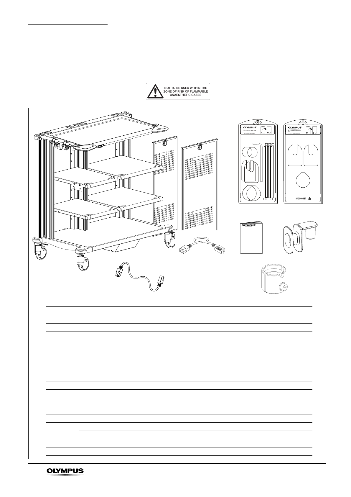
Standard Set and Accessories
Chapter 1 Standard Set and Accessories
Please refer to the standard set below and check that all items are present. Contact Olympus
if any parts are damaged or missing. Workstations that are fitted with antistatic castors can
be identified by the following label affixed to the rear of each shelf.
1
4
5
2
3
6
9
8
INSTRUCTIONS
10
7
Contents Qty
1 WM-DP1 mobile workstation (includes separation transformer) 1
2 Rear panel - narrow 1
3 Rear panel - wide 1
4 Blister pack 1
Blanking cap (cable port, 2pcs)
Blanking cap (monitor port, 2pcs)
Blanking cap (scope pole, 2pcs)
L-wrench ball driver 6mm A/F, 1 piece
Cable tie, 6 pcs
5 Blister pack 1
Blanking cap (cable port, 2pcs)
Blanking cap (monitor port, 1 piece)
6 Instruction manual 1
7 Cable hanger 2
8 Universal IEC cable 2.5m 4
Universal IEC cable 1.5m 4
9 IEC adaptor cable (USA only) 2
10 MAJ-181 restrictor assembly 2
3
MOBILE WORKSTATION WM-DP1
Page 5

1.1 Optional accessories
The following items are available as optional accessories. Each accessory is supplied
complete with the necessary fixings, tools and instructions to enable assembly to the mobile
workstation.
Description Ref No. GI SP EUS
14” CRT Platform WM-NP1 MAJ-1620
20” CRT Platform WM-NP1 MAJ-1621
Cable retaining hook MAJ-195
cylinder bracket kit large MAJ-188 – –
CO
2
cylinder bracket kit small MAJ-1614 – –
CO
2
Drawer pack narrow deep MAJ-194
Drawer pack narrow standard MAJ-193
Drawer pack wide deep MAJ-1612
Drawer pack wide standard MAJ-1611
Standard Set and Accessories
Recommended use
ECS cable kit 10m MAJ-186 –
ECS cable kit 15m MAJ-1616 –
Equipment support rail MAJ-190
EU-C60/2000 shelf kit MAJ-1627 – –
EUS Arm Mount Kit WM-P1 MAJ-1626 – –
IV pole kit MAJ-187 – –
Keyboard arm side mounted MAJ-180 –
Keyboard tray sliding MAJ-179
EU-M30 Keyboard Tray MAJ-1625 – –
LCD handle MAJ-1610
LCD monitor arm MAJ-181
Nurse’s control panel arm (long) MAJ-1628
Nurse’s control panel arm (short) MAJ-1624 – –
Scope pole kit MAJ-183
Shelf kit narrow MAJ-198
Shelf kit wide MAJ-199
Universal display arm CRT MAJ-1613 – –
Universal stowage container MAJ-185
Videoscope cable holder MAJ-1630
compatible – incompatible
CAUTION
Do not attempt to install any other accessories on the WM-DP1.
MOBILE WORKSTATION WM-DP1
4
Page 6

Warnings and Cautions
Chapter 2 Warnings and Cautions
WARNING
• The WM-DP1 mobile workstation should only be used in a medical
facility under the direction of a trained physician.
• Explosion hazard - never install or use the WM-DP1 mobile workstation
within the zone of risk of flammable gases. If the workstation is fitted
with antistatic castors (see Chapter 8), none of the medical electrical
equipment with which the workstation is intended to be used is ‘AP’ or
‘APG’ rated, therefore never install or use the WM-P1 series mobile
workstation within the zone of risk of flammable gases.
• To prevent patient shock, the combination of equipment used on the
WM-DP1 mobile workstation should never be applied directly to the
heart.
• If the fuse holder cap on the transformer is not fitted correctly, there is a
possibility that the fuse holder will overheat. When replacing the fuse,
ensure the fuse holder cap (Figure 4.3) is tightened using a 6mm to
8mm flat bladed screwdriver. The recommended tightening torque is
0.5Nm.
• Should the equipment become soiled with blood or other potentially
infectious materials, first wipe off all gross debris and then
decontaminate the equipment using a surface disinfectant, otherwise,
blood, mucus and other potentially infectious material from the patient
could pose an infection risk. Confirm that the equipment is completely
dry before use.
• Use personal protective equipment to guard against dangerous
chemicals and potentially infectious material, otherwise, blood, mucus
and other potentially infectious material from the patient could pose an
infection risk. During cleaning, wear appropriate protective equipment,
such as eye wear, face mask, moisture-resistant clothing and chemicalresistant gloves that fit properly and are long enough so that your skin is
not exposed.
• To prevent user or patient cross-contamination, do not hang
contaminated endoscopes on the scope hanger.
• The WM-DP1 should be used in accordance with the following.
Otherwise, the workstation will be ‘top heavy’ and may lose stability and
topple, causing equipment damage and/or personal injury.
- Two MAJ-181 restrictors are supplied which must be fitted to
MAJ-181 LCD monitor arm(s) if used (refer to section 4.8).
- LCD monitor arms and monitors should be installed after all
other equipment is installed on an appropriate place on the
workstation.
- LCD monitor arms should not be installed or used to the rear
of the workstation, see Figure 2.1.
- Confirm that the workstation does not lose stability when the
monitor arm is extended. If the workstation looks unstable,
relocate heavy equipment from the upper shelf to the bottom
shelf.
5
MOBILE WORKSTATION WM-DP1
Page 7

Warnings and Cautions
MAJ-181
(restrictor fitted)
MAJ-1624
or
MAJ-1628
Do not install or operate
LCD monitor arms in this zone
• Thoroughly review the manuals of all other equipment which will be
used. The manuals contain essential information on using this
equipment safely and effectively.
CAUTION
• Do not exceed the load capacity detailed in Chapter 8.
• Do not lean or stand on any part of the mobile workstation or accessory
as failure of the product may result.
• When assembling equipment onto the mobile workstation, the
installation should meet the requirements of EN IEC 60601-1-1:2001,
the safety standard for medical electrical systems.
• When configuring a system, the user should ensure that there is
sufficient spare equipment available that in the event of a fault in any
part of the system, the endoscopy procedure may be completed or
terminated without endangering the patient.
• Before commissioning an installation including a separation transformer,
ensure its rating will not be exceeded by the equipment connected to it.
• When installing the mobile workstation in the procedure or operating
room, ensure that the mains cable has sufficient slack that it cannot be
pulled taught as the mobile workstation is moved around the working
area. If necessary, relocate the mains connector to a nearer supply
socket.
Figure 2.1
• Section 6.2 Manoeuvring and Transportation gives detailed instructions
and precautions which must be read and understood before attempting
to move the mobile workstation.
MOBILE WORKSTATION WM-DP1
• Spray type medical agents, such as lubricants, anaesthetic or alcohol,
should be used away from the mobile workstation.
6
Page 8

Warnings and Cautions
• Keep open containers of liquid away from electrical equipment used on
the mobile workstation to prevent operator electrical shock and
equipment damage. Do not use the system if liquid has entered the
equipment.
• To minimise risk of injury, it is recommended that heavy items are placed
on the mobile workstation by two people working together. This is
particularly important when placing a monitor on the optional monitor
platform (if fitted). Ensure electrical items used on the mobile
workstation are positioned centrally on the shelves.
• Never place any items on top of a monitor (if fitted) as these may topple
when the mobile workstation is moved.
• Where fitted, the electrical resistance of the conductive antistatic castors
should be tested at regular intervals in accordance with ISO 2878 to
assess antistatic effectiveness.
• Where antistatic castors are fitted, avoid contact of the castor wheels
with oil and avoid a build up of floor cleaning wax and polish as these
will impair the antistatic effectiveness of the castors.
• Store and use the WM-DP1 mobile workstation within the environmental
conditions described in Chapter 8; failure to do so may lead to
equipment malfunction or failure.
• There are no operator-serviceable components on the WM-DP1 mobile
workstation. Refer servicing to qualified service personnel.
• To minimise the risk of injury and/or damage, do not fit accessories other
than those described in Section 1.1 to the WM-DP1 mobile workstation.
7
MOBILE WORKSTATION WM-DP1
Page 9

Chapter 3 Symbols
The following symbols are used on the separation transformer
Refer to instructions Potential equalisation terminal
Input Output
Symbols
Not exceeding
Standby position Fuse (output)
Output ON position Remote switch
Non-inherently short circuit
proof separation transformer
Unit complies with relevant
European directives
(MAJ-175 only)
View of the separation transformer rear panel
Ta=40°C
Class B
Maximum ambient
temperature
Insulation temperature rating
of transformer according to
IEC 60085:2004
Disposal conditions - see End
of Life (Chapter 12) (MAJ-175
only)
NOTE
MAJ-175 (220-240V) is shown. Other versions are similar.
MOBILE WORKSTATION WM-DP1
8
Page 10

Preparation for Use
Chapter 4 Preparation for Use
NOTE
• Multiple fixing positions are provided enabling the shelves to be raised
or lowered to accommodate varying equipment configurations (see 4.2).
• The mobile workstation is designed for use with Olympus OEV LCD
monitors and other monitors that meet the VESA standard. Contact
Olympus regarding compatibility of other monitors.
4.1 General information
Installation of endoscopic video systems requires an understanding of EN IEC 60601-1-1:2001,
the international collateral standard for the safety of medical electrical systems.
This standard requires systems to meet the leakage current requirements of the general medical
electrical safety standard, EN IEC 60601-1, which allows a maximum earth leakage current of
0.5mA in normal condition.
A separation transformer is required under certain circumstances, as combined earth leakage
currents may result in excessive enclosure leakage current under single fault conditions, such as
the interruption of a common protective earth path.
In order to meet EN IEC 60601-1-1:2001, a separation transformer will be required in a system
under one of the following conditions:
(i) Ancillary equipment that does not meet the leakage current requirements of
EN IEC 60601-1 is used (or could be used) within the ‘patient environment’ (as defined
in EN IEC 60601-1-1:2001, that is within a 1.5m radius of, or 2.5m above, the patient
bed). The separation transformer must be used to supply the ancillary equipment, but
may also be used to supply medical electrical equipment, as long as the maximum
transformer rating is not exceeded.
(ii) The total earth leakage current from a combination of medical equipment is above
0.5mA. The separation transformer must be used to supply sufficient of the medical
electrical equipment to reduce the total system earth leakage current to below the above
limit, as long as the maximum transformer rating is not exceeded. High intensity light
sources use arc lamps, which require a high start-up current. It is not recommended for
these to be supplied from the isolation transformer, otherwise its maximum rating may be
exceeded. The transformer may also be used to supply ancillary equipment forming part
of the system as long as the maximum transformer rating is not exceeded.
9
MOBILE WORKSTATION WM-DP1
Page 11

Preparation for Use
Some system installations, for instance those using two mobile workstations, may require two
separation transformers to be fitted.
NOTE
• The total impedance of the protective earth path for a system may be up
Ω
to 0.4
or higher if the conditions of clause 18 g) of EN IEC 60601-1 are
satisfied.
• The power outlets should only be used for powering equipment which
forms part of the endoscopy imaging system.
• All equipment forming part of the system should be powered from the
transformer, unless appropriate isolation is employed as described in
Annex BBB of EN IEC 60601-1-1:2001. This particularly applies where
ancillary equipment as described in (i) forming part of the system is
remotely situated.
CAUTION
• Failure to observe either of the above mentioned points could result in
the isolation of the entire system being compromised, defeating the
protection provided by the transformer in a single fault condition.
Additional fixings are provided (Figure 4.1) to facilitate shelf adjustment or the fitting of the optional
drawer pack(s).
MOBILE WORKSTATION WM-DP1
10
Page 12

Preparation for Use
318.00
11
Figure 4.1
MOBILE WORKSTATION WM-DP1
Page 13

Preparation for Use
4.2 Shelf positions
NOTE
The WM-DP1 mobile workstation is supplied with the shelves fitted as
shown in Figure 4.1. It is recommended that shelves are repositioned, if
required, before commencing equipment installation as described
below.
1. Position the mobile workstation on a flat surface and apply both castor brakes (diagonally
opposed).
2. Referring to Figure 4.2, use the 6mm A/F L-wrench to remove the four M8 screws with
crinkle and plain washers from the underside of the shelf.
Figure 4.2
3. Locate the shelf at the new position and fit the four side fixing screws with crinkle and plain
washers. Tighten all screws using a 6mm A/F L-wrench. It is recommended that after fitting,
the screws are tightened to a torque of 10.5Nm (tool not provided).
MOBILE WORKSTATION WM-DP1
12
Page 14

Preparation for Use
4.3 Remote switch
The remote switch enables the power to the system components to be controlled from a
single point. The switch is located beneath the top tray and connects to the remote switch
connector on the separation transformer via a 2m cable.
The remote switch has an integral two-colour LED which illuminates whenever the
transformer is connected to the mains supply. Yellow indicates ‘standby’, green indicates
‘output on’.
NOTE
• The remote switch only controls the output socket on the transformer. To
switch OFF the input power supply, set the remote switch to its
‘stand-by’ position, then disconnect the mains connector from the wall
outlet socket.
• In ‘stand-by’ condition, the transformer consumes a small amount of
power, typically 4% of its full load rating. If it is anticipated that the
system will not be used for a significant period of time, it is
recommended that the mains connector is removed from the wall outlet
socket to conserve energy.
1. The mobile workstation is supplied with the remote switch connected to the separation
transformer and no assembly is required. However, check the connection (see Figure 4.3) is
secure before completing full installation.
Potential
equalisation
terminals
Fuse
Remote switch
connector
13
Figure 4.3
MOBILE WORKSTATION WM-DP1
Page 15

4.4 Equipment installation
refer to section 4.1for additional information regarding system installations.
CAUTION
• To minimise risk of injury, it is recommended that two people, working
together, place heavy items of equipment on the mobile workstation.
• High intensity light sources may need to be connected to a properly
grounded AC power outlet and not one of the IEC power sockets on the
mobile workstation, depending on the total system power rating.
• Ensure the fully installed system meets the requirements of
EN IEC 60601-1-1:2001, Medical Electrical Equipment, Collateral
Standard: Safety Requirements for Medical Electrical Systems. For
advice, contact your Olympus representative or qualified service
personnel.
NOTE
Releasable cable straps are provided on the rear of each shelf and
cable ties are provided to secure equipment power cables to the case of
the transformer. Cable access holes are provided in the base of the
mobile workstation. Excess lengths of cables should be coiled neatly
and secured to the rear of a shelf using the cable straps provided.
Preparation for Use
1. Place items of equipment centrally on the shelving and connect according to individual
instructions. The WM-DP1 mobile workstation is supplied with a universal IEC lead set to
connect equipment on the mobile workstation to the transformer. Potential equalisation
terminals are fitted to both sides of the transformer enclosure for connection to equipment
potential equalisation terminals where fitted. Route all cabling neatly in the side column cable
ducts on the extrusion and along the rear of the shelves, secure using the releasable cable
ties (see Figure 4.4).
Centre column cable ducts are used for interconnection of equipment located on the base,
intermediate and upper shelves.
MOBILE WORKSTATION WM-DP1
14
Page 16

Preparation for Use
*****
*
*
*
*
*
*
* Denotes hidden cable ties
When all equipment is positioned on the workstation, install LCD monitor arms or control
2.
panels as required according to their instructions and noting the configuration diagrams
given in Chapter 2 Warnings and Cautions.
MAJ-181 only: One MAJ-181 restrictor (supplied) must be fitted to each MAJ-181 being
fitted, up to a maximum of two. The restrictor provides additional stability by preventing the
monitor arm from swinging outside the footprint of the workstation. Refer to Section 4.8 for
assembly.
WARNING
Do not use the MAJ-181 LCD monitor arm on the workstation without a
restrictor fitted. Otherwise the workstation may lose stability and topple,
causing equipment damage and/or personal injury.
Figure 4.4
3. Check that all equipment power ON/OFF switches are in the OFF position and connect the
separation transformer (and light source, where separate) power supply cables to properly
grounded AC power outlets. The power outlets should be located such that they are not
obstructed when the mobile workstation is in its normal operating position. The remote switch
LED will illuminate yellow indicating ‘standby’.
4. Set the mobile workstation remote switch to the ON position, the LED will now illuminate
green indicating ‘output on’.
5. Set the power switches for the installed equipment to the ON position.
15
MOBILE WORKSTATION WM-DP1
Page 17

CAUTION
• Check that all installed equipment operates correctly before using the
system ‘on patient’.
• The WM-T1 separation transformer incorporates a circuit to limit the
input current surge when power is applied. Operating an input power
ON/OFF switch several times in rapid succession may interfere with the
correct functioning of this circuit and may cause the mains power supply
protection to operate.
• Ensure that the video system centre is switched OFF when attaching or
removing the videoscope cable. Serious damage may result if the
videoscope is connected with the video system centre switched ON.
6. When equipment installation is complete, fit the rear door(s) taking care not to trap any
cables.
4.5 Cable hanger and blanking caps
NOTE
• If the cable hanger is not required, fit one blanking cap to the left hand
port in the top tray.
Preparation for Use
• Blanking caps are provided for each of the accessory fittings and cable
exits in the top tray. If accessories are fitted, the appropriate blanking
cap will not be required and should be stored in case of future use.
1. The blanking caps locate in the positions shown in Figure 4.5 and can be removed/fitted if
required.
Cable winder (or blanking cap, scope port if cable winder is not used)
Blanking cap, monitor port
Blanking cap, cable port
Handwheel
Figure 4.5
2. The cable hanger locates into either left or right hand port in the top tray and is secured in the
required position using handwheel as shown in Figure 4.5.
MOBILE WORKSTATION WM-DP1
16
Page 18

Preparation for Use
4.6 Water container holder
1. The WM-DP1 mobile workstation is fitted with a water container bracket to hold two water
containers (not supplied). The water container simply clips onto the bracket as shown in
Figure 4.6.
4.7 Rear panels
1. When installation of equipment is complete, lift each rear panel in turn onto the locating studs
on the base of the workstation (Figure 4.7) then push the top of the panel until the latch
engages with an audible click.
Figure 4.6
17
Rear panel - narrow
Rear panel - wide
Figure 4.7
MOBILE WORKSTATION WM-DP1
Page 19

Preparation for Use
4.8 Fitting the MAJ-181 restrictor
This procedure is only applicable if fitting a MAJ-181 LCD monitor arm to the WM-DP1 workstation.
WARNING
• If using a MAJ-181 on the workstation, the restrictor supplied in this kit
must be fitted to the MAJ-181 and is best assembled with the MAJ-181
in position on the workstation.
• To maintain stability, before installing a second MAJ-181, ensure the first
is assembled with the restrictor fitted.
• Read the instruction manual supplied with the MAJ-181, it contains
important information regarding proper care and use of the equipment.
• The WM-DP1 should be used in accordance with the following.
Otherwise, the workstation will be ‘top heavy’ and may lose stability and
topple, causing equipment damage and/or personal injury.
- Two MAJ-181 restrictors are supplied which must be fitted to
MAJ-181 LCD monitor arm(s) if used.
- LCD monitor arms and monitors should be installed after all
other equipment is installed on an appropriate place on the
workstation.
- LCD monitor arms should not be installed or used to the rear
of the workstation, see Figure 2.1.
- Confirm that the workstation does not lose stability when the
monitor arm is extended. If the workstation looks unstable,
relocate heavy equipment from the upper shelf to the bottom
shelf.
1. Referring to the MAJ-181 instruction manual, relocate the clamp support to another fixing
hole in the support tube (see Figure 4.8) as the restrictor will be fitted through the top hole,
then insert the MAJ-181 into the monitor port in the top tray of the workstation.
MOBILE WORKSTATION WM-DP1
18
Page 20

Preparation for Use
Referring to Figure 4.9, pull out the finger grip on the lower index plunger and rotate it 90°,
2.
the arm is now free to rotate. Rotate the arm until parallel with the top tray as shown.
Top view
Rotate arm
MAJ-181
Index plunger
to disengage
3. Remove the M8 screw to separate the MAJ-181 restrictor assembly.
Figure 4.8
Figure 4.9
4. Referring to Figure 4.10, secure the MAJ-181 restrictor - front to the MAJ-181 restrictor - rear
through the uppermost hole in the monitor arm using the M8 coil washer, M8 plain washer
and M8 x 50mm screw. Fully tighten the screw using the M6 A/F Allen key supplied.
NOTE
The monitor arm must be parallel to the top tray to ensure the tag on the
monitor arm aligns with the cutout in the restrictor (Figure 4.10 inset).
19
MOBILE WORKSTATION WM-DP1
Page 21

MAJ-181 restrictor - rear
Preparation for Use
MAJ-181 restrictor - front
Repeat for second MAJ-181 if used.
5.
M8 x 50mm screw
M8 coil washer
M8 plain washer
Figure 4.10
MOBILE WORKSTATION WM-DP1
20
Page 22

Inspection
Chapter 5 Inspection
WARNING
Should the slightest irregularity be suspected, do not use the mobile
workstation and refer to Chapter 11 Troubleshooting. If the problem
cannot be resolved, contact Olympus for service.
1. Check the power supply cable and plug for damage, twists, deformation or other
irregularities.
2. Where antistatic castors are fitted, periodically check the electrical resistance of the
conductive antistatic castors to assess antistatic effectiveness.
3. Check the security of castors at six-monthly intervals. If loose, contact Olympus for service.
4. Regularly check the shelf fixing screws and the fixing screws of any accessories that are
fitted, particularly monitor mounts. If necessary, retighten the screws using the tools
provided.
21
MOBILE WORKSTATION WM-DP1
Page 23

Chapter 6 Operation
6.1 Operation
WARNING
• The WM-DP1 should be used in accordance with the following.
Otherwise, the workstation will be ‘top heavy’ and may lose stability and
topple, causing equipment damage and/or personal injury.
Operation
- Two MAJ-181 restrictors are supplied which must be fitted to
MAJ-181 LCD monitor arm(s) if used (refer to section 4.8).
- LCD monitor arms and monitors should be installed after all
other equipment is installed on an appropriate place on the
workstation.
- LCD monitor arms should not be installed or used to the rear
of the workstation, see Figure 2.1.
- Confirm that the workstation does not lose stability when the
monitor arm is extended. If the workstation looks unstable,
relocate heavy equipment from the upper shelf to the bottom
shelf.
CAUTION
• Place the mobile workstation on a flat level surface and lock the castor
brakes.
• Confirm that any mounted instruments function normally before using
the system on a patient.
1. Plug the power cord of the mobile workstation into a hospital-grade power outlet.
2. Confirm that the power indicator on the remote switch lights yellow.
3. When the remote switch is ON, confirm that the power indicator lights green.
4. For use of Optional accessories, please refer to each accessory instruction manual.
5. During use, do not position LCD monitor arms to the rear as shown below. Otherwise, the
workstation may lose stability and topple, causing equipment damage and/or personal injury.
MOBILE WORKSTATION WM-DP1
22
Page 24

Operation
After use, turn off the remote switch.
6.
Figure 6.1
23
MOBILE WORKSTATION WM-DP1
Page 25

6.2 Manoeuvring and Transportation
WARNING
• The WM-DP1 should be manoeuvred or transported in accordance with
the following. Otherwise, the workstation may lose stability and topple,
causing equipment damage and/or personal injury.
- Two people are required to safely manoeuvre or transport a
loaded mobile workstation.
- Do not manoeuvre or transport the workstation quickly or
aggressively, especially when negotiating bumps.
- Check that all cables are secure and clear of the castors.
- All optional accessories fitted to the workstation should be
placed in the stowage position in accordance with their
instructions for use.
1. The mobile workstation has two diagonally located braked castors. Ensure both brakes are
applied prior to use.
2. Ensure both brakes are released before attempting to move the mobile workstation.
Operation
3. Always manoeuvre the mobile workstation using the handles provided on the front of the top
tray. Care must be exercised when moving it, particularly over uneven surfaces or trailing
cables, to avoid tipping.
4. Before attempting to move the mobile workstation outside the operating room, ensure that its
mains cable is disconnected from the supply socket and is safely coiled away from the
castors, and that the equipment housed on the mobile workstation is secure. Ensure that the
endoscope is removed and transported separately and fluid containers are removed and
emptied. Optional accessories such as LCD monitors or control panels, if fitted, should be
rotated within the footprint of the mobile workstation and locked in position. Take particular
care of any accessories (if fitted) which protrude from the frame.
5. Two people are required to safely transport a loaded mobile workstation outside the
procedure room. Particular care must be taken when moving up or down slopes to prevent
loss of control of the mobile workstation.
6. When the mobile workstation is fully loaded with equipment, do not attempt to `park' it on
slopes or inclines as the castor brakes may not be fully effective.
7. It is recommended that the mobile workstation is manoeuvred over lips or door thresholds
diagonally (see Figure 6.2) , that is one castor at a time, to minimise the potential for tipping.
MOBILE WORKSTATION WM-DP1
24
Page 26

Operation
Higher level
Lower level
Higher level
Lower level
NOTE
1
2
Figure 6.2
Repeated transportation over uneven surfaces may result in damage to
the equipment carried on the mobile workstation.
25
MOBILE WORKSTATION WM-DP1
Page 27

Care, Storage and Maintenance
Chapter 7 Care, Storage and Maintenance
7.1 Care
1. Clean the mobile workstation with a soft cloth or gauze moistened with a neutral detergent,
then wipe over with a cloth dampened with 70% alcohol.
2. The umbilical holders should be removed and cleaned/sterilised before use by autoclaving
(to a maximum of 138°C (280°F)) or disinfected by cold fluid immersion following solution
manufacturer’s instructions.
To remove the umbilical holder, squeeze and rotate to the left or right to disengage from the
tabs on the bracket. To replace, locate the left or right side onto the tab and rotate into the
holder until the second tab engages.
WARNING
Figure 7.1
• Should the equipment become soiled with blood or other potentially
infectious materials, first wipe off all gross debris and then
decontaminate the equipment using a surface disinfectant, otherwise,
blood, mucus and other potentially infectious material from the patient
could pose an infection risk. Confirm that the equipment is completely
dry before use.
• Use personal protective equipment to guard against dangerous
chemicals and potentially infectious material, otherwise, blood, mucus
and other potentially infectious material from the patient could pose an
infection risk. During cleaning, wear appropriate protective equipment,
such as eye wear, face mask, moisture-resistant clothing and chemicalresistant gloves that fit properly and are long enough so that your skin is
not exposed.
MOBILE WORKSTATION WM-DP1
26
Page 28

Care, Storage and Maintenance
CAUTION
• Do not allow any fluids into contact with electrical equipment installed on
the mobile workstation.
• Do not use harsh or abrasive cleaning materials on the mobile
workstation.
• Ensure all surfaces are thoroughly dried before reusing the mobile
workstation.
7.2 Storage
1. The WM-DP1 mobile workstation should be stored within the environmental conditions given
in Chapter 8.
7.3 Maintenance
1. Check the security of castors at six-monthly intervals. If loose, contact Olympus for service.
2. Where antistatic castors are fitted, periodically check the electrical resistance of the
conductive antistatic castors to assess antistatic effectiveness.
Periodically clean each castor wheel to remove non-conductive material such as cleaning
wax and floor polish as these will impair the antistatic effectiveness of the castors.
3. Regularly check the shelf and securing screws of any accessories that are fitted, particularly
monitor platforms. If necessary, retighten the screws using the tools provided.
4. The separation transformer should undergo routine checks for electrical safety and correct
function annually or as dictated by local policy. Typical checks would include inspection of the
power supply cable for damage, and tests for earth continuity and insulation resistance. Also
check (listen) for correct operation of the inrush limiting circuit (see Chapter 10) when power
is applied.
5. Annually, check that the fuse holder cap on the transformer (Figure 4.3) is correctly fitted. If
the fuse has been replaced and the cap is not sufficiently tightened, there is a possibility that
the fuse holder will overheat. When replacing the fuse, ensure the fuse holder cap is
tightened using a 6mm to 8mm flat bladed screwdriver. The recommended tightening torque
is 0.5Nm.
6. If it becomes necessary to remove the separation transformer from the mobile workstation
for testing, disconnect all cables from the transformer then place supports between the
transformer and the floor at the front and rear. Remove four M8 nuts using a 13mm A/F
socket, then carefully remove the supports and lower the transformer to the floor.
WARNING
Do not extend any monitor arm outside the footprint of the workstation
when the transformer is removed. Otherwise the workstation will be ‘top
heavy’ and may lose stability and topple, causing equipment damage
and/or personal injury.
CAUTION
• The transformer weighs up to 28kg, and care should therefore be
exercised during handling. When lifting the transformer, it is
recommended that the assistance of a second person is sought.
27
• Removal of the transformer should only be undertaken by suitably
qualified personnel.
• Electrical safety checks should only be performed by suitably qualified
personnel.
MOBILE WORKSTATION WM-DP1
Page 29

Chapter 8 Specifications
8.1 WM-DP1 mobile workstation
Product name WM-DP1 mobile workstation
Dimensions (mm) Height: 1192
1370 (scope in lowest position)
2140 (scope in highest position)
1826 max (with 19” LCD monitor in highest position)
Depth: 655
Width: 1238
Weight 120kg unladen, including fitted transformer.
Load capacity
(evenly distributed)
Top tray 10kg
Intermediate shelves 26kg each
Base panel 60kg
Total load 180kg maximum (inclusive of attached
accessories and equipment)
Specifications
NOTE: Equipment stored on the mobile workstation should not exceed
the size of the shelf.
Castors WM-DP1 p/no K10003727
4 x 125mm antistatic, two with brakes.
WM-DP1 p/no K10003726, K10003728, K10003729
4 x 125mm non-antistatic, two with brakes.
Ambient temperature Storage: -40°C to +70°C (-40°F to +158°F)
Operation: 10 - 40°C (50 - 104°F)
Relative humidity 95% maximum @ 40°C (104°F) non-condensing
Atmospheric pressure
Storage: 23.5-106 kPa (3.4-15.37lbf/in
Operation: 70-106 kPa (10.15-15.37lbf/in
2
)
2
)
8.2 Separation transformer (WM-T1)
Product name Olympus Separation Transformer
Identification Market USA UK, Europe,
Rest of the world
Model No. MAJ-174 MAJ-175
Part No. K10000290 K10000291
Power input
requirements
Power output Maximum load 1250VA 1800VA
Input voltage 110-120V 220-240V
Frequency 60Hz 50/60Hz
Power input (max) 1300VA 1900VA
Power cable part No. K10001002 K10001003 (UK)
K10001004 (Europe)
K10001005 (RoW)
MOBILE WORKSTATION WM-DP1
28
Page 30

Specifications
Overload
protection
Input circuit breakers 2 x 13A 2 x 9A
Output fuse T15AH T10AH
Tighten to 0.5Nm reference
IEC 60127-6:1994
Potential
Terminals fitted 2 at input, 2 x 6 at output
equalisation
Classification Standards compliance The Separation Transformer conforms to the relevant
requirements of: EN IEC 60601-1/
EN IEC 60601-1-1:2001, Annex EEE/UL 60601-1 and
CAN/CSA Std. No. C22.2 No. 601.1-M90
Type of protection against
Class I equipment.
electric shock.
Degree of protection against
explosion
Degree of protection against
ingress of water.
None, the Separation transformer should not be used
within the zone of risk of flammable gases
IPX0 as defined in EN IEC 60529:1992, ordinary
equipment.
Mode of operation Continuous
Environmental
conditions
Ambient temperature Storage: -40°C to +70°C (-40°F to +158°F)
Operation: 10 − 40°C (50 - 104°F)
Atmospheric pressure
Storage: 23.5-106 kPa (3.4-15.37lbf/in
Operation: 70-106 kPa (10.15-15.37lbf/in
2
)
2
)
Relative humidity 95% maximum @ 40°C (104°F) non-condensing
Regulatory
status
European Economic Area
(EEA)
220-240V units are CE marked in
accordance with Directive 93/42/EEC of
14 June 1993 concerning medical
devices, as an accessory to a medical
device, Class I. Year of manufacture is
given in first two digits of serial number.
End of Life
In accordance with European Directive
2002/96/EC on Waste Electrical and
Electronic Equipment, this symbol
indicates that the product must not be
disposed of as unsorted municipal waste,
but should be collected separately. Refer
to your local Olympus distributor for return
and/or collection systems available in
your country.
The Olympus WM-DP1 mobile workstation and separation transformer is manufactured in the UK
by KeyMed (Medical & Industrial Equipment) Ltd.
29
MOBILE WORKSTATION WM-DP1
Page 31

Chapter 9 Spares
NOTE
In order to maintain standards compliance, it is important that
replacement components should have the same specification as those
fitted originally. This can best be guaranteed by using only those spare
parts and components specified and supplied by Olympus.
1. If any item becomes damaged or lost, contact Olympus for replacement.
Spares
MOBILE WORKSTATION WM-DP1
30
Page 32

Technical Description
Chapter 10 Technical Description
The block diagram shown in Figure 10.1 shows the different sub-units within the Separation
Transformer.
The mains cable connects to the transformer through a high current IEC-320 style connector,
allowing it to be easily replaced if it becomes damaged during use. It is secured to the transformer
by a pair of clamps, to prevent accidental disconnection during use. The protective earth terminal
connects to the metal enclosure of the unit and the output socket earthing system; the line and
neutral conductors connect to the primary side of the transformer via two thermal circuit breakers
and an inrush limiting circuit.
As with any transformer, the primary circuit will draw an inrush current surge when it is connected
to the mains supply, which can sometimes be very large, depending on the magnetic state of its
core at the instant it is powered. The inrush limiting circuit inserts a high power thermistor in series
with the primary winding to limit the initial surge, dissipating it as heat. After approximately 0.5
seconds a relay closes (producing an audible ‘click’) to by-pass the thermistor, both to avoid any
steady-state losses that would adversely affect the load regulation and to allow it to cool in
readiness for the next switch-on.
The transformer is wound with a nominal input-to-output ratio of 1:1, with concentric primary and
secondary windings. An additional low voltage secondary winding powers the circuit for the remote
switch. Electrical separation between windings is maintained by overlapping layers of “Nomex” and
“Melinex” tapes.
The secondary winding supplies power to the separated output sockets via a fuse to protect the
unit against short-circuit faults in the external equipment. An additional socket enables a remote
switch to be connected if required, operating a relay to control the power to the output sockets.
This provides a convenient way of turning the entire system (apart from the transformer itself) on or
off from a central point on the mobile workstation. When the remote switch is not connected, the
outputs default to the permanently energised state. To isolate the unit from the mains supply, set
the remote switch to its stand-by’ position, then disconnect the mains connector from the wall
outlet socket.
Potential equalisation terminals are provided adjacent to the input cable and either side of the top
cover, for use where local regulations require the enclosures of each part of the system be
connected to a common earth point, independently of the mains supply cables.
31
MOBILE WORKSTATION WM-DP1
Page 33

SOCKETS
OUTPUT
FUSE
OUTPUT
(COVER)
TERMINALS
EQUIPOTENTIAL
Technical Description
CIRCUIT
BREAKER
L
INRUSH
CIRCUIT
LIMITING
MAINS
CABLE
RELAY
SWITCH
CIRCUIT
BREAKER
N
CIRCUIT
INLET
CONNECTOR
REMOTE
ENCLOSURE
SWITCH
MOBILE WORKSTATION WM-DP1
Figure 10.1
32
Page 34

Troubleshooting
Chapter 11 Troubleshooting
Problem Possible cause Remedy
No power to separation
transformer
Output fuse blows Item of equipment connected
Circuit breaker(s) ‘trip’ Combined rating of equipment
Interference to equipment
connected to the transformer.
Separation transformer not
connected to AC wall outlet
No power at AC wall outlet Check power supply to AC wall
to transformer is faulty
connected to power sockets
exceeds the maximum VA
rating of the transformer.
Magnetic - proximity of
sensitive equipment to
transformer magnetic field.
Electrical - typically distortion /
interference on monitor display
when equipment is operated.
Connect transformer cable to
AC wall outlet
outlet
Disconnect transformer from
power supply. Locate and
repair faulty equipment.
Replace output fuse and
reconnect all equipment.
Check combined rating is
within the maximum limit,
disconnect equipment if
necessary. Reset circuit
breaker(s) by pressing in
circuit breaker button.
Relocate sensitive equipment
to a higher shelf.
Check system for damaged
cables or connections.
Electromagnetic - interference
from other systems.
If the problem cannot be resolved, contact Olympus for service. There are no user-serviceable
parts inside the separation transformer. This equipment must not be modified without written
authorisation from Olympus.
As above, plus investigate
source of interference.
33
MOBILE WORKSTATION WM-DP1
Page 35

Chapter 12 End of Life
Equipment which has reached the end of its useful life should be disposed of according to local
regulations, refer to section 8.2 for additional information.
End of Life
MOBILE WORKSTATION WM-DP1
34
Page 36

OLYMPUS MEDICAL SYSTEMS CORP.
2951 Ishikawa-cho, Hachioji-shi, Tokyo 192-8507, Japan
Fax: (042) 646-2429 Telephone: (042) 642-2111
OLYMPUS MEDICAL SYSTEMS EUROPA GMBH
(Premises/Goods delivery) Wendenstrasse 14-18, D-20097 Hamburg, Germany
(Letters) Postfach 10 49 08, D-20034 Hamburg, Germany Telephone: (040) 237730
EC REP
OLYMPUS AMERICA INC.
3500 Corporate Parkway, P.O. Box 610 Center Valley, PA 18034-0610, U.S.A.
Fax: (484) 896-7128 Telephone: (484) 896-5000
KEYMED LTD.
KeyMed House, Stock Road, Southend-on-Sea, Essex SS2 5QH, United Kingdom
Fax: (01702) 465677 Telephone: (01702) 616333
EC REP
OLYMPUS SINGAPORE PTE LTD.
491B, River Valley Road #12-01/04, Valley Point Office Tower, Singapore 248373
Fax: 6834-2438 Telephone: 6834-0010
OLYMPUS (BEIJING) SALES & SERVICE CO,. LTD.
Room 1202, NCI Tower, A12 Jianguomenwai Avenue, Chaoyang District, Beijing, 100022 P.R.C.
Fax: (10) 6569-3545 Telephone: (10) 6569-3535
OLYMPUS MOSCOW LIMITED LIABILITY COMPANY
117071, Moscow, Malaya Kaluzhskaya 19, bld. 1, fl.2, Russia
Fax: (095) 958-2277 Telephone: (095) 958-2245
OLYMPUS AUSTRALIA PTY. LTD.
31 Gilby Road, Mount Waverley, Victoria 3149, Australia
Fax: (03) 9543-1350 Telephone: (03) 9265-5400
Issue 4
May 2009
OLYMPUS LATIN AMERICA INC.
5301 Blue Lagoon Drive, Suite 290, Miami, FL 33126, U.S.A.
Fax: (305) 261-4421 Telephone: (305) 266-2332
OLYMPUS KOREA CO,. LTD.
4F, 5F, Gyeongam Bldg., 157-27 Samseong-Dong, Kangnam-Gu, Seoul 135-090 Korea
Fax: (02) 6255-3499 Telephone: (02) 1544-3200
©KeyMed 2009
Printed in UK
K10005955/509
 Loading...