

Page 1

MAINTENANCE & REPAIR MANUAL
WM--P1 SERIES MOBILE WORKSTATIONS
WM--NP1
WM--WP1
WM--DP1
OLYMPUS MEDICAL SYSTEMS CORP.
2951 Ishikawa-cho, Hachioji-shi, Tokyo 192-8507, Japan
Fax: (042) 646-2429 Telephone: (042) 642-2111
OLYMPUS EUROPA HOLDING GMBH
(Premises/Goods delivery) Wendenstrasse 14-18, 20097 Hamburg, Germany
(Letters) Postfach 10 49 08, 20034 Hamburg, Germany
Fax: (040)23773-4656 Telephone: (040)23773-0
OLYMPUS AMERICA INC.
3500 Corporate Parkway, P.O. Box 610, Center Valley, PA
Fax: (484) 896-7128 Telephone: (484) 896-5000
18034-0610, U.S.A.
KEYMED LTD.
KeyMed House, Stock Road, Southend-on-Sea, Essex SS2 5QH, United Kingdom
Fax: (01702) 465677 Telephone: (01702) 616333
OLYMPUS SINGAPORE PTE LTD.
491B, River Valley Road #12-01/04, Valley Point Office Tower, Singapore 248373
Fax: 6834-2438 Telephone: 6834-0010
OLYMPUS (BEIJING) SALES & SERVICE CO,. LTD.
A8F, Ping An International Financial Center, No. 1-3, Xinyuan South Road,
Chaoyang District, Beijing, 100027 P.R.C.
Fax: (86)10-5976-1299 Telephone: (86)10-5819-9000
OLYMPUS MOSCOW LIMITED LIABILITY COMPANY
117071, Moscow, Malaya Kaluzhskaya 19, bld. 1, fl.2, Russia
Fax: (095) 958-2277 Telephone: (095) 958-2245
OLYMPUS AUSTRALIA PTY. LTD.
31 Gilby Road, Mount Waverley, VIC., 3149, Australia
Fax: (03)9543-1350 Telephone: (03)9265-5400
OLYMPUS LATIN AMERICA INC.
5301 Blue Lagoon Drive, Suite 290 Miami, FL 33126-2097, U.S.A.
Fax: (305)261-4421 Telephone: (305)266-2332
OLYMPUS KOREA CO,. LTD.
Olympus-Tower, 114-9 Samseong-Dong, Gangnam-Gu, Seoul 135-090 Korea
Fax: (02)6255-3494 Telephone: (02)6255-3210
Issue 20
July 2012
EKeyMed 2012
K 5070557
Page 2

MAINTENANCE & REPAIR MANUAL
M- NP1 / WM- WP1 / WM- DP1 WORKSTATIONS
CHANGE OF ISSUE LOG
When an up--issued copy of this manual is received, record its receipt on this page.
A brief description of the change can be found on the last page of the manual : Summary of Change History.
Changes made to the current issue are highlighted in the manual by a vertical line in the right hand margin.
Each up--issued copy of the manual will include an up--issued copy of this page but it does not have to be retained unless needed as a
continuation sheet.
Date Issue
number of
manual
Signature Date Issue
number of
manual
Signature
WM--P1 SERIES WORKSTATIONS
Page2of 76
Issue 20 : July 2012
Page 3

MAINTENANCE & REPAIR MANUAL
WM- NP1 / WM- WP1 WM - DP1
Manual Contents
Page
Preliminary Material
Title Page 1..................................................................
Change of issue log 2...........................................................
Manual Contents (this page) 3.....................................................
Chapters
1 Introduction 4.........................................................
2 General Information 6...................................................
3 Specifications 8.......................................................
4 Tools & Test Equipment 12...............................................
5 Test and Inspection 14..................................................
6 Part Replacement 16...................................................
7 Illustrated Parts List 27..................................................
8 Accessories Illustrated Parts List 39.........................................
Summary of Change History 76............................................
WM--P1 SERIES WORKSTATIONS
Page3of 76
Issue 20 : July 2012
Page 4

Chapter 1 Introduction
Table of Contents
Page
Introduction 5.........................................................
WM--P1 SERIES WORKSTATIONS
Page4of 76
Issue 20 : July 2012
Page 5

1 INTRODUCTION
This Maintenance and Repair Manual has been produced by KeyMed to enable the repair and servicing of the Olympus WM--P1
series mobile workstation.
Although every effort has been made to ensure that this document is correct and complete, KeyMed cannot be held responsible
for the safety or reliability of any equipment which has been repaired other than by suitably qualified personnel. It is essential
that this manual is read and understood before commencing any work.
Should any additional information or advice be required, please contact:
Olympus KeyMed
Technical Services
Technical Support
KeyMed House
Stock Road
SOUTHEND--ON--SEA
Essex SS2 5QH
United Kingdom
Tel: (01702) 616333
Fax: (01702) 465677
Telex: 995283
WM--P1 SERIES WORKSTATIONS
Page5of 76
Issue 20 : July 2012
Page 6

Chapter 2 General Information
Table of Contents
Page
General information 7...................................................
WM--P1 SERIES WORKSTATIONS
Page6of 76
Issue 20 : July 2012
Page 7

2 GENERAL INFORMATION
The Olympus WM--P1 series mobile workstation is intended for use in medical facilities under the direction of a trained
physician, and has been designed to accommodate the Olympus video system center and associated ancillary devices as a
practical mobile workstation to facilitate GI endoscopy, endoscopic ultrasound, respiratory and surgical endoscopic procedures.
Olympus will not be responsible for damage or injury to equipment or personnel, caused by unauthorised modification or repair
to this unit.
Maintenance
In the interest of safety and good maintenance, ensure that all fixings are secure. It is recommended that the security fixing
torques of the monitor platform, shelf’s, castors and side column fixings specified in the illustrated parts list, are checked every
six months.
WM--P1 SERIES WORKSTATIONS
Page7of 76
Issue 20 : July 2012
Page 8

Chapter 3 Specifications
Table of Contents
Page
3.1 WM--NP1 / WM--WP1 series mobile workstations 9..............................
3.2 WM--DP1 series mobile workstations 10......................................
3.3 WM--T1 series separation transformers 10....................................
WM--P1 SERIES WORKSTATIONS
Page8of 76
Issue 20 : July 2012
Page 9

3 SPECIFICATIONS
3.1 WM- NP1 / WM- WP1 series mobile workstations
Product name WM--NP1 / WM--WP1 mobile workstation
Dimensions (mm) Height: 1370 (scope in lowest position)
2140 (scope in highest position)
1160 (to top tray)
1826 max (with 19” LCD monitor in highest position)
Depth: 650
Width: 645 (WM--NP1) 795 (WM--WP1)
Weight 85kg (WM-- NP1) 90kg (WM-- WP1) unladen, including fitted transformer.
Load capacity
(evenly distributed)
Castors 4 x 125mm non--antistatic, two with brakes.*
Ambient temperature Storage: --40Cto+70C
(--40F to +158F)
Relative humidity 95% maximum @ 40C (104F) non--condensing
Atmospheric pressure
* UK workstations fitted with Antistatic castors from Oct 2007.
Top tray 20kg
Intermediate shelves 31kg each
Base panel 31kg
NOTE: Equipment stored on the mobile workstation should not exceed
the size of the shelf.
Operation: 10 -- 40C (50 -- 104F)
Storage: 23.5-- 106 kPa (3.4 --15.37lbf/in
Operation: 70-- 106 kPa (10.15 --15.37lbf/in
2
)
2
)
WM--P1 SERIES WORKSTATIONS
Page9of 76
Issue 20 : July 2012
Page 10

3.2 WM- DP1 series mobile workstations
Product name WM--DP1 mobile workstation
Dimensions (mm) Height: 1370 (scope in lowest position)
2140 (scope in highest position)
1160 (to top tray)
1826 max (with 19” LCD monitor in highest position)
Depth: 655
Width: 1100
Weight 120kg unladen, including fitted transformer.
Load capacity
(evenly distributed)
Top tray 10kg
Intermediate shelves 26kg each
Base panel 45kg
NOTE: Equipment stored on the mobile workstation should not exceed
the size of the shelf.
Castors 4 x 125mm non--antistatic, two with brakes.*
Ambient temperature Storage: --40Cto+70C
(--40F to +158F)
Operation: 10 -- 40C (50 -- 104F)
Relative humidity 95% maximum @ 40C (104F) non--condensing
Atmospheric pressure
Storage: 23.5-- 106 kPa (3.4 --15.37lbf/in
Operation: 70-- 106 kPa (10.15 --15.37lbf/in
* UK workstations fitted with Antistatic castors from Oct 2007.
2
)
2
)
3.3 WM- T1 series separation transformers
Product name Olympus Separation Transformer
Identification Market Japan USA UK, Europe,
Rest of the world
Model No. MAJ--173 MAJ--174 MAJ--175
Part No. K10000289 K10000290 K10000291
Power input
requirements
Input voltage 100V 110-- 120V 220 --240V
Frequency 50/60Hz 60Hz 50/60Hz
Power input (max) 1350VA 1300VA 1900VA
Power cable part No. K10001001 K10001002 K10001003 (UK)
K10001004 (Europe)
K10001005 (RoW)
Power output Maximum load 1250VA * 1250VA 1800VA
* Maximum 10A load per IEC socket outlet (MAJ--173 only)
Overload
protection
WM--P1 SERIES WORKSTATIONS
Input circuit breakers 2 x 15A 2 x 13A 2 x 9A
Output fuse T15AH T15AH T10AH
Issue 20 : July 2012
Page 10 of 76
Page 11
Potential
Classificatio
Classificatio
n
Amb
ient
t
EnvironmentalconditionsAt
S
t
/
O
t
i
7
0--106kPa(10.3--1
5.4lbf/
in2
)
equalisation
Terminals fitted 2 at input, 2 x 6 at output
The Separation Transformer conforms to the relevant
Standards compliance
requirements of
EN IEC 60601--1/EN IEC 60601--1--1:2001, Annex EEE/UL
60601--1 and CAN/CSA Std. No. C22.2 No. 601.1--M90
n
Environmental
Regulatory status
End of Life
Type of protection against electric
Class I equipment.
shock.
Degree of protection against
explosion
Degree of protection against ingress
of water.
NONE -- The Separation transformer should not be used
within the zone of risk of flammable gases
IPXO as defined in EN IEC 60529:1992, ordinary equipment.
Mode of operation Continuous
Storage: --40Cto70C(--40F to 158F)
emperature
mospheric pressure
Operation: 10Cto40C(50F to 104F)
orage
pera
on:
Relative humidity 95% maximum @ 40C (104F) non--condensing
220--240V units are CE marked in
accordance with Directive 93/42/EEC of
14 June 1993 concerning medical
devices, as an accessory to a medical
device, Class I. Year of manufacture is
given in first two digits of serial number.
In accordance with European Directive
European Economic Area (EEA)
2002/96/EC on Waste Electrical and
Electronic Equipment, this symbol
indicates that the product must not be
disposed of as unsorted municipal waste,
but should be collected separately. Refer
to your local Olympus distributor for r eturn
and/or collection systems available in your
country.
The Olympus WM--P1 series Mobile Workstation and Separation Transformer is manufactured in the
UK by KeyMed (Medical & Industrial Equipment) Ltd.
Page 11 of 76
WM--P1 SERIES WORKSTATIONS
Issue 20 : July 2012
Page 12

Chapter 4 Tools & Test Equipment
Table of Contents
4.1 Standard Tools and Test equipment required 13................................
4.2 Specialised tools required 13..............................................
4.3 Consumables 13......................................................
WM--P1 SERIES WORKSTATIONS
Page 12 of 76
Issue 20 : July 2012
Page 13

4 TOOLS & TEST EQUIPMENT
4.1 Standard Tools required
Flat blade screwdriver Torque driver
No 2 Pozidrive tool bit No 3 Pozidrive tool bit
4mm Hex tool bit 8mm Hex tool bit
10mm Hex tool bit 10mm A/F socket
13mm A/F Slim socket Ball driver 6mm A/F
Short No 2 Pozidrive screwdriver Torx bit T30
Torque wrench (1/2” drive).. M12 tap
Britool part no AVT300A Torque range 5 to 33 Nm.
Insulation tester which works at 500Vdc. --
4.2 Specialised Tools
Castor spanner WM--P1 -- K10005023 --used with 1/2” drive torque wrench.
4.3 Consumables
Loctite 243 10ml bottle -- part number K10006486
FIGURE 4-1
CASTOR SPANNER WM--P1 --
K10005023
Loctite 243 -- part number 3001857
WM--P1 SERIES WORKSTATIONS
Page 13 of 76
Issue 20 : July 2012
Page 14

Chapter 5 Test and Inspection
Table of Contents
5.1 Power supply 15.......................................................
5.2 Castor security 15.....................................................
5.3 Castor -- electrical resistance test 15........................................
Page
WM--P1 SERIES WORKSTATIONS
Page 14 of 76
Issue 20 : July 2012
Page 15

5 TEST AND INSPECTION
5.1 Power supply
(1) Check the power supply cable and plug for excessive protrusion, twists, deformation or other irregularities.
5.2 Castor security
(1) Check the security of castors at six--monthly intervals. If loose use castor spanner ( K10005023) fitted to a standard 1/2”
drive torque driver to tighten to a torque of 30Nm.
If castor spanner ( K10005023) is not used, then torque value on the driver should be set to 38Nm. Refer to Chap 6.6.
5.3 Castors - electrical resistance test
NOTE
This test is only applicable to workstations fitted with ’anti--static’ castors, indicated by a yellow wheel centre or
swivel bearing collar, or a yellow dot on the tyre.
(1) Ensure that the workstation power cable is disconnected from the wall socket.
(2) Thoroughly clean each of the tyres.
(3) Roll a castor onto a metal plate which is insulated from the floor.
(4) Using a proprietary insulation tester working at 500Vdc, measure the resistance between the castor mounting point and
the plate. In cases where it is difficult to attach the test lead directly to the the castor mountings it is permissible to
connect to exposed metalwork (such as a screw head) on the base of the workstation, provided that it is electrically
connected to the castor mounting point.
The average resistance should not exceed 100k for castors rated as ’Conductive’ according to ISO22881:2004,
measured at three different points on the tyre’s circumference.
(5) Repeat the procedure on the other castors.
WM--P1 SERIES WORKSTATIONS
Page 15 of 76
Issue 20 : July 2012
Page 16

Chapter 6 Part Replacement
Table of Contents
6.1 General 17...........................................................
6.2 Blanking caps & Cable tidy replacement 17...................................
6.3 Bracket twin LG holder replacement 17......................................
6.4 Rear panel replacement 18...............................................
6.5 Shelf corner moulding replacement 18.......................................
6.6 Castor replacement 19..................................................
6.7 Remote switch replacement 20............................................
6.8 Top tray replacement WM--NP1 21..........................................
6.9 Top tray replacement WM--WP1 22.........................................
6.10 Top tray replacement WM --DP1 23..........................................
6.11 Shelf replacement 24...................................................
6.12 Scope pole clamp P1 series replacement 25...................................
6.13 Runner--scope pole P1 series replacement 25.................................
6.14 Nutstrip P1 series replacement 25..........................................
6.15 Power cable replacement 26..............................................
6.16 Separation transformer replacement 26......................................
Page
WM--P1 SERIES WORKSTATIONS
Page 16 of 76
Issue 20 : July 2012
Page 17

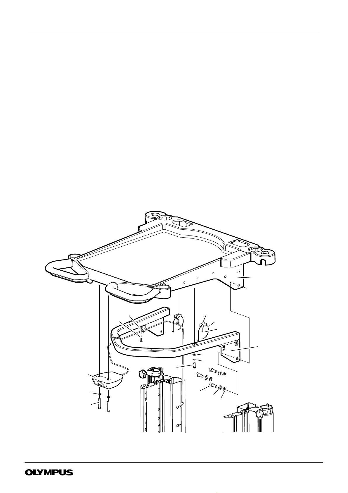
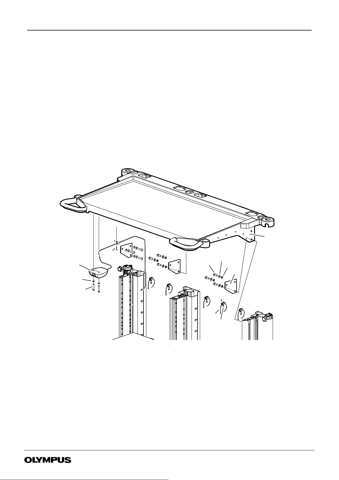
6 PART REPLACEMENT
6.1 General
The item numbers referred to throughout this Chapter are the same as those used in the Illustrated Parts List, Chapter 6.
To aid part replacement the following are available :
MAJ--198 WN--NP1 Sheft kit (Narrow) -- K10001429 MAJ--199 WN--WP1 Shelf kit (Wide) -- K10001430
Rear panel kit WM--NP1 K10005044 Rear panelkit WM--WP K10005041
Free castor kit K10004627 Braked castor kit K10004626
Castor free kit WM--P1 series A/S K10005041 Castor braked kit WM--P1 series A/S K10005040
Castor spanner WM--P1 series K10005023 Remote switch kit WM--P1 series K10005049
Umbilical/camera head holder kit K10006648
Before replacing any part on the workstation ensure that all mains power is disconnected.
Olympus will not be responsible for damage or injury to equipment or personnel, caused by unauthorised modification or
repair to this unit.
In the interests of safety and good maintenance ensure that fixings are tightened to the torque settings shown in the
parts list, illustrated parts list and part replacement chapter.
6.2 Blanking caps & Cable tidy replacement
(1) Refer to Figure 6-1. Blanking caps: Cable port (item 17), Monitor (item 18) and Scope pole (item 19) are a push fit and
so require to be carefully prised out of position.
(2) Unscrew Handknob (item 31) to release Cable tidy (item 29).
FIGURE 6-1
BLANKING CAPS & CABLE TIDY
37
21
2
50
2
47
17
2
20
2
67
2
31
18
19
2
2
29
6.3 Bracket twin LG holder replacement
(1) Refer to Figure 6-1 . and using 4mm hex drive tool bit remove Bracket twin LG holder (item 20) release two screws
(item 37) and washer crinkle (item 50) with washer (item 47) from jetnut (item 67).
(2) Replace/refit in reverse order. Using 4mm hex drive tool bit in torque driver ensure that screw (item 37) is tightened to a
torque of 6Nm.
WM--P1 SERIES WORKSTATIONS
Page 17 of 76
Issue 20 : July 2012
Page 18
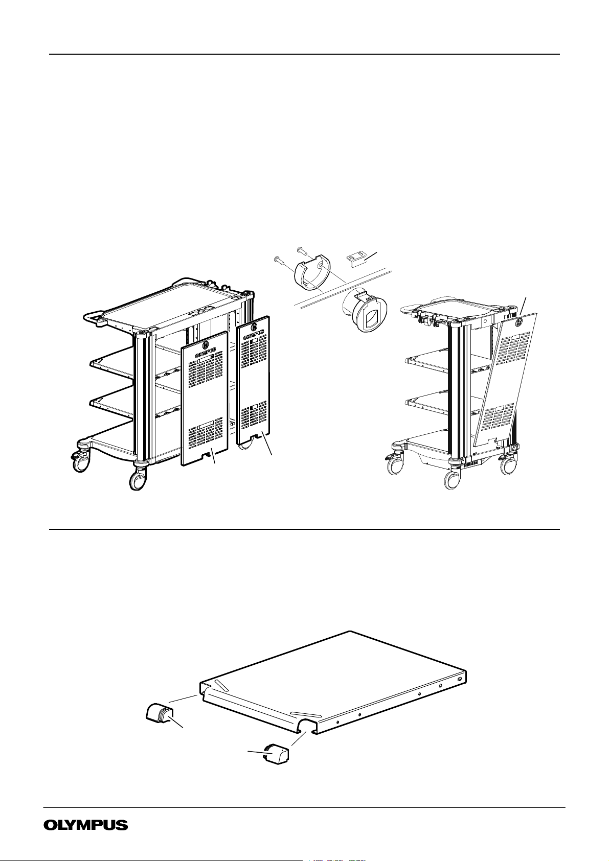
6.4 Rear panel replacement
Each Rear panel is available as a kit which inclues two feet and a finger latch pack. Fit the finger latch as shown in
Figure 6-2 and discard the keeper plate, if supplied.
WM--NP1 Rear panel -- part no K10005044. WM--WP1 Rear panel -- part no K10005045
(1) Refer to Figure 6-2, pull the finger latch to release the top of the rear panel.
(2) Lift the rear panel from the two studs on the base of the workstation.
(3) Refit /replace the rear panel.
FIGURE 6-2
REAR PANEL REPLACEMENT
Contents of
Finger latch pack
Discard
keeper plate
Finger
latch
WM--WP1
Rear panel
WM--NP1
Rear panel
6.5 Shelf corner moulding replacement
(1) Refer to Figure 6-3 each corner buffer (item 23 & 24) may be levered off.
(2) Reassemble by pushing each buffer into place.
24
23
FIGURE 6-3
SHELF CORNER MOULDINGS
WM--P1 SERIES WORKSTATIONS
Page 18 of 76
Issue 20 : July 2012
Page 19
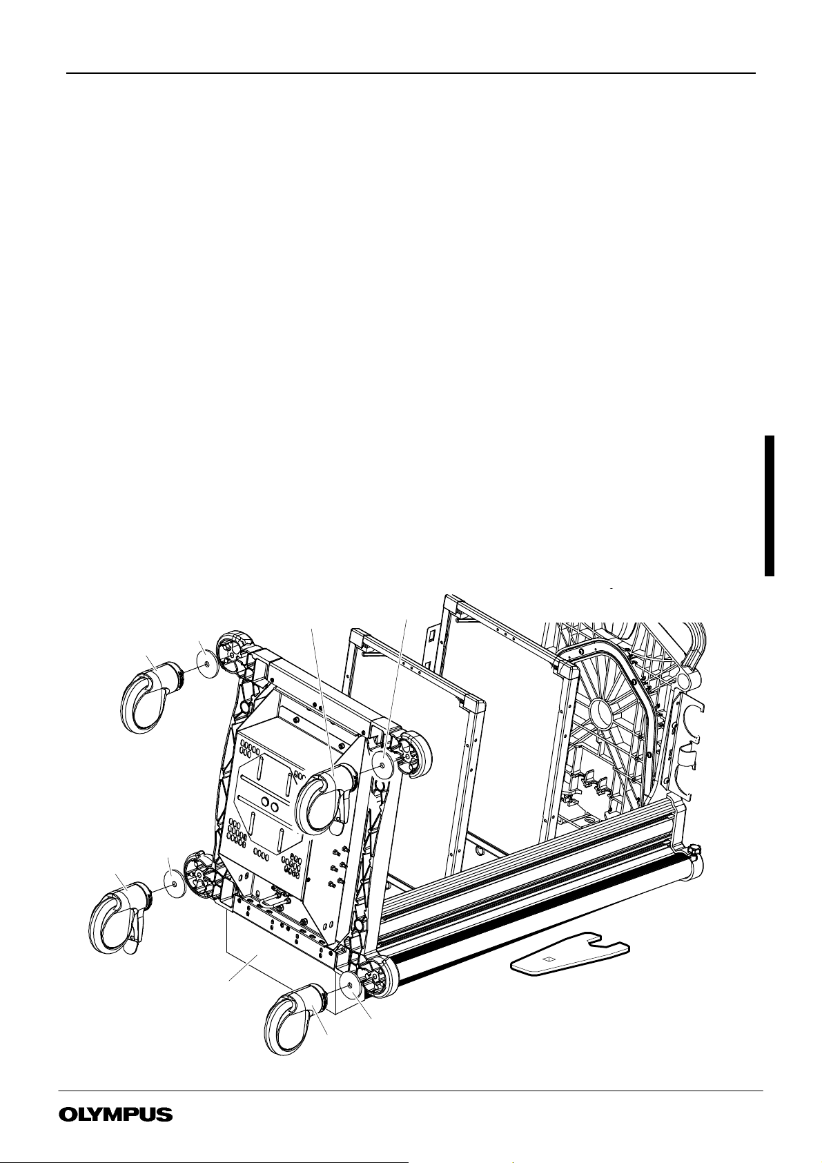
6.6 Castor replacement
Each workstation has two lockable castors (item 4) and two free castors (item 3).
Maintenance/Repair kits available:--
Free castor kit K10004627 Braked castor kit K10004626
Castor free kit WM--P1 series A/S K10005041 Castor braked kit WM--P1 series A/S K10005040
Special tool :
Castor spanner WM--P1 series K10005023
(1) Disconnect all power to the workstation.
(2) Remove rear panel and all equipment.
(3) Where fitted remove the scope pole or IV pole.
(4) Where fitted stow Keyboard Tray or Keyboard Arm -- Side Mounted.
(5) Remove the cable winder (item 19)
(6) Place the workstation carefully on to it’s back. The WM--DP1 exceeds 30Kg and must be handled by two people.
(7) Refer to Figure 6-4. For ease of access to the lower castors elevate and securely support the base end of the workstation.
(8) Using Castor spanner tool K10005023 fitted to a 1/2” drive wrench release the castor (item 3 or 4) and washer (item 5).
(9) Ensure that lockable castors(item 4) are refitted in the original location, refer to Figure 6-4
Run a M12 tap through the castor fixing hole to clear any residual Loctite adhesive.
When attaching a castor ensure that the thread of the bolt is smeared with loctite 243 ( item 60 ), use Castor spanner tool
K10005023 fitted to a torque driver to tighten to a torque of 30Nm.
NOTE If Castor spanner tool K10005023 is not used, then the torque value on the driver should be set to 38Nm.
Stand the workstation on it’s castors, re--install the equipment.
To allow the loctite to cure, the workstation should be kept in a location for 24 hours where the temperature is not below
22C and manouvering on bumpy surfaces is avoided.
4
LOCKABLE
3
5
5
Support
4
LOCKABLE
FIGURE 6-4
5
CASTOR SPANNER WM--P1SERIES -- K10005023
CASTOR REPLACEMENT
WM--P1 SERIES WORKSTATIONS
5
3
Page 19 of 76
Issue 20 : July 2012
Page 20

6.7 Remote switch replacement
(1) Unplug the Remote switch plug from the separation transformer.
(2) Refer to Figure 6-5 for WM--NP1, Figure 6-6 for WM--WP1 and Figure 6-7 for WM--DP1, use a No 2 Pozi drive tool to
release four screws (item 77) securing four p clips (item 78).
(3) Release the remote switch cable from releasable cable tie (item 34).
(4) Free the cable from the column side cable retainer.
(5) Using 4mm hex drive tool release two screws (item 40) with washer (item 50) to release remote switch (item 2).
(6) Reassemble in reverse order, use 4mm hex drive tool in torque wrench to tighten remote switch fixings to 2Nm.
(7) Fit four p clips to remote switch cable. Use a No 2 pozi driver in a torque wrench to fasten four screws (item 77) securing
four p clips (item 78) tighten to torque of 2.2Nm.
(8) Route the remote switch cable to releasable cable tie (item 34). Take up any slack in the cable toward the switch and
tighten the cable tie.
(9) Plug the Remote switch cable into the separation transformer.
(10) Route remaining cable into column side cable retainer.
WM--P1 SERIES WORKSTATIONS
Page 20 of 76
Issue 20 : July 2012
Page 21
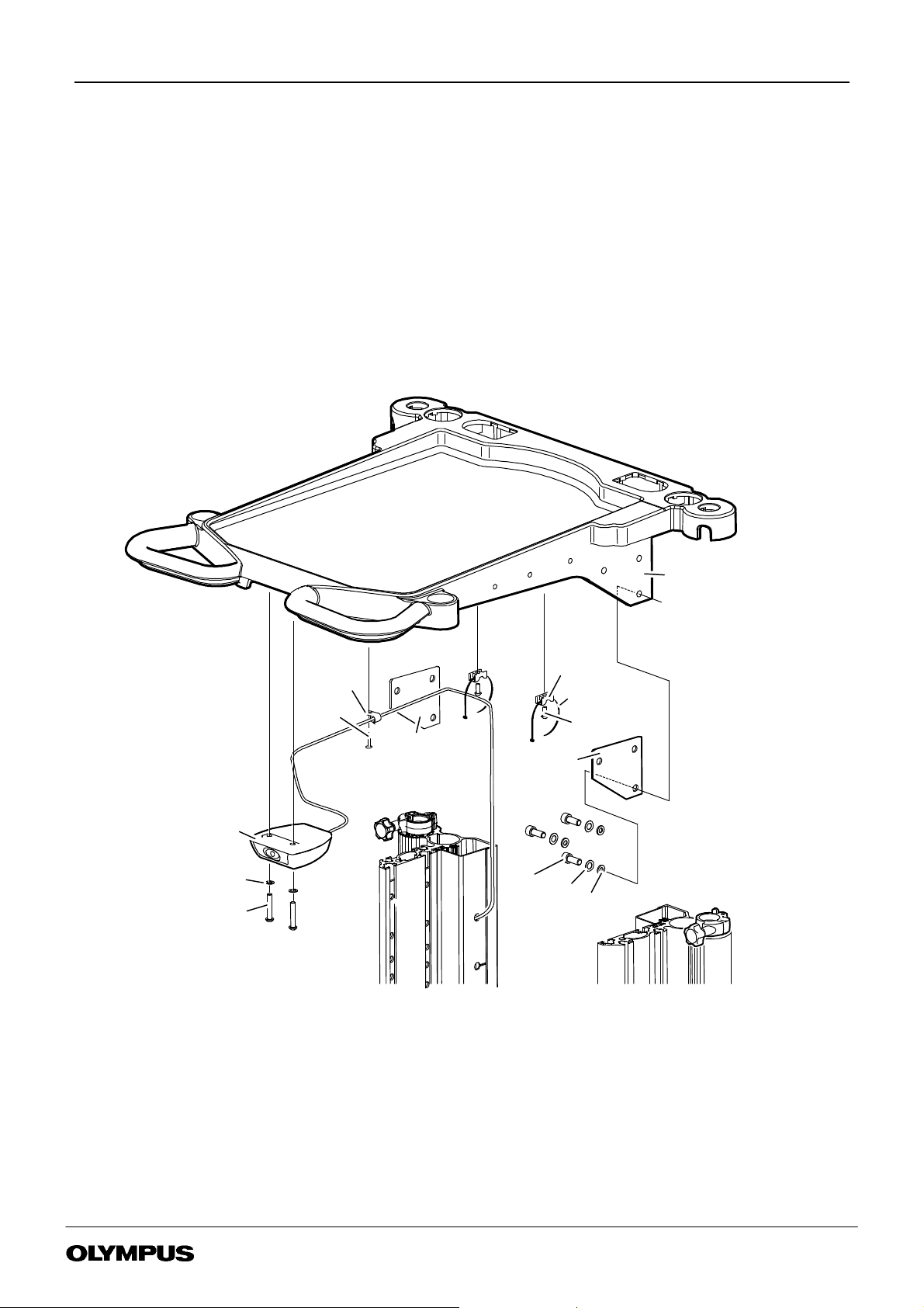
6.8 Top Tray replacement WM- N P1
(1) Remove all equipment from the top tray (item 14)
(2) Refer to Section 6.7 and remove the Remote switch assembly and cable (item 2) from the top tray.
(3) Refer to Figure 6-5 to release Support plates WM--DP1 (item 10) and Top tray (item 14). Using a 6mm allen key unscrew
six screws (item 75) with washer crinkle (item 49) and washer (item 45).
(4) Reassemble in reverse order . Place top tray assembly into place between the side columns. Position each Support plate
WM--DP1 (item 10) insert but do not fully tighten, three screws (item 75) with washer crinkle (item 49) and
washer (item 45) using 6mm hex drive tool. Using 6mm hex drive tool in torque wrench fully tighten to 20Nm.
(5) Refer to section 6.7 to refit remote switch.
FIGURE 6-5
WM--NP1 REMOTE SWITCH &
TOP TRAY REPLACEMENT
50
40
14
32
77
78
42.2Nm
4
34
42
2
2
22Nm
10
10
2
75
2
22Nm
6 20Nm
49
6
45
6
WM--P1 SERIES WORKSTATIONS
Page 21 of 76
Issue 20 : July 2012
Page 22
6.9 Top Tray replacement WM- WP1
(1) Remove all equipment from the top tray (item 14)
(2) Refer to Section 6.7 and remove the Remote switch assembly and cable (item 2) from the top tray.
(3) Refer to Figure 6-6. Using a 6mm allen key unscrew six screws (item 75) with washer crinkle (item 49) and
washer (item 45).
(4) Remove and invert the top tray. Using a 6mm allen key relaese four screws (item28) with washer (item 50) and crinkle
washer (item 45). Separate the Top tray (item 14) from Support top tray wide (item 15).
(5) Reassemble in reverse order. Secure top tray (item 14) to Top tray support wide (item 15) using a 6mm allen key to
fasten four screws (item 28) with washer (item 50) and crinkle washer (item 47) Do not fully tighten.
(6) Place top tray assembly into place between the side columns. Using 6mm hex drive tool in torque wrench tighten six
screws (item 75) with washer crinkle (item 49) and washer (item 45) to 20Nm.
(7) Fully tighten four screws (item 28) securing support toptray narrow to top tray using 6mm hex drive tool in torque wrench
to 4Nm
(8) Refer to section 6.7 to refit remote switch.
FIGURE 6-6
WM--WP1 REMOTE SWITCH & TOP
TRAY REPLACEMENT
14
77
78
42.2Nm
4
32
2
34
2
42
22Nm
15
47
4
50
4
38
2
44Nm
50
2
40
22Nm
WM--P1 SERIES WORKSTATIONS
75
6 20Nm
49
6
45
6
Page 22 of 76
Issue 20 : July 2012
Page 23
6.10 Top Tray Replacement WM- DP1
(1) Remove all equipment from the top tray (item 14)
(2) Refer to Section 6.7 and remove the Remote switch assembly and cable (item 2) from the top tray.
(3) Refer to Figure 6-7 to release Support plates WM--DP1 (item 10) and Top tray (item 14). Using a 6mm allen key unscrew
nine screws (item 75) with washer crinkle (item 49) and washer (item 45).
(4) Reassemble in reverse order. Place top tray assembly into place between the side columns. Position each Support plate
WM--DP1 (item 10) insert but do not fully tighten, three screws (item 75) with washer crinkle (item 49) and
washer (item 45) using 6mm hex drive tool. Using 6mm hex drive tool in torque wrench fully tighten to 20Nm.
(5) Refer to section 6.7 to refit remote switch.
FIGURE 6-7
WM--DP1 REMOTE SWITCH AND TOP
TRAY REPLACEMENT
50
40
78
4
77
42.2Nm
2
75
92Nm
49
9
45
9
14
10
2
22Nm
34
32
5
42
5
5
WM--P1 SERIES WORKSTATIONS
Page 23 of 76
Issue 20 : July 2012
Page 24

6.11 Shelf replacement
Shelf kits : -- MAJ--198 WM--NP1 SHELF KIT (NARROW) -- K10001429
MAJ--199 WM--WP1 SHELF KIT (WIDE) -- K10001430
(1) To remove shelf (item 22) refer to Figure 6-8.
(2) If the shelf is to be refitted at the same height make carefull note of the fixing holes used.
(3) Using 6mm hex drive tool bit in power torque tool release four screws (item 36) with washer crinkle (item 49) and washer
(item 43).
(4) Reassemble ensuring that the fixings are tightened to a torque of 15Nm.
FIGURE 6-8
SHELF REPLACEMENT
33
3
38
26Nm
50
36
4 15Nm49
43
2
47
2
25
22
2
4
4
67
WM--P1 SERIES WORKSTATIONS
Page 24 of 76
Issue 20 : July 2012
Page 25

6.12 Scope pole clamp P1 series
(1) Refer to Figure 6-1. Blanking caps : Cable port (item 17), Monitor (item 18) and Scope pole (item 19) are a push fit and
so require to be carefully prised out of position.
(2) Refer to Figure 6-9 Unscrew Handknob (item 6) to release Cable tidy (item 29).
(3) Remove the top tray, refer to section 6.8 for WM--NP1,section 6.9 for WM--WP1 and section 6.10 for WM--DP1.
(4) Refer to Figure 6-9 Use a pozi screwdriver to release screw (item 41) with washer (item 48) and remove Scope Pole
Clamp Assy (item 46).
(5) Refit in reverse order ensuring that Screw (item 41) is tightend to 2.5Nm using a No2 pozi drive tool bit in powered torque
tool.
(6) Refit remaining parts in reverse order.
12
28
4
46
2
8
41
48
29
SCOPE POLE CLAMP, SCOPE POLE
FIGURE 6-9
RUNNERS & NUT STRIPS
7
6
2
13
8
6.13 Runner- scope pole P1 series
(1) Refer to section 5.11 to remove scope pole clamp P1 series.
(2) Lift each runner from it’s slot in the side column.
(3) Re fit in reverse order.
6.14 Nutstrip P1 series
(1) Remove the top tray refer to section 5.8 for WM--NP1, section 5.9 for WM--WP1 and section 5.10 for WM--DP1
(2) Refer to Figure 6-9 and remove Nutstips (item 12) noting which side of the nutstrip is facing outward.
(3) Replace/refit in reverse order.
WM--P1 SERIES WORKSTATIONS
Page 25 of 76
Issue 20 : July 2012
Page 26

6.15 Power cable replacement
The power cable (item 58) may be replaced while the transformer is within the workstation.
(1) Disconnect from mains power supply.
(2) Disconnect the power cable from the transformer.
(3) Disconnect output cables.
(4) Refer to Figure 6-10. Using a short No 2 Pozidrive screwdriver release the four screws from cable clamps.
FIGURE 6-10
POWER CABLE CLAMP
(5) Position a new power cable to ensure that the input connector cable end is 30cm from the clamp.
(6) T ighten one clamp sufficient to ensure that a firm pull on the power cable is not trasmitted to the loop between the clamp
and the input connector. Tighten the second clamp a similar amount to the first.
6.16 Separation Transformer replacement
Refer to Transformers for Mobile Workstations Maintenance & Repair Manual part no: K5070505
CAUTION
The Separation Transformer weighs up to 30 kg, take care when lifting.
It is recommended that two people are involved in the disassembly and reassembly of the Separation Transformer.
WM--P1 SERIES WORKSTATIONS
Page 26 of 76
Issue 20 : July 2012
Page 27

Chapter 7 Illustrated Parts List
Table of Contents
7.1 WM--NP1, WM--WP1 & WM--DP1 Mobile Workstation 28.........................
Page
WM--P1 SERIES WORKSTATIONS
Page 27 of 76
Issue 20 : July 2012
Page 28

7 ILLUSTRATED PARTS LIST
7.1 WM- N P1, WM- WP1 &WM-DP1 MOBILE WORKSTATION
93
ITEM
FIGURE 7-1
WM--NP1 & WM--WP1 PART LOCATION
93/1
93/2
21
20
93/4
37
93/5
26Nm
93/3
50
2
47
17
2
19
18
2
2
29
16
2
67
2
54
27
26
88
2
WM--DP1 -- 4
WM--P1 SERIES WORKSTATIONS
88
55
Page 28 of 76
Issue 20 : July 2012
Page 29

49
92
FIGURE 7-2
WM--DP1 PART LOCATION
26
WM--NP1
26
4
91
4
4
83
WM--WP1
FIGURE 7-3
WM--NP1 PART LOCATION
14
10
32
77
78
42.2Nm
4
34
42
2
2
22Nm
10
2
50
2
40
22Nm
WM--P1 SERIES WORKSTATIONS
75
6 20Nm
49
6
45
6
Page 29 of 76
Issue 20 : July 2012
Page 30

FIGURE 7-4
WM--WP1 PART LOCATION
14
50
40
77
78
42.2Nm
4
32
2
34
2
42
22Nm
15
47
4
50
4
38
2
2
22Nm
44Nm
75
6 20Nm
49
6
45
6
FIGURE 7-5
WM--DP1 PART LOCATION
78
77
2
50
2
40
22Nm
WM--P1 SERIES WORKSTATIONS
4
42.2Nm
75
92Nm
34
32
5
49
42
5
45
5
14
9
9
10
Page 30 of 76
Issue 20 : July 2012
Page 31

38
26Nm
50
FIGURE 7-6
WM--NP1 & WM--WP1 PART LOCATION
33
36
4 15Nm49
43
2
47
2
25
22
2
4
4
3
24
67
2
88
23
2
WM--P1 SERIES WORKSTATIONS
Page 31 of 76
Issue 20 : July 2012
Page 32

12
28
4
46
48
2.5Nm
WM--NP1 & WM--WP1 PART LOCATION
2
8
7
FIGURE 7-7
41
6
2
13
8
11
1
45
52
4
4 15Mm
32
4
2 30Nm/38Nm
60
86
34
5
A/R
4
4
4
11
11
5
2
3
2 30Nm/38Nm
60
A/R
2
WM--P1 SERIES WORKSTATIONS
Page 32 of 76
Issue 20 : July 2012
Page 33

WM- NP1 100V JP p/no K10000284 WM- DP1 100V JP p/no K10003725
WM- NP1 110- 120V US p/no K10000285 WM- DP1 110- 120V US p/no K10003726
WM- NP1 220- 240V UK A/S p/no K10000286 WM- DP1 220- 240V UK A/S p/no K10003727
WM- NP1 220- 240V EU p/no K10000287 WM- DP1 220- 240V EU p/no K10003728
WM- NP1 220- 240V ROW p/no K10000288 WM- DP1 220- 240V ROW p/no K10003729
WM- NP1 220- 240V EU- A/S p/no K10004412
WM- NP1 A/S p/no K10004537
WM- WP1 100V JP p/no K10001332
WM- WP1 110-120V US p/no K10001333
WM- WP1 220- 240V UK A/S p/no K10001334
WM- WP1 220- 240V EU p/no K10001335
WM- WP1 220- 240V ROW p/no K10001336
WM- WP1 220- 240V EU- A/S p/no K10004413
WM- WP1 A/S p/no K10004538
Item Description Part No Qty
1 MAJ--173 TRANSFORMER WM--T1 100V .............. K10006316 1 -- Packaged
K10000289 1 -- JP
MAJ--174TRANSFORMER ........................ K10006317 1 -- Packaged
K10000290 1 -- US
MAJ--175 TRANSFORMER WM--T1 220--240V .......... K10006318 1 -- Packaged
K10000291 1 -- UK, EU,ROW
BALLAST WEIGHT ASSEMBLY ...................... K10004504 1 -- N, NS
2 REMOTE SWITCH WM--260 ASSY ................... K7504585 1 -- V
3 CASTOR--FREE ................................. -- 2 -- L,BB
CASTOR--FREE(ANTISTATIC) ...................... K10004419 2 -- N,P, U, BB
4 CASTOR--BRAKED ............................... -- 2 -- M,BB
CASTOR--BRAKED (ANTISTATIC) .................... K10004420 2 -- N,P, T, BB
5 WASHERCASTOR5mmTHICK ..................... K7505795 4 -- L, M
6 HANDKNOB BLACK M6 K3921470 1 --
7 WASHER M6 K3921292 1 --
8 SCOPE POLE CLAMP P1 SERIES K7506327 1
9SPARE
10 PLATESSUPPORTWM--DP1 ...................... K10006102 NP1--2. DP1--3 -- --
11 BUMPERCORNERWRAP ......................... K10001042 4 -- --
12 NUTSTRIPP1SERIES............................ K10000089 4 -- --
13 RUNNER--SCOPE POLE P1 SERIES ................. K10008227 8 -- --
14 TOPTRAYWM--NP1SERIES ....................... K10000088 1 -- NP1, Z
TOPTRAYWM--WP1SERIES....................... K10003423 1 -- WP1
TOPTRAYWM--DP1SERIES ....................... K10005448 1 -- DP1
15 SUPPORTTOPTRAYWIDE........................ K10001312 1 -- WP1
16 INSERT ROUND RIBBED ......................... K10003374 1 -- --
Torque
Remarks
spare JP
spare US
spare UK, EU,
ROW
WM--P1 SERIES WORKSTATIONS
Page 33 of 76
Issue 20 : July 2012
Page 34

Item Description Part No Qty
17 BLANKINGCAPCABLEPORTWM--260 ............... K7503929 -- -- C
18 BLANKINGCAPMONITORWM--260.................. K7504466 -- -- C
19 BLANKINGCAPSCOPEPOLEWM--260............... K7504468 -- -- C
20 CONNECTORHOLDERBRACKET ................... K10001392 1 -- W
21 CONNECTORHOLDERWM--P1SERIES .............. K10000054 2 -- W
22 SHELFWM--NP1SERIES.......................... K10000203 2 -- R, NP1, DP1
SHELFWM--WP1SERIES ......................... K10001307 2 -- S, WP1,DP1
23 CORNERBUFFER--SHELFR/H .................... K10001123 2 -- R, S
24 CORNERBUFFER--SHELFL/H..................... K10001124 2 -- R, S
25 WATERBOTTLEBRACKET ........................ K7503823 1 -- --
26 REARDOORWM--NP1SERIES ..................... -- 1 -- H
REARDOORWM--WP1SERIES..................... -- 1 -- J
27 LATCHSPAREFORWM--*P1RANGE ............... K10016172 1 -- H, J
28 RETAINERCABLECO--EXTRUSION ................. K7506066 2 -- --
29 CABLEHANGER--WITHPIN ....................... K10001377 -- -- C
30 SPARE
31 SPARE
32 CABLETIEMOUNTINGCRADLE .................... K10003392 6 -- --
33 CABLE CLIP RELEASABLE NYLON .................. 3920309 NP1, WP1--6.
DP1--14
34 CABLE TIE REL 4.8W x 200L BLACK ................. K3921530 -- -- C
35 SPARE
36 SCREWM8x16HEXSKTCAPHD .................. K3921515 NP1, WP1--8.
DP1--16
37 SCREWM6x25HEXSKTBUTTHD ................. 3920369 2 6Nm W
38 SCREWM6x12HEXSKTBUTTHD ................. 3920326 NP1--2
WP1--6
39 SCREWM6x20THREADFORMING PANHD ......... K10006549 8 -- DP1
40 SCREWM6x35HEXSKTBUTTHD ................. 3050858 2 2Nm --
41 SCREW 4.2 x 32 POZI PAN HD SELF TAPPING ......... K3921389 2 -- --
42 SCREW M6 x 12 SELF TAPPING .................... K10003437 2 -- --
43 WASHER24OD................................. K3921536 8 -- R, S
44 SPARE
45 WASHERM8 ................................... 3920372 10, DP1--15 -- Y
46 SCOPE POLE CLAMP ASSEMBLY .................. K10006167 2 -- --
47 WASHERM6 ................................... 3920333 4, DP1--14 -- W
48 WASHERM4 ................................... 3072461 2 -- --
49 WASHERCRINKLEM8 ........................... K3920997 NP1, WP1--14,
DP1--31
50 WASHERCRINKLEM6 ........................... 3072622 NP1, WP1--6
DP1--16
51 NUTM6 ....................................... 3920335 10 -- DP1
52 NUTM8NYLOCST.ST............................ K10006624 4 15Nm --
53 SPARE
54 FOOTSELFADHESIVE ........................... 3116247 2 -- --
Torque
-- R , S
15Nm R, S
-- A , B
-- R , S , Y
-- W
Remarks
WM--P1 SERIES WORKSTATIONS
Page 34 of 76
Issue 20 : July 2012
Page 35

Item Description Part No Qty
55 FOOTPUSH--IN ................................. K10003425 NP1, WP1--2
DP1--4
56 POWERCABLEUNIVERSALIEC3200.8M............. K3921014 -- -- C
57 POWERCABLEUNIVERSALIEC320................. K3921015 -- -- JP, UK, EU,C
58 POWER CABLE JAPAN HOSP GRADE -- IEC320.C19 ..... K10001001 1 -- JP
POWERCABLEU.S. ............................ K10001002 1 -- US
CABLE U.K. 13A -- IEC320.C19 K10001003 1 -- UK
POWER CABLE SCHUKO -- IEC320.C19 ............... K10001004 1 -- EU
POWER CABLE FLYING LEADS -- IEC320.C19 .......... K10001005 1 -- ROW
59 SPARE
60 LOCTITE243 ................................... 3001857 A//R -- L, M
61 SPARE
62 SPARE
63 L--WRENCHBALLDRIVE6MMA/F................... K3921444 1 -- C, R, S
64 INSTRUCTIONS WM--P1 SERIES JP ................ K10000545 1 -- JP
INSTRUCTIONS WM--P1 SERIES ................... K10003436 1 -- US, UK, EU,
INSTRUCTIONS WM--P1 SERIES A/S ................. K10004838 1 -- N, P
INSTRUCTIONS WM--DP1 ......................... K10005955 1 -- US, UK, EU,
65 WARRANTY CARD (JAPANESE) .................... 5041015 1 -- JP
66 NYLONCABLETIE .............................. 3006026 1 -- --
67 JETNUTM6SINGLENUTPLATE .................... 3920573 4 -- W
68 CABLEUNIVERSALIEC2.5M ...................... K10000449 1 -- WP1 E, G
69 SPARE
70 SPARE
71 SPARE
72 SPARE
73 SPARE
74 SPARE
75 SCREWM8x25HEXSKTBUTTHD ................. K10003945 NP1, WP1--6.
DP1--9
77 SCREW4.2x12.7POSIPANST .................... K10004107 4 2.2Nm --
78 P--CLIPID4.8NYLONBLACK ...................... K10001199 4 -- --
79 VELCRO20mmONEWRAPBLACK .................. K10003972 0.46 -- --
80 SUCTIONTUBECLIPS ........................... K3921393 10 -- JP, C
81 ADAPTORCABLEIEC--JAPAN/U.S. .................. K3921594 2 -- JP, C
82 INSTRUCTIONS FOR USE MAJ--150 ................ K5070401 1 -- C
83 GROMMET22.2MMCABLEHOLE .................. K10005673 1 -- DP1
84 SPARE
85 SPARE
86 SCREWM6x10HEXSKTBUTTHD ................. K3921284 NP1, WP1--4
DP1--6
88 LABEL -- CAUTION ANTI S TATIC .................... K10004445 NP1, WP1--5
DP1--10
Continued
Torque
-- H , J
-- --
-- --
-- N , P
Remarks
ROW
ROW
WM--P1 SERIES WORKSTATIONS
Page 35 of 76
Issue 20 : July 2012
Page 36

Item Description Part No Qty
89 ACCESSORY KIT FOR WM--NP1 UK EU ROW .......... K10004462 1 -- --
CABLE HANGER -- WITH PIN K10001377 3 -- --
CABLE UNIVERSAL IEC 320 0.8M K3921014 5 -- --
CABLE UNIVERSAL IEC 320 K3921015 1 -- --
INSTRUCTIONS WM--P1 SERIES ENG K10003436 1 -- --
ACCESSORY KIT FOR WM--WP1 UK,EU,ROW ......... K10004466 1 -- --
CABLE HANGER -- WITH PIN K10001377 2 -- --
CABLE UNIVERSAL IEC 320 0.8M K3921014 3 -- --
CABLE UNIVERSAL IEC 320 K3921015 5 -- --
CABLE UNIVERSAL IEC 320 M--FEM 2.5m K10000449 2 -- --
INSTRUCTIONS WM--P1 SERIES ENG K10003436 1 -- --
ACCESSORY KIT WM--NP1 100V JP ................ K10004488 1 -- --
CABLE HANGER -- WITH PIN K10001377 2 -- --
CABLE UNIVERSAL IEC 320 0.8M K3921014 3 -- --
CABLE UNIVERSAL IEC 320 K3921015 4 -- --
INSTRUCTIONS WM--P1 SERIES JP K10000545 1 -- --
SUCTION TUBE CLIPS K3921393 10 -- --
ADAPTOR CABLE IEC--JAPAN/U.S. K3921594 1 -- --
INSTRUCTIONS FOR USE MAJ--150 K5070401 2 -- --
ACCESSORY KIT WM--NP1 100V--120V US ........... K10004489 1 -- --
CABLE HANGER -- WITH PIN K10001377 2 -- --
CABLE UNIVERSAL IEC 320 0.8M K3921014 3 -- --
CABLE UNIVERSAL IEC 320 K3921015 5 -- --
ADAPTOR CABLE IEC--JAPAN/U.S. K3921594 2 -- --
INSTRUCTIONS WM--P1 SERIES ENG K10003436 1 -- --
INSTRUCTIONS FOR USE MAJ--150 K5070401 2 -- --
ACCESSORY KIT 1332 WM--WP1 100V JP ............ K10004498 1 -- --
CABLE HANGER -- WITH PIN K10001377 2 -- --
CABLE UNIVERSAL IEC 320 0.8M K3921014 3 -- --
CABLE UNIVERSAL IEC 320 K3921015 5 -- --
INSTRUCTIONS WM--P1 SERIES JP K10000545 1 -- --
SUCTION TUBE CLIPS K3921393 10 -- --
ADAPTOR CABLE IEC--JAPAN/U.S. K3921594 2 -- --
INSTRUCTIONS FOR USE MAJ--150 K5070401 1 -- --
CABLE UNIVERSAL IEC 320 M--FEM 2.5m K10000449 1 -- --
ACCESSORY KIT 1333 WM--WP1 110--120V US ........ K10004499 1 -- --
CABLE HANGER -- WITH PIN K10001377 2 -- --
CABLE UNIVERSAL IEC 320 0.8M K3921014 3 -- --
CABLE UNIVERSAL IEC 320 K3921015 5 -- --
INSTRUCTIONS WM--P1 SERIES ENG K10003436 1 -- --
ADAPTOR CABLE IEC--JAPAN/U.S. K3921594 2 -- --
INSTRUCTIONS FOR USE MAJ--150 K5070401 2 -- --
CABLE UNIVERSAL IEC 320 M--FEM 2.5m K10000449 2 -- --
Continued
Torque
Remarks
WM--P1 SERIES WORKSTATIONS
Page 36 of 76
Issue 20 : July 2012
Page 37

Item Description Part No Qty
ACCESSORY KIT FOR WM--N/WP1 (NON--TX) .......... K10004791 1 -- --
CABLE HANGER -- WITH PIN K10001377 2 -- --
INSTRUCTIONS WM--P1 A/S K10004834 1 -- --
ACCESSORY KIT FOR WM--NP1 EU--A/S ............. K10004832 1 -- --
CABLE HANGER -- WITH PIN K10001377 2 -- --
CABLE UNIVERSAL IEC 320 0.8M K3921014 3 -- --
CABLE UNIVERSAL IEC 320 K3921015 5 -- --
INSTRUCTIONS WM--P1 A/S K10004834 1 -- --
ACCESSORY KIT FOR WM--WP1 EU--A/S ............. K10004833 1 -- --
CABLE HANGER -- WITH PIN K10001377 2 -- --
CABLE UNIVERSAL IEC 320 0.8M K3921014 3 -- --
CABLE UNIVERSAL IEC 320 K3921015 5 -- --
CABLE UNIVERSAL IEC 320 M--FEM 2.5m K10000449 2 -- --
INSTRUCTIONS WM--P1 A/S K10004834 1 -- --
ACCESSORY KIT FOR WM--DP1 UK EU ROW .......... K10005985 1 -- --
BLANKING CAP CABLE PORT WM--260 K7503929 2 -- --
BLANKING CAP MONITOR WM--260 K7504466 1 -- --
CABLE HANGER -- WITH PIN K10001377 2 -- --
CABLE UNIVERSAL IEC 320 K3921015 4 -- --
CABLE UNIVERSAL IEC 320 M--FEM 2.5m K10000449 4 -- --
INSTRUCTIONS WM --DP1 ENG K10005955 1 -- --
BLISTER PACK ASSY WM--P1 K10006169 1 -- --
BLANKING CAP CABLE PORT WM--260 K7503929 2 -- --
BLANKING CAP MONITOR WM--260 K7504466 2 -- --
BLANKING CAP SCOPE POLE WM--260 K7504468 2 -- --
CABLE TIE REL 4.8Wx200L BLACK K3921530 6 -- --
L--WRENCH BALL DRIVE 6MM A/F K3921444 1 -- --
ACCESSORY KIT WM--DP1 110-- 120V US ............. K10005986 1 -- --
BLANKING CAP CABLE PORT WM--260 K7503929 2 -- --
BLANKING CAP MONITOR WM--260 K7504466 1 -- --
CABLE HANGER -- WITH PIN K10001377 2 -- --
CABLE UNIVERSAL IEC 320 K3921015 4 -- --
INSTRUCTIONS WM --DP1 ENG K10005955 1 -- --
ADAPTOR CABLE IEC--JAPAN/U.S. K3921594 2 -- --
INSTRUCTIONS FOR USE MAJ--150 K5070401 1 -- --
CABLE UNIVERSAL IEC 320 M--FEM 2.5m K10000449 4 -- --
BLISTER PACK ASSY WM--P1 K10006169 1 -- --
BLANKING CAP CABLE PORT WM--260 K7503929 2 -- --
BLANKING CAP MONITOR WM--260 K7504466 2 -- --
BLANKING CAP SCOPE POLE WM--260 K7504468 2 -- --
CABLE TIE REL 4.8Wx200L BLACK K3921530 6 -- --
L--WRENCH BALL DRIVE 6MM A/F K3921444 1 -- --
Torque
Remarks
Continued
WM--P1 SERIES WORKSTATIONS
Page 37 of 76
Issue 20 : July 2012
Page 38

Item Description Part No Qty
90 SPARE
91 NUTM8DOMEDNATURALNYLON .................. K10006640 1 -- DP1
92 SPACER18MMODx8.2MMIDx5MMLG ............. K10006641 1 -- DP1
93 LIMITER--FRONT(MAJ--181)...................... K10007121 1 -- DP1, Y
94 LIMITER REAR (MAJ--181) ......................... K10007122 2 -- Y
95 SCREWM8x50SKTCAPHD ...................... 3050998 2 -- Y
96 PAINT -- WHITE KEYMED SPEC 74 .................. K10006564 400ML -- --
97 PAINT -- LILAC KEYMED SPEC 76 ................... K10006565 400ML -- --
REMARKS
A Tighten to 4Nm when used to secure item 15, Support Top Tray. Ref figure 6--1
B Tighten to 6Nm when used to secure item 25, Water Bottle Bracket. Ref figure 6--3
C Supplied in ACCESSORY KIT WM--NP1 100V JP K10004488
D Supplied in ACCESSORY KIT WM--NP1 100V--120V US K10004489
E Supplied in ACCESSORY KIT 1332 WM--WP1 100V JP K10004498
F Supplied in ACCESSORY KIT 1333 WM--WP1 110--120V US K10004499
G Supplied in ACCESSORY KIT FOR WM--WP1 UK,EU,ROW K10004466
H Supplied in REAR PANEL KIT WM--NP1 K10005044
J Supplied in REAR PANEL KIT WM--WP1 K10005045
L Supplied in FREE CASTOR KIT -- WM--P1 SERIES ( NON A/S ) K10004627
M Supplied in BRAKED CASTOR KIT ( NON A/S ) K10004626
N Used on WM--NP1 A/S & WM--WP1 A/S ( and all UK after Oct 07)
P Used on WM--NP1 220--240V EU--A/S & WM--WP1 220--240V EU--A/S (and all UK after Oct 07)
R Supplied in MAJ--198 WM--NP1 SHELF KIT (NARROW) K10001429
S Supplied in MAJ--199 WM--WP1 SHELF KIT (WIDE) K10001430
T Supplied in CASTOR BRAKED KIT WM--P1 SERIES A/S K10005040
U Supplied in CASTOR FREE KIT WM--P1 SERIES A/S K10005041
V Supplied in REMOTE SWITCH KIT WM--P1 SERIES K10005049
W Supplied in UMIBILICAL/CAMERA HEAD HOLDER KIT K10006648
Y Supplied in LIMITER -- MOVEMENT ( MAJ--181 ) K10007108 Contents :--
93/1LIMITERFRONT(MAJ--181) .................... K10007121
93/2LIMITERREAR(MAJ--181)...................... K10007122
93/3SCREWM8x50 .............................. 3050998
93/4WASHERCRINKLEM8 ......................... K3920997
93/5WASHERM8................................. 3920372
93/6 INSTRUCTIONS LIMITERS FOR MAJ-- 181 ........... K10008095
Z Early models of WM--NP1 were fitted with a ’Support T op Tray’ ( item 15). On later models a redesigned top tray reduced
the support required to; 2, PLATES SUPPORT WM--DP1, item 10, p/no K10006102.
The early model top tray is no longer available and a current top tray and plates support must be used. The ’Support Top
Tray’ ( item 15) cannot be used and should be discarded.
AA Oct 2007 -- all UK workstations now supplied fitted with antistatic castors.
BB Refer to Chapter 6.6 for torque tightening figures.
NS Not Shown
Torque
Remarks
WM--P1 SERIES WORKSTATIONS
Page 38 of 76
Issue 20 : July 2012
Page 39

Chapter 8 Accessories Illustrated Parts List
Table of Contents
8.1 MAJ--155 Universal display arm --LCD 40.....................................
8.2 MAJ--179 Keyboard tray sliding 41..........................................
8.3 MAJ--180 Keyboard arm -- side mounted 43...................................
8.4 MAJ--181 LCD monitor arm 45............................................
8.5 MAJ--183 Scope pole kit 48...............................................
8.6 MAJ--185 Universal stowage container 49....................................
8.7 MAJ--187 IV pole kit 50..................................................
8.8 MAJ--188 / MAJ--1614 CO
8.9 MAJ--190 Equipment support rail 52.........................................
8.10 MAJ--192 Side shelf 53..................................................
8.11 MAJ--195 Cable retaining hook 53..........................................
8.12 MAJ--193, 194, 1611 & 1612 Lockable drawer 54...............................
8.13 MAJ--196 Rear/front panel kit 56...........................................
8.14 MAJ--198 WM--NP1 Shelf kit (Narrow)
MAJ--199 WM--WP1 Shelf kit (Wide) 57......................................
8.15 MAJ--1600 14” CRT bracket kit
MAJ--1601 14” CRT bracket kit wide
MAJ--1602 20” CRT bracket kit wide 58......................................
8.16 MAJ--1609 LCD Arm --adjustable 59........................................
8.17 MAJ--1610 LCD Manoeuvring handle 61.....................................
8.18 MAJ--1613 Universal display arm (CRT) 62....................................
8.19 MAJ--1620 14” CRT mount (Narrow)
MAJ--1621 20” CRT mount (Narrow)
MAJ--1622 14” CRT mount (Wide)
MAJ--1623 20” CRT mount 64.............................................
8.20 MAJ--1624 Nurses control panel arm 66......................................
8.21 MAJ--1625 EUM30 keyboard 67...........................................
8.22 MAJ--1626 EUS arm mount 68............................................
8.23 MAJ--1627 EU--C60\200 shelf kit 69.........................................
8.24 MAJ--1628 Nurses control panel arm 71......................................
8.25 MAJ--1630 Video/Scope cable bracket 73.....................................
8.26 MAJ--1631 Plug block kit -- EU 74..........................................
8.27 MAJ--1635 MAJ--1635 EUS Connector holder 75...............................
cylinder bracket kit 51..............................
2
Page
WM--P1 SERIES WORKSTATIONS
Page 39 of 76
Issue 20 : July 2012
Page 40

8 ILLUSTRATED PARTS LIST - ACCESSORIES
8.1 MAJ- 155 UNIVERSAL DISPLAY ARM - LCD
FIGURE 8-1
5
26
23
24
2
2
2
27
4
13
33
9
15
MAJ- 155 UNIVERSAL DISPLAY ARM - LCD p/no K7505210
Item Description Part No Qty
1 BRACKET--UNIVERSALDISPLAYLCD ................... K7505259 1 -- --
2--4 SPARE
5 MAJ--132LCDBRACKET ............................. K7504769 1 -- --
6SPARE
7 BOLTCOACHM10x75L ............................. K3921545 1 -- A, NS
8SPARE
9 FOOT ........................................... 3021521 1 -- --
10, 11 SPARE
12 NUTNORMALM10 ................................. 3038564 1 -- A, NS
13 M10PROTECTIONCAP.............................. K3921359 1 -- --
14 CABLE TIE RELEASABLE ............................ K3921530 4 -- NS
15 HANDLE ADJUSTABLE LEVER FEMALE .................. K3921195 1 -- A
16--19 SPARE
20 WASHERPLAINM10 ................................ K3921197 1 -- A, NS
21 WASHERBELVILLE ................................. K3921196 1 -- A, NS
22 WASHER--CORKLCD .............................. K7504371 2 -- A, NS
23 WASHERM6SINGLECOIL ........................... 3072771 6 -- --
24 WASHERM6 ...................................... 3117138 6 -- --
25 SPARE
26 SCREWM6x25HEXSKTBUTTHD .................... 3920369 6 -- --
27 SCREWM4x10PHILLIPSFLANGEPANHD .............. K3921655 4 -- --
28 SPARE
29 ALLENKEY4MMA/FSHORT.......................... 3066011 1 -- NS
30 INSTRUCTIONS FOR MAJ--155 (ENG) ................... K5070429 1 -- NS
31 SPARE
33 LABEL--CAUTION ARM .............................. K7505319 1 -- --
Remarks
NS Not shown
A Used on REPAIR KIT TILT FOR MAJ--132 p/no K7504865
MAJ--155 UNIVERSAL DISPLAY
ARM -- LCD
26
26Nm
23
2
24
2
1
Torque
AlsoprintedinWM--SC/TI--3
Remarks
WM--P1 SERIES WORKSTATIONS
Page 40 of 76
Issue 20 : July 2012
Page 41

8.2 MAJ- 179 KEYBOARD TRA Y SLIDING
30
REMARK
B
42
33
3
3
3
FIGURE 8-2
MAJ--179 KEYBOARD TRAY SLIDING
6
10
34
2
36
2
7
38
2
29
2
22
2
2
28
28Nm
25
5
WM--P1 SERIES WORKSTATIONS
Page 41 of 76
Issue 20 : July 2012
Page 42

MAJ- 179 KEYBOARD TRA Y SLIDING p/no K10001121
Item Description Part No Qty
1 RUNNER SUPPORT -- KEYBOARD ....................... K10001405 2 -- --
2 TRAY -- SLIDI NG KEYBOARD ........................... -- 1 -- A
3 IPF KEYBOARD DRAWER RUNNER ...................... K10003486 2 -- --
4&5 SPARE
6 KEYBOARD TRAY -- SLIDING ........................... -- 1 -- A
7 KEYBOARD CLAMP .................................. K10001122 1 -- --
8&9 SPARE
10 FINGERPULL ...................................... K7502154 1 -- --
11 SPARE
12 SPARE
13 to 20 SPARE
21 SPARE
22 THUMBSCREWM4x10L ............................ 3059375 2 -- --
23 & 24 SPARE
25 FOOTSELFADHESIVEDIA12.7 ........................ 3116247 5 -- --
26 SPARE
27 SPARE
28 SCREW SELF TAPPING 8 LG PAN HD POZI ................ K3921297 2 8Nm --
29 WASHERM4SINGLECOIL ............................ K10000038 2 -- --
30 SCREWM6x12HEXSKTBUTTHD ..................... 3920326 9 -- --
31 & 32 SPARE
33 WASHERM6 ....................................... 3920333 9 -- --
34 WASHERM3 ....................................... 3071227 2 -- --
35 SPARE
36 WASHERM3SINGLECOIL ............................ K10000037 2 -- --
37 SPARE
38 WASHERM4 ....................................... 3071219 2 -- --
39 SPARE
40 SPARE
41 WASHERM6SINGLECOIL ............................ 3072771 6 -- --
42 WASHERM6CRINKLE ............................... 3072622 3 -- --
43 INSTRUCTIONS FOR MAJ--179 ........................ K10003489 1 -- NS
44 SPARE
45 ALLENKEY4MMA/FSHORT........................... 3066011 1 -- NS
46 SPARE
47 SPARE
48 SPARE
49 NYLON CABLE TIE 140MM LG COLOUR WHITE ............ 3006042 1 -- --
Torque
Remarks
Remarks
NS Not shown
A Repair by replacing whole accessory .
B Supplied in Replacement Keyboard Tray Kit WM--P1 Series p/no K10004900. Reuse fixings 30, 42 & 33.
WM--P1 SERIES WORKSTATIONS
Page 42 of 76
Issue 20 : July 2012
Page 43

8.3 MAJ- 180 KEYBOARD ARM - SIDE MOUNTED
33
3
3
12
41
3
19
FIGURE 8-3
MAJ--180 KEYBOARD ARM --
SIDE MOUNTED
3
21
6
1
13
30
C
36Nm
41
3
7
33
3
29
6
9
20
33
4
41
46Nm
4
13
20
2
22
2
39
2
38
2
WM--P1 SERIES WORKSTATIONS
Page 43 of 76
Issue 20 : July 2012
Page 44

MAJ- 180 KEYBOARD ARM - SIDE MOUNTED p/no K10001112
Item Description Part No Qty
1 KEYBOARD ARM ASSY (MAJ--180) ..................... K10004899 1 -- --
2 DROP DOWN MECHANISM (MAJ--180) K10004898 1 -- --
3SPARE
4SPARE
5SPARE
6 KEYBOARD TRAY ................................... K10022407 1 -- C
7 KEYBOARD CLAMP ..................................
8SPARE
9
KEYBOARD LABEL ARM .............................. K10022378 1 -- B
10 SPARE
11 SPARE
1
2 SCREWM6x20HEXSKTBUTTHD ..................... K10001098 3 -- A
13 ARM STOP LABEL ................................... K10003740 2 -- A
19 SPRINGNUTM6 .................................... K7503840 3 -- A
20 M10PROTECTIONCAP............................... K3921359 2 -- A
21 NYLON CABLE TIE 140MM LG .......................... 3006042 6 -- A
22 THUMBSCREWM4x10L ............................ 3059375 2 -- C
23 & 24 SPARE
25 SPARE
26 & 27 SPARE
28
SPARE
29 SCREWM6x16HEXSKTBUTTHD ..................... 3109704
30 SCREWM6x10HEXSKTBUTTHD ..................... K10003509 3 6Nm B, C
31 & 32 SPARE
33 WASHERM6 ....................................... 3920333 10 -- A, B, C
34 SPARE
36 SPARE
37 SPARE
3
8 WASHERM4 ....................................... 3071219 2 -- C
39 WASHERM4SINGLECOIL ............................ K10000038 2 -- C
40 SPARE
41 WASHERCRINKLEM6 ............................... K3921473 10 -- A, B, C
43 INSTRUCTION MAJ--180 KEYBOARD ARM ................ K10003419 1 -- NS
44 ALLENKEY4MMA/FSHORT........................... 3066011 1 -- NS
K10022413 1 -- C
4 6Nm A, B
Torque
Remarks
Remarks
NS Not shown
A Used in item 1 -- Keyboard Arm Assy (MAJ--180) -- K10004899
B Used on Drop Down Mechanism (MAJ--180) item2. Washer Item 33 qty 7. Washer Item 41 qty 7.
C Used in Replacement Keyboard Tray Kit K10004900
WM--P1 SERIES WORKSTATIONS
Page 44 of 76
Issue 20 : July 2012
Page 45

8.4 MAJ- 181 LCD MONITOR ARM
30
FIGURE 8-4
MAJ--181 LCD MONITOR ARM
73
55
38
32
42.5Nm
50
4
4
44
12
23
58
43
72
23
24
34
55
73
60
6
4
23
51
61
6
27
28
6
6
23
22
75
2
70
A/R
6
23
90
20
LIMITER -- MOVEMENT (MAJ--181)
SUPPLIED WITH WM-- DP1
WORKSTATION
REFER TO ILLUSTRATED PARTS
LIST PAGE 7--1 & 7--11
1
WM--P1 SERIES WORKSTATIONS
Page 45 of 76
Issue 20 : July 2012
Page 46

MAJ- 181 LCD MONITOR ARM p/no K10001017
Item Description Part No Qty
1 CLAMPSUPPORTTUBE .............................. K10000091 1 -- --
2to5 SPARE
6 ADAPTOR PLATE VESA MOUNT ........................ K10001013 1 -- --
7to11 SPARE
12 WASHER--CORKLCD ............................... K7504371 2 -- A
13 to 19 SPARE
20 PIPEPIN .......................................... K10005669 1 -- --
21 SPARE
22 INDEXINGPLUNGER................................. K10001020 2 10 Nm --
23 HOLEPLUG........................................ K10001021 5 -- --
24 WASHERNYLON.................................... K10001022 2 -- --
25 & 26 SPARE
27 CABLETIEMOUNTM6 ............................... K10001109 6 -- --
28 CABLE TIE RELEASABLE ............................. K3921530 6 -- --
29 SPARE
30 HANDLE ADJUSTABLE LEVER .......................... K3921195 1 -- A
31 SPARE
32 NUTM4 .......................................... K3920728 4 2,5 Nm --
33 SPARE
34 NUTNORMALM10 .................................. 3038564 1 15 Nm A
35 SPARE
36 & 37 SPARE
38 WASHERM4 ....................................... 3072461 4 -- --
39 to 42 SPARE
43 WASHERM10 ...................................... K3920994 2 -- --
44 WASHERM10 ...................................... K3921197 1 -- A
45 to 49 SPARE
50 WASHERM4SINGLECOIL ............................ K10000038 4 -- --
51 WASHERCRINKLEM6 ............................... 3072622 6 -- --
52 to 54 SPARE
55 WASHERBELVILLE .................................. K3921196 3 -- A
56 & 57 SPARE
58 BOLTCOACHM10 .................................. K3921545 1 -- A
59 SPARE
60 SCREWM4PHILIPSFLANGEPANHD................... K3921581 4 -- --
61 SCREWM6x12TORX TAPTITESTLZNPL ............... K10015230 6 -- --
62 to 69 SPARE
70 LABEL--OLYMPUS ................................... K1000341 1 2 -- --
71 SPARE
72 LABEL--CAUTION .................................... K10003413 2 -- --
73 LABEL--WARNING TRIANGLE .......................... K10003463 2 -- --
74 SPARE
continued overleaf
Torque
Remarks
WM--P1 SERIES WORKSTATIONS
Page 46 of 76
Issue 20 : July 2012
Page 47

MAJ- 181 LCD MONITOR ARM p/no K10001017...continued
Item Description Part No Qty
75 ADHESIVELOCTITE243 ............................. 3001857 A/R -- --
76 SPARE
77 SPANNER7mmA/Fx80mm ........................... K10007298 1 -- N/S
78 to 80 SPARE
81 SPARE
82 INSTRUCTIONS MAJ-- 181 LCD ARM ..................... K10003454 1 -- N/S
83 to 85 SPARE
86 SPARE
87 SPARE
88 CABLEUNIVERSALIEC2.5m .......................... K10000449 1 -- N/S
90 THUMBSCREWBLACKKNOBM4 ...................... K10013478 1 -- --
Torque
Remarks
NS Not shown
A Used on REPAIR KIT TILT FOR MAJ--132 p/no K7504865
Remarks
WM--P1 SERIES WORKSTATIONS
Page 47 of 76
Issue 20 : July 2012
Page 48

8.5 MAJ- 183 SCOPE POLE KIT
13
9
8
2
18
2
17
MAJ--183 SCOPE POLE KIT
2
3
10
FIGURE 8-5
28
22
A/R
1
MAJ- 183 SCOPE POLE KIT p/no K10000124
Item Description Part No Qty
1 POLESCOPE ...................................... -- 1 -- A
2 ARMSCOPE ....................................... -- 1 -- A
3 HANGERSCOPE.................................... -- 1 -- A
4 SCOPE HOLDER WELDED ASSY WM--260 ................ K7504161 2 -- --
5 SPACERSCOPEPOLEWM--260 ........................ K7504164 2 -- --
6 LOGO LH SCOPE HOLDER (WM--260) .................... K7504165 2 -- --
7 LOGO RH SCOPE HOLDER (WM--260) .................... K7504166 2 -- --
8 CABLEHANGER--WITHHOLE ......................... K10001376 1 -- --
9 PLUG30mmSQ1.5--2mmWALLBLACK................... K10004147 2 -- --
10 BUSHFLANGED .................................... K10000126 2 -- --
11 HANDLE LEVER .................................... K10000439 1 -- --
12 SCREWM5x50HEXSKTBUTTHD ..................... K3921288 4 -- --
13 SCREWM5x8HEXSKTBUTTHD ...................... 3109640 2 -- --
14 WASHERPLAINM6x25DIA 1.5THK .................... 3072720 1 -- --
15 WASHERSINGLECOILM6 ............................ 3072771 1 -- --
16 WASHERM6STSTEEL ............................... K3921292 1 -- --
17 WASHERM5 ....................................... 3117162 2 -- --
18 WASHERCRINKLEM5STST .......................... 3920499 6 -- --
19 FOOTSELFADHESIVEDIA12.7 ........................ 3116247 2 -- --
20 ALLENKEY3MMA/F ................................. 3066142 1 -- NS
21 SPARE
22 ADHESIVELOCTITE638 .............................. 3001067 A/R -- --
23 MAJ--183 INSTRUCTIONS FOR USE ..................... K10003415 1 -- NS
24 PLUGSCOPEPOLE ................................. K10003390 1 -- --
25 WASHER6.4x24x2NATURALNYLON6.6 ................ K10004146 1 -- --
2
1 1 25 22
10
29
15
4
2
5
2
19
2
2
14
9
12
18
2
16
A/R
Torque
6
7
Remarks
Remarks
NS Not shown
A Repair by replacing whole accessory .
WM--P1 SERIES WORKSTATIONS
Page 48 of 76
Issue 20 : July 2012
Page 49

8.6 MAJ- 185 UNIVERSAL STOWAGE CONTAINER
FIGURE 8-6
MAJ--185 UNIVERSAL STOWAGE CONTAINER
1
6
2
5
2
4
2
3
2
2
MAJ- 185 UNIVERSAL STOWAGE CONTAINER p/no K10001111
Item Description Part No Qty
1 UNIVERSALSTOWAGECONTAINER..................... K10000116 1 -- --
2 BRACKET--STOWAGECONTAINER ...................... K100001 17 1 -- --
3 SCREWM6x16HEXSKTBUTTHD ..................... 3109704 2 -- --
4 WASHERCRINKLEM6 ............................... K3921473 2 -- --
5 WASHERM6STSTEEL ............................... K3921292 2 -- --
6 SPRINGNUTM6 .................................... K7503840 2 -- --
7 ALLENKEY4MMA/FSHORT........................... 3066011 1 -- NS
8SPARE
9SPARE
10 MAJ--185 INSTRUCTIONS FOR USE ..................... K10002789 1 -- NS
11 SPARE
Torque
Remarks
REMARKS
NS Not Shown
WM--P1 SERIES WORKSTATIONS
Page 49 of 76
Issue 20 : July 2012
Page 50

8.7 MAJ- 187 IF POLE KIT
FIGURE 8-7
1
4
MAJ--187 IV POLE KIT
3
MAJ- 187 IV POLE KIT p/no K10001110
Item Description Part No Qty
1 IVHANGER(PAINTED) ............................... -- 1 -- A
2 POLESCOPE ...................................... -- 1 -- A
3 CABLEHANGER--WITHHOLE ......................... -- 1 -- A
4 GRUBSCREW M6 x 6 KNURLED CUP PT .................. K10001060 1 -- --
5 ALLENKEY3MMA/F ................................. 3066142 1 -- NS
6SPARE
7SPARE
8 MAJ--187 INSTRUCTIONS FOR USE ..................... K10002785 1 -- NS
2
Torque
Remarks
REMARKS
NS Not Shown
A Repair by replacing whole accessory.
WM--P1 SERIES WORKSTATIONS
Page 50 of 76
Issue 20 : July 2012
Page 51

8.8 MAJ- 188 / MAJ- 1614 CO2CYLINDER BRACKET KIT
2
6
4
5
7
4
3
3
4
4
4
MAJ--188 / 1614 CO
FIGURE 8-8
CYLINDER BRACKET
2
2
6
4
5
4
4
7
4
4
4
4
3
1
6
4
5
4
4
4
7
4
7
4
1
6
4
5
4
4
4
3
MAJ- 188
MAJ- 188 CO2HOLDER 205mm DIA p/no K10001113
MAJ- 1614 CO
Item Description Part No Qty
1 CRADLE CO2BOTTLE 205mm DIA ....................... -- 1 -- C
2 STRAP PLATE CO
3 CAMBUCKLESTRAP0,75mLONGBLACK ................. K10003981 2 -- A,B
4 SCREWM6HEXSKTBUTTHD ......................... 3920327 8 -- A,B
5 WASHERCRINKLEM6 ............................... K3921473 8 -- A,B
6 WASHERSTSTEELM6 ............................... K3921292 8 -- A,B
7 SPRINGNUTM6 .................................... K7503840 8 -- A,B
8 ALLENKEY4MMA/FSHORT........................... 3066011 1 -- A,B, NS
9 MAJ--188/1614 INSTRUCTIONS FOR USE ................. K10003501 1 -- A,B NS
HOLDER 140mm DIA MAX p/no K10003499
2
CRADLE CO
STRAP PLATE CO
BOTTLE 89--140mm DIA .................... -- 1 -- C
2
BOTTLE 205mm DIA .................. -- 1 -- C
2
BOTTLE 89--140mm DIA ................ -- 1 -- C
2
3
MAJ- 1614
Torque
Remarks
REMARKS
A K10001113 --MAJ--188 CO
B K10003499 -- MAJ--1614 CO
C Repair by replacing whole accessory.
NS Not Shown
WM--P1 SERIES WORKSTATIONS
HOLDER 205mm DIA MAX
2
HOLDER 140mm DIA MAX
2
Page 51 of 76
Issue 20 : July 2012
Page 52

8.9 MAJ- 190 EQUIPMENT SUPPORT RAIL
FIGURE 8-9
MAJ--190 EQUIPMENT SUPPORT RAIL
7
5
2
6
2
4
2
1
2
MAJ- 190 EQUIPMENT SUPPORT RAIL p/no K10001115
Item Description Part No Qty
1 ACCESSORY BAR ................................... -- 1 -- A
2 EQUIPMENTRAILCLAMP ............................. K10002819 2 -- --
3SPARE
4 SCREWM6x20HEXSKTBUTTHD ..................... K10001098 2 -- --
5 WASHERM6 ....................................... 3920333 2 -- --
6 WASHERCRINKLEM6 ............................... 3072622 2 -- --
7 SPRINGNUTM6 .................................... K7503840 2 -- --
8 ALLENKEY4MMA/FSHORT........................... 3066011 1 -- NS
9SPARE
10 SPARE
11 MAJ--190 INSTRUCTIONS FOR USE ..................... K10002820 1 -- NS
12 SPARE
Torque
Remarks
REMARKS
NS Not Shown
A Repair by replacing whole accessory.
WM--P1 SERIES WORKSTATIONS
Page 52 of 76
Issue 20 : July 2012
Page 53

8.10 MAJ- 192 SIDE SHELF
FIGURE 8-10
MAJ--192 SIDE SHELF
MAJ- 192 SIDE SHELF p/no K10001117
Item Description Part No Qty
1 SIDESHELFSCREENPRINTED ........................ K10001117 1 -- --
2 INSTRUCTIONS FOR USE MAJ --192 ..................... K10003583 1 -- NS
REMARKS
NS Not Shown
Torque
8.11 MAJ- 195 CABLE RETAINING HOOK
Remarks
FIGURE 8-11
MAJ--195 CABLE RETAINING HOOK
1
7
3
2
4
2
2
2
MAJ- 195 CABLE RETAINING HOOK p/no K10001120
Item Description Part No Qty
1 CABLEHANGERBRACKET ............................ K10001120 1 -- A
2 SCREWM6x12HEXSKTBUTTHD ..................... 3920326 2 -- --
3 WASHERM6 ....................................... 3920333 2 -- --
4 WASHERCRINKLEM6 ............................... 3072622 2 -- --
5 SPRINGNUTM6 .................................... K7503840 2 -- --
6 ALLENKEY4MMA/FSHORT........................... 3066011 1 -- NS
7 JETNUTM6SINGLENUTPLATE ........................ 3920573 2 -- --
8 MAJ--195 INSTRUCTIONS FOR USE ..................... K10002790 1 -- NS
REMARKS
A Repair by replacing whole accessory.
NS Not Shown
2
5
2
Torque
Remarks
WM--P1 SERIES WORKSTATIONS
Page 53 of 76
Issue 20 : July 2012
Page 54

8.12 MAJ- 193, 194, 1611 & 1612 LOCKABLE DRAWER
6
10
4
8
4
1
2
24
3
23
3
22
3
4
20
FIGURE 8-12
MAJ--193 & MAJ--194 LOCKABLE DRAWER
9
4
11
4
7
4
5
62Nm
6
MAJ--193
22
3
21
23
3
4
20
62Nm
8
10
4
6
6
4
4
25
3
2
2
9
4
11
4
7
4
1
20
2
24
3
3
6
5
62Nm
21
4
WM--P1 SERIES WORKSTATIONS
25
62Nm
20
MAJ--194
6
Page 54 of 76
Issue 20 : July 2012
Page 55

MAJ- 193 LOCKABLE DRAWER (STANDARD) p/no K10001118
MAJ- 194 LOCKABLE DRAWER (DEEP) p/no K10001119
MAJ- 1611 LOCKABLE DRAWER (WIDE) p/no K10001383
MAJ- 1612 LOCKABLE DRAWER WIDE DEEP p/no K10001384
Item Description Part No Qty
1 DRAWEROUTER ................................ -- 1 -- E
2 DRAWERSHALLOW--WELDED ...................... -- 1 -- E
3 SLIDETELESCOPIC .............................. K3920693 2 -- A, B, C, D
4 CAMLOCK 1335032A 2 KEY TO PASS ................. K3921294 1 -- A, B, C, D
5 NUTM4 ........................................ 3038114 6 -- A, B, C, D
6 NUTM5 ........................................ 3038410 4 -- A, B, C, D
7 SCREWM8x16HEXSKTCAPHD .................... K3921515 4 -- A, B, C, D
8 SCREWM5x12BUTTHDSKTST.ST .................. 3108601 4 -- A, B, C, D
9 WASHER24ODx8.4IDx2MMTHK ................... K3921536 4 -- A, B, C, D
10 WASHERM5 .................................... 3071286 4 -- A, B, C, D
11 WASHERCRINKLEM8 ............................ K3920997 4 -- A, B, C, D
12 8--10MMOPENENDEDSPANNER .................... K3921063 1 -- A, B, C, D, NS
13 L--WRENCHBALLDRIVE6MMA/F.................... K3921444 1 -- A, B, C, D, NS
14 ALLENKEY3MMA/F .............................. 3066142 1 -- A, B, C, D, NS
15 I N STRUCTIONS MAJ193--194 & 1611--1612 ............. K10003550 1 -- A, B, C, D, NS
16 SPARE
17 SPARE
18 LABEL INSERT .................................. K5070306 1 -- A, B, C, D, NS
19 I NSTRUCTION MAJ193,194,1611,1612 JP ............... K10003589 1 -- A, B, C, D, NS
20 WASHERCRINKLEM4 ............................ 3920332 12 -- A, B, C, D
21 FINGERPULL ................................... K7502154 1 -- A, B, C, D
22 WASHERM3 .................................... 3071227 3 -- A, B, C, D
23 WASHERM3SINGLECOIL ......................... K10000037 3 -- A, B, C, D
24 SCREW SELF TAPPING DIA 3x8LG PAN HD POZI ........ K3921297 3 -- A, B, C, D
25 SCREWM4x612.9HEXSKTBUTHD.................. 3109135 6 -- A, B, C, D
Torque
Remarks
REMARKS
A Used on MAJ--193 LOCKABLE DRAWER (STANDARD) p/no K10001118
B Used on MAJ--194 LOCKABLE DRAWER (DEEP) p/no K10001119
C Used on MAJ--1611 LOCKABLE DRAWER (WIDE) p/no K10001383
D Used on MAJ--1612 LOCKABLE DRAWER WIDE DEEP p/no K10001384
E Repair by replacing whole accessory
NS Not Shown
WM--P1 SERIES WORKSTATIONS
Page 55 of 76
Issue 20 : July 2012
Page 56

8.13 MAJ- 196 REAR/FRONT PANEL KIT
2
7
10
4
4
FIGURE 8-13
MAJ--196
1
5
REAR/FRONT
PANEL K I T
9
7
8
10
4
4
4
4
8
4
4
3
6
2
MAJ- 196 REAR/FRONT PANEL KIT p/no K10001428
MAJ- 1629 RR/FT PANEL KIT- WIDE p/no K10004395
Item Description Part No Qty
1 FRONTCOVERLH .................................. K10003464 1 -- A, B
2 FRONTCOVERCENTRE.............................. K10003465 1 -- A
FRONTCOVERCENTREWIDE ......................... K10004398 1 -- B, NS
3 FRONTCOVERRH .................................. K10003466 1 -- A, B
4 REARDOOR ....................................... K10003548 1 -- A,C
REARDOOR WIDE.................................. K10004399 1 -- B, D,NS
5 LATCHSPAREFORWM--*P1RANGE .................... K10016172 1 -- A, B, C, D
6 FOOTPUSH--IN ..................................... K10003425 2 -- A, B, C, D
7 WASHERM6 ....................................... 3920333 8 -- A, B
8 WASHERCRINKLEM6 ............................... K3921473 8 -- A, B
9 JETNUTM6SINGLENUTPLATE ........................ 3920573 4 -- A, B
10 SCREWM6x16HEXSKTBUTTHD ..................... 3920327 8 -- A, B
11 ALLENKEY4MMA/FSHORT........................... 3066011 1 -- A, B, NS
12 SPARE
13 INSTRUCTIONS MAJ--196 / MAJ--1629 .................... K10003554 1 -- A, B, NS
REMARKS
A Used on MAJ--196 REAR/FRONT PANEL KIT p/no K10001428
B Used on MAJ--1629 RR/FT PANEL KIT--WIDE p/no K10004395
C Used on REAR PANEL KIT WM--NP1 p/no K10005044
D Used on REAR PANEL KIT WM--WP1 p/no K10005045
NS Not Shown
Torque
Remarks
WM--P1 SERIES WORKSTATIONS
Page 56 of 76
Issue 20 : July 2012
Page 57

8.14 MAJ- 198 WM- NP1 SHELF KIT (Narrow)
MAJ- 199 WM- WP1 SHELF KIT (Wide)
FIGURE 8-14
MAJ--198 WM--NP1 SHELF KIT (NARROW)
1
7
3
5
2
MAJ- 198 WM- NP1 SHELF KIT (Narrow) p/no K10001429
MAJ- 199 WM- WP1 SHELF KIT (Wide) p/no K10001430
Item Description Part No Qty
1 SHELFWM--NP1SERIES.............................. -- 1 -- A,C
SHELFWM--WP1SERIES ............................. -- 1 -- B,C,NS
2 CORNERBUFFER--SHELFR/H ........................ K10001123 1 -- A, B
3 CORNERBUFFER--SHELFL/H......................... K10001124 1 -- A, B
4 SCREWM8x16HEXSKTCAPHD ...................... K3921515 4 -- A, B
5 WASHER24ODx8.4IDx2MMTHK ..................... K3921536 4 -- A, B
6 WASHERCRINKLEM8 ............................... K3920997 4 -- A, B
7 CABLE CLIP RELEASABLE NYLON ...................... 3920309 4 -- A, B
8 L--WRENCHBALLDRIVE6MMA/F....................... K3921444 1 -- A, B, NS
9 MAJ--198/199 INSTRUCTION FOR USE ................... K10003524 1 -- A, B, NS
REMARKS
A Used on MAJ--198 WM--NP1 SHELF KIT (Narrow) p/no K10001429
B Used on MAJ--199 WM--WP1 SHELF KIT (Wide) p/no K10001430
C Repair by replacing whole accessory
NS Not Shown
6
6
6
4
6
Torque
Remarks
WM--P1 SERIES WORKSTATIONS
Page 57 of 76
Issue 20 : July 2012
Page 58

8.15 MAJ- 1600 14” CRT BRACKET KIT
MAJ- 1601 14” CRT BRACKET KIT WIDE
MAJ- 1602 20” CRT BRACKET KIT WIDE
FIGURE 8-15
MAJ--1600 14” CRT BRACKET KIT
8
4
1
12
6
4
6
2
6
1
3
6
MAJ- 1600 14” CRT BRACKET KIT p/no K10003525
MAJ- 1601 14” CRT BRACKET KIT WIDE p/no K10003526
MAJ- 1602 20” CRT BRACKET KIT WIDE p/no K10003527
Item Description Part No Qty
1 14INCHFIXEDMONITORBRKT ........................ K10003525 2 -- A, F
14INCHFIXEDMONITORBRKT--WIDE .................. K10003526 2 -- B, F, NS
20INCHFIXEDMONITORBRKT--WIDE .................. K10003527 2 -- C, F, NS
2 SCREWM6x25HEXSKTBUTTHD ..................... K10004105 6 -- --
3 JETNUTM6SINGLENUTPLATE ........................ 3920573 6 -- --
4 WASHERSINGLECOILM6 ............................ 3072771 6 -- --
5 ALLENKEY4MMA/FSHORT........................... 3066011 1 -- NS
6 INSTRUCTIONS MAJ 1600 1601 1602 ..................... K10003532 1 -- NS
7SPARE
8 SCREWM4x16POZIPANHD(INCLS.COIL+PLWASHER) .... K3921595 4 -- D
SCREWM5x12PANHDPOZI.......................... 3094006 4 -- E
9SPARE
10 SPARE
11 SPARE
12 WASHERM6 ....................................... 3117138 6 -- --
REMARKS
A Used on MAJ--1600 14” CRT BRACKET KIT p/no K10003525
B Used on MAJ--1601 14” CRT BRACKET KIT WIDE p/no K10003526
C Used on MAJ--1602 20” CRT BRACKET KIT WIDE p/no K10003527
D Used on 14” Monitor
E Used on 20“ Monitor
F Repair by replacing whole accessory
NS Not Shown
Torque
Remarks
WM--P1 SERIES WORKSTATIONS
Page 58 of 76
Issue 20 : July 2012
Page 59

8.16 MAJ- 1609 LCD ARM- ADJUSTABLE
2
9
4
10
4
11
41.5Nm
29
4
FIGURE 8-16
MAJ--1609 LCD ARM--ADJUSTABLE
1
8
28
39
38
43
44
42
8
2Nm
36
45
47
25
26
40
35
6Nm
48
3
4
46
26
4
4
37
26
27
2
25
2
2
244
30
2
WM--P1 SERIES WORKSTATIONS
Page 59 of 76
Issue 20 : July 2012
Page 60

MAJ- 1609 LCD ARM - ADJUSTABLE p/no K10004880
Item Description Part No Qty
1 LCDARM.......................................... -- 1 -- A
2 ADAPTOR PLATE VESA MOUNT ........................ K10001013 1 -- --
3 SPRINGNUTM6 .................................... K7503840 4 -- --
4 BRACKET--STRAP MAJ--1609 ........................... K10005774 1 -- --
8 LABEL--WARNING TRIANGLE 12mm HI GH ................. K10003463 5 -- --
9 WASHERM4 ....................................... 3072461 4 -- --
10 WASHERM4SINGLECOIL ............................ K10000038 4 -- --
11 NUTM4 ........................................... K3920728 4 1.5Nm --
12 CABLEUNIVERSALIEC320M--FEM2.5m ................. K10000449 1 -- NS
13 CABLEUNIVERSALIEC3200.8M ....................... K3921014 1 -- NS
14--17 SPARE
21 CABLE TIE 100LG x 2.5 ............................... K3921643 1 -- NS
22 INSTRUCTIONS MAJ--1609 ............................ K10005659 1 -- NS
23 CABLE TIE REL 4.8W x 200L BLACK ..................... K3921530 3 -- NS
24 VELCRO16MMWHITE ............................... 3920451 0.65 -- --
25 WASHERM6STSTEEL ............................... K3921292 5 -- --
26 WASHERM6SINGLECOIL ............................ 3072771 7 -- --
27 SCREWM6x25HEXSKTBUTT ........................ 3920369 2 -- --
28 SCREWM6x16HEXSKTBUTTHD ..................... 3920327 4 -- --
29 SCREWM4x10PHILLIPSFLANGEPANHD ............... K3921655 4 -- --
30 JETNUTM6SINGLENUTPLATE ........................ 3920573 2 -- --
31 SELFADHESIVEDISCBLACKDYCEM ................... 3920417 2 -- --
32 ALLENKEY4MMA/FSHORT........................... 3066011 1 -- NS
33 ALLENKEY8MMA/F ................................. K3921065 1 -- NS
34 SPANNER7mmA/Fx80mm............................ K10007298 1 -- NS
35 PLUG--MONITORPORT .............................. K10007109 1 -- --
36 SADDLESTOP...................................... K10007110 1 -- --
37 LABEL SET (MAJ--1609) ............................... K10007118 1 -- --
38 LIMITER FRONT (MAJ--181) ............................ K10007121 1 -- --
39 LIMITER REAR (MAJ--181) ............................. K10007122 1 -- --
40 SCREWM6x20SKTCAPHDSTSTL .................... 3056601 1 6Nm --
41 L--WRENCHBALLDRIVE6MMA/F....................... K3921444 1 -- --
42 SCREWM8x50SKTCAPHDSTLNIPL .................. 3050998 1 -- --
43 WASHERM8 ....................................... 3072274 1 -- --
44 WASHERCRINKLEM8 ............................... K3920997 1 -- --
45 BALLCHAINCONNECTORNo8 ........................ K3921579 1 -- --
46 CHAINBALL ....................................... 3090019 200mm -- --
47 SCREWM4x16BUTTHDSKT ......................... 3109160 1 -- --
48 NUTM4 ........................................... 3038360 1 2Nm --
REMARKS
A Repair by replacing whole accessory
NS Not shown
Torque
Remarks
WM--P1 SERIES WORKSTATIONS
Page 60 of 76
Issue 20 : July 2012
Page 61

8.17 MAJ- 1610 LCD MANOEUVRING HANDLE
FIGURE 8-17
MAJ--1610
LCD MANOEUVRING HANDLE
1
4
4
3
4
4
6
4
5
4
4
2
MAJ- 1610 LCD MANOEUVRING HANDLE p/no K10003688
Item Description Part No Qty
1 LCDMANOEUVRINGHANDLE--WELDED.................. K10003665 1 -- --
2 LABEL--WARNING TRIANGLE 12mm HI GH ................. K10003463 1 -- --
3 SCREWM4x20PANHDSTNIPLPOZI ................... 3093115 4 -- --
4 WASHERM4 ....................................... 3071219 8 -- --
5 WASHERM4SINGLECOIL ............................ K10000038 4 -- --
6 NUTM4 ........................................... 3038653 4 -- --
7 SPANNER7MMA/FCOMBINATION ...................... K3921432 1 -- NS
8SPARE
9SPARE
10 SPARE
11 INSTRUCTIONS MAJ--1610 ............................ K10003703 1 -- NS
REMARKS
NS Not shown
Torque
Remarks
WM--P1 SERIES WORKSTATIONS
Page 61 of 76
Issue 20 : July 2012
Page 62

8.18 MAJ- 1613 UNIVERSAL DISPLAY ARM (CRT)
13
FIGURE 8-18
MAJ--1613 UNIVERSAL DISPLAY ARM (CRT)
27
21
20
3
22
4
23
4
25
4
4
4
4
5
36
26
4
15
12
2
2
1
22
23
25
22
2
28
2
3
3
3
WM--P1 SERIES WORKSTATIONS
Page 62 of 76
Issue 20 : July 2012
Page 63

MAJ- 1613 UNIVERSAL DISP ARM CRT IPF p/no K10001444
Item Description Part No Qty
1 PLATE--UNIVERSALDISPLAY .......................... K10000711 1 -- --
2 SPACER--UNIVERSALDISPLAYCRT ..................... K7505286 1 -- --
3 UPRIGHTLCDMOUNT ............................... K7505270 1 -- --
4SPARE
5 ARM--UNIVERSALDISPLAYCRT ........................ K7505272 1 -- --
6SPARE
7SPARE
8SPARE
9SPARE
10 SPARE
11 SPARE
12 NUTM6 ........................................... 3038230 2 -- --
13 M10PROTECTIONCAP(BLACK) ........................ K3921359 1 -- --
14 CABLE TIE REL 4.8W x 200L BLACK ..................... K3921530 4 -- NS
15 CABLE TIE REL + BASE FIR TREE ....................... 3006719 1 -- --
16 SPARE
17 SPARE
18 SPARE
19 SPARE
20 WASHERM8 ....................................... 3072274 4 -- --
21 WASHERCRINKLEM8 ............................... K3920997 4 -- --
22 WASHERM6 ....................................... 3117138 9 -- --
23 WASHERM6SINGLECOIL ............................ 3072771 7 -- --
24 SPARE
25 SCREWM6x16HEXSKTBUTTHD ..................... 3920327 7 -- --
26 SCREWM4x10PHILLIPSFLANGEPANHD ............... K3921655 4 -- --
27 SCREWM8x16HEXSKTBUTTHD ..................... K3921555 4 -- --
28 SCREWM6x40HEXBUTTHD ......................... 3109119 2 -- --
29 SPARE
30 8--10MMOPENENDEDSPANNER ....................... K3921063 1 -- NS
31 ALLENKEY4MMA/FSHORT........................... 3066011 1 -- NS
32 ALLENKEY5MMA/F ................................. 3066029 1 -- NS
33 INSTRUCTIONS FOR MAJ--1613 ENGLISH ................. K10003543 1 -- NS
34 INSTRUCTIONS FOR MAJ--1613 JAPANESE ............... K10003544 1 -- NS
35 SPARE
36 LABEL--CAUTION ARM ............................... K7505319 1 -- --
REMARKS
NS Not Shown
Torque
Remarks
WM--P1 SERIES WORKSTATIONS
Page 63 of 76
Issue 20 : July 2012
Page 64

8.19 MAJ- 1620 14” CRT MOUNT (NARROW)
MAJ- 1621 20” CRT MOUNT (NARROW)
MAJ- 1622 14” CRT MOUNT (WIDE)
MAJ- 1623 20” CRT MOUNT
7, 20, 26, 33
20 Nm
FIGURE 8-19
CRT MOUNT
4
23
4
13, 222,30
2
3
5
1, 14
2, 14
15
8
MAJ- 1620 14” CRT MOUNT (NARROW) p/no K10004201
MAJ- 1621 20” CRT MOUNT (NARROW) p/no K10004202
MAJ- 1622 14” CRT MOUNT (WIDE) p/no K10004203
MAJ- 1623 20” CRT MOUNT p/no K10004204
Item Description Part No Qty
1 MONITORARMRHWM--NP1/WM--WP1 ................... K10004214 1 -- --
2 MONITORARMLHWM--NP1/WM--WP1 ................... K10004215 1 -- --
3 BRIDGEWM--260.................................... K7504046 1 -- A, B
MONITORBRIDGEWM--W260.......................... K7504047 1 -- C,D
4 14INCHMONITORTRAY.............................. K7504030 1 -- A
20INCHMONITORTRAY.............................. K10004216 1 -- B,D
5 THRUST WASHER ................................... K7504039 1 -- --
6 ADAPTORPLATE.................................... K7504040 1 -- --
7 COLLAR .......................................... K7504038 1 -- --
8 COLLAR MONITOR ARMWM--NP1/WM--WP1.............. K10004213 2 -- --
9 ANGLEDADAPTORPLATE ............................ K7504041 1 -- --
10 SPARE
11 SPARE
12 SPARE
Torque
Remarks
WM--P1 SERIES WORKSTATIONS
Page 64 of 76
Issue 20 : July 2012
Page 65

Item Description Part No Qty
13 HANDLEBLACKANODISED ........................... K3921385 1 -- --
14 CABLE TIE REL + BASE FIR TREE ....................... 3006719 4 -- NS
15 DETENTRINGPIN................................... K3921384 2 -- --
16 SPARE
17 SPARE
18 SPARE
19 SCREWM12x35HEXSKTBUTTHD .................... 3920390 1 -- NS
20 SCREWM10x35HEXSKTBUTTHD .................... K3920995 1 -- --
21 SCREWM8x12HEXSKTBUTTHD ..................... K3921474 12 -- NS
22 SCREWM5x8HEXSKTBUTTHD ...................... 3109640 2 -- --
23 SCREW M4 x 16 POZI PAN HD with captive lock & plain washer . . K3921595 4 -- A
SCREWPANHDPOZI ................................ 3094006 4 -- B
25 WASHERM12 ...................................... 3072827 1 -- NS
26 WASHERPLAINM10O/D30x2.5THK .................... K3920994 1 -- --
27 WASHERM8 ....................................... 3072274 12 -- NS
SPARE
29 WASHERCRINKLEM8 ............................... K3920997 12 -- NS
30 WASHERCRINKLEM5 ............................... 3920499 2 -- --
SPARE
32 NUTM12 .......................................... 3038637 1 -- NS
33 NUTM10 .......................................... 3038564 1 -- --
SPARE
35 SCREWDRIVERNO2POZI ........................... 3066347 1 -- NS
36 LWRENCHBALLDRIVER5mmA/F....................... 3066657 1 -- NS
SPARE
38 INSTRUCTI O NS CRT MOUNT ADAPTOR (JAPANESE) ........ K10004206 1 -- NS
39 SPARE
40 INSTRUCTIO NS CRT MOUNT ADAPTOR (ENGLISH) ......... K10004205 1 -- NS
REMARKS
A K10004201 MAJ--1620 14” CRT MOUNT
B K10004202 MAJ--1621 20” CRT MOUNT (NARROW)
C K10004203 MAJ--1622 14” CRT MOUNT (WIDE)
D K10004204 MAJ--1623 20” CRT MOUNT
NS Not shown
Torque
Remarks
WM--P1 SERIES WORKSTATIONS
Page 65 of 76
Issue 20 : July 2012
Page 66

8.20 MAJ- 1624 NURSES CONTROL PANEL ARM
4
4
3
10
4
2
4
FIGURE 8-20
MAJ--1624 NURSES CONTROL
PANEL ARM
1
4
9
MAJ- 1624 NURSES CONTROL PANEL ARM - pt/no K10003563
Item Description Part No Qty
1 SCREWM4x10PHILLIPSFLANGEPANHD ................. K3921655 4 -- --
2 SCREWM6x16SKTBUTTHD ........................... 3109704 4 -- --
3 WASHERM6SINGLECOIL .............................. 3072771 4 -- --
4 WASHERM6 ......................................... 3117138 4 -- --
5 ALLENKEY4mmA/F ................................... 3066011 1 -- NS
6 CABLETIE........................................... K3921530 3 -- NS
7 SPRINGNUTM6 ...................................... K7503840 4 -- --
8 INSTRUCTIONS (ENG/JAP) ............................. K10004227 1 -- NS
9 PROTECTIONCAPM10................................. K3921359 3 -- --
10 LABEL -- WRNING TRIANGLE 12mm HIGH .................. K10003463 2 -- --
11 SPANNER7mmA/Fx80mm............................. K10007289 1 -- NS
Torque
Remarks
NS Not shown
Remarks
WM--P1 SERIES WORKSTATIONS
Page 66 of 76
Issue 20 : July 2012
Page 67

8.21 MAJ- 1625 EUM30 KEYBOARD
1
FIGURE 8-21
MAJ--1625 EUM30 KEYBOARD
2, 92,82,7
MAJ- 1625 EUM30 KEYBOARD p/no K10004262
Item Description Part No Qty
1 WELDED TRAY ASSY (WM--W260) ....................... K7504684 1 -- --
2 FINGERPULL ...................................... K7502154 1 -- --
3SPARE
4SPARE
5SPARE
6SPARE
7 SCREW 3 x 8 SELF TAPPING ........................... K3921297 2 0.2 --
8 WASHERCRINKLEM3 ............................... 3920331 2 -- NS
9 WASHERM3 ....................................... 3071227 2 -- NS
10 SPARE
11 SPARE
12 SPARE
13 SPARE
14 SCREWM6x12HEXSKTBUTTHD ..................... 3920326 3 -- A, NS
15 WASHERM6 ....................................... 3920333 3 -- A, NS
16 WASHERCRINKLEM6 ............................... 3072622 3 -- A, NS
17 SPARE
18 SPARE
19 INSTRUCTIONS FOR USE MAJ--146 (JAPANESE) ........... K5070391 1 -- NS
20 ALLENKEY4mm .................................... 3066011 1 -- NS
21 INSTRUCTIO NS FOR USE MAJ--146 (ENGLISH) ............. K5070377 1 -- NS
Remarks
A These items secure the keyboard tray to the keyboard arm.
NS Not shown
20,2--0,3Nm
Torque
0.3Nm
Remarks
NS
WM--P1 SERIES WORKSTATIONS
Page 67 of 76
Issue 20 : July 2012
Page 68

8.22 MAJ- 1626 EUS ARM MOUNT
Fixing to top tray
17
17
2
3
7
16
2
Fixing to frame
7
3
6
3
2
FIGURE 8-22
18
2
9
13
3
MAJ- 1626 EUS ARM MOUNT KIT p/no K10004158
Item Description Part No Qty
Torque
Remarks
1to5 SPARE
6 SCREWM6x12HEXSKTBUTTHD ..................... 3920326 3 -- A,B
7 WASHERCRINKLEM6 ............................... 3072622 5 -- A
8SPARE
9 HANDLE LEVER TYPE BLACK BUTTON ................... K3920719 1 -- --
10 ALLENKEY4mmA/FSHORT........................... 3066011 1 -- NS
11 INSTRUCTIONS FOR USE MAJ-- 1026 ..................... K10004240 1 -- NS
12 SPARE
13 SPRINGNUTM6 .................................... K7503840 3 -- A, B
14 SPARE
16 SCREWM6x25HEXSKTBUTTHD ..................... K10004105 2 -- A, C, D
17 WASHERM6 ....................................... 3117138 3 -- A
18 JETNUTM6 ........................................ 3920573 2 -- A, C, D
19 ADHESIVELOCTITE638 .............................. 3001067 A/R -- --
Remarks
A These items are used to secure the Arm Mount to the workstation.
B Used for fixing Arm Mount to Frame of WM--260 or WM--P1
C Used for fixing Arm Mount to Top Tray of WM--P1
D Used for fixing Arm Mount to Top Tray of WM--260 or WM--P1
NS Not shown
WM--P1 SERIES WORKSTATIONS
Page 68 of 76
Issue 20 : July 2012
Page 69

8.23 MAJ- 1627 EU- C60/200 SHELF KIT
23
FIGURE 8-23
MAJ 1627 EU--C60/200 SHELF KIT
26
17
19
18
10
1
10
18
3
3
2
21
22
6
11
12
2
12
12 2Nm
7
11
13
2
2
WM--P1 SERIES WORKSTATIONS
Page 69 of 76
Issue 20 : July 2012
Page 70

MAJ- 1627 EU- C60/2000 SHELF KIT p/no K10004199
Item Description Part No Qty
1 SLIDINGTRAY...................................... K10004381 1 -- --
2 FIXEDTRAYWELDED ................................ K7502310 1 -- --
3 SHELFPLUGSMALL ................................. 7500735 2 -- --
4--5 SPARE
6 SLIDETELESCOPIC ................................. K3920693 2 -- --
7 TOGGLE CATCH .................................... K3920694 1 -- --
8SPARE
9 CLINCHING TIE BLACK ............................... K3920698 2 -- B
10 SCREWM2x8POZIPANHD........................... K3920726 2 -- --
11 WASHERCRINKLEM4 ............................... 3920332 14 -- --
12 SCREWM4x6HEXSKTBUTHD ....................... 3109135 12 2 Nm --
13 NUTHEXM4 ....................................... K3920728 2 -- --
14--15 SPARE
16 SLITHARNESSWRAP20MM........................... K3920696 0.6 -- NS
17 INSTALLATIONTOOL................................. K3920787 1 -- --
18 ADJUSTABLECABLECLIP............................. K3920697 2 -- --
19 CABLE CLIP RELEASABLE NYLON ...................... 3920309 2 -- --
20 SPARE
21 RELEASABLE NYLON CABLE TIE ....................... K3920855 1 -- --
22 CABLE TIE BASE .................................... 3006794 1 -- --
23 LHMOUNTINGPLATE ................................ K10004365 1 -- --
24 SCREWM5POZIPANHD ............................. 3050114 4 -- B, NS
25 WASHER--SPECIAL .................................. K7502337 4 -- A, NS
26 RHMOUNTINGPLATE................................ K10004364 1 -- --
27 WASHERCRINKLEM5 ............................... 3920499 4 -- A, NS
28 WASHERM5 ....................................... 3117162 4 -- A, NS
29 SCREWM6x12HEXSKTBUTTHD ..................... 3920326 4 -- B, NS
30 WASHERCRINKLEM6 ............................... 3072622 4 -- A, NS
31 ALLENKEY4MMA/FSHORT........................... 3066011 1 -- B, NS
32 INSTRUCTIONS FOR USE MAJ--1627 ..................... K10004200 1 -- NS
33--34 SPARE
35 SCREWM8x16HEXSKTCAPHD ...................... K3921515 4 -- B, NS
36 WASHERCRINKLEM8 ............................... K3920997 4 -- A, NS
37 WASHER24ODx8.4IDx2MMTHK ..................... K3921536 4 -- A, NS
38 WASHERM6 ....................................... 3072860 4 -- A, NS
39 L--WRENCHBALLDRIVE6MMA/F....................... K3921444 1 -- B, NS
40--41 SPARE
42 INSTRUCTIONS FOR USE JAP MAJ--1627 ................. K10004386 1 -- NS
Remarks
A Fixing kit 1
B Fixing kit 2
NS Not shown
Torque
Remarks
WM--P1 SERIES WORKSTATIONS
Page 70 of 76
Issue 20 : July 2012
Page 71

8.24 MAJ- 1628 NURSES CONTROL PANEL ARM
28
4
17
4
18
4
19
4
FIGURE 8-24
MAJ--1628 NURSES CONTROL PANEL
ARM
39
41
4
4
32
120
46Nm31A/R
13
41.5Nm
42
3
43
40
19218
23Nm
12
21218
MAJ- 1628 NURSES CONTROL PANEL ARM p/no K10004881
Item Description Part No Qty
1 MOUNTINGPLATE .................................. K10004944 1 -- --
2SPARE
3SPARE
6SPARE
7SPARE
8SPARE
9SPARE
10 SPARE
11 NUT M10 3038564 2 -- A, NS
12 M10PROTECTIONCAPBLACK ......................... K3921359 2 -- --
13 CABLE TIE REL 4.8W x 200L BLACK ..................... K3921530 3 -- --
14 WASHERM10 ...................................... 3072762 4 -- NS
15 WASHER THRUST ................................... K3921531 4 -- NS
16 WASHERBELLVILLE ................................. K3921532 2 -- NS
17 WASHERM6 ....................................... 3117138 4 -- --
18 WASHERSINGLECOILM6 ............................ 3072771 8 -- --
19 SCREWM6x16HEXSKTBUTTHD ..................... 3920327 6 3Nm --
20 SCREWM6x16HEXSKTCSKHD ...................... K3921648 4 6Nm --
21 SCREWM6x8HEXSKT .............................. K3921529 2 3Nm --
22 SCREWM4x10PHILLIPSFLANGEPANHD ............... K3921655 4 -- --
23 ALLENKEY4MMA/FSHORT........................... 3066011 1 -- NS
24 I NSTRUCTIONS FOR USE MAJ--1628 UK ................. K10005050 1 -- NS
continued overleaf
23Nm
12
39
22
39
4
Torque
Remarks
WM--P1 SERIES WORKSTATIONS
Page 71 of 76
Issue 20 : July 2012
Page 72

MAJ- 1628 NURSES CONTROL PANEL ARM p/no K10004881...continued
Item Description Part No Qty
25 SPARE
26 SPARE
28 SPRINGNUTM6 .................................... K7503840 4 -- --
29 SPARE
30 SPARE
31 ADHESIVELOCTITE222SCREWLOCK ................... 3001024 A/R -- NS
32 HANDLE ADJUSTABLE LEVER FEMALE ................... K3921195 1 -- A
33 WASHERBELVILLE .................................. K3921 196 1 -- A, NS
34 WASHERM10 ...................................... K3921197 1 -- A, NS
35 WASHER--CORKLCD ............................... K7504371 2 -- A, NS
36 BOLTCOACHM10x75L .............................. K3921545 1 -- A, NS
37 LONGARMSTOP ................................... K10004952 1 -- --
38 BRACKETLCDMOUNT ............................... K10004953 1 -- --
39 LABEL--WARNING TRIANGLE 12mm HIGH ................. K10003463 3 -- --
40 ADAPTOR PLATE VESA MOUNT ........................ K10001013 1 -- --
41 WASHERM4 ....................................... 3072461 4 -- --
42 WASHERM4SINGLECOIL ............................ K10000038 4 -- --
43 NUTM4 ........................................... K3920728 4 1.5Nm --
44 SPANNER7mmA/Fx80mm............................ K10007298 1 -- NS
Remarks
NS Not shown
A Used on REPAIR KIT TILT FOR MAJ--132 p/no K7504865
Torque
Remarks
WM--P1 SERIES WORKSTATIONS
Page 72 of 76
Issue 20 : July 2012
Page 73

8.25 MAJ- 1630 VIDEO/SCOPE CABLE BRACKET
8
9
7
FIGURE 8-25
MAJ--1630 VIDEO/SCOPE CABLE
1
BRACKET
8
9
7
6
2
3
2
4
2
5
2
MAJ- 1630 VIDEO/SCOPE CABLE BRACKET p/no K10004449
Item Description Part No Qty
1 BRACKETCABLE(VIDEO/SCOPE) ...................... K10004448 1 -- --
2 BRACKETVIDEO/SCOPE ............................. K10004113 1 -- --
3 WASHERM5 ....................................... 3071286 2 -- A
4 WASHERCRINKLEM5 ............................... 3920499 2 -- A
5 SCREWM5x12BUTTHDSKTST/ST .................... 3108601 2 -- A
6 JETNUTM5SINGLENUTPLATE ........................ K10004575 2 -- A
7 SCREWM4x12BUTTHDSKTST/ST .................... 3108571 2 2.0 Nm --
8 WASHERM4 ....................................... 3072461 2 -- --
9 WASHERCRINKLEM4 ............................... 3920332 2 -- --
10 ALLENKEY3MMA/F ................................. 3066142 1 -- NS
11 SPARE
12 SPARE
13 INSTRUCTIONS FOR MAJ--1630 ........................ K10004452 1 -- NS
Remarks
NS Not shown
A Used for fixing Video/scope cable bracket to the workstation.
2
Torque
Remarks
WM--P1 SERIES WORKSTATIONS
Page 73 of 76
Issue 20 : July 2012
Page 74

8.26 MAJ- 1631 PLUG BLOCK KIT - EU
FIGURE 8-26
MAJ--1631 PLUG BLOCK KIT -- EU
Adaptor brackets
supplied with
Plug block item 12
3, 6
5
8
4
8
3
8
0.2m,72
4
8
,9
5
8
3
8
1
12
MAJ- 1631 PLUG BLOCK KIT - EU p/no K10004515
Item Description Part No Qty
1 PLUGBLOCKCOVER ................................ K10004501 2 -- --
2SPARE
3 SCREWM4x12HEXSKTCAPHD ...................... 3109445 10 -- --
4 WASHERM4 ....................................... 3071219 8 -- --
5 WASHERM4SINGLECOIL ............................ K10000038 8 -- --
6 CHAINBALL ....................................... 3090019 0.2m -- --
7 BALLCHAINCONNECTORNO.8 ........................ K3921579 4 -- --
8SPARE
9 NUTNORMALM4 ................................... 3038360 2 -- --
10 INSTRUCTIONS FOR MAJ--1631 ........................ K10004518 1 -- NS
11 SPARE
12 4 WAY SCHUKO SOCKET STRIP ........................ K10022588 2 -- --
13 SPARE --
14 ALLENKEY3MMA/F ................................. 3066142 1 -- NS
Remarks
NS Not shown
Torque
Remarks
WM--P1 SERIES WORKSTATIONS
Page 74 of 76
Issue 20 : July 2012
Page 75

8.27 MAJ- 1635 EUS CONNECTOR HOLDER
1
3
FIGURE 8-27
MAJ--1635 EUS CONNECTOR HOLDER
4
6
A/R
9
2
5
A/R
MAJ- 1635 EUS CONNECTOR HOLDER - p/no K10011159
Item Description Part No Qty
1 MAJ--1635 EUS CONNECTOR BRACKET S/P ............... K10011158 1 -- --
2 BUSH ............................................ K7502527 1 -- --
3 HANDKNOBM6BLACK ............................... 3920317 1 -- --
4 GRUBSCREWNYLONENDM6X50 ...................... K10015225 1 -- --
5 ADHESIVEPERMABOND947 .......................... K10011344 A/R -- --
6 ADHESIVELOCTITE638 .............................. 3001067 A/R -- --
7 INSTRUCTIONS FOR USE MAJ--1635 ..................... K10011180 1 -- N/S
9 GROMMET--black................................... K10015707 1 -- --
Remarks
N/S Not shown.
Torque
Remarks
WM--P1 SERIES WORKSTATIONS
Page 75 of 76
Issue 20 : July 2012
Page 76

SUMMARY OF CHANGE HISTORY
Issue No.
17 01663 August 2010 This manual has been re--issued in its entirety at issue 17 to incorporate some
18 02846 October 2011 Update to procedure of Castor replacement. Add ‘Run a M12 tap through the castor
Future up--issues will be controlled by Engineering Change Order (ECO)
Issue No. ECO No Date
19 101332 February 2012 Chapter 8 Accessories Illustrated Parts List Section 8.3 figure 8--3 Finger pull
20 Castor
Change
Request No.
torque
settings as
detailed in
101451
applicable to
WM--P1
101400
Date
Effective
changes to the content and change the format of the manual.
Format: The page number stream has been modified to run consecutively. The
Page Issue Index has been removed. The Amendment Log has been replaced by
Change of Issue Log, page 2. Summary of Change History has been added as the
last page of the manual.
Chapter 6 Part Replacement Page 25 Scope pole clamp identified as an assemby.
Chapter 7 Illustrated Parts List Page 32 Scope pole clamp identified as an
assemby.
Page 33 Transformers that are ‘Spare with Packaging’ added. Components of
Scope pole clamp assemby added. Page 34 Scope pole clamp assemby item
number changed from 30 to 46.
Chapter 8 Accessories Illustrated Parts List Page 39 MAJ--1635 EUS Connector
Holder added to table of contents. Page 75 New page containing -- MAJ--1635 EUS
Connector Holder.
fixing hole to clear any residual Loctite adhesive’ to section 6.6, Castor
Replacement. Add ‘M12 Tap’ to chapter 4, Tools and Test Equipment.
Effective
and fixings deleted.
Parts List -- Finger pull and fixings deleted.
-- Changed -- part numbers of :
July 2012 Chapter 5 Test and Inspection Page 15 of 76
Changed, castor tightening torque figure with Castor spanner tool from 38 to 30Nm.
Added, torque figure of 38Nm when Castor spanner tool not used.
Chapter 6.6 Castor replacement Page 19 of 76
Changed, castor tightening torque figure with Castor spanner tool from 38 to 30Nm.
Added, torque figure of 38Nm when Castor spanner tool not used.
Chapter 7 Illustrated Parts List Figure 7--7 Page 32 of 76
Added, 30Nm to caster annotation.
Page 33 of 76,
Deleted, from items 3 & 4, 38Nm from Torque column.
Added, BB in Remarks column.
Page 38 of 76
Added, Remark BB.
Chapter 8 Accessories Illustrated Parts List Section 8.12 Page 55 of 76
Changed, typographic error.
Section 8.26 Page 74 of 76
Changed, Plug block which includes adaptor brackets.
Brief description of change(s)
Brief description of change(s)
item 6 Keyboard Clamp
Item 7 Keyboard Clamp.
WM--P1 SERIES WORKSTATIONS
Page 76 of 76
Issue 20 : July 2012
 Loading...